The engine exhaust from this product contains chemicals known to the State of California to cause cancer, birth defects, or other reproductive harm.
|
|
|
- Blaze Craig
- 5 years ago
- Views:
Transcription


1
2 The engine exhaust from this product contains chemicals known to the State of California to cause cancer, birth defects, or other reproductive harm. Keep this Owner s Manual handy, so you can refer to it at any time. This Owner s Manual is considered a permanent part of the outboard motor and should remain with the outboard motor if resold Honda Motor Co., Ltd. All Rights Reserved The information and specifications included in this publication were in effect at the time of approval for printing. Honda Motor Co., Ltd. reserves the right, however, to discontinue or change specifications or design at any time without notice and without incurring any obligation whatever. No part of this publication may be reproduced without written permission.
3 INTRODUCTION Congratulations on your selection of a Honda outboard motor. We are certain you will be pleased with your purchase of one of the finest outboard motors on the market. We want to help you get the best results from your new outboard motor and to operate it safely. This manual contains information on how to do that; please read it carefully. As you read this manual you will find information preceded by a symbol. That information is intended to help you avoid damage to your outboard motor, other property, or the environment. We suggest you read the warranty policy to fully understand its coverage and your responsibilities of ownership. When your outboard motor needs scheduled maintenance, keep in mind that your Honda Marine dealer is specially trained in servicing Honda outboard motors. Your Honda Marine dealer is dedicated to your satisfaction and will be pleased to answer your questions and concerns. Best Wishes, Honda Motor Co., Ltd. 1
4 INTRODUCTION A FEW WORDS ABOUT SAFETY Your safety and the safety of others are very important. And using this outboard motor safely is an important responsibility. To help you make informed decisions about safety, we have provided operating procedures and other information on labels and in this manual. This information alerts you to potential hazards that could hurt you or others. Of course, it is not practical or possible to warn you about all the hazards associated with operating or maintaining an outboard motor. You must use your own good judgment. You will find important safety information in a variety of forms, including: Safety Labels on the outboard motor. Safety Messages preceded by a safety alert symbol three signal words, DANGER, WARNING, or CAUTION. These signal words mean: Safety Headings such as IMPORTANT SAFETY INFORMATION. Safety Section such as OUTBOARD MOTOR SAFETY. and one of You WILL be KILLED or SERIOUSLY HURT if you don t follow instructions. You CAN be KILLED or SERIOUSLY HURT if you don t follow instructions. You CAN be HURT if you don t follow instructions. Instructions how to use this outboard motor correctly and safely. This entire book is filled with important safety information please read it carefully. 2
5 CONTENTS OUTBOARD MOTOR SAFETY... 7 IMPORTANT SAFETY INFORMATION... 7 SAFETY LABEL LOCATION... 9 CONTROLS AND FEATURES CONTROL AND FEATURE IDENTIFICATION CODES COMPONENT AND CONTROL LOCATIONS CONTROLS Side-Mount Type Ignition Switch Emergency Stop Switch Clip and Emergency Stop Switch Gearshift/Throttle Control Lever Fast Idle Lever Panel-Mount Type Ignition Switch Emergency Stop Switch Clip and Emergency Stop Switch Gearshift/Throttle Control Lever Fast Idle Button Top-Mount Type Ignition Switch Emergency Stop Switch Clip and Emergency Stop Switch Gearshift/Throttle Control Lever Fast Idle Button Common Controls Power Trim/Tilt Switch Power Tilt Switch Manual Relief Valve Tilt Lock Lever TRL (Trolling) Control Switch (optional equipment) Engine Cover Latch Trim Tab INSTRUMENTS Trim Meter (optional equipment) Tachometer (optional equipment) Digital Tachometer (optional equipment) Digital Speedometer (optional equipment) NMEA Interface Coupler
6 CONTENTS INDICATORS Alternator (ACG) Indicator Malfunction Indicator Oil Pressure Indicator Overheat Indicator Cooling System Indicator OTHER FEATURES Water Separator Buzzer Rev Limiter Anodes Fuel Priming Bulb BEFORE OPERATION ARE YOU READY TO GET UNDERWAY? IS YOUR OUTBOARD MOTOR READY TO GO? OPERATION SAFE OPERATING PRECAUTIONS BREAK-IN PROCEDURE FUEL PRIMING STARTING THE ENGINE Side-Mount Type Panel-Mount Type Top-Mount Type STOPPING THE ENGINE Emergency Engine Stopping Normal Engine Stopping GEARSHIFT AND THROTTLE OPERATION STEERING CRUISING Trolling Speed Control TRIM TAB SHALLOW WATER OPERATION MOORING, BEACHING, LAUNCHING
7 CONTENTS SERVICING YOUR OUTBOARD MOTOR THE IMPORTANCE OF MAINTENANCE MAINTENANCE SAFETY TOOL KIT and OWNER S MANUAL SPARE EMERGENCY STOP SWITCH CLIP (optional equipment) MAINTENANCE SCHEDULE TRIM TAB ADJUSTMENT MANUAL RELIEF VALVE ENGINE COVER REMOVAL AND INSTALLATION Engine Oil Level Check Engine Oil Change Oil Filter Change Engine Oil Recommendations Lubrication Points Spark Plug Service REFUELING FUEL RECOMMENDATIONS Fuel Filter Inspection and Replacement Water Separator Inspection and Service Anode Replacement Propeller Replacement STORAGE STORAGE PREPARATION Cleaning and Flushing Fuel Engine Oil HOISTING THE OUTBOARD MOTOR STORAGE PRECAUTIONS REMOVAL FROM STORAGE
8 CONTENTS TRANSPORTING WITH OUTBOARD MOTOR INSTALLED ON BOAT WITH OUTBOARD MOTOR REMOVED FROM BOAT TAKING CARE OF UNEXPECTED PROBLEMS ELECTRIC STARTER WILL NOT OPERATE ENGINE WILL NOT START HARD STARTING OR STALLS AFTER STARTING ENGINE OVERHEATS FUSES Electric Starter Will Not Operate Battery Will Not Charge Fuse Replacement OIL PRESSURE INDICATOR GOES OFF AND ENGINE SPEED IS LIMITED OVERHEAT INDICATOR COMES ON AND ENGINE SPEED IS LIMITED WATER SEPARATOR BUZZER SOUNDS WATER SEPARATOR INDICATOR SUBMERGED OUTBOARD MOTOR TECHNICAL AND CONSUMER INFORMATION TECHNICAL INFORMATION Serial Number Locations Battery Emission Control System Information Star Label Specifications CONSUMER INFORMATION Honda Publications Customer Service Information Warranty Statements Distributor s Limited Warranty Emission Control System Warranty Distributor s Warranty INDEX
9 OUTBOARD MOTOR SAFETY IMPORTANT SAFETY INFORMATION The Honda BF135A/BF150A outboard motors are designed for use with boats that have a suitable manufacturer s power recommendation. Other uses can result in injury to the operator or damage to the outboard motor and other property. Most injuries or property damage can be prevented if you follow all instructions in this manual and on the outboard motor. The most common hazards are discussed in this chapter, along with the best way to protect yourself and others. Operator Responsibility It is the operator s responsibility to provide the necessary safeguards to protect people and property. Know how to stop the engine quickly in case of emergency. Understand the use of all controls. Stop the engine immediately if anyone falls overboard, and do not run the engine while the boat is near anyone in the water. Always stop the engine if you must leave the controls for any reason. Attach the emergency stop switch lanyard securely to the operator. Always wear a PFD (Personal Flotation Device) while on the boat. Familiarize yourself with all laws and regulations relating to boating and the use of outboard motors. Be sure that anyone who operates the outboard motor receives proper instruction. Be sure the outboard motor is properly mounted on the boat. Do not remove the engine cover while the engine is running. 7
10 OUTBOARD MOTOR SAFETY Refuel With Care Gasoline is extremely flammable, and gasoline vapor can explode. Refuel outdoors, in a wellventilated area, with the engine stopped. Never smoke near gasoline, and keep other flames and sparks away. Refuel carefully to avoid spilling fuel. Avoid overfilling the fuel tank. After refueling, tighten the filler cap securely. If any fuel is spilled, make sure the area is dry before starting the engine. Carbon Monoxide Hazard Exhaust contains poisonous carbon monoxide, a colorless, odorless gas. Breathing carbon monoxide can cause loss of consciousness and may lead to death. If you run the engine in an area that is confined, or even partly enclosed, the air you breathe could contain a dangerous amount of exhaust gas. Never run your outboard inside a garage or other enclosure. 8
11 OUTBOARD MOTOR SAFETY SAFETY LABEL LOCATION US, Puerto Rico, and US Virgin Islands Types The label shown here contains important safety information. Please read it carefully. This label is considered a permanent part of your outboard motor. If the label comes off or becomes hard to read, contact an authorized Honda Marine dealer for a replacement. 9
12 OUTBOARD MOTOR SAFETY Canadian Types READ OWNER S MANUAL The label shown here contains important safety information. Please read it carefully. This label is considered a permanent part of your outboard motor. If the label comes off or becomes hard to read, contact an authorized Honda Marine dealer for a replacement. 10
13 OUTBOARD MOTOR SAFETY Canadian Types Honda outboard motor is designed to give safe and dependable service if operated according to instructions. Read and understand the Owner s Manual before operating the outboard motor. Failure to do so could result in personal injury or equipment damage. 11
14 CONTROLS AND FEATURES CONTROL AND FEATURE IDENTIFICATION CODES Model BF135A BF150A Type LA LC XA XC XCA LA LC XA XC XCA XCC Transom Height 20.0 in (508 mm) 25.0 in (635 mm) Standard Rotating Propeller Shaft Counterrotating Propeller Shaft Power Trim/Tilt Refer to this chart for an explanation of the Type Codes used in this manual to identify control and feature applications. TYPE CODE (example) X C A Destination A: American, C: Canadian Rotating direction of propeller shaft C: Counterrotating propeller shaft None: Standard rotating propeller shaft Transom Height L: 20.0 in (508 mm), X: 25.0 in (635 mm) 12
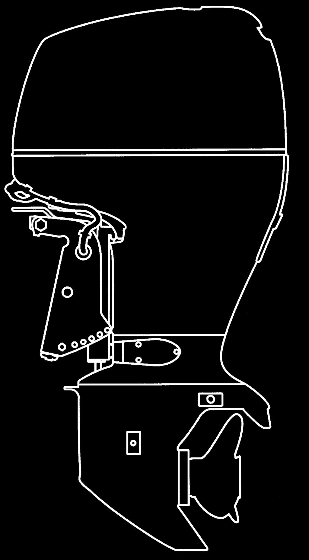
15 COMPONENT AND CONTROL LOCATIONS ENGINE COVER SPARK PLUG (under coil) CONTROLS AND FEATURES JUNCTION BOX (FUSES) OIL FILLER CAP NMEA INTERFACE COUPLER ENGINE COVER LATCH OIL LEVEL DIPSTICK POWER TILT SWITCH STERN BRACKET MANUAL RELIEF VALVE ANODE FLUSH PORT CONNECTOR COOLING SYSTEM INDICATOR ENGINE OIL DRAIN BOLT (inside cover) TILT LOCK LEVER PRODUCT IDENTIFICATION NUMBER ANODE PROPELLER (optional equipment) ANODE ANTIVENTILATION PLATE EXHAUST PORT/WATER OUTLET PORT TRIM TAB GEAR OIL LEVEL CHECK SCREW COOLING WATER INTAKE PORT GEAR OIL DRAIN/FILL SCREW 13
16 CONTROLS AND FEATURES Remote Controls (optional equipment) 14 Side-Mount Control Type GEARSHIFT/THROTTLE CONTROL LEVER POWER TRIM/TILT SWITCH SPARE EMERGENCY STOP SWITCH CLIP BUZZER (inside) CONTROL LEVER FRICTION ADJUSTER EMERGENCY STOP SWITCH LANYARD NEUTRAL RELEASE LEVER INDICATORS (Oil pressure, Overheat, Alternator, Malfunction) FAST IDLE LEVER IGNITION SWITCH IGNITION SWITCH KEY EMERGENCY STOP SWITCH EMERGENCY STOP SWITCH CLIP Panel-Mount Control Type GEARSHIFT/THROTTLE CONTROL LEVER POWER TRIM/TILT SWITCH FAST IDLE BUTTON Control Panel (for Panel-Mount Type) BUZZER IGNITION SWITCH EMERGENCY STOP SWITCH CLIP EMERGENCY STOP SWITCH LANYARD NEUTRAL RELEASE LEVER INDICATORS (Oil pressure, Overheat, Alternator, Malfunction) EMERGENCY STOP SWITCH
17 CONTROLS AND FEATURES Top-Mount Type (Single Outboard Motor Type) GEARSHIFT/THROTTLE CONTROL LEVER (Dual Outboard Motor Type) GEARSHIFT/THROTTLE CONTROL LEVERS POWER TRIM/TILT SWITCH (LEFT) POWER TRIM/TILT SWITCH POWER TRIM/TILT SWITCH (RIGHT) FAST IDLE BUTTON Control Panel (Top-Mount Single Type) FAST IDLE BUTTON (for Top-Mount Dual Type) BUZZER IGNITION SWITCH EMERGENCY STOP SWITCH CLIP INDICATORS (Oil pressure, Overheat, Alternator, Malfunction) EMERGENCY STOP SWITCH EMERGENCY STOP SWITCH LANYARD 15
18 CONTROLS AND FEATURES Instruments (optional equipment) Tachometer Digital Speedometer Trolling Control Switch Panel Trim Meter Digital Tachometer TRL (Trolling) CONTROL SWITCH 16
19 CONTROLS AND FEATURES CONTROLS Side-Mount Type Ignition Switch OFF ON START Turning the ignition switch key to the START position operates the starter motor. The key automatically returns to the ON position when released from the START position. The engine will not start unless the gearshift/throttle control lever is in the N (neutral) position (p. 41 ) and the emergency stop switch clip is in the emergency stop switch. Emergency Stop Switch Clip and Emergency Stop Switch EMERGENCY STOP SWITCH IGNITION SWITCH Turning the ignition switch to the OFF position stops the engine. EMERGENCY STOP SWITCH CLIP EMERGENCY STOP SWITCH LANYARD The ignition switch controls the ignition system and the starter motor. EMERGENCY STOP SWITCH CLIP EMERGENCY STOP SWITCH LANYARD 17
20 CONTROLS AND FEATURES The emergency stop switch clip must be inserted in the emergency stop switch in order for the engine to start and run. The emergency stop switch lanyard must be attached securely to the operator or to the operator s PFD (Personal Flotation Device). When used as described, the emergency stop switch clip and emergency stop switch lanyard system stops the engine if the operator falls away from the controls. A spare switch clip is stored in a slot in the control housing (optional equipment). SPARE SWITCH CLIP Gearshift/Throttle Control Lever GEARSHIFT/THROTTLE CONTROL LEVER NEUTRAL RELEASE LEVER The gearshift/throttle control lever controls engine speed and selects F (forward), N (neutral), or R (reverse) gears. 18
21 CONTROLS AND FEATURES F (FORWARD) N (NEUTRAL) SHIFT SHIFT R (REVERSE) Fast Idle Lever FAST IDLE LEVER THROTTLE OPENING MINIMUM MINIMUM THROTTLE OPENING MAXIMUM MAXIMUM GEARSHIFT/THROTTLE CONTROL LEVER Moving the control lever 30 from N (neutral) selects the gear, and further movement increases engine speed. The control lever automatically locks itself in the N (neutral) position. To move the lever out of the N (neutral) position, you must squeeze the neutral release lever on the underside of the lever handle. A friction adjuster near the base of the control lever adjusts the operating resistance of the control lever. Refer to p. 52. Less friction allows easier control lever movement. More friction helps to hold a steady throttle setting while cruising. Use the fast idle lever to accelerate engine warm-up after starting the engine. Do not use the fast idle lever when starting the engine. See page 43 for engine warm-up instructions. 19
22 CONTROLS AND FEATURES N (neutral) FAST IDLE LEVER MAXIMUM FAST IDLE LOWEST POSITION The fast idle lever allows you to increase the idle speed only when the control lever is in the N (neutral) position. Place the fast idle lever in its lowest position to cancel the fast idle and return the control lever to normal operation. Panel-Mount Type Ignition Switch OFF IGNITION SWITCH ON START The ignition switch controls the ignition system and the starter motor. Turning the ignition switch key to the START position operates the starter motor. The key automatically returns to the ON position when released from the START position. The engine will not start unless the gearshift/throttle control lever is in the N (neutral) position (p. 44 ) and the emergency stop switch clip is in the emergency stop switch. Turning the ignition switch to the OFF position stops the engine. 20
23 CONTROLS AND FEATURES Emergency Stop Switch Clip and Emergency Stop Switch EMERGENCY STOP SWITCH EMERGENCY STOP SWITCH LANYARD EMERGENCY STOP SWITCH CLIP The emergency stop switch clip must be inserted in the emergency stop switch in order for the engine to start and run. The emergency stop switch lanyard must be attached securely to the operator or to the operator s PFD (Personal Flotation Device). When used as described, the emergency stop switch clip and emergency stop switch lanyard system stops the engine if the operator falls away from the controls. A spare switch clip (optional equipment) can be stored in the tool bag. SPARE SWITCH CLIP (optional equipment) EMERGENCY STOP SWITCH CLIP EMERGENCY STOP SWITCH LANYARD 21
24 CONTROLS AND FEATURES Gearshift/Throttle Control Lever GEARSHIFT/THROTTLE CONTROL LEVER NEUTRAL RELEASE LEVER The gearshift/throttle control lever controls engine speed and selects F (forward), N (neutral), or R (reverse) F (FORWARD) THROTTLE OPENING MAXIMUM N (NEUTRAL) SHIFT MINIMUM Moving the control lever 35 from N (neutral) selects the gear, and further movement increases engine speed. SHIFT MINIMUM gears. to p. 52. The control lever automatically locks itself in the N (neutral) position. To move the lever out of the N (neutral) position, you must squeeze the neutral release lever on the underside of the lever handle. R (REVERSE) THROTTLE OPENING MAXIMUM GEARSHIFT/THROTTLE CONTROL LEVER A friction adjuster near the base of the control lever adjusts the operating resistance of the control lever. Refer Less friction allows easier control lever movement. More friction helps to hold a steady throttle setting while cruising. 22
25 CONTROLS AND FEATURES Fast Idle Button F(forward) N (neutral) R (reverse) It is necessary to position the control lever in the N (neutral) position to push in the fast idle button. CONTROL LEVER Pull up NEUTRAL RELEASE LEVER Return the control lever to N (neutral) position to cancel the fast idle operation. Push FAST IDLE BUTTON Use the fast idle button to accelerate engine warm-up after starting the engine. Do not use the fast idle button when starting the engine. See page 45 for engine warm-up instructions. FAST IDLE BUTTON The fast idle button allows you to increase the idle speed without engaging the drive gears. Move the control lever forward or reverse after pushing in the fast idle button to increase the idle speed. 23
26 CONTROLS AND FEATURES Top-Mount Type Ignition Switch OFF ON IGNITION SWITCH START The ignition switch controls the ignition system and the starter motor. Turning the ignition switch key to the START position operates the starter motor. The key automatically returns to the ON position when released from the START position. The engine will not start unless the gearshift/throttle control lever is in the N (neutral) position (p. 47 ) and the emergency stop switch clip is in the emergency stop switch. Turning the ignition switch to the OFF position stops the engine. Emergency Stop Switch Clip and Emergency Stop Switch EMERGENCY STOP SWITCH EMERGENCY STOP SWITCH LANYARD EMERGENCY STOP SWITCH CLIP 24 EMERGENCY STOP SWITCH LANYARD EMERGENCY STOP SWITCH CLIP
27 The emergency stop switch clip must be inserted in the emergency stop switch in order for the engine to start and run. The emergency stop switch lanyard must be attached securely to the operator or to the operator s PFD (Personal Flotation Device). When used as described, the emergency stop switch clip and emergency stop switch lanyard system stops the engine if the operator falls away from the controls. A spare switch clip (optional equipment) can be stored in the tool bag. Gearshift/Throttle Control Lever SINGLE TYPE DUAL TYPE GEARSHIFT/THROTTLE CONTROL LEVER CONTROLS AND FEATURES The gearshift/throttle control lever(s) controls engine speed and selects F (forward), N (neutral), or R (reverse) gears. SPARE SWITCH CLIP (optional equipment) GEARSHIFT/THROTTLE CONTROL LEVERS 25
28 CONTROLS AND FEATURES Moving the control lever 35 from N (neutral) selects the gear, and further movement increases engine speed. A friction adjuster inside the control box adjusts the operating resistance of the control lever(s). Refer to p. 52. Less friction allows easier control lever movement. More friction helps to hold a steady throttle setting while cruising. N (NEUTRAL) F (FORWARD) R (REVERSE) SHIFT SHIFT MINIMUM THROTTLE OPENING MINIMUM THROTTLE OPENING MAXIMUM MAXIMUM GEARSHIFT/THROTTLE CONTROL LEVER 26
29 CONTROLS AND FEATURES Fast Idle Button F(forward) N (neutral) R (reverse) It is necessary to position the control lever in the N (neutral) position to push in the fast idle button. Return the control lever to N (neutral) position to cancel the fast idle operation. CONTROL LEVER FAST IDLE BUTTON Use the fast idle button to accelerate engine warm-up after starting the engine. Do not use the fast idle button when starting the engine. See page 48 for engine warm-up instructions. Push FAST IDLE BUTTON The fast idle button allows you to increase the idle speed without engaging the drive gears. Move the control lever forward or reverse after pushing in the fast idle button to increase the idle speed. 27
30 CONTROLS AND FEATURES Common Controls Power Trim/Tilt Switch (Side-Mount Type) POWER TRIM/TILT SWITCH (Panel-Mount Type) 28 CONTROL LEVER POWER TRIM/TILT SWITCH CONTROL LEVER (Top-Mount Type) SINGLE TYPE POWER TRIM/TILT SWITCH CONTROL LEVER DUAL TYPE POWER TRIM/TILT SWITCH (LEFT) (RIGHT) CONTROL LEVERS The power trim/tilt switch is located on the control lever. It is a rocker switch with UP and DN (down) positions for changing the angle of the outboard motor. You can use the power trim/tilt switch anytime whether the boat is underway, stopped, or the ignition switch is in the OFF position. It is necessary for the ignition switch to be in the ON position for the trim meter to indicate the outboard motor angle. Trim the outboard motor to obtain the best performance and stability (p. 53 ). Tilt the outboard motor for shallow water operation, beaching, launching, or mooring. For dual mount outboard motors, tilt them up at the same time.
31 CONTROLS AND FEATURES Power Tilt Switch Manual Relief Valve Tilt Lock Lever MANUAL RELIEF VALVE FREE LOCK POWER (To fix) MANUAL (To release) POWER TILT SWITCH The power tilt switch is located on the engine pan. It is a rocker switch with UP and DN (down) positions for changing the angle of the outboard motor. The power tilt switch will operate without turning the ignition switch ON. This switch is used with the engine stopped to raise the outboard motor for mooring, trailering, or maintenance. The outboard motor can be tilted manually after opening the manual relief valve. This allows the outboard motor to be tilted up or down when no battery is connected. Check that nobody is under the outboard motor before opening the manual relief valve. If the manual relief valve is loosened (turned counterclockwise) when the outboard motor is tilted up, the outboard motor will suddenly tilt down. TILT LOCK LEVER The tilt lock lever is used to support the outboard motor in the fully-raised position. When the boat is to be moored for a long time, tilt the outboard motor up as far as it will go. Then move the tilt lock lever to the LOCK position, and gently lower the outboard motor until the lever contacts the stern bracket. 29
32 CONTROLS AND FEATURES TRL (Trolling) Control Switch (optional equipment) SWITCH PANEL Engine Cover Latch Trim Tab TRIM TAB BOLT UNLOCK TRL (Trolling) CONTROL SWITCH ENGINE COVER LATCH TRIM TAB The Trolling Control Switch is a rocker switch with UP and DN (down) positions to adjust the trolling speed up or down in 50 RPM increments within the range of 650 to 900 RPM. If you press and hold the TRL control switch while cruising with the throttle closed, the mode changes to trolling mode (p. 55 ). 30 The engine cover latch fastens the engine cover to the outboard motor. The trim tab compensates for torque steer, which is a reaction of the outboard motor to propeller rotation. If uncompensated, torque steer would make the outboard motor tend to turn to one side. When the trim tab is correctly adjusted (p. 64 ), steering effort is equal in both directions.
33 INSTRUMENTS Trim Meter (optional equipment) Tachometer (optional equipment) CONTROLS AND FEATURES Digital Tachometer (optional equipment) The trim meter indicates the relative trim angle of the outboard motor. Refer to the trim meter when using the power trim/tilt switch to achieve the best performance from the boat. The tachometer shows engine speed in revolutions per minute. Refer to the tachometer when using the throttle and power trim/tilt controls to achieve the best performance from the boat. Digital Tachometer includes the following functions. Tachometer Hour Meter Trim Meter Oil Pressure Indicator Overheat Indicator ACG Indicator Malfunction Indicator Refer to the Operation Guide included with the Digital Tachometer for operation information. 31
34 CONTROLS AND FEATURES Digital Speedometer (optional equipment) NMEA Interface Coupler NMEA2000 based information on engine speed, fuel consumption, and various warnings can be read by connecting to the motor with the interface cable (optional equipment). Contact your dealer for more information. Digital Speedometer includes the following functions. Speedometer Fuel Level Meter Voltmeter Tripmeter Fuel Integration Meter Fuel Economy Meter Fuel Flow Meter Water Separator Indicator Refer to the Operation Guide included with the Digital Speedometer for operation information. 32 NMEA INTERFACE COUPLER (6 pin black)
35 CONTROLS AND FEATURES INDICATORS The indicator lights come on and the buzzer sounds when you turn the ignition switch ON, allowing you to see that they are working. If an indicator does not light during this test, it cannot alert you if that system develops a problem. Have your Honda Marine dealer check for burned-out bulbs or other problems. Under normal conditions, the following occur when the ignition switch is turned ON: The ACG, Malfunction, Oil Pressure, and Overheat indicators light. The buzzer will beep twice. The Malfunction, Oil Pressure, and Overheat indicators will go out after the second beep. The ACG indicator will go out after the engine starts. The Oil Pressure indicator will light again after the engine starts and will stay lit to indicate the oil pressure is normal. Alternator (ACG) Indicator (Side-Mount Type) BUZZER ACG INDICATOR BUZZER (RED) ACG INDICATOR (RED) (Panel-Mount/Top-Mount Types) The ACG indicator turns on and the buzzer sounds in one-second intervals when the charging system is faulty. Malfunction Indicator (Side-Mount Type) BUZZER MALFUNCTION INDICATOR (RED) MALFUNCTION INDICATOR (RED) (Panel-Mount/Top-Mount Types) BUZZER When the engine control system detects an engine control system malfunction, the malfunction indicator turns on and the buzzer sounds at one-second intervals. 33
36 CONTROLS AND FEATURES Oil Pressure Indicator (Side-Mount Type) BUZZER OIL PRESSURE INDICATOR OIL PRESSURE INDICATOR (GREEN) (Panel-Mount/Top-Mount Types) (GREEN) When the oil pressure indicator is lit, oil pressure is OK. If oil pressure becomes low, the indicator will go off, and the engine protection system will limit engine speed. Refer to TAKING CARE OF UNEXPECTED PROBLEMS, on p. 98. All models are equipped with a buzzer that sounds continuously when the oil pressure indicator goes off. Low oil pressure indicates that the engine oil level is low or that there is a problem with the engine lubrication system. Overheat Indicator (Side-Mount Type) BUZZER OVERHEAT INDICATOR (RED) (Panel-Mount/Top-Mount Types) OVERHEAT INDICATOR (RED) BUZZER BUZZER 34
37 When the alert triggers, the overheat indicator comes on and the buzzer sounds a steady tone as the engine speed is reduced to 1,800 rpm. If the condition persists for another 20 seconds, the engine shuts off. Refer to TAKING CARE OF UNEXPECTED PROBLEMS,on p. 99. Cooling System Indicator COOLING SYSTEM INDICATOR CONTROLS AND FEATURES OTHER FEATURES Water Separator Buzzer The water separator buzzer sounds a rapid, repeating signal when water has accumulated in the water separator. All models are equipped with a buzzer that sounds continuously when the red light comes on. Engine overheating may be the result of clogged water intakes. Water should flow from the cooling system indicator while the engine is running. This shows that water is circulating through the cooling system. If water stops flowing while the engine is running, it indicates a cooling system problem, such as clogged water intakes, which will cause engine overheating. WATER SEPARATOR The cooling system indicator discharge port can also become plugged. 35
38 CONTROLS AND FEATURES Rev Limiter Anodes Fuel Priming Bulb The engine is equipped with a rev limiter to prevent the possibility of mechanical damage from excessive engine speed. The rev limiter may be activated during operation, limiting engine speed, if the outboard motor is trimmed or tilted up excessively, or when propeller ventilation occurs during a sharp turn. ANODE (each side) ANODE (stern bracket) UP OUTLET END (outboard motor side) PRIMING BULB INLET END (tank side) If the rev limiter is activated, check the trim angle of the outboard motor. Check to see if the correct propeller is installed. The anodes are made of a sacrificial material that helps to protect the outboard motor from corrosion. There are two anodes on the gear case, one on the stern bracket and two small anodes in the water passages of the engine block. A priming bulb is built into the fuel hose that connects the fuel tank to the outboard motor. Before starting the engine, hold the priming bulb up in the direction of the arrow; then squeeze the priming bulb until it feels firm. This will ensure that fuel is supplied to the engine (p. 40 ). 36
39 ARE YOU READY TO GET UNDERWAY? Your safety is your responsibility. A little time spent in preparation will significantly reduce your risk of injury. Knowledge Read and understand this manual. Know what the controls do and how to operate them. Familiarize yourself with the outboard motor and its operation before you get underway. Know what to do in case of an emergency. Familiarize yourself with all laws and regulations relating to boating and the use of outboard motors. Safety Always wear a PFD (Personal Flotation Device) while on the boat. Attach the emergency stop switch lanyard securely to the operator or to the operator s PFD. IS YOUR OUTBOARD MOTOR READY TO GO? For your safety, and to maximize the service life of your equipment, it is very important to take a few moments before you operate the outboard motor to check its condition. Be sure to take care of any problem you find, or have your authorized Honda Marine dealer correct it, before you operate the outboard motor. BEFORE OPERATION Improperly maintaining this outboard motor or failing to correct a problem before operation can cause a malfunction in which you could be seriously hurt or killed. Always perform a preoperation inspection before each operation, and correct any problem. Before beginning your pre-operation checks, be sure the ignition switch is in the OFF position. 37
40 BEFORE OPERATION Safety Inspection 38 Look around the outboard motor for signs of oil or gasoline leaks. Check that the fuel hose is undamaged and properly connected. Wipe up any spills before starting the engine. Check the stern bracket to be sure the outboard motor is securely installed. Check that all controls are operating properly. Replace any damaged parts. Check that all fasteners are in place and securely tightened. Check the emergency stop switch for proper operation. Start the engine (p. 41, 44 or 46 ). Make sure the engine stops by pulling the emergency stop switch clip from the emergency stop switch. Maintenance Inspection Check the engine oil level (p. 66 ). Running the engine with a low oil level can cause engine damage. Check to be sure the propeller is undamaged and the castle nut is secured with the cotter pin (p. 83 ). Check that the anodes are securely attached to the stern bracket and the gear case (p. 82 ) and are not excessively worn. The anodes help protect the outboard motor from corrosion. Make sure the tool kit is onboard (p. 61 ). Replace any missing items. Check the fuel level in the fuel tank (p. 75 ). Check that the battery fluid is between the upper and lower levels, and the battery leads are connected securely. Check the water separator for water contamination (p. 80 ).
41 SAFE OPERATING PRECAUTIONS To safely realize the full potential of this outboard motor, you need a complete understanding of its operation and a certain amount of practice with its controls. Before operating the outboard motor for the first time, please review the IMPORTANT SAFETY INFORMATION on page 7 and the chapter titled BEFORE OPERATION. For your safety, do not start or run the engine in a confined or partly enclosed area. Your engine s exhaust contains poisonous carbon monoxide, a colorless, odorless gas that can collect rapidly. Breathing carbon monoxide can cause loss of consciousness and may lead to death. BREAK-IN PROCEDURE Break-in period: 10 hours Proper break-in operation allows the moving parts to wear in smoothly for best performance and long service life. Avoid continuous operation at a steady speed. First 15 minutes: Run the engine at trolling speed. Use the minimum throttle opening necessary to operate the boat at a safe trolling speed. Next 45 minutes: Run the engine up to a maximum of 2,000 to 3,000 rpm, which is about 10% to 30% of maximum throttle opening. Operating at maximum 2,000 3,000 rpm should be limited to 50% of the 45 minutes. OPERATION Next 60 minutes: Run the engine up to a maximum of 4,000 to 5,000 rpm, which is about 50% to 80% of maximum throttle opening. Operating at maximum 4,000 5,000 rpm should be limited to 50% of the 60 minutes. 30-second full-throttle bursts are OK, but do not operate the engine continuously at full throttle. For boats that plane easily, bring the boat up on plane, and then reduce the throttle opening to the recommended rpm range. Next 8 hours: Do not run the engine at full throttle for more than 5 minutes at a time. 39
42 OPERATION FUEL PRIMING UP OUTLET END (outboard motor side) PRIMING BULB INLET END (tank side) Hold the priming bulb up in the direction of the arrow; then squeeze the priming bulb several times until it feels firm, indicating that fuel has reached the engine. Gasoline is highly flammable and explosive. You can be burned or seriously injured when handling fuel. Stop the engine and keep heat, sparks, and flame away. Handle fuel only outdoors. Wipe up spills immediately. Check to be sure there are no fuel leaks before starting the engine. Do not touch the priming bulb with the engine running or when tilting up the outboard motor. The vapor separator could overflow. 40
43 OPERATION STARTING THE ENGINE Control Side-Mount Type... p. 41 Panel-Mount Type... p. 44 Top-Mount Type... p. 46 Side-Mount Type EMERGENCY STOP SWITCH to the operator s PFD (Personal Flotation Device). The engine will not start or run, unless the emergency stop switch clip is in the emergency stop switch. The emergency stop switch clip and emergency stop switch lanyard system is a safety device that will stop the engine if you fall away from the controls while operating the boat. CONTROL LEVER N (neutral) EMERGENCY STOP SWITCH CLIP 1. EMERGENCY STOP SWITCH LANYARD Put the emergency stop switch clip in the emergency stop switch, and attach the emergency stop switch lanyard securely to the operator or Always attach the emergency stop switch lanyard securely to the operator or to the operator s PFD before starting the engine. Before leaving the dock, check the operation of the emergency stop switch. 2. Set the control lever in the N (neutral) position. The engine will not start if the F (forward) or R (reverse) gears are engaged. 41
44 OPERATION OFF ON START If the engine fails to start within 5 seconds, release the key and wait at least 10 seconds before operating the starter again. LOWEST POSITION FAST IDLE LEVER 3. Leave the fast idle lever in the 4. OFF (fully lowered) position. The fast idle lever cannot be raised unless the control lever is in the N (neutral) position. The control lever cannot be moved away from the N (neutral) position unless the fast idle lever is lowered. IGNITION SWITCH KEY Turn the ignition switch key to the ON position; the buzzer will sound twice. 5. Turn the ignition switch key to the START position and hold it there until the engine starts. When the engine starts, release the key, allowing it to return to the ON position. Using the electric starter f or more than 5 seconds at a time will overheat the starter motor and can damage it. Turning the ignition switch key to the START position while the engine is running can damage the starter motor and f lywheel. 42
45 6. MAXIMUM FAST IDLE FAST IDLE RANGE FAST IDLE LEVER Before getting underway, allow the engine to warm-up sufficiently to ensure good performance. Above 41 F (5 C), warm-up the engine for at least 3 minutes. Below 41 F (5 C), warm-up the engine for at least 5 minutes at 2,000 rpm. Raise the fast idle lever to achieve approximately 2,000 rpm. If the engine is not properly warmed up bef ore raising the engine speed, the buzzer and overheat indicator may activate and the engine speed will be automatically reduced. The cooling system may f reeze in areas where the temperature reaches 32 F (0 C) or below. Cruising at high speed without warming the engine up may cause engine damage. 7. OPERATION During the warm-up period, check the oil pressure indicator (p. 34 ), overheat indicator (p. 34 ), and cooling system indicator (p. 35 ). If the indicators show any abnormal condition, immediately stop the engine and determine the cause of the problem. Refer to TAKING CARE OF UNEXPECTED PROBLEMS on p If the fast idle lever was used to warm-up the engine, gradually lower the lever as the engine warms up. When the fast idle lever is fully lowered, the control lever can be moved away from the N (neutral) position. 43
46 OPERATION Panel-Mount Type EMERGENCY STOP SWITCH The engine will not start or run, unless the emergency stop switch clip is in the emergency stop switch. N (neutral) EMERGENCY STOP SWITCH LANYARD The emergency stop switch clip and emergency stop switch lanyard system is a safety device that will stop the engine if you fall away from the controls while operating the boat. EMERGENCY STOP SWITCH CLIP Always attach the emergency stop switch lanyard securely to the 1. Put the emergency stop switch clip operator or to the operator s PFD 2. in the emergency stop switch, and before starting the engine. attach the emergency stop switch lanyard securely to the operator or Before leaving the dock, check the to the operator s PFD (Personal operation of the emergency stop Flotation Device). switch. CONTROL LEVER Set the control lever in the N (neutral) position. The engine will not start if the F (forward) or R (reverse) gears are engaged. 44
47 OPERATION ON START If the engine fails to start within 5 seconds, release the key and wait at least 10 seconds before operating the starter again. N (neutral) OFF IGNITION SWITCH KEY 3. Turn the ignition switch key to the ON position; the buzzer will sound twice. 4. Turn the ignition switch key to the START position and hold it there until the engine starts. When the engine starts, release the key, allowing it to return to the ON position. Using the electric starter f or more than 5 seconds at a time will overheat the starter motor and can damage it. Turning the ignition switch key to the START position while the engine is running can damage the starter motor and f lywheel. CONTROL LEVER FAST IDLE BUTTON 5. Before getting underway, allow the engine to warm-up sufficiently to ensure good performance. Above 41 F (5 C), warm-up the engine for at least 3 minutes. Below 41 F (5 C), warm-up the engine for at least 5 minutes at 2,000 rpm. Push the fast idle button, and then move the control lever forward or reverse to open the throttle and achieve approximately 2,000 rpm. 45
48 OPERATION If the engine is not properly warmed up bef ore raising the engine speed, the buzzer and overheat indicator may activate and the engine speed will be automatically reduced. The cooling system may f reeze in areas where the temperature reaches 32 F (0 C) or below. Cruising at high speed without warming the engine up may cause engine damage. 6. During the warm-up period, check the oil pressure indicator (p. 34 ), overheat indicator (p. 34 ), and cooling system indicator (p. 35 ). If the indicators show any abnormal condition, immediately stop the engine and determine the cause of the problem. Refer to TAKING CARE OF UNEXPECTED PROBLEMS on p If the fast idle control was used to warm-up the engine, gradually return the control lever to the N (neutral) position as the engine warms up. Top-Mount Type EMERGENCY STOP SWITCH EMERGENCY STOP SWITCH CLIP 1. EMERGENCY STOP SWITCH LANYARD Put the emergency stop switch clip in the emergency stop switch, and attach the emergency stop switch lanyard securely to the operator or to the operator s PFD (Personal Flotation Device). 46
49 OPERATION The engine will not start or run, unless the emergency stop switch clip is in the emergency stop switch. N (neutral) ON START The emergency stop switch clip and emergency stop switch lanyard system is a safety device that will stop the engine if you fall away from the controls while operating the boat. Always attach the emergency stop switch lanyard securely to the operator or to the operator s PFD before starting the engine. Before leaving the dock, check the operation of the emergency stop switch. CONTROL LEVER 2. Set the control lever in the N 3. (neutral) position. The engine will not start if the F (forward) or R (reverse) gears are engaged. OFF IGNITION SWITCH KEY Turn the ignition switch key to the ON position; the buzzer will sound twice. 4. Turn the ignition switch key to the START position and hold it there until the engine starts. When the engine starts, release the key, allowing it to return to the ON position. 47
50 OPERATION 48 If the engine fails to start within 5 seconds, release the key and wait at least 10 seconds before operating the starter again. Using the electric starter f or more than 5 seconds at a time will overheat the starter motor and can damage it. Turning the ignition switch key to the START position while the engine is running can damage the starter motor and f lywheel. CONTROL LEVER N (neutral) FAST IDLE BUTTON 5. Before getting underway, allow the engine to warm-up sufficiently to ensure good performance. Above 41 F (5 C), warm-up the engine for at least 3 minutes. Below 41 F (5 C), warm-up the engine for at least 5 minutes at 2,000 rpm. Push the fast idle button, and then move the control lever forward or reverse to open the throttle and achieve approximately 2,000 rpm. If the engine is not properly warmed up bef ore raising the engine speed, the buzzer and overheat indicator may activate and the engine speed will be automatically reduced. The cooling system may f reeze in areas where the temperature reaches 32 F (0 C) or below. Cruising at high speed without warming the engine up may cause engine damage.
51 6. During the warm-up period, check the oil pressure indicator (p. 34 ), overheat indicator (p. 34 ), and cooling system indicator (p. 35 ). If the indicators show any abnormal condition, immediately stop the engine and determine the cause of the problem. Refer to TAKING CARE OF UNEXPECTED PROBLEMS on p If the fast idle control was used to warm-up the engine, gradually return the control lever to the N (neutral) position as the engine warms up. STOPPING THE ENGINE Emergency Engine Stopping Side-Mount Type EMERGENCY STOP SWITCH EMERGENCY STOP SWITCH CLIP EMERGENCY STOP SWITCH EMERGENCY STOP SWITCH LANYARD PULL Panel-Mount/Top-Mount Types CONTROL PANEL EMERGENCY STOP SWITCH LANYARD PULL OPERATION To stop the engine in an emergency, pull the emergency stop switch clip out of the emergency stop switch by pulling the emergency stop switch lanyard. We suggest that you stop the engine this way occasionally to verify that the emergency stop switch is operating properly. Before leaving the dock, check the operation of the emergency stop switch. Turn the ignition switch key to the OFF position after verifying the emergency stop switch operation. EMERGENCY STOP SWITCH CLIP 49
52 OPERATION Normal Engine Stopping Side-Mount Type N (neutral) Top-Mount Type N (neutral) Panel-Mount/Top-Mount Types OFF CONTROL LEVER CONTROL LEVER IGNITION SWITCH KEY Panel-Mount Type CONTROL LEVER N (neutral) 1. Move the control lever(s) to the N 2. (neutral) position. After cruising at full throttle, cool down the engine by idling for a few minutes before stopping the engine. Side-Mount Type OFF Turn the ignition switch key to the OFF position to stop the engine. In the event that the engine does not stop when the ignition switch key is turned to OFF, press the emergency stop switch until the engine stops. 3. When the boat is not in use, remove and store the ignition switch key and the emergency stop switch clip and lanyard. IGNITION SWITCH KEY 50
53 OPERATION GEARSHIFT AND THROTTLE OPERATION Side-Mount Type CONTROL LEVER NEUTRAL RELEASE LEVER Panel-Mount Type F(forward) CONTROL LEVER Top-Mount Type N (neutral) R (reverse) NEUTRAL RELEASE LEVER To shift gears, move the control lever to select the F (forward), N (neutral), or R (reverse) gear. The control lever cannot be moved from the N (neutral) position unless the neutral release lever is squeezed (side-mount/panel-mount types). Moving the control lever beyond the gear selection range increases engine speed. N (neutral) F(forward) N (neutral) R (reverse) F(forward) R (reverse) CONTROL LEVER 51
54 OPERATION Side-Mount Type TO INCREASE FRICTION Top-Mount Type STEERING Steer the boat in the same manner as an automobile. TO DECREASE FRICTION CONTROL LEVER FRICTION ADJUSTER Panel-Mount Type CONTROL LEVER FRICTION ADJUSTER TO INCREASE FRICTION TO INCREASE FRICTION TO DECREASE FRICTION CONTROL LEVER FRICTION ADJUSTER Adjust the control lever friction adjuster so the control lever will hold a constant throttle setting while cruising. TO DECREASE FRICTION 52
55 CRUISING Engine Speed For best fuel economy, limit the throttle opening to 80%. Use the throttle friction control (p. 52 ) to help you hold a steady speed. For rough water conditions or large waves, slow down to prevent the propeller from rising out of the water. The engine is equipped with a rev limiter to prevent the possibility of mechanical damage from excessive engine speed. If, for example, the outboard motor is tilted excessively or propeller ventilation occurs during a sharp turn, the engine may overrev, activating the rev limiter. If engine speed becomes unstable at high speed due to activation of the rev limiter, reduce speed and check the trim angle of the outboard motor. Trim Use the power trim/tilt switch to trim the outboard motor for the best performance and stability. You can use the power trim/tilt switch at any time, whether the boat is underway or stopped. Press the UP or DN (down) side of the switch to adjust the angle of the outboard motor. Refer to the trim meter (p. 31) for an indication of whether the outboard motor is trimmed high or low. It is necessary to trim the angle of the outboard motor to compensate for changes in boat load, weight distribution, water conditions, or propeller selection. OPERATION Under normal conditions, the boat will perform best when the antiventilation plate is level with the water surface. When cruising into a high wind, trim the outboard motor down slightly to level the boat and improve stability. With a tail wind, trim the outboard motor up slightly. Excessive trim/tilt angle during operation can cause propeller ventilation, overheating, and water pump damage. 53
56 OPERATION Side-Mount Type POWER TRIM/TILT SWITCH Top-Mount Type (single type) POWER TRIM/TILT SWITCH OUTBOARD MOTOR TRIMMED TOO LOW OUTBOARD MOTOR TRIMMED TOO HIGH OUTBOARD MOTOR TRIMMED CORRECTLY Panel-Mount Type POWER TRIM/TILT SWITCH (dual type) POWER TRIM/TILT SWITCH (LEFT) (RIGHT) BOW TOO LOW DUE TO 1. LOAD IN THE FRONT 2. OUTBOARD MOTOR TRIMMED TOO LOW BOW TOO HIGH DUE TO 1. LOAD IN THE REAR 2. OUTBOARD MOTOR TRIMMED TOO HIGH 54
57 Trolling Speed Control (optional equipment) SWITCH PANEL TRL (Trolling) CONTROL SWITCH DN: Reduce engine speed UP: Increase engine speed The engine must be fully warmed up before you can activate the Trolling Speed Control. Place the outboard motor in-gear with the throttle control in the fully closed (idle) position. Press and hold the UP or DN side of the TRL control switch to activate the Trolling Speed Control. The buzzer will make one long sound indicating activation. The initial trolling speed is set at 650 RPM. The engine speed can be adjusted in 50 RPM increments by pressing the UP or DN side of the TRL control switch. A short sound of the buzzer occurs each time the engine speed is adjusted. In Trolling Speed Control mode, the engine speed can be adjusted between 650 and 900 RPM. Continuing to press the switch when at either of these limits will result in two short sounds from the buzzer. The throttle control will operate OPERATION when in the Trolling Speed Control mode, but once the speed reaches 3,000 RPM, the Trolling Speed Control is deactivated. If 3,000 RPM is not reached and the throttle is closed, the engine speed will decrease to the Trolling Speed Control setting. 55
58 OPERATION TRIM TAB If steering effort is not equal in both directions, adjust the trim tab to compensate for torque steer, which is the reaction of the outboard motor to propeller rotation. 56 TRIM TAB TRIM TAB BOLT Adjust the trim tab with the engine stopped. Loosen the bolt above the trim tab, turn the trim tab, and then tighten the bolt securely. When the trim tab is correctly adjusted, steering effort will be equal in both directions. Refer to TRIM TAB ADJUSTMENT on p. 64. SHALLOW WATER OPERATION When operating in shallow water, use the power trim/tilt switch (p. 54 ) to tilt the outboard motor so that the propeller and gear case won t hit the bottom. Proceed at low speed, and monitor water flow from the cooling system indicator (p. 35 ) to be sure the outboard motor is not tilted so high that the water intakes are out of the water. An excessive trim/tilt angle during operation can cause propeller ventilation, overheating, and water pump damage. This type of damage is not covered by the Distributor s Limited Warranty (p. 114 ). 68 TILT ANGLE (VERTICAL LINE) TRIM ANGLE (when transom angle is 12 )
The engine exhaust from this product contains chemicals known to the State of California to cause cancer, birth defects, or other reproductive harm.
 The engine exhaust from this product contains chemicals known to the State of California to cause cancer, birth defects, or other reproductive harm. Keep this Owner s Manual handy, so you can refer to
OWNER S MANUAL BFT 200A 225A
 OWNER S MANUAL BFT 200A 225A The engine exhaust from this product contains chemicals known to the State of California to cause cancer, birth defects, or other reproductive harm. Keep this Owner s Manual
The engine exhaust from this product contains chemicals known to the State of California to cause cancer, birth defects, or other reproductive harm.
 The engine exhaust from this product contains chemicals known to the State of California to cause cancer, birth defects, or other reproductive harm. Keep this owner s manual handy, so you can refer to
Includes US and Canadian Models Honda Motor Co., Ltd. All Rights Reserved
 Includes US and Canadian Models 2017 Honda Motor Co., Ltd. All Rights Reserved The engine exhaust from this product contains chemicals known to the State of California to cause cancer, birth defects, or
The engine exhaust from this product contains chemicals known to the State of California to cause cancer, birth defects, or other reproductive harm.
 The engine exhaust from this product contains chemicals known to the State of California to cause cancer, birth defects, or other reproductive harm. Keep this Owner s Manual handy, so you can refer to
OWNER S MANUAL BFT 75A 90A
 OWNER S MANUAL BFT 75A 90A The engine exhaust from this product contains chemicals known to the State of California to cause cancer, birth defects, or other reproductive harm. Keep this Owner s Manual
BF200A/BF225A Owner s Manual
 BF200A/BF225A Owner s Manual 2003 Honda Motor Co., Ltd. -All Rights Reserved 2004 The engine exhaust from this product contains chemicals known to the State of California to cause cancer, birth defects,
The engine exhaust from this product contains chemicals known to the State of California to cause cancer, birth defects, or other reproductive harm.
 The engine exhaust from this product contains chemicals known to the State of California to cause cancer, birth defects, or other reproductive harm. Keep this owner s manual handy, so you can refer to
OWNER S MANUAL BFT 60A BFW 60A
 OWNER S MANUAL BFT 60A BFW 60A The engine exhaust from this product contains chemicals known to the State of California to cause cancer, birth defects, or other reproductive harm. Keep this Owner s Manual
Includes US and Canadian Models
 Includes US and Canadian Models The engine exhaust from this product contains chemicals known to the State of California to cause cancer, birth defects, or other reproductive harm. Keep this Owner s Manual
BF60A BFP60A Owner s Manual
 BF60A BFP60A Owner s Manual The engine exhaust from this product contains chemicals known to the State of California to cause cancer, birth defects, or other reproductive harm. Keep this Owner s Manual
The engine exhaust from this product contains chemicals known to the State of California to cause cancer, birth defects, or other reproductive harm.
 The engine exhaust from this product contains chemicals known to the State of California to cause cancer, birth defects, or other reproductive harm. Keep this owner s manual handy, so you can refer to
Includes US and Canadian Models. BF25D BF30D Owner s Manual
 Includes US and Canadian Models BF25D BF30D Owner s Manual The engine exhaust from this product contains chemicals known to the State of California to cause cancer, birth defects, or other reproductive
The engine exhaust from this product contains chemicals known to the State of California to cause cancer, birth defects, or other reproductive harm.
 C 2003 Honda Motor Co., Ltd. -All Rights Reserved 2004 The engine exhaust from this product contains chemicals known to the State of California to cause cancer, birth defects, or other reproductive harm.
BF25D BF30D Owner s Manual
 BF25D BF30D Owner s Manual 2004 Honda Motor Co., Ltd. -All Rights Reserved 2005 The engine exhaust from this product contains chemicals known to the State of California to cause cancer, birth defects,
BF4A BF5D BF6A. Includes US and Canadian Models Honda Motor Co., Ltd. All Rights Reserved
 BF4A BF5D BF6A Includes US and Canadian Models 2017 Honda Motor Co., Ltd. All Rights Reserved The engine exhaust from this product contains chemicals known to the State of California to cause cancer, birth
The engine exhaust from this product contains chemicals known to the State of California to cause cancer, birth defects, or other reproductive harm.
 The engine exhaust from this product contains chemicals known to the State of California to cause cancer, birth defects, or other reproductive harm. Keep this owner s manual handy, so you can refer to
The engine exhaust from this product contains chemicals known to the State of California to cause cancer, birth defects, or other reproductive harm.
 The engine exhaust from this product contains chemicals known to the State of California to cause cancer, birth defects, or other reproductive harm. Keep this Owner s Manual handy, so you can refer to
OWNER S MANUAL BFT 250A
 OWNER S MANUAL BFT 250A OWNER S MANUAL BFT 250A Original instructions 2016 Honda Motor Co, Ltd PGM-FI is a trademark of Honda Motor Co, Ltd registered in Japan and other countries Thank you for purchasing
Includes US and Canadian Models BF2.3D
 Includes US and Canadian Models BF2.3D The engine exhaust from this product contains chemicals known to the State of California to cause cancer, birth defects, or other reproductive harm. California Proposition
Includes US and Canadian Models Honda Motor Co., Ltd. All Rights Reserved
 Includes US and Canadian Models 2017 Honda Motor Co., Ltd. All Rights Reserved The engine exhaust from this product contains chemicals known to the State of California to cause cancer, birth defects, or
HONDA. Инструкция по эксплуатации (eng.)
") HONDA Инструкция по эксплуатации (eng.) Лодочные моторы BF 30 DK2 SHGU, BF 30 DK2 SRTU По вопросам продаж и поддержки обращайтесь: Архангельск (8182)63-90-72 Астана +7(7172)727-132 Белгород (4722)40-23-64
HONDA Инструкция по эксплуатации (eng.) Лодочные моторы BF 30 DK2 SHGU, BF 30 DK2 SRTU По вопросам продаж и поддержки обращайтесь: Архангельск (8182)63-90-72 Астана +7(7172)727-132 Белгород (4722)40-23-64
BF2D Owner s Manual 2006
 BF2D Owner s Manual 2005 Honda Motor Co., Ltd. -All Rights Reserved 2006 The engine exhaust from this product contains chemicals known to the State of California to cause cancer, birth defects, or other
Owner's Manual Outboard Motor BF8A
 Owner's Manual Outboard Motor BF8A 2000 1999 American Honda Motor Co., Inc. All Rights Reserved The engine exhaust from this product contains chemicals known to the State of California to cause cancer,
Make/Type/Size/Model Honda Generator EB 3500X & EB5000X Operators Manual Open Well Ventilated Area to Start & Shut Down Machine
 HONDA GENERATORS ARE DESIGNED TO GIVE SAFE AND DEPENDABLE SERVICE IF OPERATED ACCORDING TO INSTRUCTIONS. YOU CAN HELP PREVENT ACCIDENTS BY BEING FAMILIAR WITH YOUR GENERATORS CONTROLS AND BY OBSERVING
1200W INVERTER GENERATOR
 1200W INVERTER GENERATOR MODEL NO: IG1200 PART NO: 8877070 OPERATION & MAINTENANCE INSTRUCTIONS LS0117 INTRODUCTION Thank you for purchasing this CLARKE 1200W Inverter Generator. Before attempting to use
TP300 INDUSTRIAL TRASH PUMP OPERATOR S MANUAL
 TP300 INDUSTRIAL TRASH PUMP OPERATOR S MANUAL IT IS EXTREMELY IMPORTANT TO READ AND UNDERSTAND THE ENTIRE CONTENTS OF THIS OPERATOR S MANUAL BEFORE ATTEMPTING TO OPERATE THE PRODUCT. THIS EQUIPMENT IS
Owner s Manual. GENERATOR EU7000is. o2013 Honda Motor Co., Ltd. -All Rights Reserved. See page 81 for instructions on assembling your generator.
 Owner s Manual GENERATOR EU7000is o2013 Honda Motor Co., Ltd. -All Rights Reserved See page 81 for instructions on assembling your generator. The engine exhaust from this product contains chemicals known
Remote Engine Starter System I User s Information Manual
 Remote Engine Starter System I User s Information Manual A Few Words About Safety Your safety, and the safety of others, is very important. Operating this Remote Engine Starter System safely is an important
Owner s Manual. GENERATOR EU2000i. o Honda Motor Co., Ltd. -All Rights Reserved. See page 82 for Initial Use Instructions
 Owner s Manual GENERATOR EU2000i o2001-2009 Honda Motor Co., Ltd. -All Rights Reserved See page 82 for Initial Use Instructions The engine exhaust from this product contains chemicals known to the State
BF40A / 50A. Owner s Manual
 BF40A / 50A Owner s Manual The engine exhaust from this product contains chemicals known to the State defects or other reproductive harm. w a Thank you for purchasing a Honda Outboard Motor. This manual
INTRODUCTION. As you read this manual, you will find information nreceded bv a m Honda Motor Co., Ltd. All Right Reserved
 California Proposition 65 Warning WARNING: Engine Exhaust, some of its constituents, and certain vehicle components contain or emit chemicals known to the State of California to cause cancer and birth
LAWN MOWER OWNER S MANUAL
 LAWN MOWER OWNER S MANUAL Woodies SKU: 1153279 & 1153280 CAUTION: Read and follow all Safety Rules and Instructions before operating this equipment Thank you for choosing our Gasoline Lawnmower. 1 To ensure
Owner s Manual. GENERATOR EU1000i. o2013 Honda Motor Co., Ltd. -All Rights Reserved. See page 84 for Initial Use Instructions
 Owner s Manual GENERATOR EU1000i o2013 Honda Motor Co., Ltd. -All Rights Reserved See page 84 for Initial Use Instructions The engine exhaust from this product contains chemicals known to the State of
IMPORTANCE OF PROPER SET-UP, INSTALLATION, AND PRE-DELIVERY SERVICE
 IMPORTANCE OF PROPER SET-UP, INSTALLATION, AND PRE-DELIVERY SERVICE For Your Customer s Safety Proper set-up, installation and pre-delivery service are essential to the customer s safety and the reliability
Owner s Manual. GENERATOR EU3000i. o2009 Honda Motor Co., Ltd. -All Rights Reserved. See page 83 for Initial Use Instructions
 Owner s Manual GENERATOR EU3000i o2009 Honda Motor Co., Ltd. -All Rights Reserved See page 83 for Initial Use Instructions The engine exhaust from this product contains chemicals known to the State of
This owner's manual is considered a permanent part of the engine and should remain with the engine if resold.
 Thank you for purchasing a water pump. Please reliably keep this Manual for your reference at any time. This owner's manual is considered a permanent part of the engine and should remain with the engine
Remote Engine Starter System User s Information Manual BAM02767
 Remote Engine Starter System User s Information Manual BAM02767 A Few Words About Safety Your safety, and the safety of others, is very important. Operating this Remote Engine Starter System safely is
Owner s Manual. GENERATOR EU6500is. o2007 Honda Motor Co., Ltd. -All Rights Reserved. See page 78 for instructions on assembling your generator
 Owner s Manual GENERATOR EU6500is o2007 Honda Motor Co., Ltd. -All Rights Reserved See page 78 for instructions on assembling your generator The engine exhaust from this product contains chemicals known
Owner s Manual. GENERATOR EU3000is. o Honda Motor Co., Ltd. -All Rights Reserved. See page 85 for Initial Use Instructions
 Owner s Manual GENERATOR EU3000is o2001-2009 Honda Motor Co., Ltd. -All Rights Reserved See page 85 for Initial Use Instructions The engine exhaust from this product contains chemicals known to the State
No part of this publication may be reproduced without written permission.
 Thank you for purchasing a Honda generator. This manual covers operation and maintenance of the EB3000 and EB4000 generators. All information in this publication is based on the latest product information
Honda EU70is OWNER S MANUAL MANUEL DE L UTILISATEUR BEDIENUNGSANLEITUNG MANUALE DELL UTENTE
 36Z376000.book -1 ページ 2014 年 9 月 19 日 Honda EU70is OWNER S MANUAL Original instructions MANUEL DE L UTILISATEUR Notice originale BEDIENUNGSANLEITUNG Originalbetriebsanleitung MANUALE DELL UTENTE Istruzioni
Throughout this manual, you will see safety messages proceeded by the following words and symbols. Here s what they mean: Indicates serious injury or
 Thank you for purchasing a Honda Outboard Motor. This manual covers operation and maintenance of the Honda BF2D/ BF2.3D Outboard Motor. All information in this publication is based on the latest product
Do not bend or twist the control cable. Damaged control cable will not operate smoothly and may stick or bind.
 XL200 4. FUEL SYSTEM SERVICE INFORMATION 4-1 TROUBLESHOOTING 4-2 CARBURETOR 4-3 PILOT SCREW ADJUSTMENT 4-14 ACCELERATOR PUMP ADJUSTMENT 4-15 AIR CLEANER HOUSING 4-15 FUEL TANK 4-16 SERVICE INFORMATION
FORZA BOLT OUTBOARD MOTOR OWNER S MANUAL
 FORZA BOLT OUTBOARD MOTOR OWNER S MANUAL Table Of Contents 1.Introduction...1 2.Safety Information.1 3.Refuelling Information...1 4.Safety Matters 2 5.Preparation.3 6.Operation.3 7.Maintenance...4 8.Storage...5
PF-4000, PF-4010, PF-4210 MULTI-PURPOSE ENGINE
 PF-4000, PF-4010, PF-4210 MULTI-PURPOSE ENGINE Date 09-26-01 Supplier To The Outdoor Power Equipment Industry ISM, Inc. 1028 4 th Street SW Auburn, WA 98001 Phone: (253) 333-1200 Fax: (253) 333-1212 WWW.TANAKA-USA.COM
BINNACLE MOUNT REMOTE CONTROL INSTALLATION AND USER S GUIDE
 BINNACLE MOUNT REMOTE CONTROL INSTALLATION AND USER S GUIDE APPLICATION Use for Evinrude E-TEC binnacle mount remote control assemblies designed for Evinrude and Johnson outboards. SAFETY INFORMATION For
Owner, s Manual WATER PUMP WX10T. Includes US and Canadian Models. C 2014 Honda Motor Co., Ltd. -All Rights Reserved
 Owner, s Manual WATER PUMP WX10T Includes US and Canadian Models C 2014 Honda Motor Co., Ltd. -All Rights Reserved The engine exhaust from this product contains chemicals known to the State of California
Owner s Manual PUMP WB20XT/WB30XT. 201 Honda Motor Co., Ltd. All Rights Reserved
 Owner s Manual PUMP WB20XT/WB30XT 201 Honda Motor Co., Ltd. All Rights Reserved The engine exhaust from this product contains chemicals known to the State of California to cause cancer, birth defects or
Owner s Manual GENERATOR EM4000SX/EM5000SX/EM6500SX Honda Motor Co., Ltd. -All Rights Reserved
 Owner s Manual GENERATOR EM4000SX/EM5000SX/EM6500SX C 2015 Honda Motor Co., Ltd. -All Rights Reserved The engine exhaust from this product contains chemicals known to the State of California to cause cancer,
Water pump Owner's Manual
 Water pump Owner's Manual Safety Precautions I. General Safeguards Please read this operation manual to have a thorough understanding of the content there before use the product. Failure to do so may lead
This manual covers the operation and maintenance of water pump: 25ZB21-1.2Q
 Thank you for purchasing a water pump. This manual covers the operation and maintenance of water pump: 25ZB21-1.2Q The information and specifications included in this publication were in effect at the
PREWIRED SURFACE MOUNT REMOTE CONTROL INSTALLATION INSTRUCTIONS
 PREWIRED SURFACE MOUNT REMOTE CONTROL INSTALLATION INSTRUCTIONS APPLICATION This surface mount remote control assembly is designed for use on Evinrude and Johnson outboards. SAFETY INFORMATION For safety
Hands-Free Access Power Tailgate User s Information Manual ODYSSEY AAM
 Hands-Free Access Power Tailgate User s Information Manual ODYSSEY AAM05231-25 Introduction www.collegehillshonda.com Thank you for purchasing this Honda accessory. Please read this manual carefully before
5.5KVA GENERATOR MODEL NO: PG6500DVES OPERATION & MAINTENANCE INSTRUCTIONS PART NO: LS0616
 5.5KVA GENERATOR MODEL NO: PG6500DVES PART NO: 8857810 OPERATION & MAINTENANCE INSTRUCTIONS LS0616 INTRODUCTION Thank you for purchasing this CLARKE 5.5KVA Generator. Before attempting to use this product,
The engine exhaust from this product contains chemicals known to the State of California to cause cancer, birth defects, or other reproductive harm.
 The engine exhaust from this product contains chemicals known to the State of California to cause cancer, birth defects, or other reproductive harm. Keep this owner s manual handy, so you can refer to
GENERATOR EB4000X EB5000X EB6500X
 Owner s Manual GENERATOR EB4000X EB5000X EB6500X 2011 Honda Motor Co., Ltd. All Rights Reserved See page 80 for Initial Use Instructions The engine exhaust from this product contains chemicals known to
OWNER S MANUAL MFS 25C MFS 30C. OB No AG1
 OWNER S MANUAL MFS 5C MFS 30C OB No.003-8-AG California Proposition 65 This engine contains or exhaust chemicals known to the state of California to cause cancer, birth defects or other reproductive harm.
DIRECT-DRIVE PRESSURE WASHERS
 DIRECT-DRIVE PRESSURE WASHERS PJG SERIES PRESSURE WASHER MANUFACTURED BY: PJG-2001 PJG-2501-6.5 PJG-2501 PJG-3000 PJG-3001 PJG-3501 PJG-4001 OPERATOR s INTRODUCTION Thank you for purchasing a Mancorp Pressure
Owner s Manual. GENERATOR EB2000i. o2013 Honda Motor Co., Ltd. -All Rights Reserved. See page 78 for Initial Use Instructions
 Owner s Manual GENERATOR EB2000i o2013 Honda Motor Co., Ltd. -All Rights Reserved See page 78 for Initial Use Instructions The engine exhaust from this product contains chemicals known to the State of
The engine exhaust from this product contains chemicals known to the State of California to cause cancer, birth defects or other reproductive harm.
 The engine exhaust from this product contains chemicals known to the State of California to cause cancer, birth defects or other reproductive harm. Exhaust contains poisonous carbon monoxide gas that can
3KVA DUAL VOLTAGE GENERATOR MODEL NO: PG3800DV
 3KVA DUAL VOLTAGE GENERATOR MODEL NO: PG3800DV PART NO: 8857815 OPERATION & MAINTENANCE INSTRUCTIONS LS1016 INTRODUCTION Thank you for purchasing this CLARKE 3KVA Dual Voltage Generator. Before attempting
RedGum GP160 Splitter. Owner s Manual
 RedGum GP160 Splitter Owner s Manual Product Description & Intended Purpose: This Log Splitter / Wood Splitter is an outdoor product that splits wood logs for use as fuel in a fireplace or a woodstove.
Böhler-AG GASOLINE GENERATOR
 Böhler-AG GASOLINE GENERATOR Instruction Manual The generator is a potential source of electrical shock if misused. Do not expose the generator to moisture, rain or snow. DO not let the generator get wet,
IMPORTANT: Read this manual fully before assembly and use and observe all safety rules and operating instructions
 PETROL ENGINE Model: MLR52 IMPORTANT: Read this manual fully before assembly and use and observe all safety rules and operating instructions Contents Technical Specification 2 Safety 3 Starting 5 Running
SUZHOU PARSUN POWER MACHINE CO., LTD.
 OUTBOARD MOTOR OWNER S MANUAL T15BM (T9.9BM) SUZHOU PARSUN POWER MACHINE CO., LTD. Thank you for owning a PARSUN outboard motor. Thank you for your trust in our company and products. PARSUN outboard motors
Owner s Manual ELECTRIC GENERADORS R7100DP / G7100G
 Owner s Manual ELECTRIC GENERADORS R7100DP / G7100G Thank you for choosing a generator set of our company. This manual contains the information on how to do that. Please read it carefully before operating.
Owner, s Manual WATER PUMP WX15T. Includes US and Canadian Models. C 2014 Honda Motor Co., Ltd. -All Rights Reserved
 Owner, s Manual WATER PUMP WX15T Includes US and Canadian Models C 2014 Honda Motor Co., Ltd. -All Rights Reserved The engine exhaust from this product contains chemicals known to the State of California
SUZHOU PARSUN POWER MACHINE CO., LTD.
 OUTBOARD MOTOR OWNER S MANUAL T3.6BM (T2.5BM) SUZHOU PARSUN POWER MACHINE CO., LTD. Thank you for owning a PARSUN outboard motor. Thank you for your trust in our company and products. PARSUN outboard motors
Voltmaster Centrifugal Trash Pumps
 Voltmaster Centrifugal Trash Pumps Model TSP2, TSP3 and TSP4 Owner s Manual February 2011 Table of Contents 1 Introduction............................ 1 1.1 Read before using..................... 1 1.2
FORZA BOSS OUTBOARD MOTOR
 FORZA BOSS OUTBOARD MOTOR Table of Contents 1. Safety Information.....1 2. Product Features and Operation... 2 3. Technical Features and Specifications......6 4. Overall Dimensions...8 5. Installation..........8
CROMMELINS COMPACTORS
 CROMMELINS COMPACTORS OPERATION & INSTRUCTION MANUAL Thank you for your selection of a CROMMELINS Compactor. This Operation Manual explains its use, installation, checking and maintenance. We highly recommend
BF40A/50A Owner s Manual HONDA MOTOR CO., LTD. 2000
 BF40A/50A Owner s Manual HONDA MOTOR CO., LTD. 2000 2001 California Proposition 65 Warning WARNING: Engine Exhaust, some of its constituents, and certain vehicle components contain or emit chemicals known
The engine exhaust from this product contains chemicals known to the State of California to cause cancer, birth defects or other reproductive harm.
 The engine exhaust from this product contains chemicals known to the State of California to cause cancer, birth defects or other reproductive harm. Exhaust contains poisonous carbon monoxide gas that can
POST DRIVER SAFETY IMPORTANT SAFETY INFORMATION
 POST DRIVER SAFETY The Rhino Multi-Pro gas powered driver is designed to drive fence post, ground rod, delineator post, grape stake, form pin, tent stake and other like items into the ground. Uses, other
Table of Contents. Safety symbols... 3 Assembly 6. Operation Maintenance Troubleshooting 11. Storage. 12. Notes. 13
 Table of Contents Safety symbols... 3 Assembly 6 Operation... 8 Maintenance... 10 Troubleshooting 11 Storage. 12 Notes. 13 2 Safety Information Attention; this machine can be dangerous! All operators should
The following procedures should be observed to ensure safe driving.
 Driving the vehicle The following procedures should be observed to ensure safe driving. n Starting the hybrid system ( P. 162) n Driving STEP 1 With the brake pedal depressed, shift the shift lever to
Owner, s Manual WATER PUMP WT20X WT30X WT40X. C 2012 Honda Motor Co., Ltd. -All Rights Reserved
 Owner, s Manual WATER PUMP WT20X WT30X WT40X C 2012 Honda Motor Co., Ltd. -All Rights Reserved The engine exhaust from this product contains chemicals known to the State of California to cause cancer,
INSTRUMENTS AND CONTROLS 6
 INSTRUMENTS AND CONTROLS 6 HELM INSTRUMENTS The instruments at the helm tell you what is going on inside the engine. Whenever an engine is running, check the instruments frequently for unusual readings.
THE MODEL 916/918 HYDRAULIC REAR TINE TILLER
 THE MODEL 916/918 HYDRAULIC REAR TINE TILLER CONGRATULATIONS! You are now the proud owner of the BARRETO Model 916/918 tiller. Please take a moment of your time to look over the following information.
Hydraulic Immediate Need Power Pack
 Safety, Operation, and Maintenance Manual WARNING Improper use of this tool can result in serious bodily injury This manual contains important information about product function and safety. Please read
1100W PORTABLE GENERATOR
 1100W PORTABLE GENERATOR MODEL NO: G1200 PART NO: 8010110 OPERATION & MAINTENANCE INSTRUCTIONS LS0312 INTRODUCTION Thank you for purchasing this CLARKE 1100W Portable Generator. Before attempting to use
PORTABLE TRASH PUMPS MTP200 MTP300 MTP400
 PORTABLE TRASH PUMPS MTP200 MTP300 MTP400 OPERATING & PARTS MANUAL INTRODUCTION This manual provides information and procedures to safely operate and maintain the engine and pump. For your own safety and
PORTABLE TRASH PUMPS MDP200
 PORTABLE TRASH PUMPS MDP200 OPERATING & PARTS MANUAL INTRODUCTION This manual provides information and procedures to safely operate and maintain the engine and pump. For your own safety and protection
EZT715-EZT750 Owner's Manual
 EN EZT715-EZT750 Owner's Manual ESS FRC IMPORTANT: Read all safety precautions and instructions carefully before operating equipment. Refer to operating instruction of equipment that this engine powers.
OUTBOARD MOTOR OWNER S MANUAL F6ABM F5ABM SUZHOU PARSUN POWER MACHINE CO., LTD.
 OUTBOARD MOTOR OWNER S MANUAL F6ABM F5ABM SUZHOU PARSUN POWER MACHINE CO., LTD. Thank you for owning a PARSUN outboard motor. Thank you for your trust in our company and products. PARSUN outboard motors
E25B 25B 25X 30H OWNER S MANUAL 69R E0
 E25B 25B 25X 30H OWNER S MANUAL 69R-28199-27-E0 EMU25051 Read this owner s manual carefully before operating or working on your outboard motor. Keep this manual onboard in a waterproof bag when boating.
WARNING: Read these instructions before using the machine GENERATOR MODEL NO: IG3500F PART NO: OPERATION & MAINTENANCE INSTRUCTIONS
 WARNING: Read these instructions before using the machine GENERATOR MODEL NO: IG3500F PART NO: 8877100 OPERATION & MAINTENANCE INSTRUCTIONS ORIGINAL INSTRUCTIONS LS0217 INTRODUCTION Thank you for purchasing
OPERATION & MAINTENANCE INSTRUCTIONS
 WARNING Read the instructions before using the machine PETROL DRIVEN POWER WASHER MODEL NO: TIGER1700 PART NO: 7320054 OPERATION & MAINTENANCE INSTRUCTIONS LS0511 2 INTRODUCTION Thank you for purchasing
GENERATOR MODEL NO: FG3005 OPERATION & MAINTENANCE INSTRUCTIONS PART NO: LS0413
 GENERATOR MODEL NO: FG3005 PART NO: 8857707 OPERATION & MAINTENANCE INSTRUCTIONS LS0413 INTRODUCTION Thank you for purchasing this CLARKE Generator. Before attempting to use this product, please read this
INTRODUCTION SAFETY MESSAGES CONTENTS OWNER S MANUAL WDP30X WARNING WARNING CAUTION
 INTRODUCTION Congratulations on your selection of a Honda diaphragm pump! We are certain you will be pleased with your purchase of one of the finest pumps on the market. We want to help you get the best
5. FUEL SYSTEM FUEL SYSTEM 5-0
 5 FUEL SYSTEM 5-0 SERVICE INFORMATION GENERAL INSTRUCTIONS SERVICE INFORMATION...5-1 CARBURETOR INSTALLATION...5-9 TROUBLESHOOTING...5-1 PILOT SCREW ADJUSTMENT...5-10 CARBURETOR REMOVAL...5-2 AUTO BYSTARTER...5-3
720W PORTABLE GENERATOR
 720W PORTABLE GENERATOR MODEL NO: G720 PART NO: 8857800 OPERATION & MAINTENANCE INSTRUCTIONS LS0214 INTRODUCTION Thank you for purchasing this CLARKE 720W Portable Generator Before attempting to use this
OWNER S MANUAL MODEL TTP-300 3X3 Commercial Trash Pump
 OWNER S MANUAL MODEL TTP-300 3X3 Commercial Trash Pump P. O.Box 791, Travelers Rest, S.C. 29690 Phone 864-834-7212 Service/Replacement Parts 800-845-4141 WWW.TITANINDUSTRIAL.NET WARNING! Do Not Operate
Remote Engine Start System User s Information Manual
 Remote Engine Start System User s Information Manual A Few Words About Safety Your safety, and the safety of others, is very important. Operating this Remote Engine Starter System safely is an important
YK1900i DIGITAL INVERTER GASOLINE GENERATOR OWNER S MANUAL PLEASE READ THIS MANUAL CAREFULLY. IT CONTAINS IMPORTANT SAFETY INFORMATION.
 YK1900i DIGITAL INVERTER GASOLINE GENERATOR OWNER S MANUAL PLEASE READ THIS MANUAL CAREFULLY. IT CONTAINS IMPORTANT SAFETY INFORMATION. PREFACE Thank you for purchasing YANGKE generator. This manual covers
Instruction Manual. Maximum Operating Pressure 510 bar
 Single Speed Diesel Power Unit Model HPD11 Maximum Operating Pressure 510 bar ABSOLUTE EQUIPMENT PTY LTD 2/186 Granite Street, GEEBUNG QLD 4034 Australia sales@absoluteequipment.com.au Phone: +61 7 3865
OUTBOARD MOTOR OWNER S MANUAL F4BM (F5BM) SUZHOU PARSUN POWER MACHINE CO., LTD
 SUZHOU PARSUN POWER MACHINE CO., LTD") OUTBOARD MOTOR OWNER S MANUAL F4BM (F5BM) SUZHOU PARSUN POWER MACHINE CO., LTD Thank you for owning a PARSUN outboard motor. Thank you for your trust in our company and products. PARSUN outboard motors
OUTBOARD MOTOR OWNER S MANUAL F4BM (F5BM) SUZHOU PARSUN POWER MACHINE CO., LTD Thank you for owning a PARSUN outboard motor. Thank you for your trust in our company and products. PARSUN outboard motors
Check the Oil Level... 5 Dealer Locator Information How to Contact Honda Maintenance Schedule... 11
 OWNER S MANUAL HS720A HS720AS HS720AM SNOW THROWER QUICK FIND Add Engine Oil... 4 Add Fuel... 6 Auger... 12 Belt Tension... 12 Check the Oil Level... 5 Dealer Locator Information... 20 How to Contact Honda...