JHM Butt & Co Ltd. Station Yard, Bawtry, Doncaster, South Yorks DN10 6QD Tel:
|
|
|
- Florence Richards
- 5 years ago
- Views:
Transcription

1 JHM Butt & Co Ltd Station Yard, Bawtry, Doncaster, South Yorks DN10 6QD Tel:


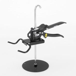


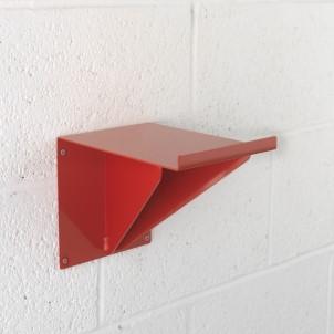
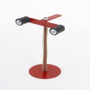


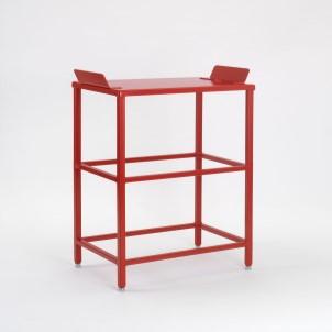


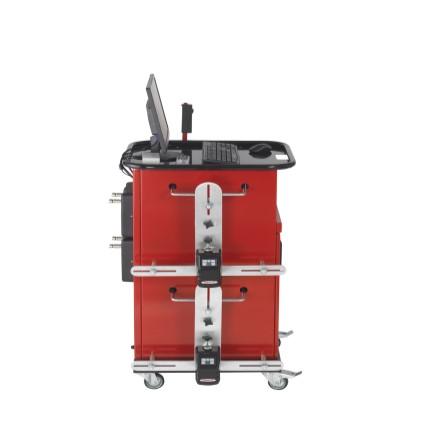
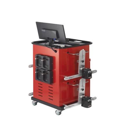
2 Our Tracking Guage Single Steer Rear Flag - Car Turn Table Car Aligner Car Aligner Car Aligner Car Aligner Car Turn Table Car Brake Peddle Depressor Horizontal Bracket Deluxe Steering Wheel Clamp Steering Wheel Clamp Vertical Cabinet Steering Wheel Level Truck Twin Steer Table - Large Table - Small Rear Flag - Truck 2 15
3 Training QuickTrak Wheel Alignment Ltd offers certificated training courses for those customers new to wheel alignment or the advanced programmes for the more capable technician. This type of training is ideal for businesses such as accident repair centres, car manufacturers, insurance companies, colleges, fast fit centres and general garages. Training is available for group courses or on a one to one basis. These are held either at our purpose designed training rooms or at your premises. Course subjects cover product training or wheel alignment theory. These course are not just limited to QuickTrak customers, we offer an independent service to all those who wish to develop their understanding of the subject. In house training offers uninterrupted time allowing full concentration. Wheel Alignment a quick guide Wheel alignment, sometimes referred to as Tracking (Europe) or Breaking (North America), is part of standard automobile maintenance. The procedure consists of adjusting the geometric angles of the vehicles road wheels so that they are set to the car maker's specification. These geometric angles (Toe, Camber & Castor) move out of Manufactures tolerance ratings through normal wear and tear & steering component replacement. Wheel alignment should be measured using QuickTrak alignment gauges at least once a year as preventative maintenance. The purpose of these adjustments is primarily to reduce excessive/premature tyre wear; and to ensure that the vehicle s road wheels travel in a straight and true manner. Service QuickTrak has a dedicated service department to support their customers in the field. They have specialist engineers in fully equipped service vans. Maintenance contracts are available to take away the worry of service and repair, leaving customers free to concentrate on their business. QuickTrak constantly monitors customers equipment making sure it is running at optimum efficiency. Primary angles Primary Angle(s) is the basic overall alignment of the road wheels in relation to each other and to the cars body/chassis. Primary Angles are: TOE CAMBER CASTER (Note: On some cars, not all of these angles are adjustable on every wheel. Caster is for steer wheels only) 14 3
 Toe curve change (left & right) Track width difference Wheelbase difference Rear Toe Adjustments Place the turn plates under the REAR wheels and place the flags on the front")

 Setback is the difference between right side and left side wheelbase length.")
4 Secondary angles The secondary angles include numerous other adjustments, such as: SAI (Steering Axis Inclination) (left & right) Included angle (left & right) Toe out on turns (left & right) Maximum Turns (left & right) Toe curve change (left & right) Track width difference Wheelbase difference Rear Toe Adjustments Place the turn plates under the REAR wheels and place the flags on the front wheels. Make sure the front wheels are in the straight ahead position. Place the measuring heads on the rear wheels, ensuring that the toe scales are at the rear. Front scale readings must be equal, if not use the rear wheel track adjusters to make them equal. Front ride height (left & right) Rear ride height (left & right) Frame angle When the scales are equal add both toe scales to find the total toe. If this amount is between 0mm and 2mm then generally the axle can be said to be correct. Setback (front & rear) Setback is the difference between right side and left side wheelbase length. It can also be measured as an angle. Setback less than the manufacturer specified tolerance (for example about 6mm) does not affect car handling. That's because, when the vehicle is turning, one wheel is ahead of the other by several centimetres and therefore the setback is negligible. There are even some car models with different factory setting for right and left side wheelbase length, for various design reasons. An off-spec setback may occur because of a collision or a difference between right and left caster.[2][3] NB: Toe readings are reversed when the measuring heads are on the rear wheels i.e. Toe in = Toe out and vice versa 4 13
5 Rear Toe Angle Rear wheel toe, either in or out, is always an individual measurement. Front wheel toe can be measured as a total, using a toe gauge, because the steering system will allow unequal adjustments on either side, to self-centre. With rear wheel toe however, each wheel can affect the steering as there is no compensating steering wheel for the rear axle. It is the rear wheel axle alignment that controls the steering wheel position. When adjusting rear wheels for toe-in or toe-out, each angle must be exactly equal on both sides, if not the vehicle will be steered away from its centre line by the inaccurate wheel. The rule of thumb, when making rear wheel adjustments, is to increase or decrease them to the manufacturer s settings. The vast majority of modern vehicles have a toe-in or toe-out of no more than 1mm per wheel. Over that tyre wear occurs to unacceptable levels. Wheel Alignment Wheel alignment is a geometrical setting relating to the amount that the rear axle is out of align to the front axle. If the rear is not aligned it may be steering the vehicle from the rear, which will result in what is known as crabbing. When a problem similar to the one shown in the drawing occurs, the vehicle will steer to the left, resulting in the steering wheel having to be turned to the right to counteract the rear steering force. At the same time the front wheel position adopts a set-back situation with respect of the vehicle s centre line. Should the front axle now be measured from the front only, this set-back situation will not be noticed. So to offer a full alignment service a vehicles thrust angle must be checked. So basically, rear wheel toe must be kept equal to the centre line and correctly toed in or out in order for the vehicle to handle correctly. With the onset of the front wheel drive vehicle, rear wheel toe adjustments have become more common place. It is easier to build an average tolerance body shell and trim the rear wheel alignment to suit, as opposed to tying yourself down to close tolerance body, which would give acceptable tyre wear and steering capability. 12 5
6 Front Wheel Alignment Rear Wheel Alignment Drive the vehicle onto the turn plates provided NEVER attempt to carry out a wheel alignment without positioning the vehicle correctly on the turn plates. Place the turn plates under the REAR wheels and place the flags on the front wheels. Make sure the front wheels are in the straight-ahead position. Step Four Turn the steering wheel to the straight-ahead position and lock it into the driver s seat with the spring loaded wheel clamp. Hang the rear assemblies onto the top of the rear tyres so that the horizontal bar is sitting at approximately the centre of the wheel and touching the tyre at both points. Use the spirit level on top of the gauge to achieve the 90 degree position. Place the measuring heads on the rear wheels ensuring the toe scales are at the rear. Note the front wheel reads; Example: left front wheel reads 1, right front wheel reads 4. The difference is 3 remember this figure (3 lines to the right). Take your laser measuring head and mount on the front wheel. The black locking hand screw on the assembly allows the hanger to be shortened or lengthened to suit different wheel sizes. Set the hand screw so that the hanger sits on top of the tyre and the three 40mm buttons touch the wheel rim. Check the spirit level is in the correct position and the toe scale is to the front of the vehicle. Transfer the measuring heads to the front wheels and the flags to the rear wheels. Adjust the track rod equally to give a rear scale indication of 3 lines to the right, i.e. 1.5 lines on either scale. The steering wheel is now set to the vehicle thrust line. Step Five Switch on each control panel so that the laser hits the rear scale. Check the number on each scale then add the readings together and divide by 2. For example, nearside reads 3, offside reads 5 so the reading for each side in this example needs to be 4 Adjust each track rod end to achieve required reading. Step Six When both rear scales are equal front wheels are aligned. 6 11
7 Front Wheel Set-back Measurement Drive the vehicle onto the turn plates provided. Front Toe Toe angle, also referred to as tracking, relates to the way in which the actual width of the wheel track varies between the front edges when compared to the rear edges of an axle s wheels. Turn the steering wheel to the straight-ahead position and lock it into the driver s seat with the spring loaded wheel clamp. Take your laser measuring head and mount on the front wheels Check the spirit level is in the correct position and the toe scale is to the front of the vehicle. Step Four Using the bottom scale labelled SETBACK you can record the readings for near and offside of the vehicle a reading of above 10mm will require further investigation. As viewed from above, the front road wheels will either be pointing towards the centre line or away from it. If the wheels point away from the centre line, they are said to be toed-out (also called a negative toe); in specification books this will be represented by a number preceded by a minus sign. Wheels pointing towards the centre line, (as shown in the diagram) are toed-in (positive toe). In this simple front only situation, the steering wheel position is shown set at right angles to the centre line, and each front wheel equally set toed in to centre line, with the rear wheels parallel. Toe angle is built into vehicle geometry to reduce the tyre wear to a minimum and to counteract any tension built in by the other angles. Ideally once the vehicle starts moving forward, forces in the suspension and drive should pull the wheels almost parallel. However most vehicles today will be set to have slight toe-in or toe-out, this is a result of vehicle designers compromising; for example, setting the wheels to toe-in provides better straight-line stability whereas setting to toe-out offers a quicker steering response. 10 7
8 Front Toe Adjustment Front Wheel Set-back Each toe scale is made up of two colours, green for toe-in and red for toe-out. When the laser hits the toe scale if both colours are the same then add the readings together; Example: 2 green and 1 red means the axle is 3mm toe-in, 2 red and 1 green means 3mm toe-out. If the readings are different colours then subtract the lower from the higher; Example: 2 green and 1 red means the axle is 1mm toe-in. After calculating the total toe and obtaining your reading adjust each track rod end by looking at the rear scale, making sure that the rear scale readings remain equal; Example: Each rear scale reading is 4, your total toe scales is 1mm toe-in and you require total toe to be 3mm toe-in. Adjust each track rod increasing the rear scales to 4.5 or 5 on each side until you arrive at the desired toe on the scale. You must keep the readings on the rear scales the same at all times. If you require less toe on the axle then reduce the numbers on the rear scales, keeping them both equal. Front wheel set-back is a check used to determine the position of the front wheels with reference to a line placed perpendicular to the vehicle s centre line. Ideally the left hand wheel should be located directly opposite the right hand wheel. However, a tolerance of 5mm is allowed on all new cars, it s acceptable on older cars to have a set-back of 10mm. Whilst conducting a routine toe check on vehicles, noting any excessive set back provides a good indicator, which suggests closer inspection is required as collision damage or suspension problems may be present. Please note: most alignment equipment does not tell you which wheel is at fault, just that there is a difference across the centre line. However positive set-back indicates that the right hand wheel is set-back further than the left. Negative set-back indicates that the left hand wheel is set-back further than the right. If the vehicle has power steering then run the engine at this point, then lock up the track rod ends. 8 9
Basic Wheel Alignment Techniques
 Basic Wheel Alignment Techniques MASTERING THE BASICS: Modern steering and suspension systems are great examples of solid geometry at work. Wheel alignment integrates all the factors of steering and suspension
Wheel Alignment Fundamentals
 CHAPTER 67 Wheel Alignment Fundamentals OBJECTIVES Upon completion of this chapter, you should be able to: Describe each wheel alignment angle. Tell which alignment angles cause wear or pull. KEY TERMS
ATASA 5 th. Wheel Alignment. Please Read The Summary. ATASA 5 TH Study Guide Chapter 47 Pages: Wheel Alignment 64 Points
 ATASA 5 TH Study Guide Chapter 47 Pages: 1403 1423 64 Points Please Read The Summary Before We Begin Keeping in mind the Career Cluster of Transportation, Distribution & Logistics Ask yourself: What careers
Camber Angle. Wheel Alignment. Camber Split. Caster Angle. Caster and Ride Height. Toe Angle. AUMT Wheel Alignment
 AUMT 1316 - Wheel Alignment 11/15/11 Camber Angle Wheel Alignment Donald Jones Brookhaven College Camber Split Camber is the amount that the centerline of the wheel tilts away from true vertical when viewed
GENERAL INFORMATION. Wheel Alignment Theory & Operation
 Fig. 1: Checking Steering Linkage GENERAL INFORMATION Wheel Alignment Theory & Operation ADJUSTMENTS NOTE: This article is intended for general information purposes only. This information may not apply
ELECTRONIC CHASSIS ALIGNMENT
 SUSPENSION Steering and Wheel Alignment - Repair Instructions - X6 ELECTRONIC CHASSIS ALIGNMENT 32... OVERVIEW OF STEERING Fig. 1: Overview Of Steering 32... OVERVIEW OF ACTIVE FRONT STEERING Fig. 2: Overview
Fiat - Argentina - Wheel Aligner / Headlamp Aimer #16435
 2017 Fiat - Argentina - Wheel Aligner / Headlamp Aimer #16435 Wheel Aligner / Headlamp Aimer Operation & Maintenance Manual Overview Fori Automation Version 1.2 4/21/2017 TABLE OF CONTENTS Section 1.0
Wheel Alignment And Diagnostic Angles (STE04)
") Module 1 Wheel Alignments Wheel Alignment And Diagnostic Angles (STE04) Wheel Alignments o Conditions Requiring An Alignment o Conditions Requiring An Alignment (cont d) o Why We Do Checks And Alignments
Module 1 Wheel Alignments Wheel Alignment And Diagnostic Angles (STE04) Wheel Alignments o Conditions Requiring An Alignment o Conditions Requiring An Alignment (cont d) o Why We Do Checks And Alignments
STEERING SYSTEM Introduction
 STEERING SYSTEM Introduction The steering makes it possible to change direction. The steering must be reliable and safe; there must not be too much play in the steering. It must be possible to steer accurately.
WHEEL ALIGNMENT SPECIFICATIONS & PROCEDURES
 WHEEL ALIGNMENT SPECIFICATIONS & PROCEDURES 1988 Jeep Cherokee 1988 Wheel Alignment INTRODUCTION PRE-ALIGNMENT VEHICLE CHECKS Prior to making wheel alignment adjustments, check and adjust the following
Why do cars need Alignment
 Why do cars need Alignment The main purpose of wheel alignment is to make the tires roll without Scuffing, slipping, or dragging under all operating conditions. Caster Camber Toe Steering axis inclination
The WHAT and WHY of. Toe Caster - Camber Kingpin Inclination - Thrust Angle Steering Angle Wheel setback
 The WHAT and WHY of Toe Caster - Camber Kingpin Inclination - Thrust Angle Steering Angle Wheel setback WHEEL ALIGNMENT SIMPLIFIED Wheel alignment is often considered complicated and hard to understand
Wheel Alignment VISUALINER 3D ARAGO SC
 Wheel Alignment VISUALINER 3D ARAGO SC Worlds First Self Calibrating Alignment System REVOLUTIONARY LIFT SYNCHRONIZATION THE NEW V3D ARAGO SC TM The V3D ARAGO advances Error-Free alignment technology with
Wheel Alignment Defined
 Wheel Alignment Defined While it's often referred to simply as an "alignment" or "wheel alignment," it's really complex suspension angles that are being measured and a variety of suspension components
BASIC WHEEL ALIGNMENT
 BASIC WHEEL ALIGNMENT You have got to know all the angles. Correct wheel alignment plays a huge part in a customer s positive driving experience. Having it dialed in correctly is essential to proper vehicle
ALIGNING A 2007 CADILLAC CTS-V
 ALIGNING A 2007 CADILLAC CTS-V I ll describe a four-wheel alignment of a 2007 Cadillac CTS-V in this document using homemade alignment tools. I described the tools in a previous document. The alignment
Hub Stands -- VERSION 5.0
 Hub Stands -- VERSION 5.0 Thanks for choosing our Alignment Hub Stands for your chassis setup needs. We hope you'll find them as handy, accurate, and easy to use as we do! Each stand has a max capacity
WHEEL ALIGNMENT Basics
 WHEEL ALIGNMENT Basics Bernhard Hoffmann Business Unit Manager Wheel Service 19. November 2013 1 Die NUSSBAUM Gruppe Wheel alignment what for? When and why is a wheel alignment necessary? The complete
Unit 3. The different types of steering gears are as follows:
 Steering Gears One of the important human interface systems in the automobile is the steering gear. The steering gear is a device for converting the rotary motion of the steering wheel into straight line
How to Set the Alignment on Ford Mustangs
 How to Set the Alignment on 1967-1973 Ford Mustangs Let's Get This Straight - Mustang Monthly Magazine Christopher Campbell Technical Editor March 25, 2015 Frontend alignment is one of the most basic adjustments
2004 SUSPENSION. Wheel Alignment - Corvette. Caster Cross +/ / Fastener Tightening Specifications Specification Application
 2004 SUSPENSION Wheel Alignment - Corvette SPECIFICATIONS WHEEL ALIGNMENT SPECIFICATIONS Wheel Alignment Specifications Camber Cross Caster Cross Suspension Camber Tolerance Caster Tolerance FE1 & FE3
1940 Hudson SERVICING THE FRONT SUSPENSION SYSTEM
 1940 Hudson SERVICING THE FRONT SUSPENSION SYSTEM Source of this material is from 1940 Series, Issue 3, November-December Hudson Service Magazine SERVICING THE FRONT SUSPENSION SYSTEM No set rule can be
The best thing to happen to Wheel Alignment since... The Wheel.
 The best thing to happen to Wheel Alignment since... The Wheel www.quicktrak.co We d like you to know... QuickTrak Wheel Aligners are hand-made in Sheffield, England. The quality is there for all to see,
Wheel Alignment - Basics
 Service Training Self Study Program 860103 Wheel Alignment - Basics Volkswagen Group of America, Inc. Volkswagen Academy Printed in U.S.A. Printed 2/2012 Course Number 860103 2012 Volkswagen Group of America,
Suspension and Steering Alignment
 Suspension and Steering Alignment Matthew Whitten Brookhaven College Alignment Components Ride height Caster Camber Included angle Scrub radius Thrust angle Toe Turning radius Toe out on turns Steering
INSTRUCTIONS FOR STRUT FRONT, 4-LINK REAR, 1 5/8 FRAME, FULL SIZE, 4130 ELIMINATOR CHASSIS
 #917230 Page 1 of 6 7230 INSTRUCTIONS FOR STRUT FRONT, 4-LINK REAR, 1 5/8 FRAME, FULL SIZE, 4130 ELIMINATOR CHASSIS ITEM QTY SIZE/PART NO. TUBE CODE DESCRIPTION 1 2 4350 Cage Side 2 2 4351 Forward strut
Adjustable Tie-rod Ends (Mm5TR-1)
") 3430 Sacramento Dr., Unit D San Luis Obispo, CA 93401 Telephone: 805/544-8748 Fax: 805/544-8645 www.maximummotorsports.com 2005-10 Adjustable Tie-rod Ends (Mm5TR-1) 3. Remove the front wheels. 4. Loosen
3430 Sacramento Dr., Unit D San Luis Obispo, CA 93401 Telephone: 805/544-8748 Fax: 805/544-8645 www.maximummotorsports.com 2005-10 Adjustable Tie-rod Ends (Mm5TR-1) 3. Remove the front wheels. 4. Loosen
Hunter Alignment. This alignment education series also helps prepare technicians for the ASE A4 Certification.
 Hunter Alignment Hunter offers entry and intermediate level alignment courses throughout the county. The combination of discussion and hands-on lab/shop activities melds theory with reality. This alignment
"Top Ten" reasons to measure: 10. To Provide Proper Sheet Metal Fit
 Important Reasons why your collision shop needs to Measure. This is one of the most important functions of collision repair and it is a Must Do Process for the success of your business. by Tom Brandt Whether
INSTRUCTIONS FOR USE CONTENTS. I /18 - Ver. 00 CAUTION! 3 GENERAL WARNINGS 3 PRECAUTIONS AND INSTRUCTIONS FOR SAFETY, USE AND MAINTENANCE 3
 INSTRUCTIONS FOR USE I CONTENTS CAUTION! 3 GENERAL WARNINGS 3 PRECAUTIONS AND INSTRUCTIONS FOR SAFETY, USE AND MAINTENANCE 3 1 - MACHINE DESCRIPTION 5 1.1 - TECHNICAL DATA 5 2 - PROGRAM FLOW 6 2.1 - HOW
Part 3: CHECKING TOE ANGLE -
 CHECKING TOE ANGLE - Part 3: With the caster and camber out of the way and the vehicle on a properly leveled surface, it's time to lay out the string network that will allow you to take accurate measurements
DIAGNOSIS AND TESTING
 DIAGNOSIS AND TESTING SUSPENSION AND STEERING SYSTEM 2007 SUSPENSION Suspension - Nitro CONDITION POSSIBLE CAUSES CORRECTION FRONT END NOISE 1. Loose or worn wheel bearings. 1. Replace wheel bearings.
Global West Suspension 655 South Lincoln Ave San Bernardino Ca Phone Fax Web address globalwest.
 Global West Suspension 655 South Lincoln Ave San Bernardino Ca. 92408 Phone 877-470-2975 Fax 909-890-0703 Web address globalwest.net Mustang coilover instruction sheets for 64-66 Kit includes the following
ON ROAD SETUP GUIDE PART ONE
 PART ONE Ride height is adjusted by the preload of the spring collars. Winding them down will raise the ride height, while winding them up will decrease the ride height. It is important to note that adjusting
Hunter Alignment. The following courses are available. Read descriptions of each on the pages that follow.
 Hunter Alignment Two to five day courses for both entry-level and seasoned technicians who need wheel alignment training. Hunter Alignment courses are presented across the country. The following courses
CRUISEMASTER CRS INDEPENDENT COIL SUSPENSION
 WHY INDEPENDENT SUSPENSIONS? Beam axles have passed the test of time and are generally a good workhorse. However, you don't see them any more on cars. Why is this? The first reason is geometry. That is
2011+ Adjustable Tie-rod Ends (Mm5TR-2)
") 3430 Sacramento Dr., Unit D San Luis Obispo, CA 93401 Telephone: 805/544-8748 Fax: 805/544-8645 www.maximummotorsports.com 2011+ Adjustable Tie-rod Ends (Mm5TR-2) Instructions 1. Set the parking brake
3430 Sacramento Dr., Unit D San Luis Obispo, CA 93401 Telephone: 805/544-8748 Fax: 805/544-8645 www.maximummotorsports.com 2011+ Adjustable Tie-rod Ends (Mm5TR-2) Instructions 1. Set the parking brake
AXLE ALIGNMENT ZF (40 FT)
") SECTION 04-000.10 04-000.10/ 1 2010DE06 GENERAL CONDITIONS See Figures 1 and 2 for the geometry of the frontand rear axles. Figure 3 represents the axis system of a Nova LFS 40-ft bus. Before performing
SECTION 04-000.10 04-000.10/ 1 2010DE06 GENERAL CONDITIONS See Figures 1 and 2 for the geometry of the frontand rear axles. Figure 3 represents the axis system of a Nova LFS 40-ft bus. Before performing
Hub Stands -- VERSION 5.0
 Hub Stands -- VERSION 5.0 Thanks for choosing our Alignment Hub Stands for your chassis setup needs. We hope you'll find them as handy, accurate, and easy to use as we do! Each stand has a max capacity
INTRO/APPLICATIONS PARTS TOOLS ACCESSORIES BRAKE & CV SPC GEAR & INDEXES APPLICATIONS PARTS
 TABLE OF CONTENTS INTRO/.................. 2-39 How to Use the Sourcebook......................................2 How to Sell Alignment...........................................2 Training Resources..............................................3
AUTOMOTIVE GARAGE EQUIPMENT
 AUTOMOTIVE GARAGE EQUIPMENT KWA-300 3D technology wheel aligner for car LAUNCH The 3D Wheel Aligner with 4 digital cameras, targets without on-board electronic and premium PC with Windows XP operation
7333 INSTRUCTIONS FOR MILD STEEL A-ARM AVENGER CHASSIS MUSTANG
 #917333 Page 1 of 5 7333 INSTRUCTIONS FOR MILD STEEL A-ARM AVENGER CHASSIS 1994-2004 MUSTANG ITEM QTY PART NO/SIZE TUBE CODE DESCRIPTION 1 1 4080 Main hoop 2 1 pr 4180 Cage side (driver & passenger side)
INSTRUCTIONS FOR STRUT FRONT, 4-LINK REAR, ROADSTER CHASSIS
 #917406 Page 1 of 5 7406 INSTRUCTIONS FOR STRUT FRONT, 4-LINK REAR, ROADSTER CHASSIS ITEM QTY SIZE/PART NO. TUBE CODE DESCRIPTION 1 1 4215 Front frame rail strut 1 5/8 (pair) 2 1 4236 Roadster firewall
2. Remove front wheels.
 Read all instructions before beginning work. Following instructions in the proper sequence will ensure the best and easiest installation. Thank you for purchasing Maximum Motorsports Caster/Camber Plates.
Wrenching with Rob - Chassis Alignment Basics
 Wrenching with Rob - Chassis Alignment Basics By Dr. Rob Tuluie, PhD Editor's Note--This story is part of the "Wrenching with Rob" series, in which Vintage Editor and Technical Writer Dr. Robin Tuluie
Unit No.03 Front axle, Steering system, Rear axle, Wheel & Tyres
 Unit No.03 Front axle, Steering system, Rear axle, Wheel & Tyres Prepared by, Prof. Santosh Kailas Chandole ME (Design Engineering) BE (Automobile Engineering) Steering system STEERING REQUIREMNTS: It
(d) The magnetic field lines, produced around a straight current-carrying conductor, are concentric circles. Their centres lie on the wire.
 The magnetic field lines, produced around a straight current-carrying conductor, are concentric circles. Their centres lie on the wire.") Page 240»Exercise» Question 1: Which of the following correctly describes the magnetic field near a long straight wire? (a) The field consists of straight lines perpendicular to the wire (b) The field
Page 240»Exercise» Question 1: Which of the following correctly describes the magnetic field near a long straight wire? (a) The field consists of straight lines perpendicular to the wire (b) The field
Welcome! mhtml:file://c:\newgti\technical Resources\SmartCamber Manual.mht
 Page 1 of 8 Welcome! Thank you for your purchase of our SmartCamber tool with the SmartTool digital module. You are now the owner of what we believe is the best portable camber and caster measuring tool
UNIMECK. Presents Truck Wheel Equipments. We Are The Leading Manufactures. Of Garage Equipments...
 UNIMECK TM Tyre Service Equipment Pvt. Ltd. We Are The Leading Manufactures Of Garage Equipments... Presents Truck Wheel Equipments www.unimeckauto.com Heavy Vehicles/Truck & Bus Wheel Balancer Features:
A double-wishbone type suspension is used in the front. A multi-link type suspension is used in the rear. Tread* mm (in.) 1560 (61.
 1560 (61.") CHASSIS SUSPENSION AND AXLE CH-69 SUSPENSION AND AXLE SUSPENSION 1. General A double-wishbone type suspension is used in the front. A multi-link type suspension is used in the rear. 08D0CH111Z Specifications
CHASSIS SUSPENSION AND AXLE CH-69 SUSPENSION AND AXLE SUSPENSION 1. General A double-wishbone type suspension is used in the front. A multi-link type suspension is used in the rear. 08D0CH111Z Specifications
TRUCK AND BUS TYRE I TECHNICAL MANUAL MAINTENANCE AND CARE
 TRUCK AND BUS TYRE I TECHNICAL MANUAL MAINTENANCE AND CARE About tyre inflation Truck alignment and tyre wear Tyre damage TECHNICAL INFORMATION MAINTENANCE AND CARE About tyre inflation ONE OF THE MOST
Installation Guide for the TJ Long-Arm Suspension System Kit (STL)
") INSTALLATION GUIDE Tera Manufacturing, Inc. 5251 South Commerce Dr. Murray, Utah 84107 Phone/801.288.2585 Fax/801.713.2313 www.teraflex.biz Installation Guide for the TJ Long-Arm Suspension System Kit
INSTALLATION GUIDE Tera Manufacturing, Inc. 5251 South Commerce Dr. Murray, Utah 84107 Phone/801.288.2585 Fax/801.713.2313 www.teraflex.biz Installation Guide for the TJ Long-Arm Suspension System Kit
7256 INSTRUCTIONS FOR ELIMINATOR II A-ARM FRONT, 4-LINK REAR, MILD STEEL, INTERMEDIATE, SERIES CHASSIS
 #917256 Page 1 of 7 7256 INSTRUCTIONS FOR ELIMINATOR II A-ARM FRONT, 4-LINK REAR, MILD STEEL, INTERMEDIATE, SERIES CHASSIS ITEM QTY SIZE/PART NO. TUBE CODE DESCRIPTION 1 2 4138 Cage Side 2 2 4208 Forward
Ravaglioli TD1760WS Wheel Alignment System. Operational Procedures
 Ravaglioli TD1760WS Wheel Alignment System Operational Procedures SAFELY TURNING ON AND TURNING OFF THE SYSTEM This is the program s main screen. To turn on the program- Set rocker switch on rear of cabinet
SUSPENSION 2-1 SUSPENSION TABLE OF CONTENTS
 DN SUSPENSION 2-1 SUSPENSION TABLE OF CONTENTS page ALIGNMENT... 1 FRONT SUSPENSION - 4x2... 6 page FRONT SUSPENSION - 4x4... 14 REAR SUSPENSION... 23 ALIGNMENT TABLE OF CONTENTS page AND OPERATION WHEEL
Preventive Maintenance Become 100% competitive.
 Contact 560 Bond St. Lincolnshire, IL 60069 Tel. (888) 282-1336 www.gfac.com/us Preventive Maintenance Become 100% competitive. Achieve more... Do you know? 70% of machine downtime is due to maintenance
AUTO PRODUCT OVERVIEW. Save fuels, tyres & much more...
 AUTO PRODUCT OVERVIEW Save fuels, tyres & much more... JOSAM AB, Sweden is the global expertise in commercial vehicles wheel alignment & collision repair systems with 40years experience. We have wide range
7260 INSTRUCTIONS FOR ELIMINATOR II STRUT FRONT, 4-LINK REAR, MILD STEEL, FULL SIZE, SERIES CHASSIS
 #917260 Page 1 of 6 7260 INSTRUCTIONS FOR ELIMINATOR II STRUT FRONT, 4-LINK REAR, MILD STEEL, FULL SIZE, SERIES CHASSIS ITEM QTY SIZE/PART NO. TUBE CODE DESCRIPTION 1 2 4139 Cage Side 2 2 4250 Forward
Design of Suspension and Steering system for an All-Terrain Vehicle and their Interdependence
 Design of Suspension and Steering system for an All-Terrain Vehicle and their Interdependence Saurabh Wanganekar 1, Chinmay Sapkale 2, Priyanka Chothe 3, Reshma Rohakale 4,Samadhan Bhosale 5 1 Student,Department
Wide Band EFIE Installation Instructions. Locate the wide band oxygen sensor current wire
 Wide Band EFIE Installation Instructions Install your fuel efficiency device The EFIE is not intended to be a fuel saver by itself. You should install a device that is designed to get more energy out of
2. MEASURE VEHICLE HEIGHT. (b) Measure the vehicle height. Measurement points: C: Ground clearance of front wheel center
 Measure the vehicle height. Measurement points: C: Ground clearance of front wheel center") ADJUSTMENT If the wheel alignment has been adjusted, and if suspension or underbody components have been removed/installed or replaced, be sure to perform the following initialization procedure in order
ADJUSTMENT If the wheel alignment has been adjusted, and if suspension or underbody components have been removed/installed or replaced, be sure to perform the following initialization procedure in order
US Patent You will find many features that set our Caster/Camber Plates apart from the rest.
 3430 Sacramento Dr., Unit D San Luis Obispo, CA 93401 Telephone: 805/544-8748 Fax: 805/544-8645 www.maximummotorsports.com US Patent 6485223 Read all instructions before beginning work. Following instructions
Setup Guide and Chassis Tuning Tips (simple version) By Jim Daniels
 By Jim Daniels") This document is released into the public domain and may be reproduced and distributed in its entirety so long as all credit to Jim Daniels remains. If you find this guide helpful please consider donating
This document is released into the public domain and may be reproduced and distributed in its entirety so long as all credit to Jim Daniels remains. If you find this guide helpful please consider donating
VCO-K. True Italian Style. VIDEOLOGIC CONCEPT-K WHEEL ALIGNERS. videologic SOMEONE YOU CAN TRUST VCO-K.WINTRAX.VAPE
 VIDEOLOGIC CONCEPT-K VCO-K WHEEL ALIGNERS True Italian Style. Cod. V297.002 - Edition 1 - February 2016 VCO-K.WINTRAX.VAPE videologic SOMEONE YOU CAN TRUST VIDEOLOGIC CONCEPT-K VCO-K PERSONAL COMPUTER
TRADE OF HEAVY VEHICLE MECHANIC
 TRADE OF HEAVY VEHICLE MECHANIC PHASE 2 Module 8 Steering and Suspension Systems UNIT: 2 Table of Contents 1.0 Learning Outcome... 1 1.1 Key Learning Points... 1 2.0 Health and Safety... 3 3.0 The Function
Phase. Trade of Motor Mechanic. Module 7. Unit 3. Steering, Alignment & Geometry
 Phase 2 Trade of Motor Mechanic Module 7 Unit 3 Steering, Alignment & Geometry Produced by In cooperation with: Subject Matter Experts Martin McMahon & CDX Global Curriculum Revision 2.2 16-01-07 SOLAS
GR40 SLA Installation and Set Up Instructions.
 GR40 SLA Installation and Set Up Instructions. Read these instructions completely before beginning. These instructions are written for experienced installer/technicians with a strong idea as to how a chassis
Participant 's Manual Basic principles Chassis
 Participant 's Manual Basic principles Chassis BMW Service Aftersales Training conceptinfo@bmw.de 2004 BMW Group München, Germany. Reprints of this manual or its parts require the written approval of BMW
FADA Certified Technician Exam Specifications
 1 Overview This study guide is intended to help students in Florida automotive programs study for the FADA Certified Technician exam. This guide contains test specifications, a task list, and sample questions.
Suspension Supplement Inboard Anti Roll Bar
 Suspension Supplement Westfield Sportscars Ltd Unit One Gibbons Industrial Park Dudley Road Kingswinford West Midlands DY6 8XF www.westfield-sportscars.co.uk Tel: +44 (0) 1384 400077 Fax: +44 (0) 1384
1 of 9 7/24/2014 9:02 PM
 1 of 9 7/24/2014 9:02 PM Four-Wheel Alignment Special Service Tools 204-805 CAUTION: Make sure the vehicle is on a flat level surface. CAUTION: Make sure the tire pressures are within specification. CAUTION:
DIY balancing. Tony Foale 2008
 DIY balancing. Tony Foale 2008 I hope that the main articles on the theory behind engine balance have removed the mystic which often surrounds this subject. In fact there is no reason why anyone, with
Customer Engagement - Execution Playbook Module 1 WHEEL ALIGNMENTS ALIGNMENTS
 Customer Engagement - Execution Playbook Module 1 WHEEL ALIGNMENTS -------------------------- ALIGNMENTS 101 ------------------------------ While a wheel alignment is often referred to simply as an alignment,
APPENDIX A: Background Information to help you design your car:
 APPENDIX A: Background Information to help you design your car: Solar Cars: A solar car is an automobile that is powered by the sun. Recently, solar power has seen a large interest in the news as a way
Chicane Coilover Kit For '64 to '72 Chevelle/ A Body. Installation Instructions
 Nov 3, 2017 Chicane Coilover Kit For '64 to '72 Chevelle/ A Body Installation Instructions Actual parts may vary from photo depending on application. 1 P a g e The following instructions are intended for
Technical Support Line: (952) Fax Line: (952) Hanover Ave. Lakeville, MN
 Fax Line: (952) Hanover Ave. Lakeville, MN") Technical Support Line: (952) 985-5675 Fax Line: (952) 985-5679 21730 Hanover Ave. Lakeville, MN 55044 www.qa1.net INSTALLATION INSTRUCTIONS QA1 P/N CC104MU Camber Caster Plates 1994-2004 Mustang 5.0/4.6
Technical Support Line: (952) 985-5675 Fax Line: (952) 985-5679 21730 Hanover Ave. Lakeville, MN 55044 www.qa1.net INSTALLATION INSTRUCTIONS QA1 P/N CC104MU Camber Caster Plates 1994-2004 Mustang 5.0/4.6
Real Square RSX User Instructions v. 10.2
 Real Square RSX User Instructions v. 10.2 Basic RSX Kit Contents: (1) RSX Shaft Mounted Laser Assembly (2) Axle Alignment Fixtures (Hub Mount or Spindle Thread-on Mount) (2) Wheel Measurement Fixtures
Typical mounting of a dial indicator for a radial check. Moog Automotive, Inc.
 Inspect / Service / Test / Replace To find out if the ball joint is loose beyond manufacturer's specifications, use an accurate measuring device. Most load carrying ball joints have a wear limit of 0.060"
Design, Modelling & Analysis of Double Wishbone Suspension System
 Design, Modelling & Analysis of Double Wishbone Suspension System 1 Nikita Gawai, 2 Deepak Yadav, 3 Shweta Chavan, 4 Apoorva Lele, 5 Shreyash Dalvi Thakur College of Engineering & Technology, Kandivali
Application Date : April 8, No. 9346/25. Complete Left : Dec, 31, Complete Accepted ; July 8, 1926,
 PATENT SPECIFICATION Application Date : April 8, 1925. No. 9346/25. 254,414 Complete Left : Dec, 31, 1925. Complete Accepted ; July 8, 1926, PROVISIONAL SPECIFICATION. Improvements in Axle Suspension for
INSTALLATION GUIDE Avenger 4-Link, Scalloped for 1-5/8 Clips and Chassis
 INSTALLATION GUIDE 6260 Avenger 4-Link, Scalloped for 1-5/8 Clips and Chassis WARRANTY NOTICE: There are NO WARRANTIES, either expressed or implied. Neither the seller nor manufacturer will be liable for
Multilink IRS Setup & Assembly Manual
 Art Morrison Enterprises Multilink IRS Setup & Assembly Manual 8/13/2018 Rev 6 Contents Introduction... 3 Toe Link Eccentric... 3 Powdercoating... 3 IRS Assembly Steps... 4 1. Backing plates/knuckles/hubs...
Minimising Bump Steer in the TR
 Minimising Bump Steer in the TR Bump Steer is when your wheels steer themselves without input from the steering wheel. The undesirable steering is caused by bumps in the road interacting with improper
FEATURES. Three adjustable threaded feet allow easy level adjustment
 FEATURES Center axle is specially ground to be perfectly straight & level with ends additionally hand ground for precision fitment into bearings Manually-selected ball-bearings are precisely pressed into
Over The Knuckle Steering PART #: RS-SC300-UV APPLICATION: XJ,TJ,ZJ
 Rusty s Off-Road Products 7161 Steele Station Road Rainbow City, AL 35906 Phone: (256) 442-0607 FAX: (256) 442-0017 Web Site: www.rustysoffroad.com Over The Knuckle Steering PART #: RS-SC300-UV APPLICATION:
ROLL CENTER You can adjust the front and rear roll centers of the XB8 by changing the mounting locations of various components.
 Your XRAY XB8 luxury nitro buggy is a top competition, precision racing machine that features multiple adjustments that allow you to set up for any track condition. The XB8 includes innovative set-up features
Jeep Wrangler Toe-in and Steering Wheel Center Adjustment
 Jeep Wrangler Toe-in and Steering Wheel Center Adjustment There are really only two adjustments that are adjustable on the front of 1997-2006 Jeep Wranglers. The first is caster, and that is only adjustable
Installation Instructions
 Instructions Created by an: DIY Alignment Toe Set Tool, 5 Patterns (SKU# DIY-TST) Installation Instructions CAUTION: Safety glasses should be worn at all times when working with vehicles and related tools
KS3 Revision. 8J Magnets and Electromagnets
 KS3 Revision 8J Magnets and Electromagnets 1 of 29 Boardworks Ltd 2007 Contents 8J Magnets and Electromagnets Magnetic materials Magnetic fields Electromagnets Summary activities 2 of 29 Boardworks Ltd
DODGE OFF ROAD T-STYLE STEERING KIT INSTALLATION INSTRUCTIONS
 Dodge Off Road, LLC Specializing in Dodge Ram Solid-Axle 4x4 Suspension and Steering for Off Road Applications 855.9009.DOR sales@dodgeoffroad.com dodgeoffroad.com DODGE OFF ROAD T-STYLE STEERING KIT INSTALLATION
RZR 900 spring/shock installation
 RZR 900 spring/shock installation Thank you for purchasing the Shock Therapy Dual Rate Spring Kit for your RZR 900. Your item list: 2 Front upper coil springs, 2 Front lower coil springs, 2 Rear upper
REAR UPPER CONTROL ARM
 CHE PERFORMANCE PRODUCTS INSTALLATION INSTRUCTIONS REAR UPPER CONTROL ARM CHE2K: Tubular Upper: 2005-2010 Mustang CHE2L: Street/Strip Adjustable Upper: 2005-2010 Mustang CHE2M: Competition Adjustable Upper:
1. GENERAL INFORMATION
 Instructions for use I Index 1. GENERAL INFORMATION 3 1.1 - GENERAL SAFETY RECOMMENDATIONS 3 1.2 - FIELDS OF APPLICATION 4 1.3 - OVERALL DIMENSIONS 4 1.4 - TECHNICAL DATA 5 2. MOVING THE CABINET 5 3. POWER
CRUISEMASTER XT COIL - INDEPENDENT SUSPENSION SYSTEMS
 VEHICLE COMPONENTS PTY LTD A.B.N. 44 010 033 762 352b Bilsen Rd Geebung QLD 4034 PO Box 14 VIRGINIA BC QLD 4014 Accounts: 07 3624 3810 Fax 07 3624 3888 accounts@ Sales: 07 3624 3800 Fax 07 3624 3888 sales@
II YEAR AUTOMOBILE ENGINEERING AT AUTOMOTIVE CHASSIS QUESTION BANK UNIT I - LAYOUT, FRAME, FRONT AXLE AND STEERING SYSTEM
 II YEAR AUTOMOBILE ENGINEERING AT 6402 - AUTOMOTIVE CHASSIS QUESTION BANK UNIT I - LAYOUT, FRAME, FRONT AXLE AND STEERING SYSTEM 1. Write about the requirements of frame and selection of cross section
FRONT WHEEL ALIGNMENT
 2 Front: B A A Rear: C D Front SUENSION FRONT WHEEL ALIGNMENT D F046082E03 B FRONT WHEEL ALIGNMENT ADJUSTMENT 1. INECT TIRE (a) Inspect the tires (see page TW-3). 2. MEASURE VEHICLE HEIGHT Standard vehicle
'64-72 Chevelle/ A Body Rear Coilover Conversion Kit
 Nov 3, 2017 '64-72 Chevelle/ A Body Rear Coilover Conversion Kit Includes instructions for Currie Brand Axles The following instructions are intended for professional installers and are guidelines only.
Railway Technical Web Pages
 Railway Technical Web Pages Archive Page Vehicle Suspension Systems Introduction Almost all railway vehicles use bogies (trucks in US parlance) to carry and guide the body along the track. Bogie suspension
Comfort and safety when you need it most
 Comfort and safety when you need it most 1 2 Comfort and safety when you need it most Scot Seats Group, established in 2000 are UK based designers and manufacturers of specialist seating for the transportation
geoliner 680 and geoliner 780
 geoliner 680 and geoliner 780 3D wheel alignment 3D wheel alignment Accurate The high-definition cameras have a wide viewing angle. All vehicle specs are supplied directly from the OEMs and are, therefore,