Part 3: CHECKING TOE ANGLE -
|
|
|
- Jacob Bruce
- 6 years ago
- Views:
Transcription
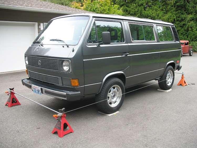
1 CHECKING TOE ANGLE - Part 3: With the caster and camber out of the way and the vehicle on a properly leveled surface, it's time to lay out the string network that will allow you to take accurate measurements off of the wheel locations in order to set the toe. These measurements are what you will use to adjust your suspension into the correct position for a proper alignment. The parts that I used for this string network are two stick of conduit (must be at least 7' long), string, four jack stands and four clamps. You will also need a quality ruler to set up the string network, but we will get to that in a minute. Starting with the two sticks of conduit, I drilled holes in each end exactly 73" apart. The exact distance is not important as long as the strings are positioned wider than the widest part of the vehicle and at least 2" wider than the distance between the outer edges of the tires. What is important is that the holes are drilled at exactly the same distance from each other. Place two jack stands at each end of the vehicle at the corner of the vehicle. Try to position each jack stand the same distance from the vehicle as the one next to it. Position each conduit piece on top of two jack stands (one front, one rear) and secure one clamp on each jack stand in such a way that it prevents the conduit from coming off of the stand but still allows the conduit to be moved side to side. With the conduit in place, you can then tie a string between each conduit through the drilled holes. Tying through the drilled holes ensures that the strings stay exactly the same distance apart. Pull the strings as taught as possible without tipping over the jack stands. Please look at the pictures below for reference while reading the above descriptions.
2
3

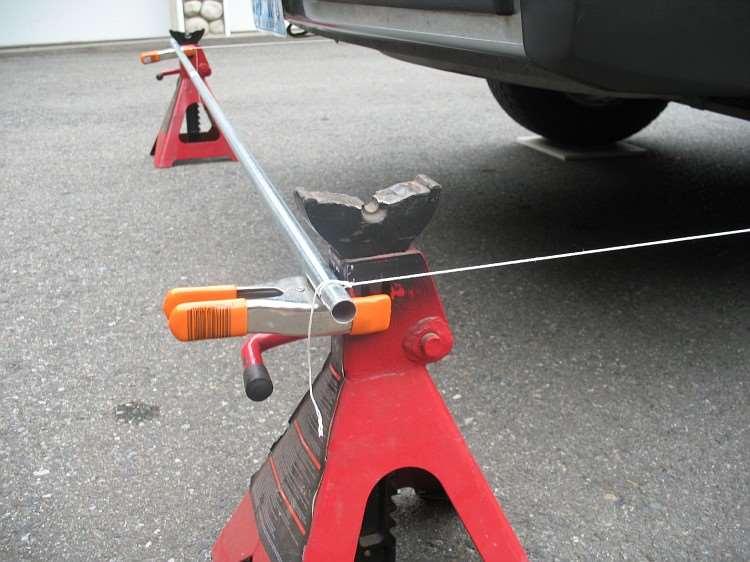
4 With the strings in place, you will now need to raise or lower the position of the conduit in order to position the string at the exact centerline of the wheel hubs. Again, use whatever means you have to accomplish this. Refer to the photos above for two different approaches.
5

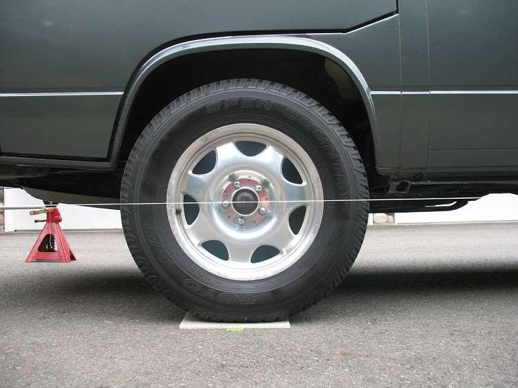
6 It is now time to square the strings with the chassis of the vehicle. People use various methods for this, but in the interest of keeping things as simple as possible, I like to measure off of the centers of the hubs. Even though it shows it in the pictures below, it is not perfectly accurate to measure off of the front grease caps. The caps are so easily damaged and distorted over time that they are not suited for precise measurements. The best practice is to remove the grease caps and measure from the end of the spindle. It's now just a simple matter of making sure that the strings are the same distance between the left and right front hubs and between the left and right rear hubs.
7 This distance will not be the same front and rear, but making the distances the same left to right will set the strings so that they are parallel with the chassis. Being parallel to the chassis is important because it helps set the thrust angle as described above. It must be noted that it may take several tries in order to get the strings sitting exactly where they should be. I like to do a quick set-up first just making sure that the strings are kind of close. That way, when I do my final settings, the movements that I do to the string at the front of the vehicle does not have too much effect on the measurement at the rear. It usually takes me about three trips around the vehicle to get it right, but if you are not paying attention or don't do an initial setting to get the strings close, you could make many more trips back and forth. It should also be noted that the string that I used has a thickness of just about 1mm. I like to use the inside edge of the string for my measurement points. String with a lot of fuzz is not going to be very helpful to you as smooth string gives you a crisp line of sight measurement.
8

9 Now we can move on to actually measuring the toe angle. Again, this is where the thrust angle can come into play. Toe angle adjustments can be performed without the use of the string jig. All it takes is a simple flat bar across each front wheel and a tape measure. Measure in front of the tire and in back of the tire. The difference is your toe angle. There are two problems with this method. One is that without the strings, when checking/setting the rear wheel toe angle, there is no way to reference to the centerline of the vehicle. This means that even though the left and right rear wheels have the correct toe angle relationship, they still could be pointing off to the left or off to the right of the vehicle s centerline.
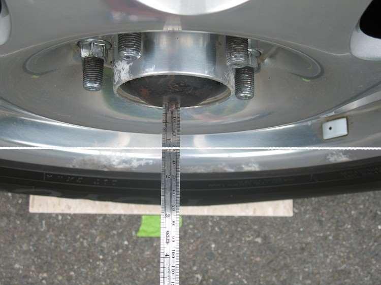
10 This would result in the vehicle going down the road like a crab as described in the definition of thrust angle. The second problem is that when checking/adjusting the toe on the front without the strings for reference, there is no way to tell where the steering wheel will be positioned relative to the wheels pointing straight ahead. While the car could still go down the road straight (assuming that the rear toe is set correctly), the steering wheel could end up way off center. Setting up the strings eliminates both of these issues. Luckily for us, the Bentley manual spells out the front wheel total toe angle in minutes, millimeters and inches and the rear toe angle is spelled out at zero minutes so as long as it measures equal, your good. Total toe needs to be divided in half to know the single wheel toe angle. The rest is all very simple. The Bentley manual describes how to center the steering wheel. Once this is done, it s a simple matter of measuring from the front lip on the wheel at string height and the rear lip on the wheel and again, the difference is your single wheel toe angle. Combine the measurement differences for the left and right wheels to know the total to angle. The pictures below show the right front toe angle at 3mm (26mm at the rear lip of the wheel and 29mm at the front lip of the wheel). Assuming that the left front wheel shows the same 3mm toe angle, this would result in a total toe angle of 6mm. An adjustment of 1mm toe out per side (or 2mm total toe out) would be needed in order to adjust the toe angle into specs. Guess I need a minor adjustment!
11

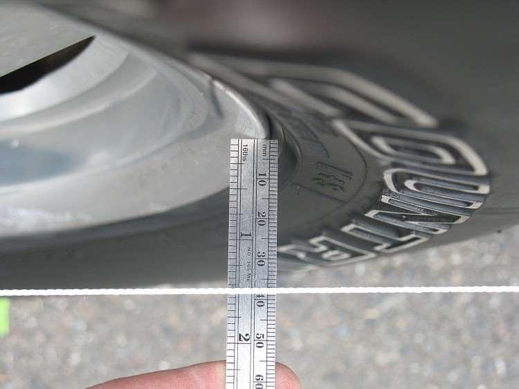
12 The pictures below show the real world measurements of the right rear wheel of my van. You can see that both front and rear lips measure 37mm (actually one of the photos looks like 37.5mm, but the ruler is angled slightly making it look that way. Taking pictures while holding rulers is hard) resulting in zero toe angle for the right rear.
13
, the rest is really very simple.")
14 That s it really! Honestly, I know that it looks like a lot because of all of words, but once you have the string jig and you purchase the RPW tool (or build the camber bar), the rest is really very simple. Any weekend warrior should be able to perform these operations without any real difficulty (frozen nuts and bolts not included) T3 Technique LLC. All Rights Reserved
Jeep Wrangler Toe-in and Steering Wheel Center Adjustment
 Jeep Wrangler Toe-in and Steering Wheel Center Adjustment There are really only two adjustments that are adjustable on the front of 1997-2006 Jeep Wranglers. The first is caster, and that is only adjustable
ALIGNING A 2007 CADILLAC CTS-V
 ALIGNING A 2007 CADILLAC CTS-V I ll describe a four-wheel alignment of a 2007 Cadillac CTS-V in this document using homemade alignment tools. I described the tools in a previous document. The alignment
Setup Guide and Chassis Tuning Tips (simple version) By Jim Daniels
 By Jim Daniels") This document is released into the public domain and may be reproduced and distributed in its entirety so long as all credit to Jim Daniels remains. If you find this guide helpful please consider donating
This document is released into the public domain and may be reproduced and distributed in its entirety so long as all credit to Jim Daniels remains. If you find this guide helpful please consider donating
INSTRUCTIONS FOR STRUT FRONT, 4-LINK REAR, 1 5/8 FRAME, FULL SIZE, 4130 ELIMINATOR CHASSIS
 #917230 Page 1 of 6 7230 INSTRUCTIONS FOR STRUT FRONT, 4-LINK REAR, 1 5/8 FRAME, FULL SIZE, 4130 ELIMINATOR CHASSIS ITEM QTY SIZE/PART NO. TUBE CODE DESCRIPTION 1 2 4350 Cage Side 2 2 4351 Forward strut
7333 INSTRUCTIONS FOR MILD STEEL A-ARM AVENGER CHASSIS MUSTANG
 #917333 Page 1 of 5 7333 INSTRUCTIONS FOR MILD STEEL A-ARM AVENGER CHASSIS 1994-2004 MUSTANG ITEM QTY PART NO/SIZE TUBE CODE DESCRIPTION 1 1 4080 Main hoop 2 1 pr 4180 Cage side (driver & passenger side)
7256 INSTRUCTIONS FOR ELIMINATOR II A-ARM FRONT, 4-LINK REAR, MILD STEEL, INTERMEDIATE, SERIES CHASSIS
 #917256 Page 1 of 7 7256 INSTRUCTIONS FOR ELIMINATOR II A-ARM FRONT, 4-LINK REAR, MILD STEEL, INTERMEDIATE, SERIES CHASSIS ITEM QTY SIZE/PART NO. TUBE CODE DESCRIPTION 1 2 4138 Cage Side 2 2 4208 Forward
7211 A-ARM FRONT, 4-LINK, 3 X 2 FRAME, INTERMEDIATE, ELIMINATOR CHASSIS ITEM QTY SIZE/PART NO. TUBE CODE DESCRIPTION
 #917211 Page 1 of 6 7211 A-ARM FRONT, 4-LINK, 3 X 2 FRAME, INTERMEDIATE, ELIMINATOR CHASSIS ITEM QTY SIZE/PART NO. TUBE CODE DESCRIPTION 1 2 4138 Cage Side 2 2 4208 Forward strut 3 1 4038 Main Hoop 4 1
Pro/Series 2000 Tubular A-Arm Front Suspension
 11 Mennonite Church Road Spring City, PA 19475 (610) 948-7303 Installation Instructions Pro/Series 2000 Tubular A-Arm Front Suspension (Pinto-Style) CAUTION!!! The most important requirement for a successful
INSTRUCTIONS FOR STRUT FRONT, 4-LINK REAR, ROADSTER CHASSIS
 #917406 Page 1 of 5 7406 INSTRUCTIONS FOR STRUT FRONT, 4-LINK REAR, ROADSTER CHASSIS ITEM QTY SIZE/PART NO. TUBE CODE DESCRIPTION 1 1 4215 Front frame rail strut 1 5/8 (pair) 2 1 4236 Roadster firewall
SMARTSTRINGSTM. Owner's Manual
 SMARTSTRINGSTM Owner's Manual Welcome! Thank you for purchasing our SmartStrings alignment kit. You are now the owner of what we believe to be the best and most universal way to quickly perform accurate
J&M Mustang Adjustable Panhard Rod (05-09) - Installation Instructions
 - Installation Instructions") J&M Mustang Adjustable Panhard Rod (05-09) - Installation Instructions The below installation instructions work for the following products: J&M Mustang Adjustable Panhard Rod (05-09) Please read through
J&M Mustang Adjustable Panhard Rod (05-09) - Installation Instructions The below installation instructions work for the following products: J&M Mustang Adjustable Panhard Rod (05-09) Please read through
Typical mounting of a dial indicator for a radial check. Moog Automotive, Inc.
 Inspect / Service / Test / Replace To find out if the ball joint is loose beyond manufacturer's specifications, use an accurate measuring device. Most load carrying ball joints have a wear limit of 0.060"
BASIC WHEEL ALIGNMENT
 BASIC WHEEL ALIGNMENT You have got to know all the angles. Correct wheel alignment plays a huge part in a customer s positive driving experience. Having it dialed in correctly is essential to proper vehicle
Chevrolet 3100 IFS Kit
 1947-54 Chevrolet 3100 IFS Kit Congratulations on your purchase on what we believe is the finest IFS kit available for 1947-54 Chevrolet pickups with stock frames. We have invested many hours into designing
7260 INSTRUCTIONS FOR ELIMINATOR II STRUT FRONT, 4-LINK REAR, MILD STEEL, FULL SIZE, SERIES CHASSIS
 #917260 Page 1 of 6 7260 INSTRUCTIONS FOR ELIMINATOR II STRUT FRONT, 4-LINK REAR, MILD STEEL, FULL SIZE, SERIES CHASSIS ITEM QTY SIZE/PART NO. TUBE CODE DESCRIPTION 1 2 4139 Cage Side 2 2 4250 Forward
How to Set the Alignment on Ford Mustangs
 How to Set the Alignment on 1967-1973 Ford Mustangs Let's Get This Straight - Mustang Monthly Magazine Christopher Campbell Technical Editor March 25, 2015 Frontend alignment is one of the most basic adjustments
1940 Hudson SERVICING THE FRONT SUSPENSION SYSTEM
 1940 Hudson SERVICING THE FRONT SUSPENSION SYSTEM Source of this material is from 1940 Series, Issue 3, November-December Hudson Service Magazine SERVICING THE FRONT SUSPENSION SYSTEM No set rule can be
US Patent You will find many features that set our Caster/Camber Plates apart from the rest.
 3430 Sacramento Dr., Unit D San Luis Obispo, CA 93401 Telephone: 805/544-8748 Fax: 805/544-8645 www.maximummotorsports.com US Patent 6485223 Read all instructions before beginning work. Following instructions
Setting the Steering Gear Exactly On Center
 Revised: 18MY2006 STEERING WHEEL & STEERING SYSTEM CENTERING PROCEDURE (CORVETTE 1963-82, CAMARO/FIREBIRD 1967-69, AND NOVA, SKYLARK, VENTURA, APOLLO 1968-74, & OTHER GM REAR STEER VEHICLES) Procedures
Hub Stands -- VERSION 5.0
 Hub Stands -- VERSION 5.0 Thanks for choosing our Alignment Hub Stands for your chassis setup needs. We hope you'll find them as handy, accurate, and easy to use as we do! Each stand has a max capacity
GR40 SLA Installation and Set Up Instructions.
 GR40 SLA Installation and Set Up Instructions. Read these instructions completely before beginning. These instructions are written for experienced installer/technicians with a strong idea as to how a chassis
ON/OFF Calibrate 0%IN/FT HOLD. Owner s Manual
 Owner s Manual Adjustable long standoff Long standoff Contents Short knurled feet Welcome... 1 Overview... 1 Battery Installation... 1 Optional Hands-Free Adapter... 2 SmartTool - Digital Inclinometer...
INSTALLATION INSTRUCTIONS 64 ½ - 70 SUPERRIDE II INDEPENDENT FRONT SUSPENSION BX-350 FOR COYOTE AND MOD ENGINES
 INSTALLATION INSTRUCTIONS 64 ½ - 70 SUPERRIDE II INDEPENDENT FRONT SUSPENSION BX-350 FOR COYOTE AND MOD ENGINES Please read these instructions completely before starting your installation. Assemble suspension
2. MEASURE VEHICLE HEIGHT. (b) Measure the vehicle height. Measurement points: C: Ground clearance of front wheel center
 Measure the vehicle height. Measurement points: C: Ground clearance of front wheel center") ADJUSTMENT If the wheel alignment has been adjusted, and if suspension or underbody components have been removed/installed or replaced, be sure to perform the following initialization procedure in order
ADJUSTMENT If the wheel alignment has been adjusted, and if suspension or underbody components have been removed/installed or replaced, be sure to perform the following initialization procedure in order
Welcome! mhtml:file://c:\newgti\technical Resources\SmartCamber Manual.mht
 Page 1 of 8 Welcome! Thank you for your purchase of our SmartCamber tool with the SmartTool digital module. You are now the owner of what we believe is the best portable camber and caster measuring tool
55-59 Original Chevy Stock Chassis New Coil-Spring Front End on Original Stock Chassis
 1955-1959 Chevy Truck Coil-Spring Front End Tech line: 1-855-693-1259 www.totalcostinvolved.com Read and understand these instructions before starting any work! USE THE PARTS LIST BELOW TO MAKE SURE YOUR
ALIGNMENT AND ROAD CROWN
 Classification: Reference: Date: ST08-001 NTB08-097 October 9, 2008 ALIGNMENT AND ROAD CROWN APPLIED VEHICLES: All Nissan - except GT-R SERVICE INFORMATION Customers may report that their vehicle pulls
USE THE PARTS LIST BELOW TO MAKE SURE YOUR KIT IS COMPLETE BEFORE INSTALLATION. IF ANY PIECES ARE MISSING, PLEASE CONTACT:
 1947-1954 Chevy Truck Coil-Spring Front End Tech line: 1-855-693-1259 www.totalcostinvolved.com Read and understand these instructions before starting any work! USE THE PARTS LIST BELOW TO MAKE SURE YOUR
Tires with inner tubes were used until the 50s. Inner tube tires
 Tires Back in the day Way back in the day Pneumatic Tires Dunlop patented them for bicycles in 1888 Michelin put them on cars in 1895 Goodyear was started in 1898. Named after the inventor of vulcanized
Ford Passenger Cars Mustang II Independent Front Suspension Installation Instructions
 1935-1948 Ford Passenger Cars Mustang II Independent Front Suspension Installation Instructions 1-866-925-1101 www.totalcostinvolved.com The installation of the Total Cost Involved's Mustang Independent
Hub Stands -- VERSION 5.0
 Hub Stands -- VERSION 5.0 Thanks for choosing our Alignment Hub Stands for your chassis setup needs. We hope you'll find them as handy, accurate, and easy to use as we do! Each stand has a max capacity
2. Remove front wheels.
 Read all instructions before beginning work. Following instructions in the proper sequence will ensure the best and easiest installation. Thank you for purchasing Maximum Motorsports Caster/Camber Plates.
FRONT AXLE GROUP 11A CONTENTS 11A-0. SECTION 0 GENERAL Removal 3 SECTION 1 FRONT AXLE HUB 1
 11A-0 GROUP 11A FRONT AXLE CONTENTS SECTION 0 GENERAL 1 1-1 Removal 3 SECTION 1 FRONT AXLE HUB 1 1-2 Inspection 3 1-3 Installation 4 1. Removal and Installation 1 1-1 Removal 1 SECTION 3 WHEEL ALIGNMENT
INSTALLATION GUIDE Bolt-On Drag-Race Strut Clip Chevy II
 INSTALLATION GUIDE 7702 Bolt-On Drag-Race Strut Clip 1962-67 Chevy II Description: STRUT CLIP 4130 BOLT ON 62-67 CHEVY II, INCLUDES 4130 ROUND TUBE FRAME CLIP, DOUBLE-ADJUSTABLE STRUTS, ADJUSTABLE-HEIGHT
Timing the 9N/2N Steering Sector Gears
 Timing the 9N/2N Steering Sector Gears by John Korschot - www.johnsoldiron.com (May 2010) The procedure for timing a set of steering gears in the 9/2n tractors is published in the I&T FO4 shop manual.
Wheel Alignment Defined
 Wheel Alignment Defined While it's often referred to simply as an "alignment" or "wheel alignment," it's really complex suspension angles that are being measured and a variety of suspension components
Maximum Motorsports Camber Caster Plates (05-10):
:") Maximum Motorsports Camber Caster Plates (05-10): Tools Required: Lug Wrench 21mm Deep Socket 18mm Deep Socket 15mm Deep Socket 17mm Socket 13mm Socket 10mm Socket Torque Wrench (requires 166lb-ft capacity
Maximum Motorsports Camber Caster Plates (05-10): Tools Required: Lug Wrench 21mm Deep Socket 18mm Deep Socket 15mm Deep Socket 17mm Socket 13mm Socket 10mm Socket Torque Wrench (requires 166lb-ft capacity
60-65 Falcon, Comet & Ranchero Coil Spring IFS
 60-65 Falcon, 62-65 Comet & 62-65 Ranchero Coil Spring IFS All engine installations with this front end will require a rear sump oil pan. 289-302 Small Block Ford Motors Milodon rear sump pan holds 7 quarts
For all Ram x4 Trucks, and all Ram x4 trucks.
 Dodge Off Road, LLC Specializing in Dodge Ram Solid-Axle 4x4 Suspension and Steering for Off Road Applications 855.9009.DOR sales@dodgeoffroad.com dodgeoffroad.com DODGE OFF ROAD 5 th GEN STEERING KIT
USE THE PARTS LIST BELOW TO MAKE SURE YOUR KIT IS COMPLETE BEFORE INSTALLATION. IF ANY PIECES ARE MISSING, PLEASE CONTACT:
 1953-1956 Ford Truck Coil-Spring Front End Tech Line: 1-855-693-1259 www.totalcostinvolved.com Read and understand these instructions before starting any work! USE THE PARTS LIST BELOW TO MAKE SURE YOUR
Installation Instructions Tubular A-Arm Front Suspension
 11 Mennonite Church Road Spring City, PA 19475 (610) 948-7303 Installation Instructions Tubular A-Arm Front Suspension (Mustang II -Style) CAUTION!!! The most important requirement for a successful installation
Trailer Wheel & Tire Facts
 Trailer Wheel & Tire Facts Trailer Wheel & Tire Facts Replacing the wheels and tires on your trailer shouldn t be a difficult task, but then you hear terms like load range, bias, radial, pilot diameter
Technical Support Line: (952) Fax Line: (952) Hanover Ave. Lakeville, MN
 Fax Line: (952) Hanover Ave. Lakeville, MN") Technical Support Line: (952) 985-5675 Fax Line: (952) 985-5679 21730 Hanover Ave. Lakeville, MN 55044 www.qa1.net INSTALLATION INSTRUCTIONS QA1 P/N CC104MU Camber Caster Plates 1994-2004 Mustang 5.0/4.6
Technical Support Line: (952) 985-5675 Fax Line: (952) 985-5679 21730 Hanover Ave. Lakeville, MN 55044 www.qa1.net INSTALLATION INSTRUCTIONS QA1 P/N CC104MU Camber Caster Plates 1994-2004 Mustang 5.0/4.6
Next, chase the threads in the lower A-arm mounts with the 5/8-18 tap and blowout any remaining particles.
 Next, chase the threads in the lower A-arm mounts with the 5/8-18 tap and blowout any remaining particles. Now, apply some anti-seize to the threads of the pivot stud. Also put anti-seize inside the bore
Basic Wheel Alignment Techniques
 Basic Wheel Alignment Techniques MASTERING THE BASICS: Modern steering and suspension systems are great examples of solid geometry at work. Wheel alignment integrates all the factors of steering and suspension
New Coil-Spring Front End on Original Stock Chassis
 1949-1954 Chevy Car Coil-Spring Front End Tech line: 1-855-693-1259 www.totalcostinvolved.com Read and understand these instructions before starting any work! USE THE PARTS LIST BELOW TO MAKE SURE YOUR
LoD Offroad. Jeep JK Door Linked Rear Bumper with Tire Carrier Installation Instructions
 LoD Offroad Jeep JK Door Linked Rear Bumper with Tire Carrier Installation Instructions Please read through the instructions before beginning any part of the installation process. Packaging List: 1-Rear
Complete Front End Suspension Rebuild, Ñ Part 1, Tear Down
 Complete Front End Suspension Rebuild, 1955-57Ñ Part 1, Tear Down by Randy Irwin There is much more to performance than pure horsepower. Great performance comes from control and Classic Chevy InternationalÕs
ATASA 5 th. Wheel Alignment. Please Read The Summary. ATASA 5 TH Study Guide Chapter 47 Pages: Wheel Alignment 64 Points
 ATASA 5 TH Study Guide Chapter 47 Pages: 1403 1423 64 Points Please Read The Summary Before We Begin Keeping in mind the Career Cluster of Transportation, Distribution & Logistics Ask yourself: What careers
ELECTRONIC CHASSIS ALIGNMENT
 SUSPENSION Steering and Wheel Alignment - Repair Instructions - X6 ELECTRONIC CHASSIS ALIGNMENT 32... OVERVIEW OF STEERING Fig. 1: Overview Of Steering 32... OVERVIEW OF ACTIVE FRONT STEERING Fig. 2: Overview
INSTALLATION GUIDE. TCP TIER-14 Bump Steer Conversion Kit - Early Mustang to Late Spindle
 READ ALL INSTRUCTIONS COMPLETELY AND THOROUGHLY UNDERSTAND THEM BEFORE DOING ANYTHING. CALL TOTAL CONTROL PRODUCTS TECH SUPPORT (916) 388-0288 IF YOU NEED ASSISTANCE. INSTALLATION GUIDE TCP TIER-14 Bump
SUSPENSION 2-1 SUSPENSION TABLE OF CONTENTS
 XJ SUSPENSION 2-1 SUSPENSION TABLE OF CONTENTS page ALIGNMENT... 1 FRONT SUSPENSION... 7 page REAR SUSPENSION... 16 ALIGNMENT TABLE OF CONTENTS page AND WHEEL ALIGNMENT...1 DIAGNOSIS AND TESTING SUSPENSION
Installation Procedure GR40 S197 SLA Front Suspension System (Does not include Aluminum Spindle and Hub Instructions)
") Installation Procedure GR40 S197 SLA Front Suspension System (Does not include Aluminum Spindle and Hub Instructions) Please take the time and read these instructions first! The GR40 S197 system is designed
Installation Procedure GR40 S197 SLA Front Suspension System (Does not include Aluminum Spindle and Hub Instructions) Please take the time and read these instructions first! The GR40 S197 system is designed
LIFT-507 BMF Lift Kit E-Z-Go RXV Gas or Electric Installation Instructions
 LIFT-507 BMF Lift Kit E-Z-Go RXV Gas or Electric Installation Instructions Contents of LIFT-507 E-Z-Go RXV BMF Lift Kit: a (1 ea.) BMF A-Arm Assembly b (1 ea.) Driver Side Shock Tower c (1 ea.) Passenger
SUSPENSION 2-1 SUSPENSION TABLE OF CONTENTS
 DN SUSPENSION 2-1 SUSPENSION TABLE OF CONTENTS page ALIGNMENT... 1 FRONT SUSPENSION - 4x2... 6 page FRONT SUSPENSION - 4x4... 14 REAR SUSPENSION... 23 ALIGNMENT TABLE OF CONTENTS page AND OPERATION WHEEL
Installation Instructions
 Installation Instructions Eibach Springs, Inc. 264 Mariah Circle Corona, California 92879-1751 USA Tech Support 800-222-8811 Ext 114 CASTER / CAMBER PLATE KIT # 5.3518K 1999-2004 SN95 Ford Mustang - All
MM Caster/Camber Plates, (MMCC7989)
") 3430 Sacramento Dr., Unit D San Luis Obispo, CA 93401 Telephone: 805/544-8748 Fax: 805/544-8645 www.maximummotorsports.com MM Caster/Camber Plates, 1979-89 (MMCC7989) IMPORTANT: The bearing used in our
3430 Sacramento Dr., Unit D San Luis Obispo, CA 93401 Telephone: 805/544-8748 Fax: 805/544-8645 www.maximummotorsports.com MM Caster/Camber Plates, 1979-89 (MMCC7989) IMPORTANT: The bearing used in our
GENERAL INFORMATION. Wheel Alignment Theory & Operation
 Fig. 1: Checking Steering Linkage GENERAL INFORMATION Wheel Alignment Theory & Operation ADJUSTMENTS NOTE: This article is intended for general information purposes only. This information may not apply
INSTRUCTION S G-Comp Front Suspension: Chevy Camaro Speedway Motors, Inc Kit Contents:
 INSTRUCTION S 350-500 G-Comp Front Suspension: 70-81 Chevy Camaro Speedway Motors, Inc. 2017 Kit Contents: 350500.1 G-Comp Subframe, Camaro 350500.2 G-Comp Sway Bar Kit, Camaro 350500.3 Hardware Kit, G-Comp
Maximum Motorsports Caster/Camber Plates (03-04 Cobra) - Installation Instructions
 - Installation Instructions") Maximum Motorsports Caster/Camber Plates (03-04 Cobra) - Installation Instructions The below installation instructions work for the following products: Maximum Motorsports Caster/Camber Plates (03-04 Cobra)
Maximum Motorsports Caster/Camber Plates (03-04 Cobra) - Installation Instructions The below installation instructions work for the following products: Maximum Motorsports Caster/Camber Plates (03-04 Cobra)
INSTALLATION INSTRUCTIONS `64 ½ - 70 MUSTANG, HEIDTS IFS, PRO-G GEN II P/N: MTF-201
 INSTALLATION INSTRUCTIONS `64 ½ - 70 MUSTANG, HEIDTS IFS, PRO-G GEN II P/N: MTF-201 Please read these instructions completely Before starting your installation. Assemble suspension on vehicle before powder-coating
Note: The transmission mount just happened to be upside down in this picture. (c) 2015 Total Cost Involved Engineering, Inc. All Rights Reserved.
 2015 Total Cost Involved Engineering, Inc. All Rights Reserved.") 1970-1981 Chevy Camaro & Pontiac Firebird Custom IFS Installation Instructions 1-855-693-1259 www.totalcostinvolved.com CHECK ALL PARTS INCLUDED IN THIS KIT TO THE PARTS LIST BEFORE INSTALLATION. IF ANY
1970-1981 Chevy Camaro & Pontiac Firebird Custom IFS Installation Instructions 1-855-693-1259 www.totalcostinvolved.com CHECK ALL PARTS INCLUDED IN THIS KIT TO THE PARTS LIST BEFORE INSTALLATION. IF ANY
62-67 Nova Rack/Pinion Install
 62-67 Nova Rack/Pinion Install Note: This installation is recommended for experienced installers only. Improper removal techniques can result in serious injury or death. Consult with a reputable mechanic
IFS Installation Instructions
 Wipe Out Enterprises Inc. Work Instructions Document # WOEI-0009 Independent Front Suspension (IFS) Installation Revision Level: Effective Date: July 21th, 2015 Originator: Thomas Ludwig Approved Date:
As stated, these are solely based off of how I like to do the Pre-Trip. I give my personal opinions as well as some helpful tips.
 Here are our sections: Engine Compartment Drivers Door Fuel Area Coupling System Trailer (Please note in the type of suspension your trailer has) Light Check In-Cab Inspection and Brake Tests You will
Installation Instructions
 Installation Instructions Eibach Springs, Inc. 264 Mariah Circle Corona, California 92879-1751 USA Tech Support 800-222-8811 Ext 114 CASTER / CAMBER PLATE KIT # 5.3510K 1990-1993 Ford Mustang All FOX Body
1967 (Late) CORVETTE STANDARD (NON-ADJUSTABLE) STEERING COLUMN DISASSEMBLY & REPAIR INSTRUCTIONS PAPER #2
 CORVETTE STANDARD (NON-ADJUSTABLE) STEERING COLUMN DISASSEMBLY & REPAIR INSTRUCTIONS PAPER #2") Last Revision: 03SE2012 1967 (Late) - 1968 CORVETTE STANDARD (NON-ADJUSTABLE) STEERING COLUMN DISASSEMBLY & REPAIR INSTRUCTIONS PAPER #2 Disassembly and Repair Instructions Addressed in this Paper Degree
Last Revision: 03SE2012 1967 (Late) - 1968 CORVETTE STANDARD (NON-ADJUSTABLE) STEERING COLUMN DISASSEMBLY & REPAIR INSTRUCTIONS PAPER #2 Disassembly and Repair Instructions Addressed in this Paper Degree
Real Square 2011 RS400PRO Quick Start User Instructions v. 10.1
 Real Square 2011 RS400PRO Quick Start User Instructions v. 10.1 Technical Help: Please call 540-483-4442, Monday-Friday 8:00AM-5:30PM or e-mail questions to tech@drpperformance.com. RS400PRO Contents:
Minimising Bump Steer in the TR
 Minimising Bump Steer in the TR Bump Steer is when your wheels steer themselves without input from the steering wheel. The undesirable steering is caused by bumps in the road interacting with improper
LoD Offroad. Jeep JK Rear Bumper with Tire Carrier Installation Instructions
 LoD Offroad Jeep JK Rear Bumper with Tire Carrier Installation Instructions Please read through the instructions before beginning any part of the installation process. Packaging List: 1-Rear Bumper 1-Tire
Feb 22, 2018 '67-69 Camaro & '68-74 Nova Bumpsteer Adjustment Kit
 Feb 22, 2018 '67-69 Camaro & '68-74 Nova Bumpsteer Adjustment Kit 10552 The following instructions are intended for professional installers. Speedtech Performance assumes NO responsibility for the installation
How I installed new brake pads on my i with Sport Package (should be fine for other E39 s) By Robert B.
 By Robert B.") How I installed new brake pads on my 1999 528i with Sport Package (should be fine for other E39 s) How I installed new brake pads on my 1999 528i with Sport Package (should be fine for other E39 s) By
How I installed new brake pads on my 1999 528i with Sport Package (should be fine for other E39 s) How I installed new brake pads on my 1999 528i with Sport Package (should be fine for other E39 s) By
First, check and record the camber and caster readings, they will be adjusted later.
 First, check and record the camber and caster readings, they will be adjusted later. The caliper-mounting bosses are machined perpendicular to the spindle so they are an excellent place for the level.
2011+ Adjustable Tie-rod Ends (Mm5TR-2)
") 3430 Sacramento Dr., Unit D San Luis Obispo, CA 93401 Telephone: 805/544-8748 Fax: 805/544-8645 www.maximummotorsports.com 2011+ Adjustable Tie-rod Ends (Mm5TR-2) Instructions 1. Set the parking brake
3430 Sacramento Dr., Unit D San Luis Obispo, CA 93401 Telephone: 805/544-8748 Fax: 805/544-8645 www.maximummotorsports.com 2011+ Adjustable Tie-rod Ends (Mm5TR-2) Instructions 1. Set the parking brake
Torsion Axle Air Ride Installation Instructions Tandem or Triple KLM
 Torsion Axle Air Ride Installation Instructions Tandem or Triple KLM 16700-16717 Installation 1. Place the trailer on a level surface. Jack the trailer up around 8 and place jack stands under all four
HEIDTS SUPERIDE INSTALLATION INSTRUCTIONS OPEN WHEEL SUPERIDE INDEPENDENT FRONT SUSPENSION
 HEIDTS SUPERIDE INSTALLATION INSTRUCTIONS OPEN WHEEL SUPERIDE INDEPENDENT FRONT SUSPENSION Please read these instructions completely before starting your installation. Remember the basic rule for a successful
Four-Wheel Alignment ( )
") Published: Mar 7, 2005 Four-Wheel Alignment (57.65.04) CAUTION: Make sure the vehicle is on a flat level surface. CAUTION: Make sure the tire pressures are within specification. CAUTION: Make sure that
Published: Mar 7, 2005 Four-Wheel Alignment (57.65.04) CAUTION: Make sure the vehicle is on a flat level surface. CAUTION: Make sure the tire pressures are within specification. CAUTION: Make sure that
WARNING These following pages are instruction for C5 CE stripes; however, it is the same method applying vinyl. Please spend time to read thru these
 WARNING These following pages are instruction for C5 CE stripes; however, it is the same method applying vinyl. Please spend time to read thru these pages. At the end, it is your C5/C6 ME stripes' instruction.
Why do cars need Alignment
 Why do cars need Alignment The main purpose of wheel alignment is to make the tires roll without Scuffing, slipping, or dragging under all operating conditions. Caster Camber Toe Steering axis inclination
Installing and Squaring the Rear Axle
 Installing and Squaring the Rear Axle 1. Level the GF1 frame; both front to back and left to right. 2. Install the Jacob s Ladder in the frame. 3. Insert your Torsion Bars and tighten the torsion arms,
Adjustable Tie-rod Ends (Mm5TR-1)
") 3430 Sacramento Dr., Unit D San Luis Obispo, CA 93401 Telephone: 805/544-8748 Fax: 805/544-8645 www.maximummotorsports.com 2005-10 Adjustable Tie-rod Ends (Mm5TR-1) 3. Remove the front wheels. 4. Loosen
3430 Sacramento Dr., Unit D San Luis Obispo, CA 93401 Telephone: 805/544-8748 Fax: 805/544-8645 www.maximummotorsports.com 2005-10 Adjustable Tie-rod Ends (Mm5TR-1) 3. Remove the front wheels. 4. Loosen
GUIDELINES FOR DRIVECAM INSTALLATION TO MEET NY DOT REQUIREMENTS
 GUIDELINES FOR DRIVECAM INSTALLATION TO MEET NY DOT REQUIREMENTS DRAFT Document Version 0.1 File: Measurement_Guidelines_NYDOT.doc Last saved on: Jan17, 2008 by ksung 1.0 Introduction: This document describes
6 inch A-Arm Lift Kit
 16-009 6 inch A-Arm Lift Kit WILL FIT YAMAHA DRIVE installation instructions included: Main Suspension Assembly 2 Spindles 2 A-Arms 2 U-Bolts 2 Shocks Sway Bar Bracket Rear Bracket WARNING: After installing
OTK CHASSIS- SET UP GUIDE
 OTK CHASSIS- SET UP GUIDE Introduction This setup guide is created to facilitate a user of OTK equipment to reach an optimal chassis setup and on-track performance. The different tuning possibilities and
[0. Title] Biased Weight Alignment Procedure for Bent Axle Alignment by Stan Pope, 4 August 2013
![[0. Title] Biased Weight Alignment Procedure for Bent Axle Alignment by Stan Pope, 4 August 2013](/thumbs/87/96968278.jpg "[0. Title] Biased Weight Alignment Procedure for Bent Axle Alignment by Stan Pope, 4 August 2013") [0. Title] Biased Weight Alignment Procedure for Bent Axle Alignment by Stan Pope, 4 August 2013 [1] Hello, pinewood derby racers! I'm Stan Pope. For a lot of years, I've been helping youngsters and their
[0. Title] Biased Weight Alignment Procedure for Bent Axle Alignment by Stan Pope, 4 August 2013 [1] Hello, pinewood derby racers! I'm Stan Pope. For a lot of years, I've been helping youngsters and their
Front Suspension Redo
 Front Suspension Redo Message: First, thanks to all the previous posters for guidance in my doing the suspension. As thanks, here s the updated document for doing the front suspension. Procedure: While
1 of 9 7/24/2014 9:02 PM
 1 of 9 7/24/2014 9:02 PM Four-Wheel Alignment Special Service Tools 204-805 CAUTION: Make sure the vehicle is on a flat level surface. CAUTION: Make sure the tire pressures are within specification. CAUTION:
TRAILING ARM CHEVY PICK-UP
 TRAILING ARM 1947 1954 CHEVY PICK-UP Congrats on choosing the best riding and handling rear suspension for your Chevy. Trailing arm suspension can be tricky to install correctly, so please follow our recommendations,
DC Series Installation Manual (# )
") DC Series Installation Manual (# 101630) Page 1 of 33 In this booklet you will find: TOWER INSTALLATION... 3 U-Bolt Style mount... 4 Side Frame Style mount... 4 PIVOT INSTALLATION... 5 External Pivot Installation:
DC Series Installation Manual (# 101630) Page 1 of 33 In this booklet you will find: TOWER INSTALLATION... 3 U-Bolt Style mount... 4 Side Frame Style mount... 4 PIVOT INSTALLATION... 5 External Pivot Installation:
7311 INSTRUCTIONS FOR 4130 STRUT AVENGER CHASSIS CAMARO/FIREBIRD
 #917311 Page 1 of 5 7311 INSTRUCTIONS FOR 4130 STRUT AVENGER CHASSIS 1993-1995 CAMARO/FIREBIRD ITEM QTY PART NO/SIZE TUBE CODE DESCRIPTION 1 1 4382 Main hoop 2 1 pr 4383 Cage side (driver & passenger side)
~ Installing the Coil-Spring Front End ~
 1935-1940 Ford Car & 1935-1941 Ford Truck Chassis Coil-Spring Front & Leaf Spring Rear Tech line: 1-855-693-1259 www.totalcostinvolved.com Read and understand these instructions before starting any work!
RZR XP 1000 HD Radius Rod Kit
 RZR XP 1000 HD Radius Rod Kit Polaris RZR XP 1000 2014-2016 Part #: 5201509 Rev. 111517 491 W. Garfield Ave., Coldwater, MI 49036. Phone: 517-278-7768 E-mail: sales-rtpro@sporttruckusainc.com SAFETY WARNING
WHEEL ALIGNMENT. Wheel arch height (Front and rear) <Ref. to FS-7, WHEEL ARCH HEIGHT, INSPECTION, Wheel Alignment.>
 <Ref. to FS-7, WHEEL ARCH HEIGHT, INSPECTION, Wheel Alignment.>") 2. Wheel Alignment A: INSPECTION Check the following items before taking wheel alignment measurement. Check items before taking wheel alignment measurement: tire air pressure unbalanced right and left
2. Wheel Alignment A: INSPECTION Check the following items before taking wheel alignment measurement. Check items before taking wheel alignment measurement: tire air pressure unbalanced right and left
Rear Wheel Removal (by BassCliff)
") Rear Wheel Removal (by BassCliff) Hello to my GS riding friends! After picking up a nail in my rear tire (while on the freeway at 75mph!) I thought I would take a few pictures to help illustrate the rear
Rear Wheel Removal (by BassCliff) Hello to my GS riding friends! After picking up a nail in my rear tire (while on the freeway at 75mph!) I thought I would take a few pictures to help illustrate the rear
Part # GM F Body Complete CoilOver System
 350 S. St. Charles St. Jasper, In. 47546 Ph. 812.482.2932 Fax 812.634.6632 www.ridetech.com Part # 11170109 70-81 GM F Body Complete CoilOver System Front Components: 1 11173509 Front Fixed Valving CoilOvers
Wheel Alignment Fundamentals
 CHAPTER 67 Wheel Alignment Fundamentals OBJECTIVES Upon completion of this chapter, you should be able to: Describe each wheel alignment angle. Tell which alignment angles cause wear or pull. KEY TERMS
Installation of Van Steel Tubular A-Arms & Coilovers
 Installation of Van Steel Tubular A-Arms & Coilovers Tools Needed ¾ Wrench & Socket 3/8 Allen Head Socket/T-handle Pry Bar or Long Screwdriver Torque Wrench Rubber Mallet Once you have the old arms removed
SUSPENSION 2-1 SUSPENSION CONTENTS
 DN SUSPENSION 2-1 SUSPENSION CONTENTS page ALIGNMENT... 1 FRONT SUSPENSION... 5 page REAR SUSPENSION... 13 ALIGNMENT INDEX page GENERAL INFORMATION WHEEL ALIGNMENT... 1 DIAGNOSIS AND TESTING PRE-ALIGNMENT
DIAGNOSIS AND TESTING
 DIAGNOSIS AND TESTING SUSPENSION AND STEERING SYSTEM 2007 SUSPENSION Suspension - Nitro CONDITION POSSIBLE CAUSES CORRECTION FRONT END NOISE 1. Loose or worn wheel bearings. 1. Replace wheel bearings.
*Some speedometers have these additional electronic connections. If yours does, then remove the smaller slotted screws shown.
 www.odometergears.com 1981-1985 240 Cable-Driven Speedometers (NOT for 1986 and later electronic units) http://www.davebarton.com/240-odometer-repair.html For this set of instructions below, I will not