Ravaglioli TD1760WS Wheel Alignment System. Operational Procedures
|
|
|
- Dustin Nash
- 6 years ago
- Views:
Transcription


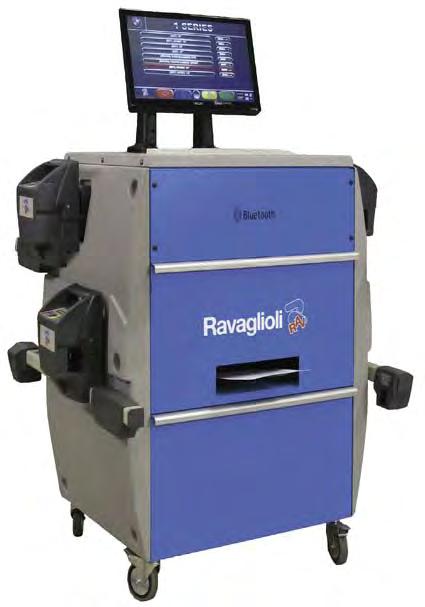

1 Ravaglioli TD1760WS Wheel Alignment System Operational Procedures
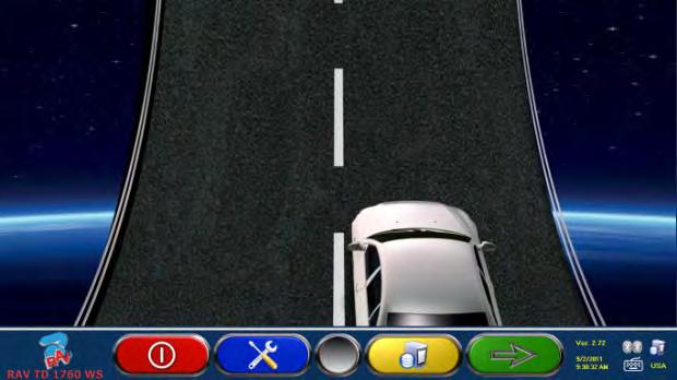
2 SAFELY TURNING ON AND TURNING OFF THE SYSTEM This is the program s main screen. To turn on the program- Set rocker switch on rear of cabinet to the ON position. To turn off the system- Return to the main screen and select the red key. When the message appears on screen It is now safe to turn off your computer turn rocker switch on rear of cabinet to the off position. WARNING: TURNING THE SYSTEM OFF USING ANY OTHER METHOD COULD RESULT IN DAMAGE TO THE COMPUTER. Alignment in Four Colors- Only four color coded keys operate the software. Each sensor head is a fully functional remote control.

3 Vehicle Database Selection Select the green key (F4 on keyboard or at the closest sensor head) and the program advances to the vehicle database selection. USA database is chosen by default so select the green key to advance to the next screen.

4 Vehicle Selection Screen Choose vehicle manufacturer from the column on left by scrolling or by entering the first letters of the manufacturer name. Chosen manufacturer will be highlighted in red box. Select the green key and select the model in the same manner. You may navigate the list by scrolling up and down with the blue and yellow keys.

5 Review of Target Data Selected If the correct vehicle has been selected advance by selecting the green key. If not select the red key to reselect the vehicle. If you are measuring toe in millimeters you may change rim size with the yellow key. Otherwise select the green key to advance to the next step.

6 Adjustment Help Images From the target data review screen any available adjustment images will be identified by the camera icon located on the yellow key. To view these images select the yellow key. Otherwise select the green key to advance.
7 Runout Compensation and Two Head Measurement Mode Note: Runout Compensation Must Be Performed When Using 4 Point Clamps Runout Compensation Skipped If using RAV Non-Runout Fast Clamps select the green key to move forward. Runout Compensation Method- Select the yellow key to choose between raised and rolling runout methods. Front Axle Measurement Using Only Two Sensor Heads- Select the blue key to measure toe and camber on the front axle with only two sensor heads installed.

8 Runout Compensation and Two Head Measurement Mode Note: Runout Compensation Must Be Performed When Using 4 Point Clamps Runout Compensation Skipped If using RAV Non-Runout Fast Clamps select the green key to move forward. Runout Compensation Method- Select the yellow key to choose between raised and rolling runout methods. Front Axle Measurement Using Only Two Sensor Heads- Select the blue key to measure toe and camber on the front axle with only two sensor heads installed. Select green key to move forward in the program. Select red key to move backwards in the program.

9 Runout Compensation in Raised Mode Note: Runout Compensation Must Be Performed When Using 4 Point Wheel Clamps. This is a 2 postion runout procedure If using 4 point wheel clamps you may choose to perform runout compensation in either the raised or the rolling mode. If the raised mode is preferred, raise wheels off runways until they are able to rotate without any interference. Position the wheel at 12 o clock top dead center. From this screen when the center black key is flashing on screen press that button on the actual head key pad. Rotate the wheel to 6 o clock position and press center black key again. When center key on screen stops flashing rotate wheel back to 12 o clock position. Repeat for the other wheels.
10 Runout Compensation in Rolling Mode Note: Runout Compensation Must Be Performed When Using 4 Point Wheel Clamps If you have selected to perform runout compensation in the rolling mode roll the vehicle back until the red arrows on screen align. Press the center black key on any head to confirm. Roll the vehicle forward to its original position and press the black key again to confirm. Rolling runout is complete.
, joust the vehicle suspension, unpin the turning plates, and install the brake pedal")
11 Preparations Before Measurement If you have not done so you should lower the vehicle (if it had been raised), joust the vehicle suspension, unpin the turning plates, and install the brake pedal depressor.


12 Steer Straight Ahead and Level Heads Level the front sensor heads until vials on screen are centered and indicate OK with green check marks. Then steer the front wheels in the direction indicated by the arrow on screen until the centering ball icon is in the green area in the center of the bar graph. The STOP sign appears then hold the position steady.

13 Turning Routine for Caster Measurement Turn wheels to left until ball and carriage icon is in the green area on the slide. Hold position steady until screen changes. Now turn wheel to the right and repeat. When screen changes steer back to the center until the red stop sign appears.

14 Review of Collision Angles Before, during, or after the caster turning routine you may select the yellow key for a review of the vehicle s chassis geometry. These angles can be helpful in diagnosing improper chassis alignment.


15 Diagnosis of Rear Axle Standard View- Details rear axle diagnosis using large bar graphs and vivid red and green colors. Alternate View- Select the blue key for a different view of the rear axle diagnosis. Alternate View- Select the center black key on the sensor head or the F5 key on the keyboard for the printout view of the rear axle diagnosis.

16 Steering Wheel Lock Install the steering wheel locked with the steering wheel spoke in the straight position. If you intend to use the RAV-TOE procedure for setting front toe you should skip this step.

17 Adjustment of the Rear Axle Presence of Wrench Icons Indicate a Live Adjustment Screen Adjust rear angles to preferred targets. Selection of blue key will allow you to view an alternate adjustment screen. Selection of black center key on the sensor head or F5 on the keyboard will allow you to adjust the rear axle while the vehicle is raised.

18 Caster/Camber Adjustment of the Front Axle To unfreeze the caster values- Move the red R to the caster position using the center key on the head or the F5 on the keyboard. Adjustment of caster and camber live- Keep wheels steered to the straight ahead position and DO NOT RELEVEL SENSOR HEADS DURING THE ADJUSTMENT PROCEDURE.
19 Adjustment of Caster/Camber in Raised Mode Select blue key to enter raised mode. Raise vehicle so that wheels are free. Red UP arrows are now visible on each side of screen. Make caster/camber adjustments with straight ahead steering position. Do not re-level sensor heads. After adjustments are completed press blue key before lowering vehicle. Lower and select center black key on sensor head to confirm that vehicle has been lowered.
20 Toe Adjustment on the Front Axle Adjustment of Partial Toes- With steering wheel lock installed and steering wheel in the straight position set left and right toe to the same value and on preferred specification. Adjustment of Total Toe- With center black key on the head or F5 at the keyboard move the red R to the lower toe position. Select shift/f5 at the keyboard to view the Total Toe adjustment values and graph.

21 Using RAV-TOE (Setting Toe with Wheels Steered) Select yellow key to enter RAV-TOE. Adjust toe on left wheel to preferred target. Set steering wheel to straight position and confirm with red key. Select yellow key to adjust toe angle on right. Select blue key to adjust toe on left wheel. Adjust toe on left to preferred target. Select red key to exit.


22 Review and Additional Measurements After adjustment of front toe select green key to move forward to the final printout screen. Final print screen indicates diagnosis, adjustment, and target data values for both axles. Select red key to view additional measurement screen or yellow key to print/store.. When viewing additional measurements use the blue and yellow keys to scroll up or down. Select green to print/store.

23 Printing and Storing the Alignment Report If you choose to print/store the report complete the customer information above. To store the report on the system hard drive select the blue key. To print the report select the yellow key. To return to the main screen ready to begin the next alignment select the green key which in this case is HOME.
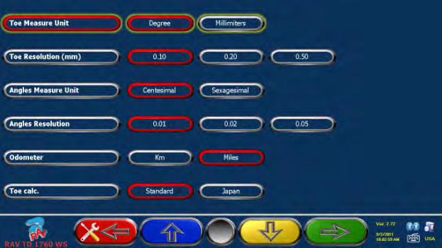
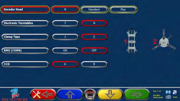
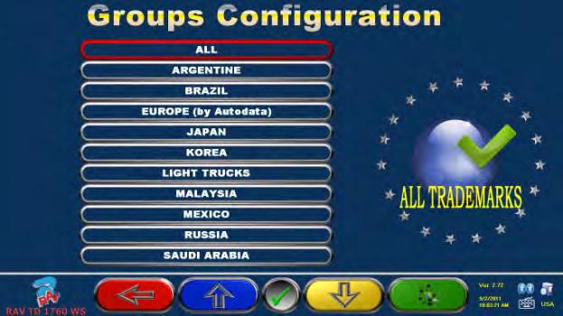
24 Aligner Configuration Settings
Visualiner 3-DTM. Operator's Manual. Form # "FOR REFERENCE ONLY" For Current Information see
 ? Visualiner 3-DTM Operator's Manual Form #5426-2 (BLANK PAGE) ? John Bean Company 309 Exchange Avenue Conway, AR 72032 USA Phone (501) 450-1500 Fax (501) 450-1585 Visualiner 3-DTM Operator's Manual Print
ACCU 2200 CCD COMPUTER WHEEL ALIGNER FOR CARS AND LIGHT TRUCKS WITH CCD SENSORS
 ACCU 2200 CCD COMPUTER WHEEL ALIGNER FOR CARS AND LIGHT TRUCKS WITH CCD SENSORS INSTALLATION AND OPERATION INSTRUCTIONS MAINTENANCE INSTRUCTIONS Page 2 Accu-turn Model 2200 CCD Operator s Manual Accu-turn
Operators Manual EEWA555A and EEWA557A Prism Aligner Systems
 Operators Manual EEWA555A and EEWA557A Prism Aligner Systems Form ZEEWA555A Blank page Safety Safety Information For your safety, read this manual thoroughly before operating the equipment. The Aligner
Advanced Wheel Aligner
 Advanced Wheel Aligner 3000 Series Installation Guide and User Manual Version 09.02 Copyright 2009 KJC Engineering Inc, All rights reserved No part of this publication maybe translated, stored in an electronic
INSTRUCTIONS FOR USE CONTENTS. I /18 - Ver. 00 CAUTION! 3 GENERAL WARNINGS 3 PRECAUTIONS AND INSTRUCTIONS FOR SAFETY, USE AND MAINTENANCE 3
 INSTRUCTIONS FOR USE I CONTENTS CAUTION! 3 GENERAL WARNINGS 3 PRECAUTIONS AND INSTRUCTIONS FOR SAFETY, USE AND MAINTENANCE 3 1 - MACHINE DESCRIPTION 5 1.1 - TECHNICAL DATA 5 2 - PROGRAM FLOW 6 2.1 - HOW
Operators Manual. Imaging Alignment Systems with Pro42
 Operators Manual Imaging Alignment Systems with Pro42 Blank page SAFETY INFORMATION For your safety, read this manual thoroughly before operating the equipment. The Aligner is intended for use by properly
WinAlign Operation Instructions for VAG Aligner
 OPERATION INSTRUCTIONS Form 6611TE-05, 06-13 Supersedes Form 6611TE-05, 01-13 WinAlign Operation Instructions for VAG Aligner Version 14.0 Copyright 2013 Hunter Engineering Company Contents Contents...
1 of 9 7/24/2014 9:02 PM
 1 of 9 7/24/2014 9:02 PM Four-Wheel Alignment Special Service Tools 204-805 CAUTION: Make sure the vehicle is on a flat level surface. CAUTION: Make sure the tire pressures are within specification. CAUTION:
SML Wheel Alignment. Operation & Maintenance Manual. p/n
 SML Wheel Alignment Operation & Maintenance Manual p/n 420-02167-001 CARTEK GROUP All rights reserved. Any reproductions of this document, partial or complete, are only allowed with prior consent of Cartek
GENERAL INFORMATION. Wheel Alignment Theory & Operation
 Fig. 1: Checking Steering Linkage GENERAL INFORMATION Wheel Alignment Theory & Operation ADJUSTMENTS NOTE: This article is intended for general information purposes only. This information may not apply
WinAlign Software Quick Reference Guide
 Form 4307T, 07-05 Supersedes Form 4307T, 09-04 WinAlign Software Quick Reference Guide Version 8.x Copyright 1998-2005 Hunter Engineering Company Contents GETTING STARTED... 1 General Introduction...
User guide. laser AM T
 User guide laser AM T143-1 1210 Table of Contents Getting started [laser AM]...1 Operating the system...1 Starting the software...1 Short steps to perform a measurement...1 Laser AM20-D1...4 Battery...5
WHEEL ALIGNMENT SYSTEM RAV TD 3000 HP 8 LINER 8060 TWSR
 WHEEL ALIGNMENT SYSTEM Wireless RAV TD 3000 HP 8 LINER 8060 TWSR Truck Aligners 24 volt motor with min. power low speed rotation = consumption TOWER-FREE 3D Alignment System EASY ALIGNMENT Monitor 22"
Beissbarth workshop equipment
 2012 Beissbarth workshop equipment For excellent service Innovative equipment technology for professional service Assured product quality Worldwide service guarantee Wheel Alignment Brake Testers Vehicle
CURA S 900 & 960 CCD Wheel alignment
 Homologation CURA S 960 MB CURA S 900 & 960 CCD Wheel alignment Wheel alignment with 8 sensors CCD measuring technology Wheel alignment equipped with precise 8 sensors toe measuring technology, toe for
AUTOMOTIVE GARAGE EQUIPMENT
 AUTOMOTIVE GARAGE EQUIPMENT KWA-300 3D technology wheel aligner for car LAUNCH The 3D Wheel Aligner with 4 digital cameras, targets without on-board electronic and premium PC with Windows XP operation
WHEEL ALIGNMENT SYSTEMS
 WHEEL ALIGNMENT SYSTEMS 1080 BAYSAVER HIGH PERFORMANCE WHEEL ALIGNER EXCLUSIVE 22 Monitor 3D Solid Vision TECHNOLOGY R1080 SPEED Portable aligner console can be positioned anywhere for the ultimate convenience.
Operators Manual - Pro32
 Operators Manual - Pro32 Imaging Alignment Systems Form 5818p1 Blank page Safety Safety Information For your safety, read this manual thoroughly before operating the equipment. The Aligner is intended
ELECTRONIC CHASSIS ALIGNMENT
 SUSPENSION Steering and Wheel Alignment - Repair Instructions - X6 ELECTRONIC CHASSIS ALIGNMENT 32... OVERVIEW OF STEERING Fig. 1: Overview Of Steering 32... OVERVIEW OF ACTIVE FRONT STEERING Fig. 2: Overview
Accu-Turn. A turn for the better
 Accu-Turn A turn for the better Operators Manual Computerized Wheel Aligner IMPORTANT SAFETY INSTRUCTIONS For your safety, read this manual thoroughly before operating the Equipment The Aligner is intended
CWA21. Giuliano Industrial S.p.A.
 Wheel Alignment for passenger's cars and LCVS, 3D Camera Imaging Wheel Alignment for passenger's cars and LCVS, 3D Camera Imaging. Designed for high-volume shops, provides high quality measurements in
Basic Wheel Alignment Techniques
 Basic Wheel Alignment Techniques MASTERING THE BASICS: Modern steering and suspension systems are great examples of solid geometry at work. Wheel alignment integrates all the factors of steering and suspension
Bosch: Skilled partner for workshop business
 WAW 4155 EN 04.2009 The right to make changes of a technical nature and to alter the range on offer is reserved Bosch: Skilled partner for workshop business Developments from Bosch stand for innovative
WHEEL ALIGNMENT SPECIFICATIONS & PROCEDURES
 WHEEL ALIGNMENT SPECIFICATIONS & PROCEDURES 1988 Jeep Cherokee 1988 Wheel Alignment INTRODUCTION PRE-ALIGNMENT VEHICLE CHECKS Prior to making wheel alignment adjustments, check and adjust the following
Trademark Information. General Notice. Copyright Information
 LAUNCH KWA-521 Wheel Aligner Trademark Information LAUNCH is a registered trademark of LAUNCH TECH. CO., LTD. (short for LAUNCH) in China and other countries. All other LAUNCH trademarks, service marks,
UNIMECK. Presents Truck Wheel Equipments. We Are The Leading Manufactures. Of Garage Equipments...
 UNIMECK TM Tyre Service Equipment Pvt. Ltd. We Are The Leading Manufactures Of Garage Equipments... Presents Truck Wheel Equipments www.unimeckauto.com Heavy Vehicles/Truck & Bus Wheel Balancer Features:
WinAlign Alignment Software
 QUICK REFERENCE GUIDE Form 4307TE-05, 07-09 WinAlign Alignment Software Version 11.x Copyright 2007-2009 Hunter Engineering Company CONTENTS 1. GETTING STARTED... 3 1.1 General Introduction... 3 References...
Camber Angle. Wheel Alignment. Camber Split. Caster Angle. Caster and Ride Height. Toe Angle. AUMT Wheel Alignment
 AUMT 1316 - Wheel Alignment 11/15/11 Camber Angle Wheel Alignment Donald Jones Brookhaven College Camber Split Camber is the amount that the centerline of the wheel tilts away from true vertical when viewed
WAB 02 CCT. non contact, fully automatic, highest precision. Made in Germany
 WAB 02 CCT non contact, fully automatic, highest precision Made in Germany WAB 02 CCT Wheel alignment has never been so quick, precise and simple! Colour coded optical CCT measuring technology revolutionises
ProAlign Alignment Systems NEW!
 ProAlign Alignment Systems NEW! Alignment measurements in just minutes! Pronto digital imaging technology offers shops alignment service optimized for speed and efficiency with simple operation and low
Operators Manual. Imaging Alignment Systems. Form ZEEWA137A
 Operators Manual Imaging Alignment Systems Form ZEEWA137A Blank page Safety Safety Information For your safety, read this manual thoroughly before operating the equipment. The Aligner is intended for use
MERCEDES-BENZ WHEEL ALIGNMENT
 MERCEDES-BENZ WHEEL ALIGNMENT CAMERA TECHNOLOGY FOR YOUR WORKSHOP Powered by Photo credit: Daimler AG INVEST IN MODERN TECHNOLOGY TO GROW YOUR BUSINESS Homologated by Mercedes Benz for trucks, buses and
V (For X-712/X-712 Short Column/X-712 Wall-mounted/X-712HD)
") V2.01.000 2012-09-10 (For X-712/X-712 Short Column/X-712 Wall-mounted/X-712HD) LAUNCH X-712 Wheel Aligner Trademark Information LAUNCH is a registered trademark of LAUNCH TECH. CO., LTD. (LAUNCH for short)
V2.01.000 2012-09-10 (For X-712/X-712 Short Column/X-712 Wall-mounted/X-712HD) LAUNCH X-712 Wheel Aligner Trademark Information LAUNCH is a registered trademark of LAUNCH TECH. CO., LTD. (LAUNCH for short)
Wheel Alignment For Trucks
 Wheel Alignment For Trucks Operating Manual ENG Rev. 04 July 2006 (sw aligner_t 2.5.x ) Contents 1 GENERAL INFORMATION...5 1.1 SUSPENSIONS...5 1.2 GEOMETRICAL ATTITUDE OF THE MOTOR VEHICLE...5 1.3 TYPICAL
V
 V1.01.000 2018-07-07 LAUNCH X-861 Wheel Aligner User s Manual Trademark Information LAUNCH is a registered trademark of LAUNCH TECH. CO., LTD. (LAUNCH) in China and other countries. All other LAUNCH trademarks,
WHEEL ALIGNMENT PROCEDURES
 Page 1 of 8 WHEEL ALIGNMENT PROCEDURES TURNING ANGLE Turn steering wheel fully right and then left, and observe turning radius on both wheels. If turning radius is incorrect, inspect and replace any damaged
ALIGNMENT AND ROAD CROWN
 Classification: Reference: Date: ST08-001 NTB08-097 October 9, 2008 ALIGNMENT AND ROAD CROWN APPLIED VEHICLES: All Nissan - except GT-R SERVICE INFORMATION Customers may report that their vehicle pulls
Flexible and precise: tablet operated wheel alignment
 Flexible and precise: tablet operated wheel alignment FWA 4650 highly precise, fast and flexible: 12 Camera 3D wheel alignment operated by tablet Flexible operation with a workshop-owned tablet or notebook
Wheel Alignment And Diagnostic Angles (STE04)
") Module 1 Wheel Alignments Wheel Alignment And Diagnostic Angles (STE04) Wheel Alignments o Conditions Requiring An Alignment o Conditions Requiring An Alignment (cont d) o Why We Do Checks And Alignments
Module 1 Wheel Alignments Wheel Alignment And Diagnostic Angles (STE04) Wheel Alignments o Conditions Requiring An Alignment o Conditions Requiring An Alignment (cont d) o Why We Do Checks And Alignments
V
 V1.00.000 2011-08-09 LAUNCH X-712 Wheel Aligner Trademark Information LAUNCH is a registered trademark of LAUNCH TECH. CO., LTD. (LAUNCH for short) in China and other countries. All other LAUNCH trademarks,
V
 V1.01.000 2018-05-08 LAUNCH X-931 Touchless Wheel Aligner User s Manual Trademark Information LAUNCH is a registered trademark of LAUNCH TECH. CO., LTD. (LAUNCH) in China and other countries. All other
- Wheel Aligner 3D SERIES
 Procedure for the positioning of the ADAS MaxiSys ADAS system calibration panel on the with 3D wheel aligner 1. Introduction The positioning of the calibration kit of the MaxiSys ADAS (Advanced Driver
geolinertm 680/670 WHEEL ALIGNERS
 geolinertm 680/670 WHEEL ALIGNERS EZ-LINK* STEERING ANGLE SENSOR (SAS) RESET EZ-Link* software alerts the technician of OEM service & maintenance procedures related to Electronic Stability Control and
WHEEL SERVICE EQUIPMENT WHEEL ALIGNMENT SYSTEMS NOTHING ELSE IS A
 WHEEL SERVICE EQUIPMENT WHEEL ALIGNMENT SYSTEMS WHEELALIGNERS NOTHING ELSE IS A MERIDIAN ALIGN COLLISION MEASURING and WHEEL ALIGNMENT The total Live Mapping TM and 3D Alignment System in a portable workstation
WA Sensor CCD wheel aligner. Bernhard Hoffmann Director Product Management. 12. December Die NUSSBAUM Gruppe
 WA 780-8 Sensor CCD wheel aligner Bernhard Hoffmann Director Product Management 12. December 2014 1 Die NUSSBAUM Gruppe Key wheel alignment angles Toe / total toe The angle between midplaneof tire and
Trip 2, 2L, 3 and 5W Owner s Manual. ENGLISH
 Trip 2, 2L, 3 and 5W Owner s Manual. ENGLISH WELCOME. Thank you for buying a Bontrager Trip computer. We hope this computer gives you miles (or kilometers) of pleasure. Your Trip computer may not include
F-150 CARD/STICKERS/POCKET (SLEEVE)
") CARD/STICKERS/POCKET (SLEEVE) IMPORTANT: THE PRO TRAILER BACKUP ASSIST DEPENDS ON HOW AND WHERE YOU PLACE THE STICKER. DO NOT ATTEMPT TO PLACE THE STICKER UNTIL YOU READ THROUGH ALL OF STEP 3 ON PAGES
CARD/STICKERS/POCKET (SLEEVE) IMPORTANT: THE PRO TRAILER BACKUP ASSIST DEPENDS ON HOW AND WHERE YOU PLACE THE STICKER. DO NOT ATTEMPT TO PLACE THE STICKER UNTIL YOU READ THROUGH ALL OF STEP 3 ON PAGES
Operators Manual - Pro32. Imaging Alignment Systems
 Operators Manual - Pro32 Imaging Alignment Systems Blank page Safety Safety Information For your safety, read this manual thoroughly before operating the equipment. The Aligner is intended for use by properly
FRONT SUSPENSION SECTION FSU CONTENTS SUSPENSION FSU-1 SYMPTOM DIAGNOSIS... 2 PRECAUTION... 3 REMOVAL AND INSTALLATION...13 PREPARATION...
 SUSPENSION SECTION FSU A FRONT SUSPENSION B C D CONTENTS FSU SYMPTOM DIAGNOSIS... 2 NOISE, VIBRATION AND HARSHNESS (NVH) TROUBLESHOOTING... 2 NVH Troubleshooting Chart...2 PRECAUTION... 3 PRECAUTIONS...
Powered by SCANIA WHEEL ALIGNMENT
 Powered by SCANIA WHEEL ALIGNMENT Bad wheel alignment will ruin your customer s economy! A properly aligned vehicle can reduce fuel consumption costs by up to 5%. Bad wheel alignment also increases tire
2004 SUSPENSION. Wheel Alignment - Corvette. Caster Cross +/ / Fastener Tightening Specifications Specification Application
 2004 SUSPENSION Wheel Alignment - Corvette SPECIFICATIONS WHEEL ALIGNMENT SPECIFICATIONS Wheel Alignment Specifications Camber Cross Caster Cross Suspension Camber Tolerance Caster Tolerance FE1 & FE3
Card/Stickers/Pocket (Sleeve) 2016 F-150 Pro Trailer Backup Assist QUICK START GUIDE
 2016 F-150 Pro Trailer Backup Assist QUICK START GUIDE") Card/Stickers/Pocket (Sleeve) IMPORTANT: The Pro Trailer Backup Assist depends on how and where you place the sticker. DO NOT ATTEMPT TO PLACE THE STICKER UNTIL YOU READ THROUGH ALL OF STEP 3 ON PAGES
Card/Stickers/Pocket (Sleeve) IMPORTANT: The Pro Trailer Backup Assist depends on how and where you place the sticker. DO NOT ATTEMPT TO PLACE THE STICKER UNTIL YOU READ THROUGH ALL OF STEP 3 ON PAGES
geoliner 780 WHeel aligner
 geoliner 780 WHEEL ALIGNER Maximize Profits with the geoliner TM 780 The geoliner TM 780 is the fastest, most accurate aligner in the industry. Thanks to its DigiSmart technology, the geoliner TM 780 s
All about the wheel: Bosch wheel alignment
 All about the wheel: Bosch wheel alignment The wheel alignment series provides the best fit in terms of wheel alignment equipment for any workshop. Whether it's devices with CCD, 3D or non-contact technology
Wheel Alignment VISUALINER 3D ARAGO SC
 Wheel Alignment VISUALINER 3D ARAGO SC Worlds First Self Calibrating Alignment System REVOLUTIONARY LIFT SYNCHRONIZATION THE NEW V3D ARAGO SC TM The V3D ARAGO advances Error-Free alignment technology with
1993 Jeep Grand Cherokee. WHEEL ALIGNMENT SPECIFICATIONS & PROCEDURES 1993 WHEEL ALIGNMENT Chrysler Corp. - Specifications & Procedures
 ADJUSTMENTS CAMBER MEASUREMENT Check camber to determine if any components are bent or damaged. Camber angle is NOT adjustable. If angle is not to specification, components causing problem must be replaced.
Computerscales DX Model Operating Instructions (Also applies to models 72632, 72635, 72636)
") 16892 146 th St SE, Monroe, WA 98272 (360) 453-2030 Computerscales DX Model 72634 Operating Instructions (Also applies to models 72632, 72635, 72636) QUICK START INSTRUCTIONS: 1) Set up pads alongside
16892 146 th St SE, Monroe, WA 98272 (360) 453-2030 Computerscales DX Model 72634 Operating Instructions (Also applies to models 72632, 72635, 72636) QUICK START INSTRUCTIONS: 1) Set up pads alongside
VEHICLE RONT END ALIGNMENT SYSTEM SPECIFICATIONS OR EQUIVLANT TERMS AND CONDITIONS YES NO DEVIATIONS
 VEHICLE RONT END ALIGNMENT SYSTEM SPECIFICATIONS OR EQUIVLANT TERMS AND CONDITIONS YES NO DEVIATIONS 1) New, Current Year Model. 2) Deliver and install within 90 days. 3) Delivery One (1) Complete Set,
Fiat - Argentina - Wheel Aligner / Headlamp Aimer #16435
 2017 Fiat - Argentina - Wheel Aligner / Headlamp Aimer #16435 Wheel Aligner / Headlamp Aimer Operation & Maintenance Manual Overview Fori Automation Version 1.2 4/21/2017 TABLE OF CONTENTS Section 1.0
UNITED STATES Ford Customer Relationship Center (FORD) (TDD for the hearing impaired: ) owner.ford.
 (TDD for the hearing impaired: ) owner.ford.") CARD/STICKERS/POCKET (SLEEVE) IMPORTANT: Pro Trailer Backup Assist depends on how and where you place the sticker. Do not attempt to place the sticker until you read through all of Step 3 on pages 9 and
CARD/STICKERS/POCKET (SLEEVE) IMPORTANT: Pro Trailer Backup Assist depends on how and where you place the sticker. Do not attempt to place the sticker until you read through all of Step 3 on pages 9 and
Table of Content. Precautions Definition Functions and Features Requirements on Surroundings - 4 -
 Precautions 1. Please read the User s Manual carefully before operating the Wheel Aligner. 2. Only the qualified technician can operate the Wheel Aligner. 3. The operator must have knowledge of computer
Wheel alignment by Bosch: CCD, 3D or non-contact
 Wheel alignment by Bosch: CCD, 3D or non-contact Recognise revenue opportunities in wheel alignment Workshop tests carried out by Bosch have shown that the running gear of up to 75 % of tested vehicles
General Notice. Trademark Information. Copyright Information
 LAUNCH Trademark Information LAUNCH is a registered trademark of LAUNCH TECH. CO., LTD. (short for LAUNCH) in China and other countries. All other LAUNCH trademarks, service marks, domain names, logos,
Operating Instructions Operating Instructions. HEKA testing lane UNIVERS "TX" 4cm above floor
 1 Operating Instructions Operating Instructions Brakes, suspension and toe Manufacturer: HEKA AUTO TEST GMBH Ensisheimer Str. 4 79110 Freiburg / Germany Tel.: +49-761-81080 E-Mail: info@heka-online. For
REAR SUSPENSION SECTION RSU CONTENTS E SUSPENSION RSU-1 RSU
 E SUSPENSION SECTION RSU A REAR SUSPENSION B C D CONTENTS RSU PRECAUTIONS... 2 Precautions for Supplemental Restraint System (SRS) AIR BAG and SEAT BELT PRE-TEN- SIONER... 2 Precautions for Rear Suspension...
Computerscales DX Model Operating Instructions
 16892 146 th St SE, Monroe, WA 98272 (360) 453-2030 Computerscales DX Model 72641 Operating Instructions QUICK START INSTRUCTIONS: 1) Set up pads alongside kart (they are interchangeable). 2) Connect cables
ProAlign Alignment Systems Optimized for speed and efficiency
 ProAlign Alignment Systems Optimized for speed and efficiency Alignment measurements in just minutes! Pronto alignment systems using HawkEye digital imaging technology offers shops alignment service optimized
Visualiner 3D 1, 3D 2 X-Cel Series
 Visualiner 3D 1, 3D 2 A generation ahead To continue to maintain their leadership in imaging aligners, John Bean presents its new generation of 3D aligners, the Visualiner 3D X-Cel series. The new ultra
Wheel alignment equipment. Lithium batteries, BT 2 communication. NEW PRODUCT. DWA 1000 Light
 Wheel alignment equipment. Lithium batteries, BT 2 communication. NEW PRODUCT B A L A N C I N G M A C H I N E S DWA 1000 Light DWA 1000 LIGHT general features 8 CCD sensors equipment for the alignment
geoliner 680 and geoliner 780
 geoliner 680 and geoliner 780 3D wheel alignment 3D wheel alignment Accurate The high-definition cameras have a wide viewing angle. All vehicle specs are supplied directly from the OEMs and are, therefore,
JHM Butt & Co Ltd. Station Yard, Bawtry, Doncaster, South Yorks DN10 6QD Tel:
 JHM Butt & Co Ltd Station Yard, Bawtry, Doncaster, South Yorks DN10 6QD Tel: 01302 710868 Email: info@buttsofbawtry.com www.buttsofbawtry.com Our Tracking Guage Single Steer Rear Flag - Car Turn Table
Four-Wheel Alignment ( )
") Published: Mar 7, 2005 Four-Wheel Alignment (57.65.04) CAUTION: Make sure the vehicle is on a flat level surface. CAUTION: Make sure the tire pressures are within specification. CAUTION: Make sure that
Published: Mar 7, 2005 Four-Wheel Alignment (57.65.04) CAUTION: Make sure the vehicle is on a flat level surface. CAUTION: Make sure the tire pressures are within specification. CAUTION: Make sure that
ONE YEAR LIMITED WARRANTY
 TABLE OF CONTENTS ONE YEAR LIMITED WARRANTY Warranty 1 Overview Drawing 3 Parts List 4 Hardware List 7 Assembly Instructions 9 How to Fold-Up the Extrusion 14 How to Fold-Down the Extrusion 15 Adjustment
CARWAY INSTRUCTION MANUAL
 CARWAY INSTRUCTION MANUAL 1 Content I. Product Features and technical specifications... 2 1.1 Measurement Principle of 3D Digital Imaging Wheel Alignment... 2 1.2 Features of X3D wheel alignment... 2 1.3
K&L MC200 ELITE WHEEL BALANCER Product Manual - MC Wheel Balancing
 Product Manual - MC Wheel Balancing Thank you for purchasing this K&L Product. Please inspect this unit for damage prior to use. This manual will review balancing a motorcycle wheel. Please read the entire
TWIN BUSCH GmbH. Printing errors, mistakes and technical changes reserved by TwinBusch Germany 2
 TWIN BUSCH GmbH Printing errors, mistakes and technical changes reserved by TwinBusch Germany 2 TWIN BUSCH GmbH INDEX 1. Important note 5 1.1 Important note 1.2 Specialist 1.3 safety instructions 2. Overview
SUSPENSION 2-1 SUSPENSION TABLE OF CONTENTS
 XJ SUSPENSION 2-1 SUSPENSION TABLE OF CONTENTS page ALIGNMENT... 1 FRONT SUSPENSION... 7 page REAR SUSPENSION... 16 ALIGNMENT TABLE OF CONTENTS page AND WHEEL ALIGNMENT...1 DIAGNOSIS AND TESTING SUSPENSION
Wheel Alignment - Basics
 Service Training Self Study Program 860103 Wheel Alignment - Basics Volkswagen Group of America, Inc. Volkswagen Academy Printed in U.S.A. Printed 2/2012 Course Number 860103 2012 Volkswagen Group of America,
REAR SUSPENSION SECTION RSU CONTENTS SUSPENSION RSU-1 REMOVAL AND INSTALLATION...10 SYMPTOM DIAGNOSIS... 2 PRECAUTION... 3 PREPARATION...
 SUSPENSION SECTION RSU A REAR SUSPENSION B C D CONTENTS RSU SYMPTOM DIAGNOSIS... 2 NOISE, VIBRATION AND HARSHNESS (NVH) TROUBLESHOOTING... 2 NVH Troubleshooting Chart...2 PRECAUTION... 3 PRECAUTIONS...
BAER Your Complete Performance Brake Supplier!
 Installation Instructions Product: SS4 / SS4+ / Pro+ / Ext+ Rear w/ park brake Instruction Part Number: 6000264 Revision Date: 27 August 27, 2014 Vehicle Make: Model Year(s): General Fit 8 & 9 Ford Rear
Hofmann Megaplan USA. 3D Wheel Aligner megaline SSENCE 500. Users Manual for software version 1.0.0
 Hofmann Megaplan USA 3D Wheel Aligner megaline SSENCE 500 Users Manual for software version 1.0.0 Hofmann Megaplan GmbH Hauptstraße 67 5302 Henndorf am Wallersee Austria Tel: +43 6214-64 66 12 Fax: +43
Conversion to AMG sports suspension Model 129 without level control on rear axle
 Installation instructions Conversion to AMG sports suspension Model 129 without level control 32.10 on rear axle Models 129.058/060/061/063/066/067 - USA versions are excluded. These installation instructions
Fiat - Argentina - Wheel Aligner / Headlamp Aimer #16435
 2017 iat - Argentina - Wheel Aligner / Headlamp Aimer #16435 Wheel Aligner / Headlamp Aimer Operation & Maintenance Manual Calibration / Testing ori Automation Version 1.2 4/21/2017 iat - Argentina - Wheel
Alignment Accessories
 Alignment Accessories CodeLink The New Last Step in Alignment Service CodeLink directly links the vehicle OBD-II to the aligner to reset steering system sensors, as required by the manufacturer. 20-2150-1
Alignment Accessories
 Alignment Accessories Measurement & Adjustment Remote Indicators Hunter Remote Indicators Speed Alignment Service Hunter Remote Indicators are designed to provide the operator with complete control while
Y62 PATROL 17 DIGIT VIN LOCATIONS. Only use CONSULT-III plus. Do NOT under any circumstance ever try to use CONSULT II. January 2013.
 Y62 PATROL 17 DIGIT VIN LOCATIONS January 2013 Tyre Pressure Placard Australian Compliance Decal at B pillar Factory ID Plate VIN stamped to Chassis rail Only use CONSULT-III plus. Do NOT under any circumstance
Hemet High School NATEF SUSPENSION AND STEERING CHECKLIST. Name Date Period
 Hemet High School NATEF SUSPENSION AND STEERING CHECKLIST Name Period For every task in Suspension and Steering, the following safety requirement must be strictly enforced: Comply with personal and environmental
TripTek Tire Car Kit Installation Procedure
 TripTek Tire Car Kit Installation Procedure ANTENNA INSTALLATION 1. Assemble the antenna. Be sure to install the rubber washer and tighten the assembly using a wrench. 2. Magnetically mount the antenna
Alignment Accessories
 Alignment Accessories CodeLink The New Last Step in Alignment Service CodeLink directly links the vehicle OBD-II to the aligner to reset steering system sensors, as required by the manufacturer. 20-2150-1
REAR SUSPENSION SECTION RSU CONTENTS SUSPENSION RSU-1 REMOVAL AND INSTALLATION...10 SYMPTOM DIAGNOSIS... 2 PRECAUTION... 3 PREPARATION...
 SUSPENSION SECTION RSU A REAR SUSPENSION B C D CONTENTS RSU SYMPTOM DIAGNOSIS... 2 NOISE, VIBRATION AND HARSHNESS (NVH) TROUBLESHOOTING... 2 NVH Troubleshooting Chart...2 PRECAUTION... 3 PRECAUTIONS...
 VOLUME 2.0 2 This page intentionally left blank JWB 100 Operator s Manual page 3 Table of Contents 1 Summary 1.1 Features 4 1.2 Specifications 4 2 Installation 2.1 Installation 5 3 Structure 3.1 Main Structure
Geofix 10.0 Light Wheel alignment equipment. Lithium batteries, BT 2 communication
 Geofix 10.0 Light Wheel alignment equipment. Lithium batteries, BT 2 communication Geofix 10.0 Light general features 8 CCD sensors equipment for the alignment of car and light commercial vehicle wheels
The best thing to happen to Wheel Alignment since... The Wheel.
 The best thing to happen to Wheel Alignment since... The Wheel www.quicktrak.co We d like you to know... QuickTrak Wheel Aligners are hand-made in Sheffield, England. The quality is there for all to see,
SUSPENSION 2-1 SUSPENSION CONTENTS
 WJ SUSPENSION 2-1 SUSPENSION CONTENTS page ALIGNMENT... 1 FRONT SUSPENSION... 4 page REAR SUSPENSION... 15 ALIGNMENT INDEX page AND WHEEL ALIGNMENT... 1 SERVICE PROCEDURES PRE-ALIGNMENT... 2 AND WHEEL
STEERING SYSTEM Introduction
 STEERING SYSTEM Introduction The steering makes it possible to change direction. The steering must be reliable and safe; there must not be too much play in the steering. It must be possible to steer accurately.
II YEAR AUTOMOBILE ENGINEERING AT AUTOMOTIVE CHASSIS QUESTION BANK UNIT I - LAYOUT, FRAME, FRONT AXLE AND STEERING SYSTEM
 II YEAR AUTOMOBILE ENGINEERING AT 6402 - AUTOMOTIVE CHASSIS QUESTION BANK UNIT I - LAYOUT, FRAME, FRONT AXLE AND STEERING SYSTEM 1. Write about the requirements of frame and selection of cross section
AER Automotive Steering and Suspension
 2013 NATEF JOB TASKS COMPLETION REQUIREMENT: P1-95% P2-80% P3-50% Student Name: DETAILED COURSE CONTENT AUTOMOTIVE SUSPENSION AND STEERING TECHNICIAN DEMONSTRATE PROFICIENCY IN SUSPENSION AND STEERING
INDEX GENERAL. Page Connecting Rod 2M-3 Front Wheel Alignment 2M-4 Front Wheel Shimmy 2M-5 General 2M-1
 INDEX Page Connecting Rod 2M-3 Front Wheel Alignment 2M-4 Front Wheel Shimmy 2M-5 General 2M-1 Pago Specifications 21-8 Steering Damper 2M-3 Steering Wheel Spoke Alignment 2M-5 Tie Rod 2M-3 GENERAL The
Inclinometer for Electronic Wheel Alignment Machines
 Inclinometer for Electronic Wheel Alignment Machines Part-Number 913 009 024 Manual GEB 001 017 HAWEKA AG Kokenhorststraße 4 30938 Burgwedel 05139/8996-0 05139/8996-222 Table of Contents 1. IMPORTANT!...
geoliner 670, 680 and 780
 geoliner 670, 680 and 780 3D wheel alignment 3D wheel alignment Accurate The high-definition cameras have a wide viewing angle. All vehicle specs are supplied directly from the OEMs and are, therefore,