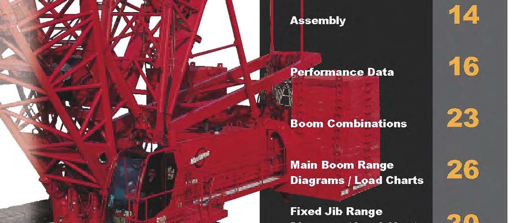
Index Performance Data Working Weights Assembly Manitowoc Crane CARE SM
|
|
|
- Amanda Daniels
- 5 years ago
- Views:
Transcription


1
2 Index Specifications Outline Dimensions and Weights Wire Rope engths Wire Rope Specifications Combinations Range Diagram and Capacity Charts No. 00 Basic Crane Engine(s) Controls ydraulic System Drums & aggings oist Swing System Support System Counterweights Operator s Cab Carbody, Rotating Module Crawlers Optional Self-erect System ook block/weight ball Miscellaneous Optional Equipment Performance Data Working Weights Assembly Manitowoc Crane CARE SM No. 55 or 55A No. 55 or 55A with eavy-ift Top No. 55 or 55A with eavy-ift Top with No. 79A Fixed Jib No. 55 or 55A with eavy-ift Top with No. 79A uffing Jib No A No A with eavy-ift Top No A with eavy-ift Top with No. A uffing Jib MAX-ER TM 000 MAX-ER TM 000 No. 55 or 55A with eavy-ift Top No. 55 or 55A with eavy-ift Top with No. 79A Fixed Jib No. 55 or 55A with eavy-ift Top with No. 79A uffing Jib
3 specifications Upperworks Engine Cummins Model QSX 5 Diesel, cylinder, 7 kw (00 0 high-idle RPM. Includes engine block heater (V), ether starting aid, transmission disconnect clutch for cold weather starting, high silencing muffler, hydraulic oil cooler, radiator and fan. Multiple hydraulic pump drive transmission provides independent power for all machine functions. Two volt maintenance-free batteries, 300 CCA at - C (0 F), volt system and 75 amp alternator. One diesel fuel tank, 00 l (75 gal.), mounted on rear of upperworks, with level indicator in operator s cab. Optional: Cold-weather package with heater for fluids, brake pedals, batteries and computer display. Controls and internal diffuser. Each function is equipped with relief valves to protect the hydraulic circuit from overload or shock. System includes oil cooler and replaceable, tenmicron absolute full flow filter. All oil is filtered before entering the hydraulic pumps. ydraulic system also includes pump transmission disconnect and hydraulic oil cooler. System kg/cm (psi) lpm (gpm) Main oisting Drum (,000) 77 (00) Main oisting Drum (,000) 77 (00) Whip Drum (,000) 37 (0) oist (,000) 05 () Standard Dual Swing Optional Quad Swing (,000) 30 (0) (,000) 05 () eft Crawler (,000) 37 (0) Right Crawler (,000) 37 (0) Mast oist (,000) 37 (0) 3 Modulating electronic-over-hydraulic controls provide infinite speed response directly proportional to control lever movement. Controls include Manitowoc s exclusive EPIC (Electronically Processed Independent Control) system with CAN-BUS technology providing microprocessor driven control logic, pump control, on-board diagnostics, and service information. Block-up limit control is standard for hoist and whip lines. Integrated wireless oad Moment Indicator system (MI) offers standard load link for main boom and upper boom point. Function cut-out or warning only operation is selected via the Operator Interface Display on the MI console. Travel and swing alarms are standard. Optional: Anemometer (wind speed indicator). s and jibs are prewired for anemometer. ydraulic System Multiple high-pressure piston pumps, driven by a multi-pump transmission, provide independent closed-loop hydraulic power for the hoisting drums, boom hoist, swing, left crawler and right crawler. ydraulic reservoir has a capacity of l (3 gal.) and is equipped with a breather, clean out access, Optional uffing oist (,000) 05 () Drums Basic machine is equipped with one (No. 55/79A ) or two (No. 55 or No. 55A ), cm (9-/") wide,,5 cm (5-3/") diameter hoist drums, one in the 3,0 m (') boom insert and one in the boom butt. Each end of each drum is driven by a variable-displacement hydraulic motor through a planetary reduction. Each drum drive is equipped with a bi-directional drum brake. Whip drum is, cm (3-3/") wide and, cm (5-/") diameter, grooved for mm wire rope and driven by a variable-displacement hydraulic motor through a planetary reduction. Drum rotation indicator for each drum is standard. Bolt-on (shell-type), cm (9-/") laggings for mm or 3 mm dia. wire rope for liftcrane applications. Swing System igh strength fabricated steel alloy rotating bed is mounted on 3,0 m (9' ") diameter triple-row roller bearing turntable. Rotating bed s upper and lower modules are fabricated steel and connected by four power actuated pins. ydraulic connection of upper and lower modules is made through quick-coupled
4 specifications hydraulic lines. Enclosures are included on both sides of the upper module. Independent swing powered by fixed displacement hydraulic motors coupled to planetary reduction gearboxes with internal brakes. 30 positive swing lock. Swing system maximum speed:. rpm. Mast oist System Single drum mast hoist mounted in rotating bed is powered by a fixed displacement hydraulic motor and a planetary reduction gear box with internal brake. Ratcheting pawl is standard. Includes mast-hoist wire rope. oist System Independent boom hoist, mounted in the mast butt has grooved drum mm ()") wide and 355 mm (53-3/") diameter. Each end of drum is powered by a variabledisplacement hydraulic motor coupled to a planetary reduction gearbox with internal brake. Ratcheting pawl. rotation indicator, pressure roller and wire rope for -part boom hoist line are standard. hoist speed: raise,9 m (00') No. 55/79A main boom from 0 - in minutes, seconds. Raise 97,5 m (30') No. 55 main boom from 0 - in minutes, seconds. Counterweight UNIT WEIGT TOTA WEIGT QTY. ITEM kg lb kg lb Carbody ower Box 9 95, ,000 Tray 700, ,000 Carbody Total ,000 Upperworks Upper Box 5, ,000 Tray 5 3,000,,000 Upperworks Total ,000 Counterweight TOTA 3 7,000 Includes connecting pins, brackets, and stops. Vision Operator s Cab The Vision Cab is a fully enclosed and insulated steel module mounted to the left front corner of rotating bed. Module is equipped with power tilt, sliding door, large safety glass windows on all sides and roof. Signal horn, power seat, all season climate control package, front and roof windshield wipers, dome light, sun visor and shade, fire extinguisher, swing and travel alarms, and radio/cd player are standard equipment. Operator s station swings over front of rotating bed for transportation. owerworks Carbody Moving Mast Support System Moving mast is 9,m (30') long and connects to the fixed mast suspension rigging. When used with the optional self-erect package, the mast is utilized for crane assembly and disassembly. It is capable of lifting and positioning the crawler assemblies. Fixed Mast Stationary No. 5 lattice mast provides geometry to raise and support all boom lengths. 30,5 m (0') mast standard for basic crane;,7 m (') mast required for MAX-ER applications. -hoist rope reeved from drum in mast butt through sheaves in mast top and boom-hoist equalizer forms -part boom-hoist rigging. igh-strength steel straps connect equalizer to boom top. Cushioned boom stop and automatic boom stop are standard. Connects rotating bed and crawler frames. Fabricated steel rotating bed lower module mounts to singlepiece carbody by a 3 m (9' ") diameter triple-row roller bearing turntable. Each crawler frame is mounted to the carbody with FACT connection system power-actuated pins. Crawler drive motors are mounted on carbody, permitting crawler removal without opening travel drive hydraulic circuit. Crawlers Crawler assemblies are, m (3' 9") long with,5 m (5') wide cast steel crawler pads low maintenance intermediate rollers. Each crawler is powered independently by two variable displacement hydraulic motors and includes two hydraulically powered pin actuators for fast installation and removal from carbody. Carbody mounted drive motors are connected to crawler final reduction via drive shafts. Crawlers provide ample tractive effort allowing counter-rotation with full rated load. Maximum ground speed is, kph (0.7 mph).
5 specifications Attachments No A The liftcrane is equipped with a 3, m (') No. 55/79A tubular-chord boom consisting of a, m (0') No. 55 or No. 55A butt, 3,0 m (') No. 55 or No. 55A insert,, m (0') No. 55 or No. 55A insert,, m (0') No. 55/79 transition insert with equalizer platform, and 9, m (30') No. 79A heavy-lift top with sixteen 7 mm (30") diameter roller bearing sheaves on one shaft. Includes rope guides, boom angle indicator, and a 7, t (30 USt) swivel hook and weight ball weighing 70 kgs (,00 lbs) for mm or 3 mm wire rope. The No. 55/79A boom utilizes steel suspension straps and Manitowoc s patented, exclusive FACT connection system. Powered boom hinge system including cylinder, piping, operating controls, and locking device are standard. uffing jib preparation is standard. Optional:, m (0'), and, m (0') No. 79 boom inserts with steel boom suspension straps, and FACT connection system. Optional:, m (0') No. 55 or No. 55A boom insert with steel boom suspension straps, and FACT connection system. Optional:, m (0') No. 55 or No. 55A boom insert with luffing drum sheaves, steel boom suspension straps, and FACT connection system. Optional: Intermediate suspension, required for boom lengths of 9,7 m (30') or more. Optional: Detachable upper boom point with one 7 mm (30") diameter tapered roller bearing steel sheave with rope guard, for liftcrane use on heavy-lift boom top. (Same upper point used on Models 555, 777, 777T,, M-50, and 50.) Utilize optional boom inserts in combination with the No. 55/79A basic boom for total lengths up to,9 m (00'). No. 55 or No. 55A The liftcrane is equipped with a 3, m (') No. 55 or No. 55A tubular-chord boom consisting of a, m (0') No. 55 or No. 55A butt, 3,0 m (') No. 55 or No. 55A insert,, m (0') No. 55 or No. 55A insert,, m (0') No. 55 or No. 55A insert with equalizer platform, and 9, m (30') No. 55 or No. 55A heavy-lift top with sixteen 7 mm (30") diameter roller bearing sheaves on one shaft. Includes rope guides, boom angle indicator, and a 7, mt (30 ton) swivel hook and weight ball weighing 70 kgs (,00 lbs.). The No. 55 or No. 55A boom utilizes steel suspension straps and Manitowoc's patented, exclusive FACT connection system. Powered boom hinge system including cylinder, piping, operating controls, and locking device are standard. uffing jib preparation is standard. Optional:, m (0'),, m (0') No. 55 or No. 55A boom inserts, and, m (0') No. 55 or No. 55A medium boom inserts with steel boom suspension straps, and FACT connection system. Optional:, m (0') No. 55 or No. 55A boom insert with luffing drum sheaves, steel boom suspension straps, and FACT connection system. Optional: Detachable upper boom point with one 7 mm (30") diameter tapered roller bearing steel sheave with rope guard, for liftcrane use on heavy-lift boom top. (Same upper point used on Models 555, 777, 777T,, M-50, and 50.) Optional: Detachable upper boom point with one 7 mm (30") diameter tapered roller bearing steel sheave with rope guard, for liftcrane use on No. 55 boom top or 79A luffing jib top. Utilize optional boom inserts in combination with the No. 55 or No. 55A basic boom for total lengths up to 97,5 m (30'). No. uffing Jib Optional: Components to make up,3 m (70') basic luffing jib include a, m (0') No. butt, 9, m (30') No. top, 5, m (50') jib strut with 7 sheaves,,3 m (7') main strut with 7 sheaves, jib strut stop, luffing jib stop, main luffing strut backstay straps, basic luffing jib steel rigging straps, combination upper point and luffing jib raising wheel, luffing drum assembly, 95 m (5') luffing drum wire rope, and wire rope guide(s) as required Optional: 3,0 m ('),, m (0'), and, m (0') No. inserts with pendants. Utilize optional luffing jib inserts in combination with the No. basic luffing jib for total lengths up to 73, m (0'). Note: Basic luffing jib, m (0') No. boom butt and 9, m (30') No. boom top can be used from 50 liftcrane. uffing jib also uses No. boom inserts and straps from 50 liftcrane for luffing jib lengths greater than,3 m (70'). 5
6 specifications No. 79A uffing Jib Optional: Components to make up,3 m (90') basic luffing jib includes a, m (0') No. 79A butt,, m (0') No. 79 insert, 9, m (30') No. 79A top, jib strut, main strut, main jib strut stop, luffing jib stop, main luffing strut backstay straps, basic luffing jib steel rigging straps, upper point, luffing jib raising dolly, luffing drum assembly, luffing drum wire rope, and wire rope guide(s) as required. Optional:, m (0'), and, m (0') No. 79 inserts with steel boom suspension straps, and FACT connection system. Utilize optional luffing jib inserts in combination with the No. 79A basic luffing jib for total lengths up to 9,5 m (3'). Note: Basic luffing jib 9, m (30') No. 79A boom top can be used from No A boom. uffing jib also uses No. 79 boom inserts and straps from MAX-ER 000 liftcrane. No. 79A Fixed Jib Optional: Components to make up 5, m (50') basic fixed jib includes a, m (0') No. 79A butt, 9, m (30') No. 79A top, jib strut, backstay straps and jib support straps. Optional:, m (0'), and, m (0') No. 79 inserts with steel boom suspension straps, and FACT connection system. Utilize optional fixed jib inserts in combination with the No. 79A basic fixed jib for total lengths up to 33,5 m ('). Note: Basic fixed jib 9, m (30') No. 79A boom top can be used from No A boom. Fixed jib also uses No. 79 boom inserts and straps from MAX-ER 000 liftcrane. The MAX-ER The MAX-ER attachment components include: One, m (0') No. 5 insert, added to increase the mast length to,7 m ('). Two additional swing drives (for a total of four) mounted on the rotating module. Each swing drive is powered by a fixed-displacement hydraulic motor coupled to a planetary reduction gearbox and internal brake. A wheeled or hanging MAX-ER counterweight assembly attaches to the top of the mast by steel straps and to the rear of the upperworks by a shearframe and to the top of the moving mast by steel straps for the, m (0') counterweight position. The hanging MAX-ER counterweights is m (59') behind the crane's centerline of rotation, and the wheeled MAX-ER counterweight is, m (0') or m (59') behind the crane's centerline of rotation. The wheeled counterweight uses large off-road tires, which can be positioned for traveling, crabbing, or swinging. It also includes hydraulic support jacks and pads. Optional Equipment Optional: Self-erect system, includes: rotating bed jacking cylinders with pads, wireless controls, 9 t (0 ton) assembly block, crawler handling chains. Optional: Blocks and ooks 7, t (30 USt) swivel hook and weight ball 70 kgs (,00 lb) for mm or 3 mm wire rope. 50 t (75 UST) hook block 3 99 kgs (,750 lbs) with nine 7, cm (30") dia. roller bearing sheaves and duplex roller bearing swivel hook with hook latch and swivel lock for mm or 3 mm wire rope. 37 t (350 UST) hook block 79 kgs (7,00 lbs) with nine 7, cm (30") dia. roller bearing sheaves and duplex roller bearing swivel hook with hook latch and swivel lock for mm or 3 mm wire rope. t (50USt) hook block 9 kgs (,300 lbs) with thirteen 7, cm (30") dia. roller bearing sheaves and duplex roller bearing swivel hook, hook latch, and swivel lock. For mm 3 mm wire rope. 50 t (500 USt) hook block 3 kgs (,500 lbs) with fifteen 7, cm (30") dia. roller bearing sheaves and duplex roller bearing swivel hook, hook latch and swivel lock for mm or 3 mm wire rope. 00 t (0 USt) hook block 35 kgs (5,0 lbs) with fifteen 7, cm (30") dia. roller bearing sheaves and duplex roller bearing swivel hook, hook latch and swivel lock for mm or 3 mm wire rope. 700 t (770 USt) hook block 97 kgs (,00 lbs) with seventeen 7, cm (30") dia. roller bearing sheaves and duplex roller bearing swivel hook, hook latch and swivel lock for mm or 3 mm wire rope. Optional: Preparation for MAX-ER.
7 specifications Optional: ydraulic Test Kit: required to properlyanalyze the performance of the EPIC control system. Optional: Service Interval Kits: for the regularly scheduled maintenance of general crane operations. Optional: ighting Packages: consult Factory for available options. Optional: Special Paint color(s) other than Manitowoc standard red and black. Optional: Custom vinyl decal(s) of customer name and/or logo from artwork supplied by customer. Optional: Export Packaging: basic crane, boom and jib sections. MAX-ER export packaging available. 7
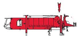
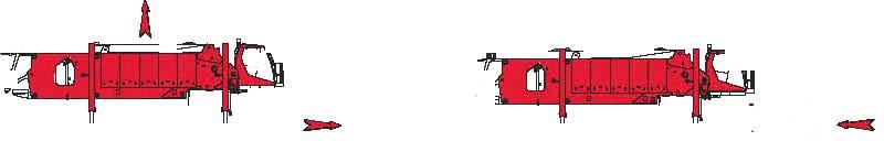
8 outline dimensions 37,5 m (3' ") 3,5 m (' ") 5,07 m (9' 5") 7, m (3' "),57 m (' 7"),0 m (' "),9 m (' 3"),7 m (5' "),5 m (5' 0"),07 m (' ") 3, m (' 5") 5,00 m (' 5") 5, m (7' "), m (33' ") 9.0 m (9' 7") R, m (33' 5") TAISWING 3,00 m (9' ") 3, m (' "), m (3' 9") 5, m (9' ") 5, m (5' 3"),05 m (5' "),5 m (5' 0"),5 m (5' 0")
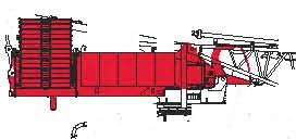
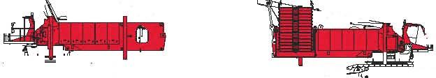
9 outline dimensions iftcrane ength 3,59 m ' " Width 3,00 m 9' " eight,9 m ' " Weight kg,35 lb Weight 0 0 kg,335 lb Note: Weight includes rotating bed rear section with pin pullers, counterweight, live mast, mast-hoist with wire rope, maximum hoist and whip lines on drums, Cummins QSX5 powerplant upperworks jacking system, full hydraulic fluid reservoir, and half tank of fuel. Weight is with upperworks jacking system removed. 9 Carbody & Rotating Bed ength 7,9 m 5' " Width 3,00 m 9'" eight 3,33 m ' 0" Weight 3 99 kg 95,900 lb Note: Weight includes rotating bed adapter frame with bearing turntable, four swing drives, and carbody. Upperworks Jacks x ength 3,9 m ' " Width, m 3' 9" eight 0,3 m ' " Weight 7 kg,700 lb Note: Shown in horizontal, retracted shipping position. Crawlers x ength, m 3' 9" Width,0 m 7' 3" eight,07 m ' " Weight 0 03 kg,5 lb W W Carbody Counterweight Tray x ength, m ' " Width,39 m 7' " eight,30 m ' " Weight 700 kg,000 lb ower Counterweight x ength,59 m ' " Width 3,5 m ' " eight 0,5 m ' " Weight 9 95 kg,000 lb Option
10 outline dimensions Upper Counterweight Tray x ength, m 9' " Width 3, m ' " eight,3 m 7' " Weight 5 5 kg,050 lb W W Upper Counterweight x ength,5 m ' " Width, m ' 7" eight 0, m ' " Weight kg,000 lb No. 5 Mast Butt & Top Package, Drum, Wire Rope, Equalizer x ength 5, m 9' 7" Width 3,00 m 9' " eight,79 m 9' " Weight 5 kg 57,75 lb No. 5 Mast Insert, m (0') & Straps x ength,30 m 0' " Width 3,00 m 9' " eight,9 m ' " Weight 3 50 kg,90 lb No. 5 Mast Insert, m (0') & Straps x ength,5 m 0' " Width 3,00 m 9' " eight,9 m ' " Weight 33 kg 3,90 lb No. 55 or No. 55A Butt, m (0') with Drum, Rigging Winch & Wire Rope x ength, m ' 9" Width 3,00 m 9' " eight 3, m ' " Weight 5 kg 57,75 lb Option
11 outline dimensions No. 55 or No. 55A Top 9, m (30') x ength,09 m 33' " Width 3,00 m 9' " eight 3, m ' " Weight 737 kg 37,7 lb No. 55 or No. 55A Insert 3,0 m (') with Drum & Wire Rope x ength,35 m 0' " Width 3,00 m 9' " eight 3, m ' " Weight,3 kg 35,90 lb No. 55 or No. 55A Insert, m (0') x ength,35 m 0' " Width 3,00 m 9' " eight 3, m ' " Weight 0 kg,75 lb No. 55 or No. 55A Insert, m (0') x ength,37 m 0' 7" Width 3,00 m 9' " eight 3, m ' " Weight 3 kg,5 lb No. 55/79A Transition Insert & Straps, m (0') x ength,37 m 0' 7" Width 3,00 m 9' " eight 3, m ' " Weight 90 kg 9,0 lb No. 79A Top 9, m (30') x ength,05 m 33' 0" Width 3,00 m 9' " eight 3, m ' " Weight 5 kg 7,35 lb Option
12 outline dimensions No. 79 Insert, m (0') x ength,7 m 0' 7" Width 3,00 m 9' " eight 3,09 m ' " Weight kg 7,35 lb No. 79 Insert, m (0') x ength,37 m 0' 7" Width 3,00 m 9' " eight 3,09 m ' " Weight 5 97 kg 3, lb No. 79 uffing Jib Butt, m (0') x ength,3 m ' 9" Width 3,00 m 9' " eight 3,09 m ' " Weight 3 57 kg 9, lb No. 79 uffing Jib Main Masts, m (0') x ength,5 m 53' 0" Width,5 m ' 3" eight,3 m 7' 9" Weight 5 kg 3,5 lb No. uffing Jib Butt, m (0') x ength,7 m ' " Width 3,00 m 9' " eight 3,00 m 9' " Weight 5 9 kg,50 lb No. uffing Jib Masts, m (0') x ength,5 m 53' 0" Width,5 m ' 3" eight,3 m 7' 9" Weight 5 kg 3,5 lb Option
13 outline dimensions No. Top 9, m (30') & Wire Rope Guide, Straps, ower Point x ength,0 m 33' 0" Width,59 m ' " eight,90 m 9' " Weight 5 57 kg,75 lb 3 No. uffing Jib Insert 3,0 m (') x ength 3.3 m ' 7" Width,59 m ' " eight,59 m ' " Weight 57 kg,90 lb No. uffing Jib Insert, m (0') x ength, m 0' 7" Width,59 m ' " eight,59 m ' " Weight 5 kg 3,5 lb No. uffing Jib Insert, m (0') x ength,3 m 0' 7" Width,59 m ' " eight,59 m ' " Weight 5 kg 5,0lb No. 79A Fixed Jib Butt, m (0') x ength,5 m ' 5" Width 3,00 m 9' " eight 3,0 m 9' " Weight kg 9,0 lb No. 79A Fixed Jib Strut, m (0') x ength 9, m 3' " Width,97 m 9' 9" eight.9 m 9' 7" Weight kg,0 lb Option


14
15
16 performance data Wire Rope engths - Tandem Drums - mm oist ine No. 55 or No. 55A or and Fixed Jib ength Whip ine Drum 3 ( Part of ine) Drum 3 ( Parts of ine) oist ine Drum Drum Total Parts of ine oist Reeving for Main oad Block Two ead ines - mm No. 55 or No. 55A No. Parts of ine Maximum oad kg (lb) 30 7,000 m (ft) m (ft) m (ft) m (ft) ,500 3, () 9 30 (5) 579 (900) 579 (900) ,000,7 () 99 (35) 5 (75) 7 (00) 7 (00) ,00, () (375) (550) 7 (500) 7 (500) ,000 5,9 () (00) 3 (00) 53 (00) 53 (00) 55 00,00,00,0 (00) 37 (50) 0 (75) 53 (00) 53 (00) 7, (0) 5 (500) (75) 9 (3000) 9 (3000) 73, (0) (55) 3 (775) , (0) 75 (575) 59 (50) ,3 (0) 3 (00) 7 (900) , 9 (50) 97 (975) ,5 (30) 3 (700) 3 (5) NOTE: Above hoist line lengths are based on tandem drums both reeved to the main load block. Each drum is dead-ended in main load block reeving. Total parts of line requires using both drums and. oist and whip line lengths will allow hook to touch ground. When block travel below ground is required, add additional rope equal to parts of the line times the added travel distance. oisting distance or line pull may be limited when block travel below ground is required. Wire Rope engths - Single oist Drum - mm oist ine No. 55 or No. 55A ength 3, (),7 (), () 5,9 (),0 (00) 7, (0) 73, (0) 79, (0) 5,3 (0) 9, 97,5 (30) m Part Whip ine - Drum or 3 oist ine - Drum (ft) (35) (375) (00) (50) (500) (55) (575) (00) (50) (700) Part Maximum Parts of ine For Full oisting m (ft) (5) (75) (550) (00) (75) (75) (775) (50) (900) (975) (5) m (ft) (3900) (500) (00) (00) (00) (00) (00) (00) (00) (00) (00) Range NOTE: Above hoist line lengths are based on single part lead line. oist and whip line lengths will allow hook to touch ground. When block travel below ground is required, add additional rope equal to parts of the line times the added travel distance. oisting distance or line pull may be limited when block travel below ground is required. oist Reeving for Main oad Block Single ead ine - mm No. 55 or No. 55A No. Parts of ine 0 30 Maximum oad kg (lb) , , , , , , , , , , , , , ,300 5,00 99,00
17 performance data Wire Rope engths - Tandem Drums - 3 mm oist ine No. 55 or No. 55A ength 3, (),7 (), () 5,9 (),0 (00) Drum 3 ( Part of ine) m Whip ine (ft) (35) (375) (00) (50) Drum 3 ( Parts of ine) m (ft) (5) (75) (550) (00) (75) m Drum oist ine (ft) (900) (900) (00) (00) Drum m (ft) (900) (900) (00) (00) Total Parts of ine 0 0 oist Reeving for Main oad Block Two ead ines - 3 mm No. 55 or No. 55A No. Parts of ine 0 Maximum oad kg (lb) , , , , ,7, ,3,00 7 7, (0) 5 (500) (75) , (0) (55) 3 (775) , (0) 75 (575) 59 (50) 73 (00) 73 (00) 5,3 (0) 3 (00) 7 (900) 79 (00) 79 (00) 9, 9 (50) 97 (975) 79 (00) 79 (00) 97,5 (30) 3 (700) 3 (5) 79 (00) 79 (00) NOTE: Above hoist line lengths are based on tandem drums both reeved to the main load block. Each drum is dead-ended in main load block reeving. Total parts of line requires using both drums and. oist and whip line lengths will allow hook to touch ground. When block travel below ground is required, add additional rope equal to parts of the line times the added travel distance. oisting distance or line pull may be limited when block travel below ground is required. Wire Rope engths - Single oist Drum - 3 mm oist ine No. 55 or No. 55A ength 3, (),7 (), () 5,9 (),0 (00) 7, (0) 73, (0) 79, (0) 5,3 (0) 9, 97,5 (30) m Whip ine - Drum or 3 oist ine - Drum Part (ft) (35) (375) (00) (50) (500) (55) (575) (00) (50) (700) Part Maximum Parts of ine For Full oisting m (ft) (5) (75) (550) (00) (75) (75) (775) (50) (900) (975) (5) m (ft) (3700) (3700) (3700) (3700) (3700) (3700) (3700) (3700) (3700) (3700) (3700) Range 0 NOTE: Above hoist line lengths are based on single part lead line. oist and whip line lengths will allow hook to touch ground. When block travel below ground is required, add additional rope equal to parts of the line times the added travel distance. oisting distance or line pull may be limited when block travel below ground is required. oist Reeving for Main oad Block Single ead ine - 3 mm No. 55 or No. 55A No. Parts of ine 0 Maximum oad kg (lb) 70 97, ,00 3 9, ,00 350, , , , , ,00 50,033, ,, ,97, ,77,500
18 performance data Wire Rope Specifications 5: Safety Factor - 3 mm oist ine - No. 55 or No. 55A Function MCC Part Number Rotation Resistant, Right and ang ay Wire Rope with Spelter Button (except 795) and Pad Eye oist ine (Drum ) A0005 oist or Whip ine (Drum ) A0005 Whip ine (Drum 3) 795 Maximum Spooling Capacities Drum (oist ine) 3 mm Wire Rope* Drum (oist or Whip ine) (3 mm) Wire Rope* Drum 3 (Whip ine) mm Wire Rope 05 m (3,330 ft) 9 ayers 05 m (3,330 ft) 9 ayers 579 m (,900 ft) ayers Size Wire Rope Minimum Breaking Strength Maximum oad Per ine 3 mm 0 kg (,000 lb) 3 mm 0 kg (,000 lb) kg (,00 lb) mm 370 kg (79,00 lb) 3 kg (30,000 lb) *7 m (3 ft) is deducted from maximum spooling capacities for 3 dead wraps per drum. Refer to Drum and agging Chart No. 5-A and oad Block Reeving Folio No. 03 Approximate Weight 5.57 kg/m (3.7 lb/ft) 5.57 kg/m (3.7 lb/ft). kg/m (.7 lb/ft) Wire Rope engths - Single oist Drum - mm oist ine No A ength 3, (),7 (), () 5,9 (),0 (00) 7, (0) 73, (0) 79, (0) 5,3 (0) 9, 97,5 (30) 3, (30) 9,7 (30) 5, (30),9 (00) m Whip ine - Drum or 3 oist ine - Drum Part (ft) (35) (375) (00) (50) (500) (55) (575) (00) (50) (700) (75) (775) (00) (50) m Part NOTE: oist and whip line lengths will allow hook to touch ground. When block travel below ground is required, add additional rope equal to parts of the line times the added travel distance. oisting distance or line pull may be limited when block travel below ground is required. (ft) (5) (75) (550) (00) (75) (75) (775) (50) (900) (975) (5) (75) (50) (0) (75) m (ft) (3900) (500) (00) (00) (00) (00) (00) (00) (00) (00) (00) (00) (00) (00) (00) Maximum Parts of ine For Full oisting Range oist Reeving for Main oad Block Single ead ine - mm No A No. Parts of ine 0 30 Maximum oad kg (lb) , , , , , , , , , , , , , , ,000,000
19 performance data Wire Rope Specifications 5: Safety Factor - mm No. 55 or No. 55A and No A Function MCC Part Number Rotation Resistant, Right and ang ay Wire Rope with Pad Eye oist ine (Drum ) 795 oist or Whip ine (Drum ) 795 Whip ine (Drum 3) 795 Maximum Spooling Capacities Drum (oist ine) mm Wire Rope* Drum (oist or Whip ine) ( mm) Wire Rope* Drum 3 (Whip ine) mm Wire Rope 0 m (,73 ft) ayers 0 m (,73 ft) ayers 579 m (,900 ft) ayers 9 Size Wire Rope Minimum Breaking Strength Maximum oad Per ine Approximate Weight mm 370 kg (79,00 lb). kg/m (.7 lb/ft) mm 370 kg (79,00 lb) 0 kg (35,00 lb). kg/m (.7 lb/ft) mm 370 kg (79,00 lb) 3 kg (30,000 lb). kg/m (.7 lb/ft) *7 m (3 ft) is deducted from maximum spooling capacities for 3 dead wraps per drum. Refer to Drum and agging Chart No. 5-A and oad Block Reeving Folio No. 003 for No. 55 or 55A. Refer to Drum and agging Chart No. 5-A and oad Block Reeving Folio No. 03 for No A. Drum And agging Chart - iftcrane Application Drum Number and ocation Drum Part Number Drum Type Drum Diameter Drum Width Grooved agging Part Number agging Diameter Minimum Wire Rope Size oist Drum ( Insert) A053 Bare 5 mm (5-3/") mm (9-/") A050 A mm (-/") 7 mm (-/") mm 3 mm oist or Whip Drum ( Butt) A053 Bare 5 mm (5-3/") mm (9-/") A050 A mm (-/") 7 mm (-/") mm 3 mm Whip Drum 3 (Rotating Bed) A0530 Grooved mm (5-/") mm (3-3/") mm Drum Identification Drum Number Function Main oad Drum Standard Main/Auxiliary oad Drum Standard Whip oist Standard oist Standard Mast oist Standard uffing Jib Drum Optional Rigging Winch Optional (not shown, located in Butt) 5 3
20 performance data 0 Wire Rope engths - Single oist Drum - 3 mm oist ine No A ength 3, (),7 (), () 5,9 (),0 (00) 7, (0) 73, (0) 79, (0) 5,3 (0) 9, 97,5 (30) 3, (30) 9,7 (30) 5, (30),9 (00) m Whip ine - Drum or 3 oist ine - Drum Part (ft) (35) (375) (00) (50) (500) (55) (575) (00) (50) (700) (75) (775) (00) (50) Part Maximum Parts of ine For Full oisting m (ft) (5) (75) (550) (00) (75) (75) (775) (50) (900) (975) (5) (75) (50) (0) (75) m (ft) (900) (3500) (3700) (3700) (3700) (3700) (3700) (3700) (3700) (3700) (3700) Range 0 NOTE: oist and whip line lengths will allow hook to touch ground. When block travel below ground is required, add additional rope equal to parts of the line times the added travel distance. oisting distance or line pull may be limited when block travel below ground is required. Wire Rope Specifications 5: Safety Factor - 3 mm oist ine - No A Function MCC Part Number Size Wire Rope Minimum Breaking Strength Maximum oad Per ine Approximate Weight oist ine (Drum ) A mm 0 kg (,000 lb) 5.57 kg/m (3.7 lb/ft) Maximum Spooling Capacities Drum (oist ine) 3 mm Wire Rope* Drum (Whip ine) 3 mm Wire Rope* Drum 3 (Whip ine) mm Wire Rope Rotation Resistant, Right and ang ay Wire Rope with Spelter Button (except 795) and Pad Eye 05 m (3,330 ft) 9 ayers 05 m (3,330 ft) 9 ayers 579 m (,900 ft) ayers oist or Whip ine (Drum ) A0005 *7 m (3 ft) is deducted from maximum spooling capacities for 3 dead wraps per drum. Refer to Drum and agging Chart No. 5-A and oad Block Reeving Folio No mm 0 kg (,000 lb) kg (,00 lb) 5.57 kg/m (3.7 lb/ft) Whip ine (Drum 3) 795 mm 370 kg (79,00 lb) 3 kg (30,000 lb). kg/m (.7 lb/ft) oist Reeving for Main oad Block Single ead ine - 3 mm No A No. Parts of ine 0 Working Weight 30,5 m (0') No. 5 Mast with 3, m (') No. 55 or No. 55A Main, Upper Point, t (00 USt) hook block. 30,5 m (0') No. 5 Mast with 3, m (') No. 55/79A Main Upper Point, 5 t (500 USt) hook block. No. Parts of ine * 0* Maximum oad kg (lb) 70 97, ,00 3 9, ,00 350, , , , , , ,000,000 kg (lb) (,53,70) 70 3 (,7,930) Typical working weight includes hydraulic reservoir full, fuel half-full, drums with standard lengths of wire rope, upper boom point and 7 t (30 USt) hook and weight ball. oist Reeving for Jib oad Block Single ead ine - mm No A and No. 55* or No. 55A* Maximum oad kg (lb) , , , , ,00 93, , ,00 50* 7,00* * 50,00* * Only for No. 55 or No. 55A with fixed jib 79A
21 performance data Wire Rope engths - mm oist ine iftcrane - uffing Jib No. on No A ength iffing Jib ength,0 () 7, (0) 70, (30) 73, (0) 7, (50) 79, (0) 73, (70) 79, (0) 5,3 (90) 9, 9,5 (3) 97,5 (30) 0, (330) 3, (30),7 (350) 9,7 (30), (370) 5, (30),9 (390),9 (00) 5,0 (),0 (0) 3, (30) 3, (0) 37, (50), (0) 3,3 (70),3 (0) 9, (90) 5, (500) 55,5 (5) 5,5 (50) ength m (ft), () 5,9 (),0 (00) 7, (90) Whip ine - Drum or 3 Part (0) 5 (500) 5 (50) 5 (50) 7 (50) 77 (50) 3 (00) 9 (0) 95 (0) 0 (0) 07 (0) 3 (700) 9 (70) (70) 3 (70) 3 (70) (00) 50 (0) 5 (0) (0) (0) 7 (900) 0 (90) 7 (90) 93 (90) 99 (90) 305 (00) 3 (0) 37 (0) 33 (0) 39 (0) 335 (0) NOTE: Whip line lengths given in table will allow hook to touch ground. When hook travel below ground is required, add additional rope equal to parts of the line times the added travel distance. oisting distance or line pull may be limited when block travel below ground is required. 33,5 () 39, (30) Part (75) 9 (750) 3 (775) 5 (5) 59 (50) 7 (75) 7 (900) (95) 90 (950) 305 (00) 3 (5) 30 (50) 3 (75) 335 (0) 33 (5) 35 (75) 3 (0) 373 (5) 3 (50) 39 (75) 0 (35) (350) 9 (375) 7 (0) 3 (5) (50) 57 (500) 5 (55) 7 (550) 0 (575) (0) 95 (5) 5,7 (50) 5, (70) 57,9 (90) Wire Rope engths - mm oist ine iftcrane - uffing Jib No. on No A oist ine Drum Wire m (,00 ft),0 () uffing Jib,3 (70), (0) 7, (90) 30,5 (0) 33,5 () 3, () 39, (30),7 () 5,7 (50), () 5, (70) 5,9 () 57,9 (90),0 (00),0 () 7, (0) 70, (30) 73, (0) 70, (30),7 () Wire Rope engths - Single oist Drum - mm oist ine iftcrane - Fixed Jib No. 79A on No. 55 or No. 55A oist ine - Drum 7, (50), (),3 (70) ength, (90) 5,9 () 9,5 (3),0 (00) 7, (0) 73, (0) 79, (0) 5, (0) NOTE: Whip line lengths given in table will allow hook to touch ground. When block travel below ground is required, add additional rope equal to parts of the line times the added travel distance. oisting distance or line pull may be limited when block travel below ground is required. Wire Rope engths - Single oist Drum mm oist ine iftcrane - Fixed Jib No. 79A on No. 55 or No. 55A oist ine - Drum Whip ine Maximum Parts of ine Drum or 3 Part ength Jib ength Part oist ine Drum 5, (50),3 (70) 7, (90) 33,5 (),7 () 0 50 (0) 75 (575) 5 (5), () 50 (0) 3 (00) 7 (900) 5,9 () 3 (00) 9 (50) 90 (950),0 (00) 3 (00) 9 (50) 90 (950) 7, (0) (00) 9 (50) 90 (950) NOTE: oist and whip line lengths will allow hook to touch ground. When block travel below ground is required, add additional rope equal to parts of the line times the added travel distance. oisting distance or line pull may be limited when block travel below ground is required. Maximum Parts of ine oist ine Jib ength Drum 3 3 (00) 33 (700) NOTE: Above hoist line lengths are based on single part lead line.
22 performance data Performance for Main oist (Drum #) and also Auxiliary oist (Drum #) mm Wire Rope - ayers Maximum Working - agging Groove Root Diameter.5 " Single ine Speed in per Minute ayer Single ine Pull Single ine Pull kg (lb) 37 mm (. ) 399 mm (5.7 ) 3 7 mm (. ) 55 mm (7.9 ) 5 3 mm (9.0 ) 5 mm (0. ) 7 53 mm (. ) 5 mm (.3 ) 9 59 mm (3. ) 5 mm (. ) 50 mm (5. ) 0 (0) 9 (309) (333) 9 (35) (379) 3 (0) 30 () 37 (9) (7) 5 (9) 5 (59) 5 (5) 53 (,000) 90 (95) 9 (3) 3 (337) 9 (35) 5 (37) (399) (9) 3 (39) (59) (79) 5 (9) 9 07 (0,000) 5 (0) 9 (99) 97 (3) 3 (33) (35) 3 (37) 9 (39) 3 (05) 9 () 33 (3) 3 () 3 07 (30,000) () (3) 9 (93) 9 (97) 9 (30) 93 (30) 95 (3) 9 (35) 9 (30) 99 (3) 0 (39) 39 (35,00) 75 (7) 77 (5) 7 (5) 0 () (5) (70) (7) 5 (79) (3) () 9 (9) Performance for Main oist (Drum #) and also Auxiliary oist (Drum #) 3 mm Wire Rope - 9 ayers Maximum Working - agging Groove Root Diameter.5 Single ine Speed in per Minute ayer Single ine Pull Single ine Pull kg (lb) 37 mm (. ) 0 mm (.0 ) 3 37 mm (7. ) 70 mm (.5 ) mm (9.7 ) 533 mm (.0 ) 7 5 mm (.3 ) 570 mm (3.5 ) 9 30 mm (. ) 0 (0) 95 (3) 3 (33) (3) 9 (39) 7 (7) 35 () (7) 5 (97) (5) 53 (,000) 90 (9) 9 (30) 5 (3) (3) 9 (39) (5) 3 (3) (0) 7 (3) 9 07 (0,000) () 9 (303) 99 (3) 5 (35) (35) 7 (35) 3 (0) 9 (3) 33 (37) 3 07 (30,000) (7) 7 () 90 (9) 9 (99) 93 (305) 9 (3) 9 (35) 9 (30) 99 (35) (0,000) 9 () 7 (33) 73 (3) 7 (3) 7 () 77 (5) 79 (59) 0 () 7 (5) 35 (,00) (99) (03) 3 (0) 5 (3) 7 () (3) 9 () 7 (3) 73 (39) Performance for Whip (Drum #3) - mm Wire Rope ayers Maximum Working - Drum Barrel Groove Root Diameter 5.5 " Single ine Speed in per Minute ayer Single ine Pull Single ine Pull kg (lb) 0 (0) (5,000) 53 (,000) 0 (5,000) 9 07 (0,000) 30 (5,000) 335 mm (3. ) 5 (79) (7) 7 (55) 7 () () 57 () 33 mm (.3 ) 9 (30) () (75) 0 () 9 () 59 (93) 3 39 mm (5. ) 99 (35) 9 (3) 90 (9) 5 (7) 70 (3) 0 (97) 9 mm (.5 ) (30) (330) 95 (3) 9 (9) 7 (35) (0) 5 7 mm (7. ) 3 (37) 7 (35) (33) 90 (9) 73 (0) 3 (0) 0 mm (. ) (395) 3 (37) (3) 9 7 () () mm (9. ) (9) 9 (39) (3) 93 (305) 7 (9) (5) 53 mm (0.9 ) 35 () (3) 7 (33) 9 (309) 77 (53) 9 () 3 07 (30,000) 5 () 5 (70) 53 (75) 55 (79) 5 () 57 () 59 (93) 0 (97)
23 boom combinations No. 55 or No. 55A Combinations ength 3, () Inserts, m (0 ft) 3,0 m ( ft), m (0 ft) No A Combinations ength 3,0 m ( ft) 55* 79 Transition, m, m, m, m (0 ft) (0 ft) (0 ft) (0 ft), m (0 ft) Inserts No A 3,7 () 3, (), (),7 () 5,9 (), (),0 (00) 3 5,9 () 7, (0) 3,0 (00) 73, (0) 7, (0) 79, (0) 73, (0) 5,3 (0) 5 79, (0) 9, 5 5,3 (0) 3 97,5 (30) 9, 3 NOTE: 3, m (') basic boom consists of, m (0') butt, 3,0 m (') insert with drum,, m (0') insert,, m (0'), and 9, m (30') top. May use, m (0') No. 55 insert with or without sheaves. 97,5 (30) 3, (30) 9,7 (30) 5, (30) 5 5 9, m (30 ft) No. 79A Top, m (0 ft) No. 79 Insert 9, m (30 ft) No. 55 or No. 55A Top,9 (00) NOTE: 3, m (') basic boom consists of, m (0') butt, 3,0 m (') insert with drum,, m (0') insert,, m (0'), and 9, m (30') top. May use, m (0') No. 55 insert with or without sheaves., m (0 ft) No. 79 Insert, m (0 ft) No. 55 Insert, m (0 ft) No. 79 Insert No. 55 or No. 55A eavy-ift 97,5 m (30 ft), m (0 ft) No. 55 Insert, m (0 ft) No. 55 Insert No A eavy-ift,9 m (00 ft), m (0 ft) No. 79 Insert, m (0 ft) No. 79 Insert, m (0 ft) No. 55 Insert, m (0 ft) No. 79 Insert, m (0 ft) No. 55 Insert, m (0 ft) No Transition Insert, m (0 ft) No. 55 Insert, m (0 ft) No. 55 Insert 3,0 m ( ft) No. 55 Insert, m (0 ft) No. 55 or Butt Model 00 No. 55 or No. 55A eavy-ift Main 97,5 m (30 ft) Model 00 No A eavy-ift Main,9 m (00 ft), m (0 ft) No. 55 Insert, m (0 ft) No. 55 Insert 3,0 m ( ft) No. 55 Insert, m (0 ft) No. 55 Butt
24 boom combinations Jib ength No. 79A Fixed Jib Combinations 7, (50) 33,5 (70) 39, (90) 5,7 () Inserts, m, m (0 ft) (0 ft) , m (30 ft) No. 79A Jib Top No. 79A Fixed Jib 7, m (90 ft), m (0 ft) No. 79 Jib Insert, m 0 ft) No. 79 Jib Butt No. 55 or No. 55A eavy-ift 0,0 m (00 ft) 9, m (30 ft) No. 55 Top, m (0 ft) No. 55 Insert, m (0 ft) No. 55 Insert, m (0 ft) No. 55 Insert, m (0 ft) No. 55 Insert 3,0 m ( ft) No. 55 Insert, m (0 ft) No. 55 Butt Model 00 No. 79A Fixed Jib on No. 55 or No. 55A eavy-ift Main,0 m (90 ft)
25 boom combinations No. uffing Jib Combinations uffing Jib ength Inserts, m (0 ft) 3,0 m ( ft), m (0 ft) No. 79A uffing Jib Combinations uffing Jib ength Inserts, m, m (0 ft) (0 ft) 5,3 (70) 7, (90) -, (0) 33,5 () 7, (90) 30,5 (0) 33,5 () 9, m (30 ft) No. Jib Top 39, (30) 5,7 (50) 5, (70) 9, m (30 ft) No. 79A Jib Top 3, () 39, (30),7 (), m (0 ft) No. Jib Insert 57,9 (90),0 () 70, (30) 3 3, m (0 ft) No. 79 Jib Insert 5,7 (50), () 5, (70) 5,9 () 57,9 (90),0 (00),0 () 7, (0) 70, (30) 73, (0) No. uffing Jib 73, m (0 ft), m (0 ft) No. Jib Butt, m (0 ft) No. Jib Insert, m (0 ft) No. Jib Insert, m (0 ft) No. Jib Insert 3,0 m ( ft) No. Jib Insert 7, (50),3 (70),3 (90) 9,5 (3) No. 79A uffing Jib 9,5 m (3 ft) 5 5, m (0 ft) No. 79 Jib Insert, m (0 ft) No. 79 Jib Insert, m (0 ft) No. 79 Jib Insert, m (0 ft) No. 79 Jib Insert 9, m (30 ft) No. 79A Top, m (0 ft) No. 79 Jib Insert No A eavy-ift 5,3 m (0 ft), m (0 ft) No. 79 Insert, m (0 ft) No. 79 Insert 3,0 m ( ft) No. 79 Jib Insert, m (0 ft) No. 79AJib Butt, m (0 ft) No 79 Insert, m (0 ft) No Insert No. 55 or No. 55A eavy-ift 5,9 m ( ft) 9, m (30 ft) No. 55 Top, m (0 ft) No. 55 Insert, m (0 ft) No 55 Insert 3,0 m ( ft) No. 55 or No. 55A Insert, m (0 ft) No. 55 or No. 55A Butt Model 00 No. uffing Jib on No A eavy-ift Main 5,5 m (50 ft), m (0 ft) No. 55 or No. 55A Insert, m (0 ft) No. 55 or No. 55A Insert, m (0 ft) No. 55 Insert, m (0 ft) No. 55 Insert 3,0 m ( ft) No. 55 Insert, m (0 ft) No. 55 Butt Model 00 No. 79A uffing Jib on No. 55 or No. 55A eavy-ift Main 9,3 m (90 ft)


26
27 heavy-lift load charts iftcrane Capacities No. 55 or No. 55A with 30,5 m (0') Mast No kg (5,000 lb) Counterweight 5 50 kg (30,000 lb) Carbody Counterweight 30 Rating kg (lb) x ,3 (),0 () 9,0 (30),0 (3),0 (0),0 (5),0 (50),0 (0) 3, () 00,0 (3.) 5, (5.7) 5, (995.9) 375,5 (30.) 33, (75.) 9,5 (57.7) 50,0 (53.),3 (7.),7 () 57,5 (99.) 373,9 (.) 3,3 (7.5) 90,3 (5.9), (50.) 7,0 (9.9), () (97.9) 37, (.5) 30, (73.),7 (5.5) 7, (577.0) 5,5 (.5) 5,9 () 370,5 (.9) 33, (73.) 7,3 (.) 5, (573.),0 (3.3),0 (00) 370, (.7) 337,7 (73.),5 (.),9 (57.0),9 (.5) 7, (0) 33, (7.) 5,0 (3.) 3,3 (5.5), (57.9) 73, (0) (75.9) 3,9 (0.),3 (5.),5 (55.5) 79, (0),5 (3.7) 0, (5.) 0, (5.7) 5, (0), (33.7) 39, (559.) 07, (9.0) 9, 3, (55.0) 05, (5.) 97,5 (30) 3,3 (5.) 0, (5.),0 (70) 7, (39.) 7,3 (39.9) 9, (3.5),3 (35.3) 7,5 (33.) 5, (379.),7 (377.) 3,0 (373.5),7 (3.7) 59,9 (3.),0 (3.9),0 (0),0 (90) 30,0 (0) 55, (33.3),0 (.3),0 (5.7) 5,3 (333.) 5,3 (.7) 3,3 (.) 5, (330.5), (.), (.) 5,3 (37.) 3, (79.9), (39.) 50, (35.9),7 (7.9), (3.), (3.7),5 (7.) 9,3 (35.) 7,7 (39.),7 (7.3), (33.) 5,9 (35.) 9, (70.) 7, (3.3),7 (3.) 7,9 (7.), (.),9 (30.), (3.7),7 (.),9 (30.7), (3.7),9 (5.3) 3,0 () 3,0 () 0,0 (30),0 () 9, (3.5),9 (7.) 9, (.0),3 (5.9) 73,3 (.) 7, (5.7) 93, (09.7) 5,3 (3.) 7,3 (.9), (3.) 9, (07.0), (.9) 7, (59.) 5, (.9) 9,3 (05.) 3,5 (79.) 70,5 (57.9) 5,0 (39.) 9,9 (0.), (7.5) 9, (5.) 3,5 (3.) 9, (00.9), (7.), (5.),7 (3.5) 7, (97.7) 79,7 (7.3),7 (9.5), (3.), (95.5) 7,7 (9.0) 5, (7.) 0, (.7) 5, (9.) 77, (5.),0 (3.7) 5,5 (5.) 5,3 (9.) 77, (.), (.) 5,7 (5.) 50,0 () (.),3 (.7) 7, (.),3 (7.) 5, (5.3) 3,9 (.), (99.), (95.),3 (9.) 5,0 (),7 (9.), (.) 39, (.9) 3,9 (3.0) 37,3 (79.5) 3, (77.) 3, (73.5) 3,7 (73.) 0,0 (00), 3, (7.3) 30,7 (5.) 9, (.9), (59.5), (55.9), (5.),0 (0) 7,0 (0) 7,0 (50) 7,0 (55),3 (50.),3 (.5) 5, (3.), (5.) (.9), (3.), (9.), (3.0),7 (9.9) 9,0 (39.), (.9), (.) (5.) 9,3 (0.), (5.) (9.5) (.) Meets ANSI B30.5 Requirements - Capacities do not exceed 75% of static tipping load. NOTICE: This capacity chart is for reference only and must not be used for lifting purposes.

28
29 heavy-lift load charts iftcrane Capacities - 00 No A with 30,5 m (0') Mast No kg (5,000 lb) Counterweight 5 50 kg (30,000 lb) Carbody Counterweight 30 Rating kg (lb) x , (),7 (), (),0 (00) 7, (0) 73, (0) 5,3 (0) 9, 97,5 (30) 9,7 (30) 5, (30),9 (00) 7,9 () 53,5 (00.0) 9, (30) 53,5 (00.0) 53,5 (00.0),0 (939.3),0 (3) 9, (9.) 7,7 (.),0 (.),0 (0),0 (5),0 (50),0 (0) 39,5 (75.5) 97, (70.) 55, (595.), (5.5) 3, (755.7) 9, (7.9) 5, (593.) 3, (3.) 3, (75.0) 9, (.) 53, (590.5), (0.) 30,7 (750.0) 9, (3.5) 5, (59.), (79.) 309, (3.) 7, (7.5) 5, (5.7) 0, (77.) (33.7),0 (599.) 35, (53.9), (0.5) 0,7 (.0),9 (.), (0.) 9,0 (30.5) 77,3 (33.) 77, (397.5) 7,3 (3.3) 35,3 (9.3) (57.) (0.9) 0,0 (70) 99,0 (07.) 9,0 (05.) 9, (0.) 9, (0.3) 95,3 (399.) 9, (39.) 9,7 (35.) 59,9 (33.) 5,7 (3.) 33,7 (.),0 (5.) 99, (0.),0 (0),0 (90) 30,0 (0),5 (39.7),0 (99.),0 (5.9), (37.7) 5, (9.) 9,5 (57.) 59,3 (3.),7 (9.), (55.) 5,7 (33.5), (9.),5 (55.7) 57,9 (3.7) 3, (95.0),0 (5.5) 57,5 (30.9) 3, (9.7) 7, (5.) 3, (3.) 33,7 (0.9),5 (5.) 35, (93.) 5, (3.7),0 (39.) 7, (77.),7 (.9) 3, (5.5),7 (9.0),0 (.) 9, (99.9) 9,5 (3.) 0,3 (09.), (.3) 99,5 (9.3) 95, (99.), (7.) 3,0 () 9, (9.) 9,7 (99.9) 9,7 (97.9) 9, (97.) 9, (9.) 90,9 (95.9) 9, (93.5) 9,0 (90.7) 7, (9.) 7,7 (.5) 7,9 (55.9) 7, (.7),0 () 7, (.0) 73, (5.) 73,3 (57.9) 7,7 (5.7) 7,5 (5.) 7, (53.7) 75,5 (5.) 70,0 (50.7) 5, (.9) 0,9 (3.) 57,0 (3.),0 () 59,9 (9.0) 59,9 (9.0) 59,3 (7.) 59, (7.3) 5,0 (.) 57, (.9) 5, (.7) 5,9 (.0) 5, (3.),9 (5.) 5,0 () 9,7 (.9) 9, (5.7) 9,0 (5.3) 7, (.) 7,0 (0.9), (99.7),7 (95.9) 3., (93.), (9.3) 0,0 (00), (.3),0 (.0) 39, (5.5) 39,0 (3.) 3, (.) 3,7 (7.) 35, (7.5) 35, (7.9),0 (0) 3,5 (73.) 33, (7.) 3,5 (9.) 3,0 (.) 30,3 (.) 9,3 (.5), (0.9) 7,0 (0),0 (59.) 7, (5.0), (5.),9 (53.),0 (50.9) 3, (9.3) 7,0 (0) 3,5 (50.0),7 (.), (7.) 0, (3.3) 9,5 (.), (39.),0 (0),0 9,0 (3) 9,0 (30), (39.),,3 (3.7),0 (30.) 3,5 (.3),9, (35.0),3 (.),7 (.) 9,3 (.7) 5,7 (33.9) 3, (.),5 (0.0), (.),9 (3.), (.) 9,7 7, Meets ANSI B30.5 Requirements - Capacities do not exceed 75% of static tipping load. NOTICE: This capacity chart is for reference only and must not be used for lifting purposes.
30
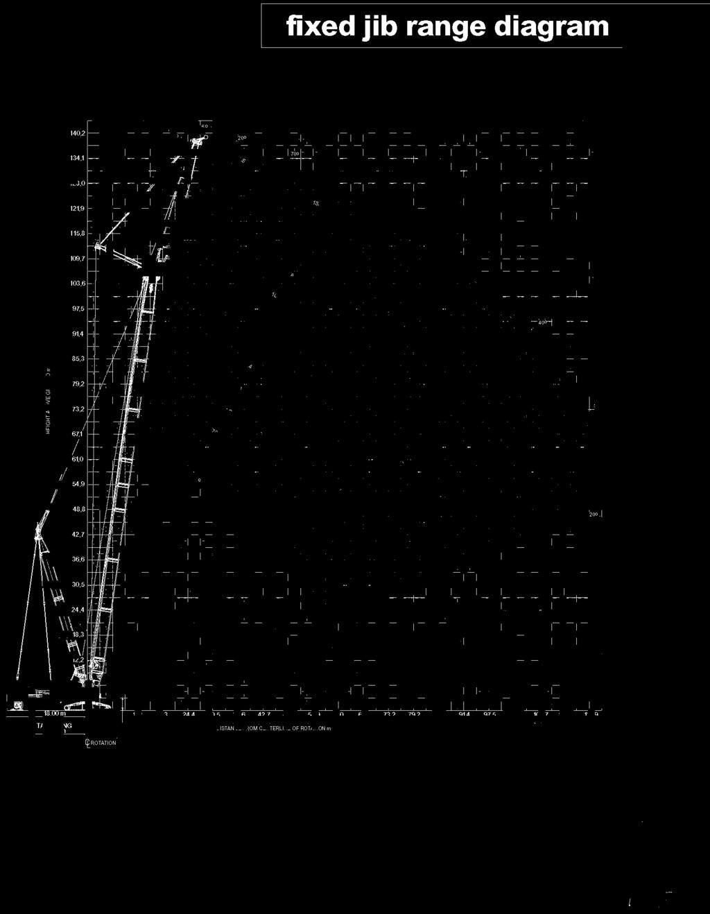
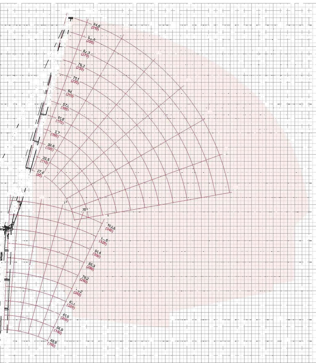
31 fixed jib load charts Jib ength 5, m (50 ft) iftcrane Jib Capacities - 00 Series Jib No. 79A with 5, m (50 ft) Strut on No. 55 or 55A with 30,5 m (0 ft) mast No. 5 39,500 kg (5,000 lb) Crane Counterweight 5,50 kg (30,000 lb) Carbody Counterweight 30 Rating kg (lb) x 000 3,7 (5), (55),0 (70),0 (90) 3,0 (),0 (),0 () 5,0 () 0,0 (00),7 () 95,0 (50.),0 (5.) 5,7 (30.) 33,3 (73.5) 79, (7.3) 0, (9.), (9.3) 3, (7.7) 5 Offset, () 5, (5.),3 (377.) 3, (70.0) 7,5 (.3) 5,9 (.0), (95.) 33, (70.0), (7.) 5,9 (),7 (50.0) 3,0 (37.3) 30,3 (.) 77, (5.3) 57,5 (.) 3, (9.7) 3,7 (.3),3 (3.9),0 (00) (50.5) 7, (370.9) 33,5 (3.) 79,3 (.5) 5, (.0),9 (9.0) 30, (3.5) 0, (.) 7, (0) 7,7 (7.), (.3) 7, (77.) 7,5 (5.) 5,7 (0.) 0,3 (9.),3 (0.3), (.),7 () 70, (390.7) 37,0 (.0),3 (7.), (3.9) 7, (0.),9 () 9,3 (3.5) 35, (7.3), (7.),0 (30.3), (9.) 3,5 (7.) 0 Offset 5,9 () (3.7) 3,7 (75.) 0, (7.9) 59, (7.7), (95.3) 33, (9.),3 (5.7),0 (00) 7, (3.0) 33,5 (73.0) 79,3 (9.) 5, (5.) 3,9 (93.) 3,3 (7.7), (.) 7, (0),5 (3.) 3, (70.) 7, (7.3) 57,5 (.),5 (90.) 30, (3.5) 9, (0.5) 3,0 (0) (.) 9, (.) (.), (0.9) 7,0 (0) 5, (),0 () 5,0 (),0 (00) 5, (),0 () 5,0 (),0 (00) 3,7 (5),0 (55) 9, (5.) (5.) Jib ength,3 m (70 ft),0 (70),0 (90) 3,0 (),0 (),0 () 5,0 () 0,0 (00),0 (0) 7,0 (0) 7, (3.) 35, (77.), (75.), (33.) 7, (.0) 3,7 (7.), (3.3) 33, (7.3) 0,5 (7.) 0, (30.0),3 (9.7) 35, (7.7) 5, (5.) (3.) 5, (30.) 3,5 30, (7.) (7.7) 79,3 (70.) 59, 5,0 (.9) (3.), (95.) 33, (70.) 3,3 (.3), (9.) 3,9 (37.) 77,9 (7.0) 3, (9.) 3, (7.5),9 (5.), (.) 73, (397.5) 39, (.) 5,0 (.),5 (3.) 9,5 (5.) 37,9 (0.) 73,0 (39.) 3,7 (.), (.) 3, (35.7),3 (3.0) 35, (77.) 5, (5.7) 37,9 3,5 (.) (79.5) 3,, (7.) (7.0),3,3 (33.3) (30.9) 7, (0.) 35, (75.0) 5,0 (5.),0 (97.9) 3, (7.7),0 (9.5), (9.7) Meets ANSI B30.5 Requirements - Capacities do not exceed 75% of static tipping load. NOTICE: This capacity chart is for reference only and must not be used for lifting purposes.
32 fixed jib load charts 3 iftcrane Jib Capacities - 00 Series Jib No. 79A with 5, m (50 ft) Strut on No. 55 or 55A with 30,5 m (0 ft) mast No kg (9,00 lb) Crane Counterweight 5 30 kg (,000 lb) Carbody Counterweight 30 Rating kg (lb) x Offset 0 Offset Jib ength 7, m (90 ft) 3,7 (5),0 (55),0 (70),0 (90) 3,0 (),0 (),0 () 5,0 () 0,0 (00),0 (0),7 () (50.),7 (3.) 35,9 (79.0),9 (7.0) 3, (35.3),7 (.) 37,7 (0.), (5.9),7 (39.), () 7,7 (3.7) 3,7 (7.),7 (75.3), (3.) 7, (0.) 3, (7.), (55.) 5,3 (3.5) 5,9 (), (3.9) 33, (73.) 0, (7.) 0, (9.3) 5, (97.) 3, (73.), (5.0) 3,5 (3.),0 (00) 5,0 (370.9) 3, (9.7) 79,0 (9.) 5,9 (5.9),3 (9.) 33,0 (9.3), (7.3), (.),7 (), (9.9), (.3), (.7) 5, (9.0) 37,7 (3.9), (.3),7,9 (), (.), (.5), (39.) 5, (.) 39, (.),5 (59.5),5 (39.3) 5,9 () 39,9 (.) 5,3 (.9), (37.3), (3.9) 37,0 (7.) 7,0 (5.) 5,0 (3.),0 (00) 3,5 (3.), (.3) 3,0 (3.) 7,5 (.) 35, (75.7) 5,7 (53.3) 3,9 (33.5) 7,0 (0), (0.0),7 (.) 9,9 (.), (.),7 (), () 5,9 (),7 (), () 5,9 () 3,7 (5),0 (55) Jib ength 33,5 m ( ft),0 (70),0 (90) 3,0 (),0 (),0 () 5,0 () 0,0 (00),0 (0) 7,0 (50) 9, (37.) 3, (0.) 3, (.0), (37.) 9,7 (.3) 3,7 (.5) 9,7 (.), (.),3 (3.) 35,3 (77.),7 (77.5),7 (3.), (3.0) 37, (79.) 7,9 (5.) 7,0 (0.),0 (7.) 7,9 (3.) 3,3 (75.3),7 (75.),5 (3.),9 (99.9) 35,7 (75.7),0 (5.) 5,0 (35.7),3 (9.5),3 (9.) 7, (5.0) 5, (.3),0 (7.3) 3, (7.3) 0,3 (7.),9 (9.) 7, (.),7 (.9) 5,5 (9.9) 39, (.5) 30,5 (.) 7,0 (.),0 (90.) 7, (.9) 5,9 (.0) 50, (7.5) 3, (.9) 9, (0.9) 7,3 (.) 7,7 (.5) Meets ANSI B30.5 Requirements - Capacities do not exceed 75% of static tipping load. NOTICE: This capacity chart is for reference only and must not be used for lifting purposes.

33
34 luffing jib load charts 3 iftcrane uffing Jib Capacities - 00 uffing Jib No. 79A on No. 55 or No. 55A With 30,5 m (0') Mast No kg (5,000 lb) Counterweight 5 50 kg (30,000 lb) Carbody Counterweight 30 Rating 7 Angle uffing Jib ength,0 m (90 ft),0 (55),0 (0) 0,0 (70),0 (0),0 (90) 30,0 (0) 3,0 (),0 (),0 () 5,0 () 0,0 (00),0 (00) 5,3 (537.) 00,3 (.0), (.0) 3, (353.5) 9,0 (30.),0 (7.) uffing Jib ength 33,5 m ( ft),0 (55),0 (0) 0,0 (70),0 (0),0 (90) 30,0 (0) 3,0 (),0 (),0 () 5,0 () 0,0 (00),0 (00) (57.7),3 (.9) 99,9 (.),9 (35.9), (30.), (73.),5 (9.5),0 (00),0 (00),0 (55),0 (55),0 (0),0 (0) uffing Jib ength 5,7 m (50 ft) 0,0 (70),0 (0),0 (90) 30,0 (0) 3,0 (),0 (),0 () 5,0 () 0,0 (00) 7,5 (30.),9 (3.),9 (30.7),5 (9.) 0,3 (7.0),7 (7.), (.7) uffing Jib ength 57,9 m (90 ft) 0,0 (70),0 (0),0 (90) 30,0 (0) 3,0 (),0 (),0 () 5,0 () 0,0 (00) 3, (9.) 7,9 (75.3) 9, (0.) 9,3 (.),0 (75.0) 7, (.7) 5, (.5) 7, (.) Meets ANSI B30.5 Requirements - Capacities do not exceed 75% of static tipping load. NOTICE: This capacity chart is for reference only and must not be used for lifting purposes.
35 luffing jib load charts iftcrane uffing Jib Capacities - 00 uffing Jib No. 79A on No. 55 or No. 55A With 30,5 m (0') Mast No kg (59,007 lb) Counterweight 5 50 kg (30,000 lb) Carbody Counterweight 30 Rating 35 5 Angle, () 5,9 (),0 (00), () 5,9 (),0 (00), (55) 0,7 (530.7), (55) uffing Jib ength 7, m (90 ft),0 (0) 0,0 (70),0 (0),0 (90) 30,0 (0) 3,0 (5),0 (),0 (50), (.0) 97,9 (0.0), (39.) 7, (305.), (9.) (7.0) 9, (0.) 59,9 (3.3) 5,9 (30.) 3,5 (7.) 5,3 (7.) 00,3 (399.3) 3, (33.5) 9,0 (300.),0 (5.3) (3.) uffing Jib ength 3,9 m (30 ft),0 (0) 0,0 (70),0 (0),0 (90) 30,0 (0) 3,0 (5),0 (),0 (50) (0.0) 59, (35.7) 5,7 (30.) 3,5 (7.),5 (.) 0, (7.) 75, (57.),7 (39.) 5, (3.), (99.),3 (.9) 5,5 (.) 0, (73.5) 75,3 (57.0) (39.9) 5,7 (339.5) 3, (9.7), (.5), (.) 0,0 (7.5) 7,9 (5.),0 (55),0 (55) 70, (.), () 5,9 (), () 5,9 () 9,0 (95) 3,5 (7.7) 9,0 (95) uffing Jib ength 70, m (30 ft) 30,5 (0) 3,0 (),0 () 0,0 (00) 70,0 (30) 7,0 (50),0 (70),0 (90) 0,0 (330), (55.5) 9,3 (0.0) 3, (3.),7 (9.0) 3, (75.) 9,0 (3.7), (5.7) 93,3 (0.7),7 (35.),3 (95.) 33,9 (7.), (3.) uffing Jib ength 9,5 m (3 ft) 30,5 (0) 3,0 (),0 () 0,0 (00) 70,0 (30) 7,0 (50),0 (70),0 (90) 0,0 (330) (53.0) 5,9 (.7) 0, (.7) 9,9 (5.7), (53.9) (3.), (35.0) 9, (9.7) 5, (5.5) 0,0 (5.7) 9, (.0) 3,9 (5.) (.) 5,5 (33.7),7 (.7) Meets ANSI B30.5 Requirements - Capacities do not exceed 75% of static tipping load. NOTICE: This capacity chart is for reference only and must not be used for lifting purposes.
36 luffing jib load charts 3 iftcrane uffing Jib Capacities - 00 uffing Jib No. 79A on No. 55 or No. 55A With 30,5 m (0') Mast No kg (59,007 lb) Counterweight 5 50 kg (30,000 lb) Carbody Counterweight 30 Rating 0 Angle,0 () 5,9 (),0 (00),0 () 5,9 (),0 (00),0 (90) 39, (.5) 3,5 (3.) 3,0 (77.9),0 (90) uffing Jib ength 7, m (90 ft) 30,0 (0) 3,0 (),0 (),0 () 5,0 () 0,0 (00),0 (),0 (0) 7,9 (55.) 9,0 (0.) 5,7 (50.) 9, (99.) 3,5 (5.7) 9,0 (9.5) uffing Jib ength 3,9 m (30 ft) 30,0 (0) 3,0 (),0 (),0 () 5,0 () 0,0 (00),0 (),0 (0),0 (5.0) 93, (00.) 75, (.3),0 (33.5) 3, (5.) 9, (97.) 73,9 (59.3) 0,9 (3.) (0.) 9, (93.5) 7,5 (5.3) 59, (.7) 70,0 (30) 70,0 (30),0 () 5,9 (),0 () 5,9 () 3,0 (30) (.) 3,0 (30) uffing Jib ength 70, m (30 ft) 0,0 (35),0 (5),0 () 5,0 (),0 (0) 7,0 (0),0 (70),0 (90) 9,0 (3) 75,3 (59.5) 5,5 (3.5) 57,5 (3.7) 7, (.) 3,0 (73.0), (5.) (55.),0 (.) 5, (.7), (0.) 33,0 (70.9) 3,0 (.7) (3.3) uffing Jib ength.3 m (70 ft) 0,0 (35),0 (5),0 () 5,0 (),0 (0) 7,0 (0),0 (70),0 (90) 9,0 (3) (3.) 5, (.5) 5,5 (97.7) 3,7 (7.),5 (5.5) (0.9),9 (3.5) 53, (5.3), (9.) 30,0 (.) 0, (.) (3.) 3,7 (9.9) (.9) Meets ANSI B30.5 Requirements - Capacities do not exceed 75% of static tipping load. NOTICE: This capacity chart is for reference only and must not be used for lifting purposes.

37
38 luffing jib load charts 3 iftcrane uffing Jib Capacities - 00 uffing Jib No. on No A With 30,5 m(0') Mast No kg (5,000 lb) Counterweight 5 50 kg (30,000 lb) Carbody Counterweight 30 Rating kg (lb) x / 7 * Angle, () 5,9 (),0* (00)* 73,* (0)* 5,* (0)*, () 5,9 (),0* (00)* 73,* (0)* 5,* (0)* 3,7 (5) 5, (50) 7,5 (55.), (77.7) 9,7 (9.3) (( 7 (5.9) 7, (39.5) (359.) 3,3 (7.0) 3,7 (5) 5,0 (50) (( 7 uffing Jib ength,3 m (70 ft),0 (0),0 (0) 30,0 (0) 3,0 (),0 (),0 (00),0 (0) 7,0 (0) 9, (05.) 7,7 (53.3) 97, (7.), (.7) 70, (3.) 9,9 (3.) 50,0 (37.7) 5, (7.0) 9,5 (.7),0 (0.) uffing Jib ength 3, m ( ft),0 (0),0 (0) 30,0 (0) 3,0 (),0 (),0 (00),0 (0) 7,0 (0) 3,3 (5.0) 9, (03.) 7,0 (55.) 35, (9.9) 97,0 (0.) 73, (5.), (37.7) 3, (.0) 9, (9.7),7 (.) 5, (53.5) 9, (3.) 9,9 (99.3) 70,7 (5.) (9.3) 3, (3.) 77, (.) 7, (7.0) 7,0 (0) 7,0 (0), () 5,9 (),0* (00)* 73,* (0)* 5,* (0)*, () 5,9 (),0* (00)* 73,* (0)* 5,* (0)* uffing Jib ength 5,9 m ( ft) 30,0 (0) 3,0 () 3,0 (),0 (),0 () 5,0 (),0 (00),0 (0) 7,0 (0) 7,0 (0),5 (.7),7 (7.3) 7, (59.3) 5, (.) 7,9 (3.3) 39, (5.7) (59.) 5, (7.),3 (75.7) 75, (.) 5, (9.0), (5.0) 0,5 (7.) (.9) 0,7 (7.) (( 7 77, (5.) 70, (5.3) 9,3 (.), (99.) 3,5 (.) 7,9 (5.5) 70, (5.), (.0) 50,3 (.3) 7, (.) 39, (.) (5.) 5,5 (.) 5,0 (.3) 53, (7.), (7.), (97.) 3,9 (3.9) (.7) uffing Jib ength 73, m (0 ft) 30,0 (0) 3,0 () 3,0 (),0 (),0 () 5,0 (),0 (00),0 (0) 7,0 (0) 7,0 (0) (.0) (5.9) 55,0 (9.) 3,9 (.), (90.) 3,0 (77.) 9,3 (.5),3 (5.), (.0),9 (3.) (3.5) 55, (.) 5,3 (9.0),0 (.7),0 (9.) 3,3 (7.5) 9,7 (7.3),7 (57.3),5 (.7) 9,0 (35.9) 53, (.) (( 5,5 (.9) 5, (.3),7 (99.) 39, (.3) 3,5 (7.), (.0) 5, (5.) 0,5 (.),0 (.5) 5, (0.) 5,3 (99.9),0 (9.) 39, (5.) 3,5 (7.),5 (.5) 5,7 (55.3) 0,9 (7.) 7, (3.) 3, (5.) 3,3 (.) 37, (3.) 35,5 (.3) 3,7 (75.9) 3,3 (70.5), (.3) 5,9 (55.7), (7.) 9,0 (37.5) Meets ANSI B30.5 Requirements - Capacities do not exceed 75% of static tipping load. NOTICE: This capacity chart is for reference only and must not be used for lifting purposes.
39 luffing jib load charts iftcrane uffing Jib Capacities - 00 uffing Jib No. on No A With 30,5 m(0') Mast No kg (5,000 lb) Counterweight 5 50 kg (30,000 lb) Carbody Counterweight 30 Rating kg (lb) x Angle, () 5,9 (),0 (00) 73, (0) 5, (0), () 5,9 (),0 (00) 73, (0) 5, (0) uffing Jib ength,3 m (70 ft) 0,0 (70),0 (75),0 (0),0 (90) 30,0 (0) 3,0 () 3,0 ().0 (),0 () (05.) 7,3 (37.7),9 (37.) 3,9 (7.7), (7.5) 90, (0.) 7,3 (37.5), (37.3), (9.7) 3, (3.) 0, (73.3) (( 7 (3.) 5,0 (3.9), (9.), (0.9) 7,3 (5.7) (9.), (5.) 5,5 (.) 97,7 (03.7), (.) (7.) 9,7 (00.) 5, (7.7) 7, (.) uffing Jib ength 3, m ( ft) 0,0 (70),0 (75),0 (0),0 (90) 30,0 (0) 3,0 () 3,0 (),0 (),0 () 5, (305.) 9,9 (5.), (7.) 7,3 (7.) 7,5 (5.0) (30.0), (9.) 3,3 (9.7) 9, (97.) 70,5 (5.3) 53, (.3) (( 7, (59.9), (3.) 9, (07.5) 73, (57.9) 5, (.) (3.3) 95, (99.5) 3,0 (79.7), (.) 5,0 (5.3), (73.5) 7, (5.) 59,5 (.7) 50,0 (.) 50,0 (70) 50,0 (70) 5,9 (.) 7,3 (99.3), () 5,9 (),0 (00) 73, (0) 5, (0), () 5,9 (),0 (00) 73, (0) 5, (0) uffing Jib ength 5,9 m ( ft) () 3,0 (),0 (),0 () 5,0 (),0 (00),0 (30) 7,0 (0),0 (0),0 (90) (9.) 3, (.) 9,3 (.9) 55,5 (9.) 5, (9.0) 35,9 (.7), (3.7) 7,5 (55.) 57, (3.) 7, (.3) 37,0 (.3) (( 7, (3.5) 7,7 (.0) 59, (.5), (.) 3, (.9),7 (.) 5,3 (.7), (.) 39, (90.0) 3,0 (5.) 5, (3.7),0 (3.) 0,9 (.3) 33,5 (75.9) 9,0 (0.9) uffing Jib ength 73, m (0 ft) () 3,0 (),0 (),0 () 5,0 (),0 (00),0 (30) 7,0 (0),0 (0),0 (90) 53, (5.7),7 (.) 0, (7.) 33, (75.0),3 (59.),7 (.3) 53,0 (.3) 7, (.5),3 (9.) 33,9 (7.9) 9, (0.),3 (7.7), (30.0) (( 7 (.) 7, (3.5),9 (90.7) 3,7 (7.5) 9, (.) 3,0 (9.) 9,5 (.),0 (97.),7 (9.5) 3,0 (.3) 3, (5.5),3 (5.9) 0, (.3) 7,3 (3.) 37, (.0) 37, (.) 3,0 (70.3),7 (5.),0 (5.), (3.9),5 (3.0) Meets ANSI B30.5 Requirements - Capacities do not exceed 75% of static tipping load. NOTICE: This capacity chart is for reference only and must not be used for lifting purposes.
40 luffing jib load charts 0 iftcrane uffing Jib Capacities - 00 uffing Jib No. on No A With 30,5 m(0') Mast No kg (5,000 lb) Counterweight 5 50 kg (30,000 lb) Carbody Counterweight 30 Rating kg (lb) x Angle uffing Jib ength,3 m (70 ft) 3,0 (5) 3,0 (5) 3,0 (),0 (),0 () 50,0 (70) 5,0 (),0 (00),0 (),0 (0), () 7,3 (3.) 99, (.9) 9, (99.) 5,9 () (05.7) 90, (9.9) 73, (59.3),0 (00) (( 7 (90.) 7, (5.) 73, (0),0 (7.0) 57,0 (.9) 5, (0) 5,5 (3.5) 9,7 (.3) uffing Jib ength 3, m ( ft) 3,0 (5) 3,0 (5) 3,0 (),0 (),0 () 50,0 (70) 5,0 (),0 (00),0 (),0 (0), () 7, (.7) 3, (3.3) 59, (5.9) 5,0 (.5) 5,9 () (57.0), (3.) 5, (.) 5,5 (3.),0 (00) (( 7 59,5 (.7) 5,5 (.9) 5, (.3) 73, (0) (9.) 5, (.7) 7,5 (.) 39,3 (.9) 37, (.) 5, (0), (9.5) 3,9 (7.9) 33, (73.) 3,7 (.), () 5,9 (),0 (00) 73, (0) 5, (0), () 5,9 (),0 (00) 73, (0) 5, (0) 50,0 (70) 5,0 () (.9) 5, (.) (.9) 5, (.3) (( 7 (.) 50,0 (70) 5,0 () (( 7 uffing Jib ength 5,9 m ( ft),0 (00),0 (0) 7,0 (0) 7,0 (0),0 (0) 90,0 9,0 (30),0 (30) 3,9 (99.) 0,3 (7.) (73.),5 (95.9) 39,0 (.) 33,0 (7.), (9.7) 37,7 (.3) 3,9 (7.7) 37, (5.) 3, (7.7) 9,3 (5.9) 7, (5.) 9, (3.),5 (55.), (.) 9, (.) uffing Jib ength 73, m (0 ft),0 (00),0 (0) 7,0 (0) 7,0 (0),0 (0) 90,0 9,0 (30),0 (30) 0,7 (9.0) 37, (79.) 30, (.) 7, (5.) 3, (50.0) 0,0 (.) 37,0 (79.9) 3,3 (70.),9 (.9), (5.9), (5.0) 35, (7.9) 30, (7.7) 7, (59.9),7 (53.3), (7.) 9, 7,3 (.3) 5, (5.),3 (7.9) 9, (.5) 7, (37.7), (.) 9,5 (.), (3.), (3.),5 (.),0 (.) Meets ANSI B30.5 Requirements - Capacities do not exceed 75% of static tipping load. NOTICE: This capacity chart is for reference only and must not be used for lifting purposes.
41 MAX-ER TM outline dimensions Rotation A or A,5 m (' ") A = PIECE SEAR FRAME,9 m (0' 0") A = PIECE SEAR FRAME 7,9 M (59' 0") WEEED COUNTERWEIGT (ONE PIECE SEAR FRAME FOR 0' RADIUS SOWN.) 9, m (30' 0") B or B C or C B = PIECE SEAR FRAME TAISWING,55 m (7' 9") B = PIECE SEAR FRAME TAISWING 0, m (' ") C = PIECE SEAR FRAME TAISWING, m (' ") C = PIECE SEAR FRAME TAISWING 0, m (7' ") MAX-ER TM
42 outline dimensions W Wheeled Carrier with Tires x ength 9,7 m 30' 5" Width 3,55 m ' " eight 3,55 m ' " Weight 3 5 kg 95,355 lb Wheeled Carrier without Tires x ength 9,7 m 30' 5" Width 3,30 m ' " eight 3,55 m ' " Weight 7 7 kg 39,00 lb W Counterweight Tray x ength 9, m 30' 0" Width,7 m ' " eight,03 m 3' 5" Weight 5 3 kg 33,9 lb MAX-ER W W W A-Frame x ength,3 m 7' " Width 0,9 m 3' " eight,7 m 9' 5" Weight 3 07 kg,395 lb Center Counterweight Box x ength 3,5 m ' " Width, m ' " eight 0,93 m 3' " Weight 9 95 kg,000 lb SideCounterweight Box x ength 3,5 m ' " Width,59 m ' " eight 0,50 m ' " Weight 9 95 kg,000 lb
43 outline dimensions Struts - 5,5 m (') x ength 5,79 m 9' 0" Width 0, m 0' " eight 0, m 0' " Weight 757 kg,70 lb Note: For wheeled counterweight. 3 Struts - 9, m (30') x ength 9,5 m 3' 0" Width 0, m 0' " eight 0, m 0' " Weight 3 kg, lb Note: For wheeled counterweight. Front Shear Frame x ength 3,9 m 3' 0" Width 3,0 m ' " eight 0, m ' " Weight 3 99 kg 7,05 lb Note: Shown with railings attached in operating position. eight 0, m ' 0" Rear Shear Frame & Railings x ength,5 m ' " Width 3,0 m ' " eight 0, m ' 3" Weight 3 55 kg 7,0 lb Note: Shown with railings attached in operating position. ength,0 m ' 5" eight, m 5' " Shear Frame Adapter & Railings x ength, m ' 7" Width 3,0 m ' " eight 0,3 m ' " Weight 57 kg,9 lb Note: Shown with railings attached in operating position. ength,05 m 3' 5" eight,00 m ' 7" No. 5 Mast Insert, m (0') & Straps x ength,5 m 0' " Width 3,00 m 9' " eight,9 m ' " Weight 05 kg 7,5 lb Straps, m (' ") x ength, m 7' " Width 0,0 m 0' 3" eight 0, m 0' " Weight 3 kg,730 lb MAX-ER Option
44 MAX-ER boom combinations No. 55 or No. 55A Combinations ength,7 (), () 5,9 (),0 (00) 7, (0) 73, (0) 79, (0) 5,3 (0) 9, 97,5 (30) 3,7 (30) 9, (30) 5,9 (30),0 (00),0 (0) 3, (0) 3,0 m ( ft), m (0 ft), m (0 ft) Note: 3, m (') basic boom consists of, m (0') butt, 3,0 m (') insert with drum,, m (0') insert,, m (0'), and 9, m (30') top. Note: The first, m (0') insert is always a, m (0') with equalizer platform. The second, m (0') insert can be with or without a, m (0') luffing drum storage. May use a, m (0') No. 55 insert with or without sheaves , m (30 ft) No. 55 or No. 55A Top, m (0 ft) No. 55 Medium Insert, m (0 ft) No. 55 Medium Insert, m (0 ft) No. 55 Medium Insert, m (0 ft) No. 55 Insert without Straps, m (0 ft) No. 55 Insert without Straps No. 55 or No. 55A eavy-ift 3, m (0 ft), m (0 ft) No. 55 Insert without Straps, m (0 ft) No. 55 Insert with Straps, m (0 ft) No. 55 Insert with Equilizer Rails, m (0 ft) No. 55 Insert without Straps, m (0 ft) No. 55 Insert without Straps or with Sheaves 3,0 m ( ft) No. 55 Insert, m (0 ft) No. 55 Butt Model 00 with MAX-ER No. 55 or No. 55A eavy-ift Main 3, m (0 ft)
45 No. 79A Fixed Jib Combinations uffing Jib ength 7, (50) 33,5 (70) 39, (90) 5,7 () No. 55 or No. 55A eavy-ift 3,7 m (30 ft) Inserts, m, m (0 ft) (0 ft) No. 79A Fixed Jib 33,5 m ( ft), m (0 ft) No. 55 Insert 3,0 m ( ft) No. 55 Insert, m (0 ft) No. 55 Butt Model 00 with MAX-ER No. 79A Fixed Jib on No. 55 or No. 55A eavy-ift Main 37, m (50 ft) 9, m (30 ft) No. 79A Jib Top, m (0 ft) No. 79 Jib Insert, m (0 ft) No. 79 Jib Insert, m (0 ft) No. 79A Jib Butt 9, m (30 ft) No. 55 Top, m (0 ft) No. 55 Medium Insert, m (0 ft) No. 55 Insert, m (0 ft) No. 55 Insert, m (0 ft) No. 55 Insert, m (0 ft) No. 55 Insert, m (0 ft) No. 55 Insert, m (0 ft) No. 55 Insert boom combinations No. 79A uffing Jib Combinations uffing Jib ength 7, (90) 33,5 () 39, (30) 5,7 (50) 5, (70) 57,9 (90),0 () 70, (30) 7, (50),3 (70),3 (90) 9,5 (3) Inserts, m, m (0 ft) (0 ft) Note:,3 m (70') basic boom consists of, m (0') butt,, m (0') insert with drum, and 9, m (30') top. No. 55 or No. 55A eavy-ift 9, m (300 ft) No. 79A uffing Jib 9,5 m (3 ft), m (0 ft) No. 79 Jib Insert, m (0 ft) No. 79AJib Butt, m (0 ft) No 55 Insert, m (0 ft) No. 55 Insert, m (0 ft) No. 55 Insert, m (0 ft) No. 55 Insert 3,0 m ( ft) No. 55 Insert, m (0 ft) No. 55 Butt Model 00 with MAX-ER No. 79A uffing Jib on No. 55 or No. 55A eavy-ift Main 5,9 m ( ft), m (0 ft) No. 79 Jib Insert 9, m (30 ft) No. 79A Jib Top, m (0 ft) No. 79 Jib Insert, m (0 ft) No. 79 Jib Insert, m (0 ft) No. 79 Jib Insert, m (0 ft) No. 79 Jib Insert, m (0 ft) No. 79 Jib Insert 9, m (30 ft) No. 55 Top, m (0 ft) No. 55 Medium Insert, m (0 ft) No. 79 Insert, m (0 ft) No 55 Insert 5 MAX-ER
46
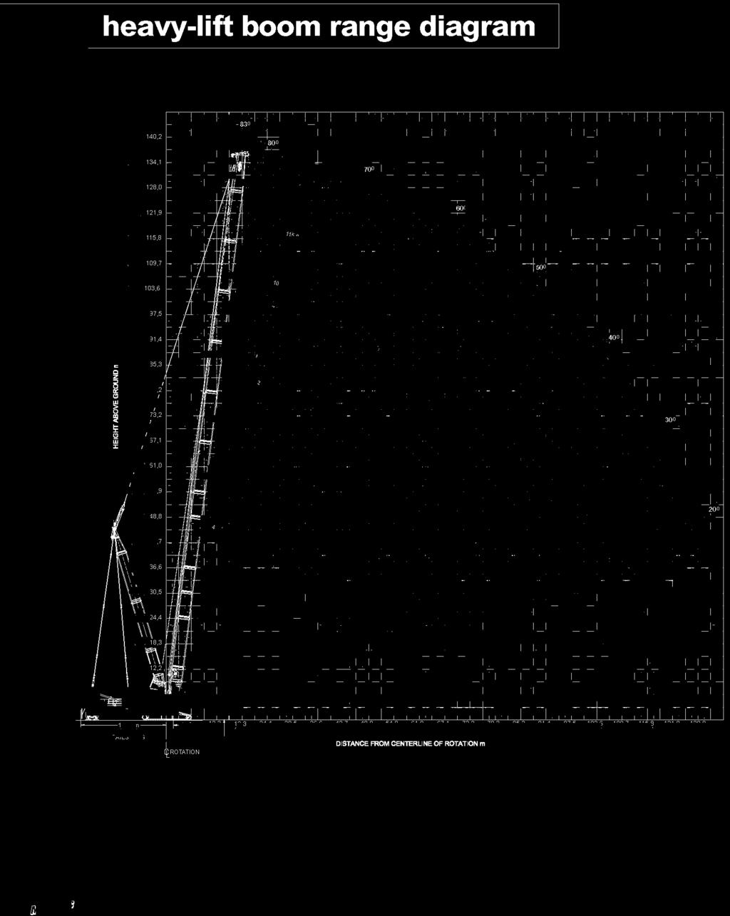
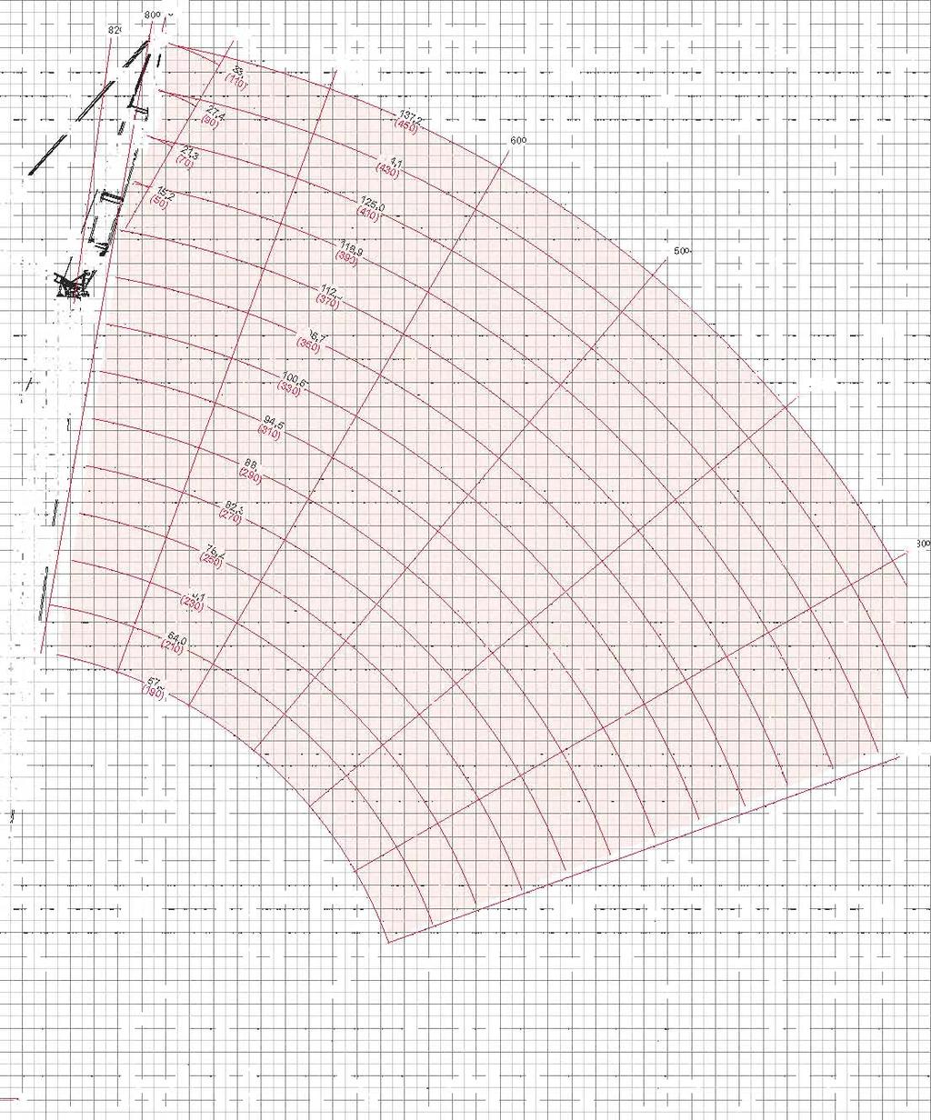
47 heavy-lift load charts 00 MAX-ER No. 55 or No. 55A, with,7m (') No. 5 Mast with m (59 ) position 3 70 kg (9,000 lb) Counterweight 5 50 kg (30,000 lb) Carbody Counterweight kg (0,000 lb) Wheeled Counterweight or anging Counterweight 30 Rating kg (lb) x 000,5 (),7 () 750,0 (53.5) 5,9 () 7, (0) 79, (0) 9, 3, (30) 5, (30) 3,0 (0) 7,0 (3) 750,0 (53.5), (509.),0 (0) 75,7 (53.3), (509.) 570,9 (5.0),0 (50) 9,9 (3.) 7,9 (303.) 55, (.) 05, (9.) (55,0),0 (0) 50, (9.) 99,3 (3.3) 97, (75.) 05, ( 9.) 97, ( 55,0) 3, (9.9) (37.) 0,0 (70) 50, (99.9),0 (93.9), (9.3) 05, ( 9.) 97, ( 55,0) 3, ( 9.9) 9,7 ( 37.) 7, (5.5),0 (0) 373, (09.) 370, (03.3) 37,0 (795.7) 3, (79.) 97, ( 55,0) 3, ( 9.9) 9,7 ( 37.) 7, ( 5.5) 30,0 (0) 9,5 (3.) 9,9 (3.),5 (5.) 5, (.9), (.) 3, ( 9.9) 9,7 ( 37.) 7, ( 5.5) 3,0 () 33, (50.) 39, (5.0) 35, (5.) 3, (50.) 9,7 (97.) 3, ( 9.9) 9,5 (373.7), (5.5),0 (), (37.5) 0,0 (35.) 97, (7.7) 9, (.) 9, (.9) 9,9 (.9) 7, (3.) 5, (53.),0 () 7,5 (359.),9 (35.), (359.3) 3, (35.),3 (3.7) 59, (33.7) 3, (50.) 5,0 () 3,5 (5.7), (3.) 3,7 (3.),7 (30.0) 3,9 (300.) 3, (95.),0 (.5),0 (0) (37.) (3.7), (9.0) 3,9 (.0),3 (.) 7,0 (0) (97.) (05.) (0.) (97.) (9.) 7,0 (0),0 (0) 90,0 9,0 (30),0 (30),0 (30),0 (30) 30,0 (30),7 (75.) (5.) 3,3 (79.3) (57.),3 (3.) (7.9), (7.5) (5.9), (37.) (5.) 5,3 (9.) (75.) 77, (.7) (7.) 0,7 (30.) (5.3) 7, (99.) (.) 3,7 (5.3) 3,9 (.0) MAX-ER Meets ANSI B30.5 Requirements - Capacities do not exceed 75% of static tipping load. NOTICE: This capacity chart is for reference only and must not be used for lifting purposes.
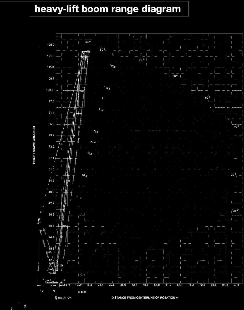
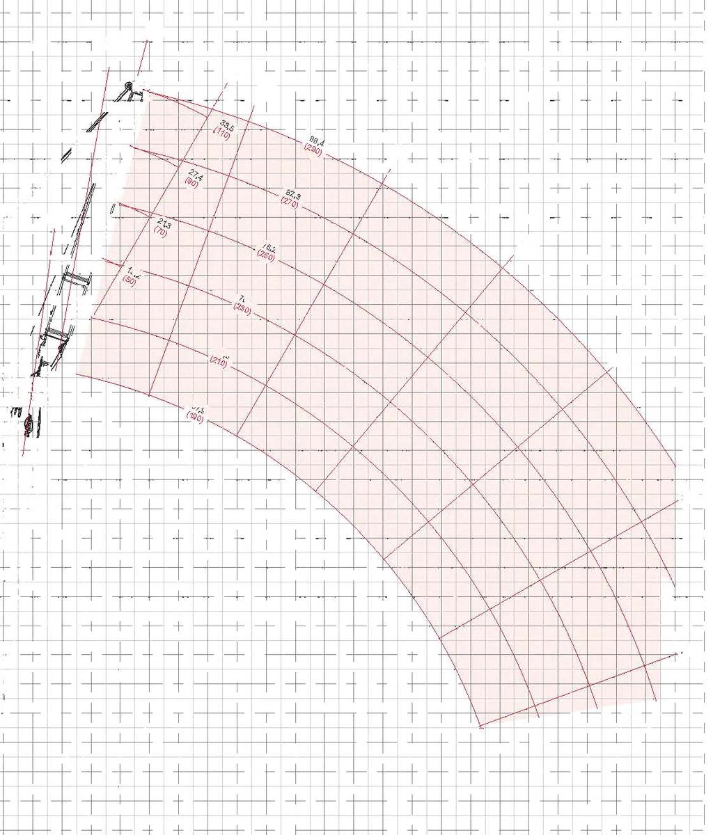
48 heavy-lift boom range diagram 00 MAX-ER No. 55 or No. 55A, with,7m (') No. 5 Mast with m (0 ) position 3 70 kg (9,000 lb) Counterweight 5 50 kg (30,000 lb) Carbody Counterweight kg (0,000 lb) Wheeled Counterweight or anging Counterweight 30 Rating kg (lb) x 000,7 () 5,9 () 7, (0) 79, (0) 9, 3, (30) 5, (30) 3,0 (0),5 () 750,0 (53.5),0 (3) 79, (53.3), (509.),0 (0), (333.), (37.0) 570,9 (5.0),0 (50) 5,7 (.) 53, (59.) 5, (5.) 05, (9.) (55,0),0 (0) 07, (.7) 05,0 (7.) 0, (7.) 39, (.) 97, (55,0) 3, (9.9) (37.) 0,0 (70) 35,7 (753.) 3,9 (77.) 359,5 (70.0) 35,7 (733.) 97, (55,0) 3, (9.9) 9,7 (37.) 7, (5.5),0 (0) 99,3 (.) 99, (.) 95,7 (0.9) 9, (3.) 7, (7.) 3, (9.9) 9,7 (37.) 7, (5.5) 30,0 (0),7 (0.) 3, (50.3) 3, (500.7),3 (9.) 5, (7.) 0,5 (3.) 9,7 (37.) 7, (5.5) 3,0 () 7,3 (3.) 9, (07.) 7,7 (0.3), (00.), (393.3),0 (39.3) 9,5 (373.7), (5.5),0 () 3, (0.0) 9, (3.) 5, (33.3) 53, (33.) 50,5 (35.),7 (3.5), (3.) 5, (53.),0 () 9,9 (5.9),7 (7.3) 30,0 (0.9),9 (7.) 5, (70.3),9 (5.3) 3, (50.) 5,0 () 9,7 (99.7), (3.9), (37.),5 (3.), (30.3),5 (5.3) 0,9 (7.),0 (0) 7,3 (5.) 77, (5.0) 79, (7.) 77,5 (.) 7,0 (59.0) 7,0 (0) (7.) (3.) (.0) (.7) (3.9) MAX-ER 7,0 (0),0 (0) 90,0 9,0 (30),0 (30),0 (30),0 (30) 30,0 (30) 5,5 (.5) (5.) 5, (5.) (93.) 35, (73.) (5.7) 5,3 (9.) (9.) 3,7 (7.5) (59.0), (3.) (.) 55, (.) (9.3) 37, (7.0) (0.),0 (.) (30.7) 9, (.0) Meets ANSI B30.5 Requirements - Capacities do not exceed 75% of static tipping load. NOTICE: This capacity chart is for reference only and must not be used for lifting purposes.

49
50 fixed jib load charts 50 iftcrane Jib Capacities - 00 MAX-ER Jib No. 79A with 5, m (50 ft) Strut on No. 55 or 55A with,7 m ( ft) mast No. 5 3,70 kg (5,000 lb) Crane Counterweight 5,50 kg (30,000 lb) Carbody Counterweight 390,090 kg (0,000 lb) Wheeled Counterweight at m (59 ) Position 30 Rating kg (lb) x 000,7 (),0 (00) 5 Offset 79,3 (0) 9, 3,7 (30),7 (),0 (00) 0 Offset 79,3 (0) 9, 3,7 (30) 3,7 (5) 500,0 (.) 0,0 (70),9 (95.9) 39,7 (55.),5 (57.) (37.3) 90, (9.0) 3, (70.5) 30,0 (0), (0.5),3 (09.),5 (57.) 9,3 (37.3), (37.) 30, (50.), (57.5),0 (5.5), (0.3) 3, (90.3) Jib ength 5, m (50 ft) 3,0 (),0 () 0,0 (00) 7,0 (0),0 (0) 90,0, (503.9) 5,5 (35.), (9.) 59,9 (3.7), (5.) 75,7 (79.) 55,9 (0.) 5, (33.),9 (3.) 3, (95.) 5,7 (.) (.) 9,3 (35.3) 50, (35.5) 9,5 (35.7), (.) 57,3 (9.) (9.),0 (33.), (33.9) 7, (30.7) 79, (70.) 59,3 (.3) (0.), (.) 5, (330.9) 5, (9.7),3 (3.5) 7,3 (50.5),0 (.5) 5, (33.0), (.5) 5, (.5), (0.3) 53, (33.), (39.),9 (77.9) 59, (3.9) (9.) 3, (90.3) 30,9 (.) 9,3 (35.3) 0,9 (73.) 0,3 (.7) (3.),0 (30) (5.5),0 (370) (.0),0 (00),7 (),0 (00) 79,3 (0) 9, 3,7 (30),7 (),0 (00) 79,3 (0) 9, 3,7 (30) MAX-ER Jib ength,3 m (70 ft) 3,7 (5) 0,0 (70) 30,0 (0) 3,0 (),0 () 0,0 (00) 7,0 (0),0 (0) 90,0,0 (30),0 (370),0 (00) 00, (77.),0 (3.) 7, (50.9) 57,0 (337.5),9 (3.3) 30,0 (79.) 3,0 (.), (95.),7 (37.) 9,0 (55.7),3 (7.) (.),5 (.),5 (.) 55,3 (335.) 3, (5.) 5,7 (.) 5,5 (3.0) (9.7) 7,9 (379.) 7,9 (37.) 5,0 (3.0), (37.7), (7.) 0,5 (7.3) (.) (57.0) 30, (.9) 9, (.0) 5,5 (7.), (3.) 0,0 (7.7) 59, (7.) (.) (.3),7 (3.7) 7, (577.), (3.5) 03, (.) 5,5 (337.0) 3,9 (507.5),7 (3.) 3,0 (35.), (0.0) 0,7 (55.7) 0,7 (55.7) 5,3 (3.) 5,9 (9.) 7, (7.) 0, (.7) 5,3 (39.) 5,3 (39.) 55,3 (335.5),9 (3.0), (.5) 3, (3.5) (5.3) 7,0 (5.0) 7,0 (5.0) 7,0 (5.0), (3.5), (7.0),3 (30.) (.3) (5.3) Meets ANSI B30.5 Requirements - Capacities do not exceed 75% of static tipping load. NOTICE: This capacity chart is for reference only and must not be used for lifting purposes.
51 fixed jib load charts iftcrane Jib Capacities - 00 MAX-ER Jib No. 79A with 5, m (50 ft) Strut on No. 55 or 55A with,7 m ( ft) mast No. 5 3,70 kg (5,000 lb) Crane Counterweight 5,50 kg (30,000 lb) Carbody Counterweight 390,090 kg (0,000 lb) Wheeled Counterweight at m (59 ) Position 30 Rating kg (lb) x 000 5,7 (),0 (00) 5 Offset 79,3 (0) 9, 3,7 (30),7 (),0 (00) 0 Offset 79,3 (0) 9, 3,7 (30) 3,7 (5) 0,0 (70) 3, (755.) 9,5 (3.) 30,0 (0), (.9),0 (.3), (0.) 3,5 (9.7) 99,7 (0.0) 0, (53.9) 3, (.) 7, (39.9) (30.5) Jib ength 7, m (90 ft) 3,0 (),0 () 0,0 (00) 7,0 (0),0 (0) 90,0, (50.),3 (35.0), (35.5) 3, (9.7), (3.3) 9,7 (5.) 5,0 (.), (0.) 55,7 (33.), (5.), (5.0),3 (9.) (3.) 3,5 (9.7) 3,5 (9.7), (3.5),7 (77.5), (3.) (.5) 99,7 (0.0) 99,7 (0.0) 99,7 (0.0) 0,3 (7.) 0,0 (.) (.) 9,9 (39.) 7,0 (30.3) 3,0 (.) 0,5 (3.7) 3,7 (35.), (.) 7, (.7) 7, (39.9) 59, (3.3), (5.),0 (9.0),0 (3.9) (7.) 3, (30.5) 3, (30.5) 3, (5.),9 (.3),0 (3.) (.),3 (30.0),3 (30.0) 3,7 (.), (77.7),9 (3.) (3.),0 (30) (3.0) (.) (7.3),0 (370), (3.), (39.) 0,3 (.5),0 (00) (5.0),7 (),0 (00) 79,3 (0) 9, 3,7 (30),7 (),0 (00) 79,3 (0) 9, 3,7 (30) Jib ength 33,5 m ( ft) 3,7 (5) 0,0 (70) 30,0 (0) 3,0 (),0 () 0,0 (00) 7,0 (0),0 (0) 90,0,0 (30),0 (370),0 (00) (703.3),7 (59.7), (.0) 3,0 (350.9) 3, (3.9) 7,5 (.) 5,7 (5.) 5,7 (9.0), (39.7),3 (59.),3 (.) 0,7 (.0) (.) 5, (39.3) 5, (39.3) 55,7 (337.),7 (7.),7 (.), (35.) (.) (7.) 9,7 (.) 9,7 (.), (39.) 3,3 (7.9) 3, (3.9) (.) (9.) 0,0 (.) 5,7 (9.0) 5,7 (9.0) 5,7 (9.0) 0,9 (73.5) 0, (9.5) (.) (7.7), (.) (.3) 0,0 0,5 (3.) (,9) 9, 95,7 (35.) (00,5),3 (3.) 7,7 (5.9) 53, (33,9), (.9) 9, (9.3) 3,0 (3.) (33.) 55,9 (33.) 5,3 (33.) 7,9 (5.) 9, (9.5) 7, (3.) (.5), (.3), (.3) 5,0 (7.7), (.) 5, (39.3) (.0) (7.) (0.) 9,3 (0.) 9, (0.), (7.3) 3,0 (3.) (.) (7.) 3,5 (9.) MAX-ER Meets ANSI B30.5 Requirements - Capacities do not exceed 75% of static tipping load. NOTICE: This capacity chart is for reference only and must not be used for lifting purposes.

52
53 luffing jib load charts iftcrane uffing Jib Capacities - 00 MAX-ER uffing Jib No. 79A on No. 55 or No. 55A With,7m (') Mast No kg (9,000 lb) Counterweight 5 50 kg (30,000 lb) Carbody Counterweight kg (0,000 lb) Wheeled Counterweight or anging Counterweight 30 Rating kg (lb) x Angle uffing Jib ength 7, m (90 ft), (55),0 (0) 0,0 (70),0 (0),0 (90) 30,0 (0) 3,0 (),0 (),0 (), () 33, (737.7) 37,0 (77.0) 35,9 (.7),5 (0.7),0 (50.9) 9,5 (.7),0 (00) (3.0) 7,9 (5.0) 3,7 (530.) 7, (7.5) 99,5 (33.3) 79, (0) (( 7 9,0 (09.5) 75, (3.), (35.5) 50, (37.), (7.) 9, (33.5) 39,3 (305.7) 3, (.), (.), (.) uffing Jib ength 5,7 m (50 ft), (55),0 (0) 0,0 (70),0 (0),0 (90) 30,0 (0) 3,0 (),0 (),0 (), () 3, (90.) 5, (59.0) 95,0 (.5), (35.),3 (7.5) 3,7 (.),0 (00) (390.) 73,3 (37.) 59,0 (3.) 3,0 (95.) 5,3 (9.) 99, (5.7) 79, (0) 5, (7.0) 7,3 (5.5) 3,3 (.9) 9, (95.) 7,9 (7.5) 9, 0,5 (.0) 95,0 (07.) 5,0 (5.) 7,9 (.9),5 (.) 5,0 () 5,0 () 73,5,5 (3.) (35.7), (),0 (00) 79, (0) 9,, (),0 (00) 79, (0) 9,,0 (95) (79.7),0 (95) uffing Jib ength 70, m (30 ft) 3,0 (5) 3,0 (),0 () 5,0 (),0 (0) 7,0 (0) 90,0 9,0 (30),0 (30) 7, (73.),0 (5.3),0 (3.3) 77,9 (3.9) 59, (33.0) 3,3 (7.9) 9,3 (5.) 9, (95.3) 7,0 (53.9) 55, (.) 77, (70.) 73,7 (.5) 7, (7.9) 5,7 (.) 3, (9.9) 3, (3.) 59, (3.) 55, (.) 5, (97.9) 3, (79.0) 3,0 (7.) uffing Jib ength 9,5 m (3 ft) 3,0 (5) 3,0 (),0 () 5,0 (),0 (0) 7,0 (0) 90,0 9,0 (30),0 (30), (50.) 53, (.) 3, (3.0), (55.3) (33.3),9 (.) 0, (3.) 53,0 (5.5) 39,3 (.3) 7,0 (57.) (3.9), (5.) 5, (99.) 39,9 (7.) 33,7 (73.) 5,5 (5.) (3.3),5 (5.) (.) 3,3 (79.) 3,9 (9.), (5.), (5.5) (35.) 3, (.) (9.) MAX-ER Meets ANSI B30.5 Requirements - Capacities do not exceed 75% of static tipping load. NOTICE: This capacity chart is for reference only and must not be used for lifting purposes.
54 luffing jib load charts 5 iftcrane uffing Jib Capacities - 00 MAX-ER uffing Jib No. 79A on No. 55 or No. 55A With,7m (') Mast No kg (9,000 lb) Counterweight 5 50 kg (30,000 lb) Carbody Counterweight kg (0,000 lb) Wheeled Counterweight or anging Counterweight 30 Rating kg (lb) x Angle, (),0 (00) 79, (0) 9,, (),0 (00) 79, (0) 9, uffing Jib ength 7, m (90 ft),0 (75),0 (0),0 (90) 30,0 (0) 3,0 () 3,0 (),0 (),0 () 5,0 () (700.0) 309, (50.5) 5, (539.5) 5,0 (5.) 77,0 (33.5) 95,3 (3.) 7,5 (5.5) 5, (5.9) 0,5 (3.3) (( 7 9,5 (0.9) 77, (395.5) 9, (3.0), (33.7) (39.) 3,7 (3.) 3,3 (30.0), (.) uffing Jib ength 5,7 m (50 ft),0 (75),0 (0),0 (90) 30,0 (0) 3,0 () 3,0 (),0 (),0 () 5,0 () (5.3) 5,5 (.9) 9, (.9) 9,5 (3.5),0 (0.) 97,7 (9.) 9,5 (.) 7,9 (390.) 57, (3.5) 30, (79.),9 (9.) 30,9 (7.0) 9,5 (0.3) 5,9 (9.7) 9,9 (0.3) 97, (3.0), (9.5) 7, (70.) 0,0 (00) 0,0 (00) 3, (3.) 70, (53.9), (),0 (00) 79, (0) 9,, (),0 (00) 79, (0) 9, 3,0 (30) 3,0 (30) MAX-ER uffing Jib ength 70, m (30 ft),0 (50) 50,0 (70) 0,0 (00) 70,0 (30) 7,0 (0),0 (90) 9,0 (30),0 (350),0 (370),0 (.),3 (.), (75.),5 (37.5), (95.5) 5,0 (3.0) 0,5 (.) 5, (5.5) 5,9 (5.) 53, (5.) 79,0 (7.7) 7,3 (.7),5 (.) 55,9 (3.), (5.7) (5.7),9 (3.) 5,7 (9.0), (.7),0 (.9) 37,7 uffing Jib ength 9,5 m (3 ft),0 (50) 50,0 (70) 0,0 (00) 70,0 (30) 7,0 (0),0 (90) 9,0 (30),0 (350),0 (370), (3.) 5,9 (.) 39,5 (.9) 30,7 (.9) (.) (30.) (.) 53, (.7), (9.) 3, (9.3) 3, (50.3), (3.) (.0) 5, (.0) 39,3 (.5) 3,0 (.) 3, (5.) 7, (3.0) (3.) 37,0 (.) 3,0 (7.9) 30,9 (7.),7 (53.),7 (3.9) (5.7),7 Meets ANSI B30.5 Requirements - Capacities do not exceed 75% of static tipping load. NOTICE: This capacity chart is for reference only and must not be used for lifting purposes.
55 luffing jib load charts iftcrane uffing Jib Capacities - 00 MAX-ER uffing Jib No. 79A on No. 55 or No. 55A With,7m (') Mast No kg (9,000 lb) Counterweight 5 50 kg (30,000 lb) Carbody Counterweight kg (0,000 lb) Wheeled Counterweight or anging Counterweight 30 Rating kg (lb) x Angle 55, (),0 (00) 79, (0) 9,, (),0 (00) 79, (0) 9, uffing Jib ength 7, m (90 ft) 30,0 (0) 3,0 () 3,0 (30),0 (),0 (50) 50,0 (70) 5,0 (90),0 (),0 (0) (503.0) 9, (.0) 9,7 (.), (37.7) ( 7.0) 90, (.), (3.9) 57,0 (( 7 (30.7), (3.0) 30, (99.),3 (3.7) uffing Jib ength 5,7 m (50 ft) 30,0 (0) 3,0 () 3,0 (30),0 (),0 (50) 50,0 (70) 5,0 (90),0 (),0 (0) (39.0) 50,7 (3.),0 (5.9) 9, (0.) (3.5) 35,7 (.), (3.3), (7.) (9.),7 (39.7), (.) 99,3 9,7 (.) 70,0 (30) 70,0 (30) 97, 9,5 (5.0) (03.), (),0 (00) 79, (0) 9,, (),0 (00) 79, (0) 9,,0 (),0 () uffing Jib ength 70, m (30 ft) 5,0 () 0,0 (00) 70,0 (30) 7,0 (0),0 (90) 9,0 (30),0 (350),0 (370),0 (0) 0,3 (7.7) 77, (70.) 3,0 (3.) 7,9 (.5) 7,3 (9.0) 70, (9.7) 5, (.9) 73, (.) 73, (.) 3, (39.) 5, (.9) 0,3 (33.) 5, (.3) 5,7 (.0) uffing Jib ength 9,5 m (3 ft) 5,0 () 0,0 (00) 70,0 (30) 7,0 (0),0 (90) 9,0 (30),0 (350),0 (370),0 (0) 39, (.5) 9, (3.), (5.3) (30.0), (.) 3,5 (93.0) 33, (7.) 5, (53.) (3.7), (7.3) 3, (7.), (59.) (3.) 5, (33.9) 3,3 (75.) 30, (.9) (9.),7 (0.), (9.) MAX-ER Meets ANSI B30.5 Requirements - Capacities do not exceed 75% of static tipping load. NOTICE: This capacity chart is for reference only and must not be used for lifting purposes.
56 Manitowoc Crane CARE 5 Crane CARE is Manitowoc s comprehensive service and support program. It includes classroom and on-site training, prompt parts availability, expert field service, technical support and documentation for every one of the more than 7,000 Manitowoc cranes currently in use throughout the world. That s commitment you won t find anywhere else. That s Crane CARE. Service Training Manitowoc specialists work with you in our training center and in the field to make sure you know how to get maximum performance, reliability, and life from your cranes. Manitowoc Cranes Technical Training Center provides valuable multi-level training, which is available for all models and attachments, in the following format: Basic Provides technicians with the basic skills required in our evel I and II classes covering hydraulic and electrical theory and schematics, pump, motor, control, and MI operation, and the use of meters and gauges. evel This model-specific class covers theory and offers hands-on training and trouble shooting or all crane systems. evel This model-specific class provides in depth coverage of all crane systems and components, and advanced troubleshooting of simulated faults. (Requires evel.) evel 3 / Master Covering all EPIC models and the 0W, this class stresses high level system knowledge and trouble shooting of simulated faults. Requires evel.) Parts Availability Genuine Manitowoc replacement parts are accessible through your distributor hours a day, 7 days a week, 35 days a year. Service Interval Kits Provides all the parts required by Manitowoc s Preventative Maintenance Checklist. ydraulic Filter Kit Consists of the following: Filter Element - ydraulic in Tank () Cummins Model QSZ5-C00 Diesel Service Interval Kits 00 our Kit Consists of the following: Engine Filter Oil () Filter Water () Filter Fuel (),000 our Kit Consists of the following: Engine Filter Air Cleaner - Primary () Filter Oil () Filter Water () Filter Fuel () ydraulic Filter Element - ydraulic in Tank () Element - yraulic Tank Breather (),000 our Kit Consists of the following: Engine Filter, Air Cleaner - Primary () Filter, Air Cleaner - Safety () Filter, Oil () Filter, Water () Filter, Fuel () Ether, (Bottle) () Sensor, Coolant evel () Belt, Fan () Belt, Alternator (set of two) () Filter, Element () ydraulic Filter Element - No substitutions allowed Filter - ydraulic In-Tank Suction () Kit, Engine Coolant Additive (SCA) Test () Kit, Seal (for hydraulic in tank filter) () Seal, Radial (for air cleaner) () ydraulic Test Kit Protect your investment by demanding Genuine Manitowoc Parts Service Kits. The ydraulic Service Kit consist of the following: All hydraulic fittings to access all pressures and flows ydraulic flow meters and pressure gauges to record hydraulic data. Electrical Break out harnesses to access voltages on all electrical circuits on all machines. Fluke Digital volt ohm meter, as used in all Manitowoc service literature. ydraulic Test Kit with case The above kit plus a custom heavy-duty carrying case. U.S. Standard Tools Kit All standard tools needed to properly maintain and service your crane. (Does not include torque wrench.)

57 Manitowoc Crane CARE Field Service Factory-trained service experts are always ready to help maintain your crane s peak performance. For a worldwide listing of dealer locations, please consult our website at: Technical Support Manitowoc s dealer network and factory personnel are available hours a day, 7 days a week, 35 days a year to answer your technical questions and more, with the help of computerized programs that simplify crane selection, lift planning, and ground-bearing calculations. For a worldwide listing of dealer locations, please consult our website at: Crane Safety Video Inspection/Repair Video Crane CARE Package Manitowoc has assembled all of the available literature, CD s, and videos listed above plus several Manitowoc premiums into one complete CraneCARE Package. 57 Technical Documentation Manitowoc has the industry s most extensive documentation, and the easiest to understand, available in major languages and formats that include print, disk, and videotape. Additional copies available through your Authorized Manitowoc Distributor. Crane Operator s Manual Crane Parts Manual Crane Capacity Manual Crane Vendor Manual Service Manual (EPIC) uffing Jib Operator s/parts Manual Capacity Chart Manual - Attachments CD rom versions of the Operator s and Parts Manuals are shipped with each crane. Also available are the following CDs: Crane CARE Owner CD Ground Bearing Pressure Estimator CD Crane Selection and Planning Software (CompuCRANE ) EPIC Crane ibrary CD consisting of capacity charts, range diagrams, wire rope specifications, travel specifications, crane weights, counterweight arrangements, luffing jib raising procedures, operating range diagrams, drum and lagging charts, boom rigging drawings, jib rigging drawings, outline dimensions, and wind condition charts. Available from your Authorized Manitowoc Cranes Distributor, these VS videos are available in NTSC, PA and SECAM formats. Your Capacity Chart Video Respect the imits Video


58 Americas USA Manitowoc Crane CARE 0 S. 30th Street, Manitowoc, WI 50 USA Tel: + 90 Fax: Manitowoc Crane CARE 55 Buchanan Trail East, Shady Grove, PA 75 USA Tel: Fax: Manitowoc Crane CARE 3 West Sardis Road Bauxite, AR 70 USA Tel: Fax: Brazil Manitowoc Crane CARE Edificio: Itaim Office Tower Rua Gomes de Carvalho, 5 - andar cj 05 / 0 Vila Olimpia - SP - Cep: Brasil Tel: Fax: Mexico Manitowoc Crane CARE Miravalle Center, piso PB, Suite Calz San Pedro 50 Nte. Monterrey, Nuevo eon, Mexico Tel: Fax: Europe - Middle East - Africa United Kingdom Manitowoc Crane CARE Akeler ouse, Emperor Way Doxford International Business Park Sunderland, England SR3 3XR Tel: Fax: France Manitowoc Crane CARE chaussee jules-cesar, 9553 Cergy Pontoise, France Tel: Fax: Manitowoc Crane CARE Z.A. es Pivolles - 5 rue De Catalogne, 953 Decines Charpieu Cedex, France Tel: Fax: Germany Manitowoc Crane CARE Industriegelände West 39 Wilhelmshaven Postfach 53, Germany Tel: Fax: Manitowoc Crane CARE Carl-everkus-Str. 07 angenfeld, Germany Tel: Fax: Italy Manitowoc Crane CARE Via delle Fabbriche, 0 Niella Tanaro, Italy Tel: Fax: Netherlands Manitowoc Crane CARE Veilingkade 5 5 C Breda Tel: Fax: Portugal Manitowoc Crane CARE Rua da Serra (EN 5/) Apartado Alfena, Portugal Tel: Fax: United Arab Emirates (UAE) Manitowoc Crane CARE P.O. Box 753 Villa 35, Road 3D Al Quoz, Dubai Tel: Fax: Asia - Pacific Singapore Manitowoc Crane CARE Kwong Min Road Singapore, 707 Singapore Tel: + 5 Fax: (Sales/Admin) + 5 (Parts/Service) China Manitowoc Crane CARE No. 55 East Zhen Bei Road South District Zhangjiagang Economic Development Zone Zhangiagang, Jiangsu 5 P R China Tel: Fax: Manitowoc Crane CARE RM. F. F Cross egion Plaza 99 ingling Road Shanghai, 00030, PR China Tel: Fax: Manitowoc Crane CARE RM -5, #933 Zhongshan West Road ongqiao Silver Tower Shanghai 0005, P R China Tel: Fax: Australia Manitowoc Crane CARE / Disney Avenue, East Keilor VIC 3033 Australia Tel: Fax: Manitowoc Crane CARE Magowar Road Girraween NSW 5 Australia Tel: Fax: Korea Manitowoc Crane CARE RM 30 Gugu Building 5- Samsung-Dong, Kangnam-Ku Seoul 35-7 Korea Tel: Fax: Phillipines Manitowoc Crane CARE G/F Southwest Centre Building Corner Makiling Street Southwest Superhighway, Palanan, Makati City 35 Phillipines Tel: Fax: PRODUCT IMPROVEMENTS MAY CANGE SPECIFICATIONS 00 MANITOWOC PG-US-E
Manitowoc Product Guide. Features. View thousands of Crane Specifications on FreeCraneSpecs.com
 Manitowoc 000 Product Guide Features 750 t (5 USt) capacity No. 55A boom with MAX-ER 00 t (0 USt) capacity No. 55 boom 9 09 mton-m (5,505 ft-kips) maximum load moment with MAX-ER 97,5 m (30 ft) No. 55
Manitowoc Product Guide. Features. 600 m-ton (660 ton) capacity No. 55 Boom. 750 m-ton (825 ton) Capacity No. 55A Boom with MAX-ER
 capacity No. 55 Boom. 750 m-ton (825 ton) Capacity No. 55A Boom with MAX-ER") Manitowoc 000 Product Guide Features 00 m-ton (0 ton) capacity No. 55 750 m-ton (5 ton) Capacity No. 55A with MAX-ER 9 09 mton-m (5,505 ft-kips) Maximum oad Moment withmax-er 97,5 m (30 ) No. 55 9,3 m
Manitowoc 000 Product Guide Features 00 m-ton (0 ton) capacity No. 55 750 m-ton (5 ton) Capacity No. 55A with MAX-ER 9 09 mton-m (5,505 ft-kips) Maximum oad Moment withmax-er 97,5 m (30 ) No. 55 9,3 m
model 555 product guide features contents 136 mton (150 ton) Capacity Specifications mton-m (3,900 ft-kips) Maximum Load Moment
 Capacity Specifications mton-m (3,900 ft-kips) Maximum Load Moment") product guide features 36 mton (50 ton) Capacity 539 mton-m (3,900 ft-kips) Maximum oad Moment 76, m (50') eavy-ift 85,3 m (80') Fixed Jib on eavy-ift 00,6 m (330') uffing Jib 53 kw (340 P) engine 8,9
product guide features 36 mton (50 ton) Capacity 539 mton-m (3,900 ft-kips) Maximum oad Moment 76, m (50') eavy-ift 85,3 m (80') Fixed Jib on eavy-ift 00,6 m (330') uffing Jib 53 kw (340 P) engine 8,9
model PROVISIONAL product guide features contents 200 mton (220 ton) capacity 865 m-ton (6,267 ft-kips) Maximum Load Moment
 capacity 865 m-ton (6,267 ft-kips) Maximum Load Moment") features 200 mton (220 ton) capacity 865 m-ton (6,267 ft-kips) Maximum Load Moment 89 m (292') Heavy-Lift Boom 98,4 m (323') Fixed Jib on Heavy-Lift Boom 113,8 m (373') Luffing Jib on Heavy-Lift Boom 253
features 200 mton (220 ton) capacity 865 m-ton (6,267 ft-kips) Maximum Load Moment 89 m (292') Heavy-Lift Boom 98,4 m (323') Fixed Jib on Heavy-Lift Boom 113,8 m (373') Luffing Jib on Heavy-Lift Boom 253
model 999 product guide contents features 250 mton (275 ton) capacity mton-m (8,268 ft-kips) Maximum Load Moment 88,4 m (290') Heavy-Lift Boom
 capacity mton-m (8,268 ft-kips) Maximum Load Moment 88,4 m (290') Heavy-Lift Boom") features 50 mton (75 ton) capacity 5 mton-m (8,68 ft-kips) Maximum oad Moment 88, m (90') eavy-ift 0,6 m (0') ong-reach 00,6 m (0') Fixed Jib on eavy-ift 5,8 m (80') Fixed Jib on ong-reach 90 kw (75 P)
features 50 mton (75 ton) capacity 5 mton-m (8,68 ft-kips) Maximum oad Moment 88, m (90') eavy-ift 0,6 m (0') ong-reach 00,6 m (0') Fixed Jib on eavy-ift 5,8 m (80') Fixed Jib on ong-reach 90 kw (75 P)
data model 2250 product guide contents features 272 mton (300 ton) capacity mton-m (12,294 ft-kips) Maximum Load Moment
 capacity mton-m (12,294 ft-kips) Maximum Load Moment") data features 272 mton (300 ton) capacity 700 mton-m (2,29 ft-kips) Maximum oad Moment 9, m (300') eavy-ift 00,6 m (330') ong-reach 2,8 m (370') Fixed Jib on eavy-ift 8,9 m (390') Fixed Jib on ong-reach
data features 272 mton (300 ton) capacity 700 mton-m (2,29 ft-kips) Maximum oad Moment 9, m (300') eavy-ift 00,6 m (330') ong-reach 2,8 m (370') Fixed Jib on eavy-ift 8,9 m (390') Fixed Jib on ong-reach
Manitowoc 999. Product Guide. Features. 250 t (275 USt) capacity m-ton (8,268 ft-kips) maximum load moment. 88,4 m (290 ft) heavy-lift boom
 capacity m-ton (8,268 ft-kips) maximum load moment. 88,4 m (290 ft) heavy-lift boom") Manitowoc 999 Product Guide Features 250 t (275 USt) capacity 1 115 m-ton (8,268 ft-kips) maximum load moment 88,4 m (290 ft) heavy-lift boom 100,6 m (330 ft) fixed jib on heavy-lift boom 128,0 m (420
Manitowoc 999 Product Guide Features 250 t (275 USt) capacity 1 115 m-ton (8,268 ft-kips) maximum load moment 88,4 m (290 ft) heavy-lift boom 100,6 m (330 ft) fixed jib on heavy-lift boom 128,0 m (420
data model 222 product guide contents features 91 mton (100 ton) capacity Specifications 2 Outline Dimensions 6 Transport Data 12
 capacity Specifications 2 Outline Dimensions 6 Transport Data 12") data features 9 mton (00 ton) capacity 07 mton-m (,4 ft-kips) Maximum oad Moment 6,0 m (00') eavy-ift 76, m (50') Fixed Jib on eavy-ift 80,8 m (65') uffing Jib on eavy-ift 96,0 m (5') Fixed Jib on uffing
data features 9 mton (00 ton) capacity 07 mton-m (,4 ft-kips) Maximum oad Moment 6,0 m (00') eavy-ift 76, m (50') Fixed Jib on eavy-ift 80,8 m (65') uffing Jib on eavy-ift 96,0 m (5') Fixed Jib on uffing
model 111 product guide
 model product guide features 73 mton (80 ton) capacity 29 mton-m (2,00 ft-kips) Maximum oad Moment 57,9 m (90') eavy-ift Boom 70,m (230') Fixed Jib on eavy-ift Boom 53 kw (205 P) engine EPIC controls 82
model 5500 product guide contents 55 ton Lift Capacity Maximum Load Moment 160' Heavy-Duty Boom on Heavy-Duty Boom 213 HP engine 338 fpm line speed
 55 ton ift Capacity ft-kips,28 Maximum oad Moment product guide ' eavy-duty Fixed Jib ' on eavy-duty 23 P engine 338 fpm line speed 35,000 lb Maximum ine Pull lb Material Rehandling 5,0 Clamshell capacity
230 Ton (209-mton) liftcrane 32,000 lb. (14,515 Kg) Clamshell 20,000 lb. (9,072 Kg) Dragline
 liftcrane 32,000 lb. (14,515 Kg) Clamshell 20,000 lb. (9,072 Kg) Dragline") 3 Ton (9-mton) liftcrane 3, lb. (4,55 Kg) Clamshell, lb. (9,7 Kg) Dragline 888 OUTLINE DIMENSIONS 43'7/t' (3.3 m) - 9'4 /t' (8.95 m) Tailswing-++.j t---9'/t' (8.9 m) --r-+--j--h--- 35'9/t' (.9 m) ------
3 Ton (9-mton) liftcrane 3, lb. (4,55 Kg) Clamshell, lb. (9,7 Kg) Dragline 888 OUTLINE DIMENSIONS 43'7/t' (3.3 m) - 9'4 /t' (8.95 m) Tailswing-++.j t---9'/t' (8.9 m) --r-+--j--h--- 35'9/t' (.9 m) ------
model PROVISIONAL product guide features contents 200 mton (220 ton) capacity 865 m-ton (6,267 ft-kips) Maximum Load Moment
 capacity 865 m-ton (6,267 ft-kips) Maximum Load Moment") model 4000 PROVISIONAL features 200 mton (220 ton) capacity 865 m-ton (6,267 ft-kips) Maximum Load Moment 89 m (292') Heavy-Lift Boom 98,4 m (323') Fixed Jib on Heavy-Lift Boom 3,8 m (373') Luffing Jib
model 4000 PROVISIONAL features 200 mton (220 ton) capacity 865 m-ton (6,267 ft-kips) Maximum Load Moment 89 m (292') Heavy-Lift Boom 98,4 m (323') Fixed Jib on Heavy-Lift Boom 3,8 m (373') Luffing Jib
Technical Data. Specifications & Capacities. Telescopic Crawler Crane (supersedes 5704)-1015-S Ton (100 metric ton)
-1015-S Ton (100 metric ton)") 1 Technical Data Specifications & Capacities Telescopic Crawler Crane 110 Ton (100 metric ton) CAUTION: This material is supplied for reference use only. Operator must refer to in-cab Crane Rating Manual
1 Technical Data Specifications & Capacities Telescopic Crawler Crane 110 Ton (100 metric ton) CAUTION: This material is supplied for reference use only. Operator must refer to in-cab Crane Rating Manual
HYDRAULIC CRAWLER CRANE
 HYDRAULIC CRAWLER CRANE consolidatedcrane.com Houston, TX 713.641.3330 Max. Lift Capacity: 500,000 lbs Max. Length: 300 ft Max. + Jib Length: 250 ft + 100 ft SPECIFICATIONS FOR CK2500-II CRAWLER CRANE
HYDRAULIC CRAWLER CRANE CK2500
 HYDRAULIC CRAWLER CRANE CK2500 WITH OPTIONAL JIB Max. Lifting Capacity: 250 US Tons Max. Boom Length: 300 ft Max. Boom + Jib Length: 250 ft + 100 ft SPECIFICATIONS FOR CK2500 CRAWLER CRANE The Kobelco
model product guide features contents 110 t (120 USt) Lift Capacity 397 mton-m (2,880 ft-kips) Maximum Load Moment
 Lift Capacity 397 mton-m (2,880 ft-kips) Maximum Load Moment") features 0 t (0 USt) ift Capacity 397 mton-m (,880 ft-kips) Maximum oad Moment 70, m (30 ft) eavy-ift 8,3 m (70 ft) Fixed Jib on eavy-ift 94,5 m (30 ft) uffing Jib on eavy-ift 47 kw (33 P) engine 63 mpm
features 0 t (0 USt) ift Capacity 397 mton-m (,880 ft-kips) Maximum oad Moment 70, m (30 ft) eavy-ift 8,3 m (70 ft) Fixed Jib on eavy-ift 94,5 m (30 ft) uffing Jib on eavy-ift 47 kw (33 P) engine 63 mpm
product 314 mton-m (2,270 ft-kips)
") model 0000 features 90 t (00 USt) ift Capacity product 34 mton-m (,70 ft-kips) guide Maximum oad Moment 6 m (00 ft) eavy-ift 76, m (50 ft) Fixed Jib on eavy-ift 80,8 m (65 ft) uffing Jib on eavy-ift 47
model 0000 features 90 t (00 USt) ift Capacity product 34 mton-m (,70 ft-kips) guide Maximum oad Moment 6 m (00 ft) eavy-ift 76, m (50 ft) Fixed Jib on eavy-ift 80,8 m (65 ft) uffing Jib on eavy-ift 47
4600 SERIES 3 RINGER SERIES 2. Manitowoc Cranes, Inc. Manitowoc, Wisconsin U.S.A.
 Liftcrane Capacities No. 35 thru 1 Degree Static Machine LIFTING CAPACITIES: Lifting capacities are for a RINGER when operating on a barge. Machine shall be positively secured to prevent shifting. Lifting
Technical Data. Specifications & Capacities. Telescopic Crawler Crane S5. 50 Ton (51mt Export Machine)
") 1 5646-0314-S5 Technical Data Specifications & Capacities Telescopic Crawler Crane Ton (51mt Export Machine) CAUTION: This material is supplied for reference use only. Operator must refer to in-cab Crane
1 5646-0314-S5 Technical Data Specifications & Capacities Telescopic Crawler Crane Ton (51mt Export Machine) CAUTION: This material is supplied for reference use only. Operator must refer to in-cab Crane
Technical Data. Specifications & Capacities. HSL Crawler Crane (supersedes 5775)-0917-T Ton (117.9 metric ton)
-0917-T Ton (117.9 metric ton)") 1 Technical Data Specifications & Capacities S Crawler Crane 130 Ton (117.9 metric ton) CAUTION: This material is supplied for reference use only. Operator must refer to in-cab Crane Rating Manual and
1 Technical Data Specifications & Capacities S Crawler Crane 130 Ton (117.9 metric ton) CAUTION: This material is supplied for reference use only. Operator must refer to in-cab Crane Rating Manual and
Specifications Hydraulic Lattice Boom Crawler Crane LS-138H. 75-Ton (68 metric ton) General dimensions Feet meters. General dimensions Feet meters
 General dimensions Feet meters. General dimensions Feet meters") Specifications Hydraulic Lattice Boom Crawler Crane LS-138H 75-Ton (68 metric ton) General dimensions Feet meters General dimensions Feet meters Basic boom length 40' 0" 12.20 Overall width side frames
Specifications Hydraulic Lattice Boom Crawler Crane LS-138H 75-Ton (68 metric ton) General dimensions Feet meters General dimensions Feet meters Basic boom length 40' 0" 12.20 Overall width side frames
LINK-BELT MODEL 218HSL TON CAPACITY
 TRANSPORTATION SPECS - Crawler Cranes INK-BET MODE 218S - 110 TON CAPACITY COMPONENT EIGTS BS. KGS. Complete Crane c/w 40, full Cwt and Block 190,058 86,210 BOOM 60 (1.52m) X 50 (1.72m) Min 40 to Max 230
Technical Data. Specifications & Capacities. Telescopic Crawler Crane (supersedes 5623)-1114-R8. 75 Ton (70 metric ton)
-1114-R8. 75 Ton (70 metric ton)") 1 5706 (supersedes 5623)-1114-R8 Technical Data Specifications & Capacities Telescopic Crawler Crane Ton (70 metric ton) CAUTION: This material is supplied for reference use only. Operator must refer to
1 5706 (supersedes 5623)-1114-R8 Technical Data Specifications & Capacities Telescopic Crawler Crane Ton (70 metric ton) CAUTION: This material is supplied for reference use only. Operator must refer to
Liftcrane Boom Capacities 999 SERIES 2. Manitowoc Cranes, Inc.
 Liftcrane Capacities No. 82 or 22EL LIFTING CAPACITIES: Lifting capacities for various boom lengths and operating radii are for freely suspended loads and do not exceed 75% of a static tipping load. Capacities
PRELIMINARY. Product Guide. Crawler Crane
 SCC8500 Crawler Crane PRELIMINARY 550 U.S. Tons (500 Metric Tons) @ 19.7 ft Radius 364.2 ft Max Tip Height (Main Boom) Main Boom, Fixed Jib and Luffing Jib Configurations Product Guide 2 SCC8500 Power
Technical Data. Specifications & Capacities. HSL Crawler Crane (supersedes 5668)-0115-P Ton ( metric ton)
-0115-P Ton ( metric ton)") 1 5713 (supersedes 5668)-0115-P3 Technical Data Specifications & Capacities SL Crawler Crane 250 Ton (226. metric ton) CAUTION: This material is supplied for reference use only. Operator must refer to
1 5713 (supersedes 5668)-0115-P3 Technical Data Specifications & Capacities SL Crawler Crane 250 Ton (226. metric ton) CAUTION: This material is supplied for reference use only. Operator must refer to
Specifications LS-248H II. 200-Ton ( metric ton) Hydraulic Lattice Boom Crawler Crane
 Hydraulic Lattice Boom Crawler Crane") Specifications Hydraulic Lattice Boom Crawler Crane LS-248H II 200-Ton (181.50 metric ton) Shown with side frame auxiliary counterweights. Not to Scale General dimensions feet meters Basic boom length
Specifications Hydraulic Lattice Boom Crawler Crane LS-248H II 200-Ton (181.50 metric ton) Shown with side frame auxiliary counterweights. Not to Scale General dimensions feet meters Basic boom length
HC USt capacity Hydraulic crawler crane Datasheet imperial HC 110
 HC USt capacity Hydraulic crawler crane Datasheet imperial HC CONTENTS HC Page: Key........................................................................................... 3 Highlights.....................................................................................
Technical Data. Specifications & Capacities. HSL Crawler Crane (supersedes 5776)-1217-U Ton ( metric ton)
-1217-U Ton ( metric ton)") 1 Technical Data Specifications & Capacities HSL Crawler Crane 250 Ton (226.80 metric ton) CAUTION: This material is supplied for reference use only. Operator must refer to in-cab Crane Rating Manual and
1 Technical Data Specifications & Capacities HSL Crawler Crane 250 Ton (226.80 metric ton) CAUTION: This material is supplied for reference use only. Operator must refer to in-cab Crane Rating Manual and
American hc230 Crawler Crane 230 ton Lifting Capacity. American hc230 HYDRAULIC CRAWLER CRANE
 American hc230 Crawler Crane 230 ton Lifting Capacity American hc230 HIGHLIGHTS HIGHLIGHTS 230 tons (208.7 mt) maximum lifting capacity Increased capacity at working radii with optional CTWT Plus package
Tire Size 26.5 x 25 5' 5-1/2" (1661) 12' 2-1/4" (3715)
 12' 2-1/4 (3715)") Dimensions 11' 13' 4" (64) TAILSWING 9' " (2997) OVER FENDERS 22' (66) FULL EXT 15' 9" (4801) MID EXT 9' 3-1/2" (2832) RET 9' 9-1/2" (2985) O/R A B C D E F G H 23.5 x 25 5' 4-1/4" (1631) 11' 11-1/2" (36)
Dimensions 11' 13' 4" (64) TAILSWING 9' " (2997) OVER FENDERS 22' (66) FULL EXT 15' 9" (4801) MID EXT 9' 3-1/2" (2832) RET 9' 9-1/2" (2985) O/R A B C D E F G H 23.5 x 25 5' 4-1/4" (1631) 11' 11-1/2" (36)
HC US tons lifting capacity Crawler crane Datasheet imperial
 HC 2 HC 2 2 US tons liing capacity Crawler crane Datasheet imperial CONTENTS HC 2 Page: Highlights... 4 Specifications... 5 Dimensions... 67 59HI Offset Tip Boom Range Diagram... 8 Load Charts... 9 Notes
P13 P21 CRAWLER CRANE. contents SCC1000E. Specifications. Operating Conditions Combinations
 SCC 1000E SCC1000E SANY CRAWER CRANE SCC1000E CRAWER CRANE contents P3 SCC1000E Outline Dimensions Main Technical Features Main Performance Data Transport Dimensions P21 P13 Specifications Superstructure
Hydraulic Crawler Crane
 Hydraulic Crawler Crane Model : CKE1350G-2 Max. Lifting Capacity : 150 t x 4.4 m * Max. Lifting Capacity With Luffing Jib: 36.0 t x 12.0 m Max. Crane oom Length : 76.2 m Max. Luffing oom Length: 47.9 m
Crawler Crane. 110 US Tons (100 Metric 12.5 ft Radius 223 ft (H) Main Boom Max Tip Height Main Boom & Fixed Jib Configurations.
 Main Boom Max Tip Height Main Boom & Fixed Jib Configurations.") SCC8100 Crawler Crane 110 US Tons (100 Metric Tons) @ 12.5 ft Radius 223 ft (H) Main Boom Max Tip Main Boom & Fixed Jib Configurations Product Guide KEY FEATURES OPERATORS CAB Sliding-door cab with large
SCC8100 Crawler Crane 110 US Tons (100 Metric Tons) @ 12.5 ft Radius 223 ft (H) Main Boom Max Tip Main Boom & Fixed Jib Configurations Product Guide KEY FEATURES OPERATORS CAB Sliding-door cab with large
model product guide contents 100 ton Lift Capacity 2,270 ft-kips Maximum Load Moment 200' Heavy-Lift Boom 250' Fixed Jib on Heavy-Lift Boom
 00 ton i Capacity 2,270 -kips Maximum oad Moment 200' eavy-i 2' Fixed Jib on eavy-i 265' uffing Jib on eavy-i 332 P engine 525 fpm line speed 44,000 lb Maximum ine Pull 22,000 lb Material Rehandling Clamshell
model 8000 product guide contents 80 ton Lift Capacity 2,037 ft-kips Maximum Load Moment 200' Heavy-Lift Boom 240' Fixed Jib on Heavy-Lift Boom
 ton ift Capacity 2,037 ft-kips Maximum oad Moment 200' eavy-ift 2' Fixed Jib on eavy-ift 23 P engine 525 fpm line speed 32,000 lb Maximum ine Pull 6,000 lb Material Rehandling Clamshell capacity Fast,
HC 80 Hydraulic Crawler Crane 80 t Lifting Capacity HYDRAULIC CRAWLER CRANE
 HC Hydraulic Crawler Crane t Lifting Capacity HC HYDRAULIC CRAWLER CRANE 410 Stevenson Dr, Bolingbrook, IL 4 6-972-9199 16675 Van Dam Rd, South Holland IL 473 219-972-9199 www.stevensoncrane.com (73 mt)
SCC8100. Product Guide. FEATURES
 SCC8100 Product Guide FEATURES 110 US T Capacity @ 12 ft 6 in Radius 29 ft 6 in - 59 ft 1 in Fixed Jib 220 ft Max Tip (H Main Boom) 20,944 lbs Main Winch - Rated Line Pull www.sanyamerica.com FEATURES
SCC900E P13 P21 CRAWLER CRANE. contents SCC900E. Specifications. Operating Conditions Combinations
 SCC 900E SANY CRAWER CRANE SCC900E CRAWER CRANE contents P3 SCC900E Outline Dimensions Main Technical Features Main Performance Data Transport Dimensions P21 Operating Conditions Combinations Operating
PRELIMINARY. 45 ton (40.8 mt) Telescopic Crawler Crane STANDARD FEATURES:
 Telescopic Crawler Crane STANDARD FEATURES:") PRELIMINARY 45 ton (40.8 mt) Telescopic Crawler Crane STANDARD FEATURES: 33 ft to 105 ft (10.06 m to 32.00 m) full power main boom 197 hp Tier 3 Isuzu 4HK-T3 Main drum available line pull - 19,108 lbs
PRELIMINARY 45 ton (40.8 mt) Telescopic Crawler Crane STANDARD FEATURES: 33 ft to 105 ft (10.06 m to 32.00 m) full power main boom 197 hp Tier 3 Isuzu 4HK-T3 Main drum available line pull - 19,108 lbs
Fully Hydraulic Crawler Crane
 Fully Hydraulic Crawler Crane Max. Lifting Capacity : 50t Max. Boom Length : 5m Max. Jib Combination : 4m + 5m General dimensions (with basic boom) (Unit : mm) Main specifications Performance Slewing speed
LS 138H II. 80 ton (72.57 metric ton) Lattice Boom Crawler Crane. Website: Cranes101.com Phone:
 Lattice Boom Crawler Crane. Website: Cranes101.com Phone:") Lattice Boom Crawler Crane 80 ton (72.57 metric ton) II Litho in USA 3/02 #5349 (supersedes #5296) Machine Transport Weights approximate 11 6 (3.54 m) Catwalks Folded 10 6 (3.19 m) Cab Width 11 6 (3.51
Lattice Boom Crawler Crane 80 ton (72.57 metric ton) II Litho in USA 3/02 #5349 (supersedes #5296) Machine Transport Weights approximate 11 6 (3.54 m) Catwalks Folded 10 6 (3.19 m) Cab Width 11 6 (3.51
HC 80. Hydraulic Crawler Crane. simple, available and cost effective FEATURES
 HC 80 Hydraulic Crawler Crane FEATURES 80 tons (73 mt) max lift capacity 200 ft. (61 m) max lift crane boom length 170+60 ft. (52+18 m) max lift crane boom & jib length 240 ft. (73 m) max boom & luffing
Fully Hydraulic Crawler Crane
 Fully Hydraulic Crawler Crane Max. Lifting Capacity : 0t Max. Boom Length : 75m Max. Jib Combination : 63m + 5m General dimensions (with basic boom) (Unit : mm) Main specifications Performance Slewing
SCC1000E P13 P21 CRAWLER CRANE. contents SCC1000E. Specifications. Operating Conditions Combinations
 SCC 1000E SCC1000E SANY CRAER CRANE SCC1000E CRAER CRANE contents P3 SCC1000E Outline Dimensions Main Technical Features Main Performance Data Transport Dimensions P21 Operating Conditions Combinations
GTC t Telescopic Boom Crawler Crane GENERAL DATA CRANE SPECIFICATION SPECIFICATION SHEET NO. TMC-DI /16
 GENERAL DATA CRANE CAPACITY 80t at 3.0m BOOM DIMENSION Overall Length Overall Width (tracks extended) Overall Width (tracks retracted) Overall Width (tracks removed) Overall Height (working) MASS Gross
Fully Hydraulic Crawler Crane. Lifting Capacity 280 metric tons
 Fully Hydraulic Crawler Crane Lifting Capacity 80 metric tons CCH800 General Dimensions (with basic boom) (Unit : mm) Specifications Performance Swing speed.7rpm Travel speed 0.9/0.5 km/hr Gradeability
GTC t Telescopic Boom Crawler Crane GENERAL DATA CRANE SPECIFICATION SPECIFICATION SHEET NO. TMC-DI /18
 GENERAL DATA CRANE CAPACITY 80t at 3.0m BOOM DIMENSION Overall Length Overall Width (tracks extended) Overall Width (tracks retracted) Overall Width (tracks removed) Overall Height (working) MASS Gross
rough Terrain crane 130 tons
 rough Terrain crane 130 tons link-belt rtc-80130ii BOOM LENGTHS: 41 to 162 ft JIB LENGTHS: 31 to 109 ft JIB OFFSETS: 2-15 - 30-45 NOTES: Technical Data Specifications & Capacities 130 US ton 120 metric
LINK-BELT MODEL 238H5-150 TON CAPACITY
 TRANSPORTATION SPECS - Crawler Cranes INK-BET MODE 2385-150 TON CAPACITY COMPONENT EIGTS BS. KGS. Boom 70 (1.78m) x 62 (1.57m) Min 50 to Max 260 Complete Crane c/w 50 boom 287,717 130 508 OD (tubular)
HC 110 Hydraulic Crawler Crane 110 t Lifting Capacity HC 110 HYDRAULIC CRAWLER CRANE
 HC Hydraulic Crawler Crane t Lifting Capacity HC HYDRAULIC CRAWLER CRANE tons ( mt) maximum lifting capacity 2 ft ( m) maximum length of main boom 200 ft + ft (61 m + 21 m) maximum boom and jib HC HIGHLIGHTS
HC 50. Hydraulic Crawler Crane. simple, available and cost effective FEATURES
 HC 50 Hydraulic Crawler Crane FEATURES 50 tons (45.4 mt) max lift capacity 160 ft. (48.8 m) max lift crane boom length 130+40 ft. (39.6+12.2 m) max lift crane boom & jib length Power up/down and freefall
SCC550A SANY Crawler Crane 55 Tons Lifting Capacity
 SCC550A SANY Crawler Crane www.sany.com.cn Version: V1.0 A SCC550A SANY CRAWER CRANE 55 TONS IFTING 技术参数 CAPACITY QUAITY CANGES TE WORD Crawler Crane Series SCC550A P03 P09 Main Characteristics Technical
HYDRAULIC CRAWLER CRANE
 YDRAUIC CRAWER CRANE SCC 750E YDRAUIC CRAWER CRANE content P3 SCC750E Crawler Crane Outline Dimensions Main Technical Features Performance Data Transport Dimensions oisting Diagram P18 Operating Condition
SCC8100. Product Guide. Crawler Crane <: ;VUZ 4L[YPJ ;VUZ ' M[ 9HKP\Z M[ / 4HPU )VVT 4H_ ;PW /LPNO[ 4HPU )VVT -P_LK 1PI *VUÄN\YH[PVUZ
VVT 4H_ ;PW /LPNO[ 4HPU )VVT -P_LK 1PI *VUÄN\YH[PVUZ") SCC8100 Crawler Crane
SCC8100 Crawler Crane
Grove TMS9000E. Product Guide. Features
 Grove TMS9000E Product Guide Features 90 t (110 USt) capacity 11,2 m - 43,3 m (36 ft - 142 ft) five-section full power boom Patented TWIN-LOCK boom pinning system 10 m - 17 m (33 ft - 56 ft) bi-fold lattice
HYDRAULIC CRAWLER CRANE
 G.H. JOHNSON CRANE HIRE LTD. www.johnsonplant.co.uk/hire 01773 51414 HYDRAULIC CRAWLER CRANE Max. Lifting Capacity: 135 t x 4.5 m Max. Crane Length: 76. m Max. Long Length: 8.3 m Max. Fixed Jib Combination:
Max. Lifting Capacity: 100 US Tons Max. Boom Length: 200 ft Max. Boom + Jib Length: 190 ft + 60 ft
 HYDRAULIC CRAWLER CRANE Max. Lifting Capacity: 100 US Tons Max. Length: 200 ft Max. + Jib Length: 190 ft + 60 ft SPECIFICATIONS FOR CK1000-III CRAWLER CRANE The Kobelco CK1000-III Crawler Crane is designed
Liftcrane Boom Capacities 2250 SERIES 3
 Liftcrane Capacities 2250 SERIES 3 No. 44 With Long Reach Top LIFTING CAPACITIES: Lifting capacities for various boom lengths and operating radii are for freely suspended loads and do not exceed 75% of
5. For max. wind speed please refer to lift chart in operator s cab or manual.
 The operating weight includes the basic machine with crawlers, 2 main winches 120 kn including wire ropes (260 m and 495 m) and 20 m main boom, consisting of A frame, boom foot (10 m), boom head (7 m),
TMS900E. product guide. contents. features 90 ton (80 mton) capacity. Truck Crane ft ( m) 5 section full power boom
 capacity. Truck Crane ft ( m) 5 section full power boom") features 90 ton (80 mton) capacity 37-142 ft (11.2-43.2 m) 5 section full power boom Patented TWIN-LOCK boom pinning system 33-56 ft (10-17m) bifold lattice swingaway extension Optional 33-56 ft (10-17
features 90 ton (80 mton) capacity 37-142 ft (11.2-43.2 m) 5 section full power boom Patented TWIN-LOCK boom pinning system 33-56 ft (10-17m) bifold lattice swingaway extension Optional 33-56 ft (10-17
77 Ton Tele-Boom Crawler Crane. mantiscranes.com
 15010 77 Ton Tele-Boom Crawler Crane mantiscranes.com VERSATILE. POWERFUL. DEPENDABLE. Tadano Mantis cranes are engineered as VERSATILE, heavy-duty machines. We match massive steel fabrications with diesel
2. Crane standing on firm, horizontal ground. 6. Working radii are measured from centre of swing and under load.
 The operating weight includes the basic machine with crawlers, 2 main winches 26,500 lbs including wire ropes (853 ft and 1624 ft) and 66 ft main boom, consisting of A frame, boom foot (33 ft), boom head
Puyuan. QUY 50 Crawler Crane Technical Manual
 Puyuan QUY 50 Crawler Crane Technical Manual 5591796 Pictures and technical parameters in sample books may not accord with the delivery goods because of the improvement in design. Please understand and
Liftcrane Boom Capacities Boom No. 58 HL 332,000 lb Crane Counterweight 120,000 lb Carbody Counterweight 360 Degree Rating SERIES 3
 ANSI B30.5 Liftcrane Boom Capacities Boom No. 332,000 lb Crane Counterweight 120,000 lb Carbody Counterweight 360 Degree Rating 16000 SERIES 3 LIFTING CAPACITIES: Lifting capacities for various boom lengths
HYDRAULIC CRAWLER CRANE
 HYDRAULIC CRAWLER CRANE Max. Lifting Capacity: 250 t x 4.6 m Max. Crane oom Length: 76.2 m Max. Long oom Length: 9.4 m Max. Fixed Jib Combination: 76.2 + 30.5m Max. ower Jib Combination: 64. + 5.8 m CONFIGURAION
2. Crane standing on firm, horizontal ground.
 The operating weight includes the basic machine with crawlers, 2 main winches 26,500 lbs and 46 ft main boom, consisting of A frame, boom foot (18 ft), boom head (28 ft), 71,200 lbs basic counterweight,
Ground bearing pressure 1.14 kg/cm 2. Main boom (No xx) max. length High reach (1311.xx and 1008.xx) 83 m Luffing jib (No xx) max.
 max. length High reach (1311.xx and 1008.xx) 83 m Luffing jib (No xx) max.") The operating weight includes the basic machine with crawlers, 2 main winches 120 kn and 14 m main boom, consisting of A frame, boom foot (5.5 m), boom head (8.5 m), 32.3 t basic counterweight, 15 t carbody
The operating weight includes the basic machine with crawlers, 2 main winches 120 kn and 14 m main boom, consisting of A frame, boom foot (5.5 m), boom head (8.5 m), 32.3 t basic counterweight, 15 t carbody
HC 60. Hydraulic Crawler Crane. simple, available and cost effective FEATURES
 HC 60 Hydraulic Crawler Crane FEATURES 60 tons (54.4 mt) max lift capacity 160 ft. (48.8 m) max lift crane boom length 130+40 ft. (39.6+12.2 m) max lift crane boom & jib length Power up/down and freefall
TADANO ROUGH TERRAIN CRANE : GR-300EX. (Left-hand steering) GENERAL DATA. BOOM 4-section, 9.7 m m
 GENERAL DATA. BOOM 4-section, 9.7 m m") TADANO ROUGH TERRAIN CRANE MODEL : GR-300EX (Left-hand steering) GENERAL DATA CRANE CAPACITY 30,000 kg at 3.0 m BOOM 4-section, 9.7 m - 31.0 m DIMENSION MASS Overall length approx. 11,245 mm Overall width
TADANO ROUGH TERRAIN CRANE MODEL : GR-300EX (Left-hand steering) GENERAL DATA CRANE CAPACITY 30,000 kg at 3.0 m BOOM 4-section, 9.7 m - 31.0 m DIMENSION MASS Overall length approx. 11,245 mm Overall width
SCC8200. Product Guide. Crawler Crane <: ;VUZ 4L[YPJ ;VUZ ' M[ PU 9HKP\Z M[ 4H_ ;PW /LPNO[ 4HPU )VVT 4HPU )VVT -P_LK 1PI HUK 3\MÄUN 1PI *VUÄN\YH[PVUZ
VVT 4HPU )VVT -P_LK 1PI HUK 3\MÄUN 1PI *VUÄN\YH[PVUZ") Crawler Crane
Crawler Crane
6010LP 30 Ton Telescopic Boom Crawler Crane
 GENERAL DATA CRANE CAPACITY BOOM 30 ton at 10 feet (27t at 3.0m) 3-section, 32 8 80 0 (9.9 m 24.4 m) DIMENSION Overall Length 41 1 (12.52 m) Overall Width (tracks extended) 13 6 (4.12 m) Overall Width
Technical Data. Specifications & Capacities. HSL Crawler Crane. View thousands of Crane Specifications on FreeCraneSpecs.com
 1 Technical Data Specifications & Capacities HSL Crawler Crane Ton (72.6 metric ton) CAUTION: This material is supplied for reference use only. Operator must refer to in-cab Crane Rating Manual and Operator's
Manitowoc Product Guide ASME B30.5 Metric / Imperial
 Manitowoc 8500-1 Product Guide ASME B30.5 Metric / Imperial Features 80,0 t (85 USt) capacity 61 m (200 ft) heavy-lift boom Max boom + jib combination: 54,9 m (180 ft) + 18,3 m (60 ft) 213 kw (285 P) engine
HYDRAULIC CRAWLER CRANE
 HYDRAULIC CRAWLER CRANE Max. Lifting Capacity: 250 t x 4.6 m Max. Crane Boom Length: 76.2 m Max. Long Boom Length: 9.4 m Max. Fixed Jib Combination: 76.2 + 30.5m Max. ower Jib Combination: 64. + 5.8 m
TADANO ROUGH TERRAIN CRANE. (Left-hand steering) GENERAL DATA. BOOM 4-section, 9.7 m m
 GENERAL DATA. BOOM 4-section, 9.7 m m") DATE July, 2004 TADANO ROUGH TERRAIN CRANE MODEL : GR-300EX (Left-hand steering) GENERAL DATA CRANE CAPACITY 30,000 kg at 3.0 m BOOM 4-section, 9.7 m - 31.0 m DIMENSION Overall length approx. 11,245 mm
DATE July, 2004 TADANO ROUGH TERRAIN CRANE MODEL : GR-300EX (Left-hand steering) GENERAL DATA CRANE CAPACITY 30,000 kg at 3.0 m BOOM 4-section, 9.7 m - 31.0 m DIMENSION Overall length approx. 11,245 mm
6. Working radii are measured from centre of swing and under load.
 The operating weight includes the basic machine with crawlers, 2 main winches 120 kn and 20 m main boom, consisting of A frame, boom foot (7 m), boom head (7 m), boom extension (6 m), 60.6 t basic counterweight,
TMS9000E. Preliminary. features. Product Guide. Truck Mounted Crane
 TMS9000E features Preliminary Product Guide 110 ton (90 metric ton) capacity 36-142 ft. (11-43.3 m) 5 section full power boom Patented TWIN-LOCK boom pinning system 33-56 ft. (10-17 m) manual offset bi-fold
Fully Hydraulic Crawler Crane
 Fully Hydraulic Crawler Crane Lifting Capacity 0 metric tons General Dimensions (with basic boom) (Unit : mm) Specifications Performance Swing speed Travel speed Gradeability Engine Make Model Crane specifications
RTC Technical Data. Specifications & Capacities. Telescopic Boom Rough Terrain Crane 65 ton (58.9 metric ton) D7
 D7") 5448---0205---D7 1 Technical Data Specifications & Capacities RTC -8065 Telescopic Boom Rough Terrain Crane 65 ton (58.9 metric ton) CAUTION: This material is supplied for reference use only. Operator
5448---0205---D7 1 Technical Data Specifications & Capacities RTC -8065 Telescopic Boom Rough Terrain Crane 65 ton (58.9 metric ton) CAUTION: This material is supplied for reference use only. Operator
Technical data Hydraulic lift crane LR 1160
 Technical data Hydraulic lift crane LR 1160 Dimensions Basic machine with undercarriage R 7700 9700 5120 3500 3000 2200 1620 3770 1500 7200 3625 1000 4800 575 8460 1610 6800 6800 1475 R 5900 15175 6600
Technical data Hydraulic lift crane LR 1160
 Technical data Hydraulic lift crane LR 1160 Dimensions Basic machine with undercarriage R 7700 9700 5120 3500 3000 2200 1620 3770 1500 7200 3625 1000 4800 575 8460 1610 6800 6800 1475 R 5900 15175 6600
GTC Ton Telescopic Boom Crawler Crane GENERAL DATA CRANE SPECIFICATION
 88 Ton Telescopic Boom Crawler Crane GENERAL DATA CRANE CAPACITY BOOM 88 ton at 10 feet (80t at 3.0m) 5-section, 37 8 141 1 (11.5 m 43.0 m) DIMENSION Overall Length 45 11 (14.00 m) Overall Width (tracks
Hydraulic Crawler Crane
 Hydraulic Crawler Crane Model : CKE2500G Max. Lifting Capacity : 250 t x 4.6 m Max. Lifting Capacity With Luffing Jib: 80 t x 9.8 m Max. Crane Boom Length : 91.4 m Max. Luffing Boom Length: 61.0 m Max.
Crawler Crane. 165 U.S. Tons (150 Metric 16.4 ft Radius 272 ft Max Tip Height (Main Boom) Main Boom & Fixed Jib Configurations.
 Main Boom & Fixed Jib Configurations.") SCC8150 Crawler Crane 165 U.S. Tons (150 Metric Tons) @ 16.4 ft Radius 272 ft Max Tip Height (Main Boom) Main Boom & Fixed Jib Configurations Product Guide The dependable way to lift your production Look
SCC8150 Crawler Crane 165 U.S. Tons (150 Metric Tons) @ 16.4 ft Radius 272 ft Max Tip Height (Main Boom) Main Boom & Fixed Jib Configurations Product Guide The dependable way to lift your production Look
PRELIMINARY. 230 ton (208.6 mt) Lattice Crawler Crane ENGINE DRUMS LOWER COUNTERWEIGHTS BOOM HOIST ATTACHMENT
 Lattice Crawler Crane ENGINE DRUMS LOWER COUNTERWEIGHTS BOOM HOIST ATTACHMENT") ENGINE Mitsubishi 6-cylinder M670-T3 365 hp ydraulic system consists of 7 pumps ydraulic pilot-operated control valves Remote hydraulic oil cooler Full fl ow fi ltration 230 ton (208.6 mt) Lattice Crawler
ENGINE Mitsubishi 6-cylinder M670-T3 365 hp ydraulic system consists of 7 pumps ydraulic pilot-operated control valves Remote hydraulic oil cooler Full fl ow fi ltration 230 ton (208.6 mt) Lattice Crawler
IC-40-2C. Tech Spec. Industrial Crane. Four-wheel drive for tough applications. View thousands of Crane Specifications on FreeCraneSpecs.
 Tech Spec Industrial Crane Four-wheel drive for tough applications Rated Capacity Limiter... Standard Capacity on Outriggers... 9,000 lbs Pick and Carry Capacity... up to 7,200 lbs Height... 6 8 Width...
General Dimensions (with basic boom) (Unit : mm)
 (Unit : mm)") General Dimensions (with basic boom) (Unit : mm) Specifications Performance Swing speed.4rpm Travel speed.0/0.5 km/hr Gradeability 30% (6.7º) Engine Make Cummins Inc. Model QSM Type 4-cycle,6-cylinder,water-cooled,turbo-charged
General Dimensions (with basic boom) (Unit : mm) Specifications Performance Swing speed.4rpm Travel speed.0/0.5 km/hr Gradeability 30% (6.7º) Engine Make Cummins Inc. Model QSM Type 4-cycle,6-cylinder,water-cooled,turbo-charged
All Terrain crane 550 tons
 All Terrain crane 550 tons Grove gmk7550 BOOM LENGTHS: 53 to 197 ft JIB LENGTHS: 82 to ft JIB OFFSETS: luffing NOTES: Specifications Superstructure Boom 16 m - m (53 ft - 197 ft) five-section, full power
Ton Telescopic Boom Crawler Crane
 45 Ton Telescopic Boom Crawler Crane GENERAL DATA CRANE CAPACITY BOOM 45 ton at feet (40t at 3.0m) 4-section, 34 0 5 0 (.4 m 32 m) DIMENSION Overall Length 43 7 (13.29 m) Overall Width (tracks extended)
Manitowoc Product Guide ASME B30.5 Metric / Imperial
 Manitowoc 12000-1 Product Guide ASME B30.5 Metric / Imperial Features 110 t (120 USt) capacity 70,1 m (230 ft) heavy-lift boom Max boom + jib combination: 61 m (200 ft) + 21,3 m (70 ft) 213 kw (285 P)
TADANO ROUGH TERRAIN CRANE : GR-700EX. (Left-hand steering) G E N E R A L D ATA
 G E N E R A L D ATA") SPEC. SHEET No. GR-7E-1-214/EU-51 DATE June, 21 TADANO ROUGH TERRAIN CRANE MODEL : GR-7EX (Left-hand steering) G E N E R A L D ATA CRANE CAPACITY BOOM 7, kg at 3. m 5-section, 11.5 m 44. m DIMENSION Overall
SPEC. SHEET No. GR-7E-1-214/EU-51 DATE June, 21 TADANO ROUGH TERRAIN CRANE MODEL : GR-7EX (Left-hand steering) G E N E R A L D ATA CRANE CAPACITY BOOM 7, kg at 3. m 5-section, 11.5 m 44. m DIMENSION Overall
Manitowoc Product Guide ASME B30.5 Metric / Imperial
 Manitowoc 000- Product Guide ASME B30.5 Metric / Imperial Features 0 t (0 USt) capacity 70, m (30 ft) heavy-lift boom Max boom + jib combination: 6 m (00 ft) +,3 m (70 ft) 3 kw (85 P) engine 63 m/min (55
Ton Telescopic Boom Crawler Crane
 GENERAL DATA CRANE CAPACITY BOOM 77 ton at 10 feet (70t at 3.0m) 4-section, 37 6 111 6 (11.4 m 34.0 m) DIMENSION Overall Length 48 3 (14.94 m) Overall Width (tracks extended) 18 8 (5.69 m) Overall Width
IC-35-C. Tech Spec. Now Standard Equipment: Rated Capacity Limiter Warns operator of impending overload with audible and visual signals.
 Tech I-35- Now Standard Equipment: Rated apacity imiter Warns operator of impending overload with audible and visual signals. (1/2/3) * apacity on outriggers...8, lbs. * Pick and carry capacity...6,7 lbs.
Product Guide. Features. Max boom + jib combination:
 Manitowoc 8500-1 Product Guide Features 80,0 t (85 USt) capacity 61 m (200 ft) heavy-lift boom Max boom + jib combination: 54,9 m (180 ft) + 18,3 m (60 ft) 213 kw (285 P) engine 160 m/min (525 fpm) maximum
Crawler Crane 80 t QUY80E (CE) SALES SERVICE SPARE PARTS. JN MICH-BROCHURE-4.indd 1 10/10/11 12:37
 SALES SERVICE SPARE PARTS. JN MICH-BROCHURE-4.indd 1 10/10/11 12:37") Crawler Crane 80 t QUY80E (CE) SAES SERVICE SPARE PARTS JN241-2011167-MIC-BROCURE-4.indd 1 10/10/11 12:37 CASS 80 t CRAER CRANE QUY80E CE Main Parts Main Unit x 1 7800mm 3400mm 3350mm 28000kg 80t - 6 sheaves
Crawler Crane 80 t QUY80E (CE) SAES SERVICE SPARE PARTS JN241-2011167-MIC-BROCURE-4.indd 1 10/10/11 12:37 CASS 80 t CRAER CRANE QUY80E CE Main Parts Main Unit x 1 7800mm 3400mm 3350mm 28000kg 80t - 6 sheaves
HYDRAULIC ROUGH TERRAIN CRANE GENERAL DATA CRANE SPECIFICATIONS SPEC. SHEET NO. GR-300E /EX-41. Left hand steering CRANE CAPACITY
 HYDRAULIC ROUGH TERRAIN CRANE GR-300EX Left hand steering GENERAL DATA CRANE CAPACITY 30,000 kg at 3.0 m BOOM 4-section, 9.7 m - 31.0 m DIMENSION Overall length approx. 11,245 mm Overall width approx.