RV-14 QBF-02 REV 1: In Step 7 (QB), "5-9" was "5-8", and "12-13" was "11-12"
|
|
|
- Garey Parks
- 6 years ago
- Views:
Transcription

1 14401 Keil Road NE, Aurora, Oregon, USA PHONE FAX Service Letters and Bulletins: REVISION DESCRIPTION: RV-14 QBF-02 REV 1: In Step 7 (QB), "5-9" was "5-8", and "12-13" was "11-12"


2 VAN'S AIRCRAFT, INC. SECTION QB: QUICKBUILD FUSELAGE INSTRUCTIONS DATE: 02/09/15 REVISION: 0 RV-14 PAGE QBF-1
3 VAN'S AIRCRAFT, INC. NOTE: In this instruction set instructions labeled "QB" are instructions used by Van's Aircraft to assemble the quickbuild structure. "QC" are instructions to be completed during the quality check at Van's Aircraft. The remaining instructions labeled "Builder" are to be completed by the customer. NOTE: Builders should read through all QB and QC sections to check that all work has been completed per the plans and become familiar with the construction of their aircraft. Step 1 (QB): Complete Section 25 Fwd Mid Fuselage Bulkheads. Step 2 (QB): Complete Section 26 Mid Fuselage Lower Structure through Page 9. Step 3 (QB): On Page complete Steps 10 and 11 as a Taildragger (do not make the rectangular opening for the tri-gear but dimple the holes indicated in Figure 1 on this page). Step 4 (Tri-Gear Builder): Complete Page Step 2. Use a straight edge and draw lines on the bottom of the fuselage marking the tri-gear cutout. From the bottom side cutout the hole per Page Steps 7 and 8. Cutting just inside the line then finishing with a file makes for a perfect match to the existing hole above. Step 5 (Tri-Gear Builder): Complete Page Steps 4, 5 and 9. Complete Page Step 12. Install nutplates per Page Steps 4 and 7. Step 6 (QB): Complete Page Steps F L F R 10X DIMPLE #40, FLUSH BOTTOM SIDE. F L Step 8 (QB): Complete Pages and 13. Step 9 (QB): Complete Page as a Tail Dragger. This will leave open two holes each side for the A-L & -R attach rivets. Step 10 (QB): Complete Pages through 20 as a Tri-Gear. This will add the required structure for adding a step. Step 11 (QB): Complete Page as a Tail Dragger. This will leave open two holes each side for the A-L & -R attach rivets. Step 12 (QB): Complete Page Step 13 (QB): Complete Section 27 Firewall and Section 28 Fwd Fuselage Lower Structure. Step 14 (QB): Complete Page Complete Page Steps Complete Page Steps 1-8. This will leave three open dimpled #40 holes at the forward nutplate locations used to attach the Tri-Gear upper gear leg intersection fairing's. Complete Page Double check that the CS Control Column moves freely. Restrain the column temporarily for shipment. Complete Pages through 20. Complete Pages Steps 1 and 2. Step 15 (QB): Install the A-L & -R Cover Plates using two temporary soft blind rivets. Step 16 (Tri-Gear Builder): Complete Page Step 12, Page Steps 4 and 9 and Page Steps 10 and 11. This will install the nutplates used to attach the Tri-Gear upper gear leg intersection fairings. Step 17 (Tail Dragger Builder): Complete Page Step 10 and Page Step 9. This will fill the unused nutplate locations with rivets. Step 20 (Tail Dragger Builder): Remove the temporary rivets holding the A-L & R Cover Plates (see Step 15). Rivet the cover plates permanently in place per Page Step 17. Step 18 (Tri-Gear Builder): Remove the A-L & R Cover Plates (see Step 15). Rivet the open holes made on Page Step 14 with rivets. See Figure 2. Rivet the holes left open on Page See Step 9. Step 19 (Tri-Gear Builder): Remove the bolts attaching the F Lower Drag Fitting in the tail dragger configuration (installed in Step 14 on this page). Complete Page Steps 1-3. FWD UP RIGHT Step 20 (Builder): Complete Page Steps Complete Page Step 21 (Builder): Complete Sections 30,31,32,33 and 34. 2X MATCH-DRILL #40 2X AN426AD3-3 (TRI-GEAR BUILDER) Step 7 (QB): Complete Page Steps 1-3, 5-9 and This will leave three open dimpled #40 holes at the nutplate locations used to attach the Tri-Gear upper gear leg intersection fairings. 2X DIMPLE #40, FLUSH BOTTOM SIDE FIGURE 1: FORWARD & CENTER BOTTOM SKINS A-L FIGURE 2: COVER PLATE INSTALLATION 2X SOFT TEMP BLIND RIVET PAGE QBF-2 RV-14 REVISION: 1 DATE: 01/02/16
4 QUICKBUILD FUSELAGE (CONTINUED) VAN'S AIRCRAFT, INC. Step 1 (QB): Complete Pages through 09. Step 2 (QB): Complete Page except for Step 5. Using twist ties temporarily attach the Wiring Channel Assembly to the F Sub Panel. Using a single twist tie on each side attach the Wiring Channel Assembly to the F L & -R Tunnel Sides. Step 3 (QB): Complete Pages through 22. NOTE: Before completing Step 4 Make sure that the rudder pedals have been installed first per QBF-2 Step 21! Step 4 (Builder): Complete Page Step 5. Step 5 (Builder): Complete Sections 36 and 37. DATE: 12/30/15 REVISION: 1 RV-14 PAGE QBF-3
5 VAN'S AIRCRAFT, INC. THIS PAGE INTENTIONALLY LEFT BLANK QBF-4 RV-14 0 PAGE REVISION: DATE: 02/09/15
Page: MEMO: In NOTE before Step 5, "Whenever possible, ream using a drill press..." was "Always ream using a drill press...".
 14401 Keil Road NE, Aurora, Oregon, USA 97002 PHONE 503-678-6545 FAX 503-678-6560 www.vansaircraft.com info@vansaircraft.com Service Letters and Bulletins: www.vansaircraft.com/public/service.htm REVISION
Page REV 1: Added 'Step 2: See the "REMOVE THIS TAB, BOTH SIDES" callout near Detail A. Modify four SB375-4 Snap Bushings as shown.
 14401 Keil Road NE, Aurora, Oregon, USA 97002 PHONE 503-678-6545 FAX 503-678-6560 www.vansaircraft.com info@vansaircraft.com Service Letters and Bulletins: www.vansaircraft.com/public/service.htm REVISION
Page: REV 1: In Step 4 "a minimum of 1/16 [1.6 mm] gap" was "an approximately 1/16 [1.6 mm] gap."
![Page: REV 1: In Step 4 a minimum of 1/16 [1.6 mm] gap was an approximately 1/16 [1.6 mm] gap.](/thumbs/72/66557156.jpg "Page: REV 1: In Step 4 a minimum of 1/16 [1.6 mm] gap was an approximately 1/16 [1.6 mm] gap.") 14401 Keil Road NE, Aurora, Oregon, USA 97002 PHONE 503-678-6545 FAX 503-678-6560 www.vansaircraft.com info@vansaircraft.com Service Letters and Bulletins: www.vansaircraft.com/public/service.htm REVISION
14401 Keil Road NE, Aurora, Oregon, USA 97002 PHONE 503-678-6545 FAX 503-678-6560 www.vansaircraft.com info@vansaircraft.com Service Letters and Bulletins: www.vansaircraft.com/public/service.htm REVISION
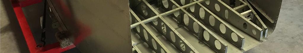
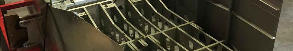
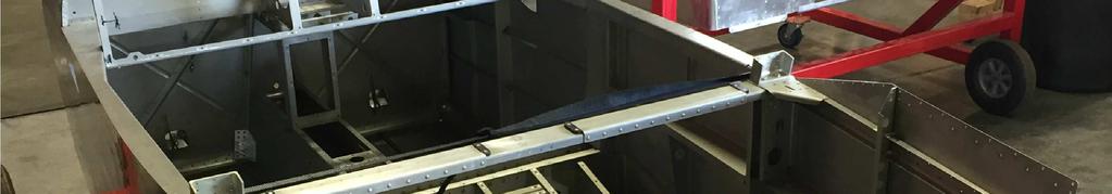
SECTION 22: FWD LOWER FUSELAGE VAN'S AIRCRAFT, INC F-1257 RUDDER PEDAL SUPPORT CHANNEL, 4 PLACES WD-1204 ENGINE MOUNT BRACKET, 2 PLACES
 SECTION 22: F-1257 RUDDER PEDAL SUPPORT CHANNEL, WD-1204 ENGINE MOUNT BRACKET, VAN'S AIRCRAFT, INC. FWD LOWER F-1201B FIREWALL SHELF FIREWALL BOTTOM FUSELAGE TUNNEL RIB F-1271-R FWD FUSE CORNER SKIN F-1288
Page: 42H-03 REV 1: In Figure 1, replace AN507-6R6 with AN507-6R8
 14401 Keil Road NE, Aurora, Oregon, USA 97002 PHONE 503-678-6545 FAX 503-678-6560 www.vansaircraft.com info@vansaircraft.com Service Letters and Bulletins: www.vansaircraft.com/public/service.htm REVISION
NEW PRODUCT RELEASE. PRODUCT/KIT NAME: 12 Stabilator Tip Fairing Kit
 14401 Keil Road NE, Aurora, Oregon, USA 97002 PHONE 503-678-6545 FAX 503-678-6560 www.vansaircraft.com info@vansaircraft.com Service Letters and Bulletins: www.vansaircraft.com/public/service.htm NEW PRODUCT
Page REV 1: Added "Step 4: Bend the tabs on the wiring channel to match the slant of the F L & -R Tunnel Sides."
 14401 Keil Road NE, Aurora, Oregon, USA 97002 PHONE 503-678-6545 FAX 503-678-6560 www.vansaircraft.com info@vansaircraft.com Service Letters and Bulletins: www.vansaircraft.com/public/service.htm REVISION
Page REV 1: In Step 1, added reference to fluid fitting clocking. Added Figure 2 and Figure 3.
 14401 Keil Road NE, Aurora, Oregon, USA 97002 PHONE 503-678-6545 FAX 503-678-6560 www.vansaircraft.com info@vansaircraft.com Service Letters and Bulletins: www.vansaircraft.com/public/service.htm DOCUMENTATION
REVISION DESCRIPTION:
 REVISION DESCRIPTION: 14401 Keil Road NE, Aurora, Oregon, USA 97002 PHONE 503-678-6545 FAX 503-678-6560 www.vansaircraft.com info@vansaircraft.com Service Letters and Bulletins: www.vansaircraft.com/public/service.htm
REVISION DESCRIPTION:
 14401 Keil Road NE, Aurora, Oregon, USA 97002 PHONE 503-678-6545 FAX 503-678-6560 www.vansaircraft.com info@vansaircraft.com Service Letters and Bulletins: www.vansaircraft.com/public/service.htm REVISION
REVISION DESCRIPTION:
 14401 Keil Road NE, Aurora, Oregon, USA 97002 PHONE 503-678-6545 FAX 503-678-6560 www.vansaircraft.com info@vansaircraft.com Service Letters and Bulletins: www.vansaircraft.com/public/service.htm REVISION
REVISION DESCRIPTION:
 14401 Keil Road NE, Aurora, Oregon, USA 97002 PHONE 503-678-6545 FAX 503-678-6560 www.vansaircraft.com info@vansaircraft.com Service Letters and Bulletins: www.vansaircraft.com/public/service.htm REVISION
VAN S AIRCRAFT, INC.
 VAN S AIRCRAFT, INC. 14401 Keil Road NE, Aurora, Oregon, USA 97002 PHONE 503-678-6545 FAX 503-678-6560 www.vansaircraft.com info@vansaircraft.com Service Letters and Bulletins: http://www.vansaircraft.com/public/notices.htm
REVISION DESCRIPTION:
 14401 Keil Road NE, Aurora, Oregon, USA 97002 PHONE 503-678-6545 FAX 503-678-6560 www.vansaircraft.com info@vansaircraft.com Service Letters and Bulletins: www.vansaircraft.com/public/service.htm REVISION
REVISION DESCRIPTION:
 REVISION DESCRIPTION: 14401 Keil Road NE, Aurora, Oregon, USA 97002 PHONE 503-678-6545 FAX 503-678-6560 www.vansaircraft.com info@vansaircraft.com Service Letters and Bulletins: www.vansaircraft.com/public/service.htm
ROLL BAR FRAME 2 PLACES F-1231A-FL ROLL BAR FRAME F-1231C INBOARD F-1231B OUTBOARD ROLL BAR STRAP BAGGAGE BULKHEAD
 SECTION 24iS/U: ROLLOVER F-1231A-FR ROLL BAR FRAME VAN'S AIRCRAFT, INC. F-1231A-AR ROLL BAR FRAME STRUCTURE F-1231E ROLL BAR SPLICE PLATE 2 PLACES F-1232A ROLL BAR BRACE F-01254-R-1 SUPPORT FRAME & F-01207
REVISION DESCRIPTION:
 REVISION DESCRIPTION: 1) Page: 12-03 REV 1: Step 1: and Figure 1: Final-Drill s.b. Match-Drill. Step 4: Updated flox mixture description to match later description (removed "peanut butter-like" description).
Page: MEMO: In Figure 3, "2X 1 3/32 [27.78 mm]" was "2X 1 3/32 [2.75 mm]"
![Page: MEMO: In Figure 3, 2X 1 3/32 [27.78 mm] was 2X 1 3/32 [2.75 mm]](/thumbs/73/68816766.jpg "Page: MEMO: In Figure 3, 2X 1 3/32 [27.78 mm] was 2X 1 3/32 [2.75 mm]") 14401 Keil Road NE, Aurora, Oregon, USA 97002 PHONE 503-678-6545 FAX 503-678-6560 www.vansaircraft.com info@vansaircraft.com Service Letters and Bulletins: www.vansaircraft.com/public/service.htm REVISION
14401 Keil Road NE, Aurora, Oregon, USA 97002 PHONE 503-678-6545 FAX 503-678-6560 www.vansaircraft.com info@vansaircraft.com Service Letters and Bulletins: www.vansaircraft.com/public/service.htm REVISION
SERVICE BULLETIN
 14401 Keil Road NE, Aurora, Oregon, USA 97002 PHONE 503-678-6545 FAX 503-678-6560 www.vansaircraft.com info@vansaircraft.com Service Letters and Bulletins: www.vansaircraft.com/public/service.htm SERVICE
F-1202D-L PANEL ATTACH STRIP F L UPPER FWD FUSELAGE SKIN RIB F CABIN EGRESS HANDLE F-1240B COVER PLATE
 SECTION 29iS/U: F-1202D-L PANEL ATTACH STRIP F-01240-1 UPPER FORWARD FUSELAGE SKIN (SHOWN TRANSPARENT) VAN'S AIRCRAFT, INC. FWD UPPER FUSELAGE F-00078 CABIN EGRESS HANDLE F-00077-L UPPER FWD FUSELAGE SKIN
"Figure 2: Trim Washer" was "Figure 1: Trim Washers". Page: 40A-06 REV 1: In Step 6, added "Fully torque the nut."
 14401 Keil Road NE, Aurora, Oregon, USA 97002 PHONE 503-678-6545 FAX 503-678-6560 www.vansaircraft.com info@vansaircraft.com Service Letters and Bulletins: www.vansaircraft.com/public/service.htm REVISION
NOTIFICATION
 14401 Keil Road NE, Aurora, Oregon, USA 97002 PHONE 503-678-6545 FAX 503-678-6560 www.vansaircraft.com info@vansaircraft.com Service Letters and Bulletins: www.vansaircraft.com/public/service.htm Date
36-01 REV 1: Updated figure to depict current F Bellcrank configuration.
 REVISION DESCRIPTION: 36-01 REV 1: Updated figure to depict current F-00067 Bellcrank configuration. 36-06 REV 1: Updated Figure 1 and Figure 2 to depict current F-00067 Bellcrank configuration. 36-07
NOTIFICATION
 14401 Keil Road NE, Aurora, Oregon, USA 97002 PHONE 503-678-6545 FAX 503-678-6560 www.vansaircraft.com info@vansaircraft.com Service Letters and Bulletins: www.vansaircraft.com/public/service.htm NOTIFICATION
1) Page: REV 5: Changed depiction to show added hardware and T-01220
 Page: REV 5: Changed depiction to show added hardware and T-01220") REVISION DESCRIPTION: 1) Page: 37-01 REV 5: Changed depiction to show added hardware and T-01220 Page: 37-02 REV 4: Added Figure 3 depicting Separating the T-01220 Doublers. Figure 4 was Figure 3. Added
REVISION DESCRIPTION: 1) Page: 37-01 REV 5: Changed depiction to show added hardware and T-01220 Page: 37-02 REV 4: Added Figure 3 depicting Separating the T-01220 Doublers. Figure 4 was Figure 3. Added
12.0 CONTROLS 3/3/2006. Page 1
 Page 1 Page 2 SR3500 Rudder Pedal Parts List ITEM DESCRIPTION PART NUMBER QTY 1 MASTER BRAKE PEDAL RP0015 2 2 SLAVE BRAKE PEDAL RP0016 2 3 PUSH ROD RP0017 4 4 SLAVE BRAKE TORQUE TUBE RP0018 2 5 MASTER
SECTION 26iS/U: FUEL TANK VAN'S AIRCRAFT, INC. T R OUTBOARD RIB IE-00001X MECHANICAL FUEL GAUGE T R INBOARD RIB T R
 VAN'S AIRCRAFT, INC. SECTION 26iS/U: IE-00001X MECHANICAL FUEL GAUGE T-01222-R OUTBOARD RIB FUEL TANK T-01223-R INBOARD RIB T-01228 RETURN LINE BRACKET T-01224-R INBOARD RIB T-01229 INLET ASSEMBLY T-01223-L
REVISION DESCRIPTION: REV 2: Steps re-written for clarity REV 2: Steps re-written for clarity.
 REVISION DESCRIPTION: 14-04 REV 2: Steps re-written for clarity. 14-05 REV 2: Steps re-written for clarity. SECTION 14: W-1012-L OUTBOARD W-1012-R TRIMMED OUTBOARD S W-1012-L OUTBOARD W-1025B-R FLAP HINGE
STOL CH F8-2 Front Floor Stiffener. Cut and position the Front Floor Stiffener to the Floor 7F8-7. Back drill through the Floor 7F8-7.
 Wait to drill the ends of the Seat Front 7F11-1 to the L angle on the cabin side at location A-A Ref 7-F-9 until after the Cabin Frame is installed. Ref Fuselage Cabin Frame, Section 10, page 11. NOTE:
Page: REV 3: Add drill and tap information to Figure 4 DRILL #3, TAP 1/4-28 BOTH ENDS.
 REVISION DESCRIPTION: 1) Page: 32-03 MEMO: Step 4 should not be bold. Fix WD-1213 callout in Figure 3. Page: 32-04 REV 3: Add drill and tap information to Figure 4 DRILL #3, TAP 1/4-28 BOTH ENDS. Add make
Section 75-ZA-3 Fin & Rudder Cable Fairing Installation
 Section 75-ZA-3 Fin & Rudder Cable Fairing Installation This manual has been prepared for installation of the Fin and Fairings. This photo assembly manual is intended as a supplement to the drawings. If
12NPR Reason For Revision
 12NPR 04-03-14-1 Reason For Revision 1) RV-12 SkyView Touch Avionics Kit 2) RV-12 SkyView AP-Knob Panels Kit (58) 3) Add instructions for installation of F-00062. 4) Allow use of lighter springs on RV-12
12/03 EXPLODED VIEW 1) L angles on first rear rib: moved from inboard to outboard side of rib (12/03)
 L angles on first rear rib: moved from inboard to outboard side of rib (12/03)") ZODIAC CH 601 XL Drawing list December 04, 2003 3 rd revision of 2 nd edition 12/03 Summary of revisions from 07/03 to 11/03 AIRFRAME 6-X-0 DRAWING LIST Dec 4, 2003 6-X-1 6-T-0 6-T-1 6-T-2 6-T-3 6-T-4
ZODIAC CH 601 XL Drawing list December 04, 2003 3 rd revision of 2 nd edition 12/03 Summary of revisions from 07/03 to 11/03 AIRFRAME 6-X-0 DRAWING LIST Dec 4, 2003 6-X-1 6-T-0 6-T-1 6-T-2 6-T-3 6-T-4
Section 75-FA-4. Forward Fuselage
 Section 75-FA-4 This manual has been prepared for assembly of the forward fuselage skins supplied with match drilled parts. This photo assembly manual is intended as a supplement to the drawings. If there
VAN'S AIRCRAFT, INC. SECTION 40: LIGHTING
 SECTION 40: LIGHTING RIGHT WING ASSEMBLY W-00014 LENS LN-200-1 WING TIP NAV/POSITION/ STROBE LIGHT LL-200 LANDING LIGHT W-1223E LENS BACKING STRIP, W-1222-R EXTENSION W-1223B-L LANDING LIGHT RIB NOTE:
AEROPRAKT SERVICE BULLETIN. No. SB A22LS-17 REPLACEMENT OF RUDDER CONTROL SYSTEM CABLES AND FAIRLEADS OF A-22, A-22L, A-22L2 AND A-22LS AIRCRAFT
 Aeroprakt Ltd AEROPRAKT SERVICE BULLETIN No. SB A22LS-17 REPLACEMENT OF RUDDER CONTROL SYSTEM CABLES AND FAIRLEADS OF A-22, A-22L, A-22L2 AND A-22LS AIRCRAFT Repeating symbols: Please, pay attention to
VAN'S AIRCRAFT, INC. SECTION 19: WING SYSTEMS ROUTING
 VAN'S AIRCRAFT, INC. SECTION 19: WING SYSTEMS ROUTING RIGHT WING ASSEMBLY WH-00011 WING TIP LIGHTING HARNESS WH-00013 AP SERVO HARNESS LEFT WING ASSEMBLY W-00027 PITOT LINE WH-00012 ADAHRS HARNESS WH-00011
FUSELAGE CABIN ASSEMBLY
 SECTION 3 Cabin Frame Ref Dwg 8FC-3 The Top of the Cabin Frame is level The distance between the front and rear wing attachment to fit the wings SECTION 3 - Page 1 of 10 CABIN FRAME 8F18-1 The TOP TUBES
FUSELAGE ASSEMBLY SECOND SECTION (of three)
") FUSELAGE ASSEMBLY SECOND SECTION (of three) 1 FRONT FLOOR ASSEMBLY The front floor assembly is fabricated from three pieces of the two ply pre-pregnated panel material supplied. The basic floor panel and
FUSELAGE ASSEMBLY SECOND SECTION (of three) 1 FRONT FLOOR ASSEMBLY The front floor assembly is fabricated from three pieces of the two ply pre-pregnated panel material supplied. The basic floor panel and
Airworthiness Directive Schedule
 Airworthiness Directive Schedule Aeroplanes Cessna 120 26 November 2015 Notes 1. This AD schedule is applicable to Cessna 120 aircraft manufactured under Federal Aviation Administration (FAA) Type Certificate
33T Braking system - toe brakes
 33T Braking system - toe brakes Overview Two separate brake systems are to be installed, one for each wheel brake. The two master cylinders provided require their operating lever to be substituted by a
AIRCRAFT LANDING GEAR CONSTRUCTION MANUAL
 APPENDIX AI KITPLANES FOR AFRICA AIRCRAFT LANDING GEAR CONSTRUCTION MANUAL Revision: C September 2008 Page L1 of 20 NOTE: Please read the General Manual before proceeding. Please read through the entire
TECHNICAL BULLETIN May 2013 Revision A, 11 July 2013 SUBJECT: TAIL ROTOR GEARBOX 3 PIECE FAIRING, MODIFICATION OF
 TECHNICAL BULLETIN 206-13-205 24 May 2013 Revision A, 11 July 2013 MODEL AFFECTED: 206A/B SUBJECT: TAIL ROTOR GEARBOX 3 PIECE FAIRING, MODIFICATION OF HELICOPTERS AFFECTED: Serial number 004 through 1251.
The engine cowling installation and firewall should be inspected and modified as specified in this Service Bulletin.
 Single Engine Service Bulletin August 25, 2008 TITLE ENGINE COWLING ALIGNMENT INSPECTION AND MODIFICATION EFFECTIVITY Model Serial Numbers 172R 17280001 thru 17280724 172S 172S8001 thru 172S8201 REASON
TEMPORARY REVISION NUMBER
 TEMPORARY REVISION NUMBER 7 DATED 1 DECEMBER 2011 MANUAL TITLE MANUAL NUMBER - PAPER COPY TEMPORARY REVISION NUMBER Model 188 & T188 Series 1966 Thru 1984 Service Manual D2054-1-13 D2054-1TR7 MANUAL DATE
SECTION 42D: SKYVIEW UPDATE INSTRUCTIONS WH SKYVIEW SL-40 HARNESS VAN'S AIRCRAFT, INC. F R INST STACK ANGLE
 SECTION 42D: VAN'S AIRCRAFT, INC. SKYVIEW UPDATE F-00026-R INST STACK ANGLE INSTRUCTIONS WH-00028 SKYVIEW SL-40 HARNESS F-00026-L INST STACK ANGLE F-00027-L COM SUPPORT NOTE: DOUBLE CHECK THAT YOU HAVE
4-Bulkheads. Bulkheads. December XLR Page 4-1
 Bulkheads December 2007 04-XLR Page 4-1 This Page Intentionally Left Blank Page 4-2 04-XLR December 2007 Contents 4.0 - Chapter Preface...4-4 4.0.1 - Parts List... 4-4 4.0.2 - Tools List... 4-4 4.0.3 -
Improved Fire Protection Retro-Fit Manual for US LSA Airplanes Fire Wall Protecting
 THIS DOCUMENT AND THE TECHNICAL DATA HEREON DISCLOSED ARE PROPRIETARY TO AND SHALL NOT BE USED, RELEASED, OR DISCLOSED IN WHOLE OR IN PART WITHOUT EXPRESS WRITTEN PERMISSION FROM Page: 2 Table of Contents
FIGURE 2: ADDING FITTINGS TO BRAKE ASSEMBLY (RIGHT SHOWN) FIGURE 1: ATTACHING AND ALIGNING THE MAIN GEAR AXLES
 FIGURE 1: ATTACHING AND ALIGNING THE MAIN GEAR AXLES") VAN'S AIRCRAFT, INC. Step 2: Apply pipe thread sealant and attach the fluid fittings to the brake as shown in Figure 2. Note that the brakes should mirror each other when installed. Step 1: Bolt the main
VAN'S AIRCRAFT, INC. Step 2: Apply pipe thread sealant and attach the fluid fittings to the brake as shown in Figure 2. Note that the brakes should mirror each other when installed. Step 1: Bolt the main
ZODIAC 601 XL. Trim the outboard corner of the front flange of the center spar 6W4-1. Corner should not touch the side of the cabin floor skin 6B10-1.
 Trim the outboard corner of the front flange of the center spar 6W4-1. Corner should not touch the side of the cabin floor skin 6B10-1. Tape the side skins to the cabin floor skin (area in front of the
SECTION 35iS/U: LANDING GEAR & ENGINE MOUNT
 WD-1221 ENGINE MOUNT STANDOFF SECTION 35iS/U: LANDING GEAR & ENGINE MOUNT U-01203E-1 INBOARD DOUBLER PLATE U-01203B-1 INBOARD WEAR PLATE U-01203C-1 BEARING PLATE U-01203-2 (U-01203-1 SHOWN) INBOARD MAIN
TECHNICAL BULLETIN May 2013 SUBJECT: TAIL ROTOR GEARBOX 3 PIECE FAIRING, MODIFICATION OF
 TECHNICAL BULLETIN 206-13-205 24 May 2013 MODEL AFFECTED: 206A/B SUBJECT: TAIL ROTOR GEARBOX 3 PIECE FAIRING, MODIFICATION OF HELICOPTERS AFFECTED: Serial number 004 through 1251. COMPLIANCE: At customer
REVISION LIST CHAPTER 22: CABIN VENTILATION
 REVISION LIST CHAPTER 22: The following list of revisions will allow you to update the Legacy construction manual chapter listed above. Under the Action column, R&R directs you to remove and replace the
Service Bulletin No.: DAC Rev 3 Date Issued: October 27, 1999 Title: 2-Speed Electric Prime Fuel Pump Page: 1 of 8
 Title: 2-Speed Electric Prime Fuel Pump Page: 1 of 8 1. ATA Code: 2820 2. Effectivity: DA20-C1 Aircraft from S/N C0001 up to and including S/N C0089 3. General: This service bulletin addresses the installation
Service Bulletin. SB-GA Issue 1. Subject: Horizontal Stabiliser Attachment Area Inspection and Reinforcement. Applicability: Amendments:
 PO Box 881, Morwell, Victoria 3840, Australia Ph + 61 (0) 3 5172 1200 Fax + 61 (0) 3 5172 1201 www.mahindraaerospace.com Service Bulletin SB-GA8-2016-163 Issue 1 OPTIONAL Subject: Horizontal Stabiliser
The tie to tube front windshield was rounded to avoid a distorted by this point.
 CHANGES IN AIRFRAME IBIS MAGIC GS-700 (2.008) Drilling of plastic polycarbonate drill with 9/64 so that it is an amplitude when riveting. The tie to tube front windshield was rounded to avoid a distorted
AIRCRAFT FINISHING Assembling the Front Seat Frames
 AIRCRAFT FINISHING Assembling the Front Seat Frames Front Seat (shown with custom leather upholstery) The front seat frame assembly is supplied without upholstery. The seat back is hinged at the bottom
Jabiru Aircraft Pty. Ltd. Final Inspection Checklist J200/400. Firewall forward components
 Jabiru Aircraft Pty. Ltd. Final Inspection Checklist J200/400 Registration No: Aircraft Checklist Pre Ground Test Model: Aircraft Serial No: Firewall forward components Propeller: Prop Size: 60 x 53 Other:
TEMPORARY REVISION NUMBER
 TEMPORARY REVISION NUMBER 8 DATED 1 DECEMBER 2011 MANUAL TITLE MANUAL NUMBER - PAPER COPY TEMPORARY REVISION NUMBER 1978 Thru 1986 Model R182 & TR182 Service Manual D2069-3-13 D2069-3TR8 MANUAL DATE 15
Jabiru Aircraft Pty. Ltd. Final Inspection Checklist. Engine Compartment
 Jabiru Aircraft Pty. Ltd. Final Inspection Checklist Registration No: Aircraft Checklist Pre Ground Test Model: Serial No: Engine Compartment Propeller: Prop Size: 60 x 53 Other:.. Propeller Serial No:
FAA approval has been obtained on technical data in this publication that affects airplane type design.
 Single Engine Service Bulletin January 28, 2008 TITLE ENGINE COWLING ALIGNMENT INSPECTION AND MODIFICATION EFFECTIVITY Model Serial Numbers 172R 17280725 thru 17281262 172S 172S8202 thru 172S10006 REASON
1) Page: 45A-11 REV 1: In the list of audio pot settings before Step 1 AutoP Volume off should be AutoP Volume off SkyView/max Garmin
 Page: 45A-11 REV 1: In the list of audio pot settings before Step 1 AutoP Volume off should be AutoP Volume off SkyView/max Garmin") REVISION DESCRIPTION: 1) Page: 45A-11 REV 1: In the list of audio pot settings before Step 1 AutoP Volume off should be AutoP Volume off SkyView/max Garmin 2) Page: 45A-10 REV 4: Add information for setting
REVISION DESCRIPTION: 1) Page: 45A-11 REV 1: In the list of audio pot settings before Step 1 AutoP Volume off should be AutoP Volume off SkyView/max Garmin 2) Page: 45A-10 REV 4: Add information for setting
FIREWALL FORWARD GENERAL
 GENERAL The configuration of the aircraft forward of the firewall will vary from aircraft to aircraft depending on engine selection and other variables. The effort here must be well thought-out and neatly
SECTION 4: RV-12 PARTS INDEX
 SECTION 4: RV-12 PARTS INDEX PART NUMBER NOMENCLATURE SUB-KIT SECT# PAGE# PART TYPE: MAKE FROM MATERIAL: PART NUMBER NOMENCLATURE SUB-KIT SECT# PAGE# PART TYPE: MAKE FROM MATERIAL: A-1201A-L INBD NOSE
HARTZELL PROPELLER INC.
 HARTZELL PROPELLER INC. One Propeller Place Piqua, Ohio 45356-2634 U.S.A. Telephone: 937.778.4200 Fax: 937.778.4391 MANUAL REVISION TRANSMITTAL Manual (61-00-11) Propeller Owner's Manual and Logbook REVISION
REVISION LIST CHAPTER 21: FLAP SYSTEM COMPLETION
 REVISION LIST CHAPTER 21: The following list of revisions will allow you to update the Legacy construction manual chapter listed above. Under the Action column, R&R directs you to remove and replace the
Vehicle Final Inspection Checklist Form
 Vehicle Final Inspection list Form Wheelchair Lifts / Platforms: 1. Platform angle is adjusted as specified by manufacturer 2. Lift location in entryway (clears door, operators and door posts) 3. All switches
INSTALLATION INSTRUCTIONS EXTERNAL AUXILIARY FUEL SYSTEM P/N
 INSTALLATION INSTRUCTIONS EXTERNAL AUXILIARY FUEL SYSTEM P/N 41228-000-002-007 Page 1 of 45 List of Revisions Rev. Date Pages Description Approved IR 09/12/05 All Initial Release N/C All Updated to Apical
GlaStar and Sportsman Service Bulletin 67
 GlaStar and Subject: Applicability: Issue: Compliance Time: Elevator counterweights All GlaStar and Aircraft Counterweight attachment to elevator end rib At or before next condition inspection Discussion
Airframe Group Item Description Part Number Size
 Parts List: LS-1 Airframe Group Canopy - LS1 Aluminum sheet, 6061 T6 1241-8.050" x 1.5" 8" Angle, aluminum 6061-T6 987-6 2" x 2" x.125" 6" Bar stock, acetal 42367 1" x 1.25" 3" Bar stock, alum 1125-8 1"
SECTION 47: COWL BAFFLE VAN'S AIRCRAFT, INC. CB RIGHT AFT BAFFLE CB CYLINDER 3 BAFFLE VA-187 4" FLANGED DUCT
 SECTION 47: CB-00014 CYLINDER 3 BAFFLE CB-00015 RIGHT AFT BAFFLE VA-187 4" FLANGED DUCT COWL BAFFLE CB-00031-R MAGNETO COOLING TUBE CB-00016 AFT CENTER BRACKET CB-00017 LEFT AFT BAFFLE CB-00013 RIGHT AIR
SERVICE BULLETIN SB
 TITLE LIGHTS - LED TAIL POSITION LIGHT INSTALLATION EFFECTIVITY MODEL UNIT NUMBERS 500 (Citation) -0001 thru -0349 with SB500-33-07 incorporated 500 (Citation I) -0350 thru -0528 with SB500-33-07 incorporated,
Service Bulletin No.: DAC Rev 5 Date Issued: 26 November 2010 Title: Engine Fuel System Conversion from IO-240-B17B to IO-240-B3B
 Page: 1 of 10 1. ATA Code: 7300 2. Effectivity: DA20-C1 S/N C0380 to C0456, C0467 to C0471, C0482 to C0488, C0496, C0497, C0504, C0505, C0511 to C0513 and C0536 or earlier aircraft on which SB DAC1-73-01
SERVICE KIT thru , 631, 634, 675 R thru R F thru F FR thru FR
 TITLE SEAT BELT AND SHOULDER HARNESS KIT INSTALLATION EFFECTIVITY MODEL SERIES SERIAL NUMBERS 182 33000 thru 18268368 182 613, 631, 634, 675 R182 R18200001 thru R18201973 F182 F18200001 thru F18200169
REVISION LIST CHAPTER 24: MISCELLANEOUS SYSTEMS
 REVISION LIST CHAPTER 24: The following list of revisions will allow you to update the Legacy construction manual chapter listed above. Under the Action column, R&R directs you to remove and replace the
TEMPORARY REVISION NUMBER
 TEMPORARY REVISION NUMBER 7 DATED 1 DECEMBER 2011 MANUAL TITLE MANUAL NUMBER - PAPER COPY TEMPORARY REVISION NUMBER FR172 Reims Rocket 1968 Thru 1976 Service Manual D849-5-13 D849-5TR7 MANUAL DATE 15 August
REVISION LIST CHAPTER 13: FIREWALL FORWARD (PART 1)
") REVISION LIST CHAPTER 13: FIREWALL FORWARD (PART 1) The following list of revisions will allow you to update the Legacy construction manual chapter listed above. Under the Action column, R&R directs you
REVISION LIST CHAPTER 13: FIREWALL FORWARD (PART 1) The following list of revisions will allow you to update the Legacy construction manual chapter listed above. Under the Action column, R&R directs you
SERVICE BULLETIN SB00029 Rev B Page 1 of 19
 SERVICE BULLETIN SB00029 Rev B Page 1 of 19 This Service Bulletin meets requirements of ASTM F2295-06. It is a Safety Directive for the purpose of compliance with 14 CFR 91.327(b)(4). EFFECTIVE DATE: This
12NPR Reason For Revision
 12NPR 04-03-14-1 Reason For Revision 1) RV-12 SkyView Touch Avionics Kit 2) RV-12 SkyView AP-Knob Panels Kit (58) 3) Add instructions for installation of F-00062. 4) Allow use of lighter springs on RV-12
Ballistic Recovery Systems, Inc. PARACHUTE INSTALLATION MANUAL BRS-1350 LS, AMD 601XL Zodiac
 Ballistic Recovery Systems, Inc. PARACHUTE INSTALLATION MANUAL BRS-1350 LS, AMD 601XL Zodiac BRS Document Number: 020019-PM Rev A Date: 09/05/07 BRS Unit Serial Number: Aircraft Registration Number: Abstract
2000 SERIES SPEEDBRAKE INSTALLATION MANUAL PA28/PA32 STC # SA00762SE
 INSTALLATION REPORT NO. 08067 Serial Number PRECISE FLIGHT, INC. 800-547-2558 2000 SERIES SPEEDBRAKE INSTALLATION MANUAL PA28/PA32 STC # SA00762SE NOTE: READ THESE DIRECTIONS BEFORE STARTING! CHECK FOR
Section 75-CA-2. Elevator Controls
 Section 75-CA-2 This manual has been prepared for assembly of the. This photo assembly manual is intended as a supplement to the drawings. If there is any discrepancy between this manual and the drawings,
Items Included in kit: FOLLOWING ARE THE BRAKE LINE RETROFIT KIT ITEMS
 Thank you for purchasing your RV-14 Brake and Fuel Line Kit. Please note that these directions are updated periodically as required and the current version will always be located on our website. These
Service Bulletin No.: DAC Rev 2 Date Issued: Oct 04, 2016 Title: Installation of LED Anti-Collision and Position light Assembly
 Page: 1 of 9 1. ATA Code: 3340 2. Effectivity: DA20-C1 Aircraft S/N C0001 to C0647 3. General: This Service Bulletin addresses the replacement of Whelen s Anti- Collision /Position Light assembly (A600PG-14/A600PR-14)
2000 SERIES SPEEDBRAKE INSTALLATION MANUAL MOONEY M20 SERIES & M22 STC NO. SA4342NM NOTE: READ THESE DIRECTIONS BEFORE STARTING!
 INSTALLATION REPORT NO. 08059 Serial Number PRECISE FLIGHT, INC. 800-547-2558 2000 SERIES SPEEDBRAKE INSTALLATION MANUAL MOONEY M20 SERIES & M22 NOTE: READ THESE DIRECTIONS BEFORE STARTING! THIS DOCUMENT
N398CM. RC-3 Serial Number 387 Zero Timed Restoration Details
 RC-3 Serial Number 387 Zero Timed Restoration Details WING GROUP: Complete disassembly of wings, flaps, ailerons, lift struts, floats, and float struts. removal, alodine dip, and epoxy prime, w/bms 10-11.
TORNADO II, S, & SS FUSELAGE TRACKING
 TORNADO II, S, & SS FUSELAGE TRACKING 92-INS-0176-C Nose Fork Assembly Instructions Approved 92-INS-0178-D Spindle and Brake Assembly Approved 92-INS-0181-F Anti Servo Control Assembly Approved 92-INS-0182-C
Speed Kit (Tri-Gear aircraft)
") Speed Kit (Tri-Gear aircraft) Classification: Applicability: Compliance: Optional Tri-gear Aircraft N/A Introduction The addition of fairings to the flap hinges, landing gear legs and wheels are found
Speed Kit (Tri-Gear aircraft) Classification: Applicability: Compliance: Optional Tri-gear Aircraft N/A Introduction The addition of fairings to the flap hinges, landing gear legs and wheels are found
Airworthiness Directive Schedule
 Airworthiness Directive Schedule Aeroplanes 30 July 2015 Notes 1. This AD schedule is applicable to De Havilland Canada DHC-2 Beaver MK I aircraft manufactured under Transport Canada Type Certificate Number:
CIRRUS AIRPLANE MAINTENANCE MANUAL
 JACKING 1. DESCRIPTION Three jack points, located at each wing tiedown and tail tiedown, are provided to perform maintenance operations. Tie-down rings must be removed and replaced with jack points prior
EXPRESS ASSEMBLY MANUAL SECTION 3 F5-RG/FT WING ASSEMBLY. Procedure 3.050A INSTALLATION OF AILERON TORQUE TUBE ASSEMBLY
 Procedure 3.050A INSTALLATION OF AILERON TORQUE TUBE ASSEMBLY In this procedure The aileron torque tube will be assembled and installed in the wing. Part Number Description Quantity 111-24-050 Torque Tube,
2000 SERIES PA-30 / PA-39 STC NO. SA00233SE PA-24 STC NO. SA4150NM
 INSTALLATION REPORT NO. 08073 Serial Number PRECISE FLIGHT, INC. 800-547-2558 2000 SERIES SPEEDBRAKE INSTALLATION MANUAL PA-30 / PA-39 STC NO. SA00233SE PA-24 STC NO. SA4150NM NOTE: READ THESE DIRECTIONS
Requires: 100 c.c. gasoline engine, 4-channel radio w/ 9 high torque servos.
 (A300) Requires: 00 c.c. gasoline engine, -channel radio w/ 9 high torque servos. Specifications Wing Span Wing Area Flying Weight Fuselage Length 6 in / 950 mm 3700 sq in / 38.7 sq dm 38.5 Ib / 7.5 kg
PARAVION TECHNOLOGY, INC AIRWAY AVENUE FT. COLLINS, COLORADO 80524
 PARAVION TECHNOLOGY, INC. 2001 AIRWAY AVENUE FT. COLLINS, COLORADO 80524 DOCUMENT NO. INSTALLATION INSTRUCTIONS BELL 206A/B/L/L1/L3/L4 HELICOPTER MODELS Page i Rev. H, 02/06/06 REVISIONS REV. DATE DESCRIPTION
SERVICE BULLETIN SB0017 Rev A Page 1 of 5
 SERVICE BULLETIN SB0017 Rev A Page 1 of 5 EFFECTIVE DATE: This Service Bulletin is effective November 15, 2016. SUBJECT: MODELS AFFECTED: COMPLIANCE TIME: PURPOSE: STABILIZER YOKE CC18-0002 THROUGH CC18-0083
A Product Line of Sonex Aircraft LLC 511 Aviation Road Oshkosh, WI Tel. (920) Fax. (920)
 Fax. (920)") A Product Line of Sonex Aircraft LLC 511 Aviation Road Oshkosh, WI 54902 Tel. (920)-231-8297 Fax. (920)-426-8333 www.aeroconversions.com Rev C, 03/01/2013 (7 pages) The AeroConversion's Pitch Trim unit
A Product Line of Sonex Aircraft LLC 511 Aviation Road Oshkosh, WI 54902 Tel. (920)-231-8297 Fax. (920)-426-8333 www.aeroconversions.com Rev C, 03/01/2013 (7 pages) The AeroConversion's Pitch Trim unit
D'Shannon Aviation PANEL INSTALLATION INSTRUCTIONS
 D'Shannon Aviation PANEL INSTALLATION INSTRUCTIONS Disconnect the battery posts 1. Windshield Removal NOTE: If the aircraft is equipped with a D'Shannon speed sloped windshield, you will not have to do
SD3-60 STRUCTURAL REPAIR MANUAL STABILIZER (FIN) - STRUCTURAL IDENTIFICATION
 - STRUCTURAL IDENTIFICATION") SRM 12.0.0.0VERTICAL STABILIZER (FIN) STRUCTURAL IDENTIFICATION 1. General This section identifies the skin panels and structural components of the vertical stabilier. Details are given of specific location;
SRM 12.0.0.0VERTICAL STABILIZER (FIN) STRUCTURAL IDENTIFICATION 1. General This section identifies the skin panels and structural components of the vertical stabilier. Details are given of specific location;
SD3-60 STRUCTURAL REPAIR MANUAL - STRUCTURAL IDENTIFICATION
 SD3-60 STRUCTURAL REPAIR MANUAL z SRM 1.0.0.0FUSELAGE - STRUCTURAL IDENTIFICATION 1. Introduction This chapter indicates the location of the strcu tural members of the fuselage and shows methods for repairing
Ram 1500 Crew Cab A Ram 2500/3500 Crew Cab A
 I N S T A L L A T I O N G U I D E APPLICATION AMP Part # Ram 1500 Crew Cab 2013-2015 77138-01A Ram 2500/3500 Crew Cab 2013-2015 77138-01A Note:The application works only on the Crew Cab model Vehicles.