Items Included in kit: FOLLOWING ARE THE BRAKE LINE RETROFIT KIT ITEMS
|
|
|
- Melanie Skinner
- 5 years ago
- Views:
Transcription


1 Thank you for purchasing your RV-14 Brake and Fuel Line Kit. Please note that these directions are updated periodically as required and the current version will always be located on our website. These instructions are meant to serve as a general guide for the installation of these packages. However, the builder is responsible for verifying that this kit is installed in a safe manner for their aircraft. As always, if you have any questions, we are available for telephone or support. This kit is available in several different versions. This manual will cover the complete kit. If you have only purchased a partial kit, you only need to follow the directions for the components that you purchased. Items Included in kit: FOLLOWING ARE THE BRAKE LINE RETROFIT KIT ITEMS size 90 degree AN fittings - (QTY 10 for RV-14A, and QTY 8 for RV-14) size AN Tee (QTY 1 for RV - 14A and QTY 1 for RV-14) size 45 degree AN Fittings - (QTY 2 for RV-14 Only) 4. F14116B-L QTY 1 5. F14116B-R QTY 1 6. F14116C-L QTY 1 in RV-14A Kit only 7. F14116C-R QTY 1 in RV-14A Kit only 8. F14116D-L QTY 1 in RV-14 Kit only 9. F14116D-R QTY 1 in RV-14 Kit only 10.F14116A-L QTY F14116A-R QTY 1 12.In RV14/14A kits with Parking brake installation, F14116C-L, C-R, D-L, and D-R are replaced. Parking brake installations use two hoses from the pedal to the parking brake valve, and two hoses from the parking brake valve out to the respective gear assemblies.
2 FOLLOWING ARE THE FUEL LINE RETROFIT KIT ITEMS F14109-C QTY 1 (This is a flex hose in our kit) F14109-B QTY 1 Rigid Tube Assembly F14109A-L QTY 1 Rigid Tube Assembly F14109B-L QTY 1 Rigid Tube Assembly Note that Duplex valve installations are a bit more custom. F B will be custom replaced. F14109A-L and F14109B-L are each replaced with two rigid tube assemblies. FUEL LINE KIT INSTALLATION Our non duplex fuel line installation package consists of 3 rigid tubes and one flex hose. The flex hose goes from the pump to the firewall, and the three rigid tubes are used from the valve to the pump and also from the valve to the respective wing fittings. All the lines are very straightforward to install and will save countless hours over fabricating your own tubes. For the rigid tube assemblies that go from the valve to the wings, we recommend the following. Hand tighten the assembly at the valve first. Make sure that the AN fitting at the wing root is loose so that it can swing freely and make attachment easier. Attach the tube at the wing root Tighten everything up Note: The rigid tubing is 5052 aluminum, which is a soft grade of aluminum but of a much higher quality than the 3003 soft tubing that it supplied with the kit. A very slight amount of pre load may be necessary to install the tubing in your aircraft. The important thing is that the tube attaches perpendicular to the fittings and fits well. The tolerances are very tight, and we are able to build these tubes with a very high amount of repeatability. All of our beta testers reported that these tubes drop right in. Any slight variance should be such that you can attach everything and it will allow it to fall into place during final tightening. If you have any questions during the installation, please feel free to contact us. Note 2: For duplex valve installations, please note the following information. The bottom rigid tube assemblies are straightforward and will install into existing holes. The top rigid tube assemblies require that the holes in the clips be drilled out to 3/8 in
3 order to accommodate the larger diameter lines. In addition, depending on how accurately these are drilled...the tube may not be in perfect alignment with the pre drilled exit hole on the fuselage for the pass through bulkhead fitting (purchased separately). In order to accommodate this, the tubes are slightly shorter than required which allows you to utilize a step drill to drill the fuselage exit hole to 5/8, which is slightly over sized for the bulkhead fitting. The spacer to utilize is a standard Vans AN-6D Spacer. The spacer will need to have a flat filed on it in order to accommodate rivet clearance. This is shown in the duplex pictures in this document.


4 Following are pictures of the fuel line assemblies for a non duplex valve standard setup.

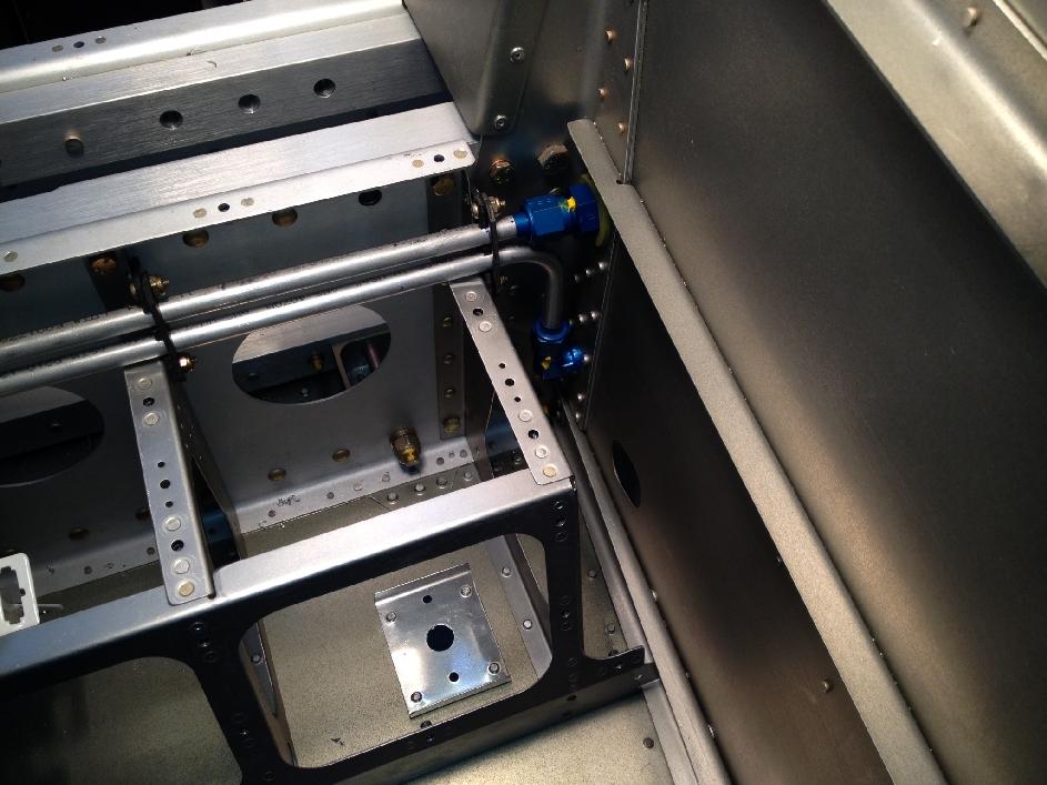
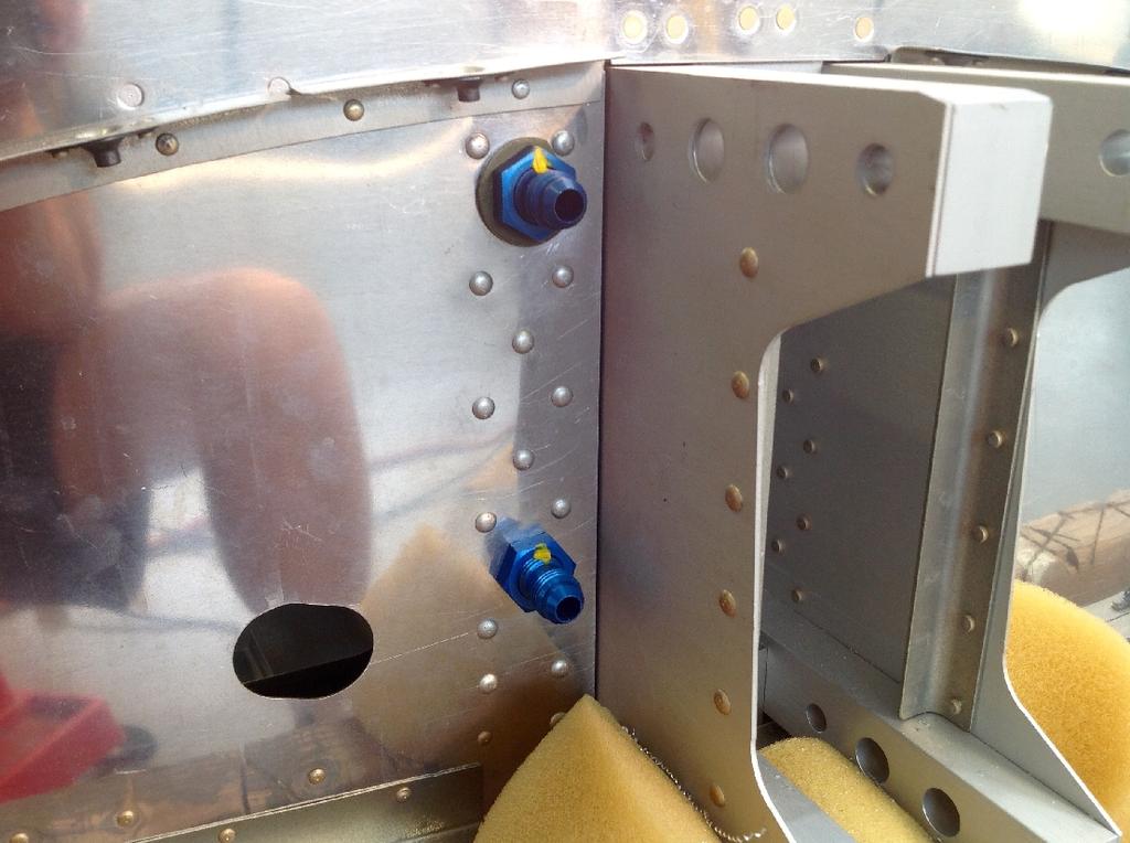
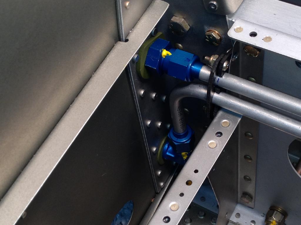
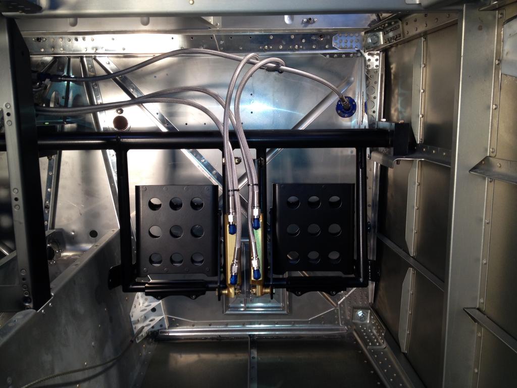
5 DUPLEX FUEL VALVE INSTALLATION PICTURES
6
7
8 BRAKE LINE KIT INSTALLATION The brake line kit is designed as an extremely compact, lightweight and very high quality alternative to the standard plastic RV-14 lines. This kit when ordered in its complete form comes with ALL the hoses and fittings required to complete this installation. The non parking brake installation includes everything required. The parking brake installation consists of fittings and hoses ONLY and requires fabrication of brackets as well as purchasing the valve and valve actuator assemblies. Tim Olson was our initial beta tester and did a very detailed installation description on his website with a multitude of pictures. We are including that writeup at the end of this document for use as a guide when installing this package. Below are a few important notes: 1. We have shortened the long hoses by several inches from the initial beta test show in Tim's pictures. This allows for an even better fit with less excess hose. 2. The RV-14 rudder pedals can be permanently mounted in one of three different locations forward and aft. We build your hoses so that they will fit in any of the three positions. This means that if the pedals are moved to one of the forward two positions, the hoses will be slightly long and may need to be zip tied for a better appearance. 3. Please remember to utilize a thread sealant on the NPT portion of the fittings. No thread sealant is needed on the flare portion of the fittings. 4. If you want to adapt a parking brake, we are including pictures immediately below which show this. 5. PARKING BRAKE INSTALLATION *IMPORTANT* We highly recommend attaching all hoses by hand to your parking brake valve BEFORE fabricating and determining your exact final parking brake mounting. This will ensure that the angle and orientation of the valve will allow the hoses to sit nicely and move freely with the pedals throughout the full range of motion. The hoses are long enough to allow a bit of flexibility in the mounting locations, but we have found that the nicest and easiest installations have mounted the park valve AFTER attaching all hoses by hand to determine the absolute best placement. You will notice that the fore/aft placement of the parking brake valve varies slightly in some of the these pictures. It depends on which pedal position you utilize. 6. List of Items to purchase for a parking brake installation: 1. Matco PVPV-D Parking Brake valve 2. A-730 Glide Free control (This is what some of our beta testers utilized for a parking brake valve cable. It can be purchased from Spruce) 3. Spruce Part # This is the end that mounts into the parking brake valve and fits with the A-730 glide cable.

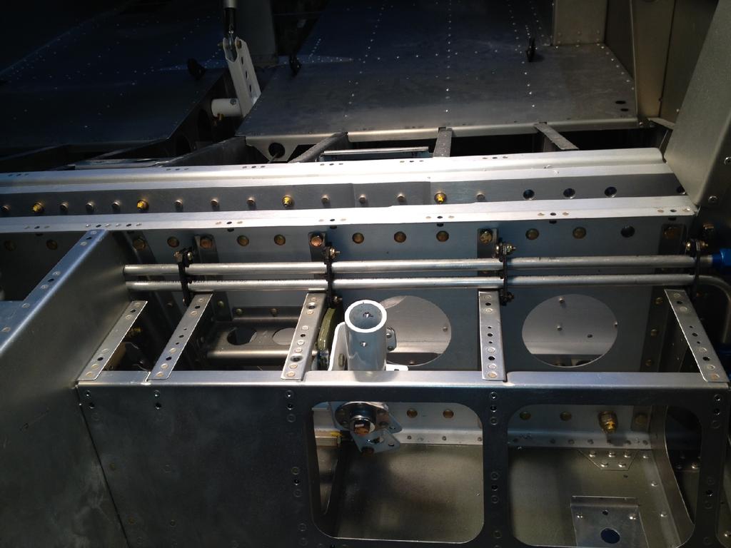
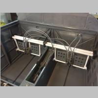
9 When installing with a parking brake, please note that an angle bracket will require fabrication to mount the valve. Shown in this picture is the angle bracket fabricated by the builder. The builder will also need to fabricate a mounting angle to hold the adel clamp and actuator cable in place.

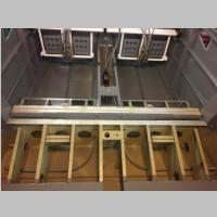
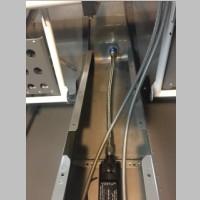
10 PARKING BRAKE INSTALLATION IN RV-14A. Valve location 1. Mounting bracket needs to be fabricated. Valve not included, but all hoses and AN fittings are.

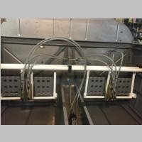
11 PARKING BRAKE INSTALLATION IN RV-14. Valve location 1. Mounting bracket needs to be fabricated. Valve not included, but all hoses and AN fittings are. Please note that both valve mounting locations will utilize the same length hoses. Builder is responsible for determining how to mount valve, but this approximate location works with the hose lengths.
12

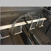
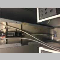
13 PARKING BRAKE INSTALLATION IN RV-14. Valve location 2. Mounting bracket needs to be fabricated. Valve not included, but all hoses and AN fittings are. Please note that both valve mounting locations will utilize the same length hoses. Builder is responsible for determining how to mount valve, but this approximate location works with the hose lengths.


14 Pictured below are images of how some beta installers mounted their valve as well as routed their parking brake actuator cable.
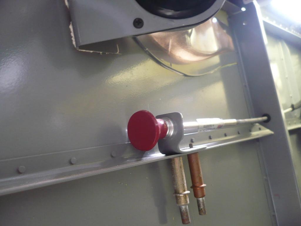
15

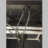
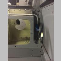
16 Here is an image of the RV-14 Tailwheel Cabin hoses WITHOUT a parking Brake.

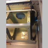
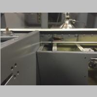
17 Here is an image of the RV-14A Nosewheel Installation without a parking brake valve.

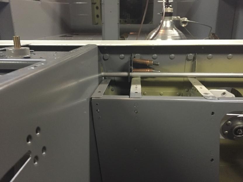
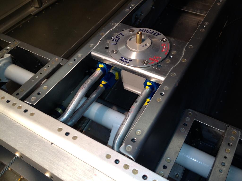
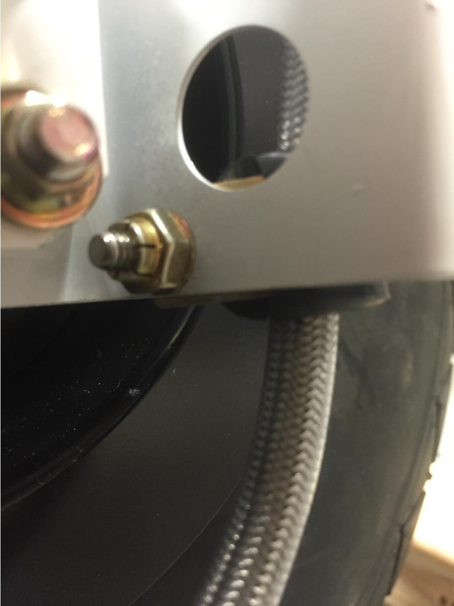
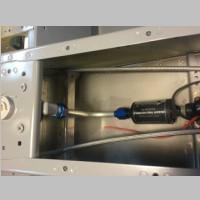
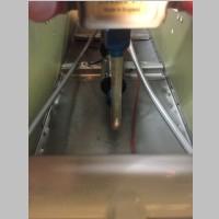
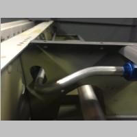
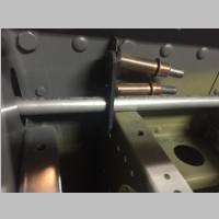
18 Pictured below is the AN tee that mounts into the reservoir as well as the correct orientation for the hoses that come out of it down to the copilot brake pedals. Please note that the orientation of the 90 degree fitting when tightened down will affect how much slack is in that hose. So, if it appears to be too loose, you can move the 90 degree fitting a little bit up and vice versa. This will give you a nice fit and a great looking final assembly.
 Qty 2 816-3d fittings (RV-14A for top of gear leg fitting) Qty 2 823-3d fittings (RV-14A caliper fittings) QTY 4 823-3d fittings (RV-14 Tailwheel only.")
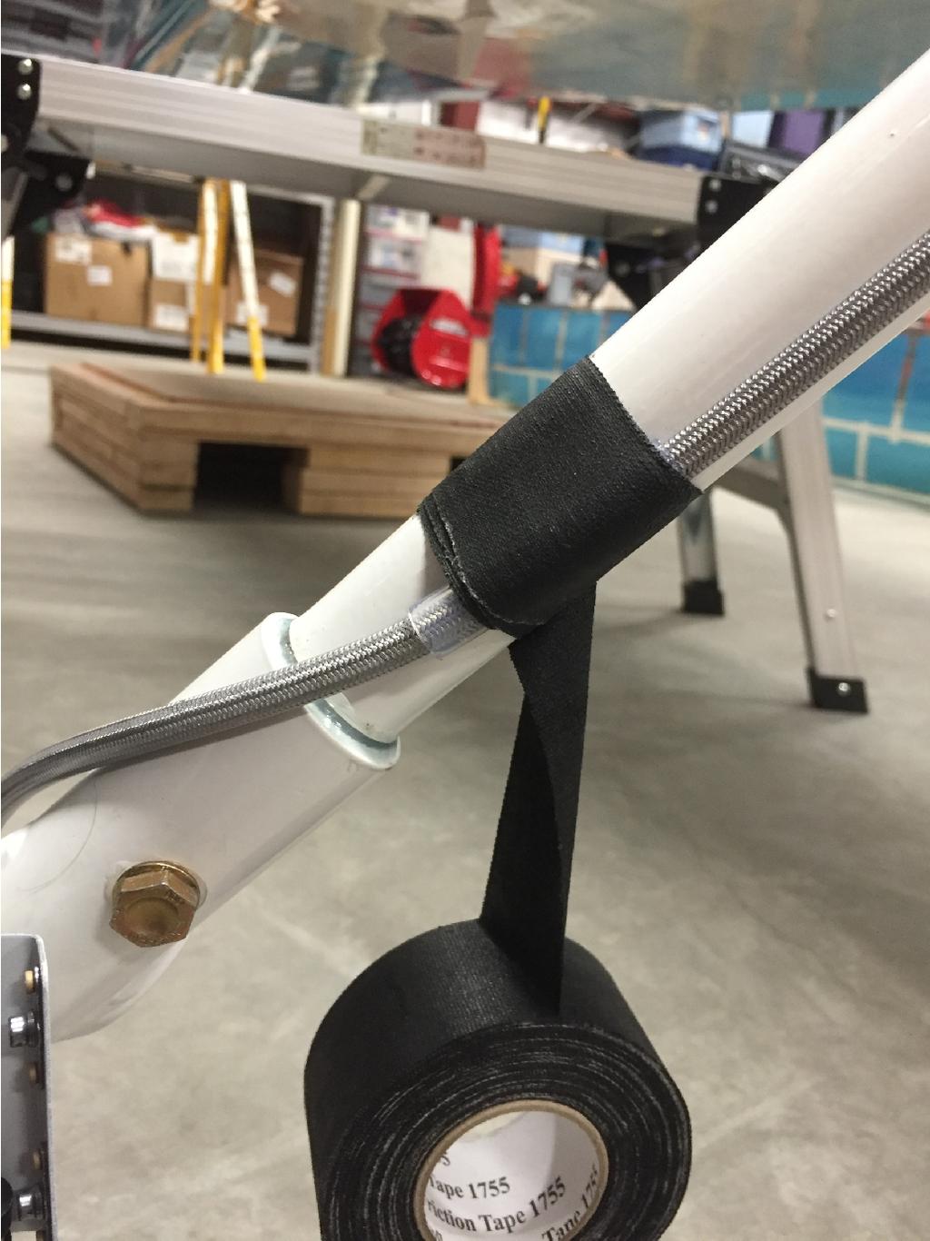
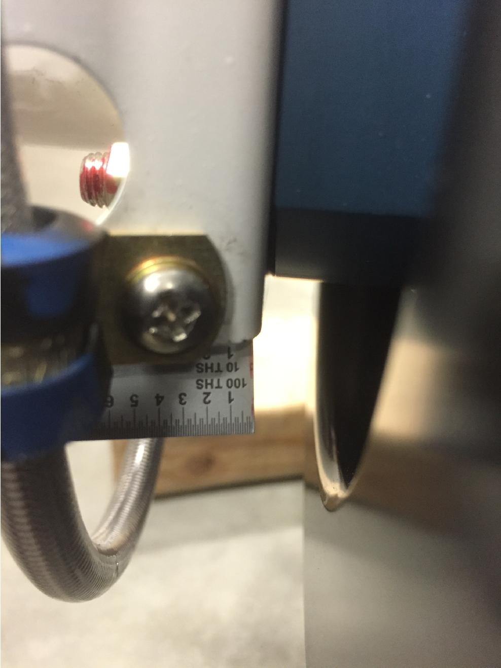
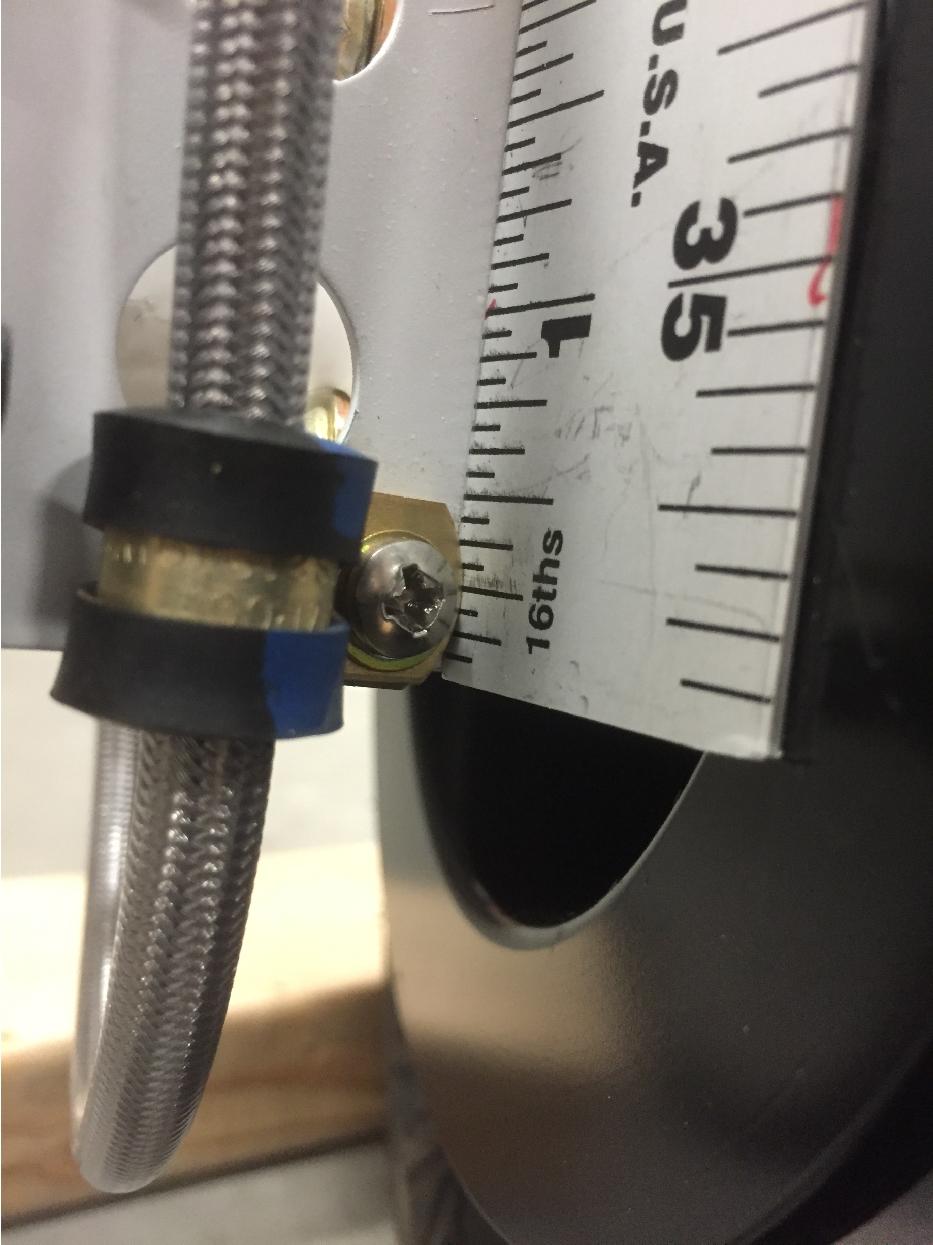
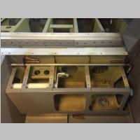
19 GEAR LEG HOSE KIT RV-14 and RV-14A Your RV-14 Gear Leg hose kit comes with the following components: hoses (one for each gear leg) Qty d fittings (RV-14A for top of gear leg fitting) Qty d fittings (RV-14A caliper fittings) QTY d fittings (RV-14 Tailwheel only. 45 degree fittings used at top of gear leg and at caliper) 5. WDG Clamps and installation hardware for the wrap of hose at caliper. Please utilize the following pictures as a guide for your installation. The first two pictures are the RV-14A installation. The second set of pictures shows the RV-14 Tailwheel install. Ensure that there is enough slack in hose to allow for normal movement as well as to ensure that no undue force is being placed on the calipers.


20 Here is the location used by our beta tester for the clamp. It is 2.25 from the edge and 1/4 down The pictures shown below are for the RV14 Tailwheeel install.
21


22 Tim Olson Writeup on package installation One thing I knew going into the fuel and brake line section was that I wasn't going to be using the included fuel and brake lines by Van's. Van's uses plastic tubing for the brake lines, which I personally consider inadequate, even if they do hold the pressure. There isn't enough chafe protection, I want more durability, I want more resistance from becoming brittle, and I want something that will hold up far better. Solid lines aren't really a good option for brakes in the RV14 due to the routing they take. In the RV-10 I had switched to -3 sized stainless braided teflon hoses, with a clear vinyl over protection cover, and I wanted to do the same thing in the RV-14, so I contacted Steve at Aircraft Speciatly and Tom at TS Flightlines. Steve is in Wisconsin like I am, so I knew turnaround time would be good, and Steve and Tom often collaborate to work out good packages for RV's. I knew they could make me the braided brake hoses I wanted. \ I also remembered from the RV-10 how much easier it was to work with flex fuel lines, so I wanted to do some of that on the RV-14 as well. First of all, the Van's supplied aluminum tube I found much harder to get good lines out of in my last build. I ran into one batch of tubing that wanted to crack and split a lot, so ordered another roll which wasn't as bad. But, the tubing is very soft and flexible which made it nick real easily with the tubing bender. I wanted to avoid all of that so I intended to use flex hoses which would be strong, last a lifetime, and perhaps route easier. What I found in the end is that flex teflon may not be the perfect thing in some areas of the RV-14. In the RV-14 you're probably better off going with hard lines for the side wall to fuel valve, and a Teflon hose, although it did work, was flexed in a tighter bend radius than I wanted when going from valve to fuel pump. So that was a good place for a hard line too. In regards to the tubing, the hard lines I felt would be acceptable if they were done in 5052-O. Steve has been working at getting a CNC bender all set up for making hard lines, so that would be a great project for him that would save me some time. The one line I did want flex was the line to the firewall from the fuel pump. This one would be real easy to make in solid tube, but the firewall in the RV-14 is very thin, and if there were ever any sort of landing incident, that line could easily be bent out of position and cracked, spraying fuel into the cabin. So I really wanted to go with a good stainless braided flex line to the firewall for that reason, keeping in mind that my daughters may be flying this plane. The first thing I had to do to switch to teflon brake lines was figure out where to route them. On the forward side, no big deal, but through the spar there were 2.375" holes drilled per side,.5" center to


23 center, and the plans had you run both hoses though the holes on the Right side of the plane. I'm sure this makes routing up the the wire chase to the panel area convenient. The problem is, the teflon hoses need.5" holes for the nuts that are preinstalled, whereas van's uses cheap compression fittings on plastic hose that can be cut and threaded through BEFORE the ends are put on. You can't drill those 2 holes to.5" because the holes will start to run together and leave no room for snap bushings. Without knowing the other things coming in the finishing kit, I had to take what I knew and make some educated guesses as to alternative ways to run the lines. I could drill more holes but I wanted to avoid that if possible. Also, those holes were in great places. It didn't appear that those holes on the left side of the plane would be used for wires, due to the other places I could see that were for running wires. It did appear that those could be for a pitot or static line, but those would be easily run through any of the 4 holes. So I decided that rather than run the brake lines only on the right side, and then cross one line under the center pushrods to the left of the plane, I'd use the bottom hole on each side, keeping the left hose on the left and the right on the right. This allows you to drill the holes out to.5" and preserve 2 other holes as.375" as before. I may end up having to route my static or pitot lines on the upper hole on either side if that's what is coming, but I'm kind of guessing that nothing will run though those holes anyway. Certainly nothing major and non-changeable like flight controls. Some of the pictures above show the holes in question. Above are also photos of the flex lines, and one of the prototype lines from valve to fuel filter. Steve made that line fit perfectly the first time...i was very impressed. You'll notice that when I enlarged the holes for the brake lines, I was able to do it with a hex shaft unibit and hex drill extension. This allowed me to drill a 1/2" hole and then pass the bit through the spar to the gap between front and rear half of the spar, and continue drilling. I used a right angle drill to enlarge the holes out to the side walls through the seat ribs.


24 As I got the final fit brake and fuel hoses, I took some good pictures of them. Above are the hoses to the firewall. A 90 degree fitting was used on one of the hoses to give a nicer route with it's straight hose-mate down to the rudder pedals. The 2nd photo shows the final valve to fuel pump hose that also fit perfectly. The 3rd photo shows the flex line to the firewall. And the other photos above and below show the brake lines and routing. it's a nice clean package. The -3 sized brake lines are only about.275" or so, so not much larger than the.25" plastic.

25


26 Above are lots more pictures of the brake and fuel lines. The above line is the fuel valve to side wall line that was bent in 5052-O by Aircraft Specialty. It also fit perfectly the first time and fit right in the Van's provided plastic fuel line standoffs. The photos 2 rows below show the brake hose package again. One thing to make note of...i drilled a 2nd hole though the center rudder pedal brace, to fit a second SB750 snap bushing for the brake lines. Those snap bushings have to get slit, as do the SB500-6 bushings that you have to use in the. 5" holes to the aft portion of the plane. (Mine is a nose wheel plane) So altogether it requires the hoses, -3 elbows and a -3 Tee fitting, and some new snap bushings for routing the hoses. It is well worth the effort. It took me only about 5-10 minutes to enlarge all of the required holes and I had the whole brake line package installed within about 45 minutes.
27 On behalf of Aircraft Specialty and TS Flightlines. Thank you for purchasing our package. We appreciate you allowing us to earn your business, and we look forward to continuing to develop and innovate new products and working with you in the future.
PLEASE NOTE: A COPY OF THE THERMOSTASIS SPECIFIC DIRECTIONS ARE ATTACHED TO THE LAST PAGE OF THIS DOCUMENT.
 Thank you for purchasing your Rotax 912 Thermostasis Install Kit. Please note that these directions are updated periodically as required and the current version will always be located on our website. These
COMANCHE GEAR Regent Circle Naples, FL Phone & fax 239/ Cell 239/ Main gear doors miscellaneous
 COMANCHE GEAR 10340 Regent Circle Naples, FL 34109 Phone & fax 239/593-6944 Cell 239/404-7524 www.comanchegear.com Main gear doors miscellaneous Here are a few thoughts to consider if you are having a
Page REV 1: Added 'Step 2: See the "REMOVE THIS TAB, BOTH SIDES" callout near Detail A. Modify four SB375-4 Snap Bushings as shown.
 14401 Keil Road NE, Aurora, Oregon, USA 97002 PHONE 503-678-6545 FAX 503-678-6560 www.vansaircraft.com info@vansaircraft.com Service Letters and Bulletins: www.vansaircraft.com/public/service.htm REVISION
Page: REV 3: Add drill and tap information to Figure 4 DRILL #3, TAP 1/4-28 BOTH ENDS.
 REVISION DESCRIPTION: 1) Page: 32-03 MEMO: Step 4 should not be bold. Fix WD-1213 callout in Figure 3. Page: 32-04 REV 3: Add drill and tap information to Figure 4 DRILL #3, TAP 1/4-28 BOTH ENDS. Add make
Page: REV 1: In Step 4 "a minimum of 1/16 [1.6 mm] gap" was "an approximately 1/16 [1.6 mm] gap."
![Page: REV 1: In Step 4 a minimum of 1/16 [1.6 mm] gap was an approximately 1/16 [1.6 mm] gap.](/thumbs/72/66557156.jpg "Page: REV 1: In Step 4 a minimum of 1/16 [1.6 mm] gap was an approximately 1/16 [1.6 mm] gap.") 14401 Keil Road NE, Aurora, Oregon, USA 97002 PHONE 503-678-6545 FAX 503-678-6560 www.vansaircraft.com info@vansaircraft.com Service Letters and Bulletins: www.vansaircraft.com/public/service.htm REVISION
14401 Keil Road NE, Aurora, Oregon, USA 97002 PHONE 503-678-6545 FAX 503-678-6560 www.vansaircraft.com info@vansaircraft.com Service Letters and Bulletins: www.vansaircraft.com/public/service.htm REVISION
Main Gear Doors (Apr 2009) Matt Kurke, ICS #10288
 Matt Kurke, ICS #10288") Main Gear Doors (Apr 2009) Matt Kurke, ICS #10288 A few thoughts to consider if you are having a problem with the main gear doors retracting and/or fitting properly on your Comanche Read section 6-39 (below)
Main Gear Doors (Apr 2009) Matt Kurke, ICS #10288 A few thoughts to consider if you are having a problem with the main gear doors retracting and/or fitting properly on your Comanche Read section 6-39 (below)
Let's take a look at the components that make up this retrofit hose kit.
 Thank you for purchasing your Rotax 912 Fuel Hose Kit. Please note that these directions are updated periodically as required and the current version will always be located on our website. These instructions
My Hawk build Part 8 by Stuart Clarke
 My Hawk build Part 8 by Stuart Clarke Front hubs, brakes and brake lines. There was still no news on my rear springs so I thought I d find something else to get on with. I had the front hubs, brake calipers
12.0 CONTROLS 3/3/2006. Page 1
 Page 1 Page 2 SR3500 Rudder Pedal Parts List ITEM DESCRIPTION PART NUMBER QTY 1 MASTER BRAKE PEDAL RP0015 2 2 SLAVE BRAKE PEDAL RP0016 2 3 PUSH ROD RP0017 4 4 SLAVE BRAKE TORQUE TUBE RP0018 2 5 MASTER
SECTION 35iS/U: LANDING GEAR & ENGINE MOUNT
 WD-1221 ENGINE MOUNT STANDOFF SECTION 35iS/U: LANDING GEAR & ENGINE MOUNT U-01203E-1 INBOARD DOUBLER PLATE U-01203B-1 INBOARD WEAR PLATE U-01203C-1 BEARING PLATE U-01203-2 (U-01203-1 SHOWN) INBOARD MAIN
Replacing the Vacuum Servo on 700/900 with ACC/ECC Double-Acting Servos. [Procedure from Dick Riess, to whom thanks are given; some notes from Dan]
![Replacing the Vacuum Servo on 700/900 with ACC/ECC Double-Acting Servos. [Procedure from Dick Riess, to whom thanks are given; some notes from Dan]](/thumbs/89/98811956.jpg "Replacing the Vacuum Servo on 700/900 with ACC/ECC Double-Acting Servos. [Procedure from Dick Riess, to whom thanks are given; some notes from Dan]") Replacing Vacuum Servos in ACC/ECC-Equipped 700/900 Cars FAQ Home Volvo Maintenance FAQ for 7xx/9xx/90 Cars HVAC Home OEM Manual Procedure for Replacing Vacuum Servos. See the FAQ file for a large.pdf
Replacing Vacuum Servos in ACC/ECC-Equipped 700/900 Cars FAQ Home Volvo Maintenance FAQ for 7xx/9xx/90 Cars HVAC Home OEM Manual Procedure for Replacing Vacuum Servos. See the FAQ file for a large.pdf
Air Compressor/Water Pump IV - Pilot Valve Stem, Test & Installation
 Page 1 of 8 Air Compressor/Water Pump Part IV Pilot Valve Stem, Test & Installation Nelson Riedel Nelson@NelsonsLocomotive.com Initial: 1/13/04 Last Revised: 0 Valve Test: I decided to test the steam valves
BMW E46 Convertible Hydraulic Line #23 Replacement Guide Created by taylor192 of E46Fanatics.com
 BMW E46 Convertible Hydraulic Line #23 Replacement Guide Created by taylor192 of E46Fanatics.com BMW E46 Line #23 Replacment Guide, page 1 of 23 Background: Line #23 runs from the valve block on the driver's
PYRTE. Building The Front Axle, Fork and Steering
 PYRTE Building The Front Axle, Fork and Steering The front axle on this traction engine is a very simple affair, in that it is a rectangular steel rod, sat on edge, with a pivot in the centre, which is
1) Page: REV 5: Changed depiction to show added hardware and T-01220
 Page: REV 5: Changed depiction to show added hardware and T-01220") REVISION DESCRIPTION: 1) Page: 37-01 REV 5: Changed depiction to show added hardware and T-01220 Page: 37-02 REV 4: Added Figure 3 depicting Separating the T-01220 Doublers. Figure 4 was Figure 3. Added
REVISION DESCRIPTION: 1) Page: 37-01 REV 5: Changed depiction to show added hardware and T-01220 Page: 37-02 REV 4: Added Figure 3 depicting Separating the T-01220 Doublers. Figure 4 was Figure 3. Added
4.6L Oil Filter Relocation Kit, (OC-7)
") 3430 Sacramento Dr., Unit D San Luis Obispo, CA 93401 Telephone: 805/544-8748 Fax: 805/544-8645 www.maximummotorsports.com 4.6L Oil Filter Relocation Kit, 2003-04 (OC-7) Filter Mount Installation 4. Remove
3430 Sacramento Dr., Unit D San Luis Obispo, CA 93401 Telephone: 805/544-8748 Fax: 805/544-8645 www.maximummotorsports.com 4.6L Oil Filter Relocation Kit, 2003-04 (OC-7) Filter Mount Installation 4. Remove
*Some speedometers have these additional electronic connections. If yours does, then remove the smaller slotted screws shown.
 www.odometergears.com 1981-1985 240 Cable-Driven Speedometers (NOT for 1986 and later electronic units) http://www.davebarton.com/240-odometer-repair.html For this set of instructions below, I will not
Steeda Sport Mustang Lowering Springs (2005+) - Installation Instructions
 - Installation Instructions") Steeda Sport Mustang Lowering Springs (2005+) - Installation Instructions The below installation instructions work for the following products: Steeda Sport Mustang Lowering Springs (2005+) Please read
Steeda Sport Mustang Lowering Springs (2005+) - Installation Instructions The below installation instructions work for the following products: Steeda Sport Mustang Lowering Springs (2005+) Please read
"Figure 2: Trim Washer" was "Figure 1: Trim Washers". Page: 40A-06 REV 1: In Step 6, added "Fully torque the nut."
 14401 Keil Road NE, Aurora, Oregon, USA 97002 PHONE 503-678-6545 FAX 503-678-6560 www.vansaircraft.com info@vansaircraft.com Service Letters and Bulletins: www.vansaircraft.com/public/service.htm REVISION
Section 13. Tail Rotor Drive. RotorWay International A600 TALON Construction Manual. Section 13. Page A
 RotorWay International Page A Tail Rotor Drive Procedures covered in this section: Install driveshafts and gearboxes; install drive belt and tensioner; fabricate and install tail rotor pitch actuator arms;
Timing belt change. Timing belt change
 Timing belt change Put 2 new Gates T275 timing belts on today. Tensioner drilled smooth and tight with less than 16,000 miles on her decided not to change the tensioners just the belts. You'll need some
REVISION DESCRIPTION:
 14401 Keil Road NE, Aurora, Oregon, USA 97002 PHONE 503-678-6545 FAX 503-678-6560 www.vansaircraft.com info@vansaircraft.com Service Letters and Bulletins: www.vansaircraft.com/public/service.htm REVISION
RIGGING THE FLIGHT CONTROLS
 RIGGING THE FLIGHT CONTROLS Rigging refers to the installation and adjustment of the rods that move flight surfaces in response to inputs from the controls of the helicopter. These rods are cut to length,
W123 Transmission Vacuum Modulator Adjustment DIY - measure it the 'right' way
 W123 Transmission Vacuum Modulator Adjustment DIY - measure it the 'right' way Why do you need to do this?: You need to do this to properly check the internal hydraulic pressure of the transmission, either
Gearbox Assembly 101. Introduction. Before Beginning. By Mark Schutzer 4/13/06
 Gearbox Assembly 101 By Mark Schutzer 4/13/06 Introduction If you are planning to re-motor an old brass locomotive you may want to upgrade to a new gearbox at the same time. The early 60 s and 70 s gearboxes
REVISION DESCRIPTION:
 REVISION DESCRIPTION: 14401 Keil Road NE, Aurora, Oregon, USA 97002 PHONE 503-678-6545 FAX 503-678-6560 www.vansaircraft.com info@vansaircraft.com Service Letters and Bulletins: www.vansaircraft.com/public/service.htm
How To: Fix That Ugly Hanging E-Brake Cable A CFans Members Mod Project by dirtydawg
 How To: Fix That Ugly Hanging E-Brake Cable A CFans Members Mod Project by dirtydawg Skill Level: Easy Disclaimer: Please use caution and seek professional assistance when necessary. ColoradoFans.com,
I n s t r u c t i o n M a n u a l. Instruction Manual SPECIFICATION
 I n s t r u c t i o n M a n u a l Instruction Manual SPECIFICATION - Wingspan: 3200mm (125,9 in) - Length: 1650mm (64,9 in) - Flying weight: 3000gr 3200gr - Wing area: 64.5 dm2 - Wing loading: 46g/dm2
Restoring the Strategic Air & Space Museum s E-4B Model
 Restoring the Strategic Air & Space Museum s E-4B Model By Don Joy IPMS Fort Crook I received a request from the SASM (Strategic Air and Space Museum) to do a restoration of the model. They had a member
$1.00 FOR THE TQIO/RCIO
 $1.00 FOR THE TQIO/RCIO m mm HDBBYSHOP Champion Jay Halsey has an impressive track record. One of Jay's advantages is a whisper smooth tranny thanks to his dad, Jim. Now you can build a Halsey transmission!
Hard Bar Sport, M1/M2 Hard Core Hardtop, M2 Sport, and Xtreme Installation Instructions
 HARDWARE KIT: Hard Bar Sport, M1/M2 Hard Core Shoulder Harness Guide Relocation Assemblies: 2-3/8" X 1" grade 8 bolts 4-3/8" flat washers 2-3/8" lock nuts 2 - brass bushings 2 - plastic trim caps 2-3/8"
FUSELAGE ASSEMBLY SECOND SECTION (of three)
") FUSELAGE ASSEMBLY SECOND SECTION (of three) 1 FRONT FLOOR ASSEMBLY The front floor assembly is fabricated from three pieces of the two ply pre-pregnated panel material supplied. The basic floor panel and
FUSELAGE ASSEMBLY SECOND SECTION (of three) 1 FRONT FLOOR ASSEMBLY The front floor assembly is fabricated from three pieces of the two ply pre-pregnated panel material supplied. The basic floor panel and
Connecting the rear fog light on the A4 Jetta, while keeping the 5 Light Mod
 Connecting the rear fog light on the A4 Jetta, while keeping the 5 Light Mod DISCLAIMER: I'm human and make mistakes. If you spot one in this how to, tell me and I'll fix it This was done on my 99.5 Jetta.
WARNING: the engine does not come with oil in it. Please fill the oil before starting. The 200cc hardknock requires 9/10 of a quart of oil.
 WARNING: the engine does not come with oil in it. Please fill the oil before starting. The 200cc hardknock requires 9/10 of a quart of oil. Things needed for assembly. -2 tubes of blue loc-tite. I don
JEEP JK4 STEP SLIDER INSTALLATION BD-SS-100-JK4
 JEEP JK4 STEP SLIDER INSTALLATION BD-SS-100-JK4 PARTS LIST QTY DESCRIPTION 1 Drivers Side Slider Assembly 1 Passenger Side Slider Assembly 1 Wiring Harness and Fuse 1 Double Sided Sticky Squares and Alcohol
4TH GEN SEATS IN A 3RD GEN TRUCK
 4TH GEN SEATS IN A 3RD GEN TRUCK by Flopster843 02 Oct 2016 If you drive a 3rd generation Dodge Ram truck, I am sure you have discovered that the OEM seats are not the greatest (Figure 1.) They are extremely
4x4 actuator "Cable Froze" 1988 s S-10 Forum
 Page 3 of 17 Converting a vacuum actuator to a locking cable system on a 1995 Chevy S10 Blazer 4x4 Many call this a posi-lock system. I spent a total of only $25.50 USD on this project. Other comparable
RECOMMENDED MOTOR AND BATTERY SET UP
 SPECIFICATION - Wingspan: 1404mm (55.3in) - Length: 1134mm (44. 6 in) - Flying weight: 3.2-3.4 kg - Covering type: Genuine ORACOVER - Spinner size: scale type (not included) - Radio: 4 channel minimum
Let's take a look at the components that make up this retrofit hose kit.
 Thank you for purchasing your Rotax 912 Fuel Hose Kit. Please note that these directions are updated periodically as required and the current version will always be located on our website. These instructions
GM C10 Street Grip
 Part # 11365010/11365110-1973-1987 GM C10 StreetGrip Front Components 11369590 Delrin Control Arm Bushings 11369300 Drop Spindles 11362350/11362351 Front CoilSpring Kit 11369515 Front HQ Series Shocks
ESPA3D Photo Essay One page ESPA3D Plans are HERE Back to Spad Plans Index
 1 of 8 8/29/2012 12:28 PM ESPA3D Photo Essay One page ESPA3D Plans are HERE Back to Spad Plans Index This little airplane has turned out to be one of the most fun Spad projects we've ever done! It is built
How I installed new brake pads on my i with Sport Package (should be fine for other E39 s) By Robert B.
 By Robert B.") How I installed new brake pads on my 1999 528i with Sport Package (should be fine for other E39 s) How I installed new brake pads on my 1999 528i with Sport Package (should be fine for other E39 s) By
How I installed new brake pads on my 1999 528i with Sport Package (should be fine for other E39 s) How I installed new brake pads on my 1999 528i with Sport Package (should be fine for other E39 s) By
RHINO SUSPENSION SYSTEM INSTALLATION INSTRUCTIONS
 PARTS INCLUDED: 2 FRONT UPPER A-ARMS 2 FRONT LOWER A-ARMS 2 UNI-BALL JOINTS 2 UNI-BALL JOINT STUDS 2 UNI-BALL JOINT CAPS 2 RETAINING RINGS 1 FRONT SHOCK ASSEM. 2 DELRON STEERING STOPS 2 SHOCK MOUNT SPACERS
Table of Contents. Tail Wheel Assembly Installation.. page 01. Stabilizer Installation.. page 02. Fin Installation.. page 03
 Table of Contents Tail Wheel Assembly Installation.. page 01 Stabilizer Installation.. page 02 Fin Installation.. page 03 Elevator and Rudder Hinge Installation.. page 04 Rudder Controls.. page 05 Elevator
Adjusting brake shoes for AutoPark parking brake
 Adjusting brake shoes for AutoPark parking brake This document is a compilation of several separate writeups. What we're trying to do here is consolidate the necessary information needed for you to make
36-01 REV 1: Updated figure to depict current F Bellcrank configuration.
 REVISION DESCRIPTION: 36-01 REV 1: Updated figure to depict current F-00067 Bellcrank configuration. 36-06 REV 1: Updated Figure 1 and Figure 2 to depict current F-00067 Bellcrank configuration. 36-07
REVISION LIST CHAPTER 18: BRAKE SYSTEMS. The following list of revisions will allow you to update the Legacy construction manual chapter listed above.
 REVISION LIST CHAPTER 18: BRAKE SYSTEMS The following list of revisions will allow you to update the Legacy construction manual chapter listed above. Under the Action column, R&R directs you to remove
ASSEMBLY INSTRUCTIONS FOR PART NUMBER GROUP
 ASSEMBLY INSTRUCTIONS FOR DYNAPRO 6 BIG BRAKE FRONT HAT KIT, 1.19 DIAMETER VENTED ROTOR 1990-005 ACURA/CIVIC ( LUG) 000-003 CIVIC SI ( LUG) 007 - PRESENT HONDA FIT FOR FACTORY 6 mm DISC SPINDLE PART NUMBER
upper and lower ball joints ( I went with Moog from rockauto.com): two K80026 and two K8607T
: two K80026 and two K8607T") Parts required: two 5C3Z*4A322*AA = hub / steering knuckle o-ring two AC3Z*1S175*A = updated axle shaft "dust seal" two 5C3Z*3254*A = steering knuckle / axle shaft seal upper and lower ball joints ( I
Parts required: two 5C3Z*4A322*AA = hub / steering knuckle o-ring two AC3Z*1S175*A = updated axle shaft "dust seal" two 5C3Z*3254*A = steering knuckle / axle shaft seal upper and lower ball joints ( I
BBK Ceramic Long Tube Headers (99-04 Cobra and Mach 1) - Installation Instructions
 - Installation Instructions") BBK Ceramic Long Tube Headers (99-04 Cobra and 03-04 Mach 1) - Installation Instructions The below installation instructions work for the following products: BBK Ceramic Long Tube Headers (99-04 Cobra
BBK Ceramic Long Tube Headers (99-04 Cobra and 03-04 Mach 1) - Installation Instructions The below installation instructions work for the following products: BBK Ceramic Long Tube Headers (99-04 Cobra
SHARK UPPER WINDSHIELD FRAME & WINDSHIELD REPLACEMENT. Text and Photos by TOM BENFORD
 Text and Photos by TOM BENFORD I purchased a fathom green 69 big-block tri-power T-top coupe with only 42,000 original miles on it recently. I'm the third owner of the car, and I got it for a very good
UrS6 Brake Servo Replacement Douglas Fifield July 2006
 UrS6 Brake Servo Replacement Douglas Fifield (douglas.fifield@gmail.com) July 2006 This write-up covers the replacement of the brake servo on a 95.5 S6. The master cylinder remained intact and connected,
COLD AIR INTAKE INSTALLATION INSTRUCTIONS
 COLD AIR INTAKE INSTALLATION INSTRUCTIONS # D760-0030 Fits: 2007-10 135i (E82, E88; with N54 engine) 2007-08 335i/xi (E90) 2007-10 335i (E92, E93; with N54 engine) Congratulations for being selective enough
No Modify Power Brake Kit Instructions
 No Modify Power Brake Kit Instructions Above are photos of the kit as shipped. Included is the booster, bracket, master cylinder, master cylinder brake lines, adjustable pushrod with rubber seal and vacuum
2001 V70 T5 ETM Removal and Cleaning Directions
 2001 V70 T5 ETM Removal and Cleaning Directions Howard Cheng howardc64@gmail.com 10/24/05 Version 1.4 Read this before you start I performed this ETM cleaning because I had gotten 2 reduced performance
BMW 528i E39 Trunk Harness Repair
 My problems started when I got a false alarm about the trunk lid being open. It went away the next day, but then I noticed the trunk light was out. I checked the bulb and it was fine. After reading the
FITTING OIL TEMP AND PRESSURE GUAGES
 FITTING OIL TEMP AND PRESSURE GUAGES this guide is of reference to fitting an oil temp and pressure sender/ sensor into a sandwich plate- not the sump plug temp sensor (although it wouldn't be much different
FIGURE 2: ADDING FITTINGS TO BRAKE ASSEMBLY (RIGHT SHOWN) FIGURE 1: ATTACHING AND ALIGNING THE MAIN GEAR AXLES
 FIGURE 1: ATTACHING AND ALIGNING THE MAIN GEAR AXLES") VAN'S AIRCRAFT, INC. Step 2: Apply pipe thread sealant and attach the fluid fittings to the brake as shown in Figure 2. Note that the brakes should mirror each other when installed. Step 1: Bolt the main
VAN'S AIRCRAFT, INC. Step 2: Apply pipe thread sealant and attach the fluid fittings to the brake as shown in Figure 2. Note that the brakes should mirror each other when installed. Step 1: Bolt the main
Severe Duty Oil Filter Relocation Kit (OC-9)
") 3430 Sacramento Dr., Unit D San Luis Obispo, CA 93401 Telephone: 805/544-8748 Fax: 805/544-8645 www.maximummotorsports.com Severe Duty Oil Filter Relocation Kit (OC-9) Filter Mount Installation 4. Remove
3430 Sacramento Dr., Unit D San Luis Obispo, CA 93401 Telephone: 805/544-8748 Fax: 805/544-8645 www.maximummotorsports.com Severe Duty Oil Filter Relocation Kit (OC-9) Filter Mount Installation 4. Remove
~~~~~~~~~~~~~~~~~~~~~~~~~~~~~~~~~~~~~~~~~~~~~~~~ ~~~~~~~~~~~~~~~~~~~~~~~~~~~~~~~~~~~~~~~~~~~~~~~~
 ~~~~~~~~~~~~~~~~~~~~~~~~~~~~~~~~~~~~~~~~~~~~~~~~ GSB Design Concepts Runnin' At Redline 7/9/17 ~~~~~~~~~~~~~~~~~~~~~~~~~~~~~~~~~~~~~~~~~~~~~~~~ Guest Shot: Gene Mills I've known Gene for a number of years,
Throttle Cable Pull - Patent Pending By: NetGain Controls, Inc.
 Throttle Cable Pull - Patent Pending By: NetGain Controls, Inc. Powering the future! Installation Guide 2011 All Rights Reserved NetGain Controls, Inc. 1 of 8 Introduction Thank you for purchasing a NetGain
2010 Toyota Prius Fog Light Retrofit
 2010 Toyota Prius Fog Light Retrofit A DIY prospective Last updated: Friday, December 25, 2009 *** Disclaimer Use this document and its contents at your own risk! *** Forward: This document was compiled
Street-Lynx By. Reilly MotorSports, Inc. Installation Manual
 Street-Lynx By Reilly MotorSports, Inc. Installation Manual 1 1- Begin by removing your original rear suspension disconnect your brake lines, E-brake cables, and remove the driveshaft. To prevent fire
Dual Remote Filtration System Installation and Servicing Instructions
 IMPORTANT NOTICE Read all instructions completely before attempting to install this unit. Improper installation could result in serious system and/or equipment damage. The installation of this system is
Brake System Rebuilding the brake calipers
 Page 1 of 39 Brake System Rebuilding the brake calipers Written by the backyard hack mechanic Sean750 Document history: # 14 Jan 2004 added pictures of rear caliper rebuild kit # 13 Nov 2004 added more
Shay - Painting The Trucks & Frames
 Shay - Painting The Trucks & Frames Nelson Riedel Nelson@NelsonsLocomotive.com Initial:2/23/04 Last Revised: 06/06/2004 Painting of the locomotive trucks and frame are described in this page. The tender
Porsche 928 with 16v LH-Jetronic Fuel System
 Porsche 928 with 16v LH-Jetronic Fuel System Toll-Free Tech Hot Line: 877-FOR-928M 877-367-9286 Please do not copy this manual and give copies to your friends. Our ability to bring you this supercharger
RV-7 / RV-8 / RV-10 Installation Kit Trio Gold Standard Roll Servo
 RV-7 / RV-8 / RV-10 Installation Kit Trio Gold Standard Roll Servo Thank you for purchasing the Trio Avionics Servo Installation Kit. This guide provides a general overview for installation of the Trio
I/C FLIGHT GUIDELINES
 SPECIFICATION - Wingspan: 3500mm (137.8 in) - Length: 1650mm (64.96 in) - Flying weight: 3700-4000 gr - Wing area: 75 dm2 - Wing loading: 49g/dm2 - Wing type: HQ profile - Covering type: Genuine ORACOVER
THE TORQUE GENERATOR OF WILLIAM F. SKINNER
 THE TORQUE GENERATOR OF WILLIAM F. SKINNER IN 1939, WHICH WAS THE START OF WORLD WAR TWO, WILLIAM SKINNER OF MIAMI IN FLORIDA DEMONSTRATED HIS FIFTH-GENERATION SYSTEM WHICH WAS POWERED BY SPINNING WEIGHTS.
Disco 3 Clock Spring / Rotary Coupler replacement
 Disco 3 Clock Spring / Rotary Coupler replacement I recently had to change my Clock spring and thought some folks may find it helpful to see what it entailed. I did lots of reading around but couldn t
REVISION LIST CHAPTER 21: FLAP SYSTEM COMPLETION
 REVISION LIST CHAPTER 21: The following list of revisions will allow you to update the Legacy construction manual chapter listed above. Under the Action column, R&R directs you to remove and replace the
REVISION DESCRIPTION: REV 2: Steps re-written for clarity REV 2: Steps re-written for clarity.
 REVISION DESCRIPTION: 14-04 REV 2: Steps re-written for clarity. 14-05 REV 2: Steps re-written for clarity. SECTION 14: W-1012-L OUTBOARD W-1012-R TRIMMED OUTBOARD S W-1012-L OUTBOARD W-1025B-R FLAP HINGE
1. Find the entire rear e-brake/hub assembly of a 330 and transplant it, which is expensive and not worth it imo.
 E46 330 Rear Brake Conversion DIY After completing the front brake conversion it was time for the rear ones. Good upgrade but no as simple or straightforward as the front one. Researching, I came to the
AVRO LANCASTER by Ivan Pettigrew Construction Notes
 AVRO LANCASTER by Ivan Pettigrew Construction Notes For ease of transportation, the model may be built with the wing in three sections. The sections are held together with nylon clips. Assembly at the
TJ YJ LJ STEP SLIDER INSTALLATION
 TJ YJ LJ STEP SLIDER INSTALLATION BD-SS-100-TJ, BD-SS-100-YJ, BD-SS-100-LJ PARTS LIST QTY DESCRIPTION 1 Drivers Side Slider Assembly 1 Passenger Side Slider Assembly 1 Wiring Harness 1 Double Sided Sticky
... BY: Scott Barnhart
 Wi! ;ql ;~,... TEe ONEYAII54...................................................................................... BY: Scott Barnhart I TALK UP TmSYAK Techone Hobby is a company schemes. The computer numeric
10. Lower Fuselage Assembly Undercarriage
 10. Lower Fuselage Assembly Undercarriage Undercarriage 10.27 2 230399 0 Jabiru Undercarriage Configurations There are four combinations of tyres available, utilising two sets of hubs (standard and heavy
Fitting the Bell Auto Services (B-A-S) TDV6 EGR Blanking Kit to a 2006 model Discovery 3 TDV6 HSE
 TDV6 EGR Blanking Kit to a 2006 model Discovery 3 TDV6 HSE") Fitting the Bell Auto Services (B-A-S) TDV6 EGR Blanking Kit to a 2006 model Discovery 3 TDV6 HSE Before I describe how I did this, I must first thank other members of the Disco3.co.uk forum (namely J,moore
Fitting the Bell Auto Services (B-A-S) TDV6 EGR Blanking Kit to a 2006 model Discovery 3 TDV6 HSE Before I describe how I did this, I must first thank other members of the Disco3.co.uk forum (namely J,moore
Improving the gearshift feel in an SW20.
 Improving the gearshift feel in an SW20. Part one In 3 parts. The SW20 gearshift can be often be greatly improved by eliminating play in the shift linkages, and this article covers three areas that need
SAFARI Helicopter Flight Control Rigging Manual Revision 9 4/3/2010 CHR International Inc.
 SAFARI Helicopter Flight Control Rigging Manual Revision 9 4/3/2010 CHR International Inc. The following procedures are meant as a guide to assist you in the safe configuration of your helicopter s Flight
REVISION DESCRIPTION:
 REVISION DESCRIPTION: 1) Page: 12-03 REV 1: Step 1: and Figure 1: Final-Drill s.b. Match-Drill. Step 4: Updated flox mixture description to match later description (removed "peanut butter-like" description).
The Invision kit comes with everything you need to install the DVD players into your X5; two leather headrests with integrated DVD players, two
 Our BMW X5 plays a lot of roles in our life daily driver, tow vehicle, household hauler, etc. but the most important is Mommy Mobile and road trip car. The X5 makes a great long distance cruiser; it comfortably
Ultra-micro Yak-55 by Dynamic Foamy Review
 Ultra-micro Yak-55 by Dynamic Foamy Review About myself: This is my first official review. Bert Wilson, from Dynamic Foamy was looking for somebody to review his latest kit offering, the micro Yak-55.
Standard Duty Oil Filter Relocation Kit (OC-8)
") 3430 Sacramento Dr., Unit D San Luis Obispo, CA 93401 Telephone: 805/544-8748 Fax: 805/544-8645 www.maximummotorsports.com Standard Duty Oil Filter Relocation Kit (OC-8) Filter Mount Installation 4. Remove
3430 Sacramento Dr., Unit D San Luis Obispo, CA 93401 Telephone: 805/544-8748 Fax: 805/544-8645 www.maximummotorsports.com Standard Duty Oil Filter Relocation Kit (OC-8) Filter Mount Installation 4. Remove
Building a Mick Reeves 1/4.5 scale Hurricane. Instalment 6. Engine, Exhaust, Servos, Batteries and Wiring. Fitting the Engine:
 Building a Mick Reeves 1/4.5 scale Hurricane Instalment 6. Engine, Exhaust, Servos, Batteries and Wiring Fitting the Engine: Before fitting the engine to the firewall I have accurately mounted the cowl
Conversion to Renault NG 5 speed gearbox with cable actuated gear change
 Europa Series 2 (1969) Conversion to Renault NG 5 speed gearbox with cable actuated gear change NB: this is theoretical it shifts very precisely without too much effort in the garage with no oil in the
55-64 Full Size Chevy Installation Instructions Standard Disc Conversion
 55-64 Full Size Chevy Installation Instructions Standard Disc Conversion DBMC09, PV71 & PVB71 Pictured (Booster, master cylinder & valve setups may vary by upgrades selected) Your new disc brake conversion
XD Aussie Locker XD Installation Supplement Dana 35 Ford TTB
 XD-13527 Aussie Locker XD-13527 Installation Supplement Dana 35 Ford TTB Thank you for your purchase of the XD-13527 Aussie Locker for Dana 35 Ford TTB The following installation review is from username
As stated, these are solely based off of how I like to do the Pre-Trip. I give my personal opinions as well as some helpful tips.
 Here are our sections: Engine Compartment Drivers Door Fuel Area Coupling System Trailer (Please note in the type of suspension your trailer has) Light Check In-Cab Inspection and Brake Tests You will
This document goes through the basic steps required to utilize the electric window motors from the Ford Mk3 Mondeo.
 Modifying Ford Mk3 Mondeo door glass motors The options for installing electric windows in a Diablo replica are limited to only a few options; You can install the original motor and cable runners at 500
Instruction Manual. Specification:
 Instruction Manual L O W Specification: Wingspan: 133 cm (52.3 inches) Length : 104 cm (40.9 inches) Weight : 1790gr Engine : 25-32 two stroke Radio : 4 channel - 4 servo W I N G KIT CONTENTS: We have
Installation Instructions
 Installation Instructions Jeep JK 2-Door (2011 Present) Mounting Bracket and Air Line System Kit for ARB On-Board Twin Air Compressor (CKMTA12) Made in the USA Kit Contents: 1 Flat Bracket 1 Formed Bracket
JEEP JK4 STEP SLIDER INSTALLATION BD-SS-100-JK4
 JEEP JK4 STEP SLIDER INSTALLATION BD-SS-100-JK4 PARTS LIST QTY DESCRIPTION 1 Drivers Side Slider Assembly 1 Passenger Side Slider Assembly 1 Wiring Harness and Fuse 1 Double Sided Sticky Squares and Alcohol
33T Braking system - toe brakes
 33T Braking system - toe brakes Overview Two separate brake systems are to be installed, one for each wheel brake. The two master cylinders provided require their operating lever to be substituted by a
Removing your Two-blade Hartzell HC-12 (?) 20 prop off a Franklin Engine (Or How do I change the prop cylinder O-rings! )
 20 prop off a Franklin Engine (Or How do I change the prop cylinder O-rings! )") Removing your Two-blade Hartzell HC-12 (?) 20 prop off a Franklin Engine (Or How do I change the prop cylinder O-rings! ) If you are having oil leaking around the propeller piston/cylinder assembly and
Removing your Two-blade Hartzell HC-12 (?) 20 prop off a Franklin Engine (Or How do I change the prop cylinder O-rings! ) If you are having oil leaking around the propeller piston/cylinder assembly and
Procharger Stage II Intercooled Supercharger System (11-14 GT)
") Procharger Stage II Intercooled Supercharger System (11-14 GT) Installation Time: Approximately one day. Installed on 2012 Mustang GT 5.0/Manual Required Tools 3/8 Socket Set (Standard and Metric) 1/2
Procharger Stage II Intercooled Supercharger System (11-14 GT) Installation Time: Approximately one day. Installed on 2012 Mustang GT 5.0/Manual Required Tools 3/8 Socket Set (Standard and Metric) 1/2
Rear Speaker replacement.
 Rear Speaker replacement. First off you need the right rear speakers. The easy bit is 6x9 and better than a 15W paper cone, the difficult bit is getting a mounting depth under 74mm. Or to be more precise,
RZR 900S/4, 1000S 1.5 Lift Kit
 RZR 900S/4, 1000S 1.5 Lift Kit Polaris RZR 900S/4, 1000S 2015+ Part #: 5101255 Rev. 082316 491 W. Garfield Ave., Coldwater, MI 49036. Phone: 517-278-7768 E-mail: sales-rtpro@sporttruckusainc.com SAFETY
U-Score U-Score AAC Rank AAC Rank Vocabulary Vocabulary
 go 1 927 you 2 7600 i 3 4443 more 4 2160 help 5 659 it 6 9386 want 7 586 in 8 19004 that 9 10184 like 10 1810 what 11 2560 make 12 1264 is 13 10257 on 14 6674 out 15 2350 do 16 2102 here 17 655 eat 18