VAN S AIRCRAFT, INC.
|
|
|
- Melinda French
- 5 years ago
- Views:
Transcription
1 VAN S AIRCRAFT, INC Keil Road NE, Aurora, Oregon, USA PHONE FAX info@vansaircraft.com Service Letters and Bulletins: IMPORTANT! June 6, 2008 Re: Service Bulletin applicable to all Van s RV-10 kits and completed aircraft Service Bulletin was issued in June of 2008 (see The service bulletin details inspection and reinforcement procedures for the F-1010 bulkhead in the RV-10. The necessary parts and instructions to comply with this service bulletin have been mailed to all RV-10 builders/owners of record in June of If you have received this information in the mail and are no longer the owner of an RV-10 Kit or RV-10 flying aircraft, please forward this safety information and parts to the current owner and/or contact Van s Aircraft with contact information for the current owner. If you are viewing this information and have not received the parts to comply with the service bulletin by July 1, 2008, please contact Van s Aircraft. Van s will supply the necessary parts to comply with SB at no charge. Thank you, Van s Aircraft, Inc. Mailing started June 6, 2008 to all RV-10 builders customer # s and below. Posted on Van s website and vansairforce.com the week of June 9, Scott Risan, General Manager
2 VAN S AIRCRAFT, INC Keil Road NE, Aurora, Oregon, USA PHONE FAX info@vansaircraft.com Service Letters and Bulletins: Service Bulletin Date: June 1, 2008 Subject: Affected Models: Required Action: Time of Compliance: Synopsis: F-1010 bulkhead reinforcement RV-10 Inspect F-1010 bulkhead for cracks Install F-1010C bulkhead reinforcing doublers Inspection of F-1010 bulkhead within the next 5 flight hours and at 25 hour intervals until the next annual condition inspection and. Installation of F-1010C doublers at or before the next annual condition inspection. (Inspection requirement may be terminated after F-1010C doublers are installed.) A crack was discovered on the F-1010 bulkhead on Van s RV-10 demonstrator aircraft at ~500 hours time in service. The F-1010 bulkhead is integral in the attachment of the forward spar of the horizontal and vertical stabilizers. Inspection of the F-1010 bulkhead should be accomplished in order to determine the integrity of the bulkhead. If no crack is found, recurrent inspections should be accomplished until F-1010C doublers are installed during the next annual condition inspection. If a crack is found during inspection, F-1010C doublers should be installed prior to further flight in accordance with the instructions outlined in this bulletin. Method of Compliance: Inspection: If F-1010C doublers have not already been installed, an inspection of the F-1010 bulkhead should be performed within the next 5 flight hours and at no greater than 25 hour intervals thereafter. Remove the F-1094B empennage fairing and use a mirror and flashlight to carefully inspect the upper outboard corners of the F-1010 bulkhead for cracks. If no cracks are found, the fairing can be replaced and the aircraft flown for another 25 hours or until the next annual condition inspection, whichever is sooner. F-1010C doublers should be installed in accordance with the instructions outlined in this bulletin at or before the next annual condition inspection. Installation of F-1010C doublers: See Instructions and associated Figures 1-5.
3 VAN S AIRCRAFT, INC Keil Road NE, Aurora, Oregon, USA PHONE FAX info@vansaircraft.com Service Letters and Bulletins: Instructions for Installation of F-1010C Doublers: Step 1: Remove the empennage from the tailcone. Note hardware type and location for reinstallation. If two people are available, time can be saved by removing the horizontal stabilizer and elevators as an assembly. a) Crawl inside the tailcone (lay boards across the tailcone frames) and remove the bolts and nuts securing the MW-3M Rod Ends to the F-1095B Trim Bellcrank. See Figure 1. b) Remove the MW-3M Rod Ends from the CT Q-43 Elevator Trim Cables. For later reassembly, note the number of turns each rod-end is unthreaded from the elevator trim cables. See Figure 1. c) Remove the forward anchor nuts from the CT Q-43 Elevator Trim Cables (leave the aft anchor nuts in place so the elevator trim cables can be reassembled in the same position), then pull the elevator trim cables through the F-1095G Trim Cable Anchor Brackets. See Figure 1. d) The entire horizontal stabilizer/elevator assembly can now be removed. Step 2: Remove the two F-1094A Empennage Gap Covers. Step 3: Remove the F-1095 Elevator Trim Actuator Sub-Assembly from the F-1014 Aft Deck. See Figure 2. Step 4: Remove the rivets common to the F-1014 Aft Deck, F-1010B Spacer, and F-1010A Horizontal Stabilizer Attachment Angle. See Figure 2. To make it easier removing these rivets, leave the bolts in place that secure the horizontal stabilizer attachment angle to the F-1032-L & -R Longerons. After removing the rivets, remove the bolts. Step 5: Remove the rivets common to the F-1014 Aft Deck and F-1032-L & -R Longerons forward of the F-1011D Attachment Bar Support Angle. Step 6: Use a #30, 12-inch extension drill to remove the eight rivets common to the F-1014 Aft Deck and the F Bulkhead. Step 7: As shown in Figure 3, pull back the F-1014 Aft Deck and secure it in position with a rope, wire, etc. Step 8: Inspect the rivets that secure the F-1032-L & -R Longerons to the F-1073-L & -R Side Skins in the area of the F-1010 Bulkhead. See Figure 3. Any rivets that appear to be working loose (they will have a dark discoloration around the head) need to be removed and replaced with AN426AD3-5 rivets. Step 9: Use an angle drill to remove the two outboard rivets in both ends of the F-1010A Horizontal Stabilizer Attachment Angle that secure it to the F-1010 Bulkhead. See Figure 4. Step 10: Separate the F-1010C Bulkhead Doubler into left and right parts. Deburr the parts as required. Step 11: Cleco the F-1010C-L & -R Bulkhead Doublers to the F-1010 Bulkhead and F-1010A Horizontal Stabilizer Attachment Angle using the holes for the rivets removed in Step 9. See Figure 4. Step 12: Match-Drill #30 all of the holes of the F-1010C-L & -R Bulkhead Doublers into the F-1010 Bulkhead and F-1010A Horizontal Stabilizer Attachment Angle. Be careful to drill square to the bulkhead, particularly when drilling into the angle. The reflection of the drill bit in the bulkhead doublers can be helpful.
4 VAN S AIRCRAFT, INC Keil Road NE, Aurora, Oregon, USA PHONE FAX info@vansaircraft.com Service Letters and Bulletins: Step 13: Remove the F-1010C-L & -R Bulkhead Doublers, remove any chips from between the F-1010 Bulkhead and F-1010A Horizontal Stabilizer Attachment Angle, and deburr the parts. Prime the bulkhead doublers if desired. Step 14: Rivet the F-1010C-L & -R Bulkhead Doublers to the F-1010 Bulkhead and F-1010A Horizontal Stabilizer Attachment Angle using the rivets called out in Figure 4. Step 15: Position the F-1010B Spacer back in place on the F-1010A Horizontal Stabilizer Attachment Angle, then cleco the F-1014 Aft Deck back in place. Step 16: Replace the two AN4 bolts that secure the F-1014 Aft Deck to the F-1032-L & -R Longerons and, to maintain alignment while riveting, temporarily place AN3 bolts in the four holes in the aft deck that are used to secure the front spar of the horizontal stabilizer. Step 17: Rivet the F-1014 Aft Deck in place using the rivets called out in Figure 5. Step 18: Replace the F-1095 Elevator Trim Actuator Sub-Assembly, the empennage, and the F-1094A Empennage Gap Covers. Check for correct orientation and function of trim tabs and control surfaces. NOTE: Installation of the F-1010C doublers terminates any further inspection requirements called out in this bulletin.
5


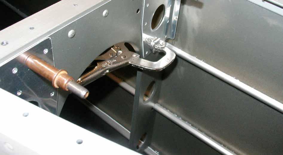
6 Empennage has been removed. The aft deck is held open and out of the way with this simple setup.

7 Doublers clecoed/clamped in place after match drilling.


8 Crack in the upper left corner of F-1010 bulkhead.as seen from the back side looking forward.


9 Crack in the upper left corner of F-1010 bulkhead.as seen from the front side looking aft.


10 F-1010C doubler riveted in place.
SERVICE BULLETIN
 14401 Keil Road NE, Aurora, Oregon, USA 97002 PHONE 503-678-6545 FAX 503-678-6560 www.vansaircraft.com info@vansaircraft.com Service Letters and Bulletins: www.vansaircraft.com/public/service.htm SERVICE
Page: MEMO: In NOTE before Step 5, "Whenever possible, ream using a drill press..." was "Always ream using a drill press...".
 14401 Keil Road NE, Aurora, Oregon, USA 97002 PHONE 503-678-6545 FAX 503-678-6560 www.vansaircraft.com info@vansaircraft.com Service Letters and Bulletins: www.vansaircraft.com/public/service.htm REVISION
REVISION DESCRIPTION:
 14401 Keil Road NE, Aurora, Oregon, USA 97002 PHONE 503-678-6545 FAX 503-678-6560 www.vansaircraft.com info@vansaircraft.com Service Letters and Bulletins: www.vansaircraft.com/public/service.htm REVISION
NEW PRODUCT RELEASE. PRODUCT/KIT NAME: 12 Stabilator Tip Fairing Kit
 14401 Keil Road NE, Aurora, Oregon, USA 97002 PHONE 503-678-6545 FAX 503-678-6560 www.vansaircraft.com info@vansaircraft.com Service Letters and Bulletins: www.vansaircraft.com/public/service.htm NEW PRODUCT
Page: MEMO: In Figure 3, "2X 1 3/32 [27.78 mm]" was "2X 1 3/32 [2.75 mm]"
![Page: MEMO: In Figure 3, 2X 1 3/32 [27.78 mm] was 2X 1 3/32 [2.75 mm]](/thumbs/73/68816766.jpg "Page: MEMO: In Figure 3, 2X 1 3/32 [27.78 mm] was 2X 1 3/32 [2.75 mm]") 14401 Keil Road NE, Aurora, Oregon, USA 97002 PHONE 503-678-6545 FAX 503-678-6560 www.vansaircraft.com info@vansaircraft.com Service Letters and Bulletins: www.vansaircraft.com/public/service.htm REVISION
14401 Keil Road NE, Aurora, Oregon, USA 97002 PHONE 503-678-6545 FAX 503-678-6560 www.vansaircraft.com info@vansaircraft.com Service Letters and Bulletins: www.vansaircraft.com/public/service.htm REVISION
Page: REV 1: In Step 4 "a minimum of 1/16 [1.6 mm] gap" was "an approximately 1/16 [1.6 mm] gap."
![Page: REV 1: In Step 4 a minimum of 1/16 [1.6 mm] gap was an approximately 1/16 [1.6 mm] gap.](/thumbs/72/66557156.jpg "Page: REV 1: In Step 4 a minimum of 1/16 [1.6 mm] gap was an approximately 1/16 [1.6 mm] gap.") 14401 Keil Road NE, Aurora, Oregon, USA 97002 PHONE 503-678-6545 FAX 503-678-6560 www.vansaircraft.com info@vansaircraft.com Service Letters and Bulletins: www.vansaircraft.com/public/service.htm REVISION
14401 Keil Road NE, Aurora, Oregon, USA 97002 PHONE 503-678-6545 FAX 503-678-6560 www.vansaircraft.com info@vansaircraft.com Service Letters and Bulletins: www.vansaircraft.com/public/service.htm REVISION
RV-14 QBF-02 REV 1: In Step 7 (QB), "5-9" was "5-8", and "12-13" was "11-12"
, 5-9 was 5-8, and 12-13 was 11-12") 14401 Keil Road NE, Aurora, Oregon, USA 97002 PHONE 503-678-6545 FAX 503-678-6560 www.vansaircraft.com info@vansaircraft.com Service Letters and Bulletins: www.vansaircraft.com/public/service.htm REVISION
14401 Keil Road NE, Aurora, Oregon, USA 97002 PHONE 503-678-6545 FAX 503-678-6560 www.vansaircraft.com info@vansaircraft.com Service Letters and Bulletins: www.vansaircraft.com/public/service.htm REVISION
Page REV 1: Added "Step 4: Bend the tabs on the wiring channel to match the slant of the F L & -R Tunnel Sides."
 14401 Keil Road NE, Aurora, Oregon, USA 97002 PHONE 503-678-6545 FAX 503-678-6560 www.vansaircraft.com info@vansaircraft.com Service Letters and Bulletins: www.vansaircraft.com/public/service.htm REVISION
Page: 42H-03 REV 1: In Figure 1, replace AN507-6R6 with AN507-6R8
 14401 Keil Road NE, Aurora, Oregon, USA 97002 PHONE 503-678-6545 FAX 503-678-6560 www.vansaircraft.com info@vansaircraft.com Service Letters and Bulletins: www.vansaircraft.com/public/service.htm REVISION
REVISION DESCRIPTION: REV 2: Steps re-written for clarity REV 2: Steps re-written for clarity.
 REVISION DESCRIPTION: 14-04 REV 2: Steps re-written for clarity. 14-05 REV 2: Steps re-written for clarity. SECTION 14: W-1012-L OUTBOARD W-1012-R TRIMMED OUTBOARD S W-1012-L OUTBOARD W-1025B-R FLAP HINGE
REVISION DESCRIPTION:
 REVISION DESCRIPTION: 14401 Keil Road NE, Aurora, Oregon, USA 97002 PHONE 503-678-6545 FAX 503-678-6560 www.vansaircraft.com info@vansaircraft.com Service Letters and Bulletins: www.vansaircraft.com/public/service.htm
Page REV 1: Added 'Step 2: See the "REMOVE THIS TAB, BOTH SIDES" callout near Detail A. Modify four SB375-4 Snap Bushings as shown.
 14401 Keil Road NE, Aurora, Oregon, USA 97002 PHONE 503-678-6545 FAX 503-678-6560 www.vansaircraft.com info@vansaircraft.com Service Letters and Bulletins: www.vansaircraft.com/public/service.htm REVISION
Ayres service bulletin Corporation
 Ayres service bulletin Corporation No. SB-AG-37 P.O. BOX 3090 ONE AYRES WAY ALBANY, GEORGIA 31706-3090 PHONE 229/883-1440 FAX 229/439-9790 Service Bulletin No. SB-AG-37 Page 1 of 12 Approval: FAA Approved
ROLL BAR FRAME 2 PLACES F-1231A-FL ROLL BAR FRAME F-1231C INBOARD F-1231B OUTBOARD ROLL BAR STRAP BAGGAGE BULKHEAD
 SECTION 24iS/U: ROLLOVER F-1231A-FR ROLL BAR FRAME VAN'S AIRCRAFT, INC. F-1231A-AR ROLL BAR FRAME STRUCTURE F-1231E ROLL BAR SPLICE PLATE 2 PLACES F-1232A ROLL BAR BRACE F-01254-R-1 SUPPORT FRAME & F-01207
REVISION DESCRIPTION:
 14401 Keil Road NE, Aurora, Oregon, USA 97002 PHONE 503-678-6545 FAX 503-678-6560 www.vansaircraft.com info@vansaircraft.com Service Letters and Bulletins: www.vansaircraft.com/public/service.htm REVISION
REVISION DESCRIPTION:
 14401 Keil Road NE, Aurora, Oregon, USA 97002 PHONE 503-678-6545 FAX 503-678-6560 www.vansaircraft.com info@vansaircraft.com Service Letters and Bulletins: www.vansaircraft.com/public/service.htm REVISION
Airworthiness Directive Schedule
 Airworthiness Directive Schedule Aeroplanes Cessna 120 26 November 2015 Notes 1. This AD schedule is applicable to Cessna 120 aircraft manufactured under Federal Aviation Administration (FAA) Type Certificate
Page: REV 3: Add drill and tap information to Figure 4 DRILL #3, TAP 1/4-28 BOTH ENDS.
 REVISION DESCRIPTION: 1) Page: 32-03 MEMO: Step 4 should not be bold. Fix WD-1213 callout in Figure 3. Page: 32-04 REV 3: Add drill and tap information to Figure 4 DRILL #3, TAP 1/4-28 BOTH ENDS. Add make
36-01 REV 1: Updated figure to depict current F Bellcrank configuration.
 REVISION DESCRIPTION: 36-01 REV 1: Updated figure to depict current F-00067 Bellcrank configuration. 36-06 REV 1: Updated Figure 1 and Figure 2 to depict current F-00067 Bellcrank configuration. 36-07
Section 75-ZA-3 Fin & Rudder Cable Fairing Installation
 Section 75-ZA-3 Fin & Rudder Cable Fairing Installation This manual has been prepared for installation of the Fin and Fairings. This photo assembly manual is intended as a supplement to the drawings. If
NOTIFICATION
 14401 Keil Road NE, Aurora, Oregon, USA 97002 PHONE 503-678-6545 FAX 503-678-6560 www.vansaircraft.com info@vansaircraft.com Service Letters and Bulletins: www.vansaircraft.com/public/service.htm NOTIFICATION
Page REV 1: In Step 1, added reference to fluid fitting clocking. Added Figure 2 and Figure 3.
 14401 Keil Road NE, Aurora, Oregon, USA 97002 PHONE 503-678-6545 FAX 503-678-6560 www.vansaircraft.com info@vansaircraft.com Service Letters and Bulletins: www.vansaircraft.com/public/service.htm DOCUMENTATION
nd STREET, MENOMINEE, MICHIGAN 49858
 2209 22 nd STREET, MENOMINEE, MICHIGAN 49858 DATE: July 7, 2011 1. SUBJECT: Special Inspections for Agricultural Aircraft 2. MODEL: 480 and 480B Helicopters 3. EFFECTIVITY: Helicopters Equipped with Ag
REVISION DESCRIPTION:
 REVISION DESCRIPTION: 1) Page: 12-03 REV 1: Step 1: and Figure 1: Final-Drill s.b. Match-Drill. Step 4: Updated flox mixture description to match later description (removed "peanut butter-like" description).
SERVICE BULLETIN THIS BULLETIN IS FAA APPROVED FOR ENGINEERING DESIGN
 MOONEY INTERNATIONAL CORPORATION SERVICE BULLETIN 165 Al Mooney Road North Kerrville, Texas 78028 THIS BULLETIN IS FAA APPROVED FOR ENGINEERING DESIGN SERVICE BULLETIN M20-318 Date: June 2, 2014 SUBJECT:
Service Bulletin. SB-GA Issue 1. Subject: Horizontal Stabiliser Attachment Area Inspection and Reinforcement. Applicability: Amendments:
 PO Box 881, Morwell, Victoria 3840, Australia Ph + 61 (0) 3 5172 1200 Fax + 61 (0) 3 5172 1201 www.mahindraaerospace.com Service Bulletin SB-GA8-2016-163 Issue 1 OPTIONAL Subject: Horizontal Stabiliser
1) Page: REV 5: Changed depiction to show added hardware and T-01220
 Page: REV 5: Changed depiction to show added hardware and T-01220") REVISION DESCRIPTION: 1) Page: 37-01 REV 5: Changed depiction to show added hardware and T-01220 Page: 37-02 REV 4: Added Figure 3 depicting Separating the T-01220 Doublers. Figure 4 was Figure 3. Added
REVISION DESCRIPTION: 1) Page: 37-01 REV 5: Changed depiction to show added hardware and T-01220 Page: 37-02 REV 4: Added Figure 3 depicting Separating the T-01220 Doublers. Figure 4 was Figure 3. Added
ZODIAC 601 XL. Trim the outboard corner of the front flange of the center spar 6W4-1. Corner should not touch the side of the cabin floor skin 6B10-1.
 Trim the outboard corner of the front flange of the center spar 6W4-1. Corner should not touch the side of the cabin floor skin 6B10-1. Tape the side skins to the cabin floor skin (area in front of the
Airworthiness Directive Schedule
 Airworthiness Directive Schedule Aeroplanes 22 February 2018 Notes: 1. This AD schedule is applicable to Socata TB9 (Tampico), TB10 (Tobago) and TB20 (Trinidad) aircraft manufactured under EASA Type Certificate
SB-GA Issue 6
 PO Box 881, Morwell, Victoria 3840, Australia Ph + 61 (0) 3 5172 1200 Fax + 61 (0) 3 5172 1201 www.gippsaero.com Service Bulletin Subject: Horizontal Stabiliser Inspection. Applicability: SB-GA8-2002-02
REVISION DESCRIPTION:
 REVISION DESCRIPTION: 14401 Keil Road NE, Aurora, Oregon, USA 97002 PHONE 503-678-6545 FAX 503-678-6560 www.vansaircraft.com info@vansaircraft.com Service Letters and Bulletins: www.vansaircraft.com/public/service.htm
AIRWORTHINESS DIRECTIVE
 AIRWORTHINESS DIRECTIVE On the effective date specified below, and for the reasons set out in the background section, the CASA delegate whose signature appears below revokes Airworthiness Directive (AD)
SECTION 26iS/U: FUEL TANK VAN'S AIRCRAFT, INC. T R OUTBOARD RIB IE-00001X MECHANICAL FUEL GAUGE T R INBOARD RIB T R
 VAN'S AIRCRAFT, INC. SECTION 26iS/U: IE-00001X MECHANICAL FUEL GAUGE T-01222-R OUTBOARD RIB FUEL TANK T-01223-R INBOARD RIB T-01228 RETURN LINE BRACKET T-01224-R INBOARD RIB T-01229 INLET ASSEMBLY T-01223-L
NOTIFICATION
 14401 Keil Road NE, Aurora, Oregon, USA 97002 PHONE 503-678-6545 FAX 503-678-6560 www.vansaircraft.com info@vansaircraft.com Service Letters and Bulletins: www.vansaircraft.com/public/service.htm Date
SECTION 22: FWD LOWER FUSELAGE VAN'S AIRCRAFT, INC F-1257 RUDDER PEDAL SUPPORT CHANNEL, 4 PLACES WD-1204 ENGINE MOUNT BRACKET, 2 PLACES
 SECTION 22: F-1257 RUDDER PEDAL SUPPORT CHANNEL, WD-1204 ENGINE MOUNT BRACKET, VAN'S AIRCRAFT, INC. FWD LOWER F-1201B FIREWALL SHELF FIREWALL BOTTOM FUSELAGE TUNNEL RIB F-1271-R FWD FUSE CORNER SKIN F-1288
"Figure 2: Trim Washer" was "Figure 1: Trim Washers". Page: 40A-06 REV 1: In Step 6, added "Fully torque the nut."
 14401 Keil Road NE, Aurora, Oregon, USA 97002 PHONE 503-678-6545 FAX 503-678-6560 www.vansaircraft.com info@vansaircraft.com Service Letters and Bulletins: www.vansaircraft.com/public/service.htm REVISION
APPLICABLE MODELS PA , PA , PA , PA , PA PA-28R-180, PA-28R-200, PA-28S-160, PA-28S-180
 APPLICABLE MODELS PA-28-14, PA-28-15, PA-28-16, PA-28-18, PA-28-235 PA-28R-18, PA-28R-2, PA-28S-16, PA-28S-18 F L A P, A I L E R O N, F L A P / F U S E L A G E A N D S T A B I L A T O R G A P S E A L S.
12.0 CONTROLS 3/3/2006. Page 1
 Page 1 Page 2 SR3500 Rudder Pedal Parts List ITEM DESCRIPTION PART NUMBER QTY 1 MASTER BRAKE PEDAL RP0015 2 2 SLAVE BRAKE PEDAL RP0016 2 3 PUSH ROD RP0017 4 4 SLAVE BRAKE TORQUE TUBE RP0018 2 5 MASTER
Airworthiness Directive Schedule
 Airworthiness Directive Schedule Aeroplanes 31 March 2011 Notes 1. This AD schedule is applicable to Allied Ag Cat Productions G-164A, G164B and G- 164B-20T aircraft (formerly Schweizer Aircraft Corp.)
Airworthiness Directive Schedule
 Airworthiness Directive Schedule Aeroplanes 30 July 2015 Notes 1. This AD schedule is applicable to De Havilland Canada DHC-2 Beaver MK I aircraft manufactured under Transport Canada Type Certificate Number:
STOL CH F8-2 Front Floor Stiffener. Cut and position the Front Floor Stiffener to the Floor 7F8-7. Back drill through the Floor 7F8-7.
 Wait to drill the ends of the Seat Front 7F11-1 to the L angle on the cabin side at location A-A Ref 7-F-9 until after the Cabin Frame is installed. Ref Fuselage Cabin Frame, Section 10, page 11. NOTE:
SERVICE LETTER NUMBER 173
 By: RCG Approved: JRS Date: 8/16/2017 Rev: A SERVICE LETTER NUMBER 173 10000 BULKHEAD 7 STIFFENER ADDITION Aircraft Makes/Model(s): AT-802 AT-802A Float Model(s): 10000A Note(s): Mandatory Compliance Service
Airworthiness Directive Schedule
 Airworthiness Directive Schedule Aeroplanes 26 October 2000 The date above indicates the amendment date of this schedule. New or amended ADs are shown with an asterisk * Contents DCA/VIC/101 Nose Leg Shear
FLAP, AILERON, FLAP/FUSELAGE AND STABILATOR GAP SEAL INSTALLATION AND MAINTENANCE MANUAL
 FLAP, AILERON, FLAP/FUSELAGE AND STABILATOR GAP SEAL INSTALLATION AND MAINTENANCE MANUAL Aircraft Eligibility: Piper PA-28-151, PA-28-161, PA-28-181, PA-28-201T, PA-28-236, PA- 28R-201, PA-28R-201T, PA-28RT-201,
SERVICE INSTRUCTION SI Revision 1
 SERVICE INSTRUCTION SI-25-02 Revision 1 TITLE: Aft Seats Inertia Reel Harness Installation (Mod 1229) SUBJECT / REASON / DESCRIPTION: The FBA-2C1 and FBA-2C2 aircraft are equipped with three individual
TECHNICAL BULLETIN May 2013 Revision A, 11 July 2013 SUBJECT: TAIL ROTOR GEARBOX 3 PIECE FAIRING, MODIFICATION OF
 TECHNICAL BULLETIN 206-13-205 24 May 2013 Revision A, 11 July 2013 MODEL AFFECTED: 206A/B SUBJECT: TAIL ROTOR GEARBOX 3 PIECE FAIRING, MODIFICATION OF HELICOPTERS AFFECTED: Serial number 004 through 1251.
GlaStar and Sportsman Service Bulletin 67
 GlaStar and Subject: Applicability: Issue: Compliance Time: Elevator counterweights All GlaStar and Aircraft Counterweight attachment to elevator end rib At or before next condition inspection Discussion
F-1202D-L PANEL ATTACH STRIP F L UPPER FWD FUSELAGE SKIN RIB F CABIN EGRESS HANDLE F-1240B COVER PLATE
 SECTION 29iS/U: F-1202D-L PANEL ATTACH STRIP F-01240-1 UPPER FORWARD FUSELAGE SKIN (SHOWN TRANSPARENT) VAN'S AIRCRAFT, INC. FWD UPPER FUSELAGE F-00078 CABIN EGRESS HANDLE F-00077-L UPPER FWD FUSELAGE SKIN
Seabee Annual Inspection Procedures
 Procedures Due to the wide variety of Seabee s flying out there, these procedures should be modified to fit YOUR Seabee. Make sure that all AD s are complied with as well as any required Service Bulletins
Airworthiness Directive Schedule
 Airworthiness Directive Schedule Aeroplanes 29 May 2008 Notes 1. This AD schedule is applicable to aircraft (formally Taylorcraft 2000 LLC and Harvey & Vera Patrick Foundation Inc. etc.), manufactured
Airworthiness Directive Schedule
 Airworthiness Directive Schedule Aeroplanes 27 October 2011 Notes 1. This AD schedule is applicable to aircraft manufactured under Federal Aviation Administration (FAA) Type Certificate No. A18SO. 2. The
SERVICE KIT thru , 631, 634, 675 R thru R F thru F FR thru FR
 TITLE SEAT BELT AND SHOULDER HARNESS KIT INSTALLATION EFFECTIVITY MODEL SERIES SERIAL NUMBERS 182 33000 thru 18268368 182 613, 631, 634, 675 R182 R18200001 thru R18201973 F182 F18200001 thru F18200169
TEMPORARY REVISION NUMBER
 TEMPORARY REVISION NUMBER 7 DATED 1 DECEMBER 2011 MANUAL TITLE MANUAL NUMBER - PAPER COPY TEMPORARY REVISION NUMBER Model 188 & T188 Series 1966 Thru 1984 Service Manual D2054-1-13 D2054-1TR7 MANUAL DATE
TECHNICAL BULLETIN May 2013 SUBJECT: TAIL ROTOR GEARBOX 3 PIECE FAIRING, MODIFICATION OF
 TECHNICAL BULLETIN 206-13-205 24 May 2013 MODEL AFFECTED: 206A/B SUBJECT: TAIL ROTOR GEARBOX 3 PIECE FAIRING, MODIFICATION OF HELICOPTERS AFFECTED: Serial number 004 through 1251. COMPLIANCE: At customer
Airworthiness Directive Schedule
 Airworthiness Directive Schedule Aeroplanes 27 July 2006 The date above indicates the amendment date of this schedule. New or amended ADs are shown with an asterisk * Contents DCA/B99/1 Wing Attachment
FUSELAGE CABIN ASSEMBLY
 SECTION 3 Cabin Frame Ref Dwg 8FC-3 The Top of the Cabin Frame is level The distance between the front and rear wing attachment to fit the wings SECTION 3 - Page 1 of 10 CABIN FRAME 8F18-1 The TOP TUBES
Section 75-FA-4. Forward Fuselage
 Section 75-FA-4 This manual has been prepared for assembly of the forward fuselage skins supplied with match drilled parts. This photo assembly manual is intended as a supplement to the drawings. If there
The engine cowling installation and firewall should be inspected and modified as specified in this Service Bulletin.
 Single Engine Service Bulletin August 25, 2008 TITLE ENGINE COWLING ALIGNMENT INSPECTION AND MODIFICATION EFFECTIVITY Model Serial Numbers 172R 17280001 thru 17280724 172S 172S8001 thru 172S8201 REASON
Airworthiness Directive Schedule
 Airworthiness Directive Schedule Aeroplanes 30 October 2014 Notes: 1. This AD schedule is applicable to aircraft listed on the following European Aviation Safety Agency (EASA) and Registro Aeronautico
SERVICE LETTER. SERIAL NUMBERS 210 & T thru P thru P
 TITLE SERVICE LETTER WINGS - LOWER MAIN SPAR CAP INSPECTION EFFECTIVITY REASON MODEL SERIAL NUMBERS 210 & T210 21058819 thru 21065009 P210 P2100001 thru P2100874 Reports have been received of cracks found
FAA approval has been obtained on technical data in this publication that affects airplane type design.
 Single Engine Service Bulletin January 28, 2008 TITLE ENGINE COWLING ALIGNMENT INSPECTION AND MODIFICATION EFFECTIVITY Model Serial Numbers 172R 17280725 thru 17281262 172S 172S8202 thru 172S10006 REASON
REVISION DESCRIPTION:
 14401 Keil Road NE, Aurora, Oregon, USA 97002 PHONE 503-678-6545 FAX 503-678-6560 www.vansaircraft.com info@vansaircraft.com Service Letters and Bulletins: www.vansaircraft.com/public/service.htm REVISION
BMAA Defect Alert #0057: Light Sport Aircraft Ltd SB19 Cracking of the Rear Fuselage Bulkhead
 Dated: 12/07/2016 BMAA Defect Alert #0057: Light Sport Aircraft Ltd SB19 Cracking of the Rear Fuselage Bulkhead Light Sport Aircraft Ltd SB19 The SB regards inspecting for cracks on the rear Fuselage bulkhead
Single Engine. Service Bulletin TITLE ELEVATOR TRIM TAB ACTUATOR ASSEMBLY INSPECTION EFFECTIVITY. Group A airplanes: Serial Numbers
 Single Engine Service Bulletin March 12, 2007 TITLE ELEVATOR TRIM TAB ACTUATOR ASSEMBLY INSPECTION EFFECTIVITY Group A airplanes: Model Serial Numbers 172R 17281353 thru 17281364, 17281369 thru 17281372
2000 SERIES SPEEDBRAKE INSTALLATION MANUAL MOONEY M20 SERIES & M22 STC NO. SA4342NM NOTE: READ THESE DIRECTIONS BEFORE STARTING!
 INSTALLATION REPORT NO. 08059 Serial Number PRECISE FLIGHT, INC. 800-547-2558 2000 SERIES SPEEDBRAKE INSTALLATION MANUAL MOONEY M20 SERIES & M22 NOTE: READ THESE DIRECTIONS BEFORE STARTING! THIS DOCUMENT
1154B. Piper Aircraft, Inc Piper Drive Vero Beach, Florida, U.S.A Date: March 28, 2007 (S)
") TM 1154B Piper Aircraft, Inc. 2926 Piper Drive Vero Beach, Florida, U.S.A. 32960 Date: March 28, 2007 (S) SB 1154B supersedes SB 1154A and SB 1154. SB 1154B shortens the repetitive inspection requirement
TM 1154B Piper Aircraft, Inc. 2926 Piper Drive Vero Beach, Florida, U.S.A. 32960 Date: March 28, 2007 (S) SB 1154B supersedes SB 1154A and SB 1154. SB 1154B shortens the repetitive inspection requirement
FIGURE 2: ADDING FITTINGS TO BRAKE ASSEMBLY (RIGHT SHOWN) FIGURE 1: ATTACHING AND ALIGNING THE MAIN GEAR AXLES
 FIGURE 1: ATTACHING AND ALIGNING THE MAIN GEAR AXLES") VAN'S AIRCRAFT, INC. Step 2: Apply pipe thread sealant and attach the fluid fittings to the brake as shown in Figure 2. Note that the brakes should mirror each other when installed. Step 1: Bolt the main
VAN'S AIRCRAFT, INC. Step 2: Apply pipe thread sealant and attach the fluid fittings to the brake as shown in Figure 2. Note that the brakes should mirror each other when installed. Step 1: Bolt the main
PARAVION TECHNOLOGY, INC AIRWAY AVENUE FORT COLLINS, COLORADO REPORT NO. PR-206H-900M CABIN HEATER SYSTEM INSTALLATION INSTRUCTIONS
 PARAVION TECHNOLOGY, INC. 2001 AIRWAY AVENUE FORT COLLINS, COLORADO 80524 REPORT NO. CABIN HEATER SYSTEM INSTALLATION INSTRUCTIONS BELL 206A/B HELICOPTERS Page i PR- Rev. P, 04/06/09 REVISIONS REV. DATE
LAA TYPE ACCEPTANCE DATA SHEET TADS 303 VANS RV-8. Issue 8 Additional service bulletins added, as follows SB , SB
 Issue 8 Additional service bulletins added, as follows 12.02.08 SB 07-11-09, SB 07-4-12 1. UK contact There is no UK agent. Contact Vans direct: Van s Aircraft Inc, PO Box 160, North Plains, Oregon, 97133.
SERVICE LETTER. Multi-engine TITLE NACELLES/PYLONS - NACELLE FITTING INSPECTION EFFECTIVITY
 TITLE NACELLES/PYLONS - NACELLE FITTING INSPECTION EFFECTIVITY REASON MODEL 402C 414A SERIAL NUMBERS 402C0001 thru 402C1020 that have SK402-47 - Lower Front Wing Spar Cap Inspection/Modification (Original
PARAVION TECHNOLOGY, INC AIRWAY AVENUE FORT COLLINS, COLORADO 80524
 Revision F PARAVION TECHNOLOGY, INC. 2001 AIRWAY AVENUE FORT COLLINS, COLORADO 80524 REPORT NO. INSTALLATION INSTRUCTIONS BELL MODEL 407 SERIES BLEED-AIR CABIN HEATER Page i Rev. F, 04/06/09 REVISIONS
Comanche Tail Problems and Cures
 Comanche Tail Problems and Cures As our Comanche fleet ages our maintenance requirements will continue to change. We re only one year away from Comanches having their 50 th birthday. The newest Comanche
aileron rib inspection
 Piper Aircraft, Inc. 2926 Piper Drive Vero Beach, Florida, U.S.A. 32960 SERVICE NO. 1216B BULLETIN PIPER CONSIDERS COMPLIANCE MANDATORY Date: September 5, 2012 (S) Service Bulletin 1216B supersedes Service
TEMPORARY REVISION NUMBER
 TEMPORARY REVISION NUMBER 8 DATED 1 DECEMBER 2011 MANUAL TITLE MANUAL NUMBER - PAPER COPY TEMPORARY REVISION NUMBER 1978 Thru 1986 Model R182 & TR182 Service Manual D2069-3-13 D2069-3TR8 MANUAL DATE 15
Models AA-5, AA-5A & AA-5B Annual or 100-hour Inspection
 Models AA-5, AA-5A & AA-5B Registration Number Serial Number Hours Registered Owner(s) Street Address City State/ Postal Code Provence Inspector Signature License No. Date Airport/City State/ Provence
Airworthiness Directive Schedule
 Airworthiness Directive Schedule Helicopters 27 October 2011 Notes 1. This AD schedule is applicable to Airbus Helicopters SA 315B (Lama) and SA 316C (Alouette III) helicopters (formerly Eurocopter, Eurocopter
12NPR Reason For Revision
 12NPR 04-03-14-1 Reason For Revision 1) RV-12 SkyView Touch Avionics Kit 2) RV-12 SkyView AP-Knob Panels Kit (58) 3) Add instructions for installation of F-00062. 4) Allow use of lighter springs on RV-12
performance S T O L Installation Instructions Manual No. PSTOL-013 Double Slotted Flaps for Piper PA-18 Series Aircraft
 performance S T O L Installation Instructions Manual No. PSTOL-013 Double Slotted Flaps for Piper PA-18 Series Aircraft 1 This Page Intentionally Left Blank 2 Record of Revisions Rev Level Date Page By
Airworthiness Directive Schedule
 Airworthiness Directive Schedule Aeroplane 25 August 2016 Notes 1. This AD schedule is applicable to Diamond DA 42 aircraft listed on European Aviation Safety Agency (EASA) Type Certificate No. A.005.
Nose Wheel Leg Attachment Angles - Replacement
 AD/VAT/1 Nose Wheel Leg Attachment Angles - Replacement 12/62 Applicability: Victa Airtourer 100 with S/Nos. 1 to 8. Document: Victa SB No. 3. Compliance: Before 1 September 1971. AD/VAT/2 Rudder Pedal
GlaStar / Sportsman Service Bulletin 64- MANDATORY
 GlaStar / MANDATORY Note: Subject: Applicability: This service bulletin supersedes 49. The service bulletin applicability was updated to include kits. No other changes were made Inspection of welded cage
HARTZELL PROPELLER INC. SERVICE BULLETIN TRANSMITTAL SHEET SERVICE BULLETIN HC-SB Propeller - Propeller Installation.
 TRANSMITTAL SHEET March 16, 2006 This page transmits Revision 1 to Service Bulletin. Original, dated Revision 1, dated Mar 16/06 FAA approval has been obtained on technical data in this publication that
Cal Pacific Airmotive, Inc.
 Cal Pacific Airmotive, Inc. Title: Inspection of Flight Control System Mandatory Service Bulletin North American Aviation P-51B, P-51C, P-51D, P-51K, F-51D, F-51K S.B. No. P51-001 Revision: 0 Issue Date
SERVICE BULLETIN. Fuselage Tail Cone Damage
 Fuselage Tail Cone Damage It has come to our attention that a number of Sportsman tailwheel installations have resulted in crushed and/or delaminated fuselage laminates near the aft tailwheel bracket.
EXPRESS ASSEMBLY MANUAL SECTION 3 F5-RG/FT WING ASSEMBLY. Procedure 3.050A INSTALLATION OF AILERON TORQUE TUBE ASSEMBLY
 Procedure 3.050A INSTALLATION OF AILERON TORQUE TUBE ASSEMBLY In this procedure The aileron torque tube will be assembled and installed in the wing. Part Number Description Quantity 111-24-050 Torque Tube,
PARAVION TECHNOLOGY, INC AIRWAY AVENUE FT. COLLINS, COLORADO 80524
 [Rev. 5, 11/07/07] PARAVION TECHNOLOGY, INC. 2001 AIRWAY AVENUE FT. COLLINS, COLORADO 80524 INSTRUCTIONS FOR CONTINUED AIRWORTHINESS 407H-120M BLEED-AIR CABIN HEATER INSTALLATION BELL MODEL 407 HELICOPTERS
SECTION 35iS/U: LANDING GEAR & ENGINE MOUNT
 WD-1221 ENGINE MOUNT STANDOFF SECTION 35iS/U: LANDING GEAR & ENGINE MOUNT U-01203E-1 INBOARD DOUBLER PLATE U-01203B-1 INBOARD WEAR PLATE U-01203C-1 BEARING PLATE U-01203-2 (U-01203-1 SHOWN) INBOARD MAIN
Airworthiness Directive Schedule
 Airworthiness Directive Schedule 29 August 2013 Notes 1. This AD schedule is applicable to Hawker Beechcraft Corporation (formally Raytheon Aircraft Company and Beech Aircraft Company), manufactured under
STOL CH 701. STOL CH701 cabin. Top view: Tunnel 7F11-4 between the Seats. STOL CH701 Seats
 CH701 cabin Top view: Tunnel 7F11-4 between the Seats. CH701 Seats CHECK: If the Gusset 7F11-7 is supplied bent; hen it is best to install the Gusset before the Seat 7F16-1. Otherwise, install the Seat
LAA TYPE ACCEPTANCE DATA SHEET TADS 304 JODEL 1050-M1. Issue 2 New format. Change of take-off weight. Dated 16/01/2017 JV
 Issue 2 New format. Change of take-off weight. Dated 16/01/2017 JV These TADS are intended as a summary of available information about the type and should be used during the build, operation and permit
P.O. Box 3149 Albany, GA Phone (229) Fax (229) March 7, 2006 FLAP CONTROL TORQUE SHAFT REPLACEMENT
 Fax (229) March 7, 2006 FLAP CONTROL TORQUE SHAFT REPLACEMENT") THRUSH AIRCRAFT, INC. P.O. Box 3149 Albany, GA 31706-3149 Phone (229) 883-1440 Fax (229) 436-4856 SERVICE BULLETIN March 7, 2006 No. SB-AG-48 FLAP CONTROL TORQUE SHAFT REPLACEMENT MODELS AFFECTED: Aircraft
THRUSH AIRCRAFT, INC. P.O. Box 3149 Albany, GA 31706-3149 Phone (229) 883-1440 Fax (229) 436-4856 SERVICE BULLETIN March 7, 2006 No. SB-AG-48 FLAP CONTROL TORQUE SHAFT REPLACEMENT MODELS AFFECTED: Aircraft
Airworthiness Directive Schedule
 Airworthiness Directive Schedule Aeroplane Diamond DA42 25 January 2018 Notes: 1. This AD schedule is applicable to Diamond DA 42 aircraft listed in European Aviation Safety Agency (EASA) Type Certificate
*MANDATORY SERVICE BULLETIN*
 NUMBER: SB-022 REVISION: B DATE: 10/30/2009 SUBJECT: PITOT STATIC SYSTEM; MANDATORY MODIFICATION KODIAK MANDATORY SERVICE BULLETIN *MANDATORY SERVICE BULLETIN* SUMMARY *MANDATORY SERVICE BULLETIN* RECURRENT
SERVICE DIRECTIVE BULLETIN
 SERVICE DIRECTIVE BULLETIN DATE: February 15, 2019 Page 1 of 11 1. SUBJECT: Main Rotor Push-Pull Rod Inspection 2. MODEL: F-28, F-28A, 280, F-28C, F-28C-2, F-28C-2R, 280C, F-28F, F-28F-R, 280F, and 280FX
Pitch Control and Trim
 Pitch Control and Trim GENERAL 27-30: PITCH CONTROL AND TRIM. General This section describes that portion of the flight control system which controls the position and movement of the elevator. This includes
CHAPTER 15 FURNISHINGS. Section Title Page
 CHAPTER 15 FURNISHINGS Section Title Page 15.000 Description..................................... 15.1 15.100 Seat Harnesses................................... 15.3 15.110 Four-Point Harness Assembly.................
2000 SERIES SPEEDBRAKE INSTALLATION MANUAL STC NO. SA2602NM
 INSTALLATION REPORT NO. 08062 Serial Number PRECISE FLIGHT, INC. 800-547-2558 2000 SERIES SPEEDBRAKE INSTALLATION MANUAL CESSNA 210G, T210G, 210H, 210J, 210K, T210J, 210L, T210L, 210M, T210M, 210N, P210N,
AA-5 SERIES MAINTENANCE MANUAL MODELS AA-5, AA-SA & AA-5B HOUR INSPECTION PROCEDURE ANNUAL OR 100 HOUR INSPECTION PROCEDURE GUIDELINE
 MODELS AA-5, AA-SA & AA-5B ANNUAL OR 100 - HOUR INSPECTION PROCEDURE ANNUAL OR 100 HOUR INSPECTION PROCEDURE GUIDELINE FAR 43 15 (C) (1) states: Each person performing an annual or 100 hour inspection
Zenair Europe Service Letter
 Zenair Europe Service Letter FLAP STOPS S.L. Number: ZE-2009-06 Date of issue: November 25, 2009 Subject: Affected Models: This Service Letter (SL) has been issued by Zenair SARL (Europe). Aileron counter-balance
Airworthiness Directive Schedule
 Airworthiness Directive Schedule Gliders Glasflugel and HPH Glasflugel 26 July 2018 Notes: 1. This AD schedule is applicable to the following Glasflugel gliders manufactured under EASA Type Certificate