Commercial & Industrial Ventilation Complete Line of Sustainable Products
|
|
|
- Jason Ezra Sutton
- 5 years ago
- Views:
Transcription


1 ommercia l Kitchen Ventilation ommercial & Industrial Ventilation omplete Line of Sustainable Products (fax)


.")
2 ontents entrifugal Upblast xhaust Fans N-F elt rive N-HPF High Pressure elt rive U-HF irect rive entrifugal ownblast xhaust Fans -F elt rive R-HF Radial irect rive entrifugal Utility Sets HR High Velocity Restaurant uty elt rive I-RM Restaurant uty elt rive I- General uty elt rive IRM elt rive USI Utility Set, Restaurant uty irect Fired Heated Make-Up ir Series Modular Roof Mount Inline ompact Indirect Fired Heated Make-Up ir I Series Modular Roof Mount & Inline lectric Heated Make-Up ir Series Modular Roof Mount & Inline Industrial Heated Make-Up ir H irect Fired Horizontal Non-Recirculating Unit H-M irect Fired Horizontal Recirculating Unit V irect Fired Vertical Non-Recirculating Unit V-M irect Fired Vertical Recirculating Unit eiling and Inline xhaust Fans ISQ elt rive ISQ irect rive F- eiling and Inline Series Inline uct lower Wall Mount xhaust Fans PRSM Integral Shutter irect rive Roof Mount xhaust Fans R-F ownblast irect rive ccessories for Power Ventilators ampers & urbs Propeller Make-Up ir MU-F Roof or Wall Mount Gravity Hood MU-F conomy Make-Up ir onfiguring Modular Make-Up ir Modular Make-Up ir Systems Untempered Make-Up ir NSU Standard Rooftop Series Modular Rooftop Inline Series xhaust Hood Systems Low Proximity Wall anopy NI xhaust Only Island N- xhaust Hood w/ Make-Up ir N- xhaust Only SN- Low eiling Hood w/make-up ir Self-leaning Hood System Heat & ondensate Vent Hoods VH xhaust Only lectrical ontrols T M nergy Management System Fire Systems OR Protection Options & ccessories -PSP (/ Perforated Supply Plenum) PSP (Perforated Supply Plenum) High fficiency Stainless Steel affle Filter aptrate Solo Filter aptrate ombo Filter dditional quipment Pollution ontrol Unit Utility istribution System Factory Welded Grease uct Systems
3 3 N-F elt rive entrifugal Upblast Fans W HT F Grease rain NF-UL705 RV.# 08/0/003 R RO Features & enefits omplete range of motors available to meet specific application needs Heavy duty construction, durable and weather resistant Non-overloading backward inclined wheels, blades and inlets fabricated from 3003-H14 aluminum Wall mount applications; units up to 4 nominal wheel can be wall mounted Forced fresh air through the motor compartment cools motor and ensures long motor life Quick release latches allow for easy access to motor compartment Variable pitch motor pulley allows for field adjustment and system balancing High efficiency combined with low tip speeds result in quiet operation xternal disconnect switch Fully welded, leak-proof grease drain Vibration isolation Vented urb 0 Gauge Steel onstruction 3" Flange Options Performance Gravity amper (UL 705 only) Motorized amper (UL 705 only) Wall Mount Sleeve ird Screen (UL 705 only) Grease ollection ox Roof urb (vented & non vented) ase Hinging Kit or Hinged Sub ase (for NFP96 compliance) MOL HT W F R RO N8F 5 1/4 7 1/ / 18 1/ 1 1/8 NF 7 1/4 30 1/ / 0 1 1/ 13 1/4 N14F 30 1/ 33 3/4 4 3/ /8 N16F 33 3/4 39 3/ / 0 3 1/ N18F 33 3/8 38 7/ / 0 N4F 37 1/ 43 3/ / ertifications N30F /4 40 N36F 49 1/ / aptiveire certifies that Models N8F thru N36F shown herein are licensed to bear the M seal. The ratings shown are based on tests & procedures performed in accordance with M Publication 11 and Publication 311, and comply with the requirements of the M ertified Ratings Program. Models N8F thru N36F are TL Listed and comply with UL705 (electrical) and UL Standards and S Std.., No Weight (lbs) 5 amper (lbs) / / /8 3 7/ / / / 30 3/ / Motor vailability Motor Frame Single Phase Three Phase HP Open Speed Open 1/4 na na 1/3 na 1/ 3/4 Largest Model Frame na N8F 56 na na NF 56 N14F 145T N16F 145T 1 N18F 145T 1 1/ na N4F 18T na N30F 18T 3 na N36F 13T 5 na na 7 1/ na na Speed
4 4 HP (rake Horsepower): The actual power developed by a motor as measured by the force applied to a shaft or flywheel. Performance 0.00 sp 0.5 sp 0.50 sp 0.75 sp 1.00 sp 1.5 sp 1.50 sp 1.75 sp.00 sp MOL N8F 800 N8F / / / / / N8F / / / / / / / / 0.43 N8F / / / / / / 0.40 N8F N8F 1800 NF 100 NF / / / / 0.46 NF / / / / / / / / 0.48 NF NF / / / / / / / / 0.50 NF NF 400 N14F 1600 N14F 1800 N14F N14F N14F / / / / / / / / 1.00 N14F / / / / / / / / / / / / / / / 0.94 N14F N14F / / / / / / / / / / / / / / 0.98 N14F N14F / / / / / / / / / / / / / 0.96 N14F N14F 3800 N16F 1500 N16F 000 N16F 500 N16F 3000 N16F / / / / / / / / / / / / / / / / / / / N16F / / / / / / / / / / / 1.80 N16F / / / / / / / / / / 1.83 N16F N16F 5500 N18F 00 N18F 700 N18F 300 N18F / / / / / / / / / / / / / / / / / / / / 1.71 N18F / / / / / / / / / 1.93 N18F / / / / / / / / 1.9 N18F / / / / / / / / / / / / / / / / / / / / / / / / / / / / / / / / / / / / / / / / / 0.85 Performance shown is for installation Type ; Free Inlet, Free Outlet. Power Rating (HP) does not include rive Losses. Performance Ratings do not include the effects of appurtenances in the air stream. The Sound Ratings shown are loudness values in fan sones at 5 ft. (1.5m) in a hemispherical free field calculated per M Standards 301. Values shown are for installation Type ; Free inlet fan sone levels. The M ertified Ratings Sound Seal applies to Sone Ratings only.
5 5 HP (rake Horsepower): The actual power developed by a motor as measured by the force applied to a shaft or flywheel. Performance 0.00 sp 0.5 sp 0.50 sp 0.75 sp 1.00 sp 1.5 sp 1.50 sp 1.75 sp.00 sp MOL Son e/hp N18F / / / / / 1.8 N18F N18F 6700 N4F 3500 N4F 4500 N4F 5500 N4F 6500 N4F / / / /.11 0 / / / / / / / / / 4.83 N4F / / / / / / / / / / / / / / / / / / / / / / / / / / 4.33 N4F / / / / / / / / / / / 4.34 N4F N4F N30F 5000 N30F 6000 N30F 7000 N30F 8000 N30F / / / / / / / / / / / / 4.8 N30F / / / / / / / / / / / / 4.5 N30F / / / / / / / / / / N30F / / / / / / / / / / / / 4.7 N30F N30F N36F 000 N36F 1000 N36F / / / / / / / / / / 7.49 N36F / / / / / / / / / 6.96 N36F 46.5 / / / / / / / / / / / / / / / / 6.5 N36F 35 1 / / / / / / / / / / / / / / / / / / / / / / / / / / / Performance shown is for installation Type ; Free Inlet, Free Outlet. Power Rating (HP) does not include rive Losses. Performance Ratings do not include the effects of appurtenances in the air stream. The Sound Ratings shown are loudness values in fan sones at 5 ft. (1.5m) in a hemispherical free field calculated per M Standards 301. Values shown are for installation Type ; Free inlet fan sone levels. The M ertified Ratings Sound Seal applies to Sone Ratings only.
6 6
7 7 N-HPF elt rive-high Pressure entrifugal Upblast Fans W HT F Grease rain NF-UL705 08/0/003 RV.# R RO Features & enefits omplete range of motors available to meet specific application needs Heavy duty construction, durable and weather resistant Non-overloading backward inclined wheels, blades and inlets fabricated from 3003-H14 aluminum Wall mount applications; units up to 4 nominal wheel can be wall mounted Forced fresh air through the motor compartment cools motor and ensures long motor life Quick release latches allow for easy access to motor compartment Variable pitch motor pulley allows for field adjustment and system balancing High efficiency combined with low tip speeds result in quiet operation xternal disconnect switch Fully welded, leak-proof grease drain Vibration isolation Options Gravity amper (UL 705 only) Motorized amper (UL 705 only) Wall Mount Sleeve ird Screen (UL 705 only) Grease ollection ox Roof urb (vented & non vented) ase Hinging Kit or Hinged Sub ase (for NFP96 compliance) ertifications Vented urb 0 Gauge Steel onstruction 3" Flange Measurements MOL HT W F R RO N14HPF 30 1/ 33 3/4 4 3/ /8 0 Weight (lbs) 140 amper (lbs) 19 N16HPF 33 3/4 39 3/ / 0 3 1/ 16 1/ N18HPF 33 3/8 38 7/ / 0 9 1/ N4HPF 37 1/ 43 3/ / /8 3 7/ N30HPF / / / Motor vailability aptiveire certifies that Models N14HPF thru N30HPF shown herein are licensed to bear the M seal. The ratings shown are based on tests & procedures performed in accordance with M Publication 11 and Publication 311, and comply with the requirements of the M ertified Ratings Program. Models N14HPF thru N30HPF are TL Listed and comply with UL705 (electrical) and UL Standards and S Std.., No Motor Frame Single Phase Three Phase HP Open Speed Open Speed Model Largest Frame 1/4 na na na N8HPF 56 1/3 na na na NHPF 56 1/ N14HPF 145T 3/4 N16HPF 145T 1 N18HPF 145T 1 1/ na N4HPF 18T na N30HPF 18T 3 na N36HPF 13T 5 na na 7 1/ na na
8 8 HP (rake Horsepower): The actual power developed by a motor as measured by the force applied to a shaft or flywheel. Performance MOL N8HPHPF N8HPHPF 00 N8HPHPF 100 N8HPHPF 1400 N8HPHPF 1600 N8HPHPF 1800 NHPF 100 NHPF 1400 NHPF 1600 NHPF 1800 NHPF 000 NHPF 00 NHPF 400 N14HPF 1600 N14HPF 1800 N14HPF 000 N14HPF 00 N14HPF 400 N14HPF 600 N14HPF 800 N14HPF 3000 N14HPF 300 N14HPF 3400 N14HPF 3600 N14HPF 3800 N16HPF 1500 N16HPF 000 N16HPF 500 N16HPF 3000 N16HPF 3500 N16HPF 4000 N16HPF 4500 N16HPF 5000 N16HPF 5500 N18HPF 00 N18HPF 700 N18HPF 300 N18HPF 3700 N18HPF 400 N18HPF 4700 N18HPF 500 N18HPF 5700 N18HPF 600 N18HPF sp 0.5 sp 0.50 sp 0.75 sp 1.00 sp 1.5 sp 1.50 sp 1.75 sp.00 sp / / / / / / / / / / / / / / / / / / / / / / / / / / / / / / / / / / / / / / / / / / / / / / / / / / / / / / / / / / / / / / / / / / / / / / / / / / / / / / / / / / / / / / / / / / / / / / / / / / / / / / / / / / / / / / / / / / / / / / / / / / / / / / / / / / / / / / / / / / / / / / / / / / / / / / / / / / / / / / / / / / / / / / / / / / / / / / / / / / / / / / / / / / / / / / / / / / / / / / / / / / / / / / / / / / / / / / / 1.9 Performance shown is for installation Type ; Free Inlet, Free Outlet. Power Rating (HP) does not include rive Losses. Performance Ratings do not include the effects of appurtenances in the air stream. The Sound Ratings shown are loudness values in fan sones at 5 ft. (1.5m) in a hemispherical free field calculated per M Standards 301. Values shown are for installation Type ; Free inlet fan sone levels. The M ertified Ratings Sound Seal applies to Sone Ratings only.
9 9 U-HF irect rive entrifugal Upblast Fans W HT F Grease rain* NF-UL705 RV.# 08/0/003 Note: Grease drain not *Note: installed Grease on rain Not UHF Installed On UHF R RO Features & enefits ompletely enclosed drive compartment protects motor from airborne contaminants Forced fresh air through the motor compartment cools motor and ensures long motor life Variable speed control Non-overloading backward inclined wheels, blades and inlets fabricated from 3003-H14 aluminum ll sizes can be wall mounted Quick release latches allow for easy access to motor compartment xternal disconnect switch Fully welded leak proof grease drain Vented urb 0 Gauge Steel onstruction 3" Flange Options Gravity amper (UL705 only) Motorized amper (UL705 only) Wall Mount Sleeve Roof urb (Vented and Non-vented) Grease ollection ox (size 1 and larger) ird Screen (UL705 only) ase Hinging Kit or Hinged Sub ase (for NFP96 compliance) Measurements 13 Weight (lbs) 30 amper (lbs) / / 1 1/ / 13 1/ / / MOL HT W F R RO UHF 14 1/ 17 3/ / 1 9 1/ 8 1/8 U1HF / /8 U5HF 5 1/4 5 1/ / / 1 1/8 aptiveire certifies that Models UHF thru U85HF shown herein are licensed to bear the M seal. The ratings shown are based on tests & procedures in accordance with M Publication 11 and Publication 311, and comply with the requirements of the M ertified Ratings Program. U30HF 5 1/4 5 1/ / / U33HF 5 1/4 5 1/ / 1 U50HF 7 1/4 8 7/ / U75HF 30 1/ 31 7/8 4 3/4 U85HF 30 1/ 31 7/8 4 3/4 Models UHF thru U85HF are TL Listed and comply with UL 705 (electrical) and UL Standards and S Std.., No Motor vailability ertifications Single Phase Three Phase HP 1 Speed Speed ontrol 1 Speed VF* UHF na na U1HF na na U5HF na na U30HF na na U33HF U50HF U75HF na na U85HF Note: S peed ontrols are not shipped with three phase fans. Variable Frequency devices are required to adjust three phase motor speed (optional).
10 HP (rake Horsepower): The actual power developed by a motor as measured by the force applied to a shaft or flywheel. Performance 0.00 sp 0.15 sp 0.5 sp sp 0.50 sp 0.65 sp 0.75 sp 1.00 sp 1.5 sp Motor HP / / / / / / / / / / / / / / / / / / / / / / / / / / / / / / / / / / / / / / / / / / / / / / / / / / / / / / / / / / / / / / / / / / / / / / / / / / / / / / / / / / / / / / / / / / / / / / / / / / / / / / / / / / / / / / / / / / / / / / / / / / / / / / / / / / / / / / / / / / / / / / / / / / / / / / / / / / / / / / / / / / / / / / / / / / / / / / / / / / / / / / / / / / / / / / / / / / / / / / / / / / / / 0.74 MOL Tip Speed UHF UHF UHF UHF UHF UHF UHF U1HF U1HF U1HF U1HF U1HF U1HF U1HF U5HF U5HF U5HF U5HF U30HF U30HF U30HF U30HF U30HF U30HF U30HF U33HF U33HF U33HF U33HF U33HF U33HF U33HF U50HF U50HF U50HF U50HF U50HF U50HF U50HF U75HF U75HF U75HF U75HF U75HF / / / / / / / / / / / / / / / / / / / / / / / / / / / / / / / / / / / / / / / / / / / / / / / / / / / / / / / / / / / / / / / / / 0.74
11 11 HP (rake Horsepower): The actual power developed by a motor as measured by the force applied to a shaft or flywheel. Performance 0.00 sp 0.15 sp 0.5 sp sp 0.50 sp 0.65 sp 0.75 sp 1.00 sp 1.5 sp Motor HP 135 / / / / / / / / / / / / / / / / / / / / / / / / / / / / / / / / / / / / / / / / / / / / / / / / / / / / / / / / / / 0.68 MOL Tip Speed U85HF U85HF U85HF U85HF U85HF U85HF U85HF Performance shown is for installation Type ; Free Inlet, Free Outlet. Power Rating (HP) does not include rive Losses. Performance Ratings do not include the effects of appurtenances in the air stream. The Sound Ratings shown are loudness values in fan sones at 5 ft. (1.5m) in a hemispherical free field calculated per M Standards 301. Values shown are for installation Type ; Free inlet fan sone levels. The M ertified Ratings Sound Seal applies to Sone Ratings only.
12 1

13 13 -F elt rive entrifugal ownblast xhaust Fans F LT RIV F SRIS OWNLST FNS (UL705) W HT R RO Features & enefits omplete range of motors available to meet specific application needs Heavy duty construction, durable and weather resistant Non-overloading backward inclined wheels, blades and inlets fabricated from 3003-H14 aluminum Wall mount applications; units up to 4 nominal wheel can be wall mounted Forced fresh air through the motor compartment cools motor and ensures long motor life Quick release latches allow for easy access to motor compartment Standard bird screen Variable pitch motor pulley allows for field adjustment and system balancing High efficiency combined with low tip speeds result in quiet operation isconnect switch Vibration isolation Options Gravity amper Motorized amper Wall Mount Sleeve Roof urb urb 0 Gauge Steel onstruction 3" Flange Measurements 16 Weight (lbs) 90 amper (lbs) / / / / / / / / 1 3 7/ / / / / / 1 5 1/ / MOL HT W R RO 7F 5 1/ 6 1/ / 1 1 1/8 8F 5 1/ 6 1/ / 1 1 1/8 9F 5 1/ 6 1/ / 1 1 1/8 11F 5 1/ 6 1/ / 1 13F 7 1/4 9 5/ / 15F 30 5/8 33 1/4 4 3/4 18F 3 3/ /16 0F 3 3/ /16 4F 37 3/4 30F 36F ertifications aptiveire certifies that Models 7F thru 36F shown herein are licensed to bear the M seal. The ratings shown are based on tests & procedures performed in accordance with M Publication 11 and Publication 311, and comply with the requirements of the M ertified Ratings Program. Models 7F thru 36F are TL Listed and comply with UL705 (electrical) Standards and S Std.., No Motor vailability Motor Frame Single Phase Three Phase HP Open Speed Open Speed Model Largest Frame 1/4 na na na 7F 56 1/3 na na na 8F 56 1/ 9F 56 3/4 11F F / na 15F 145T na 18F 145T 3 na 0F 145T 5 na na 4F 18T 30F 18T 36F 13T
14 14 HP (rake Horsepower): The actual power developed by a motor as measured by the force applied to a shaft or flywheel. Performance 0.00 sp 0.5 sp 0.50 sp 0.75 sp 1.00 sp 1.5 sp 1.50 sp 1.75 sp.00 sp MOL 7F 50 7F / / / / 0.1 7F / / / / / / / 0. 7F 7F / / / / / / / 0. 7F 7F 850 8F 400 8F 500 8F 600 8F 700 8F 800 8F F / / / / / / / / / / / / / / 0.1 8F 8F 100 9F 600 9F 800 9F 00 9F / / / / 0.0 9F F F F 10 11F F F F F 10 13F F F F F 0 13F F F F F / / / / / F 15F F F F / / / / / / / / / / / / / / / / / / / / / / / / / / / / / / / / / / / / / / / / / / / / / / / / / / / / / / / / / / / / / / / / / / / / / / / / / / / / / / / / / / / / / / / / / / / / / / / / / / / / / / / / / / / / / / / / / / / / / / / / / / / 1.00
15 15 HP (rake Horsepower): The actual power developed by a motor as measured by the force applied to a shaft or flywheel. Performance 0.00 sp MOL 18F F F F F F F F F F F F 500 0F F F F F F F F F F F F F F F F F 000 4F 100 4F F F F F F F F F F F F sp 0.50 sp 0.75 sp 1.00 sp 1.5 sp 1.50 sp 1.75 sp.00 sp / / / / / / / / / / / / / / / / / / / / / / / / / / / / / / / / / / / / / / / / / / / / / / / / / / / / / / / / / / / / / / / / / / / / / / / / / / / / / / / / / / / / / / / / / / / / / / / / / / / / / / / / / / / / / / / / / / / / / / / / / / / / / / / / / / / / / / / / / / / / / / / / / / / / / / / / / / / / / / / / / /.9 4 / / / / / / / / / / / / / / / / / / / / / / / / / / / / / / / / / / / / / / / / / / / / / / / / / / / / / / / / / / / / / / / / / / / / / / / / / / / / / / / / 4.81
16 16 HP (rake Horsepower): The actual power developed by a motor as measured by the force applied to a shaft or flywheel. Performance 0.00 sp 0.5 sp 0.50 sp 0.75 sp 1.00 sp 1.5 sp 1.50 sp 1.75 sp.00 sp MOL 36F / / / / / / / / / / / / / 4.51 / / / / / / / / / / / / / / / / 5.06 / / / 3.16 / 3.98 / / / / / / / 6. 8 / / / F 36F F F F F 00


17 17 R-HF irect rive entrifugal ownblast xhaust Fans W HT R RO Features & enefits urb Spun aluminum housing for dust-free, weather resistant durability Standard bird screen Non-overloading backward inclined wheels, blades and inlets fabricated from 3003-H14 aluminum ll sizes can be wall mounted Wire conduit to provide a clear channel for electrical connections isconnect switch Variable speed control 0 Gauge Steel onstruction 3" Flange Options Gravity amper Motorized amper Wall Mount Sleeve Roof urbs ertifications aptiveire certifies that Models RHF thru R85HF shown herein are licensed to bear the M seal. The ratings shown are based on tests & procedures performed in accordance with M Publication 11 and Publication 311, and comply with the requirements of the M ertified Ratings Program. Models RHF thru R85HF are TL Listed and comply with UL 705 (electrical) Standards and S Std.., No Measurements 13 Weight (lbs) 30 amper (lbs) / / / / / / / / MOL HT W R RO RHF 14 1/ 0 3/ / 1 8 1/8 R1HF 16 1/4 3 3/ / 1 5/8 R5HF 19 1/8 6 1/ / 1 1 1/8 R30HF 19 1/8 6 1/ / 1 R33HF 19 1/8 6 1/ / R50HF 1 3/4 9 3/4 1 R75HF 3 3/8 33 1/4 R85HF 3 3/8 33 1/4 Motor vailability Single Phase Open Volts HP 1 Speed Speed ontrol RHF R1HF R5HF R30HF R33HF R50HF R75HF R85HF
18 18 HP (rake Horsepower): The actual power developed by a motor as measured by the force applied to a shaft or flywheel. Performance 0.00 sp 0.15 sp 0.5 sp sp 0.50 sp 0.65 sp 0.75 sp sp 1.05 sp Motor HP / / / / / / / / / / / / / / / / / / / / / / / / / / / / / / / / / / / / / / / / / / / / / / / / / / / / / / / / / / / / / / / / / / / / / / / / / / / / / / / / / / / / / / / / / / / / / / / / / / / / / / / / / / / / / / / / / / / / / / / / / / / / / / / / / / / / / / / / / / / / / / / / / / / / / / / / / / / / / / / / / / / / / / / / / / / / / / / / / / / / / / 0.50 MOL Tip Speed RHF RHF RHF RHF RHF RHF RHF R1HF R1HF R1HF R1HF R1HF R1HF R5HF R5HF R5HF R5HF R30HF R30HF R30HF R30HF R30HF R30HF R30HF R33HF R33HF R33HF R33HF R33HF R33HF R33HF R50HF R50HF R50HF R50HF R50HF R50HF R50HF R75HF / / / / / / / / / / / / / / / / / / / / / / / / / / / / / / / / / / / / / / / / / / / / / / / / / / / / / / / / / / / / / / / / / / / / / / / 0.50
19 19 HP (rake Horsepower): The actual power developed by a motor as measured by the force applied to a shaft or flywheel. Performance 0.15 sp 0.5 sp sp 0.50 sp 0.65 sp 0.75 sp sp 1.05 sp Motor HP 0.00 sp / / / / / / / / / / / / / / / / / / / / / / / / / / / / / / / / / / / / / / / / / / / / / / / / / / / / / / / / / / / / / / / / / / / / / / / / / / / / / / / / / / / / / / / / / / 0.75 MOL Tip Speed R75HF R75HF R75HF R75HF R85HF R85HF R85HF R85HF R85HF R85HF R85HF Performance shown is for installation Type ; Free Inlet, Free Outlet. Power Rating (HP) does not include rive Losses. Performance Ratings do not include the effects of appurtenances in the air stream. The Sound Ratings shown are loudness values in fan sones at 5 ft. (1.5m) in a hemispherical free field calculated per M Standards 301. Values shown are for installation Type ; Free inlet fan sone levels. The M ertified Ratings Sound Seal applies to Sone Ratings only.
20 0

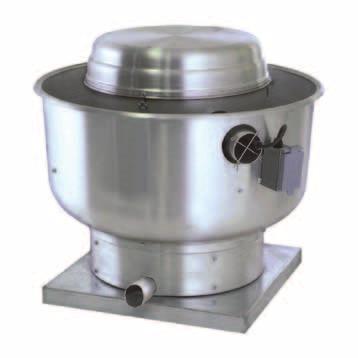
21 L L 1 HR elt rive High Velocity Restaurant-uty Utility Set HR SRIS HIGH VLOITY RSTURNT UTY UTILITY ST HR SRIS HIGH VLOITY RSTURNT UTY UTILITY ST HR SRIS HIGH VLOITY RSTURNT UTY UTILITY ST HR SRIS HIGH VLOITY RSTURNT UTY UTILITY ST 60º 60º H H 60º Install Pin for Install Pin for Safety Lock Safety Lock over Removed over Removed 60º H H Install Pin for Safety Lock Install Pin for overlock Removed Safety over Removed FF GG Features & enefits Virtually grease-free rooftops F No added options needed F No pre-mature motor failures Handles high temperature, heavy grease applications urb mounted design Handles up to 9000 and 4.5 w.g. static pressure Pleasing aesthetics high quality enamel painted housing Ventilated motor housing for motor, shaft and drive protection Rigid motor plate assembly Non-overloading, welded steel backward inclined wheel is statically and dynamically balanced and permits usage on high static pressure applications alancing weights are mechanically fastened Heavy duty bearings in excess of 00,000 hours of operation Motor base and shaft seals provide a double layer of protection to eliminate water leaks into the building and grease build-up on motor Grease laden air does not enter the motor compartment, increasing the life of the motor and allowing use on high temperature and grease applications ischarge section continuously welded to avoid grease leakage ontinuously welded scroll to prevent grease leakage onto the rooftop Grease drain centered and fully welded onto discharge elbow onvenient access door, with gasket, for easy cleaning and maintenance to the wheel LIST Newly engineered hinged base for improved installation ertifications Models HR13 thru HR0 are UL Listed for the removal of smoke and grease laden vapors, UL and UL705 and are in conformance with NFP-96. J J 443/16 3/16 GG G R R G G=R+3" G=R+3" Remove Pin Pin Remove To Open To Open uctwork etween uctwork etween xhaust Riser On Hood Riser On Hood and xhaust Fan (by others) and Fan (by others) J J 4 3/16 G R 4 3/16 G R G=R+3" G=R+3" Measurements Models imension HR13 HR16 HR0 1 1/ 5 1/ 9 1/ 1 3/ / 17 1/ 1 1/ / 48 1/ 56 F 9 1/8 33 3/4 36 1/ G 7 1/ 31 1/ 35 7/8 H 1 1/ 30 3/8 9 1/ J 1 5/8 14 5/8 16 5/8 R Roof Opening 18 6 Wheel ia. 13 1/ 16 1/ 0 1/ Weight Remove Pin To Open Remove Pin To Open uctwork etween xhaust Riser On Hood uctwork and Fan etween (by others) xhaust Riser On Hood and Fan (by others)
22 HP (rake Horsepower): The actual power developed by a motor as measured by the force applied to a shaft or flywheel. Performance 0.00 sp 0.50 sp 1.00 sp 1.50 sp.00 sp.50 sp 3.00 sp 3.50 sp 4.00 sp 4.50 sp MOL HR / / / / / / / / / 1.9 HR / / / / / / / / 1.85 HR / / / / / / / 1.80 HR / / / / / / 1. HR / / / / / / / 1.65 HR / / / / / / / 1.79 HR / / / / / / / 1.94 HR / / / / / / 1.78 HR / / / / / / 1.96 HR / / / / / 1.81 HR / / / / 1.67 HR / / / / 1.88 HR / / / 1.74 HR / / / / / / / / / 3.99 HR / / / / / / / / / 4.47 HR / / / / / / / / 4.46 HR / / / / / / / 4.50 HR / / / / / / 4.55 HR / / / / / 4.58 HR / / / / 4.58 HR / / / 4.58 The data supplied are performance snapshots and do not include our entire range. Please consult factory representative for more information / / 4.56

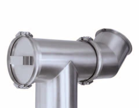
23 L L 3 I-RM elt rive Restaurant uty Utility Set RV.# 09/05/003 Shaft iameter U G T K W HH P Features & enefits Full M LSS I operation ontinuously welded housing UL Listed for restaurant duty grease drain will not clog leanout door with latches provide easy access without tools Upblast discharge directs air away from floor Vented motor cover for weather protection O H Options Heat Slinger Shaft Seal Vibration Isolators mergency isconnect Switch ertifications LIST Models IRM thru I4RM are UL Listed and are in compliance with UL Standards and NFP96. S V aptiveire certifies that Models IRM thru I7RM shown herein are licensed to bear the M seal. The ratings shown are based on tests and procedures performed in accordance with M Publication 11 and comply with the requirements of the M ertified Ratings Program. F Optional Support Rails FF Performance Models im U 3 5/8 30 1/ / / / / / / / / / / / / /8 15 3/4 17 5/8 19 3/8 1 1/4 3 5/ /8 31 3/4 34 7/8 38 5/8 8 1/4 9 7/8 3/ /8 14 1/ 15 3/4 17 5/8 19 3/8 1 1/4 3 5/ /4 F 7 3/4 33 1/4 34 1/8 35 3/8 36 1/ 37 7/8 46 7/ / / / / /4 G 15 1/4 0 1/16 0 1/16 0 1/ / / /16 H 1 5/16 9 1/8 9 1/8 9 1/ /8 40 7/8 46 1/ 46 1/ 64 3/4 64 3/4 64 3/4 K 13 3/ / / / / /16 5 1/4 5 1/4 9 15/ / /8 O / /8 15 7/8 17 3/8 19 3/8 1 1/4 3 5/ /8 31 3/ /4 P 17 1/ /8 1 1/8 1 1/8 1 1/8 7 11/ / / / S 11 3/4 11 1/ 11 1/ 11 1/ 11 1/ 11 1/ 14 5/8 14 5/8 18 9/ / T 11 7/ / / / / /16 3/4 3/4 5 1/ 5 1/ V n/a 13 1/ /4 16 3/8 17 3/4 19 3/4 1 5/8 3 3/8 3 3/8 8 9/ / /16 HH W FF Shaft ia. 3/ /16 1 3/16 1 3/16 1 3/16 1 7/16 1 7/ / / /16 Weight See performance data and charts on page 5, 6 & 7
24 4

25 L L 5 I- elt rive General uty Utility Set L Shaft iameter T G T K W HH P Features & enefits Standard top horizontal discharge ischarge position can be easily rotated in 45º increments in the field vailable in W or W rotation orrosion resistant enamel finish O H Options Heat Slinger Shaft Seal mergency isconnect Switch Vibration Isolators ack raft amper Inlet & Outlet Guards V S F ertifications aptiveire certifies that Models I thru I7 shown herein are licensed to bear the M seal. The ratings shown are based on tests and procedures performed in accordance with M Publication 11 and comply with the requirements of the M ertified Ratings Program. Optional Support Rails LIST Models I thru I7 are UL Listed and are in compliance with UL705 Standards. FF Performance Models im T 6 3/4 33 1/ / / /8 41 1/4 49 1/8 51 1/ 57 7/8 60 1/ 75 3/ / / / /8 15 3/4 17 5/8 19 3/8 1 1/4 3 5/ /8 31 3/4 34 7/ /4 9 7/8 3/ /8 14 1/ 15 3/4 17 5/8 19 3/8 1 1/4 3 5/ /4 F 7 3/4 33 1/4 34 1/8 35 3/8 36 1/ 37 7/8 46 7/ / / / / /4 G 15 1/4 0 1/16 0 1/16 0 1/ / / /16 H 1 5/16 9 1/8 9 1/8 9 1/ /8 40 7/8 46 1/ 46 1/ 64 3/4 64 3/4 64 3/4 K 13 3/ / / / / /16 5 1/4 5 1/4 9 15/ / /8 L 17 3/8 0 1/ 1/ 4 11/16 6 7/8 9 5/8 3 1/4 35 5/ /4 50 3/4 50 3/4 57 O / /8 15 7/8 17 3/8 19 3/8 1 1/4 3 5/ /8 31 3/ /4 P 17 1/ /8 1 1/8 1 1/8 1 1/8 7 11/ / / / S 11 3/4 11 1/ 11 1/ 11 1/ 11 1/ 11 1/ 14 5/8 14 5/8 18 9/ / T 11 7/ / / / / /16 3/4 3/4 5 1/ 5 1/ V n/a 13 1/ /4 16 3/8 17 3/4 19 3/4 1 5/8 3 3/8 3 3/8 8 9/ / /16 HH W FF Shaft ia. 3/ /16 1 3/16 1 3/16 1 3/16 1 7/16 1 7/ / / /16 Weight
26 6 HP (rake Horsepower): The actual power developed by a motor as measured by the force applied to a shaft or flywheel. Performance MOL Outlet Velocity FPM I / RM I / RM I / RM I / RM I / RM I1 / RM I1 / RM I1 / RM I1 / RM I1 / RM I1 / RM I1 / RM I1 / RM I1 / RM I1 / RM I13 / RM I13 / RM I13 / RM I13 / RM I13 / RM I13 / RM I13 / RM I15 / RM I15 / RM I15 / RM I15 / RM I15 / RM I15 / RM I15 / RM I15 / RM I15 / RM I16 / RM I16 / RM I16 / RM I16 / RM I16 / RM I16 / RM I16 / RM I16 / RM I16 / RM I16 / RM I16 / RM sp 0.50 sp 1.00 sp 1.50 sp.00 sp.50 sp 3.00 sp 3.50 sp 4.00 sp / / / / / / / / / / / / / / / / / / / / / / / / / / / / / / / / / / / / / / / / / / / / / / / / / / / / / / / / / / / / / / / / / / / / / / / / / / / / / / / / / / / / / / / / / / / / / / / / / / / / / / / / / / / / / / / / / / / / / / / / / / / / / / / / / / / / / / / / / / / / / / / / / / / / / / / / / / / / / / / / / / / / / / / / / / / / / / / / / / / / / / / / / / / / / / / / / / / / / / / / / / / / / / / / / / / / / / / / / / / / / / / / / / / / / / / / / / / / / / / / / / / / / / / / / / / / / / / / / / / / / / / / / / / / / / / / / / / / / / / / / / / / / / / / / / / / / / / / 6.89 Performance shown is for installation Type ; Free Inlet, Free Outlet. Power Rating (HP) does not include rive Losses. Performance Ratings do not include the effects of appurtenances in the air stream. The Sound Ratings shown are loudness values in fan sones at 5 ft. (1.5m) in a hemispherical free field calculated per M Standards 301. Values shown are for installation Type ; Free inlet fan sone levels. The M ertified Ratings Sound Seal applies to Sone Ratings only.
27 7 HP (rake Horsepower): The actual power developed by a motor as measured by the force applied to a shaft or flywheel. Performance 0.00 sp MOL Outlet Velocity FPM I18 / RM I18 / RM I18 / RM I18 / RM I18 / RM I18 / RM I18 / RM I18 / RM I18 / RM I18 / RM I18 / RM I18 / RM I18 / RM I18 / RM I0 / RM I0 / RM I0 / RM I0 / RM I0 / RM I0 / RM I0 / RM I0 / RM I0 / RM I0 / RM I0 / RM I0 / RM I0 / RM I0 / RM I / RM I / RM I / RM I / RM I / RM I / RM I / RM I / RM I / RM sp 1.00 sp 1.50 sp.00 sp.50 sp 3.00 sp 3.50 sp 4.00 sp / / / / / / / / / / / / / / / / / / / / / / / / / / / / / / / / / / / / / / / / / / / / / / / / / / / / / / / / / / / / / / / / / / / / / / / / / / / / / / / / / / / / / / / / / / / / / / / / / / / / / / / / / / / / / / / / / / / / / / / / / / / / / / / / / / / / / / / / / / / / / / / / / / / / / / / / / / / / / / / / / / / / / / / / / / / / / / / / / / / / / / / / / / / / / / / / / / / / / / / / / / / / / / / / / / / / / / / / / / / / / / / / / / / / / / / / / / / / / / / / / / / / / / / / / / 9.09
28 8 HP (rake Horsepower): The actual power developed by a motor as measured by the force applied to a shaft or flywheel. Performance 0.50 sp 1.00 sp 1.50 sp.00 sp.50 sp 3.00 sp 3.50 sp 4.00 sp Outlet Vel sp MOL FPM I4 / RM / / / 1.3 / /.41 9 / / / 4.4 I4 / RM / / 1. 3 / 1. 6 /.35 8 / / / / / / 1.14 / / / / / / / / / / / / / / / / / /.41 3 / / / / / / / / / / / / / / / / / / / / / / / /. 64 / / / / / / / / / / / / / / / / / 1.71 / / /.1 68 / / / / / / / / / / / / / / 1.80 /.41 7 / / / / / / / /.1 3 /.89 7 / / / / / / /.00 3 /.69 5 / / 4. 3 / / / / / /.5 7 / / / / / / / / / / / / / / / /.4 3 / / / / / / / / / / / / / / / / / / / / / / / /.0 55 / / / / / / / / / / / / / / / / / / / / / / / / / / / / / / / / / / / I4 / RM I4 / RM I4 / RM I4 / RM I4 / RM I4 / RM I4 / RM I4 / RM I4 / RM I4 / RM I7 / RM I7 / RM I7 / RM I7 / RM I7 / RM I7 / RM I7 / RM I7 / RM I7 / RM I7 / RM I7 / RM I7 / RM I7 / RM I7 / RM Performance shown on both pages is for installation Type ; Free Inlet, Free Outlet. Power Rating (HP) does not include rive Losses. Performance Ratings do not include the effects of appurtenances in the air stream. The Sound Ratings shown are loudness values in fan sones at 5 ft. (1.5m) in a hemispherical free field calculated per M Standards 301. Values shown are for installation Type ; Free inlet fan sone levels. The M ertified Ratings Sound Seal applies to Sone Ratings only.

29 9 -IRM elt rive General uty Utility Set Features & enefits Full M LSS 1 operation Vented motor cover for weather protection UL Listed for restaurant duty Upblast discharge directs air away from floor ontinuously welded housing leanout door with latches provide easy access without tools grease drain will not clog Shaft Seal mergency isconnect Switch Options Heat Slinger Vibration Isolator Grease up xtra elts Two Speed Wiring Package VV Package Manual ontrol VV Package Static Pressure ontrol VV Package Pre-Set Speeds ertifications Models 1IRM thru 4IRM are TL Listed under file numbers and and comply with UL705 (electrical) and UL Standards and S Std., No 113. Measurements MOL WHL G H I J K L N P Q 9 I 9 3/16 7 1/ 6 11/3 0 1/8 9 3/8 1 11/ /8 1 3/4 1/ 7 7/8 3 M 19 1/4 3/8 15 3/8 R SHFT I 5/8 8 3/16 8 3/16 3 3/16 1/4 1 9/ / /8 6 1/ 1 3/4 3/8 17 3/16 1 I 1 1/4 13 1/8 9 13/16 4 1/ /8 3 11/ /4 11 1/ /4 1 3/4 7/16 5/ I / /8 17 5/8 4 1/ / 15 7/ /8 6 1/4 9/16 7 5/ I 18 1/4 19 9/ /8 35 1/ 1 1/ 5 1/4 5/8 15 5/ / /8 16 7/8 31 7/8 9/ / /16 0 I 0 1 7/ / /8 3 1/ 5 3/3 5/8 3/ /16 1 3/ / / /8 9/ /8 5/8 1 3/16 I 1/4 3 13/ /16 4 7/8 5 7/8 6 1/16 6 1/8 1/4 16 1/ 3 1/ 43 15/16 0 1/ /16 9/ / /16 4 I 4 1/ 6 3/ /8 49 9/16 7 7/8 6 1/8 6 1/8 1/4 16 1/ 5 7/8 45 1/ / /16 9/ /16 6 1/8 1 3/16 7 I / /4 7 1/4 30 3/8 1/4 18 3/8 8 9/ /8 4 1/4 45 7/3 9/ / /16 30 I / /4 36 1/4 9 1/ / / / /4 9/ / /16 36 I 36 1/ 39 1/8 9 3/ /8 43 7/8 11 3/8 47 7/8 38 5/ / /8 9/ / /16 5/8 3/4
30 30 HP (rake Horsepower): The actual power developed by a motor as measured by the force applied to a shaft or flywheel. Performance Static Pressure in Inches W.G. MOL OV FPM IRM / / / / / / / / IRM / / / / / / / / 1.9 1IRM / / / / / / / / IRM / / / / / / / / 1.6 1IRM / / / / / / / / IRM / / 0.73 / / / / / /.01 1IRM / / / / / / / /.6 1IRM / / / / / / / /.53 1IRM / / / / / / / /.84 1IRM / / / / / / /.91 15IRM / / / / / / / / IRM / / / / / / / /.07 15IRM / / / / / / 1.75 /.07 4 /.40 15IRM / / / / / / / /.81 15IRM / / / / /.0 14 / /.9 43 / IRM / / / /.3 54 / / / IRM / /. 6 / / / IRM / / / / / / / /.06 18IRM / / / / / / / /.3 18IRM / / / / / / /. 170 /.61 18IRM / / / / / / / /.9 18IRM / / / / / / / / IRM / / / / / / / / IRM / / / / /.8 17 / / / IRM / / / / / / / 4. 18IRM / / / / / / IRM / / / / / IRM / / / IRM / / / / / / / / IRM / / / / / / / / IRM / / / / / / / / IRM / / / / / / / / IRM / / / / / / / / IRM / / / / / / / / IRM /.16 / / / / / / / IRM / / / / / / / / 8. 4IRM / / / / / / / /.0 4IRM / / / / / / IRM / / / / / IRM / / / 9.38 Speed () shown is nominal and performance is based on actual speed of test. Performance shown is for installation Type ; Free Inlet, Free Outlet. Performance rating includes effect of bird screen in the air stream.


31 31 USI Utility Set, Restaurant uty Features & enefits Full M LSS 1 operation Vented motor cover for weather protection UL Listed for restaurant duty Upblast discharge directs air away from floor Steel sides and scroll bands are lock formed asily accessible clean out door 1-1/ grease drain will not clog Fan is moisture resistant for high humidity applications Shaft Seal Options Heat Slinger. mergency isconnect Switch. Vibration Isolators. VV Package - Manual ontrol. VV Package - Static Pressure ontrol. VV Package - Pre-Set Speeds. ertifications Models USI0 thru USI365 have been certified by ITS. This certification mark indicates that the product has been tested to and has met the minimum requirements of a widely recognized (consensus) U.S. products safety standard, that the manufacturing site has been audited, and that the applicant has agreed to a program of periodic factory follow-up inspections to verify continued performance. aptiveire certifies that Models USI0 thru USI365 shown herein are licensed to bear the M seal. The ratings shown are based on tests and procedures performed in accordance with M Publication 11 and Publication 311, and comply with the requirements of the M ertified Rating Program. Models USI0 thru USI365 are TL Listed under report number 30959RT and comply with UL705 (electrical) and UL Standards and S Std., No 113. imensions Models (djustable) F G to 18.6 or 3.60 to I
32 3 HP (rake Horsepower): The actual power developed by a motor as measured by the force applied to a shaft or flywheel. Performance Static Pressure in Inches W.G. MOL OV FPM / / USI / / / / / / / 0.3 USI / / / / / / / 0.45 USI / / / / / 0.47 USI / 0.37 USI / / / / / / / / / / 1.13 USI / / / / / / / / / / 1.48 USI / / / / / / / / / / / / / 1.89 USI / / / / / 1.74 USI / / / / / / / / / / 1.31 USI / / / / / / / / / 1.5 USI / / / / / / / / / / / / / / / / / / / /.5 USI / / / / / / / / / / / / / / /.79 USI / / / / / / / 1.84 USI / / / / / / / /.0 03 /.1 0 / / /.79 3 / / /.71 4 /.91 USI / / / / / /.64 5 /.86 USI /. 191 / / /.80 USI / / / / / / / / 1.36 USI / / / / / / / 1.31 USI / / 0.58 / / / / / / / / / / / /.3 USI / / / / / / / / / / / /.80 USI / / / / / 1.71 USI / / / / / / / / / / / / /.84 USI / / / / / /.74 USI / / / /.61 USI / /.5 USI / / / / / / 1.67 USI / / / / / 1.80 USI / / / /.01 3 / /.11 7 /.44 7 /. 64 / / 3.00 USI / / /.3 / / / / / / / / / / 4.91 USI / / / / 3.3 USI / / / / / / / 4.56 USI / / / 1. USI / / / / / / / / / / / / / / 3.49 USI / / / / / / / / / / 4.56 USI / 1.7 USI / / / / / / / / / / / / 4.53 USI USI / / / / / / / / / / / / / / / / / / / / / / / / / 6.15 USI / / / / / /. 80 / / / / / / / 6.68 USI / / / / / / / / / / / / 7.6 USI / / / / / / / / / / / 7.33 USI / / / / / / / / / 6.94 USI / / / / / / / / 7.5 USI / / / / / / 6.96 USI / / / / 6.60 USI / 5.31 / 6.11 USI / 6.34 USI / / / / / / / / 3.97 USI / / / / / / / / / 5.50 USI / / / / / 3.67 / / / / 6.59 USI / / / / / / / / 7.05 USI / / / / / 6.3 USI / / 5.50 USI / / / / / / / / / / / 8.1 USI / / / / / / / / / / / 9.39 USI / / / / / / / / / 9.18 USI / / / / / / / 9.5 USI / / / / / 9.3 USI / / / / / / / / 9.13
 Motor cover Painted steel wheel Housing is cool rolled steel with enamel paint Options Filter section")
33 33 ISQ elt rive Inline xhaust Fan Features & enefits Two full size access doors provide easy access to the wheel, shaft, and bearings Wheels are backward inclined, non overloading Variable pitch motor allows for field adjustment and system balancing Thermal overload protection (single phase) Motor cover Painted steel wheel Housing is cool rolled steel with enamel paint Options Filter section Vibration isolators ertifications aptiveire certifies that Models ISQ- thru ISQ-7 are licensed to bear the M seal. The ratings shown are based on tests and procedures performed in accordance with M Publication 11 and 311 and comply with the requirements of the M ertified Ratings Program. Models ISQ- thru ISQ-7 are TL-listed and comply with UL705 (electrical) Standards and S., No. 113 Standards. Measurements MOL -1-1 lbs F ISQ- 16 1/ / /4 14 1/ /8 6 *LNGTH 0 1/16 0 9/16 19 Note: with the exception of ISQ- above, all models are cubed. ISQ-1 0 1/ / /4 13 1/4 14 1/ /8 6 ISQ-13 1/ /4 4 9/16 0 3/4 13 1/4 14 1/ /8 6 ISQ /16 0 7/ /4 14 1/ ISQ / /16 4 3/4 16 3/4 16 3/ /8 14 ISQ /16 5 3/8 31 3/16 7 1/8 16 3/4 16 3/ / 14 ISQ /16 7 3/4 33 7/8 9 7/8 16 3/4 16 3/ /8 14 ISQ- 34 1/ /16 3 3/4 1 3/4 1 3/ /8 0 ISQ / /4 1 3/ /8 0 ISQ /8 37 1/ 43 13/ /16 1 3/4 1 3/ /8 0
34 34 HP (rake Horsepower): The actual power developed by a motor as measured by the force applied to a shaft or flywheel. Performance 0.00 sp 0.5 sp 0.50 sp 0.75 sp 1.00 sp 1.5 sp 1.50 sp 1.75 sp.00 sp.5 sp.50 sp Model ISQ / / / / / / 0.35 ISQ / / / / / / / / / / 0.84 ISQ / / / / / / / / / 0.90 ISQ / / / / / / / / 0.98 ISQ / / / / / / 0.95 ISQ / / / / 0.98 ISQ / 0.86 ISQ / / / / / / / / / / / 1.16 ISQ / / / / / / / / / / / 1.9 ISQ / / / / / / / / / / / 1.43 ISQ / / / / / / / / / / 1.46 ISQ / / / / / / / / / 1.50 ISQ / / / / / / / 1.40 ISQ / / / / / / 1.46 ISQ / / / / / / / / 0.74 ISQ / / / / / / / / / / / 1.6 ISQ / / / / / / / / / / / 1.37 ISQ / / / / / / / / / / / 1.49 ISQ / / / / / / / / / / 1.45 ISQ / / / / / / / / / 1.43 ISQ / / / / / / / / 1.4 ISQ / / / / / / / 1.43 ISQ / / / / / / 1.44 ISQ / / / / / 1.46 ISQ / / / / 1.49 ISQ / / 1.3 ISQ / 1.36 ISQ / / / / / / / / 0.98 ISQ / / / / / / / / / / / 1.74 ISQ / / / / / / / / / / /.00 ISQ / / / / / / / / / 1.87 ISQ / / / / / / / 1.80 ISQ / / / / / / 1.97 Performance shown is for installation Type ; Free Inlet, Free Outlet. Power Rating (HP) does not include rive Losses. Performance Ratings do not include the effects of appurtenances in the air stream. The Sound Ratings shown are loudness values in fan sones at 5 ft. (1.5m) in a hemispherical free field calculated per M Standards 301. Values shown are for installation Type ; Free inlet fan sone levels. The M ertified Ratings Sound Seal applies to Sone Ratings only.
35 35 HP (rake Horsepower): The actual power developed by a motor as measured by the force applied to a shaft or flywheel. Performance 0.00 sp 0.5 sp 0.50 sp 0.75 sp 1.00 sp 1.5 sp 1.50 sp 1.75 sp.00 sp.5 sp.50 sp MOL ISQ / / / / 1.94 ISQ / / 1.93 ISQ / / / / 0.36 ISQ / / / / / / 0.80 ISQ / / / / / / / / / / 1.8 ISQ / / / / / / / / / / /.38 ISQ / / / / / / / / / / /. ISQ / / / / / / / / / /.97 ISQ / / / / / / / /.97 ISQ / / / / / /.98 ISQ / / /.66 ISQ / / / / / 0.83 ISQ / / / / / / / / 1.90 ISQ / / / / / / / / /.35 ISQ / / / / / / / / / /.77 ISQ / / / / / / / / / /.97 ISQ / / / / / / / /.8 ISQ / / / / / /.77 ISQ / / / /.61 ISQ / /.36 ISQ / / / / 0.59 ISQ / / / / / / 1.0 ISQ / / / / / / / / 1.96 ISQ / / / / / / / / / /.88 ISQ / / / / / / / / /.83 ISQ / / / / / / / /.85 ISQ / / / / / / /.91 ISQ / / / / / /.98 ISQ / 1.59V / / /.68 ISQ / / /.75 ISQ / /.8 Performance shown is for installation Type ; Free Inlet, Free Outlet. Power Rating (HP) does not include rive Losses. Performance Ratings do not include the effects of appurtenances in the air stream. The Sound Ratings shown are loudness values in fan sones at 5 ft. (1.5m) in a hemispherical free field calculated per M Standards 301. Values shown are for installation Type ; Free inlet fan sone levels. The M ertified Ratings Sound Seal applies to Sone Ratings only.
36 36 HP (rake Horsepower): The actual power developed by a motor as measured by the force applied to a shaft or flywheel. Performance 0.00 sp 0.5 sp 0.50 sp 0.75 sp 1.00 sp 1.5 sp 1.50 sp 1.75 sp.00 sp.5 sp.50 sp MOL ISQ / / / / / / / 1.65 ISQ / / / / / / / / / / 3.14 ISQ / / / / / / / / / / / 4.13 ISQ / / / / / / / / / / / 4.87 ISQ / / / / / / / / / 4.89 ISQ / / / / / / 4.54 ISQ / / / / 4.69 ISQ / 4.46 ISQ / / / / / / 1.56 ISQ / / / / / / / / / 3.13 ISQ / / / / / / / / / / / 4.60 ISQ / / / / / / / / / / / 5. ISQ / / / / / / / / / / / 6.00 ISQ / / / / / / / / / / / 6.95 ISQ / / / / / / / / / / 7.48 ISQ / / / / / / / / 7.49 ISQ / / / / / 6.89 ISQ / / / 6.98 ISQ / 7.19 ISQ / / / / / 1.7 ISQ / / / / / / /.37 ISQ / / / / / / / / / / / 4.83 ISQ / / / / / / / / / / / 5.4 ISQ / / / / / / / / / / / 6.01 ISQ / / / / / / / / / / / 6.70 ISQ / / / / / / / / / / 6.88 ISQ / / / / / / / / / 7.16 ISQ / / / / / / / 6.83 ISQ / / / / / / 7.1 ISQ / / / / 6.9 ISQ / / / 7.41 ISQ / 7.7 Performance shown is for installation Type ; Free Inlet, Free Outlet. Power Rating (HP) does not include rive Losses. Performance Ratings do not include the effects of appurtenances in the air stream. The Sound Ratings shown are loudness values in fan sones at 5 ft. (1.5m) in a hemispherical free field calculated per M Standards 301. Values shown are for installation Type ; Free inlet fan sone levels. The M ertified Ratings Sound Seal applies to Sone Ratings only.
 Thermal overload protection (single phase) Painted steel wheel Housing is cold rolled steel with enamel Options Filter section")
 U.S.")

37 37 ISQ irect rive Inline Inline xhaust Fan Features & enefits Two full size access doors provide easy access to the wheel, and motor Wheels are backward inclined, non overloading Speed ontrol allows for field adjustment and system balancing (Not installed on Size 15) Thermal overload protection (single phase) Painted steel wheel Housing is cold rolled steel with enamel Options Filter section Vibration isolators ertifications Models ISQ thru ISQ15 have been certified by ITS. This certification mark indicates that the product has been tested to and has met the minimum requirements of a widely reconized (consensus) U.S. products safety standard, that thr manufacturing site has been audited, and that the applicant has agreed to a program of periodic factory follow-up inspections to verify continued performance. aptiveire certifies that Models ISQ thru ISQ15 are licensed to bear the M seal. The rating shown are based on test and procedures performed in accordance with M ertified Rating Program. Models ISQ thru ISQ15 are TL listed under report number 30959RT and comply with UL705 and S., No.113 Standards (lectrical) standards. Measurements MOL -1-1 lbs F ISQ 16 1/ / / / /8 6 *LNGTH 0 1/16 0 9/16 19 Note: with the exception of ISQ above, all models are cubed. ISQ1 0 1/ / /4 1 13/ / /8 6 ISQ13 1/ /4 4 9/16 0 3/4 1 13/ / /8 6 ISQ15 4 9/16 0 7/ / /
38 38 HP (rake Horsepower): The actual power developed by a motor as measured by the force applied to a shaft or flywheel. Performance MOL Tip Speed ISQ ISQ ISQ ISQ ISQ sp 0.5 sp 0.50 sp 0.75 sp 1.00 sp 1.5 sp 1.50 sp 1.75 sp.00 sp Motor HP / / / / / / / / / / / / / / / / / / / / / / / / / / / / / / / / / / / / / / / / / / / / / / / / / / / / / / / / / / / / / / ISQ ISQ ISQ1 ISQ1 ISQ ISQ ISQ ISQ13 ISQ13 ISQ13 ISQ

39 L L 39 F- eiling and Inline entrifugal eiling Fan F400 to F1500 F0 to F300 F0 to F300 F400 to F1500 F Metal Grille w/ namel Finish Polimeric Grille Features & enefits xtremely quiet operation coustically insulated housing Integral back draft damper asily removable blower damper Resilient anti-vibration mounts isolate motor for smooth operation Thermally protected fan motor 10v, 40v, and 77v available Integral plug type disconnect an be ceiling or wall mounted G ischarge (diameter) Options Variable speed control Time delay switch Inline kit UL rated radiation damper Square to round discharge transition (see models 400 and larger) Metal grille (standard on size 400 and larger) rick vents Roof and wall caps ertifications LIST aptiveire certifies that Models F0 thru F1500 shown herein are licensed to bear the M seal. The ratings shown are based on tests & procedures preformed in accordance with M Publication 11 and Publication 311, and comply with the requirements of the M ertified Ratings Program. UL Listed for use over bathtubs and showers when connected to a GFI protected branch circuit. Measurements - ischarge (dia.) 6 Weight (lbs) / / 4 1/ /4 3 1/ / 4 1/ /4 11 3/4 3 1/ / 4 1/ /8 19 7/ /8 19 7/ MOL F G F0 1 1/4 1 1/4 11 3/ F /4 1 1/4 11 3/ F00 1 1/4 1 1/4 11 3/ F50 1 1/4 1 1/4 11 3/ F /4 1 1/4 11 3/4 14 F / 1 1/4 11 3/4 F / 1 1/4 F / F900 F1500
40 40 HP (rake Horsepower): The actual power developed by a motor as measured by the force applied to a shaft or flywheel. Performance /SONS Static Pressure (Ps inches of H0) MOL Nominal Voltage Max Hz Watts Hor Vert 0.0 Ps 0. Ps 0.15 Ps 0.50 Ps Ps 0.50 Ps 0.65 Ps Ps F0 10 V Hor SONS Hor Vert SONS Vert Hor SONS Hor Vert SONS Vert Hor SONS Hor Vert SONS Vert Hor SONS Hor Vert SONS Vert Hor SONS Hor Vert SONS Vert Hor SONS Hor Vert SONS Vert Hor SONS Hor Vert SONS Vert Hor SONS Hor Vert SONS Vert Hor SONS Hor Vert SONS Vert Hor SONS Hor Vert SONS Vert F150 F00 F50 F300 F400 F500 F700 F900 F V 10 V 10 V 10 V 10 V 10 V 10 V 10 V 10 V Ps Performance shown is for installation Type ; Free Inlet, Free Outlet. Power Rating (HP) does not include rive Losses. Performance Ratings do not include the effects of appurtenances in the air stream. The Sound Ratings shown are loudness values in fan sones at 5 ft. (1.5m) in a hemispherical free field calculated per M Standards 301. Values shown are for installation Type ; Free inlet fan sone levels. The M ertified Ratings Sound Seal applies to Sone Ratings only.

41 L L Series Inline uct lower eiling & abinet Fans Inline uct lower Inline uct lower G L J F M H K The aptiveire 00 Series inline duct blowers are ideal for applications requiring quiet, low break horse power fans for both make-up air and general exhaust. The low profile design allows for installation between 4 ceiling rafters. Optional Filters Optional Filter N Features & enefits eiling or Inline fan UL705 compliant M Sound & ir ertified Thermal overload protection (single phase) 1" S P Options Vibration isolation Insulated housing isconnect switch filter R P 1" N " ertifications LIST aptiveire certifies that Models 07 thru are licensed to bear the M seal. The ratings shown are based on tests & procedures preformed in accordance with M Publication 11 and publication 311, and comply with the requirements of the M ertified Ratings Program. Models 07 thru are UL Listed and are in compliance with UL705 (lectrical) Standards. Measurements MOL F G H J 7 lower /4 1 3/4 14 1/ 9 5/8 1 1/4 1 1/4 9 lower 1/ /4 1 3/8 14 1/8 17 1/ 11 3/4 1 1/4 1 3/4 lower 30 1/8 4 3/ / 16 5/8 18 3/4 13 3/8 1 1/4 1 3/4 MOL K L M N P R S 7 lower 7/8 15 7/8 13 3/8 1 1/8 13 1/ 17 3/4 15 3/8 Shipping (lbs) 5 9 lower 7/ / / lower 7/8 0 1/ /8 1/
42 4 HP (rake Horsepower): The actual power developed by a motor as measured by the force applied to a shaft or flywheel. Performance Static Pressure in Inches W.G. MOL / / / / / / / / / / / / / / / / / / / / / / / / / / / / / / / / / / / / / / / / / / / / / / / / / / / / / / / / / / / / / / / / / / / / / / / / / / / / / / / / / / / / / / / / / / / / / / / / / / / / / / / / / / / / / / / / / / / / / / / / / / / / / / / / / / / / / / / / / 0.80 / / / / / / / / / / / / / / / / / / / / / elt drive losses are not included. Performance shown is for installation Type ; Free Inlet, Free Outlet. Speed () shown is nominal. Performance is based on actual speed of test. The Sound Ratings shown are for loudness values in fan sones at 5 0 (1.5m) in a hemispherical free field calculated per M Standards 301. Values shown are for installation Type ; Free inlet fan sone levels. Performance ratings include the effects of backguard in the airstream. For models shown on this page, the M ertified Ratings Seal applies to air and sound.
43 L L 43 PRSM Integral Shutter-irect rive xial Wall Mount xhaust Fans 0.8 x.50 Slot (8) F Features & enefits OSH rear guard standard Totally enclosed 115 volt motor uilt in shutter LIST ompletely assembled for easy installation J W ertifications Models PRSM7 thru PRSM4 are UL Listed and are in compliance with UL 705 (lectrical) Standards. G H Measurements 8 Wall Opening 8 1/ Weight (lbs) 9 1/ / / / / MOL F G H J PRSM7 11 1/ /16 9/16 3 9/ /8 PRSM 13 1/ /16 9/16 3 9/ /8 PRSM1 15 1/ /16 9/16 3 9/ /8 PRSM / /16 9/16 3 9/ PRSM18 1 1/ /16 9/16 3 9/16 14 PRSM4 7 1/ /16 9/16 3 9/16 0
44 44 HP (rake Horsepower): The actual power developed by a motor as measured by the force applied to a shaft or flywheel. Performance 0.00 sp 0.05 sp sp sp 0.0 sp 0.15 sp sp sp 0.00 sp 0.5 sp 0.50 sp Motor HP MOL Tip Speed PRSM / PRSM / PRSM / PRSM / PRSM / PRSM /

45 45 R-F ownblast irect rive Propeller Roof Mount xhaust Fans : +7 % 5 & $LU )ORZ Propeller irect rive Fans are the perfect low cost exhaust choice in the areas that have little or no ductwork, and thus, relatively low to moderate resistance. %FNGUIW 'PSHU 5 URRI RSHQLQJ Features & enefits Spun aluminum housing for rust-free weather resistant durability Propellers constructed with die formed blades riveted to a steel hub an be roof or wall mounted Standard bird screen Wire conduit to provide a clear channel for electrical connections mergency disconnect switch ' ' &XU ( *XJH 6WHHO &RQVWUXFWLRQ Options )OQJH Gravity damper Motorized damper Wall mount sleeve Roof curb ertifications aptiveire certifies that Models RTH thru R18TH are licensed to bear the M seal. The ratings shown are based on tests & procedures preformed in accordance with M Publication and comply with the requirements of the M ertified Ratings Program. Models R-F are TL Listed and are in compliance with UL705 (lectrical) Standards and S Std.., No Measurements MOL HT W RO Shipping (lbs) amper (sq) RF 9 1/4 18 5/ / R1F 9 3/4 0 5/ / R14F 1 5/8 7 5/ / R18F 14 3/8 33 9/ / Motor vailability MOL RF R1F R14F R18F 115v T
46 46 HP (rake Horsepower): The actual power developed by a motor as measured by the force applied to a shaft or flywheel. Performance Static Pressure in Inches W.G. MOL Tip Speed Motor HP RF / R1F / R14F / R18F / Speed () shown is nominal and performance is based on actual speed of test. Performance shown is for installation Type ; Free Inlet, Free Outlet. Performance rating includes effect of bird screen in the air stream


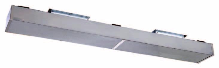
47 47 ccessories For Power Ventilators & urbs Shutters & ampers ampers vailable as gravity dampers, motorized dampers and wall shutters Gravity and motorized dampers are all aluminum construction Wall shutters are painted steel frames with aluminum shutter blades These all-aluminum, self-acting ack raft ampers open only when fans are in operation, and automatically close when fans are turned off. luminum, multi-leaf, interconnected blades with stainless steel sleeve bearings are set into square frames designed to be mounted inside of curb or framed in opening between the exhaust fan and the ductwork. For use in conjunction with Make-Up ir Units, Motorized ampers are used for positive control of the air-intake opening, to control backdraft, and to keep out wind, rain and snow. (Please note, dampers are not designed for use with up-blast units that exhaust grease-laden vapors). SSORIS FOR POWR VNTILTORS & URS urb daptors esigned to ease the installation of new fans onto existing roof curbs where the base of the fan differs from the existing roof curb onstructed of durable, maintenance-free aluminum Sizes to fit the most popular combinations. For unique applications, consult a aptiveire Representative Hinge Kits Provides easy access to fan wheel and ductwork for cleaning and service Square Roof urbs Grease ollection ox Made from 0 gauge, aluminized steel ontinuously welded construction vailable in 8, 1 or 18 high Pitched curbs available Single point grease collection system Protects roof surface Vented Roof urbs esigned to meet the NFP96 requirement for a 40 discharge height with our upblast restaurant exhaust fans. Supply Fan Unit xtension Provides a ft separation between the xhaust and Supply for compliance with NFP-96.
48 48 MU-F Roof or Wall Mount xial Radial Make-Up ir Fan : +7 % 5 & ' ' &XU ( *XJH 6WHHO &RQVWUXFWLRQ Used when fresh air is needed to replace exhaust air, commercial kitchens, office buildings, bakeries, laundries, factories, warehouses, foundries, locker rooms, etc. )OQJH Features & enefits Spun aluminum housing for rust free weather resistant durability Propellers constructed with die formed blades riveted to a steel hub an be roof or wall mounted Standard bird screen Wire conduit to provide a clear channel for electrical connections mergency disconnect switch Options Motorized damper Wall mount sleeve Roof curb ertifications Models MU14F thru MU18F are TL Listed and are in compliance with UL 705 (lectrical) Standards and S Std.., No Measurements MOL HT W RO MU14F 1 5/8 7 5/ / 1 16 Shipping (lbs) 45 amper (sq) 15 MU18F 14 3/8 33 9/ / Measurements Static Pressure in Inches W.G. MOL Tip Speed Motor HP MU14F / MU18F /

49 49 MU-F conomy Make-Up ir Gravity Hood and Relief W HT urb 0 Gauge Steel onstruction 3" Flange The aptiveire MU-F is a non-motorized gravity vent. It is an economical choice when fresh air intake or pressure relief are needed. Features & enefits UR IMNSIONL T MUF NON-MOTORIZ GRVITY UNITS IMNSIONL T FN MOL HT W MU1F / MU314F / MU418F Roof mounted fans Standard bird screen ackdraft amper Installation ackdraft amper RO WIGHT L FN MOL 15 1/ 18 MU1F 17 1/ / MU314F 19 1/ 1 6 1/ 3 MU418F 4 1/ / Options Motorized backdraft damper Hinged fan Pitched curb Insulated curb RO (roof opening) ir Flow or Measurements MOL HT W RO Weight (lbs) amper (sq) MU1F / 15 1/ 17 1/ MU14F / 19 1/ 1 15 MU18F / 4 1/ Static Pressure in Inches W.G. * gainst Static Resistance MU1F 00 * pproximate against static MU14F 1475 Resistance is based on throat area MU18F 400 Velocity of approximately 100 FPM MOL


50 Modular Make-Up ir Systems Standard Features G90 Galvanized onstruction asy ccess oors Rigid ommon ase Pre-wired, Pre-piped ontrols vailable Modules ir Handler irect Fired Heat Indirect Fired Heat lectric Heater vaporative ooler Heating and ooling oils Filtration asic Units Series ir Handler - Series irect Fired -I Series Indirect Fired - Series lectric Heater lower performance up to,000 Vibration isolation Horizontal or down discharge High efficiency motors djustable drive sheaves Removable doors for easy access Optional intake damper TL Listed 19,000 to,500,000 TUs 1,000 to 1,000 Service doors on both sides Improved profile plate configuration Stainless steel burner 30 to 1 turn down modulation lectronic flame modulation irflow switch Natural gas applications conomizer inlet thermostat Redundant gas valves 10 volt control transformer with single point electrical connection Intermittent spark pilot with timed safety lockout High temperature limit switch TL Listed 00,000 to 800,000 TU input 1,300 to 13,000 Stainless steel burner, heat exchanger, and drip pan lectronic flame modulation Natural gas applications Power vent with proving switch Redundant gas valves Service doors on both sides for burner maintenance 10 volt control transformer with single point electrical connection Intermittent spark pilot with timed safety lockout High temperature limit switch TL Listed ir Flow Switch Rated up to 35KW and 400,000 ontrols for stand alone or integrated operation Redundant safety controls lectric coil safety equipment Temperature control system ontactor and overload Observation port access doors to electrical controls and blower/ motor assembly Motorized back draft damper Optional Motorized amper Gravity amper Optional LP gas application Freeze protection High / Low gas pressure switches Room temperature controls Remote Panel Motorized amper Optional LP gas application Freeze protection Room temperature controls High / Low gas pressure switches Remote Panel Motorized amper Optional Freeze protection Room temperature controls Remote Panel Motorized amper Modules oils Mixing ox V-ank vaporative ooler s X 3-50 ton cooling 00-14,00 1 or circuit coils Stainless steel drain pan oil access doors Insulated casing Hot Water Up to 1,186,90 TU/Hr 15,700 Max oil ccess oors Insulated casing Steam Up to 1,3,830 TU/Hr 15,700 Max Rated for 5 psi supply oil ccess oors Insulated casing lectric -35KW Staged heating control irflow switch lower interlock relay 400,000 oil access doors Insulated casing Power transformer Up to,000 Return and fresh air damper common linkage Single damper actuator screen keeps debris out of airstream Used where fan faces high velocity air uilding static pressure control lectric -position control Manual potentiometer control Screen Used on V-bank or evaporative coolers Up to,000 industrial metal mesh filters Fully insulated Industrial metal mesh filters Large filtration area low air velocity ownturn Plenum urb mountable Sloped screen Rain gutters Poly Media or 1 thick Kuul media Media is Removable Up to,000 No moving parts Utilizes standard line water pressure ccess door for media and controls uilt-in water, filter, moisture control, and temperature switch No standing water reduces bacteria growth Optional Freeze protection fill and drain kit
51 51 NSU Standard Rooftop Filtered Untempered Make-Up ir F F Filter FILTR This economical blower is designed to deliver fresh outside make-up air for installations requiring frequent air changes. Units are designed for outdoor applications, and are available in down or horizontal discharge configurations. H 3" ontinuous Flashing G G Units are available in sizes up to 6,000, and external static pressure up to W.G. Units have a removable lid to provide ample access to all internal components. Standard features include vibration isolation, high efficiency motors, and adjustable drive sheaves. Units consist of a galvanized enclosure with a blower, motor, pulleys and belt(s). This unit has a standard horizontal inlet designed to accommodate an outside air inlet hood with standard filters. Features & enefits isconnect switch Spring loaded lid latches G90 galvanized steel housing lower mounted on vibration isolators High efficiency motors Variable pitch motor pulley allows for field adjustments and system balancing own or straight through discharge washable filters Options Gravity intake damper Motorized intake damper Roof curbs Wall mount kit VV packages ertifications TL Listed and ertified to UL705 (electrical) Standards Measurements MOL F G H Filter Size Weight NSU1-G () 16 x0 175 NSU-G / / 14 () 0 x5 75 NSU-G / / 14 (3) 0 x5 315
52 5 HP (rake Horsepower): The actual power developed by a motor as measured by the force applied to a shaft or flywheel. Performance Static Pressure in Inches W.G. MOL NSU1-G / / / / / / / / / 1.1 NSU1-G / / / / / / / / / 1.37 NSU1-G / / / / / / / / / 1.7 NSU-G / / / / 0.44 NSU-G / / / / / / 0.90 NSU-G / / / / / / / / / 1.70 NSU-G / / / / / / / / 1.93 NSU-G / / / / / / 1.97 NSU-G / / / 1.94 NSU-G / / / 0.57 NSU-G / / / / 0.95 NSU-G / / / / / 1.44 NSU-G / / / / / /.03 NSU-G / / / / /.6 89 / / / 3.00 NSU-G / / / / / / / / / 3.86 NSU-G /.0 63 / / / / / / / / 4.56

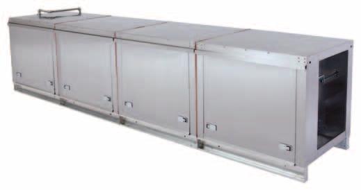
53 53 Series Modular Rooftop Untempered Make-Up ir The ir Handler Unit is the heart of the modular fan system. It is designed to deliver fresh outside make-up air for installations requiring frequent air changes. Units are designed for indoor or outdoor applications, and are available in down or horizontal configurations. Packages are available in sizes up to,000 and external static pressures up to W.G. Units have large doors on both sides to provide ample access to all internal components. Standard features include vibration isolation, high efficiency motors and adjustable drive sheaves. Units consist of a galvanized enclosure with a blower, motor, pulleys and belt(s). The blower module has a standard horizontal inlet designed to accommodate an outside air inlet hood with a standard filters and screen. Features & enefits isconnect switch Vibration isolation Lifting points High efficiency motors ompact weatherproof design djustable drive sheaves Horizontal or down discharge washable filters Inlet screen G90 galvanized steel asy accessibility to all components for inspections, maintenance and cleaning Options Gravity intake damper Motorized intake damper Roof curb Wall mount kit Mixing box with damper control X cooling coils Hot water/steam coils Indoor hanging cradle Insulated housing vaporative cooling intake VV packages ertifications The Series Models have been certified by ITS. This certification mark indicates that the product has been tested to and has met the minimum requirements of a widely recognized (consensus) U.S. products safety standard, that the manufacturing site had been audited, and that the applicant has agreed to a program of periodic factory follow-up inspections to verify continued performance. TL Listed and ertified to UL705 (electrical) Standards. Measurements MOL Weight 48 3/8 7 3/8 7/ /8 37 3/ / /8 37 3/ / /8 41 3/8 96 3/ /8 48 7/ / / / /16 5 3/4 550
54 54 HP (rake Horsepower): The actual power developed by a motor as measured by the force applied to a shaft or flywheel. Performance Static Pressure in Inches W.G. MOL / / / / / / / / / / / / / / / / / / / / / / / / / / / / / / / / / / / / / / / / / / / / / / / / / / / / / / / / / / / / / / / / / / / / / / / / / / / / / / / / / / / / / / / / /.30 7 / / / / / / /. 07 / / / / / / / / / / / /.6 89 / / / / / / / / / / / / / / / / / / / / / / / / / /.6 89 / / / / / / / / / / / / /.0 63 / / / / / / / / / / / / / / / / / / / / / /.57 4 / / / / / / / / / / / / / / / / / / / / / / / / / / / / / / / / / / / / / / / / / / / / / / / / / / / / / / / / / / / / / / / / / / / / / / / / / / / / / / / / / / / / / / / / / / / / 1. 3 / / / / / / / / / /.4 39 / / / / / / / / / / / / / / / / / / / / / / / / / / / / / / / / / / / / / / / / / / / / / / / / / / / / / / / / / / / / / / / / / / / / / / / / / / / / / / / / / / / / / / / / / / 16.3
55 55 Inline Series Filtered Untempered Make-Up ir INLIN SUPPLY FN INLIN SUPPLY FN RV.#1 RV.#1 Lifting Lug 4 Places Lifting Lug 4 Places 1 1 irflow Flex onduit For Field Wiring irflow Flex onduit For Field Wiring F F Uni-Strut ase For Hanging Places Uni-Strut ase For Hanging Places G H G H L The ir Handler Unit is the heart of the modular fan system. It is designed to deliver fresh outside make-up air for installations requiring frequent air changes. Units are designed for indoor applications, and are available in side discharge only. Packages are available in sizes up to 7,000, and external static pressures up to W.G. Units have large doors on both sides to provide ample access to all internal components. Standard features include vibration isolation, high efficiency motors, and adjustable drive sheaves. Units consist of a galvanized enclosure with a blower, motor, pulleys and belt(s). The blower module UNIT INFORMTION has a standard horizontal inlet with filters in fan inlet. MOL FILTR SIZ LOWR SIZ Features & enefits INLIN1-L (1) 16IN x 0IN IN INLIN1 (1) 16IN x 0IN IN INLIN (1) 0IN x 5IN 1 IN UNIT INFORMTION INLIN (1) 0IN x 5IN 15 IN MOL FILTR SIZ LOWR SIZ INLIN3 () 0IN x 5IN 18 IN INLIN1-L (1) 16IN x 0IN IN NOTS: INLIN1 (1) 16IN x 0IN IN 1) INLIN LL IMNSIONS R NOMINL N GIVN IN INHS. (1) 0IN x 5IN 1 IN ) INLIN SS OORS(1)LOT ON OTH SIS15OF 0IN x 5IN IN UNIT. () 0IN x 5IN 18 IN 3) INLIN3 INSULT ONSTRUTION. lower / Motor ccess oor / lower Motor ccess oor 1/4" 1/4" L WIGHT (lbs) WIGHT (lbs) Insulated housing Hanging cradle isconnect switch Lifting points NOTS: 1) LL IMNSIONS R NOMINL N GIVN IN INHS. Vibration isolation ) SS OORS LOT ON OTH SIS OF UNIT. 3) INSULT ONSTRUTION. High efficiency motors ompact weatherproof design djustable drive sheaves washable filters G90 galvanized steel asy accessibility to all components for inspection, maintenance & cleaning ccess doors located on both sides of unit Insulated construction 3 1/8 3 1/8 40 1/8 40 1/8 45 1/8 3 1/8 3 1/8 40 1/8 40 1/8 45 1/8 7 3/8 7 3/8 37 3/8 37 3/8 41 3/8 7 3/8 7 3/8 37 3/8 37 3/8 41 3/8 13 1/4 13 1/4 15 3/4 18 3/4 13 1/4 13 1/4 15 3/4 18 3/4 J Service isconnect Switch Service isconnect Switch Filter(s) J K Filter(s) K 1/4" Main Rails Not Included On 1-L Model 1/4" For Thru-Joist Main Rails Installation Not Included On 1-L Model For Thru-Joist Installation 11 1/ 11 1/ 13 7/ / 11 1/ 13 7/ N/ 11 13/ / /16 N/ 11 13/ / /16 P M P N M N F 8 1/8 8 1/8 9 3/8 5/16 F 1 5/8 8 1/8 8 1/8 9 3/8 5/16 1 5/8 UNIT IMNSIONS G H 1/16 N/ 9 3/4 6 1/ /4 33 1/16 UNIT IMNSIONS 36 3/4 33 1/16 G H 43 3/8 38 1/16 1/16 N/ 9 3/4 6 1/ /4 33 1/ /4 33 1/ /8 38 1/16 J /4 3/4 J /4 3/4 30 K K M 5 1/16 5 1/ / /16 M 5 1/16 5 1/16 5 1/ / /16 5 1/16 L N/ 3 11/ / /16 L 5 5/16 N/ 3 11/ / /16 5 5/16 N N Measurements MOL F G H J K Options INLIN1-GL* 3 1/8 7 3/8 13 1/4 11 1/ na 8 1/8 na 1/ VV packages INLIN1-G 3 1/8 7 3/8 13 1/4 11 1/ 11 13/16 8 1/8 9 3/4 6 1/ INLIN-G1 40 1/8 37 3/8 15 3/4 13 7/ /16 9 3/8 36 3/4 33 1/16 3/4 4 INLIN-G /8 37 3/8 18 3/ / /4 33 1/16 3/4 4 INLIN3-G /8 41 3/ /16 1 5/8 43 3/8 38 1/ ertifications The Inline models have been certified by ITS. This certification mark indicates that the product has been tested to and has met the minimum requirements of a widely recognized (consensus) U.S. products safety standards, that the manufacturing site has been audited, and that the applicant has agreed to a program of periodic factory follow-up inspections to verify continued performance. TL Listed and ertified to UL705 (electrical) Standards. MOL L M N P Filter Size lower Size Weight (lbs) INLIN1-GL* na 5 1/ /8 (1) 16 x0 140 INLIN1-G 3 11/16 5 1/ /16 (1) 16 x0 150 INLIN-G1 3 11/ / /16 (1) 0 x INLIN-G / / /16 (1) 0 x INLIN3-G18 5 5/16 5 1/ /16 () 0 x * I nline 1-GL: This model to be used for ceiling applications. The low profile model allows for installation between 4 ceiling rafters. P 1/8 5 13/ / /16 P 7 7/16 1/8 5 13/ / /16 7 7/16
56 56 HP (rake Horsepower): The actual power developed by a motor as measured by the force applied to a shaft or flywheel. Performance Static Pressure in Inches W.G. MOL INLIN1-G / / / / 0.30 INLIN1-G / / / 0.5 INLIN1-G / / / 0.33 INLIN1-G / / 0.3 INLIN1-G / 0.3 INLIN1-G 000 INLIN1-G / / / / / / / / / / / / / / / / 0.71 INLIN1-G / 0.77 INLIN-G1 000 INLIN-G1 50 INLIN-G / / / / / / / / / / / / / / / / / / / / / / / / / / / / / / / / / / / / / / / / / / / / / / / / / / 1.15 INLIN-G / / / / / / / / / 1.66 INLIN-G / / / / / / / / / 1.87 INLIN-G / / / / / / / / /. INLIN-G / / / / / / / / /.36 INLIN-G / / / / 1.63 / / /.4 10 / /.66 INLIN-G / / / / / /.3 11 / / /.98 INLIN-G / / / / / 0.94 INLIN-G / / / / / / 1.8 INLIN-G / / / / / / / 1.68 INLIN-G / / / / / / / /.1 44 /.41 INLIN-G / / / / / / / / /.61 INLIN-G / / / / / / / / /.85 INLIN-G / / / / / / / / / 3.1 INLIN3-G / / / / / / / / / 3.6 INLIN3-G / / / /. 77 / / / / / 4.51 INLIN3-G / / / / / / / 4.49
57 57 Series Modular Roof Mount and Inline irect Fired Heated Make-Up ir 4 5 Top View Y Top View W Y W Y W 4 5 X H Y Top View Top View W X Z Z X X H Side View Z The Series irect Gas-Fired Heater is TL listed for use in tempering make-up air. Unit meets NSI Z83.4a-001/S3.7a-001 safety standards and is designed for natural or propane gas applications. The heaters are rated for indoor/outdoor installations in commercial occupancies. unique feature is the self-adjusting burner profile plates allowing variable-air-volume applications. The plates ensure proper air velocity and pressure drop across the burner for clean combustion. Spring-loaded profile plates react to the momentum of the fresh air stream, therefore, no motors or actuators are needed to drive them, nor do they need to be manually set to a specific position. Side View Z Side View Side View F 0" High quipment urb F F G F 0" High quipment urb H square H square G 0" High quipment urb & Rail J 0" High quipment urb & Rail J Features & enefits G90 galvanized construction asy access doors Lifting points Redundant gas valves isconnect switch Pre-wired, pre-piped controls Horizontal or down discharge Vibration isolation Fully insulated casing w/ aluminum casting djustable drive sheaves Stainless steel burner lectronic flame modulation urner obsevation port 10 volt control transformer with single point electrical connection Intermittent spark pilot with timed safety lockout High temperature limit switch irflow proving switch conomizer inlet thermostat Motor starter Options Measurements Unit imensions MOL F /16 8 7/ / / 18 1/ 7 3/8 37 3/8 41 3/8 48 7/ /16 9 3/4 36 3/4 43 3/8 51 7/ / / / / / / / /16 7/ / /16 9 1/ 13 9/ /16 Propane fuel application Room override thermostat logged filter switch Motorized intake damper Remote control panel including summer/winter switch & operating lights Freeze stat with bypass timer Hi/Low gas pressure switches Room modulating thermostat onvenience outlet High gas pressure regulator ooling Interlock X cooling coils V-ank filter intake vaporative cooler intake uxiliary starters Sloped filter intake Indoor hanging cradle Inlet gas pressure gauge VV packages Roof curbs Measurements Unit Information ertifications MOL Filter Size urner Size Pipe Size Weight (lbs) 1- (3) 16 x 0 50 or 500 3/ (3) 0 x or (6) 16 x () 16 x / (8) 0 x / 1350 TL Listed and ertified to NSI Z83.4a-001/S 3.7a-001 lower MOL W X Y Z G H J /8 13 1/8 5 5/8 4 15/ n/a /8 18 5/8 8 3/8 6 15/ n/a /8 1 7/8 3/8 6 11/ n/a 4-4 7/8 4 7/8 11/16 8 9/ / /8 31 3/8 1 15/16 11/16-5 3/4 15 3/16 urb & Rail
58 58 HP (rake Horsepower): The actual power developed by a motor as measured by the force applied to a shaft or flywheel. Performance Static Pressure in Inches W.G. MOL / / / / / / / / / / / / / / / / / / / / / / / / / / / / / / / / / / / / / / / / / / / / / / / / / / / / / / / / / / / / / / / / / / / / / / / / / / / / / / / / / / / / / /.6 71 / / / / / / / / / / / / / / / / / / / / / / / / / / / / / / / / / / / / / / / / / / / / / / / / / / / / / / / / / / / / / / / / / / / / / / / / / /.4 80 / / / / / / / / / / / / / / / / / / / / / / / / / / / / / / / / /. 60 / / / / / / / / / / / / / / / / / / / / / / / / / / / / / / / / / / / / / / / / / / / / / / / / / / / / / / / / / / / / / / / / / / / / / / / / / / / / / / / / / / / / / / / / / / / / / / / / / / / / / / / / / / / / / / / / / / / / / / / / / / / / / / / / / / / / / / / / / / / / / / / / / / / / / / / / 18.0

59 59 - ompact irect Fired Heated Make-Up ir The irect Gas Fired Make-Up ir package is designed to deliver tempered make-up air for installations requiring frequent air changes. Units are designed for natural and propane gas applications, and for indoor and outdoor installation. irect Gas-Fired Heater, for use in tempering make-up air. The - is certified to the NSI Z83.4a-001/S 3.7a-001 combined safety standard. One size is available with a max TU rate of 41,90 and 1,800. unique feature is the self-adjusting burner profile plates allowing variable-air-volume applications. The plates ensure proper air velocity and pressure drop across the burner for clean combustion. Spring-loaded profile plates react to the momentum of the fresh air stream; therefore, no motors or actuators are needed to drive them, nor do they need to be manually set to a specific position. To satisfy a variety of installation requirements, packages are available in a number of configurations which include additions of filtered intake with easy access door and a trunk line that is used to move the air intake away from the grease laden exhaust air. Screened intakes are used to stop debris from being pulled into the heater; the screened intake attaches directly to the filtered intake or the trunk line. Features & enefits G90 galvanized construction asy access doors Pre-wired, pre-piped controls Horizontal and down discharge djustable drive sheaves Fully insulated casing Stainless steel burner with aluminum casting 10 volt control transformer with single point electrical connection Redundant gas valves lectronic flame modulation Intermittent spark pilot with timed safety lockout High temperature limit switch irflow proving switch conomizer inlet thermostat Motor starter isconnect switch urner observation port Options Propane fuel application Room override thermostat Remote control panel including summer/winter switch and operating lights Motorized intake damper Freeze stat with bypass timer Room modulating thermostat High gas pressure regulator onvenience outlet Screen intake uxiliary starters Inlet gas pressure gauge Indoor hanging cradle VV packages Roof curbs xtra set of V-belts ertifications Model is TL Listed under file number J and complies with NSI Z83.4a-001 Standards and S 3.7a-M99 Standards. TL Listed and ertified to NSI Z83.4a-001/S 3.7a-001
60 60 HP (rake Horsepower): The actual power developed by a motor as measured by the force applied to a shaft or flywheel. Performance Static Pressure in Inches W.G. MOL / / / / / / / / / / / / / / / / / / / / / / / / / / / / / / / / / / / / / / / / / / / 1. 7 / / / / / / / / / / / / / / / / / / / / / / / / / / / / / / / / 1.36 / / / / / / / / / / / / / / / / / / 1.98

61 61 -I Series Modular Rooftop Indirect Fired Heated Make-Up ir Y Indirect Module urb Outer Wall ischarge Opening H X Sloped Filter W F 0" High quipment Rail and urb G J Fresh, clean, tempered air. The Indirect Fired Gas Heated MakeUp ir unit is designed to deliver fresh, clean tempered air into any indoor environment. Units are designed for natural and propane gas applications, and for indoor or outdoor installation. ll units have the U.S. and anadian TL approval rating and are listed to the UL795 Standard. This product is available as a complete package that includes a blower module and the Indirect Fired Heater Module. The Indirect Fired Heater Module can also be purchased separately to integrate into an existing application. Packages are available in sizes up to 13,000 and 800,000 TUH gas input. Standard features include a spark ignited intermittent pilot with timed safety lockout, and a redundant combination valve. Units consist of a galvanized enclosure with a stainless steel burner and heat exchanger. uct furnace certified by the merican Gas ssociation and approved by the anadian Gas ssociation. The furnace module has a standard horizontal discharge duct connection and is located downstream of the blower module. This push-through design ensures that combustion fumes will never enter the fresh air stream in the event of a heat exchanger crack. down discharge configuration is available when combined with a downturn plenum. The blower module has a standard horizontal inlet designed to accommodate an outside air inlet hood with standard filters and screen. Measurements Unit imensions MOL F 1-I 4 9/ / /16 1 9/ /16 -I 118 9/ / /16 7 1/ 9 11/16 3-I 159 1/ / / 51 5/8 69 1/8 11 3/8 Measurements lower MOL W X Y Z G H 1-I 11 1/ 13 13/ / / -I 18 3/8 1 9/ / 3-I 18 3/8 1 1/ /16 Unit Information MOL Filter Size urner Size Pipe Size Weight (lbs) 1-I (3) 16 x / I (3) 0 x or I (6) 16 x or Features & enefits Options urner orifices for natural gas Stainless steel heat exchanger, burner, and drip pan 10 volt control transformer with single point electrical connection Redundant combination gas valve Intermittent spark pilot with timed safety lockout lectronic flame modulation High temperature limit switch Power vent with proving switch irflow proving switch Motor starter Lifting points ertifications urb & Rail J Propane fuel application Space heating control Motorized intake damper Remote control panel including summer/winter switch High gas pressure regulator onvenience outlet Mixing box with damper control X cooling coil vaporative cooler intake V-ank filter intake Sloped filter intake uxiliary starters Room override thermostat Freezestat with bypass timer High/Low gas pressure switch Inlet gas pressure gauge VV packages Indoor hanging cradle Roof curb logged filter switch ooling Interlock TL Listed and ertified to UL795. Model 3-1-I is also certified to G-3..
62 6 HP (rake Horsepower): The actual power developed by a motor as measured by the force applied to a shaft or flywheel. Performance Static Pressure in Inches W.G. MOL I-G / / / / / / / / / I-G / / / / / / / / / I-G / / / / / / / / / I-G / / / / / / / / / I-G 0 6 / / / / / / / / / I-G / / / / / / / / / I-G / / / / / / / / I-G / / / / / / / I-G / / / / / / I-G* / / / / / / / / I-G* / / / / / / / / I-G* / / / / / / / I-G* / / 1. 1 / / / / I-G* / / / / I-G* / / / 1.9 -I-G / / / / / / / / / I-G / / / / / / / / /.15 -I-G / / / / / / / /. 3 /.4 -I-G / / / / / / / /.35 3 /.69 -I-G / / / / / / / / /.99 -I-G / / / / / / / / / I-G / / / / / / / / / I-G / / / / / / / / / I-G / / / / / / / / / I-G15* / / / / / / / /.88 1 / 3.5 -I-G15* / / / / / / / / / I-G15* / / / / / / / / / 4.0 -I-G15* / / / / / / / / / I-G15* / / / / / / / I-G15* / / / / / I-G15* / / I-G / / / / / / / / /.68 3-I-G / / / / / / / / / I-G / / / / / / / / / I-G / / / / / / / / / I-G / / / / / / / / / I-G / / / /.59 / / / / / I-G / / / / / / / / / I-G / / / / / / / I-G / / / / / I-G18* / / / / / /.5 0 /.83 3-I-G18* / / / / / / / / / I-G18* / / / / / / / I-G18* / / / / / I-G18* / / / I-918* / / / / / /.5 0 /.83 3-I-918* / / / / / / / / / I-918* / / / / / / / / / I-918* / / / / / / / / / 6. 3-I-918* / / / / / / / / / I-918* / / / / / / / / / I-918* / / / / / / / I-918* / / / 9.6 *No ir affle: Internal furnace air baffle is removed at higher s to decrease internal furnace pressure loss / 1.81
63 63 Series Modular Roof Mount & Inline lectric Heated Make-Up ir Top View Top View Y The lectric Heater is used for tempering make-up air for installations requiring frequent air changes. The units are rated up to 35kW and,000 s, depending on heating requirements. The heaters are intended for indoor or outdoor installations in commercial kitchens, factories, foundries and similar commercial and industrial occupancies. Options Motorized intake damper Remote control panel Freeze stat with bypass timer Room temperature control onvenience outlet Mixing box with damper control X cooling coils vaporative ooler V-ank filter intake Sloped filter intake uxiliary starters Indoor hanging cradle VV packages Roof urbs ooling thermostat and interlock logged filter switch W Y X X H Z Z Side View Side View Features & enefits UL Listed insert the electric insert is a UL Listed sub-assembly Staged Heating ontrol 10 volt control transformer with single point electrical connection Galvanized, fully insulated casing ccess doors on both sides of unit Lifting points lower interlock irflow proving switch Temperature control system oil observation port High temperature limit Motor starter Vibration isolation High efficiency motors djustable drive sheaves Horizontal or down discharge isconnect switch W 0" High quipment urb 0" High quipment urb & Rail J H square G Measurements Unit imensions MOL 1--G 74 7/16 7 3/8 9 3/4 44 5/16 --G15 8 7/ /8 36 3/ /16 3--G / /8 43 3/8 51 5/ / 48 7/ / / 59 3/ /16 75 Measurements lower urb & Rail MOL W X Y Z G H J 1--G 11 3/8 13 1/8 5 5/8 4 15/ n/a --G /8 18 5/8 8 3/8 6 15/ n/a 3--G /8 1 7/8 3/8 6 11/ n/a /8 4 7/8 11/16 8 9/ / /8 31 3/8 1 15/16 11/16-5 3/4 15 3/16 Note: dditional configurations and options are available. Refer to website for specific details
64 64 HP (rake Horsepower): The actual power developed by a motor as measured by the force applied to a shaft or flywheel. Performance Static Pressure in Inches W.G. MOL / / / / / / / / / / / / / / / / / / / / / / / / / / / / / / / / / / / / / / / / / / / / / / / / /. 957 / / / / / / / / / / / / / / / / / / / / / / / / / / / / / / / / / / / / / / / / / / / / / / / / / / / / / / / / / / / / / / / / / / / / / / / / / / / / / / / / / / / / / / / / / / / / / / / / / / / / / / / / / / / / / / / / / / / / / / / / / / / / / / / / / / / / / / / / / 5. 4 / / / / / / / / / / / / / / / / / / / / / / / / / / / 4.7

65 65 H Horizontal Non-Recirculating Unit irect Fired Industrial Heated Make-Up ir 1. asing. urner Profile 3. urner 4. lower 5. urner Observation Port 6. ase & Lifting Lugs 7. Motor 8. Gas onnection 9. Main Fused isconnect. Manifold ontrols Vestibule 11. lectrical ontrols Vestibule Factory assembled, wired, and flame-tested FTURS & NFITS urner Observation Port SSORIS asy view of burner and pilot for start-up asing G-90 galvanized steel Interlocked wall seam and roof panels Weatherproof construction Standing roof seams (models 18 and larger) Single casing construction (models -30) Hinged service doors with flush-mount latches Six discharge options ouble wall doors ase and Lifting Lugs Formed G-90 galvanized-steel base irect floor or curb mount Standard heavy-duty lifting lugs Optional hanging-mount lifting lugs (models -30) Motor djustable profile plates Optional two-speed arrangement Optional Variable ir Volume arrangement Standard, high, open-drip proof with adjustable motor mounts V-belt drive Starter with burner interlock djustable drive up to and including 5HP urner Gas onnection Wide-range, high capacity line burner Up to 30:1 turndown ratio lectric-pilot spark ignition Manifold ontrols Vestibule urner Profile lower F-WI centrifugal blower assembly V-belt drive 0,000-hour greasable bearings (models 18-36) Permanently lubricated bearings (models -15) Solid steel shaft Split shaft with couplings on twin units ontrols lectric flame safety controls Ignition transformer irflow proving control High-temperature safety controls urner and blower service switches llows no water leakage into casing Weatherproof enclosure asy access to manifold and controls Manifold built to required codes (FM/IRI/FI) lectrical ontrols Vestibule Weatherproof enclosure asy access to manifold and controls xhaust-interlock terminals Terminal strip for quick service check lower and burner service switches Remote ontrol Panel Summer-Off-Winter switch lower On light urner On light Other lights available ischarge amper, TwoPosition Motor and Interlock Motor-operated parallel blade damper that prevents warm air from escaping the building through the unit. The motor-damper end switch energizes the starter circuit when the damper is in the full-open position, and returns to a closed position during shutdown. own discharge arrangement units available with our exclusive Hassle Free amper internally mounted in unit. ischarge ir iffuser ischarges air in four directions with vertical and horizontal blades, and is field-installed. The blades can be manually adjusted to set direction of airflow. Filter Section Removable, hinged access door, with a washable, aluminum-mesh filter, or a pleated filter. lso available with 1, 1.5 lb density insulation. Fresh-ir Hood with irdscreen Prevents rain or snow from entering the unit with a 1 mesh screen on hood face; sized to fit unit s fresh-air intake. Shipped loose to be field installed. Full-ownturn Inlet Hood Prevents rain and snow from entering the unit by bringing air in to the bottom of the hood with a 1 wire-mesh screen, and is field installed. Large hoods are shipped separately, and must be field assembled.
66 66 High fficiency Inlet Hood OPTIONS Pillow-lock earings, 0,000 hr separate section with high efficiency filters mounted on the unit s inlet side. vailable with 65%, 85%, or 95% cartridge filters and inlet-air hood. djustable rives Standard on 18 blowers and larger, and are rated at 0,000 to 00,000 hours. Inlet-Hood Filters, leanable, aluminum-mesh filters mounted on the inlet-hood face in lieu of a separate filter section. Not available on H-7 and larger models. Inlet Screen Prevents material from entering unit. 1 mesh screen fastens to unit s fresh-air intake. Inlet amper, Two-Position Motor and Interlock Motor-operated parallel blade damper that prevents outside air from entering the building through the unit. The motor damper end switch energizes the starter circuit when the damper is in the full-open position, and returns to a closed position during shutdown. Standard urb 4 roof curb formed of 1-gauge steel; 14 curb is also available. Shipped separately, and must be field assembled. Insulation, cant, and wood nailer by others. Fixed-pitched sheaves are standard on motors 30HP and larger. n adjustablepitch motor sheave is provided in lieu of the standard fixed-pitch sheave. asing Liners with Insulation Prevents insulation fibers from being drawn into air stream and discharged into conditioned space, and prevents physical abuse and moisture damage to insulation. Made of galvanized steel. xtended Grease Lines Lubrication lines from blower bearings to a common point on the unit s exterior. Units with permanently lubricated bearings to be changed to pillow block-type. Floor-Mounted Spring Isolators ox-type lifting points replace standard lifting eyes; 1 deflection spring mounts shipped loose for field installation. Hanging Spring Isolators, 1 Spring-Isolated lower and Motor Mounted on a 1 deflection spring isolated base. flexible duct connects the fan outlet to the unit s casing. Two-Speed amper Package Provides burner-profile damper that automatically maintains the correct burner velocity. lso dual airflow switches and rate-limiting control are included to prevent over-firing on low speed. VV amper Package Provides burner profile damper that automatically maintains the correct burner velocity with varying loads. lso dual airflow switches and rate-limiting controls are included to prevent over-firing. ONTROL OPTIONS Shipped loose for field installation. ischarge temperature control Space temperature control Painted asings RTIFITIONS One coat of beige air-dried enamel over a vinyl wash primer. aptiveire ertifies that Models H thru H36 shown herein are TL Listed to the NSI Z / S 3.7a-001 ombined Standards.
67 67 H Models -36 F Optional ischarge amper F Optional Hood Optional V-ank Filter Section H Optional ischarge ischarge Location lso amper vailable In ottom Or Top ischarge.00optional amper J ischarge Location.00 lso vailable In ottom Or Top ischarge.00 J H Optional amper Optional V-ank Filter Section Optional Hood G.00 Optional Filters In Face Of Hood G Optional Filters In Face Of Hood Ram Make-Up ir Unit Ram Make-Up ir Unit Measurements Unit imensions MOL F G H J Notes: ll external accessories are oversized 1/4 for R.. and S.. openings / ll dimensions are specified in inches / ll dimensions are subject to change
68 68 H Models -36 F F Optional ischarge Optional amper ischarge amper Optional Hood Optional Hood Optional Optional amper amper Optional V-ank Filter Section Optional V-ank Filter Section H H J J ischarge Location lso vailable InLocation ottom lso Or ischarge Top ischarge vailable In ottom Or Top ischarge G G Optional Filters In Optional Face Filters Of Hood In Face Of Hood Make-Up ir Unit Make-Up ir Unit Measurements Unit imensions MOL F G H J Notes: ll external accessories are oversized 1/4 for R.. and S.. openings / ll dimensions are specified in inches / ll dimensions are subject to change
69 69 H Models -36 HP (rake Horsepower): The actual power developed by a motor as measured by the force applied to a shaft or flywheel. Performance Static Pressure in Inches W.G. MOL H / V / / / / / / / / / H / V / / / / / / / / / H / V / / / / / / / / / 18.9 H / V / / / / / / / / / 1.59 H / V / / / / / / / / / 4.55 H / V / / / / / / / / / 7.83 H / V / / / / / / / / / H / V / / / / / / / / / H / V / / / / / / / / / H / V / / / / / / H / V / / / / 38.6 H / V / / H5 / V / / / / / / / / / 1.55 H5 / V / / / / / / / / / 3.8 H5 / V / / / / / / / / / 6.3 H5 / V / / / / / / / / / 9.05 H5 / V / / / / / / / / / 3.01 H5 / V / / / / / / / / / 35. H5 / V / / / / / / / / / H5 / V / / / / / / / / / 4.40 H5 / V / / / / / / / / / H5 / V / / / / / / / / H5 / V / / / / / / / H5 / V / / / / / H5 / V / / / / 48.9 H5 / V / / H7 / V / / / / / / / / /.0 H7 / V / / / / / / / / / 3.9 H7 / V / / / / / / / / / 5.93 H7 / V / / / / / / / / / 8.08 H7 / V / / / / / / / / / H7 / V / / / / / / / / / 3.83 H7 / V / / / / / / / / / H7 / V / / / / / / / / / 38.6 H7 / V / / / / / / / / / 41.6 H7 / V / / / / / / / / / H7 / V / / / / / / / / / RN7 / V / / / / / / / / H7 / V / / / / / / / H7 / V / / / / / / 49.3 H7 / V / / / / / H7 / V / / / H7 / V / / H30 / V / / / / / / / / / 6.48 H30 / V / / / / / / / / / 8.99 H30 / V / / / / / / / / / H30 / V / / / / / / / / / H30 / V / / / / / / / / / H30 / V / / / / / / / / / 4.68 H30 / V / / / / / / / / / H30 / V / / / / / / / / / H30 / V / / / / / / / / / H30 / V / / / / / / / / H30 / V / / / / / / H30 / V / / / / / H30 / V / / / H30 / V / / 57.9
70 70 H Models -36 HP (rake Horsepower): The actual power developed by a motor as measured by the force applied to a shaft or flywheel. Performance Static Pressure in Inches W.G. MOL H33 / V / / / / / / 31.8 H33 / V / / / / / / H33 / V / / / / / / / 4.0 H33 / V / / / / / / / H33 / V / / / / / / / / 54.3 H33 / V / / / / / / / / / H33 / V / / / / / / / / / H33 / V / / / / / / / / / H33 / V / / / / / / / / H33 / V / / / / / / 7.7 H33 / V / / / / / H33 / V / / / H33 / V / / H36 / V / / / / / / H36 / V / / / / / / H36 / V / / / / / / / H36 / V / / / / / / / / H36 / V / / / / / / / / 6.90 H36 / V / / / / / / / / / H36 / V / / / / / / / / / H36 / V / / / / / / / / / 83.4 H36 / V / / / / / / / / / H36 / V / / / / / / / / / 95.5 H36 / V / / / / / / / / H36 / V / / / / / / / H36 / V / / / / / H36 / V / / / /
71 71 H-M Horizontal Recirculating Unit irect Fired Industrial Heated Make-Up ir 1. asing. urner Profile 3. urner 4. lower 5. urner Observation Port 6. ase & Lifting Lugs 7. Motor 8. Gas onnection 9. Main Fused isconnect. Manifold ontrols Vestibule 11. lectrical ontrols Vestibule Factory assembled, wired, and flame-tested FTURS & NFITS urner Observation Port SSORIS asy view of burner and pilot for start-up asing G-90 galvanized steel Interlocked wall seam and roof panels Weatherproof construction Standing roof seams (models 18 and larger) Single casing construction (models -30) Hinged service doors with flush-mount latches Six discharge options ouble wall doors urner Profile djustable profile plates Recirculating damper arrangement urner Wide-range, high capacity line burner Up to 30:1 turndown ratio lectric-pilot spark ignition lower F-WI centrifugal blower assembly V-belt drive 0,000-hour greasable bearings (models 18-36) Permanently lubricated bearings (models -15) Solid steel shaft Split shaft with couplings on twin units ontrols lectric flame safety controls Ignition transformer irflow proving control High-temperature safety controls urner and blower service switches ase and Lifting Lugs Formed G-90 galvanized-steel base irect floor or curb mount Standard heavy-duty lifting lugs Optional hanging-mount lifting lugs (models -30) Motor Standard, high, open-drip proof with adjustable motor mounts V-belt drive Starter with burner interlock djustable drive up to and including 5HP Gas onnection llows no water leakage into casing Manifold ontrols Vestibule Weatherproof enclosure asy access to manifold and controls Manifold built to required codes (FM/IRI/FI) lectrical ontrols Vestibule Weatherproof enclosure asy access to manifold and controls xhaust-interlock terminals Terminal strip for quick service check lower and burner service switches Remote ontrol Panel Summer-Off-Winter switch lower On light urner On light Other lights available ischarge amper, Two-Position Motor and Interlock Motor-operated parallel blade damper that prevents warm air from escaping the building through the unit. The motor-damper end switch energizes the starter circuit when the damper is in the full-open position, and returns to a closed position during shutdown. own discharge arrangement units available with our exclusive Hassle Free amper internally mounted in unit. ischarge ir Louvers with ir iffuser ischarges air in three directions with vertical and horizontal blades, and is field-installed. The blades can be manually adjusted to set direction of airflow. Filter Section Removable, hinged access door, with a washable, aluminum-mesh filter, or a pleated filter. lso available with 1, 1.5 lb density insulation. Fresh-ir Hood with irdscreen Prevents rain or snow from entering the unit with a 1 mesh screen on hood face; sized to fit unit s fresh-air intake. Shipped loose to be field installed. Full-ownturn Inlet Hood Prevents rain and snow from entering the unit by bringing air in to the bottom of the hood with a 1 wire-mesh screen, and is field installed. Large hoods are shipped separately, and must be field assembled.
72 7 High fficiency Inlet Filter separate section with high efficiency filters mounted on the unit s inlet side. vailable with 65%, 85%, or 95% cartridge filters and inlet-air hood. Inlet-Hood Filters, leanable, aluminum-mesh filters mounted on the inlet-hood face in lieu of a separate filter section. Not available on H-M 7 and larger models. djustable rives Fixed-pitched sheaves are standard on motors 30HP and larger. n adjustablepitch motor sheave is provided in lieu of the standard fixed-pitch sheave. asing Liners with Insulation Inlet Screen P revents insulation fibers from being drawn into air stream and discharged into conditioned space, and prevents physical abuse and moisture damage to insulation. Made of galvanized steel. Prevents material from entering unit. 1 mesh screen fastens to unit s fresh-air intake. xtended Grease Lines Inlet amper, Two-Position Motor and Interlock Motor-operated parallel blade damper that prevents outside air from entering the building through the unit. The motor damper end switch energizes the starter circuit when the damper is in the full-open position, and returns to a closed position during shutdown. Lubrication lines from blower bearings to a common point on the unit s exterior. Units with permanently lubricated bearings to be changed to pillow block-type. Floor-Mounted Spring Isolators ox-type lifting points replace standard lifting eyes; 1 deflection spring mounts shipped loose for field installation. Return-ir Filter, Hanging Spring Isolators, 1 deep, aluminum mesh, or deep, 30% efficient, pleated type; v-bank, filter section shipped loose for field mounting to the return-air connection. Shipped loose for field installation. Standard urb Painted asings One coat of beige air-dried enamel over a vinyl wash primer. 4 roof curb formed of 1-gauge steel; 14 curb is also available. Shipped separately, and must be field assembled. Insulation, cant, and wood nailer by others. Pillow-lock earings, 0,000 hr OPTIONS Spring-Isolated lower Standard on 18 blowers and larger, and are rated at 0,000 to 00,000 hours. and Motor Mounted on a 1 deflection spring isolated base. flexible duct connects the fan outlet to the unit s casing. ONTROL OPTIONS ischarge temperature control Space temperature control RIRULTING ONTROL OPTIONS Two position control Manual positioning control uilding pressure control RTIFITIONS aptiveire ertifies that Models H-M1 thru H-M36 shown herein are TL Listed to the NSI Z83.18a-001Standards.
73 73 H-M elt rive Models 1-15 M own ischarge 80/0 80/080/0 80/0 80/0 80/0 80/0 80/080/0 urner urner urner urner urner F WI F WI F F WI FWI WI urner urner urner F WI Furner WI F WI F WI Profile lower Profile Profile Profile Profile lower lower lower lower Profile Profile Profile Profile lower lower lower lower F K K K KK F N N N NN N N N F F FF F F N G N G GG G NN N NN NN N N NN N GNN G N K F K K L L L LLL L G G K L L lec/manifold lec/manifold lec/manifold lec/manifold lec/manifold lec/manifold lec/manifold lec/manifold lec/manifold ontrols Lift-Off ontrols ontrols ontrols ontrols Supply Lift-Off Lift-Off Lift-Off Lift-Off ontrols ontrols ontrols ontrols Supply Supply Fan Supply Fan Supply FanFan Fan Fan Supply Lift-Off Lift-Off Lift-Off Lift-Off Supply Supply Fan Supply Fan Fan Main Mainamper MainMain Main amper Vestibule Main Main Main Main Filter Service oor amper amper amper Vestibule Vestibule Vestibule Vestibule lower Motor FilterFilter Service Filter Service Filter oor Service oor Service oor ooramper amper amper amper Vestibule Vestibule Vestibule lower lower Motor lower Motor lower Motor Motor Filter Service Filter Service oor Filter oor Service Filter Service oor oor Vestibule Hinged lower lower Motor Motor lower lower MotorMotor Hinged Hinged Hinged Hinged Hinged Hinged Hinged Hinged isconnect isconnect isconnect isconnect isconnect Motor isconnect isconnect isconnect isconnect Motor Motor Motor Motor Motor Motor Motor Motor Service Hinged Service Service Service Service Hinged Hinged Hinged Hinged Service Service Service Switch Hinged Hinged Hinged Hinged Switch Switch Switch Switch Switch Switch Switch Service oor Service ooroor oor oorswitch Service Service Service ServiceService oor oor oor oor Service Service Service oor oorooroor oor oor oor oor oor P P Fresh ir FreshFresh ir Fresh ir Fresh ir Opening ir Opening Opening Opening Fresh ir Fresh iropening Opening FreshOpening Fresh ir ir Opening Opening P PPP P M M MM M M R R R RRR R SP SPSSS S S T T S T TSTT T T T MM MM M MM M M M M MM MM M M M M R R Fresh ir Fresh Fresh Fresh ir Fresh ir Fresh ir ir FreshFresh ir Fresh ir Fresh irir ir Fresh ir Fresh ir ir Fresh ir Fresh ir Fresh Fresh ir irir Fresh Fresh Full own Turn Hood Y Y Y YYY Y J HJ Y H HH JJYJH Lifting Full own Full own Full Turn Full own Turn own Turn Hood Turn Hood Hood Hood Lifting HLug J Lifting Full own Full Turn own Turn Full Hood own Full own Turn Hood Turn Hood Hood Lug Lifting LugLug Lug H JLifting J HJ LugHLiftingLifting Lifting Lug Lifting Lug Lug amper Filter amper amper amper amper Filter Filter Filter Filter amper amper amper amper Hood / Filter ombination Z Z Z ZZGas Z onnection Filter Filter Filter Filter HoodHood / Filter Hood / Filter Hood ombination / Filter ombination Filter ombination Z onnection ZGas onnection Z onnection Hood //Hood Filter ombination /ombination FilterHood ombination Hood / Filter/ ombination Filter ombination Gas GasGas Gas onnection onnection Gas onnection Gas onnection Gas onnection (Filters Supplied Only When Ordered) Return ir Opening (Filters (Filters Supplied (Filters Supplied (Filters Only Supplied Supplied Only When Only When Ordered) Only When Ordered) When Ordered) Ordered) Return Return ir Return ir Return ir Opening ir Opening Opening Opening (Filters Supplied (Filters Supplied Only (Filters When Only (Filters Supplied Ordered) When Supplied Ordered) Only When Only When Ordered) Ordered) Return Return ir ir Opening ReturnReturn Opening ir ir Opening Opening W W WW W W U GG GG GGGG GG GG GG amper amper amper amper amper amper amper amper W W Wamper Motor Motor Motor Motor Motor Motor Motor MotorMotor ischarge ischarge ischarge ischarge ischarge ischarge ischarge ischarge ischarge amper amper amper amper amper amper amper amper amper U U UU U UV U V U V VVV V V ischarge ischarge ischarge ischarge ischarge ischarge ischarge ischarge ischarge iffuser iffuser iffuser iffuser iffuseriffuser iffuser iffuser iffuser GG GG X X X XXX U FF FF FF FF FFReturn FF FFir FF FF Return Return Return irreturn ir Return irir ir Return Return Return ir ir Return ir Return Return Return Return Return Return Return Return Filter Filter Filter Filter Filter ir Filter Filter Filter ir ir irfilter ir ir ir ir ir Filter Screen FilterFilter Screen Filter Screen Filter Screen Screen Filter Screen Filter ScreenFilter Screen Filter Screen X U U UU U X X U U U Measurements Unit imensions MOL F G H J K L M N P R S T 1M M MOL U V W X Y Z FF GG 1M M Filters MOL F Filter F Filter / Hood R Filter 1M (4) 0 x 5 (4) 0 x 5 (4) 0 X 5 15M (4) 0 x 5 (4) 0 x 5 (4) 0 X 5 V
74 74 / 080 / 0 80 / 0 80 / 0 80 / / 0 WI F WI F WI urnerurner urner urner F WI FF WI urner lowers lowers 80 /Profile 0 urner ProfileProfile Profile Profilelowers lowers Profile F Flowers F F WI urner F FF lowers Profile F K KK K F WI lowers K K K P PP P P P P R RR R S SS S R P PP P P P P PP P G M MM M M M M Supply Fan Fan Supply Fan Supply Fan Supply Supply Fan Supply Fan lower lower MotorMotor lower Motor lower Motor lower lower Motor Motor Lift-Off Lift-Off Lift-Off Lift-Off Supply Fan Lift-Off Lift-Off amper amper Motor Motor amper Motor amper lec/ Motor / lec Manifold / Manifold lec / Manifold lec / Manifold amper amper Motor Motor Lifting Lifting Lug (4-Places) LugLifting (4-Places) Lifting Lug (4-Places) Lug (4-Places) lec /lec Manifold Manifold FilterService Service Filter oor oor Filter Service oor Filter Service oor lower Motor Lifting Lifting Lug (4-Places) Lug (4-Places) FilterFilter Service oorservice oor ontrols ontrols stibule Ve stibule ontrols stibule ontrols Ve stibule Hinged Hinged Hinged Main Main Hinged Main Main ontrols ontrols Ve stibule VeVestibule Lift-Off Hinged Hinged MainVe Main Hinged Hinged Service Service oor oor Hinged Hinged Service oorservice oor amper Motor lec / Manifold Hinged Hinged Service Service oor oor Service Service Service isconnect isconnect isconnect isconnect Lifting Lug (4-Places) Filter Service oor Service Service isconnect isconnect ontrols Ve stibule Hinged Main oor oor oor oor Switch Switch Switch Switch ooroor Switch Switch Hinged Service oor Service isconnect oor Freshir Fresh ir ir Fresh ir Switch Fresh ir FreshFresh ir Opening Opening Opening Opening Opening Opening Fresh ir T T T T U U U U RT T R U U Opening T S PG GG PG PG G N NN NS NN NN N N NS NN 1.50 U N NN N N N N ir J J JH JH Fullown own FullTurn own Turn Turn Hood Full Hood own Turn Hood Full own Turn Hood H HJ H H J Freshir Fresh ir ir irfresh Fresh Fresh Fresh ir ir Fresh Fresh ir Full own Full Turn Hood Hood Freshir Fresh ir Fresh Fresh ir ir Return Return Return /ombination Filterombination / ombination Filter ombination / Filter ombination Hood / FilterHood ombination amper amper amper Filter Filter Filter amper Filter Return Return Gas Gas GasReturn Gas HoodHood /Hood Filter / Hood Filter amper amper FilterFilter Gas Gas ir ir ir ir Full own Turn Hood H (Filters (Filters Supplied Supplied Only When Only (Filters When Ordered) Ordered) Supplied Only When Ordered) (Filters Supplied Only When Ordered) Fresh ir Fresh ir J ir ir onnection onnection onnection onnection (Filters (Filters Supplied Supplied Only Only WhenWhen Ordered) Ordered) onnection onnection Return Hood / Filter ombination amper Filter Gas ir Opening Opening Opening Opening (Filters Supplied Only When Ordered) onnection Opening Opening Opening ischarge ischargeischarge Zischarge ischarge ischarge Z Z Z Z Z amper.00 amper amper amper FF FF.00 amper amper FF FFFF FF ischarge V V V Z V X X X X.00 V V amper amper ampe X X amper amper amper FF MotorMotor Motor ischarge ischargeischarge ischargemotor Motor ischarge ischarge V X amper iffuser iffuser iffuser iffuser iffuser iffuser Motor Yischarge Y W W Y YY Y W WW W iffuser V VV V Y W GG GG GG GG HH Return Return ir irreturn ir Return ir HH GG GG HH HH Return Return ir ir Filter Filter Filter Filter FilterFilter GG HH Return ir ReturnReturn ir irreturn ir Return ir HH HH V V V Return Return ir ir Filter FilterScreen Screen Filter Screen Screen Filter ScreenFilter FilterFilter Screen Return ir Filter Screen Measurements Unit imensions MOL F G H J K M N P R S T U V W X 18M M M M M M M M Unit imensions MOL Y Z FF GG HH F F/Hood R 18M (6) 0 x 5 & (3) 16 x 5 (6) 0 x 5 & (3) 16 x 5 (6) 0 x 5 & (3) 16 x 5 0M (6) 0 x 5 & (3) 16 x 5 (6) 0 x 5 & (3) 16 x 5 (6) 0 x 5 & (3) 16 x 5 M (9) 0 x 5 & (3) 16 x 5 (9) 0 x 5 & (3) 16 x 5 (9) 0 x 5 & (3) 16 x 5 5M (9) 0 x 5 & (3) 16 x 5 (9) 0 x 5 & (3) 16 x 5 (9) 0 x 5 & (3) 16 x 5 7M (0) 0 x 5 (16) 0 x 5 (16) 0 x 5 30M (0) 0 x 5 (16) 0 x 5 (16) 0 x 5 33M (15) 0 x 5 & () 16 x 5 (1) 0 x 5 & (8) 16 x 5 (1) 0 x 5 & (8) 16 x 5 36M (15) 0 x 5 & () 16 x 5 (1) 0 x 5 & (8) 16 x 5 (1) 0 x 5 & (8) 16 x 5 Filters
75 75 H-M Models -30 M own ischarge 80 / 0 urner Profile F K M P P G P L M Supply Fan lower Motor amper Motor Lift-Off Filter Service oor Twin F WI lowers lec / Manifold ontrols Vestibule Lifting Lug (4-Places) Main isconnect Switch Hinged Service oor Fresh ir Opening R T N U N N 1.50 S Standard Fresh ir Hood Full own Turn Hood Hood / Filter ombination (Filters Supplied Only When Ordered) Fresh ir Filter Fresh ir amper J Return ir Opening Gas onnection H W FF.00 V JJ GG X amper Motor ischarge iffuser (-Pieces) Y Return ir Filter Z ischarge amper X V HH Return ir Filter Screen Measurements Unit imensions MOL F G H J K L M N P R S T U V W M M M M Unit imensions MOL X Y Z FF GG HH JJ F Filter F Filter / Hood R Filter M (0) 0 x 5 & (8) 16 x 5 (1) 0 x 5 (1) 0 X 5 5M (0) 0 x 5 & (8) 16 x 5 (1) 0 x 5 (1) 0 X 5 7M (30) 0 x 5 & () 16 x 5 - (4) 0 X 5 & (8) 16 x 5 30M (30) 0 x 5 & () 16 x 5 - (4) 0 X 5 & (8) 16 x 5 Filters
76 H-M Models M own ischarge Twin F WI lowers 80 / 0 urner Profile F K M P P G P L FF M Supply Fan lower Motor amper Motor Lift-Off Filter Service oor R T U N Standard Fresh ir Hood Hood / Filter ombination (Filters Supplied Only When Ordered) Fresh ir Opening N N Fresh ir amper S lec / Manifold ontrols Vestibule Lifting Lug (4-Places) Main isconnect Switch Hinged Service oor 1.50 Fresh ir Filter HH H J Return ir Gas onnection Opening GG Return ir Filter Screen.00 V LL Z amper Motor X X ischarge iffuser (-Pieces) Y JJ W ischarge amper V KK Return ir Filter Measurements Unit imensions MOL F G H J K L M N P R S T U V W 33M M Unit imensions MOL X Y Z FF GG HH JJ KK LL F Filter R Filter 33M (54) 0 x 5 (45) 0 x 5 36M (54) 0 x 5 (45) 0 x 5 Filters


 Solid steel shaft Split shaft with couplings on twin units urner Observation Port ontrols asy view of burner and pilot for start-up lectric flame safety controls")
77 77 V Vertical Non-Recirculating Unit irect Fired Industrial Heated Make-Up ir 1. asing. urner Profile 3. urner 4. lower 5. urner Observation Port 6. Lifting Lugs 7. Motor 8. Gas onnection 9. Main Fused isconnect. Manifold ontrols Vestibule 11. lectrical ontrols Vestibule Factory assembled, wired, and flame-tested FTURS & NFITS asing Internal tubular frame ouble wall doors Rear doors on Model & larger G-90 galvanized steel Weatherproof construction Hinged service doors with flush-mount latches Six discharge options urner Internal tubular frame ouble wall doors Rear doors on Model & larger G-90 galvanized steel Weatherproof construction Hinged service doors with flush-mount latches Six discharge options lower F-WI centrifugal blower assembly V-belt drive 0,000-hour greasable bearings (models 18-36) Permanently lubricated bearings (models -15) Solid steel shaft Split shaft with couplings on twin units urner Observation Port ontrols asy view of burner and pilot for start-up lectric flame safety controls Ignition transformer irflow proving control High-temperature safety controls urner and blower service switches Manifold ontrols Vestibule Weatherproof enclosure asy access to manifold and controls Manifold built to required codes (FM / IRI / FI) lectrical ontrols Vestibule Weatherproof enclosure asy access to manifold and controls xhaust-interlock terminals Terminal strip for quick service check lower and burner service switches Gas onnection llows no water leakage into casing Motor Standard, high, open-drip proof with adjustable motor mounts V-belt drive Starter with burner interlock djustable drive up to and including 5HP Lifting yes Standard heavy-duty lifting lugs Remote ontrol Panel Summer-Off-Winter switch lower On light urner On light Other lights available SSORIS ischarge amper, TwoPosition Motor and Interlock Motor-operated parallel blade damper that prevents warm air from escaping the building through the unit. The motor-damper end switch energizes the starter circuit when the damper is in the full-open position, and returns to a closed position during shutdown. ischarge ir iffusers ischarges air in four directions with vertical and horizontal blades, and is field-installed. The blades can be manually adjusted to set direction of airflow. Filter Section
78 78 Removable, hinged access door, with a washable, aluminum-mesh filter, or a pleated filter. lso available with 1, 1.5 lb density insulation. Prevents insulation fibers from being drawn into air stream and discharged into conditioned space, and prevents physical abuse and moisture damage to insulation. Made of galvanized steel. Inlet Screen xtended Grease Lines Prevents material from entering unit. 1 mesh screen fastens to unit s fresh-air intake. Inlet amper, Two-Position Motor and Interlock Motor-operated parallel blade damper that prevents outside air from entering the building through the unit. The motor damper end switch energizes the starter circuit when the damper is in the full-open position, and returns to a closed position during shutdown. Lubrication lines from blower bearings to a common point on the unit s exterior. Units with permanently lubricated bearings to be changed to pillow block-type. ONTROL OPTIONS Painted asings RTIFITIONS One coat of beige air-dried enamel over a vinyl wash primer. Pillow-lock earings, 0,000 hr OPTIONS Standard on 18 blowers and larger units ordered with an industrial blower, and are rated at 0,000 to 00,000 hours. djustable rives Spring-Isolated lower and Motor F ixed-pitched sheaves are standard on motors 30HP and larger. n adjustablepitch motor sheave is provided in lieu of the standard fixed-pitch sheave. asing Liners with Insulation Provides burner profile damper that automatically maintains the correct burner velocity with varying loads. lso dual airflow switches and rate-limiting controls are included to prevent over-firing. Mounted on a 1 deflection spring isolated base. flexible duct connects the fan outlet to the unit s casing. VV amper Package ischarge temperature control Space temperature control aptiveire ertifies that Models V thru V 36 shown herein are TL Listed to the NSI Z /S 3.7a-001 ombined Standards.
79 79 V Models -36 ischarge Location lso vailable In Top ischarge.00 Optional ischarge amper F Make-Up ir Unit Optional V-ank Filter Section H Optional Vertical Mounting Stand Optional Screen ischarge Location lso vailable In Top ischarge.00 Measurements Optional ischarge amper F Make-Up ir Unit Optional V-ank Filter Section H Optional Screen Optional Vertical Mounting Stand Unit imensions MOL Notes: ll external accessories are oversized 1/4 for R.. and S.. openings ll dimensions are specified in inches ll dimensions are subject to change H
80 80 V Models -36 ischarge Location lso vailable In Top ischarge ischarge Location lso vailable.00 In Top ischarge.00 Optional ischarge amper Optional ischarge amper F Make-Up ir Unit F Make-Up ir Unit H Optional V-ank Filter Section H Optional Screen Optional V-ank Filter Section Optional Screen Optional Vertical Mounting Stand Optional Vertical Mounting Stand Measurements Unit imensions MOL H Notes: ll external accessories are oversized 1/4 for R.. and S.. openings ll dimensions are specified in inches ll dimensions are subject to change
81 81 V Models -36 HP (rake Horsepower): The actual power developed by a motor as measured by the force applied to a shaft or flywheel. Performance Static Pressure in Inches W.G. MOL H / V / / / / / / / 0.71 H / V / / / / / / 0.88 H / V / / / / / / 1.3 H / V / / / / / 1.50 H / V / / / / 1.91 H / V / / /.46 H / V / / / 3.48 H / V / / / 4.77 H1 / V / / 0.30 H1 / V / / 0.50 H1 / V / 0.6 H1 / V H1 / V / / / / / / / / / / / / / / / / / / / / / / / / / / / / / / / / / / / / / / / / / / / / / / / / / / / / / / / / / / / / / / / / / 3.54 H1 / V / / / / / / / / / 4.38 H1 / V / / / / / / / 4.68 H1 / V / / / / / 5.00 H15 / V / / / / / / / / /.63 H15 / V / / / / / / / / / 3.03 H15 / V / / / / / / / / / 3.47 H15 / V / / / / / / / / / 3.98 H15 / V / / / / / / / / / 4.59 H15 / V /. 977 / / / / / / / / 5.33 H15 / V /.7 47 / / / / / / / / 6.18 H15 / V / / / / / / / / / 7.17 H15 / V / / / / / / / 7.3 H18 / V / / / / 1.77 H18 / V / / / / /.49 H18 / V / / / /.51 5 /.9 H18 / V / / / / / / 3.85 H18 / V / / / / / / / 4.90 H18 / V /.5 64 /.95 7 / / / / / / 6.09 H18 / V / / / / / / / / / 7.40 H18 / V / / / / / / / / / 8.9 H18 / V / / / / / / / / / 9.5 H18 / V / / / / / / / / 9.63 H18 / V / / / / / / / 9.99 H18 / V / / / / / 9.57 H18 / V / / / / 9.93 H18 / V / / 9.73 H0 / V / / / / / / / / / 4.47 H0 / V / / / /.9 6 / / / / / 5.43 H0 / V / / / / / / / / / 6.54 H0 / V / / / / / / / / / 7.81 H0 / V / / / / / / / / / 9.3 H0 / V / / / / / / / / /.8 H0 / V / / / / / / / / / 1.58 H0 / V / / / / / / / / / 14.5 H0 / V / / / / / / / H0 / V / / / / / 14.1 H / V / /.9 46 / / / / / / / 6.43 H / V / / / / / / / / / 7.3 H / V / / / / / / / / / 8.37 H / V / / / / / / / / / 9.56 H / V / / / / / / / / /.9 H / V / / / / / / / / / 1.44 H / V / / / / / / / / / H / V / / / / / / / / / H / V / / / / / / / / / H / V / / / / / / / / 19.5 H / V / / / / / / H / V / / / / H / V / 19.1
82 8 V Models -36 HP (rake Horsepower): The actual power developed by a motor as measured by the force applied to a shaft or flywheel. Performance Static Pressure in Inches W.G. MOL H5 / V / / / / / / / / / 9.67 H5 / V / / / / / / / / / 11.6 H5 / V / / / / / / / / / H5 / V / / / / / / / / / H5 / V / / / / / / / / / H5 / V /. 59 / / / / / / / / 0.11 H5 / V / / / / / / / / / 3.01 H5 / V / / / / / / / / / 6.1 H5 / V / / / / / / / / / 9.74 H5 / V / / / / / / 8.63 H5 / V / / / / 9.9 H5 / V / 9.18 H7 / V / / / / / / / / / 9.83 H7 / V / / / / / / / / / H7 / V / / / / / / / / / H7 / V / / / / / / / / / H7 / V / / / / / / / / / H7 / V / / / / / / / / / 1.48 H7 / V / / / / / / / / / 4.85 H7 / V / / / / / / / / / 8.6 H7 / V / / / / / / / 9.35 H7 / V / / / / / 9.98 H7 / V / / 8.54 H30 / V / / / / / / /.7 H30 / V / / / / / / / / H30 / V / / / / / / / / / H30 / V / / / / / / / / / H30 / V / / / / / / / / /.74 H30 / V / / / / / / / / / 5.88 H30 / V / / / / / / / / / 9.38 H30 / V / / / / / / / / / 33.6 H30 / V / / / / / / / / / H30 / V / / / / / / / H30 / V / / / / / H30 / V / / / H33 / V / / / / / / / / / H33 / V / / /. 350 / / / / / / 1.53 H33 / V / / / / / / /.64 4 / / 6.83 H33 / V / / / /.5 48 / / / / / H33 / V / / / / / / / / 38.5 H33 / V / / / / / H33 / V / H36 / V / / / / / / / / H36 / V / / / / / / / / / H36 / V / 9.4 / / / / / / / / 1.05 H36 / V / / / / / / / / / 4.17 H36 / V / / / / / / / / / 7.55 H36 / V / / / / / / / / / H36 / V / / / / / / / / / H36 / V / / / / / / / / / H36 / V / / / / / / / / / 43.5 H36 / V / / / / / / / / / 48. H36 / V / / / / / / / H36 / V / / / / / / 48.9 H36 / V / / / / / 49. H36 / V / / / 49.4


83 83 V-M Vertical Recirculating Unit irect Fired Industrial Heated Make-Up ir 1. asing. urner Profile 3. urner 4. lower 5. urner Observation Port 6. Lifting Lugs 7. Motor 8. Gas onnection 9. Main Fused isconnect. Manifold ontrols Vestibule 11. lectrical ontrols Vestibule Factory assembled, wired, and flame-tested Mounting stand and ladder not supplied FTURS & NFITS asing Internal tubular frame ouble wall doors Rear doors on Model & larger G-90 galvanized steel Weatherproof construction Hinged service doors with flush-mount latches Six discharge options urner Wide-range, high capacity line burner Up to 30:1 turndown ratio lectric-pilot spark ignition lower F-WI centrifugal blower assembly V-belt drive 0,000-hour greasable bearings (models 18-36) Permanently lubricated bearings (models -15) Solid steel shaft Split shaft with couplings on twin units urner Observation Port Lifting yes asy view of burner and pilot for start-up Standard heavy-duty lifting lugs Manifold ontrols Vestibule ontrols Weatherproof enclosure asy access to manifold and controls Manifold built to required codes (FM / IRI / FI) lectric flame safety controls Ignition transformer irflow proving control High-temperature safety controls urner and blower service switches lectrical ontrols Vestibule Weatherproof enclosure asy access to manifold and controls xhaust-interlock terminals Terminal strip for quick service check lower and burner service switches Gas onnection llows no water leakage into casing Motor Standard, high, open-drip proof with adjustable motor mounts V-belt drive Starter with burner interlock djustable drive up to and including 5HP Remote ontrol Panel Summer-Off-Winter switch lower On light urner On light Other lights available SSORIS ischarge amper, Two-Position Motor and Interlock Motor-operated parallel blade damper that prevents warm air from escaping the building through the unit. The motor-damper end switch energizes the starter circuit when the damper is in the full-open position, and returns to a closed position during shutdown.
84 84 ischarge ir iffuser with ir iffuser SRVI PLTFORM Spring-Isolated lower and Motor ischarges air in three directions with vertical and horizontal blades, and is fieldinstalled. The blades can be manually adjusted to set direction of airflow. Standard Length Mounted on a 1 deflection spring isolated base. flexible duct connects the fan outlet to the unit s casing. Filter Section emovable, hinged access door, with R a washable, aluminum-mesh filter, or a pleated filter. lso available with 1, 1.5 lb density insulation. Inlet Screen Prevents material from entering unit. 1 mesh screen fastens to unit s fresh-air intake. Inlet amper, Two-Position Motor and Interlock otor-operated parallel blade damper that M prevents outside air from entering the building through the unit. The motor damper end switch energizes the starter circuit when the damper is in the full-open position, and returns to a closed position during shutdown. Return-ir Filter, 80/0 Units 1 or deep, aluminum mesh, or deep, 30% efficient, pleated type; v-bank, filter section shipped loose for field mounting to the return-air connection. llows access to unit, and is mounted on the unit s control side. Supplied with guard rails, safety chain and is the same length as the basic unit. OPTIONS Pillow-lock earings, 0,000 hr Standard on 18 blowers and larger, and are rated at 0,000 to 00,000 hours. djustable rives ONTROL OPTIONS Fixed-pitched sheaves are standard on motors 30HP and larger. n adjustablepitch motor sheave is provided in lieu of the standard fixed-pitch sheave. ischarge temperature control Space temperature control asing Liners with Insulation Prevents insulation fibers from being drawn into air stream and discharged into conditioned space, and prevents physical abuse and moisture damage to insulation. Made of galvanized steel. xtended Grease Lines Lubrication lines from blower bearings to a common point on the unit s exterior. Units with permanently lubricated bearings to be changed to pillow block-type. Painted asings One coat of beige air-dried enamel over a vinyl wash primer. RIRULTING ONTROL OPTIONS Two position control Manual positioning control uilding pressure control RTIFITIONS aptiveire ertifies that Models V-M1 thru V-M36 shown herein are TL Listed to the NSI Z83.18a-001Standards.
85 85 V-M Models 1-36 M Side ischarge.00 Optional ischarge amper TTV-M Make-Up ir Unit R.. Opening Optional V-ank Filter Section H Optional Screen Optional Vertical Mounting Stand Measurements Measurements Unit imensions Filters MOL H R.. OPNING (LxH) MOL M M (4) 0 x 5 (4) 0 x 5 1M x M (4) 0 x 5 (4) 0 x 5 15M x M (9) 0 x 5 (9) 0 x 5 18M x M (9) 0 x 5 (9) 0 x 5 0M x 1.50 M (4) 16 x 5 & (1) 0 x 5 (4) 16 x 5 & (1) 0 x 5 M x M (4) 16 x 5 & (1) 0 x 5 (4) 16 x 5 & (1) 0 x 5 5M M M M x M x 1.5 NOTS: 7M (0) 16 x 5 & (5) 0 x x LL XTRNL SSORIS R OVRSIZ 1/4" FOR R.. N S.. OPNINGS 30M (0) 16 x 5 & (5) 0 x 5 R SPIFI INHS 34.5-LL IMNSIONS x IN LL IMNSIONS R SUJT TO HNG 33M () 16 x 5 & (0) 0 x 5 37 MOR TIL x FOR RWINGS VISIT US T " 36M () 16 x 5 & (0) 0 x 5 R.. OPNING (L x W) MOL NO H " X 11.50" " X 11.50" " X 1.50" " X 1.50" " X 14.00" " X 14.00" " X 15.75" " X 15.75" " X 1.5" " X 1.5" (0) 16 x 5 & (5) 0 x 5 (0) 16 x 5 & (5) 0 x 5 () 16 x 5 & (0) 0 x 5 () 16 x 5 & (0) 0 x 5
86 86 V-M Models -36 M own ischarge.00 Optional ischarge amper TTV-M Make-Up ir Unit R.. Opening Optional V-ank Filter Section H Optional Screen Optional Vertical Mounting Stand Measurements Measurements Unit imensions Filters MOL H R.. OPNING (L x W) MOL F R M x M (16) 0 x 5 & (16) 16 x 5 (16) 0 x 5 & (16) 16 x 5 5M x M (16) 0 x 5 & (16) 16 x 5 (16) 0 x 5 & (16) 16 x 5 7M x M (30) 0 x 5 & () 16 x 5 (30) 0 x 5 & () 16 x 5 30M x M (30) 0 x 5 & () 16 x 5 (30) 0 x 5 & () 16 x 5 33M x M (30) 0 x 5 & (0) 16 x 5 (30) 0 x 5 & (0) 16 x 5 36M x M (30) 0 x 5 & (0) 16 x 5 (30) 0 x 5 & (0) 16 x 5 NOTS: -LL XTRNL SSORIS R OVRSIZ 1/4" FOR R.. N S.. OPNINGS -LL IMNSIONS R SPIFI IN INHS -LL IMNSIONS R SUJT TO HNG -FOR MOR TIL RWINGS VISIT US T " MOL NO H R.. OPNING (L x W) " X 13.75" " X 13.75" " X 15.75" " X 15.75" " X 1.5" " X 1.5"
87 87 V-M Models 1-36 M Side ischarge HP (rake Horsepower): The actual power developed by a motor as measured by the force applied to a shaft or flywheel. Performance Static Pressure in Inches W.G. MOL H-M1 / V-M / / / / / / / / / 1.69 H-M1 / V-M / / / / / / / / /.07 H-M1 / V-M / / / / / / / / /.58 H-M1 / V-M / / / / / / / / / 3.5 H-M1 / V-M / / / / / / / / / 4. H-M1 / V-M / / / / / / / / 4.78 H-M1 / V-M / / / / / 4.77 H-M15 / V-M / / / / / / / / / 3.3 H-M15 / V-M / / / / / / / / / 3.90 H-M15 / V-M / / / / /.8 11 / / / / 4.65 H-M15 / V-M / / / / / / / / / 5.51 H-M15 / V-M / / / / / / / / / 6.48 H-M15 / V-M / / / / / / / / 6.98 H-M15 / V-M / / / / / / 6.88 H-M15 / V-M / / / / / 7.44 H-M18 / V-M / / / 1.56 H-M18 / V-M / / / /.3 H-M18 / V-M / / / / / 3.4 H-M18 / V-M / / / / / 3.73 H-M18 / V-M / / / / / / 4.87 H-M18 / V-M / / / / / / / 6.16 H-M18 / V-M / / / / / / / / 7.60 H-M18 / V-M / / / / / / / / 8.46 H-M18 / V-M / / / / / / / / 9.4 H-M18 / V-M / / / / / / / 9.84 H-M18 / V-M / / / / / 9.75 H-M18 / V-M / / / 9.64 H-M18 / V-M / 9.40 H-M0 / V-M / / / / / / / / / 4.93 H-M0 / V-M / / / / / / / / / 5.88 H-M0 / V-M / / / / / / / / / 7.07 H-M0 / V-M / / / / / / / / / 8.51 H-M0 / V-M / / / / / / / / /.0 H-M0 / V-M / / / / / / / / / 1.14 H-M0 / V-M / / / / /. 864 / / / / 14.3 H-M0 / V-M / / /.9 8 / / / / H-M / V-M / / / / / / / / / 6.86 H-M / V-M / / / / / / / / / 7.88 H-M / V-M / / / / / / / 7.63 / / 9.08 H-M / V-M / / / / / / / / /.45 H-M / V-M / / / / / / / / / H-M / V-M / / / / / / / / / H-M / V-M / / / / / / / / / H-M / V-M / / / / / / / / / H-M / V-M / / / / / / / / / H-M / V-M / / / / / / / H-M / V-M / / / / H-M / V-M / / H-M5 / V-M / / / / / / / / /.97 H-M5 / V-M / / / / / / / / / 1.74 H-M5 / V-M / / / / / / / / / H-M5 / V-M / / /.01 6 / / / / / / H-M5 / V-M / / / / / / / / / H-M5 / V-M / / / / / / / / /.96 H-M5 / V-M / / / / / / / / / 6.40 H-M5 / V-M / / / / / / / / / 9.19
88 88 V-M Models 1-36 M Side ischarge HP (rake Horsepower): The actual power developed by a motor as measured by the force applied to a shaft or flywheel. Performance Static Pressure in Inches W.G. MOL H-M7 / V-M / / / / / / / / /.36 H-M7 / V-M / / / / / / / / / 1.64 H-M7 / V-M / / / / / / / / / H-M7 / V-M / / / / / / / / / 17.7 H-M7 / V-M / / / / / / / / / 0.73 H-M7 / V-M / / / / / / / / / 4.13 H-M7 / V-M / / / / / / / / / 7.96 H-M7 / V-M / / / / / / / 8.66 H-M7 / V-M / / / / / 9.39 H-M7 / V-M / / 8.03 H-M30 / V-M / / / / / / / / / H-M30 / V-M / / / / / / / / / H-M30 / V-M / / /.5 44 / / / / / / H-M30 / V-M / / / / / / / / /.55 H-M30 / V-M / / / / / / / / / 5.71 H-M30 / V-M / / / / / / / / / 9.8 H-M30 / V-M / / / / / / / / / 33.6 H-M30 / V-M / / / / / / / / / H-M30 / V-M / / / / / / / H-M33 / V-M / / / / / / / / / H-M33 / V-M / / / / / / / / / 3.7 H-M33 / V-M / / / / / / / / / 9.99 H-M33 / V-M / / / / / / / / / H-M33 / V-M / / / / / / H-M33 / V-M / / / H-M36 / V-M / / / / / / / 4.51 H-M36 / V-M / / / / / / / 4.8 H-M36 / V-M / / / / / / / / H-M36 / V-M / / / / / / / / / H-M36 / V-M / / / / / / / / / H-M36 / V-M / / / / / / / / / H-M36 / V-M / / / / / / / / / H-M36 / V-M / / / / / / / / / H-M36 / V-M / / / / / / / / 48.54
89 89 V-M Models -36 M own ischarge HP (rake Horsepower): The actual power developed by a motor as measured by the force applied to a shaft or flywheel. Performance Static Pressure in Inches W.G. MOL H-M / V-M / / / / / / / / / H-M / V-M / / / / / / / / / H-M / V-M / / / / / / / / / 0.67 H-M / V-M / / / / / / / / / 3.65 H-M / V-M / / / / / / / / / 6.96 H-M / V-M / / / / / / / / / 30.6 H-M / V-M / / /.37 7 / / / / / / H-M / V-M / / / / / / / / / H-M / V-M / / / / / / / 39.8 H-M / V-M / / / / / H-M / V-M / / / H-M5 / V-M / / / / / / / / / 4.9 H-M5 / V-M / / / / / / / / / 7.66 H-M5 / V-M / / / / / / / / / H-M5 / V-M / / / / / / / / / H-M5 / V-M / / / / / / / / / H-M5 / V-M / / / / / / / / / H-M5 / V-M / / / / / / / / / H-M5 / V-M / / / / / / / / / H-M5 / V-M / / / / / / / H-M5 / V-M / / / / / / H-M7 / V-M / / / / / / / / / 3.96 H-M7 / V-M / / / / / / / / / 8.49 H-M7 / V-M / / / / / / / / / H-M7 / V-M / / / / / / / / / 39.5 H-M7 / V-M / / / / / / / / / H-M7 / V-M / / / / / / / H-M7 / V-M / / / / / 47. H-M7 / V-M / / / H-M30 / V-M / / / / / / / / / 9.84 H-M30 / V-M / / / / / / / / / 3.64 H-M30 / V-M / / / / / / / / / H-M30 / V-M / / / / / / / / / H-M30 / V-M / / / / / / / / / H-M30 / V-M / / / / / / / / / H-M30 / V-M / / / / / / / / / 5.87 H-M30 / V-M / / / / / / / / / 58.3 H-M30 / V-M / / / / / / / 56.3 H-M30 / V-M / / / / / / H-M30 / V-M / / / / 56.3 H-M33 / V-M / / / / / / / / / 33.9 H-M33 / V-M / / / / / / / / / H-M33 / V-M / / / / / / / / / H-M33 / V-M / / / / / / / / / H-M33 / V-M / / / / / / / / / 67.7 H-M33 / V-M / / / / / / / H-M33 / V-M / / / / / H-M33 / V-M / / / 71.9 H-M36 / V-M / / / / / / / H-M36 / V-M / / / / / / / / H-M36 / V-M / / / / / / / / 55.1 H-M36 / V-M / / / / / / / / / H-M36 / V-M / / / / / / / / / H-M36 / V-M / / / / / / / / / H-M36 / V-M / / / / / / / / / H-M36 / V-M / / / / / / / / / H-M36 / V-M / / / / / / / / H-M36 / V-M / / / / / / H-M36 / V-M / / / / / 97.50
90 90
91 91 xhaust Hood The xhaust Hood is a low proximity wall canopy that operates at low s. The product requires minimal kitchen space. Features & enefits ompact esign Superior xhaust Flow Rates xceptional apture and ontainment of ooking Vapors Wall onfiguration Stainless Steel onstruction ouble Wall, Insulated Front Heavy uty Grease affle Filters (1 high) Grease rain System Pre-punched Hanging ngles Factory Pre-Wired Lighting Integral Stainless Steel ouble nd Panels TL Listed and NSF Sanitation Listed Product Options Utility abinet Fire Suppression System lectrical ontrols OR Protection Fire System Integral learance to ombustibles System TL Listed xhaust Fire amper nclosure Panels to eiling Type 304 Stainless Steel onstruction xposed Surfaces Only 0% onstruction Filters High Velocity artridge Filters Stainless Steel affle Type aptrate ombo/aptrate Solo High fficiency Stainless Steel affle Lighting (Recessed Incandescent, Recessed Fluorescent) Separate xhaust and/or Make-Up ir Fans Heated Make-Up ir Units irect Gas Fired Heated Make-Up ir Fans Indirect Gas Fired Heated Make-Up ir Units lectric Heated Make-Up ir Units Face Mounted ontrols Roof Top Package Specifications escription The model is a Type I, wall mounted, exhaust canopy used for collection and removal of grease-laden vapors and smoke over all types of restaurant equipment. pplication The hood shall provide flexibility in designing kitchen ventilation equipment and shall be tested and listed for use over 450ºF light/medium duty cooking surfaces and up to 700ºF extra heavy duty cooking surfaces. onstruction The hood shall be constructed of type 430 stainless steel with #3 or #4 polish where exposed. ll seams shall be welded or in conformance with UL 7 standards. Unexposed surfaces shall be constructed of aluminized steel. Individual component construction shall be determined by manufacturer and TL. onstruction shall be dependent on the structural application to minimize distortion and other defects. ll seams, joints and penetrations of the hood where grease-laden vapors and exhaust gases are present must be liquid-tight, continuous welds in accordance with NFP 96. The hood shall be constructed to include: double wall insulated front to eliminate condensation and increase rigidity. The insulation shall have a flexural modulus of 475 I, meet UL 181 requirements and be in accordance with NFP 90 and 90. Performance ata Low Proximity xhaust Hood Specifications Max. vg ooking Surface Temp (ºF) - ooking Surface onfiguration Min. xhaust /Ft. Recommended uct Sizing 450º F - Ovens, Steamers, Kettles, Openurner Ranges, Griddles, Fryers xhaust ased on 1500 FPM 700º F - Gas harbroilers, lectric harbroilers, Mesquite Grills, harcoal harbroilers, Gas onveyor harbroilers Supply ased on 800 FPM
92 9 Sectional View n integral front baffle to direct grease-laden vapors toward the exhaust filter bank. n integral grease drain system on the hood back with a minimum 1/8 per foot slope, to include an exposed, removable 1/ pint grease cup to facilitate cleaning. Integral stainless steel double end panels to maximize hood performance and eliminate the effects of kitchen cross drafts. built-in wiring chase for electrical controls on the front face of the hood designed to avoid penetration of the capture area and eliminate the need for an external chaseway. UL incandescent light fixtures and globes, allowing up to a 0 watt standard light bulb, installed and pre-wired to a junction box and installed with a maximum of 3-6 spacing on center. xhaust duct collar 4 high with 1 flange. minimum of four connections for hanger rods. onnectors shall have 9/16 holes pre-punched in 1 1/ x 1 1/ angle iron at the factory to allow for hanger rod connection by others. UL lassified aluminum baffle filters, with size and quantity determined by the hood s dimensional parameters, but extending the full length of the hood with filler panels not to exceed 6. ertifications The hood shall be TL Listed, comply with UL 7 Standards and shall be built in accordance with NFP96. Hood shall be tested for compliance with the NSF Sanitation Mark. ocumentation - Manufacturer shall furnish complete computer generated submittal drawings including hood section view(s), plan view(s), duct sizing, and and static pressure requirements. Static pressure, air velocity and air volume requirements indicated on drawings shall be precise and accurate and hood shall perform to said specifications. rawings shall be available to the engineer, architect and owner for their use in construction, operation and maintenance. xhaust Riser Hanging ngle 0w Vaporproof Incandescent Light.5" It is the responsibility of the rchitect / Owner to ensure that the hood clearance from limited-combustible and combustible materials is in compliance with the latest edition of NFP 96 1" UL lassified affle - Type Grease Filters Y 450 G Panel 8" min 35" max 700 G Panel quipment y Others Sloped Grease rain With Removable up

93 93 NI xhaust Only Island Hood aptiveire s TL Listed NI exhaust only hood efficiently meets the challenges of any island style cooking application. Features & enefits TL Listed and NSF Sanitation Listed Product Superior xhaust Flow Rates xceptional apture and ontainment of ooking Vapors Island onfiguration Front esign irects ir into Filters Stainless Steel onstruction ouble Wall, Insulated Front Heavy uty Stainless Steel Grease affle Filters Grease rain System Pre-Punched Hanging ngles Factory Pre-Wired Lighting Options tility abinet U Fire Suppression System lectrical ontrols OR Protection Fire System Integral learance to ombustibles System TL Listed xhaust Fire amper nclosure Panels to eiling Type 304 Stainless Steel onstruction xposed Surfaces Only 0% onstruction High Velocity artridge Filters Stainless Steel affle Type aptrate ombo & Solo Filters High fficiency Stainless Steel affle Lighting Recessed Incandescent Recessed Fluorescent Roof Top Package Separate xhaust and/or Make-Up ir Fans H eated Make-Up ir Units irect Gas Fired Heated Make-Up ir Fans Indirect Gas Fired Heated Make-Up ir Units lectric Heated Make-Up ir Units Face Mounted ontrols Specifications escription The model NI is a Type I, single-island, exhaust canopy used for collection and removal of grease-laden vapors and smoke over all types of restaurant equipment. pplication The hood shall provide flexibility in designing kitchen ventilation equipment and shall be tested and listed for use over 400ºF light/medium duty cooking surfaces; 600ºF heavy duty cooking surfaces; and up to 700ºF extra heavy duty cooking surfaces. onstruction The hood shall be constructed of type 430 stainless steel with #3 or #4 polish where exposed. ll seams shall be welded or in conformance with UL 7 standards. Unexposed surfaces shall be constructed of aluminized steel. Individual component construction shall be determined by manufacturer and TL. onstruction shall be dependent on the structural application to minimize distortion and other defects. ll seams, joints and penetrations of the hood where grease-laden vapors and exhaust gases are present must be liquid-tight, continuous welds in accordance with NFP 96. Performance ata NI xhast Only Island Hood Specifications Max vg ooking Surface Temp (ºF) - ooking Surface Min. xhaust /Ft. 400º F - Ovens, Steamers, Kettles, Open-urner Ranges, Griddles, Fryers º F - Gas harbroilers, lectric harbroilers 4 600º F - Mesquite Grills, harcoal harbroilers, Gas onveyor harbroilers 475 Recommended uct Sizing xhaust - ased on 1500 FPM
94 94 Sectional View NI The hood shall be constructed to include: double wall insulated front to eliminate condensation and increase rigidity. The insulation shall have a flexural modulus of 475 I, meet UL 181 requirements and be in accordance with NFP 90 and 90. n integral front baffle to direct grease-laden vapors toward the exhaust filter bank. n integral grease drain system on the hood with a minimum 1/8 per foot slope, to include an exposed, removable 1/ pint grease cup to facilitate cleaning. built-in wiring chase for electrical controls on the front face of the hood designed to avoid penetration of the capture area and eliminate the need for an external chaseway. UL incandescent light fixtures and globes, allowing up to a 0 watt standard light bulb, installed and pre-wired to a junction box and installed with a maximum of 3-6 spacing on center. xhaust duct collar 4 high with 1 flange. minimum of four connections for hanger rods. onnectors shall have 9/16 holes pre-punched in 1 1/ x 1 1/ angle iron at the factory to allow for hanger rod connection by others. UL lassified aluminum baffle filters, with size and quantity determined by the hood s dimensional parameters, but extending the full length of the hood with filler panels not to exceed 6. ertifications The hood shall be TL Listed, comply with UL 7 Standards and shall be built in accordance with NFP96. Hood shall be tested for compliance with the NSF Sanitation Mark. ocumentation Manufacturer shall furnish complete computer generated submittal drawings including hood section view(s), plan view(s), duct sizing, and and static pressure requirements. Static pressure, air velocity and air volume requirements indicated on drawings shall be precise and accurate and hood shall perform to said specifications. rawings shall be available to the engineer, architect and owner for their use in construction, operation and maintenance. xhaust Riser Hanging ngle 0w Vaporproof Incandesent Light 4" Y 16" UL lassified affle Type Grease Filters X Sloped Grease rain With Removable up 33" Min 48" Max 78" Typ quipment y Others
 provides up to 90% make-up air.")

95 95 N- w/ PSP ccessory xhaust Hood with Make-Up ir aptiveire s TL Listed N- xhaust Hood efficiently meets the challenges of most cooking applications. The perforated supply plenum accessory (PSP) provides up to 90% make-up air. Features & enefits TL Listed & NSF Sanitation Listed Product Superior xhaust Flow Rates Wall or ack-to-ack Island onfigurations erodynamic esign Increasing Flow and apture Rate Standard Integral 3 ack Stand-Off nd Panels Manufactured for Structural Strength and esthetics Insulated Front esign for Radiant Heat Reduction eeper and asy to lean Grease Trough No xterior aulking asy ccess Hanging ngles with Structural hannels Updated Filter ank with Zero Obstruction to ffluents for Natural ffluent Flow to Filter ank Front Make-Up ir (PSP ccessory) Featuring 90% ir elivery With Max 00 /ft. Low ischarge Velocities irects ir Into Hood s apture rea ven istribution of ir cross Length of Hood Stainless Steel onstruction to Match Hood Supply Volume amper L ighting Recessed Incandescent Recessed Fluorescent Roof Top Package Separate xhaust and/or Make-Up ir Fans Heated Make-Up ir Units irect Gas Fired Heated Make-Up ir Fans Indirect Gas Fired Heated Make-Up ir Units lectric Heated Make-Up ir Units Face Mounted ontrols Specifications escription The model N- with the perforated supply plenum accessory (PSP) is a Type I, wall mounted, or double island exhaust canopy used for collection and removal of grease and smoke over all types of restaurant equipment. The hood shall be capable of providing up to 90% make-up air through a front perforated stainless steel plenum. pplication The hood shall provide flexibility in designing kitchen ventilation equipment and shall be tested and listed for use over 450ºF light/medium Options U tility abinet Fire Suppression System lectrical ontrols OR Protection Fire System Integral learance to ombustibles System TL Listed xhaust Fire amper nclosure Panels to eiling Type 304 Stainless Steel onstruction xposed Surfaces Only 0% onstruction High Velocity artridge Filters Stainless Steel affle Type aptrate ombo & Solo Filters High fficiency Stainless Steel affle Performance ata N- with PSP ccessory Specifications Max vg ooking Surface Temp (ºF) - ooking Surface onfiguration Min. xhaust /Ft. Max Suggested /Ft. via Front Supply Plenum 450º F - Ovens, Steamers, Kettles, Open-urner Ranges, Griddles, Fryers Wall Hood Piece Island ack-to-ack Wall Hoods º F - Gas harbroilers, lectric harbroilers Wall Hood Piece Island ack-to-ack Wall Hoods º F - Mesquite Wall Hood 50 Grills, harcoal Piece Island ack-to-ack Wall Hoods 500 harbroilers, Gas onveyor harbroilers *Recommended uct Sizing: xhaust based on 1500 FPM; Supply based on 800 FPM
96 96 duty cooking surfaces; 600ºF heavy duty cooking surfaces; and 700ºF extra heavy duty cooking surfaces. onstruction The hood shall be constructed of type 430 stainless steel with #3 or #4 polish where exposed. ll seams shall be welded or in conformance with UL 7 standards. Unexposed surfaces shall be constructed of aluminized steel. Individual component construction shall be determined by manufacturer and TL. onstruction shall be dependent on the structural application to minimize distortion and other defects. ll seams, joints and penetrations of the hood where grease-laden vapors and exhaust gases are present must be liquid-tight, continuous welds in accordance with NFP 96. vailable in single wall type or two piece back -to-back island configuration Fabricated of Type 430 stainless steel, #3 or #4 polish, on all exposed surfaces ouble-wall, insulated front increases rigidity and reduces condensation Fitted with UL lassified, aluminum filters, removable for cleaning. Optional stainless steel and TL Listed high velocity cartridge filters available eep grease drain system, forward angled, with removable cup for easy cleaning asy access hanging angles with structural channels Optional integral clearance to combustibles reduction system to meet NFP 96 requirements Standard built-in 3 rear stand-off Fitted wih UL Listed, pre-wired, incandescent light fixtures to hold up to a standard 0 watt bulb. Recessed incandescent and recessed fluorescent lights optional built-in wiring chase provided for optimal positioning of electrical controls and outlets on the front face of the hood without penetrating capture area or requiring external chaseway Optional TL Listed exhaust fire damper TL Listed for 450ºF, 600ºF and 700ºF cooking surfaces. NSF Listed and built in accordance with NFP Standard 96 Sectional View N- with PSP xhaust Riser 0w Vaporproof Incandescent Light.75" 4" Hanging ngle 6" 3" Standoff It is the responsibility of the Owner or rchitect to ensure that the hood clearance from limited combustible and combustible materials is in compliance with local code requirements 16" UL lassified affle-type Grease Filters 3" 1" 4" nom Grease rain with Removable up 48" 33" min 48" max 78" typ quipment y Others ertifications The hood shall be TL Listed, comply with UL 7 Standards and shall be built in accordance with NFP96. Hood shall be tested for compliance with the NSF Sanitation Mark. ocumentation Manufacturer shall furnish complete computer generated submittal drawings including hood section view(s) and plan view(s), duct sizing, and and static pressure requirements. Static pressure, air velocity and air volume requirements indicated on drawings shall be precise and accurate and hood shall perform to said specifications. rawings shall be available to the engineer, architect and owner for their use in construction, operation and maintenance. Supply Riser with Volume amper STION VIW - MOL 484-N- 3.5% Open Stainless Steel Perforated Panel

97 97 N- xhaust Only Hood The N- xhaust Only Hood efficiently meets the challenges of most cooking applications Features & enefits TL Listed and NSF Sanitation Listed Product Superior xhaust Flow Rates xceptional apture and ontainment of ooking Vapors Wall or ack-to-ack Island onfigurations Front esign irects ir into Filters Stainless Steel onstruction ouble Wall, Insulated Front Heavy uty Grease affle Filters Grease rain System Pre-Punched Hanging ngles Factory Pre-Wired Lighting Integral learance to ombustibles System Options tility abinet U Fire Suppression System lectrical ontrols OR Protection Fire System TL Listed xhaust Fire amper nclosure Panels to eiling Type 304 Stainless Steel onstruction xposed Surfaces Only 0% onstruction High Velocity artridge Filters Stainless Steel affle Type aptrate ombo & Solo Filters High fficiency Stainless Steel affle Lighting Recessed Incandescent Recessed Fluorescent Roof Top Package Separate xhaust and/or Make-Up ir Fans H eated Make-Up ir Units irect Gas Fired Heated Make-Up ir Fans Indirect Gas Fired Heated Make-Up ir Units lectric Heated Make-Up ir Units Face Mounted ontrols Specifications escription The model N- is a Type I wall mounted or double island, exhaust canopy used for collection and removal of greaseladen vapors and smoke over all types of restaurant equipment. pplication The hood shall provide flexibility in designing kitchen ventilation equipment and shall be tested and listed for use over 450ºF light/medium duty cooking surfaces; 600ºF heavy duty cooking surfaces; and up to 700ºF extra heavy duty cooking surfaces. Performance ata N- xhaust Hood Specifications Max vg ooking Surface Temp (ºF) - ooking Surface 400º F - Ovens, Steamers, Kettles, Open-urner Ranges, Griddles, Fryers onfiguration Min. xhaust /Ft. Single Wall Hood 150 Wall Hoods ack-to-ack in an Island onfiguration 300 Single Wall Hood 600º F - Gas harbroilers, lectric harbroilers 600º F - Mesquite Grills, harcoal harbroilers, Gas onveyor harbroilers Wall Hoods ack to ack in an Island onfiguration Single Wall Hood Wall Hoods ack to ack in an Island onfiguration Recommended uct Sizing xhaust ased on 1500 FPM
98 98 Sectional View N- onstruction The hood shall be constructed of type 430 stainless steel with #3 or #4 polish where exposed. ll seams shall be welded or in conformance with UL 7 standards. Unexposed surfaces shall be constructed of aluminized steel. Individual component construction shall be determined by manufacturer and TL. onstruction shall be dependent on the structural application to minimize distortion and other defects. ll seams, joints and penetrations of the hood where greaseladen vapors and exhaust gases are present must be liquid-tight, continuous external weld in accordance with NFP 96. The hood shall be constructed to include: double wall insulated front to eliminate condensation and increase rigidity. The insulation shall have a flexural modulus of 475 I, meet UL 181 requirements and be in accordance with NFP 90 and 90. n integral front baffle to direct grease-laden vapors toward the exhaust filter bank. n integral grease drain system on the hood back with a minimum 1/8 per foot slope, to include an exposed, removable 1/ pint grease cup to facilitate cleaning. built-in wiring chase for electrical controls on the front face of the hood designed to avoid penetration of the capture area and eliminate the need for an external chaseway. UL incandescent light fixtures and globes, allowing up to a 0 watt standard light bulb, installed and pre-wired to a junction box and installed with a maximum of 3-6 spacing on center. xhaust duct collar 4 high with 1 flange. minimum of four connections for hanger rods. onnectors shall have 9/16 holes pre-punched in 1 1/ x 1 1/ angle iron at the factory to allow for hanger rod connection by others. UL lassified aluminum baffle filters, with size and quantity determined by the hood s dimensional parameters, but extending the full length of the hood with filler panels not to exceed 6. xhaust Riser 0w Vaporproof Incandescent Light.75" 4" Hanging ngle 6" 3" Standoff It is the responsibility of the Owner or rchitect to ensure that the hood clearance from limited combustible and combustible materials is in compliance with local code requirements 16" UL lassified affle-type Grease Filters 3" 1" 4" nom Grease rain with Removable up 48" 33" min 48" max 78" typ quipment y Others ertifications The hood shall be TL Listed, comply with UL 7 Standards and shall be built in accordance with NFP96. Hood shall be tested for compliance with the NSF Sanitation Mark. ocumentation Manufacturer shall furnish complete computer generated submittal drawings including hood section view(s), plan view(s), duct sizing, and and static pressure requirements. Static pressure, air velocity and air volume requirements indicated on drawings shall be precise and accurate and hood shall perform to said specifications. rawings shall be available to the engineer, architect and owner for their use in construction, operation and maintenance. Supply Riser with Volume amper STION VIW - MOL 484-N- 3.5% Open Stainless Steel Perforated Panel
 provides up to 90% make-up air.")

99 99 SN- With PSP ccessory Low eiling xhaust Hood With Make-Up ir aptiveire s TL Listed SN- xhaust Only Hood efficiently meets the challenges of low ceiling cooking applications. The perforated supply plenum accessory (PSP) provides up to 90% make-up air. Features & enefits TL Listed and NSF Sanitation Listed Product Superior xhaust Flow Rates xceptional apture and ontainment of ooking Vapors Wall or ack-to-ack Island onfigurations Front esign irects ir into Filters Stainless Steel onstruction ouble Wall, Insulated Front Heavy uty Stainless Steel Grease affle Filters Grease rain System Pre-Punched Hanging ngles Factory Pre-Wired Lighting Front Make-Up ir (PSP ccessory) Featuring 90% ir elivery With Max 00 /ft. Low ischarge Velocities irects ir Into Hood s apture rea ven istribution of ir cross Length of Hood Stainless Steel onstruction to Match Hood Supply Volume amper Options tility abinet U Fire Suppression System lectrical ontrols Front Perforated Supply Plenum OR Protection Fire System Integral learance to ombustibles System TL Listed xhaust Fire amper nclosure Panels to eiling Type 304 Stainless Steel onstruction xposed Surfaces Only 0% onstruction H igh Velocity artridge Filters Stainless Steel affle Type aptrate ombo & Solo Filters High fficiency Stainless Steel affle Lighting Recessed Incandescent Recessed Fluorescent Roof Top Package Separate xhaust and/or Make-Up ir Fans Heated Make-Up ir Units irect Gas Fired Heated Make-Up ir Fans Indirect Gas Fired Heated Make-Up ir Units lectric Heated Make-Up ir Units Face Mounted ontrols Specifications escription The model SN- is a Type I wall mounted or double island, exhaust canopy used for collection and removal of greaseladen vapors and smoke over all types of restaurant equipment. pplication The hood shall provide flexibility in designing kitchen ventilation equipment and shall be tested and listed for use over 400ºF light/ medium duty cooking surfaces and 600ºF heavy duty cooking surfaces. Performance ata SN- with PSP Specifications Max vg ooking Surface Temp (ºF) - ooking Surface 400º F - Ovens, Steamers, Kettles, Open-urner Ranges, Griddles, Fryers onfiguration Min. xhaust /Ft. Single Wall Hood 8 Wall Hoods ack-to-ack in an Island onfiguration 456 Single Wall Hood 600º F - Gas harbroilers, lectric harbroilers Wall Hoods ack-to-ack in an Island onfiguration Recommended uct Sizing xhaust ased on 1500 FPM
100 0 Sectional View SN- With PSP onstruction The hood shall be constructed of type 430 stainless steel with #3 or #4 polish where exposed. ll seams shall be welded or in conformance with UL 7 Standards. Unexposed surfaces shall be constructed of aluminized steel. Individual component construction shall be determined by manufacturer and TL. onstruction shall be dependent on the structural application to minimize distortion and other defects. ll seams, joints and penetrations of the hood where grease-laden vapors and exhaust gases are present must be liquid-tight, continuous weld in accordance with NFP 96. The hood shall be constructed to include: double wall insulated front to eliminate condensation and increase rigidity. n integral front baffle to direct grease-laden vapors toward the exhaust filter bank. n integral grease drain system on the hood back with a minimum 1/8 per foot slope, to include an exposed, removable 1/ pint grease cup to facilitate cleaning. built-in wiring chase for electrical controls on the front face of the hood designed to avoid penetration of the capture area and eliminate the need for an external chaseway. TL incandescent light fixtures and globes, allowing up to a 0 watt standard light bulb, installed and pre-wired to a junction box and installed with a maximum of 3-6 spacing on center. xhaust duct collar 4 high with 1 flange. minimum of 4 connections for hanger rods. onnectors shall have 9/16 holes pre-punched in 1 1/ x 1 1/ angle iron at the factory to allow for hanger rod connection by others. UL lassified stainless steel baffle filters, with size and quantity determined by the hood s dimensional parameters, but extending the full length of the hood with filler panels not to exceed 6. ertifications The hood shall be TL Listed, comply with UL 7 Standards and shall be built in accordance with NFP96. Hood shall be tested for compliance with the NSF Sanitation Mark. ocumentation Manufacturer shall furnish complete computer generated submittal drawings including hood section view(s), plan view(s), duct sizing, and and static pressure requirements. Static pressure, air velocity and air volume requirements indicated on drawings shall be precise and accurate and hood shall perform to said specifications. rawings shall be available to the engineer, architect and owner for their use in construction, operation and maintenance. Sectional View SN- With PSP ack-to-ack

 while the hood is hot")

 djustable Wash Length (Factory Set For Three Minutes) Standard Riser Spray Nozzle for uct leaning Water")
101 1 Fully Integrated Self-leaning Hood System The Fully Integrated Self-leaning Hood System helps keep your kitchen ventilation system clean with maximum grease extraction efficiency. The system is available with hot water wash integrated into aptiveire s premier canopy style N- and SN- hood lines. The hot water wash system automatically cleans the hood plenum after the day s cooking is completed. Washing the hood plenum with surfactant (surface-active agent that reduces the surface tension between the grease and water allowing the water to dissolve the grease) while the hood is hot considerably increases cleaning effectiveness. The added riser sprayer also drastically reduces the need for grease duct and hood cleaning. Timing for both the surfactant and wash length is programmable to meet your specific needs. Features & enefits TL Listed and NSF Sanitation Listed Product Fully utomatic Operation Hood Fabricated from 0% Stainless Steel rip-less Nozzles with Internal Strainers asily Serviceable djustable Surfactant Injection Timing and Volume (Factory Set for 1 Second Injection with 1 Minute elay) djustable Wash Length (Factory Set For Three Minutes) Standard Riser Spray Nozzle for uct leaning Water Wash Usage is 0.7 GPM Per Foot of Hood vailable MS ontrol Package to Reduce Fan Loads uring Idle Periods Installed in Utility abinet for asy Start-Up 0% Stainless Steel Filters Reduced Fire Hazard Risk in Hood and uct vailable Models 1 = Hot Water Wash W W = old Water Mist W3 = old Water Mist and Hot Water Wash W1RMOT, dds an additional 16 of hood for the Hot Water Wash. WRMOT, dds an additional 16 of hood for the old Water Mist. W3RMOT, dds an additional 16 of hood for the Hot Water Wash and old Water Mist. Specifications escription Furnish Type 1 exhaust hood with factory installed spray and manifold assembly. ssemblies shall be TL listed to conform to UL7, UL7, and UL508. onstruction Hood shall be constructed of 0% Stainless steel, either 304 or 430. ll welds in plenum shall be dye penetrate tested for leaks. ll plumbing shall be standard brass pipe fittings except for penetrations, which shall be stainless steel. ll nozzles shall be wide angle full cone with internal strainer and pressure sensitive check valve. Water inlet shall be 3/4 NPT pipe fitting. rain shall consist of one 1 1/ NPT pipe, unless exhaust hood is over 1 long or 30 tall which drains two shall be installed. ball valve shall be installed with the manifold for servicing the water wash system. ll detergent injection shall be done after a vacuum breaker backflow prevention valve. Timers shall be factory set for the following parameters, wash length set for 3 minutes, detergent injection set for 1 second injection before a delay of 1 minute. Inside View
102 Sectional View Self leaning Hood

103 3 VH Heat & ondensate Vent Hoods aptiveire s VH Hood is an exhaust only unit to be used over equipment not producing grease laden vapors. Features & enefits TL Listed and NSF Sanitation Listed Product xcellent xhaust Flow Rates xceptional apture and ontainment of ooking Vapors Wall or Single Island onfigurations 0% Type 304 Stainless Steel onstruction Pre-Punched Hanging ngles Options ondensate Perimeter Gutter and Single rain Front Perforated Supply Plenum nclosure Panels to eiling Lighting Incandescent Recessed Incandescent Recessed Fluorescent Roof Top Packages Separate xhaust and/or Make-Up ir Fans Heated Make-Up ir Units irect Gas Fired Heated Make-Up ir Fans Indirect Gas Fired Heated Make-Up ir Fans lectric Heated Make-Up ir Units pplication The hood is NSF Sanitation Listed for use over nongrease applications, specifically for the removal of steam, vapor, heat and odors. The hood shall be used over dishwashers, steam tables, ovens, steamers or kettles if they do not produce smoke or greaseladen vapors, subject to approval of the authority having jurisdiction. onstruction The hood shall be constructed of type 304 stainless steel with #3 or #4 polish. ll seams shall be welded. The hood shall be constructed to include: xhaust duct collar 4 high with 1 flange. minimum of four connections for hanger rods. onnectors shall have 9/16 holes pre-punched in 1 1/ x 1 1/ angle iron at the factory to allow for hanger rod connection by others. ocumentation Manufacturer shall furnish complete computer generated submittal drawings including hood section view(s), plan view(s), duct sizing, and and static pressure requirements. Static pressure, air velocity and air volume requirements indicated on drawings shall be precise and accurate, and hood shall perform to said specifications. rawings shall be available to the engineer, architect and owner for their use in construction, operation and maintenance. ertifications The hood shall be TL Listed and NSF Sanitation Listed. Specifications Performance ata VH Specifications escription The model VH is a Type II wall mounted or single island exhaust canopy used for nongrease applications for the removal of steam, vapor, heat and odors where grease is not present. Loads Light Loads Ovens, Rotisseries Heavy Loads ishwashers onfiguration Wall Hood 1 Piece Island Wall Hood 1 Piece Island xhaust MF/Ft. Recommended uct Sizing xhaust ased on 1500 FPM
104 4 Sectional View VH Single Wall Section View Single Wall Section View Single Wall with Gutter Section View HNGING NGL HNGING NGL 4" 4" 4" NM 4" NM RIN FULL PRIMTR GUTTR X X 78" TYP QUIPMNT Y OTHRS QUIPMNT Y OTHRS Sectional View VH Single Wall with Gutter Section View Single Wall with Gutter Section View HNGING NGL 4" M 4" NM RIN FULL PRIMTR GUTTR X YP QUIPMNT Y OTHRS
105 OPTIONS & SSORIS 5 T 3000 ontrol Panel aptiveire s T 3000 is a solid state, state-of-the-art control panel which provides the ultimate controlled internal cleaning system for the water wash ventilation hoods. The aptiveire T-3000 is user friendly, programmed via the four line, liquid crystal display allowing the operator to program ON and OFF times for supply and exhaust fans. Up to five wash zones and select fan operation during fire can be selected. Standard features provide control of the shunt trip breaker, the building alarm system, and an optional electric gas valve control. oor mounted indicator lights show the status of supply and exhaust fans, fire condition, water valve and power. key switch is used to select the Program, utomatic, or Manual mode and denies access to unauthorized users. The touch pad is water proof, providing exceptional durability and longevity. When a function is selected, a tone is generated to provide feedback while programming. Features & enefits User Friendly, Menu riven Programming Internal RM attery Program Key Switch Manual Mode User Selected Fan ontrols 4 Hour 7 ay Program for 5 Zones 4 Hour 7 ay Program Fan ontrols Programmable Holiday Schedule udible Fire larm, Indicator Light and isplay Message Shunt Trip reaker Output uilding Fire Panel ontact Plug in Solid State Relays On oard ircuit reakers Liquid rystal isplay PIZO lectronic Key Pad Plug in onnectors Fire, Fan, Zone, Water and Power Outage Indicator Lights Manual Override Switches Maintenance Switch Manual Lighted Fire ondition utton Optionals Gas Valve ontrol Up to 17 GPM uxiliary Output GPM Low Soap Level Indicator GPM old Water Mist dditional Zone ontrol Specifications Program Mode In the program mode all functions can be programmed by the operator. The program menu consists of the following control lines: Set ate and Time: allows the operator to change the date and time. Fan ycle: sets multiple ON and OFF times per day for the connected exhaust/supply fans. Wash ycle: sets multiple ON and OFF times per day for each zone independently. Wash uration: sets length of each wash. Soak uration: sets length of each soak. Rinse uration: sets length of each rinse. UX 1: sets multiple ON and OFF times per day for user defined item. UX : sets multiple ON and OFF times per day for user defined item. UX 3: sets multiple ON and OFF times per day for user defined item. Fire ondition: operator selects which fans are ON or OFF in a fire condition. Holiday: operator specifies up to 1 holidays during which the system will not run the programmed schedule. Hot Water Line Size Hood Length Hot Water Line 0 PSI Water onsumption Gal./Min. Up to 16 ft. 3/4 IPS Up to 17 GPM 16 3 ft. 1 IPS GPM 3 48 ft. 1 1/ IPS GPM
106 OPTIONS & SSORIS Sectional View T 3000 utomatic Mode In utomatic Mode the system runs the programming and the screen displays the date, time and status of the system. Manual Mode Used to override programming and give the operator immediate control of the system. The operator controls the system through an on-screen menu which prompts the user to toggle the fans ON and OFF, Start, Pause or Stop each of the five wash zones, and toggle the auxiliary outputs ON and OFF. attery ack-up The system is battery backed up to prevent false alarms. The program is backed-up with an internal battery which will hold the program indefinitely upon loss of and power. Fire ondition The fire trip signal is triggered through the fire suppression system microswitch or the thermo switch located in the hood duct collar. If the fire system discharges or the thermo switch opens the T-3000 will be sent into a fire condition. red fire light will illuminate on the front panel, the panel mounted alarm will sound, and the display will indicate fire. The T-3000 will set the fans to the programmed state, open water valves for all zones, trip the shunt trip breaker, shut off the gas valve, and signal the building alarm system. Once the signal is restored, the T-3000 is reset by pressing any one of the five keys. Manual Fire Mode Switch Switch is normally in the OFF (down) position. It is placed in the ON position only when the front L display board fails in order to manually select the Fire ondition settings. Maintenance & Upgrade The T-3000 is easy to maintain. In the unlikely event a relay needs servicing, it can easily be removed and replaced. Likewise, both circuit boards are equipped with quick disconnect plugs for easy removal and replacement simply unplug the faulty board and plug in the new board. ach T-3000 is custom designed and built for individual applications. However, an additional zone control or another option can be added by simply installing a control relay in the field. There is no need to replace the panel it is easy to upgrade. In addition all relays have builtin indicator lights for status and diagnosis of problems. ertifications This product shall be TL Listed. Sectional View Wall Positioning 6

107 7 OPTIONS & SSORIS M- ontrol Panel The M- ontrol Panel houses an electrically-controlled plumbing enclosure which controls the internal cleaning system in the aptiveire hoods. Note: When the uilding Fire larm System has been connected to the M- ontrol Panel, refer to the reset procedure of the uilding Fire larm System. The M- ontrol Panel enables the operator to perform three functions: engage the exhaust and/or make-up air fans (when applicable); internally clean the hood (via -cycle cleaning event); and provide fire protection within the extraction plenum. When the Green Fan Push utton is pressed, it allows the operator to turn the exhaust and/or supply fans (where applicable) on. This is indicated by an illuminated green light. When the wash lue Push button is engaged, both of the fans are turned off. -cycle cleaning event now begins. The wash event requires 140ºF hot water. etergent is injected into the hot water line and the hot water and detergent are sprayed throughout the ventilation hood. The time period of the wash cycle is adjustable up to three minutes. uring this cycle, hot water flushes the detergent out of the hot water line and the spray nozzles. uring the rinse event, the remainder of the grease in the extraction plenum is also flushed down the drain. The two events are now complete and the fans are off awaiting further instructions from the operator. In the case of a rise in temperature (possibly caused by a surface fire), the thermostat in the hood s duct collar signals the control panel to automatically begin the rinse event and shuts off the fans. This continuous water spray reduces the temperature, thus providing fire protection in the hood plenum. (Note: Pressing Red Fire button sends it into fire mode [locked]. To reset you must press the botton again to unlock it.) In a real fire, however, once everything is reset the panel will reset without touching the Red utton. This system can also be manually activated by engaging the fire Red Push button provided on this control panel; to reset* the control panel after the fire has been controlled, simply engage the fire Push button a second time. The control panel is reset and awaiting further instructions from the operator. In addition, this control panel also provides contacts (Normally Open - ommon - Normally losed) for hook-up (by others) to the building fire alarm system. Features & enefits TL Listed Product ngage xhaust and/or Make-Up ir Fans Internally leans Hood Provides Fire Protection within xtraction Plenum utomatic etergent Injector Fire larm System ontacts Provided ombination Pressure and Temperature Gauge Stainless Steel abinet Options 4 Hour Time lock old Water Mist ontrol ertifications This product shall be TL Listed. Hot Water Line Size Hood Length Hot Water Line 0 PSI Water onsumption Gal./Min. Up to 16 ft. 3/4 IPS Up to 17 GPM 16 3 ft. 1 IPS GPM 1-48 ft. 1 1/ IPS GPM
108 OPTIONS & SSORIS 8 Vacuum reaker(s) ucing Valve Matic Sectional View M- ll Wire & onduit From The aptiveire ontrol Panel abinet is Routed, Furnished, & Installed y lectrical ontractors 1/4" NPT nti-siphon at the Jobsite. heck Valve, Furnished 1/4" NPT nti-siphon Line Strainer ombinationheck Pressure Shock bsorber Valve, Furnished Temperature Gauge y aptive-ire Pressure Reducing Valve 1/4" O.. Polyethylene etergent qua Matic Line Strainer y aptive-ire oor Lock qua '-6" abinet Height Gate Valve Solenoid Valve Fan Start utton etergent Pump Wash Start utton Matic Poly oor Lock Gate Valve M- ontrol abinet Fan Start utton 3'-6" bove Floor Fire utton Water Valve Open Light 1 Gallon etergent Reservoir Wash Start utton Fire utton IPS H.W. Supply Water Valve Open Light Vacuum reaker(s) Top View 1/4" O.. Polyethylene etergent '-6" abinet Height qua 4" ia. ack 7/8" ia. " 1-3/4" 3" 3" 1'-8" 1-3/4" ll Wire & onduit From The aptiveire ontrol Panel abinet is Routed, Furnished, & Installed y lectrical ontractors at the Jobsite. 1/4" NPT nti-siphon heck Valve, Furnished y aptive-ire Matic " ottom View M- ontrol abinet 4" ia. ack Top View 4" ia. ack 7/8" ia. " 1-3/4" 3" 3" 3" 1'-8" IPS H.W. Supply 1'-8" 1-3/4" 3'-6" bove Floor qua " ottom View 4" ia. ack 3" 1'-8" 3" 7" 3" 7"

109 9 OPTIONS & SSORIS MS nergy Management System The nergy Management Systems (MS) are TL Listed and designed to modulate effectively to reduce exhaust and supply airflow rates while capturing and containing all heat and smoke generated by cooking appliances. Operation of the nergy Management System (MS) is based on a modulating principle where the fans modulate based on the duct sensor temperature reading. duct-mounted temperature switch constantly monitors exhaust air temperature and forces the system to adjust speed thus saving energy in idle mode. Low speed is factory set to reduce airflow by 0%. For extended heavy cooking timeframes, a 0% airflow override option and adjustable timer (factory set at 30 minutes) are supplied. The MS is available in three different phase configurations and various sizes. ll panels include Variable Frequency rives to adjust the high-speed set point and low-speed set point. The panels include color-coded wiring / wiring diagrams and spare terminals controlled by the fire system micro switch. Units are factory pre-wired to shut down supply fans in a fire condition. factory pre-wire option is available to turn on the exhaust fans also in a fire condition (if required). Panel is TL-Listed to US and anadian Standards for installation in the integral TL-Listed Utility abinet.. Features & enefits F ull apture nd ontainment of Idle Heat Loads While Reducing nergy osts 0% Reduction in Fan Speed quates to 48% Reduction in Fan nergy osts Fully djustable High and Low Speed Set Points With the Use of Variable Frequency rives Low Initial Up-Front osts with Quick Pay-ack Period Standard xhaust on in Fire Situations 0% irflow Override utton with Fully djustable Timer Low Maintenance Monthly Temperature Probe leaning Only Installed in xhaust Hood Utility abinet and an be Factory Wired The Fully Modulating igital Temperature ontrol an be djusted in the Utility abinent T he igital uct Stat Measures the ctual ffluent Tempature and ontinually djusts the System, thus Maximizing nergy Savings Specifications The MS Model has been certified by ITS. This certification mark indicates that the product has been tested to and has met the minimum requirements of a widely recognized (consensus) US and anadian products safety standard, that the manufacturing site has been audited, and that the applicant has agreed to a program of periodic factory follow-up inspections to verify continued performance. Models MS are TL-Listed and comply with UL508 Standards and S., No. 14-M95 and S., No Standards. ontrols shall be listed by TL (UL 508). onstructions ontrol Interface The control interface shall include one fan switch, one hood light switch, one 0% airflow override push button and indicator lights. Indicator lights shall include a power light, a fans on light, and a 0% airflow override light. The control interface shall be screen-printed on stainless steel and have capability for installation on the face of the hood, face of the utility cabinet, or on the face of the control enclosure. The control enclosure shall be NM 1 rated and listed for installation inside the exhaust hood utility cabinet. The control enclosure may be constructed of stainless steel or painted steel. Variable frequency drives Variable frequency drives shall allow full adjustment of high-speed and low-speed airflow for proper kitchen balance. rives shall contain motor thermal overload protection and control inputs for up to seven preset speeds. cceleration and deceleration times shall be fully adjustable as well as fan speed at each of the seven different inputs. rives shall also allow for a minimum and maximum frequency set-point. Single phase input with three phase output is available. Temperature Switch djustable temperature switch shall be mounted in the exhaust hood riser. Temperature probe shall be constructed of stainless steel. Temperature switch shall be factory set at 130º F for 600ºF cooking appliances and 90ºF for 400ºF cooking appliances. The temperature switch


110 OPTIONS & SSORIS Sectional View MS is normally closed and opens on temperature rise. When the switch is open, a cooking situation is detected and the fans go to high-speed. When the switch is closed, an idle temperature is detected and flows go to low speed. Timer Timer shall contain one instantaneous contact and one delayed contact. Time shall be adjustable from.05 seconds to 30 days. Timer is energized with 0% airflow override button. When button is depressed, time starts and fan goes to high-speed. Upon timeout, fans return to low-speed or speed dictated by temperature switch. Wiring & Terminal locks The panels include color-coded wiring with as-built wiring diagrams and spare terminals controlled by the fire system micro switch. Factory pre-wired to shut down fans in a fire condition. Factory pre-wire option to turn on the exhaust fans in a fire condition (if required). escription ontrols shall be capable of reducing exhaust and supply airflow quantities by 0% using a high/low-speed control system. High and low speeds shall be adjustable by variable frequency drives. temperature switch in the exhaust duct shall control airflow set point. 0% airflow override button shall be supplied with an adjustable timer. pplication ontrol shall be used in kitchen exhaust applications to reduce exhaust and supply air volumes while cooking appliances are idling. Inside View 1

111 111 OR Protection Restaurant Fire Suppression System The OR system is a pre-engineered, duct and plenum water spray system in conjunction with a wet chemical, appliance protection system. The water spray system provides coverage for ventilating equipment including hoods, ducts, plenum and filters. The wet chemical appliance protection system protects cooking appliances including fryers, griddles, range tops, char-broilers, woks and other similar equipment. pplication The system is ideally suitable for use in restaurants, hospitals, nursing homes, hotels, schools, airports, and other similar facilities. Features TL Listed Meets Requirements of Standard UL 300 Low ph gent for ppliance Fire Suppression lectric Fire etection with attery ackup System lectric Remote Pull Station and lectric ppliance ctuation Factory Installed in Utility abinet enefits System Reliability ontinuous Wash System leans duct and plenum everyday, reducing possible fuel source asy Installation and Service. lectric Remote Pull Station and lectric ppliance ctuation. No pulley and cable system. uct and Plenum Fire Suppression sprays until risk of fire is eliminated. ertifications pplicable Standards: TL listed under report number 31331ST-004; meets requirements of NFP 96 (Standard for the Installation of quipment for the Removal of Smoke and Grease-Laden Vapors from ommercial ooking quipment); NFP 17 (Standard on Wet hemical xtinguishing Systems).
112 11

 PSP ccessory Features & enefits P rovides up to 90% make up air elivers air where it is needed most while minimizing the amount of air that diffuses to space ecreases HV")
113 OPTIONS & SSORIS 113 -PSP ccessory Features & enefits P rovides up to 90% make-up air onvenient termination for ductwork in kitchen elivers where it is needed most air does not interfere with capture and containment of the hood Stainless steel to match the ventilation hood Insulated to prevent condensation Make-up air plenum is located nearest the hood; the air conditioned plenum is away from the hood Make-up air stream and the tempered air stream are not permitted to mix until leaving the dual plenum Perforated, stainless steel diffuser plates provide even air distribution (-PSP ccessory shown on the aptiveire N-) PSP ccessory Features & enefits P rovides up to 90% make up air elivers air where it is needed most while minimizing the amount of air that diffuses to space ecreases HV load, thus lowering operating costs irects make-up air into the capture area of the hood venly distributes make-up air along the length of the hood ids in exceptional capture and containment of cooking vapors Stainless steel construction to match the ventilation hood Plenum is insulated to prevent condensation asy Installation (PSP ccessory shown on the aptiveire N-)
 aptiveire s Kleen-Gard Series High fficiency Filters deliver: Higher grease extraction efficiencies Higher quality standards etter performance with changes in")

114 OPTIONS & SSORIS 114 High fficiency Stainless Steel affle Filter Filter ollection fficiency omparison High fficiency affle Filter Particle ollection fficiency (%) Particle iameter (micro-meter) aptiveire s Kleen-Gard Series High fficiency Filters deliver: Higher grease extraction efficiencies Higher quality standards etter performance with changes in cooking oils and cooking methods such as charbroiling Features & enefits G rease removal efficiency up to 5 times higher than standard baffle filters One stage construction for ease of handling and cleaning leaner exhaust ducts High durability and superior performance Supplied with Snap-In Handles for easy installation and removal ost-effective compared to higher efficiency products on the market xisting hoods can be upgraded to achieve higher grease removal efficiency. leaning Instructions Kleen-Gard H Series grease filters can be cleaned in most cases using hot water or hot water with a mild soap such as dishwashing liquid. If the accumulation of dirt or grease is based on an extremely heavy load, then a stronger cleanser may be used provided it is not caustic. Wash filters using a commercial dishwasher if available. Grease xtraction The H filter was tested to STM Standard STM F The purpose of this standard is to determine the grease particle capture efficiency of filters used in commercial kitchens to capture grease effluent prior to entering the grease duct. Options Standard affle Filter also available in aluminum or stainless steel New Kleen-Gard H Series Filter Sizes Part # Nominal imensions HSS16 x 16 HSS0 x 0 HSS16 1 x 16 HSS0 1 x 0 HSS16 16 x 16 HSS0 16 x 0 HSS16 0 x 16 HSS0 0 x 0

115 OPTIONS & SSORIS 115 aptrate Solo Filter aptiveire s aptrate Solo Filter is a single-stage filter featuring a unique S-affle design in conjunction with a slotted rear baffle design to deliver exceptional filtration efficiency of single-stage devices. The aptrate Solo Filters are available in standard industry sizes and are designed to capture and remove a high percentage of the total grease particulate emissions produced during commercial kitchen cooking operations. rea Weight (h x w x d) (sq. ft.) (lbs.) 0 x /8 x 19 5/8 x 1 7/ x /8 x 15 5/8 x 1 7/ x /8 x 19 5/8 x 1 7/ x /8 x 15 5/8 x 1 7/ Filter ollection fficiency omparison Particle ollection fficiency (%) Single unit assembly design does not require any components to be separated for cleaning and maintenance. Simply wash using a dishwasher or soak using a commercial degreaser. imensions 0 aptrate solo Standard industry baffle Particle iameter (micro-meter) Grease Filter Static Pressure omparison (0x0) aptrate combo redesigned Static Pressure (w.g.) aptrate Solo filters reduce the fire hazard and maintenance associated with grease build-up in hood plenums, duct work, fan assemblies, rooftops and adjacent surfaces. The Solo is constructed of 430 stainless steel and sized to fit into standard -inch deep hood channel(s). Size (h x w) aptrate solo Standard industry baffle


116 OPTIONS & SSORIS 116 aptrate ombo Filter aptiveire s aptrate ombo Filter uses the latest technology in multi-stage grease filtration, delivering unparalleled efficiency for restaurant hood systems. The first stage consists of an optimized S-baffle designed to remove and drain the larger grease particles. The second stage features a packed-bed of porous ceramic media, designed to capture the smaller grease particles associated with commercial cooking. The combined result is a front-end filtration solution delivering unparalleled grease removal efficiency for restaurant hood systems. The aptrate ombo Filter is available for new kitchen hoods and can also be retrofitted into most existing ventilation systems. It will substantially reduce cleaning, maintenance cycles and attendant expenses, providing greater overall cost savings than other grease capture devices or systems on the market today. aptivating performance The aptrate ombo Filter is designed to capture substantially more grease than today s standard filter systems. The superior efficiency means cleaner duct work, exhaust fans, and external surfaces such as roofs, walls, and pavement. Less grease means improved safety as well as reduced maintenance and cleaning cost of the ventilation system. Filter ollection fficiency omparison aptrate combo redesigned 0 Particle ollection fficiency (%) apturing grease in its finest form ooking produces emissions that are the source of mess and cost. The emissions include steam, gas molecules, and aerosol droplets that range in size from sub-microscopic to large spatters and solid particles. aptiveire has combined the latest aerosol technology and a novel media to produce a filter that captures most of the particles that standard baffle filters cannot stop. The aptrate filter, which is a bed of porous ceramic beads, captures small particles as they are forced through the bed s pathways and then pulls the grease into the beads to prevent clogging. This capture-and-store process as well as the high efficiency, first-stage baffle, which confines more grease than any other baffle, extends the cleaning interval, thereby lengthening the system s run time Standard industry baffle Particle iameter (micro-meter)

117 117 PU Pollution ontrol Unit The Pollution ontrol Series, with Triple Pass Filter, is designed for the removal of smoke and grease particles from the air stream of commercial kitchen exhaust systems. The aptiveire Pollution ontrol Unit, PU Series, is designed specifically for the removal of smoke and grease particles from the air stream of commercial kitchen exhaust systems and to eliminate or reduce odor to an acceptable level if equipped with the optional odor control section. The PU is designed for use with a aptiveire high efficiency water-wash or baffle ventilator, but may be used with other high efficiency exhaust hoods. The typical PU includes a washable steel pre-filter and disposable, high efficiency, (MRV 14) media filter. HP final filter module is available for smoke control, and odor control is handled via an optional 50/50 blend carbon/permanganate module. Sizes range in capacity up to,000. The PU is TL listed to Standard UL7 and is suitable for indoor or outdoor installation. Features & enefits TL-Listed onstructed Specifically to Meet Kitchen xhaust uct Standards. Optional Odor Removal Module Optional HP Final Filter for 99.99% xtraction Suitable for Indoor or Outdoor Installation Unit May e Shipped in One Piece or in Sections to Facilitate ntry and Installation One Year Parts Warranty Specifications escription The PU series shall be a factory assembled pollution control unit capable of significantly reducing smoke, grease, and odor from the exhaust air stream. Housing The PU housing is to be constructed of 430 SS of polish or better. ll metal in contact with the air-stream is to be constructed of 430 SS F eramic based gasket must be in place for all internal seams exposed to airflow. High temperature weatherproofing gasket must be used on all exterior seams. ase The base shall be constructed of galvanized steel for improved rigidity. ase shall be structurally reinforced to accommodate the filter assembly. Pre-Filter Section The pre-filter section shall include 4 inch deep steel washable permanent filters. Filter frames and media shall be constructed of steel. Filters shall be arranged in a v-bank configuration to increase filter area and reduce static pressure. ll filters shall be removable without the use of tools through side access doors with lift and turn latches. Filters are to be cleanable with a water hose and soapy water. The filters shall have a minimum average arrestance of 75% in accordance with SHR Inside View
118 118 High fficiency Filter Section The phase two filters shall consist of 4 inch deep rigid cell extended surface filters. Filter cell sides shall be constructed of high strength, high impact polystyrene plastic for durability. everage board filter sides shall not be permitted. Filters shall be arranged in a v-bank configuration to increase filter area and reduce static pressure. ll filters shall be removable without the use of tools through side access doors with lift and turn latches. Filters are to be rated MRV14 minimum in accordance with SHR standard 5. and have a minimum average arrestance of 98% in accordance with SHR High fficiency module must be installed downstream of pre-filter module. Final Filter Section (Optional) Final filter section shall consist of 4 inch deep Mini-pleat HP rated filters. Filter cell sides shall be constructed of steel or aluminum for durability. everage board filter sides shall not be permitted. Filters shall be arranged in a v-bank configuration to increase filter area and reduce static pressure. ll filters shall be removable without the use of tools through side access doors with lift and turn latches. Filters are to be rated MRV14 minimum in accordance with SHR standard 5. and have a minimum average arrestance of 99% in accordance with SHR HP module must be installed downstream of High fficiency module. Odor ontrol Media Section (Optional) The unit shall be provided with a 50% potassium permanganate, 50% carbon blend media. The odor removal cartridges shall be encased in steel frames. The odor removal media shall be arranged in a v-bank configuration to increase filter area and reduce static pressure. ll media shall be removable without the use of tools through side access doors with lift and turn latches. Odor control module must be installed downstream of High fficiency module or HP module. ertifications Unit shall be listed by TL-Listed & conforms to UL7 in both US & anada. Sectional View Pollution ontrol Unit (PU)

 final connection point for all incoming services. circuit protected dual convenience outlet shall be provided on each riser.")
119 119 US Utility istribution System One onnection for ll Your Utility Needs Systems shall have two vertical risers, one on each end; one dedicated to electrical and the other to plumbing. The horizontal distribution raceway between the risers shall be separated into electrical and plumbing compartments and each shall be completely enclosed and water tight with removable access panels. The risers and raceway shall be constructed of 16 gauge, type 304 stainless steel, #3 finish. The system shall be completely pre-wired and pre-plumbed with one (1) final connection point for all incoming services. circuit protected dual convenience outlet shall be provided on each riser. Service connections shall be located behind easy lift out access panels. Features & enefits TL Listed and NSF Sanitation Listed Product. Two models available: UI (island configuration with equipment connections on both sides) and UW (wall mounted with equipment connections on one side only) xpandability plumbing manifolds are provided with multiple plumbing stubs for future use. lectrical systems are designed for additional capacity for future expansion or upgrade of connected appliances. us ar systems individual circuit breakers are mounted on interchangeable plates for ease of service and relocation. Spare connection points provided for cooking equipment relocation or expansion. Wireway lectrical istribution panel located in the riser is equipped with branch circuit breakers and sized for expansion. Serviceability and accessibility lift out doors provide easy access to risers without moving cooking equipment, in most cases. Removable panels provided along the length of the raceway allow access to either plumbing or electrical compartments. lectric outlets and cord sets all outlets are provided with moisture resistant covers and have been sized per NM standards. ach is supplied with a matching cord and plug set if these are not already supplied by the equipment manufacturer. Twist-lock sets are standard with the model UI. Straight blade sets are standard with the model UW. M ain isconnect - One point disconnect through main circuit breaker equipped with 10 V rated shunt trip provided in riser. Gas Solenoid Valve - lectrical or mechanical electrical valves provided with manual reset button. Shunt trip provided with each main breaker. ppliance Protection - ach electrical outlet connection is protected with an individual circuit breaker. ual onvenience Outlets - Located at each riser with integral ground fault protection. Fire / Fuel shutoff - In compliance with NFP 96. Terminal connection points provided for field wiring to the fire protection system to shut-off fuel sources and power in the event of a fire. Options L ight remote status indicator panel indicates status of breakers in wireway lectric outlet & cord sets, water tight pin, sleeve outlets, and cords Light & fan switches located in riser Hood control panel built directly into riser Ground fault protection Prison package umper strips mergency kill switch single point shutdown of electrical power and electrical gas valves Swivel connectors for gas equipment Plumbing fixtures pre-plumbed & installed faucets, mixing valves and hose reels able restraints for mobile equipment Hinged doors for internal access to risers Temperature / pressure gauges for hot / cold water main lectrical us ar System The electrical raceway shall be a four (4) conductor copper bus bar system having balanced load and phases, and shall be completely isolated from the plumbing supply manifolds. Point of use circuit breakers shall be mounted on connection plates, located on the peaked top of the raceway and protected by a water proof stainless steel


120 10 hinged cover. The breakers shall be easily accessible to the operator. The connection plates shall be easily interchangeable with spare blank plates for future expansion or changes. main circuit breaker, with a built-in 10 V rated shunt trip, shall be furnished in the electrical riser and require a single point incoming connection. Terminal block connections shall be provided for field interconnection between the shunt trip and the fire protection system for power shut-off in the event of a fire. Wireway System The electrical system shall consist of a main circuit breaker, feeding power to a distribution panel located in the electrical riser containing individual branch breakers. ach appliance is fed from the individual breakers which are wired to each receptacle located along the raceway, and shall be completely isolated from the plumbing supply manifolds. The main circuit breaker shall be equipped with a built-in 10 V rated shunt trip and shall be located in the electrical riser requiring a single point incoming connection. Terminal block connections shall be provided for field interconnection between the shunt trip and the fire protection system for power shut-off in the event of a fire. ll outlets shall be equipped with grounding type receptacles having specific NM polarized configurations and located on the under side (Model UI) or front side (Model UW) of the raceway at each equipment location. Outlets are matched to the cord and plug sets supplied with equipment. On the Model UI, twist lock cord and plug sets are provided for equipment supplied without cords. On the Model UW, straight blade cord and plug sets are provided for equipment supplied without cords. Main ircuit reaker 15 to 600 mpere, 1 or 3 phase; 10, 08 or 480 V System ranch ircuit reakers 15 to 0 mpere, 1 or 3 phase; 10, 08 or 480 V-System Plumbing The plumbing compartment shall be completely isolated from the electrical with all piping labeled. Hot and cold water, steam supply, and return manifolds shall be insulated. ll incoming service connections shall be provided with 1/4 turn valves. ach branch connection shall be provided with 1/4 turn valve, color coded, and located at each equipment location. olor coded quick disconnect hoses are provided for connection to equipment. Hot and cold water piping, including branch connections, shall be type L copper tubing. ll fittings will be copper sweat solder (95-5 type). Gas and steam piping, including branch connections, shall be threaded black iron. There shall be a drip tee on the incoming gas end. The gas manifold shall be furnished with either an electrical or mechanical gas valve, which shall be field interlocked with the fire protection system to shut off fuel sources in the event of a fire. lectrical gas valves shall be furnished with a manual gas reset button located in the US riser. Gas Manifold (single or looped) 3/4 to 3 IPS 1/4 turn manual valve on manifold Quick disconnect hoses: 1/4 to 1 1/4, up to 6 long Quick disconnect fittings: 1/4 to 1 1/4 with 1/4 turn valves Hot and old Water Manifold 3/4 to 1 IPS 1/4 turn manual valve on manifold Quick disconnect hoses 1/4 to 1, up to 6 long Quick disconnect fittings: 1/4 to 1 with 1/4 turn valves Steam Supply/Steam Return Steam Manifold 3/4 to 3 IPS ondensate Return Manifold: 3/4 to IPS 1/4 turn manual valves on manifolds Quick disconnect hoses: 1/4 to 1 1/4, up to 6 long Quick disconnect fittings: 1/4 to 1 1/4 with 1/4 turn valves ompressed ir Manifold 1/ to 3/4 IPS 1/4 turn manual valve on manifold Quick disconnect hoses: 1/4 to 1/, up to 6 long Quick disconnect fittings: 1/4 to 1/ with 1/4 turn valves fficiency for Today, Flexibility for Tomorrow The aptiveire Utility istribution System (US) allows greater flexibility over conventional utility connections. It is designed to provide additional capacity according to job specifications. Spare connection points are provided for future cooking equipment expansion, therefore, adding new equipment requires minimal effort. Rearranging the cooking line-up can be accomplished in a matter of minutes, especially when equipment is on casters. lectrical Riser Power connection is made to the main circuit breaker, which is equipped with a shunt trip and is mounted in the electrical riser. us ar Systems- lectrical power is connected through the main circuit breaker to the bus bar system in the raceway. ach appliance is connected from the bus bar through individually sized circuit breakers located along the raceway. Wireway Systems - lectrical power is connected through a main circuit breaker to a distribution panel which contains individual branch breakers. ach appliance is fed from individual breakers which are wired to each receptacle located along the raceway. Plumbing Riser The plumbing riser houses manual (quarter-turn) shut-off valves for each incoming main supply line located in the US. The plumbing manifolds are provided with stub-outs along the raceway for the individual plumbing connections. ach stub-out is equipped with a manual (quarter-turn) shut-off valve.

 are available as a stand-alone system, or as part of a fully integrated package, and are pre-engineered for optimum performance for exhaust fans and hoods.")

121 11 Factory-Welded Grease uct Systems Factory-Welded Grease uct is is TL Listed, single wall construction made from 430 stainless steel. uct diameters range from 8 to 4, with multiple lengths and accessories available. Grease duct is ideal for use in kitchen ventilation applications where clearance to combustibles and temperature retention in the duct is not a factor. uct system(s) are available as a stand-alone system, or as part of a fully integrated package, and are pre-engineered for optimum performance for exhaust fans and hoods. Grease duct is TL listed to standard UL-1978, and does not have to be welded in the field. Features uct and duct accessories are constructed out of 0 gauge 430 stainless steel Multiple accessories iameters range from 8 to 4 uct lengths for 8 and diameters are 4, 30 & 48 uct lengths for 1 through 4 diameters are 4, 30, 48 & 60 uct and duct accessory connections have been optimized for ease of assembly onnections are made using a universal V clamp. Joints to be sealed using 3M Fire arrier 000+ ccess doors available for clean out Transition plates available for duct termination at the curb Transition plates and collars designed to overcome slight misalignments Proven duct hanging system Submittals and duct files enefits System can be used as a stand-alone duct system that can be integrated into a kitchen application System can be used as part of a fully integrated packaged designed and pre-engineered for optimum performance with kitchen ventilation equipment uct systems that are part of an integrated system reduce the amount of rework and service calls Non-welded duct saves on installation costs uct systems have been designed so there is no cutting or welding of duct in the field Single source for equipment and duct Reduced coordination and shipping costs due to single source supplier uct is manufactured on state of the art equipment uct and duct accessories go through a robust quality control check making sure you get the very best product every time uct has been rigorously tested to comply with TL Grease duct is TL listed to standard UL-1978 ertifications The W Series has been certified by ITS. This certification mark indicates that the product has been tested to and has met the minimum requirements of a widely recognized (consensus) U.S. products safety standard, that the manufacturing site has been audited, and that the applicant has agreed to a program of periodic factory follow-up inspections to verify continued performance. Model W Series is TL Listed under file number and complies with UL1978 Standards.
FKUB Belt Drive - Centrifugal Up-Blast Fans
 FKUB Belt rive - Centrifugal Up-Blast Fans W HT F Grease rain B R RO C Features & Benefits Complete range of motors available to meet specific application needs Heavy duty construction, durable and weather
Belt Drive - Centrifugal Up-Blast Fans. Measurements. Motor Availability. HP Open 2 Speed Open 2 Speed. 1/4 na na na. 1/3 na na na 1/2 3/4 1 1/2.
 BDU Belt Drive - Centrifugal Up-Blast Fans W HT F Grease Drain B R RO Features & Benefits Complete range of motors available to meet specific application needs Heavy duty construction, durable and weather
Wholesale Ventilation Products
 Wholesale Ventilation Products... better AIRFLOW by ESIGN! RM IRECT RIVE AXIAL EXHAUST FANS RM Axial Exhaust Fans are suitable for roof or wall mounting in commercial ventilation applications. They are
EXHAUST FANS CUD & CUB UPBLAST FANS
 EXHAUST FANS CUD & CUB UPBLAST FANS Suitable for roof or wall mount Backward inclined, non overloading wheels Spun aluminum housing Blades & inlets fabricated from aluminum Easy access to motor compartment
Commercial Fans & Dampers
 Commercial Fans & Dampers CUD DIRECT DRIVE UPBLAST FANS FEATURES & BENEFITS Suitable for roof or wall mount Backward inclined, non-overloading wheels Spun aluminum housing for weather-resistant durability
Roof Upblast and Sidewall Exhaust
 XRUB, XRUD, XSEB, XSED, and XRUBS models are listed for electrical (UL/C-UL US 705) File no. E40001 and for grease removal (UL/C-UL US 762) File no. MH11745. Accurex, LLC certifies model XRUB, XRUD, XSEB,
CENTRIFUGAL UPBLAST ROOF EXHAUSTERS Model VRBK
 CENTRIFUGAL UPBLAST ROOF EXHAUSTERS Model VRBK CENTRIFUGAL UPBLAST ROOF EXHAUSTERS COMMERCIAL KITCHEN APPLICATIONS Belt Driven Model VRBK DESIGNED AND ENGINEERED TO MEET INDUSTRY NEEDS The Carnes Company
MODEL TXD DIRECT DRIVE CENTRIFUGAL UPBLAST ROOF EXHAUSTER
 MEL TXD Model Features Exhaust air up to 3,400 CFM in high static pressure applications up to 1-1/4 w.g. Attractive spun aluminum exterior Direct drive units have low sound levels and quiet operation Non-overloading
Inline & Sidewall Exhaust Fans
 F, F 28 Inline & Sidewall xhaust Fans est vailable 3 ays F UL/cUL 705 Power Ventilators 40001 - F with TF motors 40001 - F with TF motors F F is M Licensed for ir Performance F is M Licensed for Sound
MODEL TXD DIRECT DRIVE CENTRIFUGAL UPBLAST ROOF EXHAUSTER
 MEL TXD MEL FEATURES Exhaust air up to 3,400 CFM in high static pressure applications up to 1-1/4 w.g. Attractive spun aluminum exterior Direct drive units have low sound levels and quiet operation Non-overloading
Inline, Ceiling and Sidewall Exhaust
 SP, SP 38 Inline, eiling and Sidewall xhaust SP SP UL/cUL 507-33599 - eiling xhaust Fans SP-390 and smaller and SP- are UL/cUL Listed for above bathtub/shower with GFI branch protected circuit. SP- is
Roof & Sidewall Mounted
 G, G Roof & Sidewall Mounted 4 E40001 - G and G UL/cUL Power Ventilators for Smoke ontrol Systems MH11711 - G UL/cUL Listed 705 is standard on In Stock models G and G are M Licensed for Sound and ir Performance
Centrifugal Ventilators Direct-Drive Upblast Centrifugal Roof & Wall Ventilators
 Direct-Drive Upblast Centrifugal Roof & Wall Ventilators Direct-drive upblast ventilators are designed for continuous operation to exhaust foul air, smoke, fumes, odors and grease-laden vapors from range
MODELS STXD & STXDe DIRECT DRIVE CENTRIFUGAL ROOF EXHAUSTERS
 MODELS & e DIRECT DRIVE CENTRIFUGAL ROOF EXHAUSTERS MODEL DIRECT DRIVE CENTRIFUGAL ROOF EXHAUSTER MODEL FEATURES Exhaust air up to 4,780 CFM in high static pressure applications up to 1-1/2 w.g. Attractive
Centrifugal Exhaust Fans Series C. Roof Upblast and Sidewall
 Centrifugal Exhaust s Series C Roof Upblast and Sidewall April 28 Series C - Spun Aluminum Roof Upblast and Sidewall Centrifugal Exhaust s When you buy a Greenheck Series C model, you receive a fan with
Tubular Centrifugal Fans
 Tubular Centrifugal Fans Model TCB Inline - Horizontal or Vertical Roof Upblast and Roof Supply March 2007 Tubular Centrifugal Fans The TCB series of inline centrifugal fans is designed for ducted inline,
Roof Upblast and Sidewall Exhaust
 XRUB, XRUD, XSEB, XSED, and XRUBS models are listed for electrical (UL/C-UL US 0) File no. E000 and for grease removal (UL/C-UL US ) File no. MH. Accurex, LLC certifies model XRUB, XRUD, XSEB, XSED, and
LINEA Low Discharge Roof Exhausters
 LINEA Low Discharge Roof Exhausters TECHNICAL SPECIFICATIONS BULLETIN LF18 PennBarry Your Single Source for Commercial & Industrial Supply & Exhaust Fans www.pennbarry.com TABLE OF CONTENTS INTRODUCTION
EcoWatt Products. Advancing Ventilation
 EcoWatt Products Advancing Ventilation EcoWatt-0817 August 2017 What is EcoWatt At S&P we strive to engineer and manufacture the most efficient products in the market. In order to categorize our most energy
MODEL CTB TUBULAR CENTRIFUGAL INLINE BELT DRIVEN FAN
 MODEL FEATURES Rated up to 20,000 CFM in static pressure applications up to 2-1/2 w.g. Motor drives are located outside of the airstream Ideal for applications where space is limited Belt drives permit
MODEL TDB TUBEAXIAL INLINE BELT DRIVEN DUCT FAN
 TUBEAXIAL INLINE BELT RIVEN UCT FAN Model Features Rated up to 75,490 CFM in static pressure applications up to 1-1/2 w.g. 12 sizes ranging from 12 to 60 propeller diameters Motor drives are located outside
MODEL TXB BELT DRIVE CENTRIFUGAL UPBLAST ROOF EXHAUSTER
 MODL TX either ducted or nonducted applications. Its roof or sidewall mounting options permit location near the area to be and buildings. Typical applications include restaurant hoods and similar your
CENTRIFUGAL UPBLAST ROOF EXHAUSTERS Models VUDK and VUBK
 CENTRIFUGAL UPBLAST ROOF EXHAUSTERS Models VUDK and VUBK CENTRIFUGAL UPBLAST ROOF EXHAUSTERS Direct and Belt Driven Models VUDK and VUBK DESIGNED AND ENGINEERED TO MEET INDUSTRY NEEDS The Carnes Company
CENTRIFUGAL WALL EXHAUSTERS Models VWDK and VWBK
 CENTRIFUGAL WALL EXHAUSTERS Models VWDK and VWBK CENTRIFUGAL WALL EXHAUSTERS Direct and Belt Driven Models VWDK and VWBK DESIGNED AND ENGINEERED TO MEET INDUSTRY NEEDS The Carnes Company centrifugal wall
Centrifugal Upblast Power Roof Ventilators
 INDUSTRIES AMERICAN COOLAIR CORPORATION Centrifugal Upblast Power Roof Ventilators TYPE UBCA - BELT DRIVE TYPE UDCA - DIRECT DRIVE TABLE OF CONTENTS UBCA Sizes 06 to 44 Flow rates from 229 to 29,002 CFM
Industry best 5 year fan housing warranty, 1 year motor warranty
 MEL FEATURES Exhaust air up to 28,000 CFM in high static pressure applications up to 1-1/4 w.g. Attractive spun aluminum exterior Belt drives permit easy performance adjustments when needed Non-overloading
Centrifugal Spun Aluminum Products
 Centrifugal Spun Aluminum Products SDB SDBD STXB STXD Downblast & Upblast Centrifugal Roof Wall Exhausters Designed with Efficiency in Mind CSAP_0415 April 2015 Centrifugal Spun Aluminum Line Overview
Industry best 5 year fan housing warranty, 1 year motor warranty
 MODEL RED MODEL FEATURES Exhaust air up to 3,000 CFM in high static pressure applications up to 1 w.g. Attractive spun aluminum exterior Direct drive units have low sound levels and quiet operation Non-overloading
BELT DRIVEN CENTRIFUGAL ROOFTOP FILTERED SUPPLY FAN
 Twin City Fan INDUSTRIAL PROCESS AND COMMERCIAL VENTILATION SYSTEMS BELT DRIVEN CENTRIFUGAL ROOFTOP FILTERED SUPPLY FAN MODEL BCRFS CATALOG 4310 JUNE 2012 FILTERED SUPPLY VENTILATORS Model BCRFS Twin City
CENTRIFUGAL UPBLAST ROOF EXHAUSTERS Model VQBL
 CENTRIFUGAL UPBLAST ROOF EXHAUSTERS Model VQBL CENTRIFUGAL UPBLAST ROOF EXHAUSTERS HIGH TEMPERATURE SMOKE EXHAUST APPLICATIONS Belt Driven Model VQBL DESIGNED AND ENGINEERED TO MEET INDUSTRY NEEDS SECTION
Propeller Fan BE Series
 Propeller Fan BE Series ENCLOSED BELT DRIVEN WALL EXHAUST FAN THESE LOW PRESSURE BELT DRIVEN FANS ARE IDEALLY SUITED FOR VENTILATION OF UNDERGROUND GARAGES OF APARTMENT BUILDINGS, WAREHOUSES, PUBLIC BUILDINGS,
MODELS UBB & UBX UPBLAST PROPELLER ROOF EXHAUSTERS BELT AND DIRECT DRIVE
 BELT AND DIRECT DRIVE MODEL FEATURES Exhaust air up to 78,000 CFM in static pressure applications up to 1/2 w.g. Straight-through air flow design results in maximum exhaust efficiency Belt drives permit
MODEL TUB TUBEAXIAL UPBLAST PROPELLER ROOF EXHAUSTER
 MODEL TUB MODEL FEATURES Exhaust air up to 60,116 CFM in static pressure applications up to 1 w.g. Straight-through air flow design results in maximum exhaust efficiency Motor and drives are located outside
MODEL TUB TUBEAXIAL UPBLAST PROPELLER ROOF EXHAUSTER
 MODEL MODEL FEATURES Exhaust air up to 60,116 CFM in static pressure applications up to 1 w.g. Straight-through air flow design results in maximum exhaust efficiency Motor and drives are located outside
2 Saudi Fan Industries
 1 2 3 4 5 6 7 The fan housing is constructed of heavy gauge Galvanized steel sheet with a rigid internal support structure the 8 Product Features design 9 Square Inline Centrifugal Fan ISQ 300 Performance
Fumex. Upblast Roof Exhauster Technical Specifications BULLETIN FX17
 Upblast Roof Exhauster Technical Specifications BULLETIN FX17 TABLE OF CONTENTS Introduction 3 Direct Drive Dimensional & Performance Data 4 Enhanced Direct Drive Dimensional & Performance Data 8 Belt
Industry best 5 year fan housing warranty, 1 year motor warranty
 MODELS & e DIRECT DRIVE CENTRIFUGAL DOWNBLAST ROOF EXHAUSTERS MODEL - DIRECT DRIVE CENTRIFUGAL ROOF EXHAUSTER MODEL FEATURES Exhaust air up to 4,980 CFM in high static pressure applications up to 1-1/2
SPUN ALUMINUM POWER ROOF AND WALL VENTILATORS
 BULLETIN 0 January 007 SPUN ALUMINUM POWER ROOF AND WALL VENTILATORS TYPE ACX / ACXD TYPE ATD / ATDR / ATDW / ATDWR TYPE ATB / ATBR / AWX / AWXR Model ACX Model ATB Model ACXD Model ATDR Model AWX Centrifugal
KITCHEN VENTILATION SOLUTIONS
 KITHN VNTILTION SOLUTIONS HOO LINRS XHUST NS SILNRS IMPROVING INOOR IR QULITY THROUGH TTR VNTILTION June 0 SK00 www.fantech.net KITHN VNTILTION SOLUTIONS Today s kitchens have become much more than a place
Propeller Hooded Roof Fans
 Propeller Hooded Roof Fans Series A - Model AE and AS Exhaust and Supply Fans August 8 Model AE and AS Propeller Fans Greenheck s models AE (axial exhaust) and AS (axial supply) spun aluminum direct drive
MODEL LUBK (Belt Drive) UPBLAST PROPELLER ROOF EXHAUSTERS
 UPBLAST PROPELLER ROOF EXHAUSTERS") UPBLAST PROPELLER FANS Model LUBK SECTION 16 MODEL LUBK (Belt Drive) UPBLAST PROPELLER ROOF EXHAUSTERS Application Model LUBK is a high capacity roof mounted exhauster rated from 3,560 to 42,000 CFM. It
UPBLAST PROPELLER FANS Model LUBK SECTION 16 MODEL LUBK (Belt Drive) UPBLAST PROPELLER ROOF EXHAUSTERS Application Model LUBK is a high capacity roof mounted exhauster rated from 3,560 to 42,000 CFM. It
belt drive utility sets vent-pak series models vp-bi & fc january 2007 vp 1.07
 belt drive utility sets vent-pak series models vp-bi & fc january 2007 vp 1.07 model vp - belt drive utility set Application VENT-PAK fan wheels are the versatile, quiet, energy efficiency backward inclined
Propeller Fan BE Series
 Propeller Fan BE Series ENCLOSED BELT DRIVEN WALL EXHAUST THESE LOW PRESSURE BELT DRIVEN S ARE IDEALLY SUITED FOR VENTILATION OF UNDERGROUND GARAGES OF APARTMENT BUILDINGS, WAREHOUSES, PUBLIC BUILDINGS,
INLINE CENTRIFUGAL DUCT FANS Direct and Belt Driven Models ZIDK and ZIBK
 INLINE CENTRIFUGAL DUCT FANS Direct and Belt Driven Models ZIDK and ZIBK DESIGNED AND ENGINEERED TO MEET INDUSTRY NEEDS Air Zoë Centrifugal Inline Duct fans have been developed to efficiently handle the
Centrifugal Spun Aluminum Products
 Centrifugal Spun Aluminum Products SDB SDBD STXB STXD Downblast & Upblast Centrifugal Roof Wall Exhausters Designed with Efficiency in Mind CSAP_0116 January 2016 Centrifugal Spun Aluminum Line Overview
forward curved inline duct blowers
 Defining Innovation. forward curved inline duct blowers TYPE DBS (Single) DBT (Twin) BULLETIN 4220 January 2011 Duct Blowers General Information Twin City Fan s belt driven DBS (single) and DBT (twin)
Centrifugal Spun Aluminum Products
 Centrifugal Spun Aluminum Products SDB SDBD STXB STXD Downblast & Upblast Centrifugal Roof Wall Exhausters Designed with Efficiency in Mind CSAP_0317 March 2017 Centrifugal Spun Aluminum Line Overview
Defining Innovation. DIRECT DRIVE backward inclined fans TYPE TCBI
 Defining Innovation. DIRET DRIVE backward inclined fans For dust collectors TYPE TBI BUETIN 330 February 2011 Direct Drive Backward Inclined Fans Twin ity Fan & Blower offers the type TBI Backward Inclined
MODEL CWD DIRECT DRIVE CENTRIFUGAL SIDEWALL EXHAUSTER
 MODEL CWD MODEL FEATURES Exhaust air up to 3,360 CFM in high static pressure applications up to 1 w.g. Attractive spun aluminum exterior Direct drive units have low sound levels and quiet operation Non-overloading
SECTION AXIAL HVAC FANS
 SECTION 233413 - AXIAL HVAC FANS 1. PART 1 GENERAL 1.1. RELATED DOCUMENTS A. Drawings and general provisions of the Contract, including General and Supplementary Conditions and Division 01 Specification
Multi-Port Centrifugal Fans for Round Duct
 Multi-Port entrifugal Fans for Round when you need to exhaust many points to one VS Series Fantech VS Series ompact, quiet and dependable Multi-unit housing makes incredible demands on ventilation. Fantech
MODEL UBSRD REMOTE DRIVE UPBLAST PROPELLER ROOF EXHAUSTER
 MODEL UBSRD REMOTE DRIVE UPBLAST PROPELLER ROOF EXHAUSTER MODEL FEATURES Exhaust air up to 52,000 CFM in static pressure applications up to 3/4 w.g. Motor and drives are located outside of the exhaust
UTILITY BLOWERS. Models: BIUB / BIUBR / BIUBSH BAUB / DFC / FCUB. The Industrial Choice.
 UTILITY BLOWERS Models: BIUB / BIUBR / BIUBSH BAUB / DFC / FCUB The Industrial Choice. CATALOG 760 April 2017 Utility Blowers Overview Utility Blowers Aerovent s line of utility blowers is one of the most
Greenheck Quick Delivery
 Greenheck Quick Delivery Greenheck Quick Delivery Stock & Quick uild Catalog Volume 25 Stock & Quick uild Catalog This catalog is being sent to you on behalf of: Volume 25 Roof & Sidewall Mounted G and
SECTION HVAC POWER VENTILATORS
 SECTION 233423 HVAC POWER VENTILATORS 1. PART 1 GENERAL 1.1. RELATED DOCUMENTS A. Drawings and general provisions of the Contract, including General and Supplementary Conditions and Division 01 Specification
Twin City Fan & Blower
 Twin City Fan & Blower BULLETIN 4810 August 2005 PROPELLER WALL S DIRECT AND BELT DRIVE TYPE WPMD/WPMB WPMD/WPMB Propeller Wall Fans Twin City Fan & Blower WPMD and WPMB Medium Duty Propeller Wall Fans
Twin City Fan & Blower
 Twin City Fan & Blower BULLETIN 405 April 2009 UPBLAST ROOF, WALL, & KITCHEN EXHAUSTERS TYPE DCRU / DCRUR / DCRW / DCRWR TYPE BCRU / BCRUR / BCRW / BCRWR TYPE BCRUSH (Smoke & Heat) Upblast Roof, Wall,
Greenheck Product Category
 reenheck Product ategory SW elt rive ackward nclined une 008 SW elt rive Utility ans reenheck s backward inclined utility fans have many advantages; higher operating efficiencies, non overloading horsepower
MIN/MAX PERFORMANCE IN INCHES WG
 Fans Roof Exhaust Direct Drive - G Model G Centrifugal Roof Exhaust fans are direct drive. These fans are specifically designed for roof mounted applications exhausting relatively clean air. Fan wheels
Inline Fans [ 14 ] * UL is optional and must be specified.
![Inline Fans [ 14 ] * UL is optional and must be specified.](/thumbs/87/95740152.jpg "Inline Fans [ 14 ] * UL is optional and must be specified.") XTIF, XIB and XID models are listed for electrical (UL/C-UL US 705) File no. E40001. Model XTIF is available with the UL 762 Listing (Power Ventilators for Restaurant Exhaust Appliances). Accurex, LLC
XTIF, XIB and XID models are listed for electrical (UL/C-UL US 705) File no. E40001. Model XTIF is available with the UL 762 Listing (Power Ventilators for Restaurant Exhaust Appliances). Accurex, LLC
TURNING AIR INTO SOLUTIONS. PROPELLER WALL FANS WPD WPB
 TURNING AIR INTO SOLUTIONS. PROPLLR WALL S WPD WPB CATALOG 48 March 7 PROPLLR WALL S Overview WPB WPD Twin City Fan & Blower Model WPD Medium Duty and Model WPB Light and Medium Duty Propeller Wall Fans
INDUSTRIAL PROCESS AND COMMERCIAL VENTILATION SYSTEMS. Twin City Fan PROPELLER WALL FANS WPD WPB CATALOG 4820 MARCH 2017
 Twin City Fan INDUSTRIAL PROCSS AND COMMRCIAL VNTILATION SYSTMS PROPLLR WALL S WPD WPB CATALOG 48 MARCH 7 PROPLLR WALL S Overview WPB WPD Twin City Fan & Blower Model WPD Medium Duty and Model WPB Light
MODEL NBRTD BELT DRIVE CENTRIFUGAL UPBLAST ROOF EXHAUSTER
 Model Features Exhaust air up to 6,817 CFM in high static pressure applications up to 3 Belt drives permit easy performance adjustments when needed Nonoverloading backward inclined wheel for efficiency
TURNING AIR INTO SOLUTIONS. UTILITY SETS DCV BCV BCVR BCVSH BAV DDF FCV
 TURNING AIR INTO SOLUTIONS. UTILITY SETS DCV BCV BCVR BCVSH BAV DDF FCV CATALOG 600 March 2017 UTILITY SETS Model DCV Overview Utility Sets Twin City Fan s line of utility ventilating sets is one of the
Centrifugal Upblast Roof Exhausters, EVU-Series
 Centrifugal Upblast Roof Exhausters, EVU-Series TABLE OF CONTENTS 3 Introduction, Certifications & Listings 4 Features & Benefits 5 Options & Accessories 8 Motor Availability 10 Direct Drive Dimensional
MODEL FF/FFC CEILING AND INLINE/CABINET VENTILATORS
 R MODEL FF/FFC CEILING AND INLINE/CABINET VENTILATORS APPLICATION The extremely quiet FF and FFC ventilators are used to exhaust air from a variety of commercial and institutional applications, such as
AMCA Seal Assures rating of Sound and Air performance. 2 year fan housing warranty, 1 year motor warranty
 MODEL FEATURES Exhaust air up to 2,800 CFM in high static pressure applications up to 1 w.g. Direct drive units have low sound levels and quiet operation Ideal for applications where space is limited Non-overloading
Ceiling and Inline Fans
 Ceiling and Inline Fans Page Introduction.....................................2 Construction Features..............................3 Specifications and Dimension Data GC 122-184....................................4
Filtered Kitchen Supply Packaged Ventilator
 Filtered Kitchen Supply Packaged Ventilator Page Introduction........................................... 2 Information............................................ 3 Specifications and Dimension Data KD................................................
200, 9200 & 9200-VIB SERIES
 DUCT VENTILATION 200 SERIES Indoor Applications, Insulated or Non-Insulated 9200 SERIES Heavy duty, Insulated Indoor or Outdoor Applications SUBJECT TO CHANGE WITHOUT NOTICE - 04/7 Optional motor, drive
Industrial Fans & Blowers
 Industrial Fans & lowers UVL IRECT RIVE UPLST Low silhouette weatherproof closure for vertical air discharge irect drive, low maintenance erodynamically efficient performance TEFC industrial duty motor
MODELS FF & FFC CEILING AND INLINE/CABINET VENTILATORS
 Model FF Model FFC Model ff Features Exhaust air up to 1500 CFM Forward curve centrifugal wheel for high static pressure capabilities to 1 w.g. Resilient mount, low RPM motor for quiet operation (except
Industrial Fans & Blowers
 Industrial Fans & lowers ROOF VENTILTORS UVL IRECT RIVE UPLST ROOF VENTILTORS FETURES & ENEFITS Low silhouette weatherproof closure for vertical air discharge irect drive, low maintenance erodynamically
Reliable Ventilation Solutions
 Reliable Ventilation Solutions Residential ommercial Industrial 2017 Product atalog Pages 4 17 Residential Global Manufacturing and Operations t Kamfri, we re committed to providing the products you need,
The Industrial Choice. Model SCDD Direct Drive. Model SCBD Belt Driven SQUARE INLINE FANS. Direct Drive & Belt Driven Model SCDD / SCBD
 The Industrial Choice. Model SCDD Direct Drive Model SCBD Belt Driven SQUARE INLINE FANS Direct Drive & Belt Driven Model SCDD / SCBD BULLETIN 40 January 007 Square Inline Centrifugal Fans General Information
Model LIDA. DIRECT DRIVE TUBEAXIAL FANS Model LIDA DIRECT DRIVE TUBEAXIAL FANS SECTION 12. Application. Options/Accessories
 IRECT RIVE TUBEAXIAL FANS Model LIA Model LIA IRECT RIVE TUBEAXIAL FANS SECTION 12 Application Carnes Company tubeaxial fans offer one of the widest ranges of sizes, horsepower and performance in the industry.
TURNING AIR INTO SOLUTIONS. LOW PROFILE UPBLAST PROPELLER ROOF VENTILATORS. LUD/LUB (Standard) LUBMO (Motor Out of Airstream) LUBSH (UL Smoke & Heat)
 LUBMO (Motor Out of Airstream) LUBSH (UL Smoke & Heat)") TURNING AIR INTO SOLUTIONS. LOW PROFILE UPBLAST ROOF VENTILATORS LUD/LUB (Standard) LUBMO (Motor Out of Airstream) LUBSH (UL Smoke & Heat) CATALOG 4870 April 17 ROOF VENTILATORS Overview Propeller Roof
TURNING AIR INTO SOLUTIONS. LOW PROFILE UPBLAST ROOF VENTILATORS LUD/LUB (Standard) LUBMO (Motor Out of Airstream) LUBSH (UL Smoke & Heat) CATALOG 4870 April 17 ROOF VENTILATORS Overview Propeller Roof
Propeller Upblast Roof Fans
 Propeller Upblast Roof Fans Models RBU, RBUMO, RDU and RGU Direct Drive, Belt Drive and Gravity April 2010 Propeller Upblast Roof Fans Greenheck upblast propeller fans are designed to discharge contaminants
Centrifugal Utility Fans - SFD/SFB
 C H F D B G E A Centrifugal Utility Fans - SFD/SFB SFB STANDARD CONSTRUCTION FEATURES HOUSING: Heavy gauge steel housing with Lock-seam construction Unit support angles with prepunched mounting holes Adjustable
CBI JET SERIES. Corrosive. Backward. Inclined. Special Design for: ! Research Centers. ! Laboratory Hood Exhaust. ! Industrial Fume Exhaust
 CBI JET SERIES Corrosive Backward Inclined Special Design for:! Research Centers! Laboratory Hood Exhaust! Industrial Fume Exhaust! Waste Water Treatment! Roof or Duct Mounted CBI JET Series Characteristics
TURNING AIR INTO SOLUTIONS. DIRECT DRIVE EXHAUST & SUPPLY PANEL FANS. Model TCPE
 TURNING AIR INTO SOLUTIONS. DIRECT DRIVE EXHAUST & SUPPLY PANEL FANS Model TCPE CATALOG 4800 February 2017 PANEL FANS Overview TCPE TCPE panel fans are direct drive panel fans designed for low static pressures.
Downblast Centrifugal Fans with ECM
 Downblast Centrifugal Fans with ECM Model ered Featuring Electronically Commutated Motors GC_eRED_0512 May 2012 1 Motor Up to 90% efficient, electronically commutated motor (ECM) DOWNBLAST CENTRIFUGAL
TURNING AIR INTO SOLUTIONS. COMPACT PLENUM FANS ECLFN ECLQN
 TURNING AIR INTO SOLUTIONS. COMPACT PLENUM S ECLFN ECLQN CATALOG 456 July 2017 PLENUM S Overview ECLFN I ECLQN Plenum fans are unhoused fans designed to operate inside of field-fabricated or factory-built
Quickship Program Quick Delivery Wide Product Selection Competitive Price
 Quickship Program Quick Delivery Wide Product Selection Competitive Price Centrifugal Roof & Wall Exhausters Centrifugal Filtered Supply Propeller Roof Ventilators Propeller Wall Fans Recovery Ventilators
Centrifugal Cabinet Fans Model BCF. Belt Drive Low-Profile
 Centrifugal Cabinet s BCF Belt Drive Low-Profile November 204 BCF Centrifugal Cabinet Contents Standard Construction Features... 3 Options and Accessories... 4 Filter and Mixing Box Data... 5 Typical Installations...
Quickship Program. Quick Delivery Wide Product Selection Competitive Price
 Quickship Program Centrifugal Roof & Wall Exhausters Centrifugal Filtered Supply Propeller Roof Ventilators Propeller Wall Fans Recovery Ventilators Utility Sets Ceiling/Cabinet Fans Gravity Ventilators
Mixed Flow Inline Fan Model EQB
 Mixed Flow Inline Fan Model QB Belt Drive High efficiency lower cost June 215 Model QB Mixed Flow Inline Fan QB mixed flow inline fans are designed to efficiently exhaust, supply, or recirculate general
MODELS HREB-C & HRED-C HOODED PROPELLER ROOF EXHAUST FANS
 MODEL FEATURES Exhaust air to over 40,000 CFM up to 3/4 w.g. Belt drives permit easy performance adjustments when needed Direct drive units have low sound levels and quiet operation. Reversible blades
MODEL FF/FFC CEILING AND INLINE/CABINET VENTILATORS
 MODEL FF/FFC CEILING AND INLINE/CABINET VENTILATORS APPLICATION The extremely quiet FF and FFC ventilators are used to exhaust air from a variety of commercial and institutional applications, such as restrooms,
MODEL GED SIDEWALL DIRECT DRIVE PROPELLER FAN
 PROPELLER WLL FNS DIMENSIONL DT GED SIDEWLL DIRECT DRIVE PROPELLER FN PPLICTION Soler & Palau type GED wall propeller fans feature the maximum efficiency, low maintenance and durable, economical operation
Tube Axial Inline Fans
 Tube Axial Inline Fans Models TDI & TBI-CA Level 3 with Cast Aluminum Propeller Direct & Belt Drive Clean Air or Fume Exhaust July 2011 Features Tube Axial Inline Fans Greenheck s tube axial fans are the
Advancing Ventilation
 Centrifugal oof Sidewall LPD CWD STXD STXDe SDBD SDBDe SDB STXB Direct Drive Belt Drive Centrifugal oof Sidewall Fans Advancing Ventilation centrifugal-roof--sidewall-0219 February 2019 MODEL LPD LOW POFILE
CONSTRUCTION FEATURES AND OPTIONS
 MODEL SQD & esqd MODEL FEATURES Exhaust air up to 2,8 CFM in high static pressure applications up to 1 w.g. Direct drive units have low sound levels and quiet operation Ideal for applications where space
DESIGN GUIDELINES FANS PAGE 1 of 7
 DESIGN GUIDELINES FANS PAGE 1 of 7 1.1. REFERENCE STANDARDS 1.1.1. Publications listed below (including amendments, addenda, revisions, supplements and errata) form a part of this specification to the
MODELS FF & FFC CEILING AND INLINE/CABINET VENTILATORS
 Model FF Model FFC MODEL FF FEATURES Exhaust air up to 1500 CFM Forward curve centrifugal wheel for high static pressure capabilities to 1 w.g. Resilient mount, low RPM motor for quiet operation Speed
V-1 Product Catalog. Your Ventilation Company
 V-1 Product atalog Your Ventilation ompany ontents Pages 4-37 GRVITY VNTILTORS Page 38 MOTOR STRTRS Page 40 MPRS Pages 41-43 LOUVRS Pages 44-45 WLOM TO VNO INTROUTION OUT US Venco is a North merican ventilation
Centrifugal, Tubular Inline Fan, Model CIR
 Centrifugal, Tubular Inline Fan, Model CIR TABLE OF CONTENTS 3 Introduction, Certifications & Listings 4 Features & Benefits 5 Options & Accessories 6 irect rive imensional & Performance ata 7 Belt rive
SECTION CENTRIFUGAL HVAC FANS
 SECTION 233416 - CENTRIFUGAL HVAC FANS 1. PART 1 GENERAL 1.1. RELATED DOCUMENTS A. Drawings and general provisions of the Contract, including General and Supplementary Conditions and Division 01 Specification
Utility Sets Standard Design Features Standard design features common to all Class I and Class II fans
 Standard Design Features Utility Sets Standard Design Features Standard design features common to all Class I and Class II fans Shaft AISI 1045, turned ground and polished for accuracy. Designed to provide
Centrifugal Roof Exhausters, EVD-Series
 Centrifugal Roof Exhausters, EVD-Series TABLE OF CONTENTS 3 Introduction, Certifications & Listings 4 Features & Benefits 5 Options & Accessories 7 Motor Availability 10 Direct Drive Dimensional & Performance