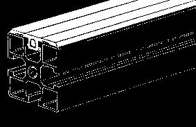
Since 1987, the NORCAN Company has been distinguished by its high-quality modular structures formed by aluminium profiles connected by standard M8
|
|
|
- Laurence Stone
- 5 years ago
- Views:
Transcription

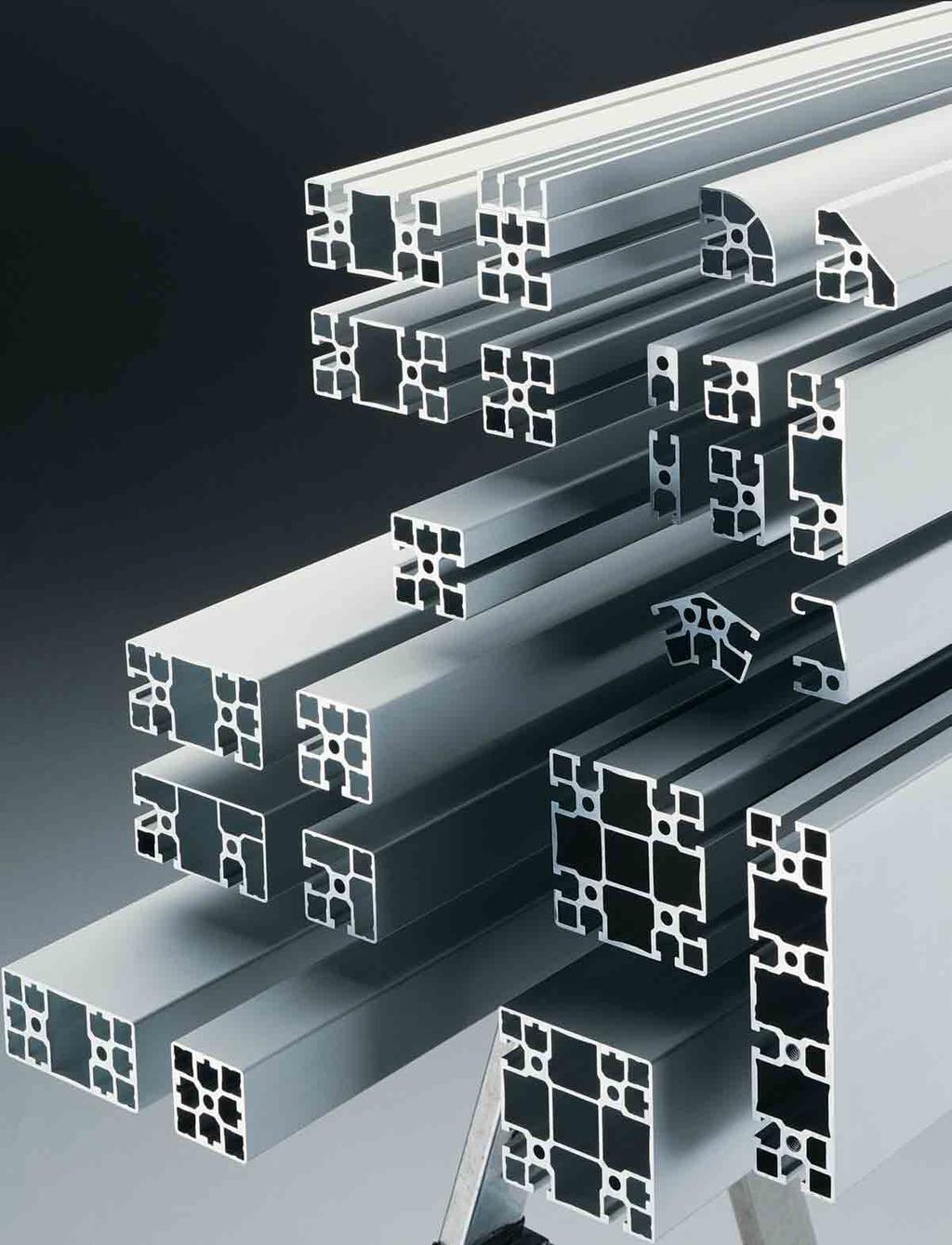
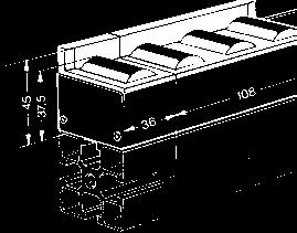
1 Since 1987, the NORCAN Company has been distinguished by its high-quality modular structures formed by aluminium profiles connected by standard M8 screw fixings: a system that is flexible in use, simple to assemble, reliable, strong and economical. 50 models of closed or grooved profiles, and more than 600 accessories fully compatible with one another, provide solutions to the most diverse construction projects in every field. The expertise of the 15 engineers in our Design Office, our high-technology manufacturing and assembly plants and our very extensive stock enable NORCAN to meet and genuinely exceed all our clients' demands. Located in Alsace close to Strasbourg, NORCAN is the leading French manufacturer of profiles, and its network of consultants on applications and integration extends throughout Europe. Our product quality and rigorous organisational procedures have enabled NORCAN to obtain ISO 9001 Version 2000 certification.

2 3


3 4 a system designed for M8 screws and nuts
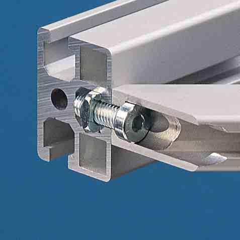
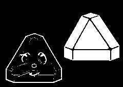
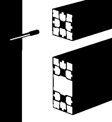
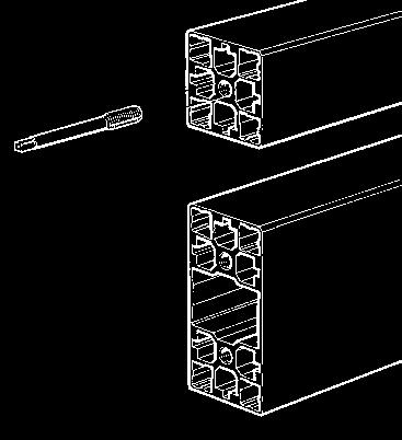
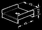
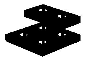
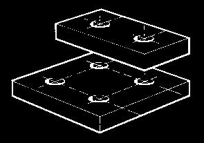
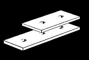
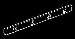
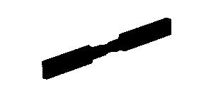
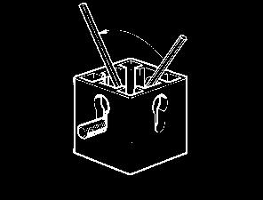
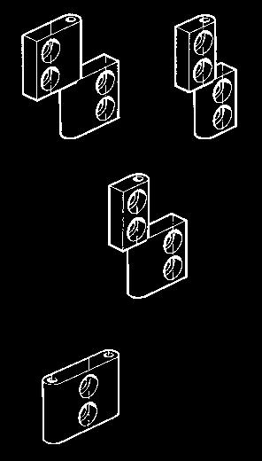
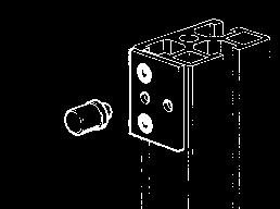
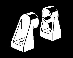
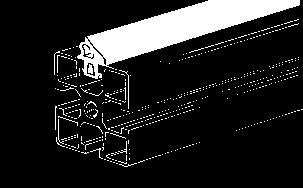
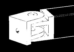
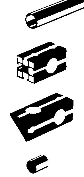
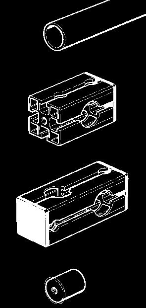
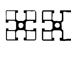
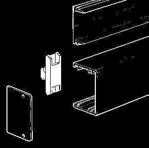
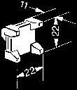
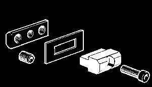
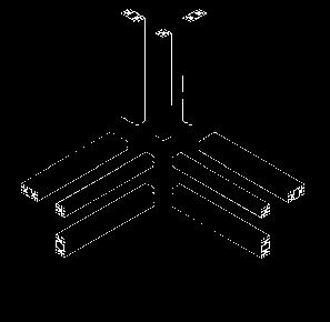
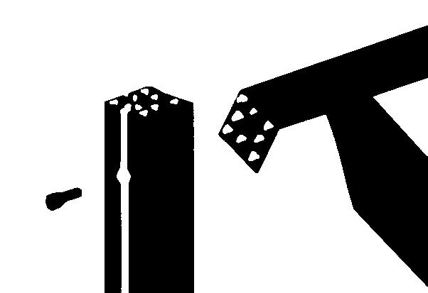
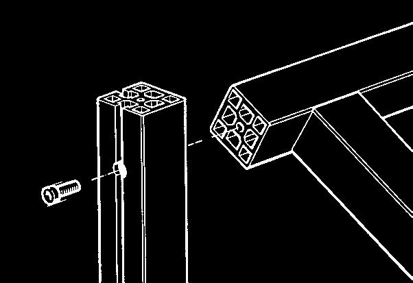
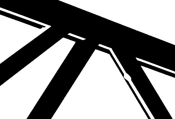
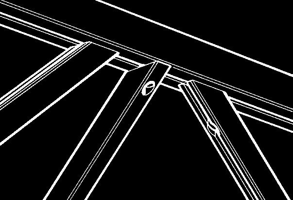
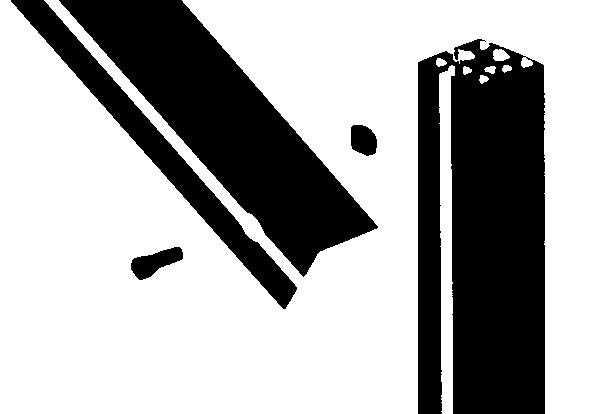
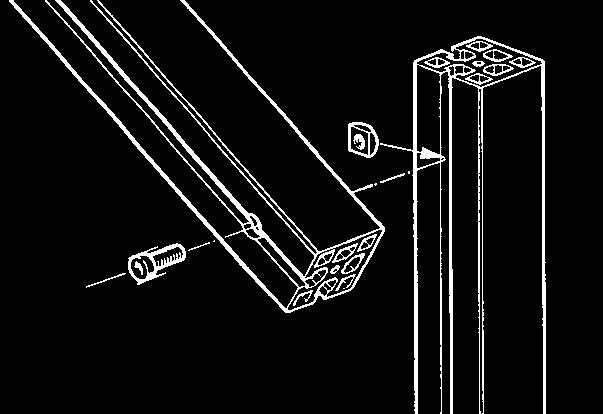
4 advantages Built around standard M8 screws and nuts Simply assembly Rigid by design Universal, modular construction and accessories 1. The grooves and slots of the NOR- CAN profiles for screws and nuts have straight parallel sides with minimal width (13,5 mm for 13 mm nuts and screwheads). Due to this, the forces from the fixing elements are directed to the centre of the profile by the shortest path. The resulting assemblies are extremely rigid and resistant. (fig. 1 and 3) The NORCAN profiles have a deep slot allowing a large end play of the screwheads and nuts (figs. 4 and 5) The M8 SC nuts with standard M8 square nut dimensions but with a chamfer can be tilted in the slot (nuts are also available in M6, M5, M4 and M3) The assembly screws are fitted to the profile through countersinks to facilitate assembly and disassembly (fig. 8) 5. The M8 tappings in the profile ends are obtained by deformation with a fluteless tap providing increased mechanical resistance (fig. 9). fluteless tap 8 9 5
")


5 summary ( = new) p30 p32 p34 p10 p10 p30 p32 p31 p31 p32 33 p11 p11 p14 p31 p34 p35 p15 p35 p31 p34 p13 p14 p12 components at scale 1/1 p16 p21 p38 p22 p25 p27 p38 p23 p26 p36 p26 p32 p39 p40 p24 p26 p28 p27 p37 p39 p41 p24 p28 p37 p41 p24 p29 p37 p40 p25 p28 p29 p38 p40 p41 6


6 summary Catalogues and software directly from p42 p43 p42 p65 p65 p44 p44 p43 p44 p45 p45 p64 p65 p66 p68 p45 p46 p45 p46 p46 p68 p69 system design aid p70 Software N_CAD and Catalogues p71 p48 p48 p68 p69 p48 p48 p47 p69 p72 p49 p46 technical chapter p49 p51 p49 p54 p67 using M8 screws and bolt C p73 electrical continuity p78 loads and deflections fitting of glass and panels p74 p79 assembly applications p76 unities p52 p57 p62 p58 61 p63 p63 p82 p88 p81 application examples p system design aid and documents p. 112 p66 p66 p66 assembly instructionsp114 alphabetic index p
7 Design and Calculations Client s sketch Project definition : Assistance and advice to define the project. Design : - Specification of machine frames, housings and other assemblies in NORCAN profiles using a specific software. -Definition of special structures - Definition of conveyors and linear guides. scale 1/10 (isometric) Calculations : Calculations of deflection and allowable loads by applications of standard mechanical engineering methods. 8


8 machining and assembly Machining : - Quality cutting to length - Milling -Lathe Work - Drilling and countersinking - Bending - Structural gluing of large section profiles. Profiles machined according to this document or our drawings are individually referenced with labels indicating reference and assembly position allowing significant time saving during assembly. Shipment of ready-to-assemble elements. Assembly : In our own workshops or at customer premises, we can carry out : - Assembly of machine frames and housings - Assembly and adjustment of conveyors - Assembly of workstations. Due the large time saving, we recommend the assembly of complex structures by NORCAN assembly personnel. Shipment of an assembled structure. 9
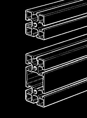
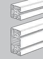
9 technical specifications of the profiles Technical specifications of NORCAN profiles Material EN AW 6060 (AI Mg Si 0,5) Finish anodised E 6 10 m - other finishes on request Elastic limit Rp 0,2= Nmm -2 (N Nmm -2 ) Shear stress Rm = Nmm -2 (N Nmm -2 ) Resistance to fatigue (polished sample, alternate bending) R f 70 Nmm -2 Modulus of elasticity E = Nmm -2 ; G = 2, Nmm -2 Thermal expansion factor K -1 Standard length 6 m Electrical continuity : For structures which require a high degree of electrical continuity we can supply profiles treated with conductive ALODINE finish. Every NORCAN profile is designed for use with standard M8 screws and bolts, the slot dimensions (width 13.5 mm) are such that every M8 screw or nut (hex and square-head screw, hex and square-head nut) can be slid along the slot while being prevented from rotating The nuts NORCAN..SC,..LSC,..RSC,..RLSC can be tilted and inserted in to the slot. M8 tappings in the profile ends are obtained by deformation, i.e. without chips ; the central hole diameter is 7.4 mm. The tool, a M8 fluteless tap is available under the reference N Weight/ Area 1) Moment of inertia 1) Polar moment linear of cut of inertia 1) [kg/m] [mm 2 ] l y [mm 4 ] l z [mm 4 ] [mm 4 ] 1) Nominal value without machining in the yz plan 7,4 for M8 Fluteless tap N , , , , N , , , Profile 45x45 closed - N 0215 : these profiles enable the building of modular structures in aluminium without visible slots, a common requirement for laboratory, food industry, pharmaceutical industry and cleanroom use. The mechanical quality of the joints together with the high torsional rigidity of these structures is to be noted. Patent N Profile 45x90 closed - N 0126 : 45x90 version of the profile N 0215, above. Patent N z x y N , , , Profile 45x45 3 sides closed - N 0283 : for structures and guarding. N , , , , Profile 45x45 half closed - N 0265 : for use in machine frames and housings with panels without visible slots. N , , , , Profile 45x90 half closed - N 0266 : 45 x 90 version of the profile N 0265 above. 10
![technical specifications of the profiles Weight/ Area 1) Moment of inertia 1) Polar moment linear of cut of inertia 1) [kg/m] [mm 2 ] l y [mm 4 ] l z [mm 4 ] [mm 4 ] 1) Nominal value without](/docs-images/81/82869638/images/10-0.jpg "machining in the yz plan N 0275 1,4 522 1,0 10 5 1,0 10 5 0,6 10 5 Profile 45x45 half closed light - N 0275 : half closed profiles for guarding and light structures. Important!")

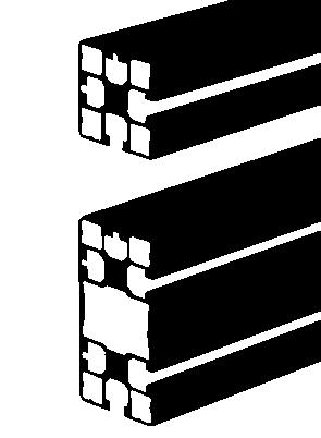
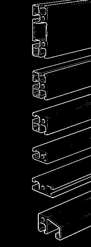
10 technical specifications of the profiles Weight/ Area 1) Moment of inertia 1) Polar moment linear of cut of inertia 1) [kg/m] [mm 2 ] l y [mm 4 ] l z [mm 4 ] [mm 4 ] 1) Nominal value without machining in the yz plan N , , , , Profile 45x45 half closed light - N 0275 : half closed profiles for guarding and light structures. Important! Only the slotted sides of the profiles are used for assembly see p N , , , , Profile 45x90 half closed light - N0276: 45 x 90 version of the profile N 0275 above. z x y 45 N , , , Profile 45 x 45 2 opposed sides closed - N 0284 : for structures and guarding. 45 z x y N , , , Profile 45 x 45 1 side closed - N 0285 : for structures and guarding N , , , Profile 45 x 90 1 side closed - N 0286 : 45x90 version of the profile N0285 above. 45 N , , , , Profile 45x45 - N 0165 : profiles for use on machine frames, tables, supports and large housings where 4 profile slots are necessary. N , , , , Profile 45x45 - N 0166 : 45x90 version of the profile N0165 above. 11
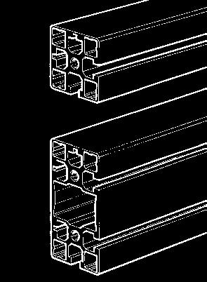
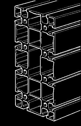
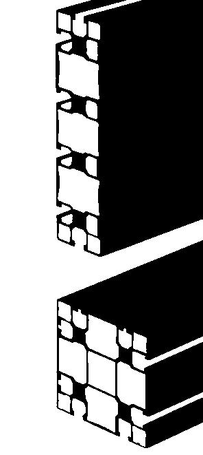
11 technical specifications of the profiles Weight/ Area 1) Moment of inertia 1) Polar moment linear of cut of inertia 1) [kg/m] [mm 2 ] l y [mm 4 ] l z [mm 4 ] [mm 4 ] 1) Nominal value without machining in the yz plan z x y N , , , , Profile 45x45 heavy - N 0115 : heavier version of the N 0165 profile. N , , , , Profile 45x90 heavy - N 0116 : heavier version of the N 0166 profile. z x y N , Profile 90x 90 half closed - N 0267 z x y N , Profile 90x 90 - N 0167 z x y N , , Profile 90x 90 heavy - N 0117 : heavier version of the N 0167 profile. 12
12 technical specifications of the profiles Weight/ Area 1) Moment of inertia 1) Polar moment linear of cut of inertia 1) [kg/m] [mm 2 ] l y [mm 4 ] l z [mm 4 ] [mm 4 ] 1) Nominal value without machining in the yz plan z x y N , , Profile 45x135 - N N , , , Profile 45x side closed heavy - N 0268 N , Profile 90x 180 heavy - N 0119 : large section profile to meet high load and stiffness specifications. Assembled profiles : for applications requiring large section profiles, NORCAN can offer certain pre-assembled profiles. For technical details and assembly details (structural bonding is possible), please consult us. 13
![technical specifications of the profiles Weight/ Area 1) Moment of inertia 1) Polar moment linear of cut of inertia 1) [kg/m] [mm 2 ] l y [mm 4 ] l z [mm 4 ] [mm 4 ] 1)](/docs-images/81/82869638/images/13-0.jpg "Nominal value without machining in the yz plan 45 N 0295 1,2 459 6,9 10 4 6,9 10 4 Profile 45x 45 triangle - N 0295 : for guarding, office and workshop furniture.")


13 technical specifications of the profiles Weight/ Area 1) Moment of inertia 1) Polar moment linear of cut of inertia 1) [kg/m] [mm 2 ] l y [mm 4 ] l z [mm 4 ] [mm 4 ] 1) Nominal value without machining in the yz plan 45 N , , , Profile 45x 45 triangle - N 0295 : for guarding, office and workshop furniture. Assembly see p N 0294 p. 29 1, , , Profile 45x45 1 / 4 round - N 0294 : for guarding, office and workshop furniture. Assembly see p p z x y 90 N , Profile 45x90 1 / 4 round - N 0296 : 45 x 90 version of the profile N 0294 above. p N , Profile 31,5x 90 - N 0264 New housing profiles : for use for protection housings, small frames and laboratory equipment. Used with closed and half closed profiles, it is possible to make attractive structures without visible slots. N , , , , Profile 31,5x 45 - N 0164 N , , , , Profile 31,5x 31,5 - N 0163 N , , , , Profile 18x 31,5 - N 0161 N , , , , Profile 18x 45 - N N , , Profile 18x 31,5 with handle - N 0261 : avoids the need for additional handles and improves rigidity and ergonomic properties of doors. End plates see p. 41.
![technical specifications of the profiles z Weight/ Area 1) Moment of inertia 1) Polar moment linear of cut of inertia 1) [kg/m] [mm 2 ] l y [mm 4 ] l z [mm 4 ] [mm 4 ] 1) Nominal value without](/docs-images/81/82869638/images/14-0.jpg "machining in the yz plan x y 38 6 10 N 0421 0,5 205 2,2 10 4 2,7 10 4 Profile for handle - N 0421 : for long handles, cut to suit. Ideal for stiffening panels of 5 or 8 mm in sliding doors see p. 41.")

 and for conveyor rails with roller units (p. 62, 63).")
14 technical specifications of the profiles z Weight/ Area 1) Moment of inertia 1) Polar moment linear of cut of inertia 1) [kg/m] [mm 2 ] l y [mm 4 ] l z [mm 4 ] [mm 4 ] 1) Nominal value without machining in the yz plan x y N , , , Profile for handle - N 0421 : for long handles, cut to suit. Ideal for stiffening panels of 5 or 8 mm in sliding doors see p ,5 p41 N , , Profile 31,5/45 - N 0195 : to assemble all NORCAN profiles at an angle of see p. 77. z x y N , p77 50/46 square tubing - N 0599 : for telescopic mountings with 45 x 45 profiles. The fixing is made with 2 pairs of M8 x 16 screws (N3133) and M8 SC or M8LSC nuts at 90. Important! Do not position the screws across the axis of the profile danger of deformation. See p. 77. z N 0869 x y 45 N , , U section profile 45x45 - N 0867 : to provide a neat solution for routing cables (p.68) and for conveyor rails with roller units (p. 62, 63). 45 p62, 63, 68 Snap in cover for U section profile - N0869 z x y N ,5 45 N , , , p62, 63, 68 U section profile 31,5x45 - N 0868 : to provide a neat solution for routing cables (p. 68) and for light conveyor rails with roller units (p. 62, 63). N , , , , Tubing ø 30 x 2 - N 0511 : multipurpose fixing and spacing element (p. 35 and 41). p35, 41 x z y N 0804 N ,2 77 0, , Lateral guide - N 0805 Slide rail - N 0804 : very light profiles for guides and light supports (p. 63) p63 15


15 Ø 7,4 for M8 fluteless tap N 0215 N 0265 N 0275 N 0216 N 0266 N 0276 N 0283 N 0294 N 0295 N 0284 N


16 N 0285 N 0165 m 16,5 n N 0115 N 0286 N 0166 N 0116 N 0162 N 0164 N 0195 N 0195 N 0161 N 0163 N
17 N 0267 N 0268 N N 0170
18 N 0119 N
19 N N0869 N N0871 N0867N N N N N , N N0511 Ø30 Ø N N N0805N Ø N0868N N N N 0411 N 0411 N 0412 N 0413 N 0421 N N N N0804N


20 curved profiles x z y Most NORCAN profiles can be curved. The drawing shows the possibilities for some NORCAN construction profiles. The profile section is only deformed a small amount and can be anodized, cut and milled afterwards. minimum radius = 220 mm N0162 minimum radius = 300 mm N0164, N0165, N0285 N0265, N0215 Curved rails for guidances : the rails for the linear guidance system NAP57 may be curved to a minimum radius of 300mm. The carriages must be individually adjusted to every rail it is necessary to contact our technical department before using these rails. R mini = 300 mm 21
21 components - fixing elements cc electrical continuity p 78 N 3145 Low-Head Screw M8 x 43 - N 3145 Grade 8.8 zinc coated - 5 mm key M8 x 45 stainless steel - N 3545 Low-Head Screw M8 x 43 Nyloc - N 3195 Tightening torque, maximum load, deflection under load, pages 73 to 75. M8 x 43 13, Standard assembly for NORCAN profiles - high static loads - excellent resistance to dynamic loads - very good stiffness


22 components - fixing elements cc electrical continuity p 78 N 3135 N 3355 N 3356 Low-Head Screw M8 x 20 - N 3135 Grade 8.8 zinc coated - 5 mm key Low-Head Screw M8 x 20 stainless steel - N 3525 Low-Head Screw M8 x 20 Nyloc - N 3185 Square washer - N 3355 zinc plated steel - provides better pressure distribution inside the slot - for hex and socket head screws, can be titled and inserted inside the slot. Square washer stainless steel - N 3555 Electrical continuity washer - N 3356 Tightening torque, maximum load, deflection under load, pages 73 to For applications where the standard assembly with the M8 x 43 throughbolt cannot be used. M8 x 25 ref. N for electrical continuity b 8 v m 54 n 9 10 m 38 n M8 x 20 (16) * M8 x 20 (16) * b b M8 x 20 (16) * *) Fig. 11, 12, 13 : M8 x 16 screw, when assembling without pressure washer and nut inside a profile slot of heavy profiles. 23
23 components - fixing elements cc electrical continuity p 78 M8 SC N 3310 Nut SC zinc plated steel - can be tilted and inserted in the slot, thus permitting the attachment of various elements to existing structures without any need for dismantling. Plastic foam retainers N 3301 help to retain the inserted screw in position in vertical slots. Spring nuts...rsc and...rlsc see on bottom of this page. M6 SC N 3309 M5 SC N 3308 M4 SC N 3307 M3 SC N 3306 M8 SC N N 3301 M8 SC - N 3310 M8 SC stainless - N 3510 M6 SC - N 3309 M5 SC - N 3308 M4 SC - N 3307 M3 SC - N 3306 Plastic foam retainer - N 3301, for fixing the nut inside vertical slots. Double nut M8 DSC - N 3315 in zinc plated steel - to be tilted in the slot. May be locked by using a M8 grub screw in one thread (figure 3). M8 SC M8 DSC... SC 1 M8 SC M6 SC M5 SC M4 SC M8 SC M6 SC M5 SC M4 SC 2 N Long nut M8 LSC - N 3312 Long version of the nut M8 SC, preferred for use in adjustable elements. M8 LSC N 3312 Material : zinc plated steel. M8 RSC N 3326 M8 RSC inox N 3526 M8 RLSC N 3316 Spring nuts, M8/6/5/4 RSC. This version of the nut incorporates a spring that maintains its position within the profile slot. M6 RSC N 3327 M5 RSC N 3328 M6 RLSC N 3317 Spring nuts, long M8/6 RLSC A long version of the SC-nut which incorporates a spring that maintains its position within the profile slot. RLSC M4 RSC N 3329 Materials : nut zinc plated steel, (N 3526 stainless steel) spring stainless steel. RSC M3 RSC N


.")
.")
![B B 1 A 2 A 3 A tighten to maximum F A [N] L [mm] F [N] f [mm] Method T1 : NORCAN 45 x 45mm fixed with 1 adjustable fixing N 1149 F A maxi = 3600 N F maxi (for L = 0) = 1800 N (F](/docs-images/81/82869638/images/24-4.jpg "L) maxi = 80 Nm f 40 10-12 FL 3 + 80 10-9 FL 2 Ex.")
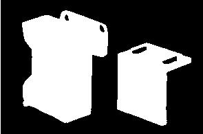
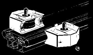
24 components - fixing elements cc electrical continuity p 78 M5 N 3304 M4 - N Quarter turn nut - for quick assembly of light parts. For parts with safety requirements please note that these nuts are not self locking in position. In these instances use M5 SC and M4 SC nuts. M5 - N 3304 M4 - N 3303 Material : zinc plated steel. N Adjustable coupling T - N 1149 : For the assembly of all closed and slotted profiles on the slot of a NORCAN profile. - Can be assembled easily -For the assembly of profiles which need to be adjustable -For the assembly of profiles where the use of a central screw is not possible, for instance crucifix mountings. - Provides electrical continuity. Assembly : screw the M8 x 25 knurled head screw into the end of the profile A (fig.1). Insert coupling into the slot of profile B (fig 2). Slide profile A into position and tighten the grub screw to its maximum (fig. 3). The adjustable coupling T is compatible with the locking finger N 1132 (p. 26). B B 1 A 2 A 3 A tighten to maximum F A [N] L [mm] F [N] f [mm] Method T1 : NORCAN 45 x 45mm fixed with 1 adjustable fixing N 1149 F A maxi = 3600 N F maxi (for L = 0) = 1800 N (F L) maxi = 80 Nm f FL FL 2 Ex. F = 100 N ; L = 1000 mm f 12 mm F A [N] L [mm] F [N] f [mm] Method T2 : NORCAN 45 x 90mm fixed with 2 adjustable fixings N 1149 F A maxi = 7200 N F maxi (for L = 0) = 3600 N (F L) maxi = 270 Nm f 5, FL FL 2 Ex. F = 100 N ; L = 1000 mm f 3 mm Maximum load on adjustable coupling T - N 1149 : These fixings are not as strong as a M8 x 43 or a M8 x 20 central screw. When occasionally overloaded to a maximum of 170 % of the values FA and (F L) the adjustable coupling deforms elastically and return into its original position once the tension is released. 25
25 components - fixing elements cc electrical continuity p 78 N1132 Locking finger - N Prevents the rotation of profiles assembled with a single central screw when subjected to high rotational torque M r. Material : zinc plated steel. M r N 1145 N 1144 N ,5 15,3 Angled assembly coupling 45 long - N 1145 with M8 x 30 screw and square washer. Angled assembly coupling 31,5 long-n 1144 with M8x30 screw and square washer. Angled assembly coupling 15,3 long - N 1143 with M8x30 screw and square washer. To allow assembly from Material : aluminium alloy. For 45 angle couplings, see page 23 and N 1140 Assembly nut - N 1140 with M8 x 30 screws and M8 SC nut. To assemble cross joints, fixed or adjustable, at right angles. Tightening via angled key N 5712, the access opening is closed with plug N Material : aluminium alloy 2 The example shows an assembly possible with M6 x 30 and M6 SC nut. 1 26
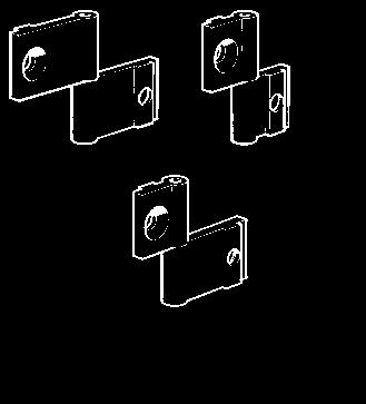
26 components - fixing elements cc electrical continuity p 78 N Steel corner triangle 16 x 40 - N 1094 Steel corner triangle 40 x 40 - N 1095 with 2 M8 x 20 screws 2 washers and 2 M8 SC nuts. Material : steel with black epoxy finish. N 1094 N1105 N1107 Corner triangle 40 x 25 - N 1105 Corner triangle 40 x 18 - N 1107 with 2 M8 x 20 screws and 2 M8 SC nuts. - facilitate the assembly of easily adjustable elements - increase the rigidity of existing structures (see assembly B... page 54 and 55) - for the assembly of various panels and elements - interconnect profiles where the central screw arrangement cannot be used. Material : anodised aluminium alloy N N1103 Heeled corner triangle 40 x 25 - N 1104 Heeled corner triangle 40 x 18 - N with 2 M8 x 20 screws and 2 M8 SC nuts. 22, for adjustable non-rotating assemblies Material : anodised aluminium alloy. N N1101 Corner triangle with 2 heels 40x25 - N1102 Corner triangle with 2 heels 40x18 - N1101 with 2 M8x20screws and 2 M8SC nuts 22, for adjustable non-rotating assemblies on two axes and the assembly of orthogonal joints using the profile slots. Material : anodised aluminium alloy. 27
27 components - fixing elements cc electrical continuity p 78 N1108 Corner triangle 87 x 85 - N 1108 : with 8 M8 x 25 screws, washers and M8 SC nuts. Angular tolerance: ±0,3 Material : cast aluminium alloy, peel shot Rp 0,2 220 Nmm -2 ; Rm 260 Nmm -2 Corner triangle 87 x 40 - N 1109 : with 4 M8 x 25 screws, washers and M8 SC nuts. Angular tolerance: ±0,3 Material : cast aluminium alloy, peel shot Rp 0,2 220 Nmm -2 ; Rm 260 Nmm -2 N 1109 N Left-hand assembly plate (marked) - N 1111 with 4 M8 x 20 screws and 4 M8 SC nuts Right-hand assembly plate - N 1110 with 4 M8 x 20 screws and 4 M8 SC nuts. These assembly plates are for right angle adjustable joints. Material : black anodised aluminium alloy. N N 1148 Adjustable coupling X - N 1148 With grub screw M8 x 12 Ideal for two axis adjustment under light load. Material : zinc plated steel. 28


![N 0294 N 0294 4 N 0294 N 0296 N 0296 5 N 0294 7 8 6 F A [N] L [mm] F [N] f [mm] F A maxi = 1800 N F](/docs-images/81/82869638/images/28-4.jpg "maxi (pour L = 0) = 1800 N (F L) maxi = 40 Nm f 40 10-12 FL 3 + 2 10-7 FL 2 Ex.")
 = 3600 N (F L) maxi = 135 Nm f 40")

28 components - fixing elements cc electrical continuity p 78 N way block with black triangular cap - N way block with grey triangular cap - N1139 : with 3 M8 x 20 screws, for the assembly of 45 x 45 triangular profiles N Material : cast aluminium alloy, PA fibreglass N way-block with black 1/ 4 round cap - N way-block with grey 1/ 4 round cap - N1138 : with 3 M8 x 20 screws for the assembly of 45 x 45!/4 round profiles N Material : cast aluminium alloy, PA fibreglass. N 0294 N N 0294 N 0296 N N F A [N] L [mm] F [N] f [mm] F A maxi = 1800 N F maxi (pour L = 0) = 1800 N (F L) maxi = 40 Nm f FL FL 2 Ex. F = 10 N; L = 1000 mm f 2,5 mm!! F A [N] L [mm] F [N] f [mm] F A maxi = 6000 N F maxi (pour L = 0) = 3600 N (F L) maxi = 135 Nm f FL FL 2 Ex. F = 100 N; L = 1000 mm f 5 mm Maximum loads on 3-way blocks : naturally, mountings with 3-way blocks cannot have the same mechanical qualities as mountings with central M8x43 or M8x20 screws (see p. 74). Where large couples exist it is necessary to reinforce the structure (fig.3) or alternatively use solutions like fig.5 and 6. The results of the tests besides show the elastic limit. 29
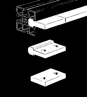
29 1 2 components - fixing elements cc electrical continuity p 78 Assembly plates with M8 x 20 screws and M8 SC nuts : 45 x 90 x 12 - N x 135 x 12 - N x 180 x 12 - N x 90 x 12 - N x 135 x 12 - N x 180 x 12 - N x 270 x 12 - N 1183 For cross mountings, axial connections, fixing on straight surfaces (fixings on the floor see anchor angles p 65 and 66), adjustable mountings and for the fixing of accessories. On request, milling and drilling to customers drawing. See : -Mounting bases (p64) -Pneumatic plates (p 69) Material : plain anodised aluminium. 3 4 N1153 N1170 Steel assembly plates with M8 x 20 screws and M8 SC nuts. 45 x 90 x 4 - N x 135 x 4 - N 1170 Economic alternative to plain aluminium plates, essentially for moderate loads. Material : steel with black epoxy coating. 30
30 components - fixing elements and accessories cc electrical continuity p 78 N1137 Connecting bar - N 1137 with 4 grub screws for axial connection of profiles under low load. Material : zinc plated steel. 1 N1130 Angle connection bar - N 1130 with 4 grub screws for end-to-end joints and angle joints under low load. Material : zinc plated steel N Way block - N 1125 with 5 M8 x 20 screws and 1 endplate 45 x 45 N For crossover assembly under a moderate deflectional load. Important! For special applications, some crossover junctions with a central screw, practically invisible from the outside, are possible. Details on application. N 1141 M8 x 43 Assembly nut, double - N 1141 with M8 x 43 screw for end-to-end fixing of profiles under low load Material : aluminium alloy 31
31 components - fixing elements and accessories cc electrical continuity p 78 x z Tighten these two screws y N 1117 Pivot 45 x 45 - N 1117 with 2 low head screws M8 x 20 mm. Fits on either the cut end or the side of the profile. For fixed angle mountings from +90 to -90. Maximum torque around the y-axis : 135 Nm (elastic limit). Material : aluminium alloy anodised black. To prevent the pivot from turning around its fixing screw use an antirotation plate N x z y N 1127 Pivot 45 x 45, dynamic - N 1127 with 2 low head screws M8 x 20 mm. Fits on either the cut end or the side of the profile. For dynamic mountings from +90 to -90. Maximum torque around the y-axis : 135 Nm (elastic limit). Material : aluminium alloy anodised black. To prevent the pivot from turning around its fixing screw use an antirotation plate N x z y Pivot 45 x 45 with locking handle - N 1120 with 2 low head screws M8 x 20 mm. Fits on either the cut end or the side of the profile. For fixed angle mountings from +90 to -90. Maximum torque around the y-axis : 135 Nm (elastic limit). Tightening the handle with 20 Nm will lock the pivot with about 45 Nm. Material : aluminium alloy anodised black To prevent the pivot from turning around its fixing screw use an antirotation plate N N 1120 N 1129 Antirotation plate - N 1129 : to prevent profiles and accessories of 45 mm width from turning around the axis of their fixing screw. Elastic limit : M r = 80 Nm Material : 1,5 mm stainless steel. thick 1,5 M r x z N 1147 y 35 Pivot 45X90 - N1147 with 2 low head screws M8 x 20. Fits on either the cut end or the side of the profile. For fixed angle mountings from +90 to -90. Maximum torque around the x-axis (sliding of the M8x20 screw): 81 Nm. Maximum torque around the y-axis: 230 Nm. Material: Aluminium alloy anodized black
32 components - fixing elements and accessories cc electrical continuity p 78 N 1128 Pivot 45x90, dynamic - N 1128 : with 2 low head screws M8 x 20. Fits on either the cut end or the side of the profile. For dynamic angle mountings from + 90 to Maximum torque around the x-axis (sliding of the M8 x 20 screw) : 81 Nm. x z y 35 Maximum torque around the y-axis : 230 Nm. Material : Aluminium alloy anodized black x z y 35 N 1136 Pivot 45x90 with locking handle - N 1136 : with 2 low had screws M8 x 20. Fits on either the cut end or the side of the profile. For angle mountings from + 90 to Tightening the handle with 20 Nm will lock the pivot with about 45 Nm. Maximum torque around the x-axis (sliding of the M8 x 20 screw): 81 Nm. Maximum torque around the y-axis : 230 Nm. Material : Aluminium alloy anodized black, handle PA black
33 components - fixing elements and accessories cc electrical continuity p 78 N mm thick Steel adjustable plate - N 1545 with screws and nuts for shelves and other adjustable assemblies. Tightening the screw with 20 Nm will lock the plate with about 160 Nm. Material : steel with black epoxy coating. N 1544 Plate, footrest, adjustable N 1544 with 3 M8 x 20 screws, 2 M8 SC nuts 3, washers and 1 locking finger. The profile A can be adjusted from 0 and 45. Tightening the screw with 20 Nm will lock the plate with about 160 Nm. Material : plain anodised aluminium. A N Aluminium adjustable plate N 1546 with 3 M8 x 20 screws, M8 SC nuts and washers. For adjustable structures, accessories, conveyors etc. Tightening the screw with 20 Nm will lock the plate with about 160 Nm. Material : plain anodised aluminium
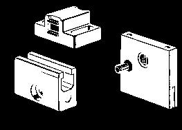
34 components - fixing elements and accessories cc electrical continuity p 78 for M6 bolts Sensor-support - N 1412 : adjustable support for photocells, limit-switches and other types of switches with a diameter of 19 mm used for automation. Material : black polyamide, tubings stainless steel or anodised aluminium. tube length : 150 mm N 1412 N 1450 N 1452 N 0511 tightening screw Tubing 30 x 26 - N 0511 anodised aluminium. Weight per linear meter : 0,475 kg/m for a section of 175 mm 2 Inertia (deflection) : 1, mm 4 Inertia (twisting) : 3, mm 4 These tubes can be used as fixing and spacing elements and are low cost and multipurpose. For connection to NORCAN profiles and interconnection between them, we currently offer the three following components. Other connection parts are available on request. Mounting Block for tubing Ø 30 - N 1450 : made from 45 x 45 mm NORCAN profile - tightening of the tube with a M8 x 20 screw and nut on the profile open side, and direct fixing on NORCAN profile with a M8 x 43 screw or with a screw in the tapped end. Cross mounting Block - N 1452 : made from 45 x 45 NORCAN profile - the tube is clamped to the profile with a M8 x 20 screw and nut. It can be fitted to other profiles by replacing this screw with a M8 x 43 screw. Tapped Plug - N 1460 : in aluminium - For gluing in the end of the tube. Allows the tube to be fitted with a screw for mounting in the profile slots. N 1460 p41 35
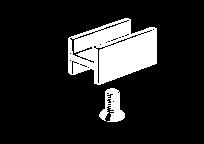
35 components - fixing elements and accessories N 1405 N 1407 Hinges with 4 M8 x 20 screws and M8 SC nuts : consist of two plates in aluminium and one zinc plated steel shaft. The hinges can face left or right and the shaft is locked when assembling. Scale drawing on page 95. N centre distance 46 mm N centre distance 32,5 mm N centre distance 19 mm N 1406 Double hinge plate - N 1409 with 2 M8 x 20 screws and 2 M8 SC nuts (pin, shaft) for assembly of juxtapositioned hinges on a central 45 mm upright (see fig. 9 below). N 1409 Important! For the design of doors and windows, see our technical section «doors and windows» p N N 1406 N LH hinge RH hinge removable door non-removable door standard clearance 4 5 mm standard clearance 10 mm stop > 20
36 components - fixing elements and accessories N 1385 Hinges, blind with 2 M8 x 16 screws and M8 SC nuts : consist of two plates in aluminium and one zinc plated steel shaft. The hinges can face left or right and the shaft is locked when assembling. N centre distance 56 mm (fig. 4) N centre dist. 42,5 mm (fig. 3) N centre distance 29 mm (fig. 2) N N 1386 N 1387 N 1386 N N0702 Door sealing strip - N 0702 Seal profile for opening doors - can be used as a stop for sliding doors or carriages of linear guidance systems. Available in 20 m length. Material : black nitrile rubber. Important : doors with seal profiles should alway be equipped with a lock, large doors with 2 or 3 locks or a locking handle with rod N 1426 (p. 40) N0703 Door sealing strip, off-centre N 0703 Seal profile for opening doors Available in 20 m length. Material : black nitrile rubber. 37
37 components - accessories N 1474 Door stop with buffer - N 1474 : with 2 low head screws M8 x 20 mm and 2 M8 SC nuts for opening doors. Material : plain anodised aluminium. N 1413 Door stop with ball latch - N 1413 : with 2 low head screws M8 x 20 mm and 2 M8 SC nuts for 31,5 (18) mm thick opening doors in 45 (31,5) mm thick frames. Material : plain anodised aluminium, latch in steel. Ball latch see page N 1416 N 1417 N 1420 Catch double sided magnet - N 1416 : with 2 M6 screws and 2 M6 SC nuts. Receptacle with M5 stud and M5 SC nut. Magnetic force 15 and 30 N. Material : black polyamide. Support for double sided magnet - N 1417 : with M8 x 25 screw and M8 SC nut. Material : black anodised aluminium. Catch, magnetic for 8 mm slot - N 1420 : for assemblies like fig. 4 below. Receptacle : M5 screw. Material : HD polyethylene Important! after positioning, fully tighten the screws B. Self adhesive receptacle for N N 1441 stainless steel sheet 12 x 60 x 1 mm with adhesive tape. N 3310 N 3133 N 1416 N 1416 N 1416 N 1416 N N N 1417 N 1417 N


.")
. Key retained.")

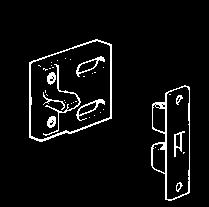
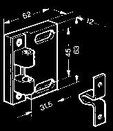
38 components - accessories N 1478 Door stop, simple - N 1478 Door stop, double - N 1479 with two grub screws and two M8 SC nuts. For 18 mm thick doors. Material : clear polycarbonate. N 1479 Door stop, L-shaped - N 1473 : for 18 mm thick doors in 31,5 mm thick frames and and 31,5 mm thick doors in 45 mm thick frames. Material : black polyamide. N 1473 N N Safety Switch Schmersal AZ 15 - ZVRK - 30N - N 1512 with nuts, screws and magnet (switch key entered = 1 contact closed). Retaining force 30 N. Safety Switch Schmersal AZ ZVRK - 30N - N 1513 with nuts, screws and magnet (switch key entered = 1 contact open, 2 contacts closed). Retaining force 30 N. Safety Switch Trojan 2NF - 1NO 1501 with nuts, screws and key (switch key entered = 1 contact open, 1 contact closed ). Key retained. Safety Switch Trojan 2NF - 1NO 1500 with nuts, screws and key (switch key entered = 1 contact open, 2 contacts closed). With kit for key retainer. Fastener for safety switch key - N 1511 with nuts and screws. Fastener for safety switch - N 1510 with nuts and screws. For assembly of these components on slotted profiles, we recommend NORCAN SC nuts M4 SC - N 3307 and M5 SC - N N 1510 N 1510 N


.")
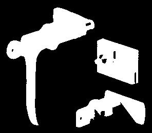
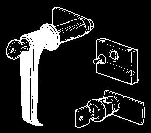
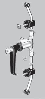
39 components - accessories N 1425 N Locking handle - N 1425 : 22 for profiles, 18 mm, 31,5 mm and 45 mm thick. Latch lock - N 1430 : 20 for safety housing profiles. Lock for sliding doors - N 1438 : with fixing plate, nuts and bolts. N 1438 N 1430 N 1426 Locking handle with rod - N 1426 : 22 mm, for 18, 31,5, and 45 mm thick doors. The rods are 1000 mm long and have to be cut to suit. Material : polyamide / zamak / zinc coated steel. Assembly : according to the sequence of assembly q to t indicated on the right hand drawing. Bending and adjusting the rod is the last step. 10 Ball latch - N 1422 with stainless steel plate and screws and nuts. For doors of moderate size (up to 0,5 m 2 ). Two ball latches should be mounted per door in a 9,8/12 counterbore, 3 mm deep. For larger and heavier doors use ball latch 2 N 1413 p 26. N 1422 counterbore ø 9,8 / 12 prof. 3 40
40 components - fixing elements and accessories N1761 N 0261 thick 2,5 N1721 N 0421 Pair of endplates for handle profile 18 x 31,5 - N 1761 Handle profile - N 0261 : makes the handle part of the structure of safety housing doors. Material : anodised aluminium. Length : 6 m or cut to suit. Pair of endplates for handle - N 1721 Material : grey ABS. Profile for handle - N 0421 : for long door handles cut to suit. Ideal for stiffening panels of 5 and 8 mm in sliding doors. Mounted with M6 screws. Material : anodised aluminium. Length : 6 m or cut to measure. N 0261 N (21) N 1440 (N 1442) N1444 Handle 116 CTRS - N 1440 with two M8 x 20 screws and two M8 SC nuts. Fits on 45 x 45 and 45 x 90 mm NORCAN profiles. Material : black polyamide. Width 25 mm, over all length 139 mm. Handle 92 CTRS - N 1442 with two M6 x 20 screws and hex nuts. Fits on 18 x 31,5 and 31,5 x 31,5 mm NORCAN profiles. Material : black polyamide. Width 21 mm, over all length 116 mm. Closed handle - N 1444 with 2 screws M6 x 20, 2 hex nuts M6 and 2 square washers. Can be fitted to all NORCAN structures, panels and glass panels. Material : plan anodised aluminium. End plates black ABS. Important : the square washers 13 x13 x 2 mm are used only for assembly into a profile slot. N1447 N1448 End support for ø 30 tubing N 1447 with screws and nuts. Central support for ø 30 tubing N 1448 with screws and nuts. For custom made handles with anodised aluminium tubing 30 N Material : PA with glass fibre. p23 41
41 components - accessories Panels cut and machined to suit N melamine panel white 8 mm 1) N melamine panel white 19 mm N melamine panel beige 8 mm 2) N melamine panel beige 19 mm N plywood 18 mm 3) N plywood 22 mm N compound grey 8 mm N foam PVC white 5 mm 4) N foam PVC white 8 mm 5) N acrylic clear 5 mm 6) N acrylic clear 8 mm N acrylic smoked 5 mm N acrylic smoked 8 mm N polycarbonate clear 4 mm N polycarbonate clear 5 mm N polycarbonate clear 8 mm N polycarbonate smoked 4 mm N polycarbonate smoked 5 mm N polycarbonate smoked 8 mm N aluminium anod. 2 mm 7) N aluminium non anod. 4 mm 8) N aluminium non anod. 5 mm N aluminium non anod. 8 mm 8) N aluminium non anod. 12 mm N aluminium non anod. 20 mm N wire mesh welded, black 9) 40/40 4 mm N wire mesh welded, zinc coated 40/40 4 mm Rough size of the panels 1) 2650 x 2070 mm 6) 3050 x 2050 mm 2) 2850 x 2070 mm 7) 4000 x 1500 mm 3) 3050 x 1530 mm 8) 2000 x 1000 mm 4) 3050 x 1220 mm 9) 2000 x 1600 mm 5) 3050 x 1560 mm On request : special colours, glass panels, painted or stainless steel sheet. Electronic industry : conductive panels resistant to hot solder. Panel dimensions according to type of mounting : Hp ±1 Lp ±1 Panel on N 1400 and N 1398 H - 2 L - 2 Panel on off centre retainer N 1402 H - 5 L - 5 Panel 19 mm on M8 or M6 setscrews or panel fixing pad N 1404 H - 1 L - 1 Panel 8 mm in slot and panel mm with N 0714 H ) L+ 27 Panel 8 mm in slot - removable, on nut at bottom of profile slot H + 10 Panel mm on N N 0714 H - 6 L - 6 Sliding panel 5 mm in N track profile H - 11 Sliding panel 8 mm in 2 or 3-track, (N 0412 or N 0411) non removable panel H ) Ditto but removable (sliding on 8 Ø spacer) - caution : min H P 350 mm H ) Fixing block!/4 turn N 1399 H - 12 L - 12 Wire mesh on U type profile for wire mesh - N 0724 H + 24 L+ 24 1) when using the pad N 1345 reduce Hp 2 mm. N < 2 Mounting strip - N 0714, to hold plates and glasses 2 to 5 mm thick in position inside the slot (for plates under 2 mm use 2 strips!). Material : black nitrile rubber, available in 50 m rolls. Lubricated with paraffin oil mix. Important! To be inserted after mounting the panels. Cut to length without stretching! < 2 N 0714 n N 0717 n Mounting profile - N 0717 allows assembly and disassembly of glass panels and other panels from 5 to 8 mm inside existing frames without dismantling the frames. Material : black nitrile rubber. Lubricated with paraffin oil mix. Important : the mounting profile N 0717 has always to be combined with a mounting tape N0714 of the same length which has to be ordered separately N ,5 b v N
42 components - fixing elements and accessories N 0724 U type profile for wire mesh - N 0724 : for fixing wire mesh ø 3 4 in the slots of NORCAN profiles. Material: grey PP. Length: 3m. N 0710 Sealing strip PE foam for wire mesh - N 0710 : for dust proof sealing of wire mesh protections. Material : PE foam (closed cellular construction). Important : first mount the PE strip on the wire mesh, then position the wire mesh inside the slot and finally push down the sealing strip to its final position. Panel fixing block!/4 turn - N 1399 : for mm thick panels on the slotted profile side. Assembly without tools, dismantling with a small screw-driver or similar. Material : black polyamide. N ,5 N 1398 Fixing block!/4 turn - N 1398 : for fixing mm thick panels on the slotted sides of profiles N 0163, N 0164, N 0195, N 0264 and mm panels on the slotted side of any other NORCAN profiles. Material : black polyamide. 0,5 43
43 components - fixing elements and accessories N 1404 Panel fixing pad - N 1404 with 4 mm panel screw for mounting panels 19 to 22 mm thick. Maximum static load : 0,5 kn with wood and chip panel, 1kN with aluminium plates. Material : polyamide with 15 % fibreglass, black. Mounting block - N 1400 with M8 x 30 screw and M8 SC nut. For mounting various panels and elements, height adjustable from 0 to 16 mm. Material : aluminium alloy. N 1400 N 1402 Off centre retainer - N 1402 for fast assembly of panels and glasses 1 to 8 mm thick without drilling, in particular on closed profiles. Material : mounting angle in anodised aluminium, retainer in PA mm mm mm N 1402 N 1400 N panel screw 4 x 20 N 0701 Cover strip - N 0701 for all slotted NORCAN profiles. Ideal for retaining 1 mm stainless sheet steel on work station tables. Material : antistatic (conductive) nitrile rubber Can be reduce to a width of 28 or 16 mm without tools. N 1860 q Door stop with out 33,5 n Kit 1 for quick removal of panels - N 1860 With screws and nuts. For access panels on housings. The panel can be fitted and removed with a single captive screw. To avoid their rotation, the parts 1 should always rest on a profile, hinge, etc. otherwise see N 1859 p. 45. Important! After adjustment, on first fitting, the locking screws at B must be fully tightened. B B Door stop with nut - N 1419 Slot mounting. (Without parts 1, screws and nuts). 1 44
44 components - fixing elements and accessories N Portes-écrou q B B Kit 2 for quick removal of panels - N 1859 : with screws and nuts and 2 door stops with nuts. Same application as N The parts 1 are prevented from rotation by two fixing screws and unlike N 1860 can be fitted without resting on another piece. Important : after adjustment, on first fitting the locking screws at B must be fully tightened. N 0413 Guide profile 2 tracks 5 mm N 0413 Material : anodised aluminium alloy. for a fit with no clearance, slightly deform the material as shown. N 0412 N 0517 N 0411 Guide profile 2 tracks 8 mm - N 0412 Guide profile 3 tracks 8 mm - N 0411 For 8 mm panels. Inserting ø 8 tubing N 0517 in the lower slots allows removal of glass higher than 350 mm without dismantling the frame. Material : anodised aluminium alloy. for a fit with no clearance, slightly deform the material as shown. > 350 N1345 ø20 Pad for 8 mm sliding doors - N 1345 : self lubricating. To reduce friction and to avoid jamming of sliding doors. Material : HD-polyethylene. N 1480 Guiding Finger - N 1480 : For easily removable sliding frames. Can be pulled back after loosening the locking screw Material : polyamide, black. Screw zinc plated steel. Application examples see p
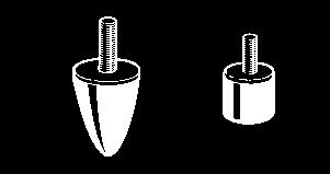
45 components N 1348 Guiding pad on M8 screw - N 1348 For sliding and folding doors. Material : polyethylene black. Important! fix the screw with thread sealant. stop > 20 N 0820 N 1307 Double door rail - N 0820 Roller for double door rail - N 1307 For sliding doors - maximum load 100 N per roller. Material : rail : plain aluminium, roller : zinc plated steel. Lower guide : guiding finger N 1480 in guide profile 3 tracks N 0411 (page 45). N 1480 N 0411 N 1484 (N 1483) 23 (18) 40 (30) N 1485 Ø M8 (Ø M6) Ø M Buffer, conical ø 25 x 30 - N 1483 Buffer, conical ø 30 x 40 - N 1484 Buffer, cylindrical ø 15 x 15 - N 1485 For stop devices on sliding doors and linear guidance carriages. Material : SBR rubber, 60/65 Shore A, screw bichromated. 30 (25) 15 N1465 N N1468 Counterbalance for vertical sliding panels : consists of a length of 45 x 90 mm NORCAN profile equipped with a pulley and suspended counterweight. For low cost construction or sliding doors made of polycarbonate 8 mm thick. N 1465 : Roller box, complete with end plate and cord. Please note two sets are required per door. Important! please note that 2 sets are required per door! N 1468 : 1 kg - counterweight with hooks (Up to 8 counterweights can be joined together. Material: Lead, black epoxy/polyester coating. N 1464 : Roller box end stop. For heavier loads contact our technical department. 46
46 components N1565 Counterbalance with chain - N1565 : for vertical sliding panels. Consists of a length of 45x90mm NORCAN profile equipped with a pulley and 2m of 8mm chain with, on one side, a stainless steel fixing for 8mm panels or a guide profile N 1347 and, on the other side a spring for attaching up to 8 counterweights of 1kg N1468. Important : please note that 2 sets are required per door! Counterweight - N1468 1kg counterweight with 2 hooks (up to 8 counterweights can be joined together). Material: Lead, black epoxy/polyester coating. End stops : see Buffers p Large sliding door with buffers N1485. N1468 N1565 N1485 N1721 Large sliding doors may be stiffened with profiles for handles N0421 (end caps N1721). N 0421 To avoid the crabbing or jamming of sliding panels, especially if the ratio of height to width is smaller than 0,7 the panel should be equipped with ball bearings N1305 or pads for sliding doors N1345 to assure a smooth linear guidance. N1315 N1345 N Guide profile for sliding doors - N1347 : with 2M8x20 screws and 2 washers, for vertical sliding doors framed in NORCAN profiles. Material: black HDPE
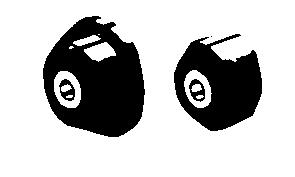
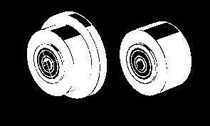
47 linear guidance systems N 1302 N 1301 Shouldered Linear Guide Roller - N 1302 : Roller in PA 6.6 on two bearings and secured by central bolt M8. Linear Guide Roller - N 1301 : Roller in PA 6.6 on two bearings and secured by central bolt M8. Maximum radial load < 400 N/security factor Maximum speed < 100 m/min Speed x load 6000 Nm/min N 1301 N 1302 N 1315 Ball Bearing - N 1315 : with 1 M8x25 screw, 1M8SC nut and 1 washer M8 16. for linear guides, can be fitted using M8 screws on all NORCAN profiles. Maximum radial load: 100N. N 1357 Guide profile - N 1357 : To hang objects, for example electric or pneumatic tools on a workstation. Material : black polyethylene. 12 Snap hook - N 1358 : Length 60 mm, steel 6 mm. Material : steel, zinc-coated. N 1358 N 1362 H-section guide block - N 1362 : with 1 M8x16F screw and 1M8SC nut. For double sliding doors made of 18x31,5 mm NORCAN profile sliding on the 45 mm slotted side of any NORCAN profile. Material : HD polyethylene, black. 48
48 linear guidance systems N 1355 N 1361 Guide profiles in high density polyethylene, black. To make guide rails using the slot in NORCAN profiles. N 1361 : Length 500 mm, mainly to produce special parts. N 1355 : As N 1361, but length 50 mm. N ,5 N 1356 : with 2 M8x20 screws, 2 M9SC nuts and 2 washers M8 16. For linear guides, fixed side, and sliding windows (see p. 80). N 1346 N 1346 : with 2 M8x20 screws and 2 washers M8 16. For linear guides, free side, and sliding windows (see p. 80). fixed side free side 1 (clearance) 2 N 1350 Guide profile 1350 : For linear guides, must be locked with a screw through the profile. N 1351 : As N 1350, but length 500 mm. floating assembly clearance : ± 0,3 *) 3,5 mm for outer side profile N 0115, N 0116, N 0117, N 0268 tightening screw M8 x 12 (clearance) N 1360 N 1360 : with 1M8x25 screw. For sliding windows. Important : Do not tighten the M6 fixing screw, use thread sealant. Don t tighten this screwuse thread sealant N
49 comparison of NORCAN linear guides 0,2 kn F 0z 3 kn without play 0,8 kn 12 kn F 0z Smooth guides PE (p. 51) : economical and robust linear guidance, particularly shock resistant in the z direction (3kN). Ideal for combinations with trapezoidal screw drives. Life: limited by the wear of the most loaded guide see p.51. Lubrication: without Coefficient of friction: 0,1. F 0y = ±0,4 kn Maximum static load on 1 smooth guide PE. The loads are cumulative. Maximum centered load on a carriage with 4 smooth guides PE. The loads are not cumulative. Off centre loads see p. 51. F 0z = ±0,2 kn without play F 0z = ±0,8kN without play Linear guidance systems on polyester rollers NAP57 (p. 52) : guidance without play, smooth and silent in operation running on anodized aluminium rails. Life: see p.53. Play: adjustable without play. Lubrication: without. Speed: dependant on the load, up to 5 m/s. F 0y = ±0,5 kn without play Maximum static load on 1 roller NAP 57. The loads may not be combined and F 0y + 2,5 F 0z 0,5 kn F 0y = ±1 kn without play Maximum centred load on a carriage with 4 rollers NAP57. The loads may not be combined. Off centre loads see p. 53. F 0z = ±1 kn without play F 0z = ±4 kn without play Linear guidance system on cassettes with steel rollers K12 (p. 54) : rigid guidance without play on hardened steel rails. Life: see p.56. Play: adjustable without play. Lubrication: assured by incorporated felt type scraping seals to be re-oiled regularly with VG220 type oil. F 0y = -1,8 kn without play F 0y = ±3,6 kn without play Maximum static load on 1 cassette K12. The loads may not be combined and F 0y + 1,8 F 0z 1,8 kn 50 Maximum centred load on a carriage with 4 cassettes K12. The loads may not be cumulated. Off centre loads see p. 56.
50 M6 x 25 smooth guides PE N 1363 Smooth guide - N 1363 : For robust and particularly shock resistant linear guidance systems. Ideal for combinations with trapezoidal screw drives. For clearance free linear guides utilise the types NAP 57 (p. 52), K12 (p. 54) and LF (p. 57). Important! To adjust the clearance by means of the M6 x 20 screw, use at least one screw adjusting bore per slot of the guidance profile (see picture below). The tight antivibration thread in the triple nut prevents the M6 x 20 screw from loosening. z x y screw adjusting bore 1 Mounting possibilities of smooth guides - N X: avoid these mountings : There are unsufficient adjustement possibilities in case of unfavourable tolerances. 3 F0(1) = 3kN F0(2) = 0,2kN F0(3) = 0,2kN Technical specifications : Material : Polyethylene black/clear. Coefficients of friction : m 0,08 ; m 0 0,12 for F 0 (1) after wearing in. Static loads : see fig. 3, the indicated values may be cumulated. Life : during a series of tests without lubrication under a closed housing we measured a wear of 0,1 mm/1000 km under a load of 0,6 (0,9) N/mm 2 at a speed of 1,4 m/s. The circular anodised test track did not show any wear. This corresponds roughly to load F 0 (1) F 0 (2) 20 N and F 0 (3) 200 N. Play : adjustable in the z axis, 0,4mm in the y axis. Assembly: 1. Position the triple nuts in the slots of the carriage and tighten the M8 grub screws. 2. Assemble the clear PE-plate and the black PE guide profile and leave about 1 mm clearance under the M6 x 20 screw. 3. Slide the carriage into the slots of the aluminium guidance profile. 4. Adjust the clearance by passing a key through the screw adjusting bores. 51


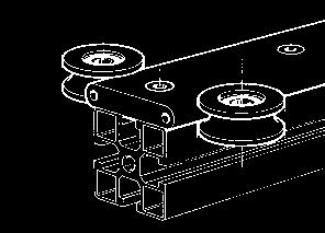
51 linear guidance systems on polyester rollers NAP 57 N 1900 N 1901 The NAP linear guides consist of an anodised aluminium alloy rail and a 2 or 4 wheeled carriage. Smooth and silent in use, the rollers on shielded ball bearings can be fitted to plates or directly to the NORCAN profiles. Rail NAP 57 - N 1901 : In plain anodised aluminium alloy. Length according to customer specification, maximum length 6 m, distance between drillings 90 mm. Supplied without screws and nuts. Polyester roller NAP 57 - N 1900 : without shaft on ball bearing. Polyester roller NAP 57 - N 1903 : with concentric shaft on ball bearing. Polyester roller NAP 57 - N 1904 : with eccentric shaft on ball bearing. Stop for NAP 57 - N 1908 : with 2 screws M6 x 20 : For fixing on the end of the rail N Material : anodised aluminium alloy with rubber buffers. N 1905 N 1910 : with wing nut stop system N 1906 : without stop system N 1901 N 1908 N 1916 NAP 57 with 2 rollers - N Wheeled carriage, one adjustable by eccentric shaft. NAP 57 with 4 rollers - N Wheeled carriage, two adjustable by eccentric shaft. NAP 57 with 4 rollers with stop - N 1910 Free play adjustment : Even through the N 1904 pulleys are eccentric to allow take up of free play, the carriages are not intended for use under preload. Carriage NAP57 with 4 rollers for curved rails - N 1916 : for all applications with curved rails (minimum radius: 300 mm) contact our technical department. m=0,2 kg m = 0,9 kg 8,4 / 13,5 / 5,5 prof. N 1901 N 1908 N 1905 N 1906 N 1904 N mm spanner 4 mm hexagon socket head screw Circlips side Circlips side 52
![linear guidance systems on Polyester rollers NAP 57 F ax [N] F rad 200 500 160 400 120 300 80 200 40 100 load on a roller (F ax and F rad are not cumulative) x 60 m/min. x 120 m/min.](/docs-images/81/82869638/images/52-0.jpg "x 120 m/min. 5000 10000 15000 km Life in km before appearance of pittings on the radial roller. Life and allowable loads : The table opposite represents the results of a series of tests.")


52 linear guidance systems on Polyester rollers NAP 57 F ax [N] F rad load on a roller (F ax and F rad are not cumulative) x 60 m/min. x 120 m/min. x 120 m/min km Life in km before appearance of pittings on the radial roller. Life and allowable loads : The table opposite represents the results of a series of tests. These tests were undertaken without lubrication under a closed housing The loads F ax and F rad are not cumulatives. For instance an axial force F ax = 40 N will cause an equivalent wear as a radial force of F rad = 100 N. In general : F rad equivalent 2,5 F ax + F rad The test rail did not show any wear after 10 8 cycles. Example 1 Example 1 : a roller is loaded with an axial force F ax = 60 N and a radial force of F rad = 100 N at a speed of 120 m/min. The equivalent radial force : F rad equivalent 2,5 60 N N = 250 N For this loading the test rollers achieved a life of km. Example 2 Example 2 : For the carriage opposite there is a static force, F y = 240 N acting on a point 7,5 mm above the centre of the carriage, v = 2 m/s. Radial force : The load F y will act equally on roller 1 and 3 F y = F rad 1 + F rad 3 = 2 F rad 1 F rad 1 =!/2 Fy =!/2 240 N = 120 N Axial force : At the same time F y results in a moment, M x = 30 mm F y which causes the following axial loading on the rollers : z x y F ax 1 = F ax 2 =!/2 Fy 30 mm = 50 mm 30 mm =!/2 240 N =72 N 50 mm The most loaded rollers are thus rollers 1 and 3, which see an axial force of F ax = 72 N together with a radial force of F rad = 120 N. The equivalent loading is : F rad equivalent 2,5 F ax + F rad = 2,5 72 N N = 300 N Interpolation from the test result the life would be approximately 7000 km. Assembly : First mount the rollers with eccentric shafts. Screw in that shaft completely whilst holding the nut with a #13 spanner. Then undo the shaft about a half turn into the position maximum play. Tighten the nut very slightly. Mount and tighten the rollers with concentric shafts. Adjusting : With a #13 flat spanner hold the nut of the roller with eccentric shaft and eliminate the play when turning the shaft with a #4 Allen wrench. Hold the Allen wrench in this position and firmly tighten the nut with the #13 flat spanner. A correct preload is attained when the roller can just be turned by hand, the carriage being blocked. 53
53 linear guidance systems on steel rollers K12 N 1920 N 1930 N 0830 The linear guidance system K12 consists of steel guide rails hardened to 60 HRC fitted into the slot of NORCAN profiles and steel rollers on shielded (zz) bearings individually protected and lubricated by cassettes of PA compound. The lubricators allow to re-oil the felt-type scraping seals (don t use grease!). The examples below show some basic mounting methods of K12 cassettes onto NORCAN profiles. The anti-rotation strips incorporated to allow accurate mounting can be removed easily if required. K 12 cassette with roller and concentric shaft - N 1920 : with M8 SC nut. C W ( m) = 8,3 kn ; P O see Forces p. 42. Material : polyamide, black, with 15 % glass fibre. K 12 cassette with roller and eccentric shaft - N 1930 : with M8 SC nut. C W ( m) = 8,3 kn ; P O see Forces p. 42. Material : polyamide, black, with 15 % glass fibre. The eccentric shaft allows take up of free play (± 1 mm) hovewer the system is not intended for use under preload. Rail K 12 - N 0830 : Consisting of a steel guide rail hardened to 60 HCR and two aluminium profiles clip K12 to fit into the slots of NORCAN profiles. Maximum length 6 m - it is possible to connect two lengths together. z x y x z y For easy mounting and adjusting of the eccentric roller, use a double nut M8 DSC N 3315 with a M8 x 12 grub screw N 3280 (see p 14 fig. 3). 29,5±1 29,5±1 54
54 linear guidance systems on steel rollers K12 Direct mountings of K12-cassettes onto NORCAN profiles and plates. Indirect mounting with strut profile see below. The following mountings need cassettes with eccentric shaft N 1930 on both sides of the rail! reduced load capacity 29,5±1 8,5 29,5±1 Indirect mountings of K12-cassettes with strut-profile NORCAN 18 x 45 mm N These mountings need cassettes with eccentric shaft N 1930 on both sides of the rail! reduced load capacity 55
55 linear guides systems on steel rollers K12 x z y N1927 Carriage K12 with 4 cassettes N1928 carriage 150 x 180 mm with 2 concentric and 2 eccentric rollers. Material : anodised aluminium. Stop for K 12 - N 1927 with M8 x 20 flat head screw to fix on the end of the profile. Material : anodised aluminium with rubber buffers. N0830 N1928 m = 2 kg z x y F ax F rad contact points roller/rail Forces : The equivalent force F 0 on a cassette whose fixing screw is tightened with 20 Nm is limited by the resistance to sliding and fatigue of the fixing screw and may be calculated averagely as follows : F 0 F rad + 1,8 F ax 1,8 kn/s S = safety factor. For heavier loads contact our technical department. Exemple z x y N0830 A N1928 N1927 Life : The nominal life L of a roller is calculated the same way as the life of a ball bearing and corresponds to the life time attained or surpassed by 90 % of apparently equivalent bearings before appearance of the first signs of fatigue. L = ( C W ) 3 [ m] P C W = equivalent load rating P = equivalent dynamic load For a stroke > 100 mm, a speed < 10 m/s, a temperature of bearing and rail between - 20 and + 80 C, and a clean and lubricated rail P can be estimated as follows : On the above carriage a constant force F y = 500 N is acting on the point A. Radial force : The load F y will act only on roller q as it is situated in the plain containing the axis of roller q and w. Û F rad = 500 N Axial force : At the same time, F y results in a moment around the the x-axis M X = F y (22,5 + 15) mm, which causes the following axial loading on each roller : F ax = 1 F y (22,5 + 15) mm / 36 mm = 130 N 4 The most loaded roller is thus roller q which sees a radial force of F rad = 500 N combined with an axial force of F ax = 130 N The equivalent loading is F O 500 N + 1,8 130 N = 734 N The safety is S = 1,8 kn / 734 N = 2,5 Life : F rad F ax Û P = F rad + 4,2 F ax = 500 N + 4,2 130 N = 1046 N L = (C w /P) 3 = (8,3 kn / 1046 N) 3 = 500 [10 5 m] P(F rad F ax ) = F rad + 4,2 F ax P(F rad < F ax ) = 0,5 F rad + 4,7 F ax For many applications it is sufficient to calculate the live of the most charged roller. Assembly : First mount the cassettes with eccentric shaft. Screw in that shaft completely while holding the nut with a #13 spanner. Then undo the shaft about a half turn into the position maximum play. Tighten the nut very slightly. Mount and tighten the cassettes with concentric shaft. Adjusting : With a #13 flat spanner hold the nut of the cassettes with eccentric shaft and eliminate the play when turning the shaft with a #4 Allen wrench. Hold the Allen wrench in this position and firmly tighten the nut with the #13 flat spanner. 56
56 linear guide Assembly instructions : 1. Put the clip K12 aluminium profiles into the profile slot, one after the other (fig. 3). 2. Snap-in the steel rail (fig. 4). To avoid exessive point loading use a piece of polyamide, wood or similar material of 300 mm length. 3 4 Linear guide type LF K Accurate, robust quality linear guide. Consisting of an aluminium rail, into which are fitted two steel guide rails hardened to 60 HRC, and a one piece carriage, totally closed, with scraper seals and integrated greasing system. Two lateral scrapers protect the bearings from dirt projection from below. For special guides, it is possible to combine the rails with plates fitted with a roller with scrapers, grease system, and a lateral adjustment, or simply with rollers on eccentric shafts or M8 screws. Stainless steel version on request. Reference Dimensions in mm Mass Carriage Carriage Rail 2) A A 1 A 2 B D K L 1) max L 2 M N O S T U U 1 U 2 U 3 [kg] LFKL 25 SF LFS , , M5 5 6,5 25,0 9,0 14,4 23,5 0,3 LFKL 32 SF LFS 32 CE , , M ,5 14,0 20,5 32,0 0,7 LFKL 52 SF LFS 52 CE , , M ,3 19,4 29,2 46,1 1,5 Reference Maximum loads - non cumulative - Lubrication recommended Forces [N] Moments [Nm] Carriage Rail 2) F y F oy F z F oz M x M ox M y M oy M z M oz LFKL 25 SF LFS LFKL 32 SF LFS 32 CE LFKL 52 SF LFS 52 CE ) Available in length multiples of L 2 with a minimum of 2L 2. Other lengths on request. 2) The rails LFS 32 and 52 CE are constructed from hollow section profiles. 57
57 linear drive and guidance module PEV Fox= 0,8 kn x z y 0,8 kn Foz 12 kn Ø109 Foy= 0,4 kn play 0,4 mm Standard geared motors: three phase 230V WA10 or three phase 400V WA10 with speed controller for v = 0,06 0,8 m/min Ø14h6 5x5x16 M Ø14h6 5x5x16 M Fy= 0,4 kn play 0,4 mm ,8 kn 1,2 kn Foz stroke stroke x M8 45 Fox=,8 kn F x profil 45x90 N0116 profil 45x90 N version with carriage made from 45x90 profile, standard geared motors see above Axial load of the drive screw - the given values incorporate a safety factor of 3 against buckling of the screw. manual drive M = 100 tr/min M = 200 tr/min M = 300 tr/min screw under traction screw under compression screw under traction screw under compression screw under traction screw under compression screw under traction screw under compression L= 500 mm 830 N 830 N 830 N 830 N 830 N 830 N 830 N 830 N F x L= 1000 mm 830 N 460 N 830 N 360 N 830 N 330 N 830 N 300 N 12 L= 1500 mm 830 N 200 N 830 N 150 N 830 N 120 N 830 N 70 N Linear drive and guidance module PEV: combination of a carriage on smooth guides N1363 and a Tr 16x4 trapezoidal screw incorporated in a 45x90 NORCAN profile (T max = 60 C). Smooth and silent in use without play in the z axis. The carriage is particularly resistant to shocks and heavy loads in the z axis (loads from above). Speeds: see table below. Loads: the drawing besides shows, centred on the carriage, the static loads F oy and F oz which may be combined. For all other types of loads see p.51. F x see table below bearing in mind that any force which is not exactly lined up with the centre of the drive screw will create a moment putting an extra load onto the rollers of the linear guide (see example p 59). Manual drive: The high reduction ratio (pitch = 4mm) allows the movement of heavy loads. The Tr 4x16 trapezoidal screw is not reversible; therefore the PEV linear modules are practically self locking. Motorised drive: an axial load of 800N at a speed of 0,5m/min 125rev/min will heat the drive screw with initially 2 C/min (maximum temperature 60 C) whereas cooling under the same conditions will take twice as much time. This shows that a drive by trapezoidal screw needs pauses for cooling. For continuous working take toothed belt drives (p. 60/61). Lubrication: an initial lubrication of the drive screw with silicon oil will facilitate the breaking in of the nut. Standard geared motors: three phase 230V WA10 or 400V W10 with or without speed controller for speeds from 0,06 to 0,8 m/min. Important : The tension of the WA10 motors is preselected, so when ordering indicate whether 400 V triph. (Y) or 230 V triph. (c).
58 linear drive and guidance modules NAPV and K12V z Foz= 0,8 kn without play Fx= 0,8 kn x y Ø Foy= 0,8 kn without play 256 NAPV Ø14h6 5x5x16 M6 K12V 38 5 Ø14h6 5x5x16 M Standard geared motors: three phase 230V WA10 or three phase 400V WA10 with speed controller for v = 0,06 0,8 m/min Foz= 4 kn without play stroke stroke Foz= 3,6 kn without play Standard geared motors: three phase 230V WA10 or three phase 400V WA10 with speed controller for v = 0,06 0,8 m/min x M ,5 100 Fox= 0,8 kn F x profil 45x90 N0116 F x profil 45x90 N Linear drive and guidance modules NAPV and K12V : combination of the linear guide NAP57 (p.52) or K12 (p. 54) and a trapezoidal screw Tr 16x4 incorporated in a 45x90 NORCAN profile. Smooth and silent in use, without play. Speeds: see table below. Loads: the drawing besides shows, centred on the carriage, the static loads F oy and F oz which may not be combined. For all other types of loads see p.53 (NAPV) and p.56 (K12V). F x see table p.58 bearing in mind that any force which is not exactly lined up with the centre of the drive screw will create a moment putting an extra load onto the rollers of the linear guide (see example below). Example : An axial load F X = 80 N is applied 30 mm above the centre of the carriage, creating the following moment : M y = 80 N (30 mm mm - 90 mm ) 2 M z = 0 the resulting load on a each roller will be : F ax (per roller) = 80 N 30 mm + 73 mm = mm = 41 N, 100 mm being the distance of 2 rollers in x-direction. Drive: see p. 58. Lubrication: initial lubrication of the screw, with silicon oil, will facilitate the breaking in of the nut. The linear guides NAP57 do not need any lubrication. The linear guides K12 may be reoiled with ISO-VG-220 oil if necessary. Standard geared motors: three phase 230V WA10 or 400V W10 with or without speed controller for speeds from 0,06 to 0,8 m/min. Important : The tension of the WA10 motors is preselected, so when ordering indicate whether 400 V triph. (Y) or 230 V triph. (c). 4x M
59 linear drive and guidance module NAPCC z Foz= 0,8 kn without play Fx= 1 kn without play x y Foy= 1 kn without play Ø109 Standard geared motors: three phase 230V W10/20 or three phase 400V W10/20 with speed controller for v = 2,5 40 m/min geared motor W10 400V three phased geared motor W10 230V three phased stroke ,5 F x Ø16h ,5 105, profil 45x90 N M Ø16h7 5x5x25 4x M Ø geared motor W20 400/230V three phased Linear drive and guidance module NAPCC : combination of the linear guide NAP57 and a toothed belt AT 5x25 incorporated in a 45x90 NOR- CAN profile. Smooth and silent in use, without play. Speed: up to 2 m/s, for higher speeds contact our technical department. Drive ratio: 180 mm/rev. Loads: the drawing above shows, centred on the carriage, the static loads F oy and F oz which may not be combined. For all other types of loads see p.53. For F x the maximum load on the belt is about 1kN bearing in mind that any force which is not exactly lined up with the centre of the belt will create a moment putting an extra load onto the rollers of the linear guide (see example p. 61). Standard geared motors: three phase 230V WA10 or 400V W10 with or without speed controller for speeds from 3 to 40 m/min. For higher loads use W20 geared motors. Important : The tension of the WA10 motors is preselected, so when ordering indicate wether 400 V triph. (Y) or 230 V triph. (c). 60

60 linear drive and guidance module K12CC z Foz= 4 kn without play Fx= 1 kn without play x y Foy= 3,6 kn without play Standard geared motors: three phase 230V W10/20 or three phase 400V W10/20 with speed controller for v = 2,5 40 m/min geared motor W10 400V three phased or geared motor W10 230V three phased 2 stroke F x 104,5 9 Ø16h7 105, profil 45x90 N M x5x25 73 geared motor W20 400/230V three phased 60 Ø16h7 4x M8 90 Linear drive and guidance module K12CC : combination of the linear guide K12 and a toothed belt AT 5x25 incorporated in a 45x90 NORCAN profile. Rigid without play for higher loads. Speed: up to 10 m/s, higher speeds contact our technical department. Drive ratio: 180 mm/rev. Loads: the drawing above shows, centred on the carriage, the static loads F oy and F oz which may not be combined. For all other types of loads see p.56. For F x the maximum load on the belt is about 1kN bearing in mind that any force which is not exactly lined up with the centre of the belt will create a moment putting an extra load onto the rollers of the linear guide (see example besides). Standard geared motors: three phase 230V WA10 or 400V W10 with or without speed controller for speeds from 3 to 40 m/min. For higher loads use W20 geared motors. Important : The tension of the WA10 motors is preselected, so when ordering indicate whether 400 V triph. (Y) or 230 V triph. (c). Example : The linear module NAPCC above accelerates with a = 4 ms 2, a mass of m = 50 kg whose centre is situated 300 mm above the middle of the carriage. The weight of m will create on each roller an axial load of : F ax (m) = 1 mg = 4 = 1 50 kgg = 4 = 125 N The acceleration of m will create the following moment : M y (a) = ma ( ) mm = = 50 kg 4ms mm = = 62 Nm putting on each roller an additional axial load : F ax (a) = 1 M y (a)/120 mm = 2 = 258 N Which will be added or subtracted from the axial load F ax (m). So the maximum axial force per roller will be : F ax max = 125 N N = 383 N 61
![conveyor rails L N0869 44,5 37 N1634 N0868 N0869 N1632 N0867 N1603 N1633 N1631 L N1606 N1605 58 50,5 L[mm] N1633 N1631 L[mm] N1633 N1631 L[mm] N1633 N1631 N1634 N1632 N1634 N1632 N1634 N1632 327 3 0](/docs-images/81/82869638/images/61-0.jpg "872 8 0 1 417 13 0 363 3 1 908 8 1 1 453 13 1 399 3 2 944 8 2 1 489 13 2 436 4 0 981 9 0 1 526 14 0 472 4 1 1 017 9 1 1 562 14 1 508 4 2 1 053 9 2 1 598 14 2 Conveyor rails : with very low friction")
61 conveyor rails L N ,5 37 N1634 N0868 N0869 N1632 N0867 N1603 N1633 N1631 L N1606 N ,5 L[mm] N1633 N1631 L[mm] N1633 N1631 L[mm] N1633 N1631 N1634 N1632 N1634 N1632 N1634 N Conveyor rails : with very low friction coefficient to transport panels, small containers, small pallets etc. maximum load 150 N/roller. Material: anodized aluminium, rollers of PA 6.6. the table below assists in ordering the elements to build conveyor rails to the length L (L max = 6 m) Roller unit with 3 rollers - N1633 Roller unit with 1 roller - N1631 : To build conveyors with the U section profiles N0867 and N0868 (p. 63). Roller unit with 3 rollers and side plate - N1634 Roller unit with 1 roller and side plate - N1632 : To build conveyors with the U section profiles N0867 and N0868 (p. 63). 62

. U section profile 45x45 - N 0867 : for roller units. Material: anodised aluminium.")

62 L slide rail - ball tables N1606 x z y N1603 N N ,5 N0868 N0869 N0867 U section profile 31,5 x 45 - N 0868 : light profile for roller units. To be mounted with screws or double sided adhesive tape onto NORCAN structures. Material: anodised aluminium. I y = mm 4 Snap in cover for U profile - N 0869 : Material: anodised aluminium. End cap 31,5x45 for U profile N N 1603 : with possibility for cable passage ø16 and 2 parker screws. Material: PA % GF. These items may equally be used to provide a neat solution for routing cables, air lines etc (see p.68). U section profile 45x45 - N 0867 : for roller units. Material: anodised aluminium. I y = mm 4 Snap in cover for U profile - N 0869 : Material: anodised aluminium. End cap 45x45 for U profile N N1605 : with possibility for cable passage ø16 and 2 M5x20 screws. Material: PA % GF. End stop for profile N N 1606 : with 2 M5 x 30 screws and a rubber buffer 15x15mm. F(corresponding to the maximum shear stress on the M5 x 20 screws) 1,5 kn corresponding to an impact energy of 7J. Material: anodised aluminium. length L Conveyor roller. Low friction, for gravity conveyors. 50 steel rollers on M8 - tapped 12 mm shaft. On request : synthetic rollers and stainless steel bearings. dismantling Slide rail - N 0804 : for gravity feeding small pieces, small containers, circuit boards etc. to workstations. The inclination angle a must be determined by tests. Material: anodised aluminium, contact face in PE HD. Plug for slide rail - N 1607 : material: PA 6.6 uncoloured. N PE profile 6 x 45 - N 0803 : for slide profiles and lateral guides. Material: black PE. Maximum length 2000 mm. x z y q Lx Ly p Ball table : for the transport of panels, flat bottom containers, cardboard packages, and other it flat surfaced objects. The panel is made in 20mm PE with ball at 50 or 100mm spacings, staggered. With or without side boards q. For all design please contact us. 63
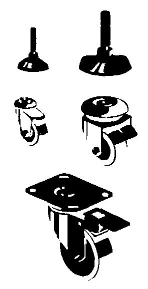
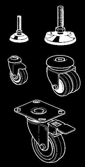
63 components - accessories Adjustables Feet : black polyamide feet with antivibration pad and swivelling bolt. Refer to table underneath for types and dimensions. N 1205 Feet Standard height b Dimensions [mm] A d D D i h Maximum load [N] N 1205 N ± 5 45 ± M 8 M N ± M16 1) N ± N 1211 stainless ± 160 1) To be fitted on a mounting base M20 1) M16 1) Castors Wheels : chrome plated mounting supports, grey rubber tyre. (N 1280/1/2 : polypropylene wheel, for heavy loads) Refer to table underneath for types and dimensions. Castor N 1255 N 1270 N 1271 N 1274 N 1275 N 1278 N 1279 N 1280 N 1281 N 1282 A B B d bolt M8 10,5 10,5 10,2 10,2 8,5 8,5 9 9 D non swivelling version of N 1280 L r Lock no no yes no yes no yes no yes no Maximum load [N] N 1211 stainless steel M8 M8 M10 M M8 SC 4 M16 M16 M8 (M10) N 1274 N 1275 N 1280 N 1281 N 1282 M8 5 6 N 1154 Mounting Bases : To mount feet and castor wheels with M8 to M20 bolt. (other threads on request), with 2 (4) M8 x 20 bolts. Material : plain anodised aluminium. Dimensions Thread M8 M10 M16 M20 N x x 90 N 1151 N 1152 N 1162 N 1154 N 1164 N 1155 N
64 components - accessories N 1250 Anchor Angle - N 1250 : with 2 M8 x 16 screws, 2 washers and 2 M8 SC nuts : used to anchor the uprights of structures on the floor. Material : Pressed steel, black epoxy finish. N 1221 N 1222 M8 Adjustable Foot ± N 1221 M10 Adjustable Foot ± N 1222 Material : Anodised aluminium, foot black polyamide, bolt galvanised steel. N 1225 adjustable adjustable Anchor Foot 45 x 45 - N 1225 : with 6 screws M8 x 20, washers and M8 SC nuts. For adjustable feet made of NORCAN 45 x 45, 45 x 90 and 45 x 180 profiles. For the last two profiles, two anchor feet may be used. 32 ±20 Anchor Foot 45 x 90 - N 1226 : with 6 screws M8 x 20, washers and M8 SC nuts. For adjustable feet made of NORCAN 45 x 90, 90 x 90 and 90 x 180 profiles. For the last two profiles, two anchor feet may be used. Advantage : Easily adjustable for height and perpendicularity. Material : black epoxy coated steel. adjustable 4 adjustable 4 N x x 90 2 x N x N
65 components - accessories x z 3 y adjustable Ø9x adjustable Anchor foot 45 x 45 half closed - N1227: with 2 M8 x 20 screws, 2 washers and 2 M8SC nuts. Used to anchor uprights made of half closed profiles to the floor. Advantage : easily adjustable for height and perpendicularity. 165 Ø11,6 Ø9x N 0670 Masking strip anodised - N 0670 : to seal the profile slots. Ideal for fixing and covering cables in the profile slots. Material : anodised aluminium. Length : 3 m For cutting this profile we recommend using the scissors N 5713 on page 69. N 0712 Masking strip - N 0712 in black PVC, available 3 m length, N 0721 in blue PVC, available 3 m length, N 0724 in grey PP, available 3 m length. Masking strip - N 0713 in black rubber to seal the profile slots. Push in. Available in 20 m length Material : black nitrile rubber. N 0713 new: available in black and aluminium coloured ABS! 66 End Plates : end covers for profiles, to be pushed in. Material : black ABS aluminium grey. black grey dimensions black grey dimensions N 1701 N x 31,5 x 2,5 N 1705 N x 45 x 2,5 N 1702 N x 45 x 2,5 N 1706 N x 90 x 2,5 N 1703 N ,5 / 31,5 x 2,5 N 1707 N x 90 x 3,5 N 1795 N ,5 x 45 x 2,5 N 1695 N x 45 x 2,5 triangle N 1704 N ,5 x 45 x 2,5 N 1694 N x 45 x 2,5!/4 round N 1764 N ,5 x 90 x 2,5 Plugs : for holes and countersinks. Material : polyethylene. N ,4 clear N ,4 black N ,5 clear N ,5 black N sticker, self adhesive : for holes other than 7,4 and 13,5.
 Maximum load per foot: 1500 N Hydraulic pump in 10 executions to drive 1 to 10 cylinders. Manual drive: hydraulic pump with crank; 5 mm/revolution.")

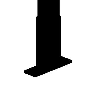
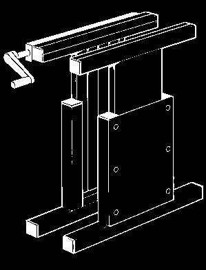
66 components b1 L Telescopic legs for ergonomic workstations : Allows optimal height setting of work surfaces. Technical details : L = 800 ; 1000 ; 1300 ; 1600 mm or without spacer. Height : h = 700 à 1000 mm, (stroke 300 mm) Maximum load per foot: 1500 N Hydraulic pump in 10 executions to drive 1 to 10 cylinders. Manual drive: hydraulic pump with crank; 5 mm/revolution. Pumps for 1 to 10 cylinders. Electric drive : 230 V AC, 160 to 230 W,CE certified. Hydraulic pump with electric drive for 1to 10 cylinders Important : Our telescopic legs are designed for occasional height regulation but not for continuous service. After 1 minute of service under full load allow to cool down for 20 minutes. Cylinder: simple acting hydraulic cylinder made of brass/ stainless steel Stroke 300 mm, speed 400 mm/s maximum. Minimal load to assure the return of the plunger: 60 N/plunger. Other applications for telescopic legs : - ergonomic workstations (P. 82) - mobile workstations - mobile supports for plates, sheet metal etc - angle adjustment b2 manual drive control box for electric drive Above: ergonomic workstation on standard NORCAN telescopic legs. Besides: chariot for the transport of wind tunnel models on 2 height adjustable pairs of rollers. 67
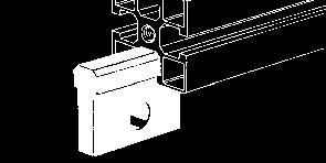
67 components - accessories N 1394 N 0869 N ,5 45 N 0868 N 0867 N 1605 U section profile 31,5 x 45 - N 0868 : To provide a neat solution for routeing cables, air lines, etc. It can be mounted on its supports N 1394 or on snap in cover for U section profile N Material : anodised aluminium. Maximum length 6000 mm. U section profile 45 x 45 - N 0867 : like N0868, the higher moment of inertia and the profile slot allow it to be used as a structural profie. Support 1/ 4 turn for U section profile - N 1394 : For securing a number of cables or air lines. The U section profile N 0868 clips onto this part. Material : PA, black, temperature - 25 C to 140 C. Snap in cover for U section profile - N 0869 : To provide a sealed unit where it is not possible to use a NOR- CAN profile as a support. End cap 31,5 x 45 for U profile N N 1603 : with possibility for cable passage 16 and 2 parker screws. Material: PA % GF. End cap 45 x 45 for U profile N N 1605 : with possibility for cable passage 16 and 2 M5 x 8 screws. Material: PA % GF. Cable grommet Ø16/13 - N 3665 : for end caps N1603 (will not match on N1605!). N 1395 Cable fixing block!/4 turn N 1395 : for securing a number of cables or air lines. Material : Polyamide, black. Temperature : C N 0870 N 1601 N 1611 N 0871 Conduit profile - N 0870 : for electrical installations. Material : plain anodised aluminium. Maximum length 4000 mm. Conduit profile end cap - N 1601 Conduit profile end cap with cable passage - N 1602 Snap in cover - N 0871 : For conduit profile N 0870 Material : plain anodised aluminium. Maximum length 4000 mm. Snap in cover with openings 45 x 45 - N 0872 : For conduit profile N Allows use of Mosaic 45 accessories. Material : plain anodised aluminium. Earth connecting wire - N 1611 : Flexible connecting wire with 2 connections. Use one earth wire for each element N 0870, N 0871, N N 1602 for mosaïc 45 electrical equipment N
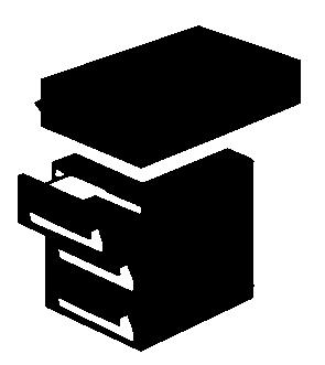
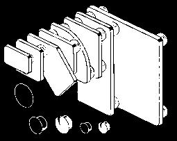
68 components - drawing - tools metal Pneumatic plates : allows to use central core of profile 45 x 90 mm N 0116 (for any other profile contact us) as a duct. Maximum pressure : 7 bar. N 1157 : end plate 12 x 45 x 90 mm with 1/2 tapping N 1158 : end plate 12 x 45 x 90 mm with 3/4 tapping N 1150 : end plate 12 x 45 x 90 mm w/o tapping N 1191 : side connector 12 x 20 x 70 mm with 1/8 tapping N 1192 : side connector 12 x 20 x 70 mm with 1/4 tapping N 1190 : side connector 12 x 20 x 70 mm w/o tapping N 1159 : seal 45 x 90 mm, 0,5 mm thick N 1169 : seal 90 x 90 mm, 0,5 mm thick - for any application contact us! Drawers, enamelled pressed steel : colours : light grey RAL 7035 ; Mounted on silent roller slides. Barrel lock. Ref. N 1550 N 1555 N 1556 N 1558 N 1560 b L h drawers : number (height from top to bottom) T1 1 drawer (100 mm) B2 2 drawer unit (200 ; 200 mm) B3 4 drawer unit ( 50 ; 50 ; 100 ; 200 mm) B5 3 drawer unit ( 100 ; 100 ; 200 mm) TBS1 1 drawer unit (85 mm) wood or melamine Racks in grey melamine Ref. N 1570 N 1573 b L h drawers : number (height) 1 drawer (150 mm) 3 drawer unit (150 ; 150 ; 150 mm) N 1549 Drawer supports - N 1549 with M8 x 16 screw, washer and M8 SC nut. Quick fixing for drawer units into NORCAN structures. Isometric drawing paper - N 5980 : to facilitate the drawing of your project in an isometric perspective. Hatched in 5 x 5 x 5 mm, particularly suited to 1/10 scale, light blue on white background, A3 (297 x 420 mm) format, supplied in 50 sheet blocks on cardboard support. Example see page 70. Set of keys - N 5210 : for low head M8 screws (5 mm). N 5210 N5713 Pair of scissors for strips - N 5713 : for cutting sealing, cover and mounting strips of rubber, PVC and aluminium. 69

69 isometric paper Isometric drawings of NORCAN structures give an excellent impression of the project with easily readable dimensions. The NORCAN isometric paper with its 5 mm grid is ideal for drawing to 1 /10, 1 /20, 1 /50 size. All lengths parallel to the x, y, z axis appear at 1 /10, 1 /20, 1 /50 of their actual length. 70


70 software N_CAD CD rom N_CAD from AutoCAD version 14 and above. Supplied with a 3D library in *.DWG format. It contains : - NORCAN Profiles - Panels - NORCAN Accessories - NORCAN Conveyor Elements N_CAD is a software package which facilitates the design of structures incorporating NORCAN profiles and accessories. It s possible to produce a complete parts list of all the NORCAN elements contained in the design. The software will also calculate weights and prices. Contains also a 3D library in IGES and STEP format. Catalogues Libraries Software N_CAD directly from 71
71 drill jigs, drills, fluteless taps N 5610 (l 7,4) Hinge fixing : Hole dia. 7,4 for M8 with fluteless tap N 5820 N 5810 l 5 Hinge fixing : Hole dia. 5 for M6 with cutting tap N 5820 N 5810 N 5820 Housing profiles Housing profiles N 5810 N 5810 N 5610 ( 7,4 for M8) N 5840 version with 2 jigs N 5860 N 5630 N 5860 N 5840 N 5830 N 5830 Housing profiles N 5830 All slotted profiles N 5630 N 5850 N 5630 N 5860 N 5840 N 5860 N 5840 N Hole finishing for screw in M8 x 43 closed profile N 5800 N 5850 N 5850 All closed profiles All closed profiles Reference d d 1 L 1 N 5610 N 5621 N 5630 N 5640 N 5510 N 5520 N 5610 N 5621 N 5630 N 5640 N 5651 N 5510 N 5520 drill (aluminium type) for tapping with fluteless tap M8 special drill for preparing the tapping with fluteless tap M10 into a 7,4 dia. hole stepped drill for drilling/countersinking for M8 screws stepped drill for drilling/countersinking for hole finishing for M8 x 43 screws into closed profiles stepped drill 8,4 x 20 fluteless tap M8 fluteless tap M10 7,4 7,4 8,4 8,4 8,4 M8 M10-9,2 13,5 13,
72 using M8 screws and bolts 3 M8 by fluteless tap only! F A < 10 kn F A < 10 kn F A < 1kN F A < 10 kn M S < 15 Nm M S < 15 Nm M S < 5Nm M S < 15 Nm 2 M8 by fluteless tap only Supporting thread length > 12 mm F A < 18 kn M S < 20 Nm The figures 2-11 opposite illustrate the main means of fixing M8 screws and nuts to NORCAN profiles. F A is the maximum shear stress of the screw or of the nut along its axis corresponding to the limit of elasticity of the material of the profile. M S is the tightening torque of the bolt or of the nut (a 20 Nm torque is equivalent to a firm tightening with our T key). Fig. 2 : M8 axial tapping with fluteless tap - identical with all NORCAN profiles. Fig. 3 : M8 axial tapping with fluteless tap.tapping in the external side only is for applications with moderate stress. Radial tapping is not possible in the closed side of N 0275 and N 0276 profiles. M8 SC M8 SC Fig. 5 : Standard M8 hex and square nuts (13 mm key) can slide along the slots whilst being prevented from rotating. The M3 to M8 SC, DSC, LSC, RSC, RLSC nuts can be tilted and inserted into the slot. 5 F A < 6kN 2) F A < 6kN 2) M S < 20 Nm M S < 20 Nm Fig. 8 : M8 standard screws (head dia. 13 mm ) can slide along the slot. Hex or square-head screws are restrained from rotating. F A < 6kN (screw head with square washer 1) 2) M S < 20 Nm (screw head with square washer) 8 Fig. 9 : Screws and counterbore holes at the correct depth. Attention! refer to figs 9 & 10 on page 56, for 45 x 90 profiles. The closed sides of the light profiles N 0275 and N 0276 are not designed as a load bearing face. 9 F A < 18 kn F A < 18 kn F A < 6kN 2) M S < 20 Nm M S < 20 Nm M S < 20 Nm 1) Fig. 11 : Holes and countersinks for screws at the correct depth. 1) - Profiles with slots : if using inside the slots fasteners other than a square head without a square washer, M S will be reduce by 25 % and the security factor for F A has to be increased. 11 F A < 18 kn F A < 18 kn F A < 6kN 2) M S < 20 Nm M S < 20 Nm M S < 20 Nm 1) 2) - The value of F A is taken at a distance of 20 mm from the end of the profile. Below 20 mm the value of F A is reduced by 50 %. 73
73 loads and deflections Profiles supported at both ends : in practice these normally fall more or less half way between the deflection of a beam resting on two simple supports, and that of a beam embedded at the both ends. Where c anchorage elasticity (Mean value) Cantilever Profiles : Under a point-load F, the tip of the cantilever beam will show a deflection f which is made up of the deflection f 1 of the profile beam itself, plus the elastic deformation of the beam anchorage f 2. To facilitate the choice between different mounting methods, the most common cases are illustrated below. For the maximum permissible moment (F L) max two values are quoted below - The first has been calculated on the basis of the data given in section Using M8 screws and bolts with a coefficient of friction of 0.1. The second one (between brackets is the result of a series of practical tests (see P 75). Method A31 : NORCAN 45 x 45 mm fixed with 1 central screw M8x20. Heavy profiles F A max = 6000 N F max (for L = 0) = 1800 N (F L) max = 135 Nm (150 Nm) f FL FL 2 Ex. F = 100 N : L = 1000 mm f 5,5 mm Other profiles 1) F A max = 6000 N F max (for L = 0) = 1800 N (F L) max = 135 Nm (150 Nm) f FL FL 2 Ex. F = 100 N : L = 1000 mm f 7,5 mm Method B31 : NORCAN 45 x 45 mm fixed with 1 central screw M8x20. plus 2 corner triangles Heavy profiles F A max = 6000 N F max (for L = 0) = 5400 N (F L) max = 135 Nm (250 Nm) f FL FL 2 Ex. F = 100 N : L = 1000 mm f 4 mm Other profiles 2) F A max = 6000 N F max (for L = 0) = 5400 N (F L) max = 135 Nm (250 Nm) f FL FL 2 Ex. F = 100 N : L = 1000 mm f 4,5 mm Method C01 : NORCAN 45 x 45 mm fixed with 2 corner triangles without central screw Heavy profiles F A max = 3600 N F max (for L = 0) = 3600 N (F L) max = 81 Nm (230 Nm) f FL FL 2 Ex. F = 100 N : L = 1000 mm f 4 mm Other profiles 2) F A max = 3600 N F max (for L = 0) = 3600 N (F L) max = 81 Nm (230 Nm) f FL FL 2 Ex. F = 100 N : L = 1000 mm f 4,5 mm P P Method A21 : NORCAN 45 x 45 mm fixed with 1 central screw M8 x 43 Heavy profiles F A max = N F max (for L = 0) = 1800 N (F L) max = 292 Nm (300 Nm) 3) f FL FL 2 Ex. F = 100 N : L = 1000 mm f 4,5 mm Other profiles 1) F A max = N F max (for L = 0) = 1800 N (F L) max = 292 Nm (300 Nm) 3) f FL FL 2 Ex. F = 100 N : L = 1000 mm f 5,5 mm 74 Method B21 : NORCAN 45 x 45 mm fixed with a central screw M8 x 43 plus two corner triangles Heavy profiles F A max = N F max (for L = 0) = 5400 N (F L) max = 292 Nm (300 Nm) 3) f FL FL 2 Ex. F = 100 N : L = 1000 mm f 4,0 mm Other profiles 2) F A max = N F max (for L = 0) = 5400 N (F L) max = 292 Nm (300 Nm) 3) f FL FL 2 Ex. F = 100 N : L = 1000 mm f 4,5 mm
74 loads and deflections Method A32 : NORCAN 45 x 90 mm fixed with 2 central screws Heavy profiles F A max = N F max (for L = 0) = 3600 N (F L) max = 450 Nm (600 Nm) f 4, FL 3 + 3, FL 2 Ex. F = 100 N : L = 1000 mm f 0,8 mm Other profiles 1) F A max = N F max (for L = 0) = 3600 N (F L) max = 450 Nm (600 Nm) f 5, FL 3 + 6, FL 2 Ex. F = 100 N : L = 1000 mm f 1,2 mm Method B32 : NORCAN 45 x 90 mm fixed with 2 central screws plus 2 corner triangles Heavy profiles F A max = N F max (for L = 0) = 7200 N (F L) max = 450 Nm (900 Nm) f 4, FL *) 10-9 FL 2 Ex. F = 100 N : L = 1000 mm f 0,7 mm Other profiles 1) 2) F A max = N F max (for L = 0) = 7200 N (F L) max = 450 Nm (600 Nm) f 5, FL *) 10-9 FL 2 Ex. F = 100 N : L = 1000 mm f 0,8 mm Method C02 : NORCAN 45 x 90 mm fixed with 2 corner triangles without central screw Heavy profiles F A max = 3600 N F max (for L = 0) = 3600 N (F L) max = 162 Nm (550 Nm) f 4, FL FL 2 Ex. F = 100 N : L = 1000 mm f 0,7 mm Other profiles 1) 2) F A max = 3600 N F max (for L = 0) = 3600 N 2) (F L) max = 162 Nm (550 Nm) f 5, FL FL 2 Ex. F = 100 N : L = 1000 mm f 0,8 mm P Method A22 : NORCAN 45 x 90 mm fixed with 2 central screws M8x43 Heavy profiles F A max = N F max (for L = 0) = 3600 N (F L) max = 731 Nm (800 Nm) 3) f 4, FL FL 2 Ex. F = 100 N : L = 1000 mm f 0,7 mm Other profiles 1) F A max = N F max (for L = 0) = 3600 N (F L) max = 731 Nm (800 Nm) f 5, FL FL 2 Ex. F = 100 N : L = 1000 mm f 1 mm P Method A34 : NORCAN 45 x180 mm fixed with 4 central screws M8 x 20 Heavy profiles F max (for L = 0) = 7200 N (F L) max = 1536 Nm 3) f 0, FL FL 2 Ex. F = 100 N : L = 1000 mm f 0,2 mm Other profiles 1) F max (for L = 0) = 7200 N (F L) max = 1536 Nm 3) f 0, FL FL 2 Ex. F = 100 N : L = 1000 mm f 0,2 mm P Method B22 : NORCAN 45 x 90 mm fixed with 2 central screws M8x43 plus 2 corner triangles Heavy profiles F A max = N F max (for L = 0) = 7200 N (F L) max = 731 Nm (900 Nm) 3) f 4, FL FL 2 Ex. F = 100 N : L = 1000 mm f 0,7 mm Other profiles 2) F A max = N F max (for L = 0) = 7200 N (F L) max = 731 Nm 3) f 5, FL *) 10-9 FL 2 Ex. F = 100 N : L = 1000 mm f 0,8 mm P Method A24 : NORCAN 45 x180 mm fixed with 4 central screws M8 x 43 Heavy profiles F max (for L = 0) = 7200 N (F L) max = 1536 Nm 3) f 0, FL 3 + 0, FL 2 Ex. F = 100 N : L = 1000 mm f 0,1 mm Other profiles 1) F max (for L = 0) = 7200 N (F L) max = 1536 Nm 3) f 0, FL 3 + 0, FL 2 Ex. F = 100 N : L = 1000 mm f 0,1 mm Conditions of test : Profiles: Material NF 6060 T56 ( DIN AI Mg Si 0,5 F 25), shear stress 250 Nmm -2, elastic limit > 200 Nmm -2, anodised 15 µm. Screws and Bolts : All tests carried out with M8 x 20 or 43 low-head socket screws, quality 8.8 zinc coated, threads and bearing face MoS 2 treated, tightened at 20 Nm with torque wrench which is equivalent to a vigorous manual tightening with our Allen key N 5210 and ensures a preload of about 18 kn. For profiles with slots, screw heads were resting on N 3355 square washers for a better load distribution. Nuts used were M8 SC NORCAN nuts. For all tests the point of maximum load (F A and the compression resistance at point P) is taken at a minimum distance of 20 mm from the end of the vertical profile. Below 20 mm the value of the admissible load (F, F A, the compression resistance at point P and the resulting torques F L) and stiffness are reduced until 50 % towards the end of the profile. Limit load F A max ; F max ; (FL) max are the maximum loads before occurrence of the first signs of permanent deformation or sliding. The limit loads F A max ; F max ; (FL) max are not cumulative and correspond to profiles of nominal dimensions. Profile 90 x 90 mm (90 x 180) Virtually equivalent to two parallel 45 x 90 mm (45 x 180) profiles *) Value before the appearance of the first signs of sliding under the corner triangle. 1) Profiles N 0275 and N 0276 : These light profiles can be assembled only onto their slotted faces and their front section. For the mounting methods A31, A21, A32, A22 the elastic limits F A max, F max, (FL) max approach the corresponding values of the other profiles, the deflection f 2, due to the lower of inertia is % higher. 2) Profiles N 0275 and N 0276 : No corner triangles can be mounted on the closed face of these light profiles. 3) The torque FL is limited by the compression resistance of the profile at point P (13 kn) 75
75 assembly applications Type of fault Safety factors currently used in mechanics Permanent deformation (exceeding the limit S = 1,2...2 of elasticity) Static rupture S = Dynamic rupture (Fatigue) S = 1,5...3 Instability (Buckling) S = Safety Factors : The safety factors to be applied usually depend on the type of machine, the accuracy of the calculations and the class of danger in case of catastrophic failure. Some values currently applied are indicated in the table opposite. Should the failure present a possible danger for people, the safety factor to be selected may be much higher. 3 weak 4 x z y Stiffness : As a rule, a structure of given dimensions can be constructed with NORCAN profile in different design formats. The different designs do not provide the same stiffness or load bearing capabilities. Example: a table of 1 m x 1.5 m x 0.75 m, load 3 kn. The first solution (fig. 1) uses a support frame for a plate made up with 45 x 90 NORCAN profiles fixed on legs in 45 x 45 profiles with 1 M8 screw per leg. In case of horizontal thrust in direction x, this connection will be stressed in the least favourable manner with a great deal of flexibility and have a tendency to vibrate. In the second solution (fig. 2 ), the legs of the table are embedded in the plate support frame and fixed with 4 screws each providing a significantly higher stiffness (see also calculations on page 74 and 75). For very high loads we recommend solutions alike fig M8 x 43 x z y Closed profiles : Increase security 6 8 M8 x 43 F Through Bolt : In case of applications under stress, the mounting with the M8 x 43 through-bolt will offer the following benefits : 1. Mechanical resistance (see tables p. 74 to 75) : as the bolt rest, in this solution on the web of the profile, permissible values for the shear force F A and the moment FL are notably increased. 2. Stiffness : The stiffness of the mountings with a through-bolt is virtually double of those with M8 x 20- screws. For the same load, the elastic deformation will be limited to approximately half. 3. Safety : Certain safety requirements demand, that an element whose fixing screw becomes loose must nevertheless remain secured. (fig. 6, 8, 10). Attention! As the screw is stressed in deflection in this application when using slotted profiles, make sure that absolutely accurate calculations of the permissible static and dynamic loads are performed (As a guide : static load will be around 1 kn per screw, dynamic load is of course lower than that). We therefore recommend in this case the use of closed profiles given that if the load slides on the screw the limiting factor will be the shear stress (fig. 6 and 8)


.")
. Fig.")


 or with the adjustable coupling X (fig.")


76 assembly applications 2 Adjustable mountings : Mountings with central bolt allow a limited adjustment only. For longer adjustments, we recommend : - firstly make a mounting with corner triangles and secondly a mounting with a central screw (fig. 1). - to assemble with assembly nuts N 1140 (fig. 2). - to mount with adjustable coupling T - N 1149 (fig. 3). Fig. 4 and 5 show mountings with the adjustable coupling X - N 1148 and the assembly plates N 1110 or N compatible with locking finger N Telescopic mountings : standard 50/46 square tubing can be used for the construction of table legs, cantilevered mountings, and other telescopic or sliding mountings. The fixing is made with two pairs of nuts at 90 (do not position the screws across the axis of the profile - danger of deformation!) (fig. 6). 5 6 Orientable mountings : Assemblies with nuts and bolts allow the construction of orientable structures. With a fixed rotation axis, use a SC nut and a M8 x 43 screw (fig. 8). With a sliding rotational axis the assembly with 2 or 4 corner triangles (fig. 10) or with the adjustable coupling X (fig. 4) will give a possibility of movement in 2 directions. 7 8 Angled mounting (fig. 9) : Profiles cut at an angle of 45 can be assembled directly using a M8 x 20 screw and a M8 SC nut. For all other angles use the angled assembly coupling N Angles of 45 (135 ) on safety housings : The NORCAN profile 31,5/45 - N 0195 enables profiles and panels to be joined at an angle of 135 (fig. 11/12)
77 assembly applications - electrical continuity Cruciform mounting: For the very few cases where a cruciform mounting is necessary, we offer the following solutions : - Assembly nuts N 1140 (fig. 1). - Assembly with a 12 x 45 x 180 plate N 1172 (fig. 2). - Assembly with corner triangles (fig. 3). - Assembly with the 5-directional block N1125 (fig. 4). - For special applications we dispose a certain number of cruciform mountings with central screws almost invisible from the outside. Details on request. - Assembly with adjustable coupling T N 1149 (fig. 5). 1 2 N N Electrical continuity Aluminium profiles, fasteners and metallic accessories are good conductors and the contact surface of screws and unanodised aluminium provides good electrical continuity. The surface layer of anodisation is however, an efficient insulator. Electrical continuity between profiles and fastener is normally achieved through : - tapping into profiles (fig. 6 and 7). - counterboring of the profiles into the profile core (fig. 8) - the head of bolts and nuts with an electrical continuity washer, N 3356, in the profile slot or any anodised face (fig. 10). - all joints using grubscrews and tightened on the bottom of the profile slot (fig. 9 and similar). For other types of assembly where a bolt head or nut is mounted on an anodised face use a serrated washer or an electrical continuity washer N 3356 which enable electrical continuity by piercing the anodisation layer (fig. 10). Please note that hinges only provide weak electrical continuity. An earth connecting wire should be used Important : on request we can supply our aluminium profiles with conductive "ALODINE" finish 10 78
78 doors and windows Doors and windows of moderate size (up to,about 0,2 m 2, not subject to vibration) can be completely fabricated in organic glass or transparent plastic (acrylic Plexi, PVC, polycarbonat, PS, etc., fig 1). For window panes of intermediate size (up to about 0,6 m 2 we recommend a frame in 31,5 x 18 mm NORCAN profiles. (fig. 2 and 4). Doors and window panes exceeding 0,6 m 2 as well as doors under stress or subject to vibration must be framed with 31,5 x 31,5 mm to 45 x 90 mm NORCAN (fig. 5). Tilting housings or hoods should preferably be made in 31,5 x 31,5 NOR- CAN profile whose low weight and absence of apparent slots offer significant benefits in the safety housing field (fig. 3). 1 N N N Folding doors : Foldings doors are easily made using hinge elements. The angle between the two doors must not go below 20 so as to not overload the hinges and pins. (Folding doors supplied ready assembled are fitted with a stop). 6 stop N 1345 Sliding doors and windows : 4 to 5 mm sliding windows in organic glass of moderate size are mounted in N tracks profiles (fig. 7). Windows panes in organic glass as well as sliding doors 8 mm thick are to be mounted : - directly in the slot of the NORCAN profile (fig. 8, 10) - using a N track profile or its N track version (fig. 7). Insertion of 8 N 0517 tubing in the lower slot will allow removal of the pane without dismantling the frame. For smooth and silent sliding we recommend the use of N 1345 pads for sliding doors (fig. 7). 7 N 0414 For clearance free fitting slightly deform the material as shown N 0411 >
79 doors and windows Don t tighten this screwuse adhesive fixing N N Sliding doors and windows framed with NORCAN profiles, whose weight is supported by the upper guide are to be mounted as follows : - in the slot of the upper guide via a N 1360 or N 1356 profile (fig. 1 & 2). - in the rail N 0820 (page 34). - in the slot of the lower guide on a 8 mm strip in polyamide, polyacetal or polyethylene (fig 3 & 4), on the guiding pad on M8 screw N 1348 (page 33) or on the retractable guiding finger N 1480 (fig 9 and 11). - on the double door rail N 0820 (p 46). 4 plastic coated screw 3 N Sliding doors and windows framed with NORCAN profiles, whose weight is supported by the lower guide are to be mounted as follows : - on polyethylene H-shaped guide profile N 1362 (fig 6 & 8). Attention! taking out a sliding door requires disassembling of the upper aluminium rail. For easy removal, we recommend an upper guide made of the guide profile 3 tracks N 0411 and 4 guiding fingers N 1480 which can easily be pulled back after loosening the locking screw (fig. 9). 8 N in the upper guide slot on an 8 mm strip of polyamide, polyacetal or polyethylene (fig 10). - in the lower guide on slot on an 8 mm strip of polyamide, polyacetal or polyethylene which may be supported by bearings for smoother operation (fig. 12). For frames and sliding windows in 31,5 x31,5 mm and 31,5 x 45 mm profiles, N 1315 guiding rollers are mounted in a counterbore. Sliding frames which are easily removable are guided laterally by the polyamide guiding finger N 1480, which can be pulled back after loosening the locking screw (fig 9 & 11) N


80 modular security screen Modular security screen for enclosing security areas. Upright (fig 3) : Height : 2000 and 1600 mm Profile : 45 x 45 mm With mounting foot and 4 screws M8 x 20. Frame (fig 4) : Height: 1800 and 1400 mm Width : 500, 750, 1000, 1500 mm Profile : 18 x 31,5 mm; Panels available : - Beige melamine 8 mm thick - polycarbonat transparent or smoked 5 or 8 mm thick - Aluminium anodised, 2 mm - Wire mesh, welded, 40 x 40, in painted, zinc coated steel or anodised aluminium wire. - Glass laminated 6,3 mm thick 22, ,5 - Other panels on request. Door (fig 5) : Height : 1800 mm Width : 1000 mm Profile : 31,5 x 31,5 mm and 31,5 x 45 mm with hinges, screws and handle N Options : - Ball latch - Door handle N with key. upright - safety switch like SCHMERSAL AZ ZVRK 30 N with brackets Panels of doors like the frames shown above. Important : The doors are delivered without uprights but with the higher door strut. frame frame x (1400) 2000 (1600) (1400) 1955 (1555) 2000 (1600) M8 width frame width 1000 upright width frame door (delivered without uprights) 81
.")
81 workstations Workstations of modular design permitting many different combinations to be realised. Work surface in different material : chipboard, plywood, melamine or for the electronic industry antistatic and the solder resistant. Parts transfer using an integral conveyor (see opposite). We can also install ultra thin conveyors. Framework dependant on the load : standard, heavy, vibration resistant. Feet fixed, adjustable, with castors, telescopic. Conduit for electrical cables. Integrated pressurised air distribution. Lighting including individual spot lights for the working area. Trays, document supports etc. on articulated arms. Shelves adjustable in angle and height Integral draw units. Integral, adjustable foot rests. 82

82 workstations NORCAN rotobox is a new type of ergonomic workstation designed to increase productivity. NORCAN rotobox has a 4 position rotary magazine, it can be re-charged without disturbing the operator. NORCAN rotobox simplifies the management of stock which is key in any ISO9000 system. Access is protected by security switches and the housing gives effective dust protection. Storage capacity : 4 magazines of 5 boxes plus 1 accessory shelf. Dimensions : Width 1,3 m. Depth : 1 m. Height : 1,3 m Power supply : 400/415 V three phase (on request 230/240 V single phase). Additional equipment : belt and roller conveyors, lighting and work surfaces


83 Made to measure workshop and office furniture CARENAL NORCAN furniture, with a clean and functional design, are made of an anodised aluminium structure, with no visible fixing slot, together with a large selection of panels and glass panels. The profile assembly system designed for machine frames, gives this line of furniture a solidity which makes them suitable for both workshop and office. Standard Á made to measure Made to measure by NORCAN is simple ; in the catalogue, each piece of furniture is shown by a photo and a dimensioned 3D design ; you need only make a photocopy and note your specifications and dimensional charges to allow your commercial service to send you a price and CAD 3D drawing. Delivery condition Assembled, packaged or in kit, dependant on size and customer requirements. Machines frames and housings Since the CARENAL furniture range is based on the NORCAN system, the combination of the two ranges assures the aesthetic and technical unity of workshop and office workstations. * these dimensions may be modified 1) measured from worktop surface 84
 with dimensions")


 measured from worktop surface Drawer unit Drawer Workshop")
.")

84 workbenches - offices tables These tables of high aesthetic and mechanical quality are suitable for use in workshop and office and are available in several versions : Standard table(s) with dimensions as shown opposite with 4 legs with 15 mm adjustment, 19 mm recessed worktop in chipboard finished in beige melamine, without drawers or extensions. Extension * Made to measure tables : modify the dimensions marked * on a photocopy of this page. Extension : width and type of workshop same as table worktop. Structure according to load : standard - heavy - vibration. * these dimensions may be modified 1) measured from worktop surface Drawer unit Drawer Workshop suitable for required application. 3 metal drawer unit as shown opposite (Special build : wood, made to measure etc... on request). Specify if drawer unit is to be fitted on left or right hand side of the table. Metallic drawer as shown opposite. Worktop range (identical for all CARENAL furniture) Office (Standard worktop) Standard : Recessed worktop : 19 mm chipboard, smooth beige melamine Heat glued edges Workshop Recessed worktop : 18 mm plywood Polyurethane varnish Electronic Special électronic : Conductive sheet, resistant to hot solder 85


85 office and workshop trolley * these dimensions may be modified 1) measured from worktop surface * Trolley with shelves which may be adjusted in height, depth and angle for office and workshop use : - for printers and tracers - for measurement and inspection equipment - with angled shelves : to hold parts boxes. Standard version as shown opposite with 3 edged shelves in 8 mm chipboard, finished beige melamine, mounted on castor wheels. Made to measure version : note specifications and dimensional modifications on a photocopy of this page. Attention! Specify the number of shelves together with the dimensions of each one. drawer unit * High aesthetic and mechanical quality drawer unit in several versions for both workshop and office. Standard version as shown opposite with recessed 19 mm chipboard worktop, finished in beige melamine, and metallic 3-drawer unit. Made to measure version : note specifications and dimensional modifications on a photocopy of this page. Any vertical panels will be in 8 mm beige melamine chipboard. Drawer unit in other size or to measure in wood / chipboard On 4 rotating castor wheels, 2 braked. 86 * dimensions may be modified (made to measure) 1) measured from worktop surface.
 * dimensions may be modified (made to measure) * High aesthetic and mechanical quality small table available in several versions : Standard version as shown")


.")

86 auxiliary table (secretarial, instruments...) * dimensions may be modified (made to measure) * High aesthetic and mechanical quality small table available in several versions : Standard version as shown opposite with recessed top in 19 mm chipboard finished in beige melamine. Made to measure version : note specifications and dimensional modifications on a photocopy of this page. Structure according to load : light - heavy - vibration Special legs with 400 mm adjustment small unit to support photocopier or other equipment This unit makes functional use of the area actually occupied by your photocopier, fax, laser printer etc... * dimensions may be modified (made to measure) * Standard version as shown opposite with recessed surfaces in beige melamine finished chipboard 19 mm. Vertical panels in same material, 8 mm thick. Made to measure version : note specifications and dimensional modifications on a photocopy of this page. Worktop in 8 mm polycarbonat (specimen on the photo). movable adjustable partition walls for office and workshop * To protect from projections of liquids, chips etc... and to partition off e.g. metrology or mobile inspection areas. Standard version as shown opposite with lower panels in 8 mm chipboard, finished beige melamine, and glass panels in 5 mm polycarbonat. Made to measure version : note specifications and dimensional modifications on a photocopy of this page. for panels and glass panels, see below. Panels in 8 mm chipboard, finished in beige melamine Panels in 8 mm hard PVC on PVC foam centre, blue. Water and oil resistant. Glass in 6 mm mineral multilayer glass "TRIPLEX " type. * dimensions may be modified (made to measure) 87


 Geared motors: 230/400V three")


87 conveyors: catalogue conveyors on request Ø 20 Ø 20 f 50 Ø 20 ø 20 mini belt conveyors : small, but good load capacity. Width: mm and larger. Length to suit. Geared motors: 400 V, 230 V three phase, 230 V single phase with speed controller and 24 V DC brushless minimotors. All our belt conveyors have the NORCAN safety system Ø 50 Ø 50 Ø 50 Ø 50 ø 50 standard belt conveyors : with practically all types of belts: PVC, PU, silicone, felt type for sharp edged pieces. Width: mm and larger. Length to suit. Geared motors: 400 V, 230 V three phase, 230 V single phase with speed controller and 24 V DC brushless minimotors. Ø 50 Ø 50 l 95 ø 95 heavy belt conveyors : for heavy loads. Width mm (up to 2000mm on request!) Length to suit. Geared motors: 230/400V three phased Mesh belt conveyors : ideal for wet and oily pieces (dripping and drying) and accumulation. Width: 100mm upwards. Geared motors 230/400V. Roller conveyors : for parcels, containers and panels. 88

88 application examples Frames and workstation : The two examples on the top of the page show safety housings incorporated into the machine frame. 89

89 application examples Precision frame : This frame was part of an assembly to finely adjust very heavy components. The design in large section profiles and the incorporation of aluminium plates in the structure gave this assembly exceptional rigidity. Automatic packaging line with frame made of half-closed profiles and NORCAN conveyors. NORCAN conveyor with central drive and adjustable frame made of 1/ 2 closed profiles. Automatic station : This unit is an integrated part of an automatic electric component assembly line. The internal frame, actuated via a small air cylinder, slides on standard strips along the grooves in the external frame as detailed on page


90 application examples Large machine frame : The judicious use of closed and half closed profiles resulted in a structure of high torsional rigidity allowing shipment of the fully assembled structure. Feeding of a centerless polisher : Here, the use of slotted profiles has allowed us to easily make a number of settings and adjustments simply by interposing a guide strip N 1350 in opposed slots of two adjacent profiles (see diagram below). 91


91 92 11 m long and 5 m high structure supporting a total load of 3,8 tons on the linear guides of the upper horizontal profiles.
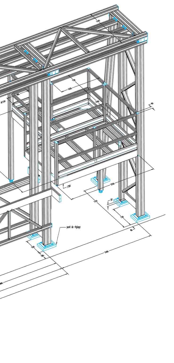
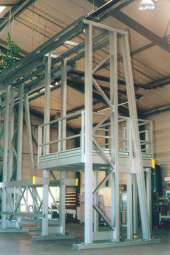
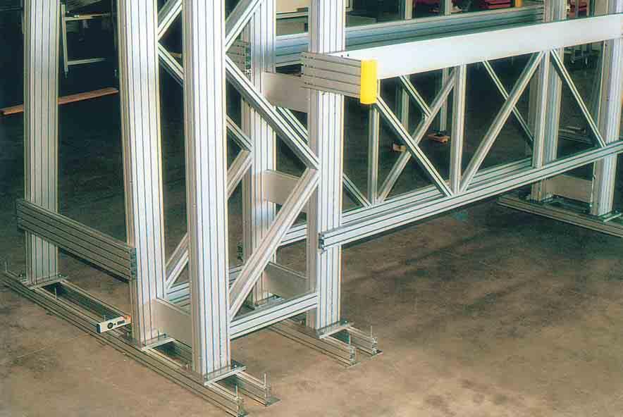
92 large structures

93 application examples Production unit for dental mirrors Rigid framework for vibratory bowl feeder. 94

94 application examples Moveable work station : with hydraulic level adjustment and horizontal table on smooth guides and NAP 57 with lock. Frame vertically mounted with a carriage running on guide blocks and driven by a trapezoidal screw and bevel gear box. Moveable work station : The use of counterweights allows the operator to adjust the height level manually with minimal effort. 95


95 modular frame Modular frame with hydraulic level adjustment for the transport and machining of large panels and metal sheets. 96
 and vertical axis on synthetic guides sliding directly in the slots of the profiles.")
96 special linear modules Linear module with horizontal axis on linear guide type LF... (p 43) and vertical axis on synthetic guides sliding directly in the slots of the profiles. Trapezoidal screw drive with bevel gear.
97 very large guard systems Guards with very long sliding doors : Top: sliding door 2300 mm high and 4200 mm long supported and guided by the upper framework of the structure. Bottom: telescopic sliding door in three parts supported by rollers on the ground. The linear motion is achieved by an integral linear guidance system. Advantage: free access without upper or lower structures in the way. 98
98 99

99 application examples Semi-automatic assembly, inspection and packaging station, with NORCAN frame, housing and conveyor. Work station for assembling and the computerised inspection of precision guide rails. 100

.")


100 application examples Above: safety housings using polycarbonat panels (above left) or mesh panels (above right). Maintenance and repair shop equipped with NORCAN made to measure work stations. The use of closed and half-closed profiles resulted in structure without visible slots. 101


101 production lines Design and construction of the structure of an entire production line complete with its conveyors gravity conveyor rollers gravity conveyor rails belt conveyors 102

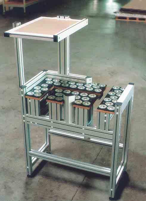
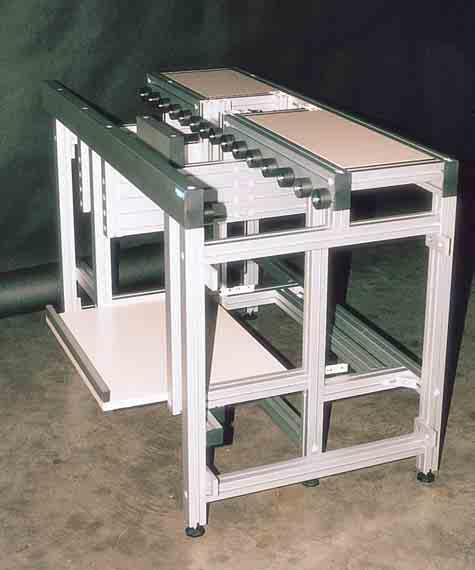
102 ball tables 103

103 104 life storage for work stations
 in several versions: - horizontal storage (manual feeding) - gravity storage (feeding by gravity via sloped rails) - automatic storage")
104 Live storage for workstations made from conveyor rails N0867, N0868 and guide rails N0804 (p.62/63) in several versions: - horizontal storage (manual feeding) - gravity storage (feeding by gravity via sloped rails) - automatic storage (feeding with belt conveyors, roller conveyors etc.) 105

105 application examples 106 Machine frame with integrated guards, conveyors and an axis xy for very high accelerations.


106 Conveyor line for the drying of ceramic pieces with work station and a pivoting conveyor for the passage of a fork lift truck. 107


107 Glove box, vertically sliding on roller guides with counterweights. In accordance with the clean room specifications, there are no profile slots on the outside of the structure. Other clean room applications : - Belt conveyors to clean room specification - Workstation, frames and safety housings made of closed profiles with panels of stainless steel, antistatic compound material etc.

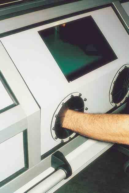
108 clean rooms 109

109 application examples Workstations built with housing profiles and semi-closed profiles. 110

110 application examples Above : Two axis linear unit for manual NAP 57 linear guides and N 1301 roller wheels with wing nut stop system. Opposite : gantry with vertical axis on smooth linear guide and locking handle. The horizontal axis runs on a NAP 57 linear guidance system. Above : small two axis system supported on linear guide blocks with trapezoidal screw drive. Opposite : automatic transfer system comprising 4 belt conveyors and one roller conveyor with driven rollers. 111
Profile series I-40. System kit Profile series I-40
 Profile series I-40 System kit Profile series I-40 n n n a n n n R n a R 45 Profile series I-40 Contents 1 Technical data/profile machining F f Page 1 2 Page 1 3 Page 1 5 Page 1 8 Profiles Page 2 2 3000
Dynamic Elements Linear Slides Mechanical Drive Elements Accessories for Mechanical Drive Elements
 8 Dynamic Elements Mechanical Drive Elements Accessories for Mechanical Drive Elements The Dynamic Elements product group of the MB Building Kit System contains components which enable precise linear movement.
Conveyors 12. slide strips roller Conveyors roller elements Conveyor rollers Chain Transfer
 Conveyors slide strips roller Conveyors roller elements Conveyor rollers Chain Transfer Application example conveyors Transport solutions and goods provision 1 2 3 4 5 6 7 8 362 9 1 slide strips Low-wear
Cross Tensioners. Frames. Bearings. Springs. Mounting Holes. Adjustment Marks
 Cross Tensioners Cross Tensioners provide constant belt or chain tension. Their automatic tensioning action translates into improved performance and extended life for most types of fixed-centre drives.
Indexing Plunger 417. Triangular Knobs, Made from Plastic. Triangular Knobs, Made from Stainless Steel
 Standard Parts for Operating - Overview Cam-Action Indexing Plungers / Indexing Plungers Cam-Action Indexing Plunger 612, Made from Steel and Stainless Steel Page 532 Page 533 Indexing Plunger 417 Indexing
English 1/2015. The Profi le System
 English 1/2015 The Profi le System MayTec System Technology The key to success! Solutions with Innovative Profi le The Profi le System Curved Profi les The Clean-Room System The Telescopic System The Linear
Compact Modules. with ball screw drive and toothed belt drive R310EN 2602 ( ) The Drive & Control Company
 The Drive & Control Company") with ball screw drive and toothed belt drive R310EN 2602 (2007.02) The Drive & Control Company Bosch Rexroth AG Linear Motion and Assembly Technologies Ball Rail Systems Roller Rail Systems Linear Bushings
with ball screw drive and toothed belt drive R310EN 2602 (2007.02) The Drive & Control Company Bosch Rexroth AG Linear Motion and Assembly Technologies Ball Rail Systems Roller Rail Systems Linear Bushings
CLASSIFICATION OF ROLLING-ELEMENT BEARINGS
 CLASSIFICATION OF ROLLING-ELEMENT BEARINGS Ball bearings can operate at higher speed in comparison to roller bearings because they have lower friction. In particular, the balls have less viscous resistance
ABOUT KJN ALUMINIUM PROFILES
 P R O D U C T C ATA L O G U E ABOUT KJN ALUMINIUM PROFILES Our range of Aluminum Profile is available in a large range of sizes starting with 20 x 20 through to 100 x 200 making it suitable to use in all
Protection And Separating Wall Systems
 1 The protection and separating wall sys tem comprises of a number of different profile families. Standard Profiles ( mm thru 8 mm) From the extensive range of Silverline profiles, most static requirements
MECHANICS. Aluminium profiles Linear guides Drive elements Linear units Rotational units
 Aluminium profiles...2-2 Linear guides...2-18 Drive elements...2-44 Linear units...2-52 Rotational units...2-94 Aluminium profiles Aluminium profiles PP profiles Panel profiles PP PP 100 PP 1 PP 200 Overview
Section 5 Doors and Door Components
 0 Section Whether you re looking for plain doors, locking doors, sliding doors, or large walk-through doors, you ll find what you need on the following pages. Bosch offers two basic types of doors that
Bearing retention and clearances
 Bearing retention and clearances Bearing retention 9 Radial retention 9 Axial retention 91 Positioning of single bearing assemblies 91 Positioning of two bearing assemblies 92 Axial retention processes
Profile rail guides LLT
 Profile rail guides LLT Contents The SKF brand now stands for more than ever before, and means more to you as a valued customer. While SKF maintains its leadership as the hallmark of quality bearings throughout
SIT-LOCK self locking elements
 self locking elements Advantages of on the shaft-hub connection compared with traditional systems Easy assembly and disassembly Both actions take place by locking and unlocking the clamping screws with
carriages to carry the load (taking into account any moment loads). Unlike the N series sliders these CS sliders do not have protective side seals.
. Unlike the N series sliders these CS sliders do not have protective side seals.") Light Duty Sliders, size 18 no side seal, front fixing Long Linear s L1918.CS Material Zinc plated steel body. Steel rollers (100Cr6) with metal (2Z) or rubber (2RS) seals. Technical notes To be used with
Light Duty Sliders, size 18 no side seal, front fixing Long Linear s L1918.CS Material Zinc plated steel body. Steel rollers (100Cr6) with metal (2Z) or rubber (2RS) seals. Technical notes To be used with
Linear Drive with Ball Screw Drive Series OSP-E..SB
 Linear Drive with Ball Screw Drive Series OSP-E..SB Contents Description Data Sheet No. Page Overview 1.30.001E 47-50 Technical Data 1.30.002E-1 to 5 51-55 Dimensions 1.30.002E-6, -7 56-57 Order instructions
Shaft Couplings Flange-Couplings Rigid Shaft Couplings Flexible Couplings
 Shaft Couplings Flange-Couplings Rigid Shaft Couplings Flexible Couplings 44 Edition 2013/2014 RINGSPANN Registered Trademark of RINGSPANN GmbH, Bad Homburg 2 Table of Contents Flange-Couplings Page Flange-Couplings
Cylindrical roller bearings
 Cylindrical roller bearings Cylindrical roller bearings are manufactured in a various range of constructive types and sizes, particularly single row cylindrical roller bearings but also two or more row
L Standard Parts for Mould Making
 A Die Sets B Precision Ground Plates and Flat Bars C Lifting and Clamping Devices Shanks, Lifter Studs and Lifting Hooks, Eyebolts Clamping Claws, Screws and Bolts D Guide Elements E Ground Precision Components
Precision Modules PSK
 Precision Modules PSK The Drive & Control Company Rexroth Linear Motion Technology Ball Rail Systems Roller Rail Systems Standard Ball Rail Systems Super Ball Rail Systems Ball Rail Systems with Aluminum
Alcoa Fastening Systems. Camloc Quick-Operating Fasteners
 Camloc Quick-Operating Fasteners Contents Page General Information... A-2 Important Information... A-3 - A-4 General Installation Instructions for 1/4-Turn Fasteners... A-5 1/4-Turn Fasteners 5F Series...
Stirrup-shaped handles, machine handles, apparatus handles
 Stirrup-shaped handles, machine handles, apparatus handles 231 K0186 Stirrup-shaped handles GJS 400 Deburred and tumble cleaned; black plastic coated; machined contact faces. KIPP Stirrup-shaped handles
SNR, YOUR GUIDE TO LINEAR MODULES
 SNR, YOUR GUIDE TO LINEAR MODULES A bearing manufacturer known across the world For almost a century NTN-SNR has been focusing on the development, design and manufacture of bearings. Today NTN-SNR has
DryLin W Guiding system
 DryLin W Guiding system Introduction Your choice of length and width DryLin W is a low cost linear guiding system that was developed to provide both design flexibility and quick assembly in both single
Linear Actuator with Ball Screw Series OSP-E..S. Contents Description Overview Technical Data Dimensions 89
 Linear Actuator with Ball Screw Series OSP-E..S Contents Description Page Overview 79-82 Technical Data 83-88 Dimensions 89 79 The System Concept ELECTRIC LINEAR ACTUATOR FOR HIGH ACCURACY APPLICATIONS
Roller chain idler sprocket units Idler pulley units
 Roller chain idler sprocket units Idler pulley units Roller chain idler sprocket units, idler pulley units Page Product overview Roller chain idler sprocket units, idler pulley units... 334 Design and
Selection Tool. on the Internet at in the section MÄDLER -Tools. Other sizes and designs on request. Connecting Shafts Page 766
 Couplings Overview Friction Clutches Friction Clutches Type B Axial Arrangement Friction Clutches Type C Transversal Flexibility Sliding Hubs with Torsionally-Flexible Coupling Multi-Disk Friction Clutches
Bearings. Rolling-contact Bearings
 Bearings A bearing is a mechanical element that limits relative motion to only the desired motion and at the same time it reduces the frictional resistance to the desired motion. Depending on the design
B Precision Ground Plates and Flat Bars. E Ground Precision Components. G Elastomer-Bars, -Sheets, -Sections
 A Die Sets B Precision Ground Plates and Flat Bars C Lifting and Clamping Devices Shanks, Lifter Studs and Lifting Hooks, Eyebolts Clamping Claws, Screws and Bolts D Guide Elements E Ground Precision Components
From a modest beginning in 1976 producing small. quantities of gravity conveyor rollers, Arnott Handling
 ARNOTT HANDLING LTD From a modest beginning in 1976 producing small quantities of gravity conveyor rollers, Arnott Handling Equipment Limited has grown to become one of the United Kingdom s foremost manufacturers
ROLL-UP COVERS Standard products
 A ROLL-UP COVERS Standard products P.E.I. Roll-up Covers are normally equipped with our patented system of multiple springs. This offers countless advantages: Reliability Compact size Extremely high speeds
Linear Drive with Toothed Belt and Integrated Guide with Recirculating Ball Bearing Guide with Roller Guide Series OSP-E..BHD
 Linear Drive with and Integrated Guide with Recirculating Ball Bearing Guide with Roller Guide Contents Description Page Overview 11-14 Version with Recirculating Ball Bearing Guide Technical Data 15-17
Linear Actuator with Ball Screw Series OSP-E..S. Contents Description Overview Technical Data Dimensions 79
 Linear Actuator with Ball Screw Series OSP-E..S Contents Description Page Overview 71-74 Technical Data 75-78 Dimensions 79 71 The System Concept ELECTRIC LINEAR ACTUATOR FOR HIGH ACCURACY APPLICATIONS
Precision Modules PSK
 Precision Modules PSK 2 Bosch Rexroth AG Precision Modules PSK R999000500 (2015-12) Identification system for short product names Short product name Example:: P S K - 050 - N N - 1 System = Precision Module
Axial-radial cylindrical roller bearings
 Axial-radial cylindrical roller bearings Designs and variants.............. 320 Bearing data..................... 321 (Boundary dimensions, tolerances) Product table 5.1 Axial-radial cylindrical roller
Heavy-Duty Rod Ends - Male with integral spherical plain bearing
 Heavy-Duty Rod Ends - Male with integral spherical plain bearing 65700 Order No. Thread (hand) d 1 l 1 d 2 d 3 d 4 l 2 l 3 X g H7 65700.W0005 Right 5 33 M 5 11,11 18 20 9 14 65700.W0006 Right 6 36 M 6
Glass & Wooden Door Fittings
 Glass & Wooden Door Fittings Product range: Door Sliders Door Track Plastic Glass Clamps Glass Door Channel Aluminium Glass Door Channel Plastic Glass Door Hinges Glass Door Locks Glass Sliding Door Systems
Contents. Page. 1. Product description. 2. The AXC line of linear axes. 3. AXLT line of linear tables. AXC and AXS product overview...
 SNR Industry Contents Page 3 1. Product description AXC and AXS product overview... 6-8 Dynamic load ratings of the linear motion systems... 9 Compact modules... 10-11 Linear tables... 12 Telescopic axes...
FUNCTION OF A BEARING
 Bearing FUNCTION OF A BEARING The main function of a rotating shaft is to transmit power from one end of the line to the other. It needs a good support to ensure stability and frictionless rotation. The
LINEAR RAIL BALL CHAIN TYPE
 LINEAR RAIL BALL CAIN TYPE Svanemærket tryksag 54-73 INDEX Index Product overview... 4-5 Dimension table RC/ERC... 6-7 Dimension table RC... 8-9 Dimension table ARC... 0-3 Dimension table & Grease... 4
FlexLink conveyor Series Y
 FlexLink conveyor Series Y 3 Introduction New conveyor with focus on hygiene The new FlexLink hygiene conveyor was designed to meet the following requirements of special interest to the dairy, food, and
Product overview. 10 Bosch Rexroth Corporation Compact Modules R310A 2602 ( ) Compact Modules CKK. Compact Modules with ball screw drive (CKK)
 Compact Modules CKK. Compact Modules with ball screw drive (CKK)") 10 Bosch Rexroth Corporation R310A 2602 (2008.09) CKK with ball screw drive (CKK) Product overview are precision, ready-to-install linear motion systems characterized by their high performance and compact
10 Bosch Rexroth Corporation R310A 2602 (2008.09) CKK with ball screw drive (CKK) Product overview are precision, ready-to-install linear motion systems characterized by their high performance and compact
Aluminium Productive Fence System 40 PRODUCT CATALOGUE
 11 2017 (e) Aluminium Productive Fence System 40 PRODUCT CATALOGUE solutions by F.EE Elektrotech Engineering Automation Robotik Informatik + Systeme Energietechnik F.EE GmbH In der Seugn 10 and 20 D-92431
Hahn Serie 60 AT. Universal hinge for versatile application. More modern look Improved technology
 Hahn Serie 60 AT Universal hinge for versatile application! More modern look Improved technology 2 4 5 6 7 8 9 2 3 4 5 6 7 8 9 2 Hahn Serie 60 AT For all doors made from metal profile sections NEW! Uniform
ORIGA SYSTEM PLUS Guides, Brakes and Valves for Modular Linear Drive Systems OSP Appendix to the Operating Instructions
 ORIGA SYSTEM PLUS Guides, Brakes and Valves for Modular Linear Drive Systems OSP Appendix to the Operating Instructions TAll personnel who have anything to do with the OSP fitted with guides, brakes or
Doors and fittings. Doors and fittings Aluminum Framing Hinge profile (p. 8-3) Hinge (p. 8-4) Hinge, plastic (p. 8-5)
 Hinge (p. 8-4) Hinge, plastic (p. 8-5)") Doors and fittings Aluminum Framing.0-1 Doors and fittings 1 4 Hinge profile (p. -) Hinge (p. -4) Hinge, plastic (p. -) Hinge, aluminum (p. -) 1 LIFTOFF hinge (p. -) Hinge, removable (p. -) Hinge, adjustable
Doors and fittings Aluminum Framing.0-1 Doors and fittings 1 4 Hinge profile (p. -) Hinge (p. -4) Hinge, plastic (p. -) Hinge, aluminum (p. -) 1 LIFTOFF hinge (p. -) Hinge, removable (p. -) Hinge, adjustable
DryLin R Linear Plain Bearings, Fast and Quiet
 +90º 40º +250º 100º Linear Plain Bearings, Fast and Quiet linear plain bearings, made from solid polymers, are dimensionally equivalent to standard ball bearings. They are made entirely of wear resistant
FLEXIBLE COUPLINGS - RIGID COUPLINGS Up to Nm of torque and 205 mm bores
 Edition 10/2014 www.comintec.it FLEXIBLE COUPLINGS - RIGID COUPLINGS Up to 130.000 Nm of torque and 205 mm bores (BACKLASH FREE) Technology for Safety FLEXIBLE COUPLINGS - RIGID COUPLINGS (BACKLASH FREE):
Easy Slide Rails ov -easy_slide_divider - U pdated
 Easy Slide Rails ov-easy_slide_divider - Updated - 18-09-2017 163 Easy Slide Rails Easy Slide Rails Introduction The Easy Slide family of linear rails have a compact cross-section and low-friction movement.
Guide units. For toolmaking, fixture manufacturing and machine engineering
 Guide units For toolmaking, fixture manufacturing and machine engineering Guide units in compliance with DIN, ISO and STEINEL standards or according to your specifications Guide pillars Guide and pillar
ROSTA MOTORBASES ROSTA. Self-Tensioning Motor Mount for Belt Drives. without slippage self-adjusting maintenance-free
 MOTORBASES Self-Tensioning Motor Mount for Belt Drives without slippage self-adjusting maintenance-free Technology Tensioning Motorbase Type MB for Belt Drives The elastic tensioning motorbase type MB,
Section 10 Conveyors and Transport Components
 1 Section Conveyors and Transport Components Roller elements, roller profiles, support rollers, and other components are perfect to set up lean manufacturing work cells. These non-powered roller elements
12.3 Full Roller Type, MSR Series
 12.3 Full Roller Type, MSR Series A. Construction Carriage End Seal Grease Nipple End Cap Inner Seal Roller Bottom Seal 45 Rail 45 B. Characteristics The full roller type linear guideway, MSR series, equip
Linear Drive with Toothed Belt Series OSP-E..B. Contents Description Overview Technical Data Dimensions Order Instructions 46
 Linear Drive with Toothed Belt Contents Description Page Overview 35-38 Technical Data 39-43 Dimensions 44-45 Order Instructions 46 35 The System Concept ELECTRIC LINEAR DRIVE FOR POINT-TO-POINT APPLICATIONS
Ball splines can be configured for an endless number of automated operations. Demystifying Ball Spline Specs
 Ball splines can be configured for an endless number of automated operations. Demystifying Ball Spline Specs Place a recirculating-ball bushing on a shaft and what do you get? Frictionless movement of
RE / STAR Tolerance Rings STAR Ball Knobs, Knob and Lever Type Handles
 RE 2 970/.99 STAR Tolerance Rings STAR Ball Knobs, Knob and Lever Type Handles STAR Tolerance Rings Product Overview Tolerance rings are made of hard, embossed spring steel strip and belong to the class
...components in motion. Miniature Linear Guideways
 ...components in motion Miniature Linear Introduction Miniature linear guideway systems are widely used throughout industry for precise, compact applications. Precise and Stainless The gothic arch shape
DryLin R Linear Plain Bearings, Fast and Quiet
 +90º 40º +250º 100º Linear Plain Bearings, Fast and Quiet linear plain bearings, made from solid polymers, are dimensionally equivalent to standard ball bearings. They are made entirely of wear resistant
ANTI VIBRATION MOUNTS
 ANTI VIBRATION MOUNTS Insulators The insulators, because of their electrically insulating property, are used for the bearing of blasts, airconditioning units and fans. The fact that they can be anchored
DryLin R Linear Plain Bearings, Fast and Quiet
 +90º 40º +250º 100º Linear Plain Bearings, Fast and Quiet linear plain bearings, made from solid polymers, are dimensionally equivalent to standard ball bearings. They are made entirely of wear resistant
Ball screw drives KGT General technical data
 KGT General technical data Manufacturing process The thread profile is produced by cold rolling in the thread rolling method. Both screw and nut have a gothic thread profile. The load angle is 45. Linear
DryLin R Linear Plain Bearings, Fast and Quiet
 +90º 40º +250º 100º Linear Plain Bearings, Fast and Quiet linear plain bearings, made from solid polymers, are dimensionally equivalent to standard ball bearings. They are made entirely of wear resistant
DS 0002 MOV 2014 DISTITEC Srl
 DS 0002 MOV 2014 DISTITEC Srl The realization of this catalog occurred in tighter control of data contained therein. Due to the ongoing technical evolution of our products, we reserve the right to make
MAIN PRICE LIST. - B 487 Perforated Strip 2 1/2" B 488 Perforated Strip 3 1/2" B 482 Perforated Strip 4 1/2" 9 1.
 PERFORATED STRIPS LENGTH HOLES GBP 1 Perforated Strip 12 1/2" 25 1.63 1 a Perforated Strip 9 1/2" 19 1.51 1 b Perforated Strip 7 1/2" 15 1.39 2 Perforated Strip 5 1/2" 11 0.90 2 a Perforated Strip 4 1/2"
2-9 RG Series High Rigidity Roller Type Linear Guideway
 G99TE17-136 2-9 High Rigidity Roller Type Linear Guideway 2-9-1 Advantages and features The new RG series from Hiwin features a roller as the rolling element instead of steel balls. The roller series offers
The GK units differ from the LK units in that the springs of the GK units have a spring eye at the front.
 01 09 Installation guidelines Mechanical suspension units GK LK GN0032-0 Mechanical suspension units GK LK The GK units differ from the LK units in that the springs of the GK units have a spring eye at
ndustr SNR our guide to linear modules
 ndustr SNR our guide to linear modules SNR A bearing manufacturer known across the world For almost a century SNR has been focusing on the development, design and manufacture of bearings. Today SNR has
Linear Guideways HG Series
 18 G99TE1-67 Linear Guideways 2-1 - Heavy Load Ball Type Linear Guideway HG series linear guideways are designed with load capacity and rigidity higher than other similar products with circular-arc groove
Linear Actuator with Toothed Belt Series OSP-E..B
 Linear Actuator with Toothed Belt Series OSP-E..B Contents Description Data Sheet No. Page Overview 1.20.001E 21-24 Technical Data 1.20.002E-1 to 5 25-29 Dimensions 1.20.002E-6 30 Order Instructions 1.20.002E-7
DESIGN OF MACHINE MEMBERS - I
 R10 Set No: 1 III B.Tech. I Semester Regular and Supplementary Examinations, December - 2013 DESIGN OF MACHINE MEMBERS - I (Mechanical Engineering) Time: 3 Hours Max Marks: 75 Answer any FIVE Questions
Sheet 1 Variable loading
 Sheet 1 Variable loading 1. Estimate S e for the following materials: a. AISI 1020 CD steel. b. AISI 1080 HR steel. c. 2024 T3 aluminum. d. AISI 4340 steel heat-treated to a tensile strength of 1700 MPa.
Precision Modules PSK. The Drive & Control Company
 Precision Modules PSK The Drive & Control Company 2 Bosch Rexroth Coporation Precision Modules PSK R310A 2414 (2008.07) Linear Motion and Assembly Technologies Ball Rail Systems Roller Rail Systems Linear
...our linkages, your solution. Rod Ends
 ...our linkages, your solution Technical Information Introduction All of our rod ends incorporate either a plain spherical bearing, ball bearing, or roller bearing. Below is an overview of each type. Plain
ALUMINIUM PROFILE SYSTEM SERIES 40
 ALUMINIUM PROFILE SYSTEM SERIES With the basic grid mm (slot 5); mm (slot 6), 16mm, mm and 0mm (slot ). In addition to this, the complete connection technology and a large range of accessories. TABLE OF
Features of the LM Guide
 Features of the Functions Required for Linear Guide Surface Large permissible load Highly rigid in all directions High positioning repeatability Running accuracy can be obtained easily High accuracy can
Precision levelling wedges Due to their large contact area Bilz precision levelling wedges (PK) for vibration and structure-borne noise insulation
 for vibration and structure-borne noise insulation") 28 Precision levelling wedges Due to their large contact area Bilz precision levelling wedges () for vibration and structure-borne noise insulation offer optimum support and stiffening of the machine bed.
28 Precision levelling wedges Due to their large contact area Bilz precision levelling wedges () for vibration and structure-borne noise insulation offer optimum support and stiffening of the machine bed.
Mounting Overlap Shield. Face Clamps. Gap. Seat Depth. Lead In Chamfer. Loose Fit.
 Mounting Introduction: Reali-Slim thin section ball bearings have a crosssection thickness that is much thinner than standard bearings of the same diameter, and are therefore more sensitive to shaft and
SAMPLES GAUGES. Tolerances OUR SPECIAL OFFER: PLUG GAUGES WITH REQUIRED FIT OR INDIVIDUAL TOLERANCES ACCORDING TO YOUR SPECIFICATIONS
 SAMPLES GAUGES PLUG GAUGES Tolerances GO side Fit NO GO side OUR SPECIAL OFFER: PLUG GAUGES WITH REQUIRED FIT OR INDIVIDUAL TOLERANCES ACCORDING TO YOUR SPECIFICATIONS BESTSELLER: FEELER GAUGE TAPES IN
Shaft Couplings Tru-Line Flange-Couplings Rigid Shaft Couplings Flexible Couplings
 Shaft Couplings Tru-Line Flange-Couplings Rigid Shaft Couplings Flexible Couplings Edition 2015/2016 RINGSPANN Registered Trademark of RINGSPANN GmbH, Bad Homburg Table of Contents Tru-Line Flange-Couplings
LINEAR ROLLER SYSTEM with MR rail and R, R.T, R.S sliders
 NR R R N NR ROR YTM with MR rail and R, R.T, R. sliders The MR eries inear Rail ystem consists of a -section steel rail with internal convex raceways, where robust double row ball bearing rollers travel.
Bearing preload. Preload considerations
 Bearing preload There may be some applications where the bearing arrangement needs to be preloaded i.e. requires a negative operating clearance. In applications such as machine tool spindles, automotive
10 Thrust ball bearings
 10 Thrust ball bearings Designs and variants.............. 1010 Single direction thrust ball bearings... 1010 Double direction thrust ball bearings.. 1010 Cages............................ 1010 Bearings
Product Description. Characteristic features R310A 2402 ( ) Linear Modules MLR
 Linear Modules MLR") 9 Bosch Rexroth Corporation R310A 40 (1.11) MLR Product Description Characteristic features MLR...: with Cam Roller Guide and Toothed Belt Drive for high-speed applications (up to 10 m/s) with Cam Roller
9 Bosch Rexroth Corporation R310A 40 (1.11) MLR Product Description Characteristic features MLR...: with Cam Roller Guide and Toothed Belt Drive for high-speed applications (up to 10 m/s) with Cam Roller
mechanics LES functional overview LES 4 LES 6 LES 5
 LES functional overview LES 4 with spindle drive Overview 2-54 2-56 LES 6 2-58 with spindle drive LES 5 2-60 with spindle drive Calculations 2-62 Combination examples Motor modules Clutch housing Motor
TABLE OF CONTENTS SERIES 40
 TABLE OF CONTENTS SERIES ALUMINIUM PROFILES SERIES PAGE Technical data and profile cross-sections 2.4-2.17 Processing of profiles for connectors 2.1-2.19 Prices of aluminium profile processing 2. Aluminium
GoTo Europe Focused Delivery Program. Product overview assembly technology
 GoTo Europe Focused Delivery Program Product overview assembly technology 2 GoTo Europe Products you need, delivered when you need them In today s global competition every day counts. Fast response times
R310EN 2211 ( ) The Drive & Control Company
 The Drive & Control Company") eline Ball Rail Systems R310EN 2211 (2006.04) The Drive & Control Company Bosch Rexroth AG Linear Motion and Assembly Technologies Ball Rail Systems Roller Rail Systems Linear Bushings and Shafts Ball
eline Ball Rail Systems R310EN 2211 (2006.04) The Drive & Control Company Bosch Rexroth AG Linear Motion and Assembly Technologies Ball Rail Systems Roller Rail Systems Linear Bushings and Shafts Ball
...components in motion. Easy Rail
 ...components in motion Easy Rail Easy Rail Introduction The Easy Rail family have a compact cross-section and low-friction movement. Robust and Long Service Life Easy Rail s range of cross-sectional rail
Linear Actuator with Toothed Belt and Integrated Roller Guide Series OSP-E..BHD
 inear Actuator with Toothed Belt and Integrated Roller Guide Series OSP-E..BHD Contents Description Data Sheet No. Page Overview 1.15.001E 11-14 Technical Data 1.15.002E-1 to 3 15-17 Dimensions 1.15.002E-4
CKR Compact Modules with Ball Rail Guides and Toothed Belt Drive. The Drive and Control Company
 CKR Compact Modules with Ball Rail Guides and Toothed Belt Drive The Drive and Control Company Bosch Rexroth Corp. Linear Motion and Assembly Technologies CKR RE 8 615 (03.006) Rexroth Linear Motion Technology
In-house development Own manufacturing Sole distributor in Germany Working with distributors worldwide
 In-house development Own manufacturing Sole distributor in Germany Working with distributors worldwide External Clamping devices Overview 3073 Mini-Range For very low torque transmission Very small profile
LONG LENGTH DESIGN MANUAL CONTENTS PAGE. Introduction Long Length features & benefits... 2 Long Length belting programme... 7
 DESIGN MANUAL LONG CONTENTS PAGE LENGTH Introduction Long Length features & benefits... 2 Long Length belting programme... 7 Drive Design Belt drive selection procedure... 8 Belt pitch selection guides...
Crossed Roller Ways. Description of each series and Table of dimensions. Anti-Creep Cage Crossed Roller Way
 Crossed Roller Ways Description of each series and Table of dimensions Crossed Roller Way Page - to -7 Anti-Creep Cage Crossed Roller Way Page - to - Crossed Roller Way Unit Page - to - In the table of
PART BINS CONTAINERS & CONTAINERS. Box Pallets 102. Part Bins & Accessories. Mesh Cages 104. Export Pallets 104. Tote Bins 111. Storage Containers 105
 & PART BINS Box Pallets 102 Mesh Cages 104 Export Pallets 104 Storage Containers 105 Part Bins & Accessories Economy Range Accessories 106 Economy Range 107 Lamson Range 108 Lamson Range Accessories 110
Order from MARYLAND METRICS P.O. Box 261 Owings Mills, MD USA web:
 Push-In Fittings LF 3000 LF 3200: 3 mm LIQUIfit LF 300 LF 300/ LF 3900 LF 0 PARKER LEGRIS Industrial Connector Systems Products are available from: MARYLAND METRICS P.O. Box 21 Owings Mills, MD 21117 USA
Profiles and Mounting options. NEW Additional. HepcoMotion. MCS aluminium frame and machine construction system including MFS fencing system
 NEW Additional Profiles and Mounting options HepcoMotion MCS aluminium frame and machine construction system including MFS fencing system MCS Machine Construction System and MFS Machine Fencing System
Product Datasheet. Cable TV Junction Box (Page 4)
") JUNCTION BOX Product Datasheet Junction Box Bolted Type (Page 2) Cable TV Box (Page ) Cable TV Junction Box (Page 4) Telephone Box (Page 5) Telephone Junction Box (Page 6) GRP Junction Box Enclosures are
JUNCTION BOX Product Datasheet Junction Box Bolted Type (Page 2) Cable TV Box (Page ) Cable TV Junction Box (Page 4) Telephone Box (Page 5) Telephone Junction Box (Page 6) GRP Junction Box Enclosures are
2-1 HG Series - Heavy Load Ball Type Linear Guideway
 2 G99TE15-114 Linear Guideways 2-1 - Heavy Load Ball Type Linear Guideway HG series linear guideways are designed with load capacity and rigidity higher than other similar products with circular-arc groove
INDUSTRIAL VACUUM SYSTEMS MADE AND MANUFACTURED IN GERMANY RANGE OF ACCESSORIES COMPETENCE CENTRE INDUSTRIAL VACUUMING. Valid from
 INDUSTRIAL VACUUM SYSTEMS MADE AND MANUFACTURED IN GERMANY Valid from 01.01.2019 COMPETENCE CENTRE INDUSTRIAL VACUUMING 2 3 DEAR CUSTOMER, This catalogue provides you with an essential selection of the