THE UNIVERSITY OF ILLINOIS LIBRARY
|
|
|
- Laureen Fleming
- 6 years ago
- Views:
Transcription


1


2 THE UNIVERSITY OF ILLINOIS LIBRARY

3


4 Digitized by the Internet Archive in


5 CONSTRUCTION AND CALIBRATION OF A TWIST DRILL DYNAMOMETER EARL PAGE SHAPLAND THESIS FOR DEGREE OF BACHELOR OF SCIENCE IN MECHANICAL ENGINEERING COLLEGE OF ENGINEERING UNIVERSITY OF ILLINOIS 1913
6


7 \~3 \ t) UNIVERSITY OF ILLINOIS May THIS IS TO CERTIFY THAT THE THESIS PREPARED UNDER MY SUPERVISION BY Earl Page 3haplund ENTITLED Construction and Cal ibration of a Twist Drill Dynamometer IS APPROVED BY ME AS FULFILLING THIS PART OF THE REQUIREMENTS FOR THE DEGREE OF...Bachelor...of...science in..mechanical Engineering Instructor in Charge APPROVED: HEAD OF DEPARTMENT OF._Mep^loal Engineering

8


9 TABLE CF OOMIENES. Introducti on. 1. Description of dynamometer 2. G-uages 3. Method of filling reservoirs. 4. Calibration 5. Construe t ion 6. Manner of conducting tests. 7. Method of calculation. 8. Sample calculations. 9. Discussi ons Photographs of apparatus. Calibration curves. Cards with templets to show method of of obtaining the value of the ordinate Table of Drills Table of Results.
10 UIUC


11 TH CONSTRUCTION AND CALIBRATION Oi 1 A TWIST DRILL DYNAMOMETER With the introduction of high speed twist drills in modern machine shop practice comes the j rohlem of their relative economy with that of the slow speed carbon drill which is 3till used to a very large extent. To obtain data upon which the relative economy of these drills could he compared, T. J.Schance designed and built a twist drill dynamometer for his thesis in As the economy of the drill defends up on the; first cost of the drill, the durability of the drill and the operator's time.this machine was so designed that this data could he obtained. This machine was also designed with the view of obtaining the power necessary to operate different drills, and as this power depends vl} on--; the speed, the feed and the angle of the drill, these may be kept constant and the drills compared in this way. Description of the Dynamometer The dynamometer consists mainly of two oil reservoirs or compression chambers, one for the downward thrust and the other for the torcue. The magnitude of the j ressures of these forces on the oil is transmitted to two recording guages, one for each reservoir. The larger reservoir is located in the main casting of the dynamometer base. It is 11 =g inches in diameter and contains about one gallon of fluid. This reservoir is for the x urpose of recording rhe downward thrust of the drill. Across the top of this reservoir and fastened to the sides, to form an air tight chamber, is a rubber diaphram thru which the pros-

12


13 2 sure is transmitted through the medium of the fluid to the guages. Upon this diaphram rests a disc having a diameter slightly less than that of the inner diameter of the reservoir. Resting on this disc and supporting another disc, on which the test piece is clamped, is a large end thrust hall bearing which allows the upper disc free to rotate in the direction of the rotation of the drill and at the same time transmits the downward thrust to the reservoir of oil below. This ball bearing is of the finest Uerman make and provides rotation with praetieally negligable friction. Projecting from the upper disc is a radial arm which transmits the torque of the drill to a vertical reservoir at the left. This reservoir is constructed similarly to the larger one. It has a diameter of 4 *g inches and a capacity of about one pint of fluid. This reservoir is placed in a vertical position vith a rubber diaphrara across the front. A small cast iron pressure plate of smaller diameter than that of the inner diameter of the reservoir presses u.on the diaphram thus transmitting the pressure to the guage. This reservoir is not a part of the base but is a finished casting bolted to the base of the dynamometer. The dynamometer is made entirely of cast iron excepting the end thrust ball bearings. 'i'he base is unfinished except the upper edge of the large reservoir on which a metal ring is bolted and holds the rubber diaphram in place. The face of the is fastened vertical portion on which the smaller reservoir A is also machined. To hold the test pieces of cast iron in place, upon the upper disc, is bolted a casting whose section has the appearance of an H. The test piece being clamped into the upper portio by means of two set screws.
14


15 .. Guages The guages used on this dynamometer are of Special design and are supplied "by the Bristol Guage Co., of "/aterbury, Conn They are of the flattened elfcptical coil spring type. As the torque is a great deal less than the downward thrust, guages of corresponding range were made. The torque guage has a range of eight, lbs.per sc. in., while the thrust guage ranges from lbs. per sq. in. to 25 lbs. per sq.. in. The drill spindle is connected by means of cords to the guage dials so that movement of the drills causes a corresponding rotation of the dial, giving an autographic record of the downward movement of the drill on the record of the downward movement of the drill on the record card. Mechanically this is accomilished by extending the dial shafts through the back of the guages about three inches and mounting them on small pulleys to receive the cords from the drill swindle The cords are given a few turns about the pulley and weights fastened to the cord ends which cause rotation of the dials when the drill spindle is moving upward. With the drill is moving downward action of the cords on the pulleys is reversed and the dials are rotated in the opposite direction. This mechanism gives a record card with absciseaeproportional to movement of drill. Method of filling reservoir. To obtain the correct pressures the reservoirs must be completely filled with fluid in such a manner that no air may be pocketed in them. This was accomplished by filling the reservoirs very gradually and giving the air time to escape through the outlet. The dynamometer was tipped forward until the guages were in a horizontal plane. Two 1/2 inch pipes were then fitted Fig. 2, to the Openings at 1 and E.^&hese pipes were about four feet long and were used to give head to the fluid that it might press
16


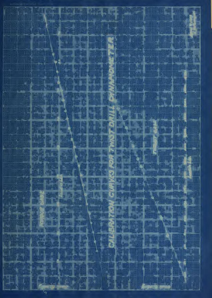
17 4 out the air more readily. The fluid was gradually poured in, giving it time to let the air bubble out. The diaphram was also pressed in at various intervals causing the air to "buhhle out ^uite rabidly. After the reservoirs were filled the dynamometer was left standing in this position for several hours that the air may gain free access to the atmosphere. The valves at 1 and 2 were then closed, the jipes removed and the openings closed. Calibration Before any accurate data could he obtained the dynamometer had to be calibrated and calibration curves drawn. To calibrate the thrust guage, the dynamometer vras placed in a Kiehle testing machine and loads placed uj on the upper disc, over the large reservoir varying from to 2800 lbs. with increments of about 200 lbs. These loads were taken off with larger increments of about 500 lbs. The joints were plotted with the loads as abscissae and the readings as ordinates. These gave a curve very nearly a straight line. In the calibration of the torque guage a more simple method was used. The dynamometer was set u^on the working bench. By means of a knife edged hook, a cord was fastened to the radial arm, then over a pmllsy to a weight holder, heights of five lbs. were placed on the lower end of the cord and their various readings taken and recorded. These increments were placec on up to one hundred ft. lbs. Headings were taken in both ascending and descending increments. A calibration curve,tr as drawn for the torcue with the load as abscdssaeand the readings as ordinates which gave a very good curve especially at the joints where the torque of the drill came.

18


19 Construction To fit the dynamometer iaj that tests might he made several small tasks had to he completed. Cne of the larger ones "being that to fix up a "bracket for the dials. This rack was made of strips of iron two inches wide and three-eight inches thick. They were forged to shape, bolted to the hase and riveted together. The guage was fastened to the "bracket by means of small stoye holts. The largest and more important task completed was that of arranging pulleys in such a manner that the downward motion of the drill would he transmitted to the dials uniformally. This was obtained by fastening a iiece of iron by means of a cap screw a? i p* 1 to the spindle at 2. ^ 5irectly above this. iron and bolted to the drill at 4 was an angular piece of iron in which an indicator pulley was fitted. This iulley was placed in such a positiofi that the traverse of the cord for the various positions of the drill would always be in a vertical line. At the back and above the radial arm a forged bracket 5 was bolted; to this bracket w.eie fitted two indicator i.ulleys. This bracket was placed in such a position that the indicator 1 ulleys would be in a vertical line with the pulleys of the dial at 6 and 7. Fig. 2. The string was first fastened at 3 then up thru the pulley at 4 and then tied to a small ring. To this ring two other cords were fastened, one leading thru the indicator j_ulley Fig. E. at 8 and then down to the pulley at 6 on the tor cue guage The other leading over the pulley at 9 then down to the pulley at 7 on the thrust guage. These strings made three complete turns around the guage pulleys and then fastened to weights 9 and 10
20


21 which hung below. Then as the drill was fed downward the weights were lifted and the friction of the cords turned the pulleys on the guages on which the dials are fastened. Manner of conducting the tests The cards were first placed, in position on the dial with the drill point resting on the test fiece. The power was then 'turned on and the feed clutch thrown in. After the drill had been cutting with its entire edge the Si eed was taken from the drill swindle directly, as the power was transmitted thru several clutches it became necessary that the positive sj.eed he taken from the drill spindle. rhi position of the drill was marked at the beginning and after it had drilled a depth of two inches the drill was removed from the hole and the j.ower shut off. Tests were made of the same drill in cast iron- -varying the feed for each test and keeping the speed nearly \asj constant as possible. Method of Calculation-- As the dials which were furnished with the guages were not calibrated the same as the dynamometer, it ^as necessary to make some arrangement for reading the values of the ordinates of the recorded curve. This was done by means of a templet made of tracing- cloth with the correct calibration of the machine upon it. These templets were divided into seventeen equal parts and altogether representing two inches travel of the drill. These templets were placed over the curves drawn and the values of the ordinates taken and recorded. To obtain the mean value of the ordinate the sum of half of the first plus the sum of the interme diate ones, plus half the last, was divided by the total number of ordinates crossed by the curve. Templets were made both for
22


23 . ' ~ J ) the tor cue and thrust curves. The comparison of the drills was "based u x on the number of foot pounds necessary to drill a one inch hole, two inches deep The total horse power is given "by the horse power of the thrust plus the horse power of the torque. The thrust horse power is given by the lbs. times the distance in feet divided by ft. lbs. The distance traversed is the feed in feet times the R. P. M. of the drill. The horse power of the torque is agair the product of the tor cue in pounds times the distance in feet divided by ft. lbs. To obtain the duty, which is based upon the number of ft. lbs. required to remove one cubic inch of material, multiply the horse power by ft. lbs. and divide by the area of the drill times the feed in inches per minute. Sample Calculations H. P. = Feed (ft. per Mia. ) x Thrust (lbs R.P.M. x torcue x 2 7C p a 1396 x x 258 x 6.28 = 1#041 H.P " ~ H.I. x (33000 Duty =, Area of drill (sq. in.) x feed (inches ± er min) x 33000


24


25 ; 8 Discussion The results obtained were fairly consistent for the same drills keeping the feed and speed cons tant.which goes to show the accuracy and sensitiveness of the apparatus. As the feed was increased and the speed kept constant a larger horse power was required and the duty increased accordingly. With the same feed and varying the speed of the drill the horse power increased with the speed and duty increased also to a lesser degree. For the various drills the horse power and duty varied slightly Tor the same feeds and speeds. Tests of the carbon drill were made only at slow speed hut the horse power required to operate them was about one-half of the high speed drills at twice the speed, showing that the time saved by the use of the high speed drill is off set by the increased horse lower required to operate it. In the test conducted with the helical fluted drills the torque and thrust remained fairly constant after the drill had cut to full size. But in the tests conducted with the straight fluted drill the torque and thrust steadily increased as the drill was fed downward. This increasein torcue and thrust was caused by the chips collecting along the drill and not being carried out as in the helical fluted drill. The one great fault of conducting these tests ^'as the cas iron test pieces. The greater number were full of small blow holes and in some instances blow holes of one inch in diameter were strucl. Yftien the drill struct these blow holes it caused the torque to vibrate over a large range and at the same time increased it materially. The thrust would drop off to a large extent and nothing could be told of its proj.er value. A large number of tests had to be discarded for this reason and in some tests that were taken a -
26


27 1 number contained small bio? holes. Other test iieces contained spots of harder metal which came from melting SOT&p iron with the pig. When attempting to test these pieces the clutches on the dril press would slip and the drill would not operate at a high speed. Summing up all the conditions under which the dynamometer operated it can he said that it showed itself to he sufficiently sensitive and accurate to satisfy the demands of drill tests. If proper test pieces were obtained the dynamometer would give excellent result from which the comparison of drills may be obtained. 9
28


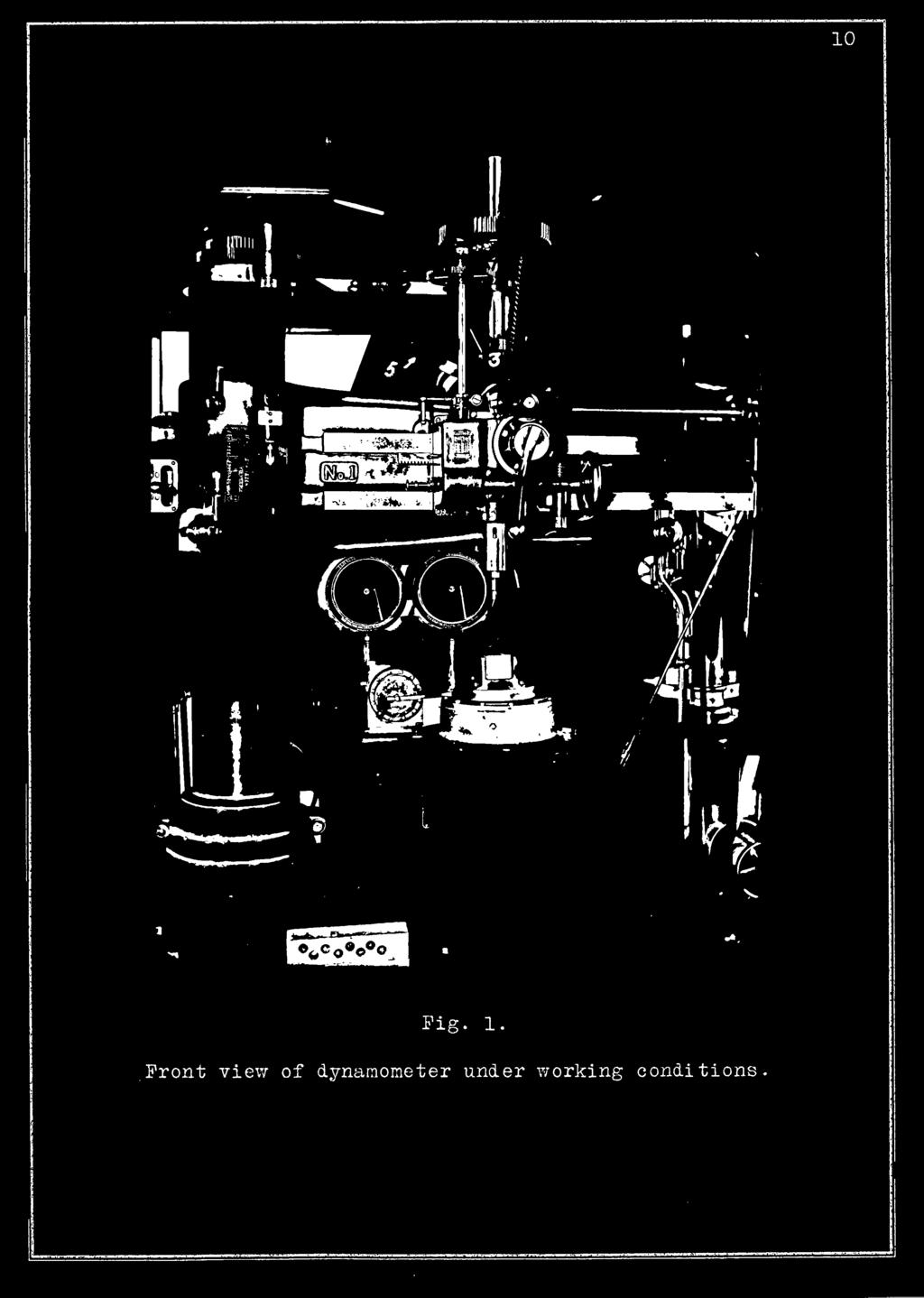
29 Fig. 1..Front view of dynamometer under working conditions

30


31

32


33

34


35 13
36


37 Card with templet in position to obtain the value of ordinates.

38


39 Card with templet in position to obtain the value of ordinates.

40


41
42


43 .. TABLE OF DRILLS Ho. Ivlaker Trade Name Type Clearance Angle 16 Angle of Point 1. New Process T.D.Co. Reliance H. 3. Milled 4 00* 59 30' 2. Detroit T.D.Co. H. 3. Hilled 7 lo' 61 00' 3. Celfor T.D.Co. Type D. U.S. Milled 4 10' 63 30' 4. Celfor T.D.Co. Type B. H. 8. Milled 6O00' 63 00' 5. Whitman and Barnes Co. "Ilorka" Flat Twisted 4 55' f 6. Pratt and 7/hitney Flat Twisted 4 50' 59 30' 7. Union T.D.Co. H. 3. Milled 4 55' 60 00' 8. Lincoln Williams "Pioneer" T. D. Co. H. 3. Flat twisted 6010' 9. Lincoln Williams T. D. Co. H. 3.Milled
44


45 57 6 Drill Test Feed in. per rev. RE SULT3 01 TESTS. R.I.1.1. Torque Thrust Feed in. per min. E.I. 17 Duty T X Q J. 007 UVJ PA4 ft I 7. J. O 01 X <J VJ "I J. A 01 1X kj 36VJ 6.^ T X 1xx1 0"! P J 3Au 14 * x 1 ^ 01 ^ 203 ^ \J i_/ _u W \J A Ol ^ J. VJ X«v p 1 ft. AT UXw ^ tl> U ft - fi _L» W t_/ X p 1x Qv 01 O O <J PO 01 P O b PI 01 ft «J VJ VJ P > _L,. t o?7 007 w c> W \JX\J PI X, / p; V <w P «j A 01 ^. VJ X«J X. 6\J p. P A fil ^ PR 01 2'7 ft QO 01 VJ X VJ o Q. 01 VJ X«J ^ X. v v O QO * 01 VJXVJ ft 24ft 15.2 xu w Q V ^A 007 vjvj / 24ft Q 3 «j ^7 01 i VJ XVJ 24ft Q Q 1/ ^ft 01 ^ X.. 51-L QIJ.VJ 1 p J- -X. J pm Shop Shop


46
47


48
VAN GUNDY & FICK. ELgcirical Lngmeermg. Raisers' ^l:t.s-s ilegd&lw: D. p. DNIV.OV ' OIL 1*;. ;,,; I; 'i. / v- ''UK ','.!'
 I ' i ' I; 'i VAN GUNDY & FICK ','.!' if / v- ''UK Raisers' ^l:t.s-s ilegd&lw: ELgcirical Lngmeermg P C D. p. 1912 1*;. ;,,; DNIV.OV - I CAJJtiTO MS a V.UUf./UVV". "I*. ' OIL THE UNIVERSITY OF ILLINOIS
ENGINE & WORKING PRINCIPLES
 ENGINE & WORKING PRINCIPLES A heat engine is a machine, which converts heat energy into mechanical energy. The combustion of fuel such as coal, petrol, diesel generates heat. This heat is supplied to a
D TO A REAR WHEEL DYNAMOMETER
 ImizisifJiHtmim NATION OF HORSE POWER METER D TO A REAR WHEEL DYNAMOMETER FOR TESTING BY J, V. MILLER G. N, SIEBENALER AUTOMOBILES ARMOUR INSTITUTE OF TECHNOLOGY 1 9 1 6 625.6 Illinois Institute of Technology
Heat Engines Lab 12 SAFETY
 HB 1-05-09 Heat Engines 1 Lab 12 1 i Heat Engines Lab 12 Equipment SWS, 600 ml pyrex beaker with handle for ice water, 350 ml pyrex beaker with handle for boiling water, 11x14x3 in tray, pressure sensor,
For the Shop that Demands the Finest I
 For the Shop that Demands the Finest I R VARIABLE SPEED DRIVE 3 Sizes... Pedestal Type No. 1 A -1 II Capacity No. 2 A -1Y2 II Capacity No. 3A -2 II Capacity BULLETIN 3257-C VARIABLE SPEED Drilling Machines
Installation Instructions
 Preparing your vehicle to install your brake system upgrade 1. Rack the vehicle. 2. If you don t have a rack, then you must take extra safety precautions. 3. Choose a firmly packed and level ground to
FRICTION DEVICES: DYNAMOMETER. Presented by: RONAK D. SONI Assistant Professor Parul Institute of Technology, Parul University
 FRICTION DEVICES: DYNAMOMETER Presented by: RONAK D. SONI Assistant Professor Parul Institute of Technology, Parul University DYNAMOMETER A dynamometer is a brake but in addition it has a device to measure
SURETRAC Construction of SURETRAC Fig. 1
 SURETRAC 1 Construction of SURETRAC SURETRAC is a new type of differential that mainly consists of two shaft hubs, two face cams, 19 cam followers, and a differential case. The shapes of the two face cams
FUNCTION OF A BEARING
 Bearing FUNCTION OF A BEARING The main function of a rotating shaft is to transmit power from one end of the line to the other. It needs a good support to ensure stability and frictionless rotation. The
CHEC"'- INSTRUCTION UNION SWITCH & SIGNAL.. SWISSVALE, PA. DIVISION OF WESTINGHOUSE AIR BRAKE COMPANY
 CHEC"'- INSTRUCTION JUL S PA.MPH LET NUMBER U- 565 UNION SWITCH & SIGNAL.. SWISSVALE, PA. DIVISION OF WESTINGHOUSE AIR BRAKE COMPANY j ELECTRO-PNEUMATIC CUT-OUT RELAY For Automatic Speed Control Car-Carried
INDEX. PAGE Adjustment mechanism for radial position of block on rotating
 INDEX Adjustment mechanism for radial position of block on rotating arm 520 Amplifying mechanism for precision measuring instruments--491 Angular movement, crank and link mechanisms for increasing 251,
DUAL-END DRIVE JOURNALTRUING AND AXLE LATHES ~ FARREL COMPANY, DIVISION OF USM CORPORATION, ROCHESTER, N.Y.
 5856 N.Pt. Washin&ton Rd. Pho ne: WOodrufl4 3310 Phone: Glendale 8 1551 Phone WOodland 8 2291 Phone: 188-1421 Phone: CEntral 2-8233 I ~ -.. y - - _::. "' - J I I ---------- ~--------- DUAL-END DRIVE JOURNALTRUING
Synchronous Wired and Electronic Movement Manual
 Synchronous Wired and Electronic Movement Manual Hanson Movement General Synchronous-wired and electronic secondaries are controlled by a Hansen movement. Except for a short correction cycle each hour,
three different ways, so it is important to be aware of how flow is to be specified
 Flow-control valves Flow-control valves include simple s to sophisticated closed-loop electrohydraulic valves that automatically adjust to variations in pressure and temperature. The purpose of flow control
U STYLE "TP" TIME RELEASE UNION SWITCH & SIGNAL DIVISION OF WESTINGHOUSE AIR BRAKE CO. INSTALLATION AND MAINTENANCE AUGUST, 1951
 INSTALLATION AND MAINTENANCE j... STYLE "TP" TIME RELEASE '" INSTRUCTION PAMPHLET U--5029 AUGUST, 1951 UNION SWITCH & SIGNAL DIVISION OF WESTINGHOUSE AIR BRAKE CO. SWISSVALE, PA. 2M-B-51-2 PRINTED IN U.
(POWER TRANSMISSION Methods)
") UNIT-5 (POWER TRANSMISSION Methods) It is a method by which you can transfer cyclic motion from one place to another or one pulley to another pulley. The ways by which we can transfer cyclic motion are:-
UNIT-5 (POWER TRANSMISSION Methods) It is a method by which you can transfer cyclic motion from one place to another or one pulley to another pulley. The ways by which we can transfer cyclic motion are:-
Small Tool Instruments and Data Management
 Small Tool Instruments and Data Management Digital Micrometers Pages 28 34 Analogue Micrometers Pages 35 42 Special Version Micrometers Pages 43 63 External screw type micrometers accessories Pages 65
Cane Creek Double Barrel Instructions
 Cane Creek Double Barrel Instructions Congratulations on your purchase of the Cane Creek Double Barrel rear shock. Developed in partnership with Öhlins Racing, the Double Barrel brings revolutionary suspension
Westingh'ouse Steam Turbines-I. B (Rev. 3) GOVERNOR, GOVERNING VALVE
 GOVERNOR, GOVERNING VALVE") Supersedes l. B. 697 (Rev. 2) Westingh'ouse Steam Turbines-I. B. 697 (Rev. 3) GOVERNOR, GOVERNING VALVE AND OIL PUMP This governor mechanism comprises a vertical shaft centrifugal weight governor a gear
Supersedes l. B. 697 (Rev. 2) Westingh'ouse Steam Turbines-I. B. 697 (Rev. 3) GOVERNOR, GOVERNING VALVE AND OIL PUMP This governor mechanism comprises a vertical shaft centrifugal weight governor a gear
Model PM 50/20 Intensifier Press. Operation & Maintenance Instructions
 Model PM 50/20 Intensifier Press Operation & Maintenance Instructions Revised 07/09/2007 1 1. CHARACTERISTICS Models PM 50/20 Intensifier Press Operation & Maintenance Instructions Approach - Power with
CHAP: MACHINES Q: 1. Q: 1(Numerical) Answer Total length of crowbar =120 cm Load arm =20 cm Effort arm = =100 cm Q: 2
 Answer Total length of crowbar =120 cm Load arm =20 cm Effort arm = =100 cm Q: 2") CHAP: MACHINES Ex: 3A Q: 1 A machine is a device by which we can either overcome a large resistive force at some point by applying a small force at a convenient point and in a desired direction or by which
CHAP: MACHINES Ex: 3A Q: 1 A machine is a device by which we can either overcome a large resistive force at some point by applying a small force at a convenient point and in a desired direction or by which
SC series(twist drill) for machining of cast iron, Al alloy
 for machining of cast iron, Al alloy") C Tools (twist drill) for machining of cast iron, Al For materials with short chips such as cast iron, silicon-aluminum, etc. Cutting edge and shank with same. tools (twist drill) 2.0 2. 2.8.0 type 110SC0-0200
C Tools (twist drill) for machining of cast iron, Al For materials with short chips such as cast iron, silicon-aluminum, etc. Cutting edge and shank with same. tools (twist drill) 2.0 2. 2.8.0 type 110SC0-0200
TECHNICAL INFORMATION
 Ball Bearing Cages, Retainers, and Ball Separators The ball bearing cage (also known as a bearing retainer or ball separator used interchangeably), is the component in a ball bearing, that separates the
Introduction: Problem statement
 Introduction: Problem statement The goal of this project is to develop a catapult system that can be used to throw a squash ball the farthest distance and to be able to have some degree of accuracy with
Water handling and water power devices, propeller wheel and steering device.
 SECTION VIII NOB. us 1*8 Water handling and water power devices, propeller wheel and steering device. 52 THE NEWARK MUSEUM Section VIII 113. Old oaken bucket. This is the first known method of raising
Ball. Ball cage. Fig.1 Structure of Caged Ball LM Guide Actuator Model SKR
 Caged all LM Guide Actuator Model Inner block all screw shaft Grease nipple Outer rail all cage all Structure and Features Fig.1 Structure of Caged all LM Guide Actuator Model Caged all LM Guide Actuator
TYPE E Main Valve Sizes 3 /8 through 12
 Technical Data SD 3001E PRINTED IN U.S.A. SD 3001E/9709 SPENCE ENGINEERING COMPANY, INC. 150 COLDENHAM ROAD, WALDEN, NY 12586-2035 A B TYPE E MAIN VALVE FACE TO FACE DIMENSIONS C D E DIMENSIONS (inches)
Part # Chevy Level 2 Air Suspension Package One Piece Frame
 350 S. St. Charles St. Jasper, In. 47546 Ph. 812.482.2932 Fax 812.634.6632 www.ridetech.com Part # 11020299 55-57 Chevy Level 2 Air Suspension Package One Piece Frame Front Components: 1 11013001 Master
APCO SLANTING DISC CHECK VALVES
 BULLETIN 800 JULY 2011 APCO SLANTING DISC CHECK VALVES Series 800, 800B, 800T APCO Slanting Disc Check Valve With decades of experience to guarantee reliability and outstanding performance, our Slanting
SAMPLE STUDY MATERIAL
 IC Engine - ME GATE, IES, PSU 1 SAMPLE STUDY MATERIAL Mechanical Engineering ME Postal Correspondence Course Internal Combustion Engine GATE, IES & PSUs IC Engine - ME GATE, IES, PSU 2 C O N T E N T 1.
 DRUM BRAKE RIMS Periodic inspection of drum brake rims is necessary to determine indications of uneven or excessive wear. In general, brake rim failures other that regular wear are caused by brake linings
CARD RECORDER MECHANISMS
 ITR Engineering Data Sheet 201 September 1927 CARD RECORDER MECHANISMS Card time recorders are used for registering on a card the time that employees enter and leave the factory. The card and the recorder
INSTRUCTIONS. Delco Systems
 INSTRUCTIONS FOR THE CARE OF 6-24 Delco Systems The Dayton Engineering Laboratories Co. Dayton, Ohio This is a description of the 6-24 volt system as applied to the following cars: 1912 Cadillac 1913 Cole
AU DU PONT DE LUTTRE BRUSSELS BELGIUM PHONE: FAX: OPERATING MANUAL. Electric Fully Automatic Floor Saw FS 1218 EX
 AU DU PONT DE LUTTRE 74-1190 BRUSSELS BELGIUM PHONE: 322 34 83 162 FAX: 322 34 83 136 OPERATING MANUAL Electric Fully Automatic Floor Saw FS 1218 EX 2 Important information before you start! When the machine
3. BEARING ARRANGEMENT DESIGN
 3. BEARING ARRANGEMENT DESIGN 3.1 GENERAL PRINCIPLES OF ROLLING BEARING ARRANGEMENT DESIGN Rotating shaft or another component arranged in rolling bearings is guided by them in radial as well as in axial
ARMSTRONG-BLUM MANUFACTURING CO. saoo w. Bloomingdale Avenue
 ARMSTRONG-BLUM MANUFACTURING CO. saoo w. Bloomingdale Avenue Chicago Illinois 60639, USA FAST, ACCURATE, EASY OPERATION Powerful blade drive, infinitely variable speed and feed. Quickly change from automatic
MODEL A-I-SPECIFICATIONS
 ARTER Model A Rotary Surface Grinders are built in a light and heavy series. General Construction- The general design of both models is the same but the major units of the A-3 machines are of greater proportions.
506E. LM Guide Actuator General Catalog
 LM Guide Actuator General Catalog A LM Guide Actuator General Catalog A Product Descriptions 506E Caged Ball LM Guide Actuator Model SKR.. A2-4 Structure and Features... A2-4 Caged Ball Technology... A2-6
Patent Pending EXTENDED-DUTY PISTON PUMP
 TM Patent Pending EXTENDED-DUTY PISTON PUMP O p e r a t i o n & I n s t a l l a t i o n M a n u a l P/N 95222 Rev. 9-29-9 4 2 6 psi 9 1 12 16 14 2 4 6 8 1 INCHES W.C. 4 2 6 N psi IN 1 12 16 14 EXTENDED-DUTY
Drilling Solutions. Solid Carbide Tools. New Expanded Offering VALUE AT THE SPINDLE. High Performance
 Solid Carbide Tools Drilling Solutions High Performance VALUE AT THE SPINDLE ISO 9001 Certified Company New Expanded Offering A B1 B2 E D C A HIGH PERFORMANCE FLUTE DESIGN efficiently transports chips
How to build a Hydraulic Ram Pump By Seth Johnson Land To House Version 1.1
 Seth Johnson How to build a Hydraulic Ram Pump By Seth Johnson Land To House Version 1.1 History: A man named John Whitehurst first created the Hydraulic Ram Pump in 1772. That means that this ingenious
Advanced Auto Tech Worksheet Auto Trans & Transaxle Chapter 40 Pages Points Due Date
 Advanced Auto Tech Worksheet Name Auto Trans & Transaxle Chapter 40 Pages 1173 1215 107 Points Due Date 1. Automatic transmissions are operated by hydraulics as well as electronics to select according
Dynamics of Machines. Prof. Amitabha Ghosh. Department of Mechanical Engineering. Indian Institute of Technology, Kanpur. Module No.
 Dynamics of Machines Prof. Amitabha Ghosh Department of Mechanical Engineering Indian Institute of Technology, Kanpur Module No. # 04 Lecture No. # 03 In-Line Engine Balancing In the last session, you
CROSBY STYLE JB PRESSURE RELIEF VALVE
 A large orifice pressure relief valve engineered to provide high quality, dependable overpressure protection for air, gas, vapor and steam applications FEATURES Ten size product range is the broadest available.
RS Multi-Stage, Ring Section Pumps
 RS Multi-Stage, Ring Section Pumps Technical Specification Pages This page left intentionally blank. 1.0 Overview. The RS Series is Carver s multi-stage pump for fluids at moderate to high pressures. The
COLD AIR INTAKE INSTALLATION INSTRUCTIONS
 COLD AIR INTAKE INSTALLATION INSTRUCTIONS # D760-0030 Fits: 2007-10 135i (E82, E88; with N54 engine) 2007-08 335i/xi (E90) 2007-10 335i (E92, E93; with N54 engine) Congratulations for being selective enough
E.P. (Extreme Pressure) & LUBRICITY TESTER OFI Part No
 & LUBRICITY TESTER OFI Part No") OFI Testing Equipment E.P. & Lubricity Tester Instructions Part # 111-00 Page 1 of 8 E.P. (Extreme Pressure) & LUBRICITY TESTER OFI Part No. 111-00 The OFI combination EP and Lubricity Tester is a high-quality
OFI Testing Equipment E.P. & Lubricity Tester Instructions Part # 111-00 Page 1 of 8 E.P. (Extreme Pressure) & LUBRICITY TESTER OFI Part No. 111-00 The OFI combination EP and Lubricity Tester is a high-quality
Vibration damping precision couplings
 Vibration damping precision couplings In light of the advantages of elasticity, strength, resilience, and damping effects, elastomer materials are now being used in most areas of mechanical engineering.
A Cheap Speedometer for Touring by Tony Cimorelli
 A Cheap Speedometer for Touring by Tony Cimorelli How many times have you been out touring and wanted to know the distance between point A and B? Maybe you want to know the distance that a tour takes or
Moments. It doesn t fall because of the presence of a counter balance weight on the right-hand side. The boom is therefore balanced.
 Moments The crane in the image below looks unstable, as though it should topple over. There appears to be too much of the boom on the left-hand side of the tower. It doesn t fall because of the presence
Bearings for Fans. Bearing arrangements for fans
 1.1.1. Bearings for Fans Bearing arrangements for fans Summary The large variety of fans can be classified in different ways. Generally, there are two categories that are based on the fan s directions
Advantages and Disadvantages of Rolling Contact Bearings Over Sliding Contact Bearings
 Advantages and Disadvantages of Rolling Contact Bearings Over Sliding Contact Bearings Advantages 1. Low starting and running friction except at very high speeds. 2. Ability to withstand momentary shock
Standard Test Methods for Rubber Property Adhesion to Flexible Substrate 1
 Designation: D 413 98 (Reapproved 2002) e1 Standard Test Methods for Rubber Property Adhesion to Flexible Substrate 1 This standard is issued under the fixed designation D 413; the number immediately following
The characteristics of each type of service are given in table 1 given below:
 Types of Railway Services There are three types of passenger services which traction system has to cater for namely Urban, Sub-urban and Main line services. 1. Urban or city service In this type of service
INTEGRAL POWER STEERING GEAR FORD Applies to F-100 F-350 (4X2), F-150 F-250 (4X4) And Bronco
, F-150 F-250 (4X4) And Bronco") Rockcrawler Steering Shop Manual page1 The following is from the Ford 1978 Truck Shop Manual, Volume 1 Chassis. It is provided here as a courtesy to classic Ford owners who would like to perform their
Rockcrawler Steering Shop Manual page1 The following is from the Ford 1978 Truck Shop Manual, Volume 1 Chassis. It is provided here as a courtesy to classic Ford owners who would like to perform their
TABLE OF CONTENTS PART 7 - MACHINERY AND MACHINERY GUARDING
 TABLE OF CONTENTS PART 7 - MACHINERY AND MACHINERY GUARDING Page DEFINITIONS...7-1 SAFEGUARDS...7-1 GUARDING...7-2 PULLEYS, BELTS AND BELT-SHIFTERS...7-3 CONTROLS...7-3 FLYWHEELS...7-3 GRINDING WHEELS...7-3
Precision Radial Arm Drills
 Precision Radial Arm Drills TPR-720A TPR-820A TPR-920A TPR-1100 TPR-1230 TPR-1250A TPR-C1600 TPR-1600H TPR-C2500 www.kentusa.com TPR-720A-1100 / 1230 / 1230H Adopts mechanic switch with forward / reverse
Caged Ball LM Guide Actuator SKR
 Caged Ball LM Guide Actuator SKR For details, visit THK at www.thk.com Product information is updated regularly on the THK website. CATALOG No.309-11E Integrated LM Guide and Ball Screw High-rigidity /
Model 2500 Horsepower Computer System User Manual
 Model 2500 Horsepower Computer System User Manual Manufacturered by: Ries Labs, Inc. 2275 Raven Road Farina, IL 62838 Phone: (618) 238-1400 email: admin@rieslabs.com Table of Contents Description ----------------------------------------------------------------
CHAPTER 4 : RESISTANCE TO PROGRESS OF A VEHICLE - MEASUREMENT METHOD ON THE ROAD - SIMULATION ON A CHASSIS DYNAMOMETER
 CHAPTER 4 : RESISTANCE TO PROGRESS OF A VEHICLE - MEASUREMENT METHOD ON THE ROAD - SIMULATION ON A CHASSIS DYNAMOMETER 1. Scope : This Chapter describes the methods to measure the resistance to the progress
Installation Operation Maintenance. LSSN Butterfly Valve AGA Approved 50MM - 150MM. QAD#IM6055.REVA
 LSSN Butterfly Valve Installation Operation Maintenance Licence Number: 5326 www.challengervalves.com.au 1 Index 1. INTRODUCTION 1.1 Design Features 3 1.2 Flange and Pipe Compatibility 4 1.3 Operating
Physics 2. Chapter 10 problems. Prepared by Vince Zaccone For Campus Learning Assistance Services at UCSB
 Physics 2 Chapter 10 problems 10.6 A machinist is using a wrench to loosen a nut. The wrench is 25cm long, and he exerts a 17-N force at the end of the handle. a) What torque does the machinist exert about
Technical Math 2 Lab 3: Garage Door Spring 2018
 Name: Name: Name: Name: As you may have determined the problem is a broken spring (clearly shown on the left in the picture below) which needs to be replaced. I. Garage Door Basics: Common residential
MAGNETIC EFFECTS OF ELECTRIC CURRENT. To understand Magnetic effects of Electric current, first we should know what is the Magnet?
 MAGNETIC EFFECTS OF ELECTRIC CURRENT To understand Magnetic effects of Electric current, first we should know what is the Magnet? Magnet A Magnet is an object which attracts pieces of iron, steel, nickel
JEEVES. JEEVES Installation Manual. Installation Manual The Easiest Do-It-Yourself Dumbwaiter on the Market
 1 888-323-8755 www.nwlifts.com JEEVES Installation Manual The Easiest Do-It-Yourself Dumbwaiter on the Market This manual will cover the installation procedure step-by-step. The installation of this dumbwaiter
TILLOTSON LTD., CLASH INDUSTRIAL ESTATE, TRALEE, CO. KERRY, IRELAND PHONE: FAX:
 TILLOTSON LTD., CLASH INDUSTRIAL ESTATE, TRALEE, CO. KERRY, IRELAND PHONE: +353 66 7121911 FAX: +353 66 7124503 e-mail: sales@tillotson.ie SERIES SERVICE MANUAL INTRODUCTION The gasoline engine industry
Hours / 100 Marks Seat No.
 17412 16117 3 Hours / 100 Seat No. Instructions (1) All Questions are Compulsory. (2) Answer each next main Question on a new page. (3) Illustrate your answers with neat sketches wherever necessary. (4)
Foss Electric Milko-Scope II Meter Manual
 Foss Electric Milko-Scope II Meter Manual General Description Adapted from the Technical Bulletin 16800-6GB November 1980 1. Measuring Principle The Milko-Scope meter collects a certain part of the total
Simple Machines. The six simple machines are: Lever Wheel and Axle Pulley Inclined Plane Wedge Screw
 Simple Machines 1 Simple Machines Ancient people invented simple machines that would help them overcome resistive forces and allow them to do the desired work against those forces. 2 Simple Machines The
Dr. TRETTER AG. Tolerance Rings. safe cost-effective fast assembly
 Dr. TRETTER AG Tolerance Rings safe cost-effective fast assembly Tolerance Rings are corrugated metal strips manufactured of high quality spring steel. Tolerance Rings are a fastening device between two
Mill/Drill Conversion to Three Phase and installing a VFD
 Mill/Drill Conversion to Three Phase and installing a VFD Some Background Several years ago I purchased a Wadkin lathe made in England in late 1964. It is equipped with a very special motor that is 220V,
SLtr ge. r iiisinto operation ' wm. The extent of the movement of the lever C, is controlled CHAPTER VII.
 SLtr ge r iiisinto operation ' wm «* PREECE'S THREE-WIRE SYSTEM. 6? CHAPTER VII. PREECE'S THREE-WIRE SYSTEM. no. MR. PREECE'S three-wire system is a permanent current system only as regards the rendering
DESCRIPTION FUEL AND VACUUM PUMP REMOVE AND REPLACE FUEL PUMP-OVERHAUL 6B PONTIAC SHOP MANUAL. S. Install battery and connect cables.
 6B-74 1955 PONTIAC SHOP MANUAL DESCRIPTION FUEL AND VACUUM PUMP All models are equipped with a combination fueland double acting vacuum pump operated by an eccentric bolted to the front end of the engine
Figure 1: Forces Are Equal When Both Their Magnitudes and Directions Are the Same
 Moving and Maneuvering 1 Cornerstone Electronics Technology and Robotics III (Notes primarily from Underwater Robotics Science Design and Fabrication, an excellent book for the design, fabrication, and
LECTURE-23: Basic concept of Hydro-Static Transmission (HST) Systems
 Systems") MODULE-6 : HYDROSTATIC TRANSMISSION SYSTEMS LECTURE-23: Basic concept of Hydro-Static Transmission (HST) Systems 1. INTRODUCTION The need for large power transmissions in tight space and their control
MODULE-6 : HYDROSTATIC TRANSMISSION SYSTEMS LECTURE-23: Basic concept of Hydro-Static Transmission (HST) Systems 1. INTRODUCTION The need for large power transmissions in tight space and their control
Main Governor and Speed Changer
 ,, Supersedino l. B. 6008 Westinghouse Steam Turbines- I. B. 6008 (Rev. 1) Main Governor and Speed Changer Figure 1 shows the governor, which is of the vertical shaft, fly ball type, in which the revolving
Al- Ameen Engg. College. Fluid Machines. Prepared by: AREEF A AP/ ME AL AMEEN ENGINEERING COLLEGE Shoranur.
 Fluid Machines Prepared by: AREEF A AP/ ME AL AMEEN ENGINEERING COLLEGE Shoranur Classification of hydraulic machines HYDROULIC MACHINES (I) Hydraulic Turbines A hydraulic machine which converts hydraulic
KINGS COLLEGE OF ENGINEERING DEPARTMENT OF MECHANICAL ENGINEERING
 KINGS COLLEGE OF ENGINEERING DEPARTMENT OF MECHANICAL ENGINEERING QUESTION BANK Sub Code/Name: ME 1352 DESIGN OF TRANSMISSION SYSTEMS Year/Sem: III / VI UNIT-I (Design of transmission systems for flexible
An Illustrated Manual: Constant Level Lubricators Function, Installation, and Features
 An Illustrated Manual: Constant Level Lubricators Function, Installation, and Features Constant Level Lubricators Table of Contents Overview Typical Applications and Industries..........................
Converting a Series Land Rover to front wheel disc brakes using the kit made by Torrel Industries Ltd,
 Converting a Series Land Rover to front wheel disc brakes using the kit made by Torrel Industries Ltd, Torrel Industries ltd Series Land Rover front brake conversion kit: Difficulty - Low Except for one
SERVICE MANUAL
 DN-18 SLOW PICK-UP. SLOW DROP-AWAY RELAYS SERVICE MANUAL 2 3 9 0 Supplemental Service Specifications: SU-2390-A SU-2390-B SU-2390-C DN-18 Slow Pick-Up, Ordinary Drop-Away Relay DN-19 Slow Drop-Away Relay
Part # Chevy Level 3 Street Challenge Package Two Piece Frame
 350 S. St. Charles St. Jasper, In. 47546 Ph. 812.482.2932 Fax 812.634.6632 www.ridetech.com Part # 11030399 55-57 Chevy Level 3 Street Challenge Package Two Piece Frame Front Components: 1 11013002 Master
Metrology Prof. Dr Kanakuppi Sadashivappa Bapuji Institute of Engineering and Technology Davangere. Lecture 25 Introduction of Gears
 Metrology Prof. Dr Kanakuppi Sadashivappa Bapuji Institute of Engineering and Technology Davangere Lecture 25 Introduction of Gears I welcome you for the series of lecture on gear measurement and at module
of coper bars of equal size, each insulated from the
 manufacture is kept secret in order to keep their rivals from gaining any detrimental information; thus the public does not obtainany of the details of the construction of these world wide utilities. 'lectrical
Common position by FR and CEMA on mechanical couplings for towed vehicles 28/9/2015
 Common position by FR and CEMA on mechanical couplings for towed vehicles 28/9/2015 ANNEX XXXIV Requirements on mechanical couplings 1. Definitions For the purposes of this Annex: 1.1. Mechanical coupling
Installation Instructions
 Roller & Roman Shades Lifting Systems Cassette and Sure-Lift EZ Lift Cordless EZ Pull Standard and Cassette R-Series Clutch SL-Series Clutch Spring Roller Fascias and Valances 3, 4 Flat and 4 Curved Fascia
G.U.N.T. Gerätebau GmbH
 Equipment for Engineering Education Experiment Instructions WP950 Deformation of Straight Beams G.U.N.T. Gerätebau GmbH P.O. Box 1125 D - 22881 Barsbüttel Germany Phone+49 40 670 854-0 Fax +49 40 670 854-42
HE Stewart Vacuum Gasoline System employs a small tank, installed under the hood. This tank is connected by brass tubing to the intake manifold, also
 T HE Stewart Vacuum Gasoline System employs a small tank, installed under the hood. This tank is connected by brass tubing to the intake manifold, also to gasoline supply tank, and to carburetor. Every
Lecture- 6: Multi quadrant Operation. Multi quadrant Operation
 Lecture- 6: Multi quadrant Operation Multi quadrant Operation For consideration of multi quadrant operation of drives, it is useful to establish suitable conventions about the signs of torque and speed.
Operating and installation instructions
 Pneumatic actuators DP34 Tandem / DP34 Tridem DP34T Contents DP34Tri 1.0 General information on operating instructions...2-2 2.0 Notes on possible dangers...2-2 2.1 Significance of symbols...2-2 2.2 Explanatory
CHAPTER 6 GEARS CHAPTER LEARNING OBJECTIVES
 CHAPTER 6 GEARS CHAPTER LEARNING OBJECTIVES Upon completion of this chapter, you should be able to do the following: Compare the types of gears and their advantages. Did you ever take a clock apart to
Inner block. Grease nipple. Fig.1 Structure of LM Guide Actuator Model KR
 LM Guide ctuator Model LM Guide + all Screw = Integral-structure ctuator Stopper Housing all screw Inner block Grease nipple Outer rail earing (supported side) Housing Stopper Double-row ball circuit earing
Cylinders. Standard Features F-1. Frequently Asked Questions, Features
 Frequently Asked Questions, Features Why use Cylinders? Cylinders are the most common and least costly form of hydraulic clamping avail able. They can be sized adequately to allow you to clamp across or
SHAFT ALIGNMENT FORWARD
 Service Application Manual SAM Chapter 630-76 Section 24 SHAFT ALIGNMENT FORWARD One of the basic problems of any installation is aligning couplings or shafts. Therefore, this section will endeavor to
Stopping Accuracy of Brushless
 Stopping Accuracy of Brushless Features of the High Rigidity Type DGII Series Hollow Rotary Actuator The DGII Series hollow rotary actuator was developed for positioning applications such as rotating a
Service Manual. Climate Control Inc.
 SECTION 2 Service - Clutch Servicing (Removal & Installation) - Shaft Seal Servicing (Removal & Installation) - Head & Valve Plate Servicing (Removal & Installation) - Baseplate Servicing (Removal & Installation)
Module 1: Introduction to Drive Trains
 Introduction ÂÂ Basic Components of a Drive Train Operation of a Drive Train Working Applications Types of Drives Types of Gears Formula for Calculating Gear Ratio Determining Gear Rotation Introduction
Pendulum bobs (ELP ) spherical, with hook
 spherical, with hook") Inertia & Gravity Compound Pendulum, Reversible (ELP.104.133) Steel bar, length 1 meter approx. drilled at 5 cm. intervals, with removable knife edges, metal bracket support for wall mounting. Compound
Inertia & Gravity Compound Pendulum, Reversible (ELP.104.133) Steel bar, length 1 meter approx. drilled at 5 cm. intervals, with removable knife edges, metal bracket support for wall mounting. Compound
Driver Driven. InputSpeed. Gears
 Gears Gears are toothed wheels designed to transmit rotary motion and power from one part of a mechanism to another. They are fitted to shafts with special devices called keys (or splines) that ensure
CONTENT. 1. Syllabus 2. Introduction 3. Shaft 4. Coupling. Rigid coupling. Flange coupling. Sleeve (or) muff coupling Split muff coupling
 muff coupling Split muff coupling") UNIT II 1. Syllabus 2. Introduction 3. Shaft 4. Coupling Rigid coupling CONTENT Flange coupling Protected flange coupling Unprotected flange coupling Marine type flange coupling Sleeve (or) muff coupling
UNIT II 1. Syllabus 2. Introduction 3. Shaft 4. Coupling Rigid coupling CONTENT Flange coupling Protected flange coupling Unprotected flange coupling Marine type flange coupling Sleeve (or) muff coupling