Local Motors Airbus Cargo Drone Challenge
|
|
|
- Ferdinand Miller
- 5 years ago
- Views:
Transcription
 Updated May 25,")
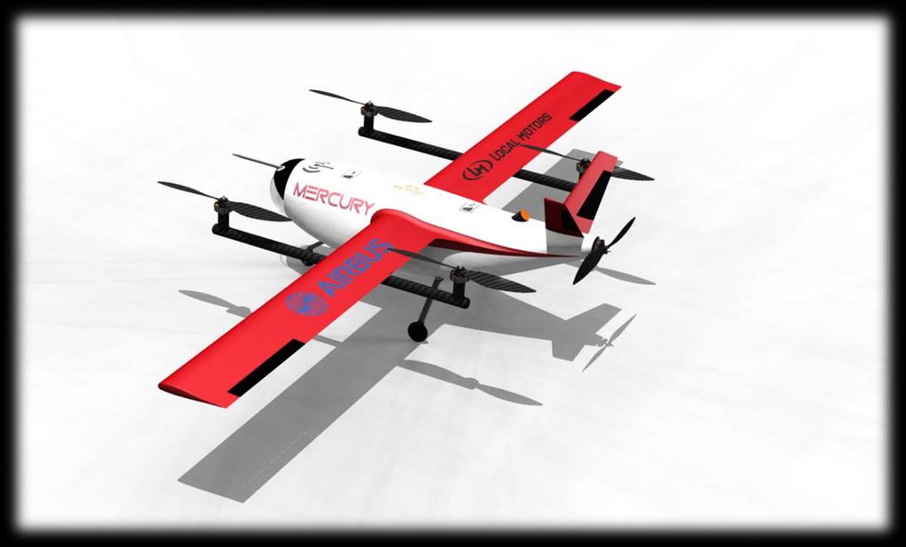
1 Local Motors Airbus Cargo Drone Challenge mercury Simple, stable, safe Author and designer: Sergio González Fernández (Local Motors user Sergius ) Updated May 25, 2016
2 Contents Summary... 3 Introduction... 5 General design... 5 Details... 5 Landing gear... 5 Waterproofness... 6 Modularity/Versatility:... 6 Handling... 9 Weight... 9 Fail safe (air)... 9 Safety provisions (ground)... 9 Dimensions Structure Airframe (fuselage, wings, tail) Equipment (batteries, motors, actuators) Avionics Landing gear concept Payload Interior dimensions and securing cargo Frame sheet Base data Drag Stability Isometric views Appendix A: Frame sheet Appendix B: Mercury UAV operations manual
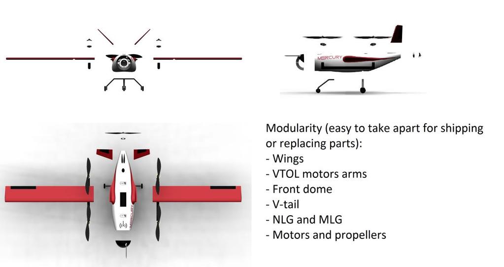
3 Summary General design: a simple VTOL conventional plane. 4+1 big props, minimal interference between components, optimized for the required mission Detail: Landing gear: tricycle type, nose LG + main LG on the belly, avoiding the cargo bay Waterproofness: rubber sealants in joints, waterproof materials and motors Modularity/Versatility: nose dome, wing halves, LG, V-tail, motors arms, equipment, motors, props and cargo bay (attached with spring buttons) easily taken apart Handling: easy to transport and fit in reduced spaces Weight: CG aligned with motors, payload, IMU and parachute, < 25 kg, structure allowed up to 7 kg, carries around 1 extra required payload weight Fail safe (air): all kinds of redundancy, anti-collision, mission control planning and anticatastrophic failure software readiness Safety provisions (ground): safety switch to arm/disarm drone, RGBW LED indicator, optional props protections Dimensions: the wing is 4 m long, divided in 2 parts, fuselage is 2 m long and 0.85 m high with V-tail and LG Structure Payload Frame sheet Airframe (fuselage, wings, tail): all secondary parts joined to main fuselage CFRP frame with screws and nuts able to be taken apart Equipment (batteries, motors, actuators): 4 hover motors and 1 cruise pusher required with their adapted propeller, ESC and the necessary batteries Avionics: correctly integrated and centered boxes given in the requirements Landing gear concept: nose CFRP straight bar and main CFRP trapezoidal frame with wheels (steerable NLG) Interior dimensions and securing cargo: cargo bay has required dimensions and a fairing around that completes the fuselage aerodynamic shape. It is secured by an antislip floor plus elastic bands. It s released by sliding 4 spring buttons below Base data: 4 to 6 kg of payload at 30 m/s with a medium CL Drag: low drag increases range (or payload weight) 3
4 Stability: stabilizing wings shape and position, NP at 18% behind the CG gives enough stability 4
5 Introduction Mercury cargo drone is a VTOL UAV able to deliver 4 to 6 kg of payload to 100 or 60 km in 55 to 35 minutes with an optimal configuration. It has a very simple configuration, cheap and easy to manufacture and able to change its whole payload bay to adapt its mission. General design The whole aircraft is designed with many years of experience from aerospace design guidelines, focusing on this special payload and an overall simplicity. A cylindrical fuselage is shaped around the equipment of the UAV, keeping its wetted area and front area reduced to decrease drag. It contains the avionics, miscellaneous equipment, batteries and payload. The nose is a clear translucent spherical dome that houses the camera, able to look straight down to the ground (-90 deg.) up to 50 degrees up from the horizon without distortion or darkening. A single straight wing with 4 meters of wingspan (divided in 2 separate halves) crosses the middle fuselage over the payload, the empennage is a V-tail type requiring 2 surfaces, hence just 2 actuators, to control the pitch and yaw. A T-tail with similar dimensions is also considered in the performance calculations although it might be difficult the launch of the parachute. 4 motors hanging from the wing with carbon bars can lift the UAV in hovering mode. They have interference with the airflow on cruise flight but it is minimal as circular bars don t create much disturbance and the propellers are placed above the airflow line over the wing. Depending on the mission, the payload bay can carry multiple types of equipment: agriculture monitoring, infrastructure inspection, humanitarian missions (fast and heavy duty delivery), firefighting control, ground observation for law enforcement or coast control, transport of medical items, 3D terrain reconnaissance, weather monitoring The name comes from the Roman god of commerce, messages and communication, coming from the word merchandise. The red and white colors come from health related typology. Details Landing gear The landing gear is a fixed tricycle type, available in many RC stores with many different frame and wheels dimensions. Being fixed avoids moving parts that can cause problems and it is not a big issue added to the parasite drag as it won t fly over 200 km/h. It is located at the sides of the payload bay hatch, close to the center of gravity and allowing an easy extraction of the module from below. It is designed to be as short as the payload unloading process allows for minimizing parasite drag. The landing gear increases not just the safety but also the versatility of the UAV. If one or both departure and arrival locations count with a small runway the UAV itself can carry 1.3 kg more of payload (reduced batteries) and if the lifter motors (not even 5
 to reduce drag force and increase autonomy, they must have a proper landing station or trust the controller to perform always a")
6 their arms) are unscrewed to act as a plane, it saves 2 kg more. Weight saving can also be transformed in more batteries and an increased range/autonomy. In case the clients want to remove the landing gear (easily unscrewed) to reduce drag force and increase autonomy, they must have a proper landing station or trust the controller to perform always a soft landing on the UAV belly fairing (cushioned payload bay recommended for fragile cargo). The landing gear can be much lower (or higher) if needed depending on the landing station. If the unloading process is automated and from below, the station may not require such a high frame. The wheels are thought to have cowlings on the upper side to reduce interference drag. Waterproofness The exposed surfaces are mainly made of composite materials and plastics that withstand the rain effects or even a dive in water with rubber sealants in every small joint and wire hole. The major material, present in the fuselage and aerodynamic surfaces, is fiberglass reinforced polymer, whose epoxy resin can stand water on its surface. All hatches have rubber sealants too. All landing gear materials, as stated in the structure part, work well under moisture and rain environments. The motors are tested again water and dirt by the manufacturer, as expected from the exposed air data probe and parachute elements. Modularity/Versatility: The payload bay is completely removable with its own fairing. It can be enlarged to the tail and can be accessed easily from the belly and from the bottom tail. It is encased into small rail holes from bottom to top and from left to right of the fuselage and secured with 2 spring buttons on the sides. The payload bay can carry the batteries too, so the swap operation just requires unloading the bay, unplugging the batteries wires, plug the new ones and attach the new bay. This is another optional feature offered to the client. 6
.")

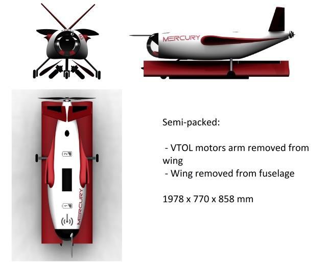
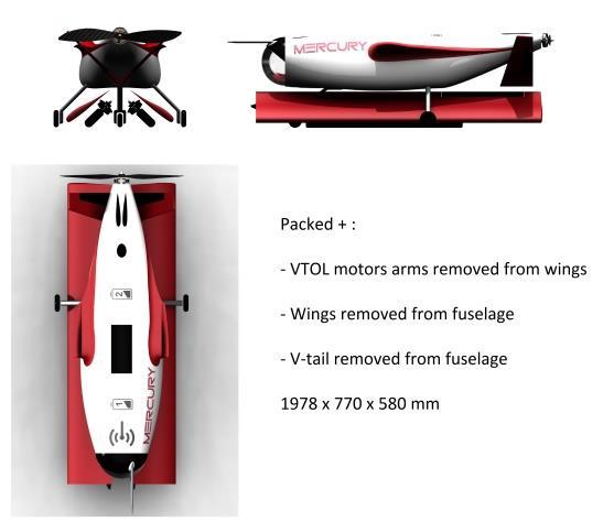
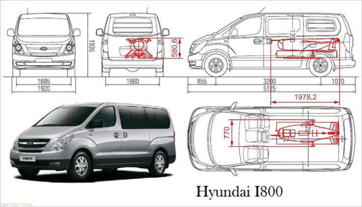
7 The whole middle fuselage frame can also be replaced for other applications, although it requires detaching the main structure. This allows changing its wing, lifter motors with arms and landing gear if necessary (keeping the front frame with avionics and the rear frame with empennage and pusher motor). Besides, every motor and propeller can be changed with just a screwdriver. For shipping purposes it is enough to remove the wings and the motors arms and put them between the landing gear. The fuselage with the air data antenna and the rear propeller is shorter than 2 meters. If it needs to be even more packed the V-tail can be removed too, making it almost 30 cm lower in height. Properly packed it is estimated that 4 Mercurys packed in this configuration can be fitted in a regular transport van (E.g. Hyundai I800). 7
8 8
9 Handling The drone can be lifted with ease by the forward arms in the wing by 2 people, as the CG is before the wing. The wing tips or the nose and tail are good support points too. Thanks to the high tail configuration, the UAV can be put standing on its tail just lifting the nose and rotating it around the main landing gear (CG position over MLG). This allows a further inspection of the belly fairing and access to the payload bay. Weight The MTOW is set to <25 kg and the structure weighs less than 7 kg. The heaviest parts are in the CG or close to increase stability. Lifter motors are away from the CG to keep stability in take-off and landing but not too far along the wingspan so the spars can be lighter. The main CFRP structure (density = 1.66 g/cm 3 ) weighs 1.6 kg with a plate thickness of 2 mm, the glass fiber cover (density = 1.52 g/cm 3 ) weighs 2.8 kg and the rest of components as motors arms and landing gear weigh 1.6 kg, summing up to less than 6 kg. Fail safe (air) To prevent crashes in case of one or more motors failure, propeller separation, power loss or bird strike, an automatic deployment parachute and launcher are provided, apart from the installation of a landing gear that allows an emergency landing with just the pusher motor or even gliding. This landing gear absorbs better the force of a hard landing than typical multirotor skids. The high aspect ratio of the wing grants a good gliding ability to this UAV apart from the excellent lift to drag ratio. In any case, the batteries are segregated in the system, so if one battery fails it just affects 2 hover motors at most, or just the cruise motor. As it is not supposed to fly over water in accordance to its range, no floating devices or water skis are designed. The own software of the flight control computer has a failsafe option that starts a controlled landing in case it detects a low voltage in any of the batteries, if the signal with the ground control station is weak/lost, if the mission parameters are lost or if the UAV has entered too much inside a restricted geo-fence. The controlled landing will be performed in hover mode if hover batteries have enough charge and all 4 motors are operative. If any of the hover motors fail, the UAV will execute a conventional landing with the cruise pusher motor and if no motors are operative and the parachute can t be deployed (worst case scenario) the UAV will glide to the ground with just the assistance of the control surfaces. Every emergency case will be notified to ground control. Mission control must plan the route in advance to study the possible obstacles the UAV might find. To avoid mid-air collisions with buildings, trees or other UAVs, apart from creating navigation routes as in large aircraft transport, the UAV can be built with a small sonar/infrared sensor and/or a TCAS (Traffic alert and Collision Avoidance System) in conjunction with other RPAS. Safety provisions (ground) Propeller protections are avoided in further versions because another system replaces them, with the related reduced parasite drag and harder manual payload access from the side. It consists of a safety switch located below the nose that prevents the rotors to spin via a 9

10 connection to the flight control computer. However, the protections are designed by the manufacturer and are optional for the client, who might want to install them if the UAV is going to be operated by people and not an automated system. These protections will be efficiently shaped for reduced drag, keeping similar parasite drag as the propellers alone would cause. The fuselage has indications in the hatches providing the instructions to handle the equipment. An RGBW LED light next to the safety switch will indicate personnel in ground when the drone is ready to be safely approached. In this location it doesn t dazzle people close to it but still illuminates enough reflecting on the ground. Red means the UAV is armed and executing the mission, green means it is ready to be operated by ground personnel, blue means safety switch is on and it is safe to load/unload it. The LED will be flashing white during the mission to act as an anti-collision beacon, especially for nighttime operations. When the UAV is unpowered the LED will be off. The whole walk-around time is less than 15 minutes. More info on pre-flight checklist manual attached as an appendix. LED and safety switch below the nose 10
11 Dimensions Structure Airframe (fuselage, wings, tail) Semi-monocoque structure: CFRP lightweight frames, decks, bars and spars provide the necessary strength in torsion, flexion, traction and compression along the longitudinal fuselage axis, along the wingspan, empennage and lifter motors arms. Vertical and horizontal decks are joined with plastic joints and metal screws. The main fuselage airframe and hatches are covered with 5 mm of fiberglass, CFRP is avoided in the cover because it shields the radio signals. The aerodynamic surfaces are made of hot wire cut foam blocks (EPP or EPO) reinforced internally and externally with CFRP. The wings have a wing root fairing (wing fillet) to reduce interference drag with the fuselage surface and increase the strength when bending. Straight and conventional shapes make the manufacturing and versatility very easy. Each of the 3 modules the fuselage is divided in is attached with joints between the bars, as well as all the aerodynamic surfaces and their spars. A monocoque or bone-shaped structure is not considered now as it inhibits modularity and is harder to manufacture. 11


12 The high wing above the cargo and center of gravity provides more stability, has no interference with the internal equipment/structure at all and allows an easy access to the payload from below. Similar explanation goes for the position of the motors, focusing always 12
13 on safety (structural, flight stability or effects to ground personnel) and ease of handling. No additional surfaces like winglets or strakes are added as they don t increase the overall efficiency of the UAV at this flight mode and speed. They reduce the induced drag increasing the parasite drag, complexity and manufacturing costs, so they are not considered for the base version. The V-tail control doesn t create any problem with modern autopilot controllers, it has the necessary volume for both static and dynamic stability, it is far from the ground to avoid hits in case of a tail strike in a bad balanced or hard landing, it leaves enough space for deployment of the parachute and it isn t affected by any turbulent flow from forward elements (fuselage, wings or motors). The whole tail surfaces can be trimmed to adapt to the weight and position of the payload. The control surfaces can be trimmed even easier by turning a screw in the servo control rod, changing its leaver arm length. The fuselage shape, while being easy to manufacture and built with divisions from the rest of structural elements, is slender enough to keep drag low, shorter than 2 m, has soft transitions between its elements, allows good air flow for the pusher motor and keeps the center of gravity in the same plane section for lift and thrust. The motors arms under the wing are attached to the wing spar, not far from the wing root to decrease the lift forces but far enough to have a good roll control in hover mode. They enable a rear attachment of another tail in case the payload bay is resized to specific needs. Equipment (batteries, motors, actuators) Many batteries are needed to power the cargo drone. It is estimated that 5 LiPo batteries need to be carried to give energy to the motors and rest of systems. Each one is mah capacity, 20C discharge, 6S cells and 1.6 kg heavy. Battery efficiency is kept low (155 W h/kg), even if the manufacturer says it is higher in order to be conservative and because the efficiency when it is installed is reduced. To make it fly, 4 motors attached to the inboard wing lift 25 kg at standard conditions and one pusher motor in the rear end gives the necessary cruise speed (150 km/h) to gain wing lift and to overcome drag. Lifter motors chosen model is T-motor U10 kv100 (400g each), from the efficiency series, giving 8 kg force maximum thrust each. The pusher motor is the U8-10 kv170 (239 g), giving a maximum thrust of 4.7 kg force. U8 PRO specifications are missing from the manufacturer website but they might be even better except for heavier weight. All motors have the same carbon fiber propeller from the same manufacturer (28 x 9.2 inches) which provide their peak thrust to weight efficiency (~10). They all work well with a 6S or 12S battery pack. Carbon fiber propellers give the best efficiency and need to rotate slower than wooden propellers. U10 motors need a 30A ESC (4 x 44 g) in case they run at maximum voltage (44.4 V with the 12S batteries), because the maximum current will be 24.4 A). U8 pusher maximum current with 22.2 V (6S batteries) will be 23.8 A, so another 30A ESC is needed for cruise. If the pusher uses 12S batteries, it is recommended to install a 20 x 6 wooden propeller instead of the CF one. Sharing the propellers and ESC for all 5 motors allows a good interchangeability. The hover propellers are set parallel to the symmetry plane when the cruise mode begins to reduce their parasite drag. The hover motors have cowlings around them for the same reason but the cruise motor doesn t, as it will be running for more than 30 minutes between half and 13


 and U8 (pusher)")
14 full throttle and may overheat even with air inlets. It is recommended by the manufacturer not to cover it and it is designed with its own patented self-cooling shape. U10 (lifters) and U8 (pusher) specifications 30 A ESC inside carbon tube 14

15 Every propeller is attached to the shaft with the adapted assembly provided by the manufacturer, the same assembly of bedplate they provide to screw it to the structure. In the case of lifters, the arms that hang from the wings are reinforced to resist the motors force on the edge they are screwed at. In the case of the pusher, it is attached to a strong flat frame at the rear end of the fuselage. The rear end can house an internal combustion engine if the UAV user wants to extend its range/autonomy at the cost of carrying fuel instead of batteries. Lifter motors are placed higher than the wings to avoid interference drag, to increase stability and to avoid sucking dust, sand or small rocks. In case of uncontained blade liberation, none of the blade would cause a catastrophic failure thanks to their location. 4 actuators (rotary servomotors) are used, one for each aileron and one for each ruddervator. Actuators for the ailerons act asymmetrically, the same for the ruddervators when controlling yaw and symmetrically actuated ruddervators for pitching. Ailerons controlled symmetrically can act as flaps for landing and take-off in conventional flight mode. That sums up to 4 control channels, plus 5 other channels for the motors. One more channel is needed for manually deploying the parachute, another one for manually controlling the transition process and some extra ones to additional actions like arming the drone or overriding the safety switch. Actuator below the wing moving the aileron 15
 of electric form (KERS style, to")
16 Additional power sources are being studied to recharge batteries during flight: an electric generator driven by the cruise motor inboard axis, solar panels on the wing upper skin, vortex/bladeless wind energy generators, autorotation landing that takes energy when descending either in kinetic (inertia can be used for an emergency landing as in an autogiro) of electric form (KERS style, to recharge batteries with the necessary power for a soft landing). Another system in development which can be implemented to this operation is a selfrecharging UAV. It has connections in the landing gear that create a bridge between a battery charger in the landing station and the batteries electrical system, automating the charging operations of the drone. It can be charged by induction too when it approaches the landing base like cell phone wireless chargers and it works very fast. This combined with an automated unloading/loading process turns the whole operation completely unmanned. Avionics The center of gravity axis is shared by the payload, the battery pack, the inertial measurement unit (IMU) and the parachute, all of them accessed from top or below. The IMU can go inside the structure of the wing between spars or a bit forward to avoid interference. The rest of equipment provided in the requirements has its own reserved space in the nose (the camera inside the translucent dome as well as the air data probe and antennas) and the forward fuselage, which helps taking the CG forward and reduces the wiring among elements. Transmitting and receiving antennas (flight control, video, GPS) will be placed as far apart as possible once they are known, so the interference and signal noise doesn t represent an issue. 16


17 Landing gear concept The landing gear frame is made of fiberglass straight bars (or CFRP), bearings are made of stainless steel and wheels are made of rubber. The nose landing gear wheel has a free rotation axis which doesn t increase weight significantly and allows turning in a possible taxi phase. The frames are wide enough to absorb huge landing forces and transmit them to the main structure. Both nose and main landing gears are screwed to the structure. 17

18 Payload Interior dimensions and securing cargo Payload bay is designed to be larger than the required dimensions. When the payload boxes inside the cargo bay are smaller than these requirements they are secured by many possible means, taking into account they won t be heavier than 6 kg. From simpler to more complex: a rough rubber floor on the bay module that prevents shifting of the CG along axis X and Y could be enough, viscoelastic polyurethane foam (memory foam or LRPu), cable ties, elastic strings and finally a mechanism of plates that move along rails with springs (similar to universal battery chargers or sliding cellphones, 2 plates below press the boxes along the Y axis and 2 plates above press it along the X axis). Inside the enabled boxes for the client, vertical and horizontal plastic separators are included to place each item evenly spaced and unable to shift (e.g. blood samples, syringes, medicines ). CG shifting won t be an issue. 18

19 The cargo bay is removed by sliding 4 spring buttons on the belly of the UAV, next to the corners of the module, 2 at a time. 19

20 Frame sheet Base data Every time a performance value is fixed, it s in the mind of the designer being conservative with the numbers, with safety margins to reduce future errors and added design cost during the project. This is referred mainly but no limited to: battery specific energy, efficiencies, structure and equipment weight, dimensions, wing surface, lift and drag coefficients. Every value is rounded and increased/decreased to the safety side. Ignition kit s frame sheet is attached at the end as an appendix. The main figures are these: Payload Mass m Payload = m TOM m empty = 4.4 kg for 100 km 6.18 kg for 60 km Cruise Speed v cruise = 33.3 m/s 20


21 Speed equals 120 km/h. These aspects are explained in the appendix. Due to iterations, design pictures may not match this data. The most updated data is the one coming from the frame sheet. Drag Parasite drag is obtained from Digital DATCOM formulas, Roskam and Raymer methods, mixing this geometry with coefficients coming from laminar and turbulent Reynolds tests as well as form and interference factors of several aerodynamic shapes. For the V-tail version: The optimal lift coefficient for minimal drag is 0,7 but obviously for a negative pitch angle around 2 degrees down. This is the CL and gliding angle the UAV might have to boost its autonomy. Total induced and parasite drag sums the total cruise drag and thrust required by the motor to overcome it. CD0 0, For the T-tail version: 21


22 CD0 0, Stability The center of gravity can be easily changed moving the battery packs along the longitudinal axis. By design they are placed close to the payload, at the front and rear sides, but each pack has an extra space for another pack further from the CG, making it more able to be shifted. In addition, the neutral point could be set much backwards with a little change in the wing or tail design or position in this modular frame to increase the longitudinal stability. A high wing increases stability and the V-tail (and T-tail option) avoids interference with the airflow, the same reason why lifter motors are quite higher than the wing plane. 22


23 For V-tail empennage: Lift coefficients for the wing and tail surfaces are obtained with their relative position and geometry with Digital DATCOM formulas. They are dimensionless, referred to the dynamic pressure and the wing surface. In addition, the interference of the wing over the tail (downwash) is obtained too with empirical formulas and coefficients. It is negative because the wing flow decreases the relative angle of attack of the tail. All the geometry put together with their lift coefficients and downwash effect gives the neutral point position, or combined center of lift. 23
.")

24 A positive static margin means the neutral point is behind the CG, making the UAV selfstabilizing in pitch (statically stable). Over 10% is already enough stability. This is checked with the value of the total moment coefficient (values between -0.8 and -1.5 are adequate). As the CG is a bit further of the center of lift of the main wing, the tail needs to pitch the UAV up to compensate the moment. This small pitching is used to balance the thrust vector around the CG too. Last calculations give the needed negative angle for the tail to compensate all moments. It is less than a degree because the lift and weight forces are very close to each other in the wing. The chart in the right gives additional notions of tilting the tail in case the wing is pitched up to increase lift. For example, if the UAV must fly slower to save battery weight, the wing will need to have a higher lift coefficient to compensate the decrease in speed. Tilting the wing up 2 24


25 degrees for example will give much more lift but the tail must be tilted down 3.3 degrees, as seen in the chart. For T-tail empennage (more stable, more drag): 25

26 Isometric views 26
27 Appendix A: Frame sheet Airbus Cargo Drone Challenge Frame Sheet Sergio González Fernández (User Sergius) Version... V 2.00 Last Update Aircraft Data: Green cells are calculated by formulars or are given (not changeable) requirement values e cells are specific to the design entry; mandatory to be filled out by the participant as delivery item Blue cells are optional delivery items Aircraft name : Mercury General Requierements Description Symbol Value Unit Comment Maximum Take-Off Mass mmtom = 25,0 kg Shall stay below 25 kg Air Density r= 0, m MSL and ISA+20 C Geometry Data: Description Symbol Value Unit Comment Wing Span b = 3,6 m Not counting the wingspan inside the fuselage wh c = 0,3 Aspect Ratio AR = 12 - Wing Area Sref = 1,08 m² Wing Loading (fixed wing mode) m/sref = 23, kg/m² kg/m² recommendation Disc Loading (rotor disc) m/sprop Lift = 15, kg/m² kg/m² recommendation Lift Propeller Area per Lift Propeller Sprop Lift = 0,397 m² Lift Propeller Diameter Dprop Lift = 0,711 m Cruise Propeller Diameter Dprop Cruise = 0,7112 m Cruise Propeller Area per Cruise Propeller Sprop Cruise = 0,40 m Number of Propeller for Hover npropeller,hover = 4 - Number of Propeller for Cruise npropeller,cruise = 1 - Fuselage Length Lfuselage= 2 m Fuselage Diameter (max. Diameter) Dfuselage= 0,55 m Vertical Tail Surface Svertical tail = 0,17 m² V-tail values, T-tail has almost the same lengths an Vertical Tail Leaver Arm to CoG lvertical tail = 0,85 m Horizontal Tail/Canard Surface Shorizontal tail = 0,2 m² Horizontal Tail/Canard Leaver Arm to CoG lhorizontal tail = 0,85 m Control Curface Area for Pitch Scontrol,pitch = 0,06 m² Control Surface Leaver Arm to CoG for Pitch lcontrol,pitch = 0,95 m Control Surface Area for Roll Scontrol,roll = 0,056 m² Control Surface Leaver Arm to CoG for Roll lcontrol,roll = 2 m Control Surface Area for Yaw Scontrol,yaw = 0,03 m² Control Surface Leaver Arm to CoG for Yaw lcontrol,yaw = 0,9 m Mass and Balance Data: Description Symbol Value Unit Comment Structural Mass (wing, fuselage, empenage, nacelles, ) mstruct = 7 kg Avionics Mass (see ignition kit) mavionics = 3,4 kg PDF values sum 3,26805kg, default was 3,4 Flight Control Actuation mactuation = 0,55 kg Electric Motors and Controllers Mass (for hover) mmotors,hover = 1,776 kg 4 x T-motor U x Turnigy multistar 30A ESC Electric Motors and Controllers Mass (for cruise) mmotors,cruise = 0,68 kg Turnigy multistar 30A ESC Propellers Mass (for hover) mpropeller,hover = 0,4 kg 4 x T-motor 28x9.2 CF Propellers Mass (for cruise) mpropeller,cruise = 0,1 kg T-motor 28x9.2 CF Battery Mass mbattery = 4,416 kg Additional Mass for Installations minstalltions = 0,5 kg mass for wiring, installations, etc. Empty Mass å mempty = 18,822 kg Payload Mass d = mmtom - mempty = 6,18 kg Center of gravity location x-location xcog = 0,75 m From the nose. (Payload at 0,75 m) y-location ycog = 0 m z-location zcog = 0,046 m Height from the center longitudinal axis (X) of the 27
28 Efficiencies: Description Symbol Value Unit Comment Efficiencies for Hover Flight Electrical Motor Efficiency (incl. Motor controller efficiency) helect. motor = 88% Figure of Merit FOM = 0,6 - Battery Efficiency hbattery = 97% Power Management and Distribution Efficiency hpmad = 99% Efficiencies for Cruise Flight Electrical Motor Efficiency (incl. Motor controller efficiency) helect. motor = 88% Propeller Efficiency hpropeller = 82% Battery Efficiency hbattery = 97% Power Management and Distribution Efficiency hpmad = 99% Aerodynamics: Description Symbol Value Unit Comment Oswald Factor e = 0,86 - Zero Lift Drag Coefficient CD0= 0,015 - Cruise Lift Coefficient CL Cruise= 0,43 - Induced Drag Coefficient CDi Cruise= 0,01 - Lift to Drag Ratio L/DCruise = 20,74 - Static Margin SM = 18% Component specific Energy: Description Symbol Value Unit Comment Battery Specific Energy wbattery = 155,0 Wh/kg Aircraft Range Performance Estimation: Description Symbol Value Unit Comment Required Cruise Thrust Tcruise = 11,8 N Cruise Speed vcruise = 33,3 m/s Range drange = 60,0 km Required Cruise Power Pcruise = 567,5 W Hover nz nz= 1,1 - Required Hover Power Phover = 4775,5 W Required Power for Avionics PAvionics = 93,0 W previously 91W, without ADS Cruise Time tcruise = 35,0 min including 5 min reserve Hover Time thover = 2,0 min 2 min Hover time is required Battery Energy Ebattery = 547,6 Wh Some values are left unchanged, like the structure mass, the efficiencies, battery specific energy and installation, actuation and avionics masses (although avionics mass seemed to be a bit lower in the ignition it). The wingspan is the effective one for the purpose of correct lift results (real wingspan is 4 meters but some is inside the fuselage and another bit is affected by the lifter motors arms). Wing and disc loadings are obtained from the dimensions of their elements, not the other way around. They are later checked to be between the recommended values. The wing surface is set to be enough to lift the MTOW at the desired cruise speed but not so big in order to keep a low drag and reduced size. The propellers are big as they give the highest efficiencies with the 28
 but also the lift coefficient required by the wing.")
29 chosen batteries for the recommended motor by the manufacturer. Their masses are introduced in the mass section. CD 0 is adapted to the one calculated. Cruise speed is set to fit the required payload (more speed, more battery weight, less payload) but also the lift coefficient required by the wing. Flying slower requires a higher CL which can only be achieved by certain complex (cambered) airfoils. In this chart (set for a range of 60 km) it s shown what CL might be needed at a given speed and how much payload the UAV could carry. Going for a CL value of 0.46 (not pessimist neither optimist), the UAV should fly at 110 km/h to carry 6 kg. If the aircraft can achieve a real higher CL value (for the whole aircraft, not just the wings), it should be able to carry more payload by flying slower. It always depends of what we have, how much does out payload weigh and how quick we want to arrive. v(km/s) v(m/s) CL Pcruise Ebatt Wbatt Payload 80 22,2222 0, , ,236 3, , , , ,824 3, , ,7778 0, , ,412 3, , ,5556 0, , , , ,3333 0, , ,588 4, , ,1111 0, , ,176 4, , ,8889 0, , ,764 4,861 5, ,6667 0, , ,352 5, , ,4444 0, , ,94 5, , ,2222 0, , ,527 5, , , , ,115 5, , ,7778 0, ,58 740,703 5, , ,5556 0, , ,291 6,1959 4,4 Payload weight comparison for a 60 km mission Here are some of the other frame sheets built to calculate weights centering, lift and drag performance, flight conditions, airfoils polar curves, induced and parasite drag approximations, missions, design point and stability. They have become master spreadsheets for the preliminary design of UAVs. 29
30 Appendix B: Mercury UAV operations manual Preflight inspection checklist (at base level), 10 min 1. Check batteries voltage, for each one if they are segregated (avionics equipment, VTOL and cruise motors, camera ) 2. Flight equipment visual inspection (walk around) (UAV unpowered, LED off): a. Controller/Transmitter check for damage b. Structure check: i. From nose to tail and from top to bottom, no apparent cracks ii. Wings and control surfaces are intact, no leading/trailing edge or wingtip damage iii. Same for empennage surfaces iv. Landing gear presents no damage or deformation c. VTOL motors arms hold tight to the wings d. All 5 motors turn freely, are tightly screwed to the structure e. Propellers are correctly attached and don t have any scratches, dents, bending or chips 3. Connect power to autopilot 4. Connect power to avionics 5. Check-ins from Ground Station a. Check telemetry b. Check RC signal c. Check avionics connection d. Check compass e. Check level horizon f. Check GPS g. Check airspeed h. Check altitude i. Check mission uploaded to flight control computer: vertical take-off, transition, cruise, transition back and vertical landing 6. Check safety switch off, check arming is secured 7. Turn safety switch on (UAV safe and powered, LED on blue) 8. Check response of control surfaces is correct in direction, time and speed 9. Check auto-stabilization from gyroscopes 10. Connect power to motors (UAV on stand-by, LED on green) 11. Close and secure all access hatches (avionics and camera bay, batteries 1&2 bays, payload bay) 12. Bring UAV to take-off zone 13. Check operation zone is cleared from people, animals and obstacles 14. Check the weather conditions, avoid flight in too windy conditions, heavy rain, snow, hail 15. Check the take-off, landing and route locations don t enter in the reserved space for airports according to the country s legislation 30
31 16. Check possible wireless networks and antennas interference 17. Arm UAV (UAV armed, LED on red and flashing white) 18. Start mission - VTOL to cruise transition phase - - Cruise to VTOL transition phase - Cargo transport mission: Arrival destination checklist (at client level), 5 to 15 min. (some steps are optional) 1. Bring replacement batteries (charged) (UAV armed, LED on red and flashing white) 2. Disarm UAV (UAV on stand-by, LED on green) 3. Turn safety switch off (UAV safe and powered, LED on blue) 4. Check safety switch off, check arming is secured 5. Bring UAV to unloading zone 6. Open batteries 1&2 hatches 7. Disconnect power to motors (UAV unpowered, LED off) 8. Extract batteries (discharged) 9. Open payload bay hatch 10. Extract payload and put aside 11. Insert replacement batteries (charged) 12. Open avionics hatch 13. Check batteries voltage, for each one if they are segregated (avionics equipment, VTOL and cruise motors, camera ) 14. If UAV encountered problems during operation, such as hazardous weather or hard landing: a. Follow step 2 from preflight inspection checklist (Flight equipment visual inspection) 15. If voltage is not enough: a. Disconnect power from autopilot and avionics b. Change their batteries c. Follow steps 3, 4 and 5 from preflight inspection checklist 16. Follow steps 6 to 12 from preflight inspection checklist (UAV on stand-by) 17. Arm UAV 18. Start mission 19. Remove payload from unloading zone 20. Connect discharged batteries to charger 31
Local Motors Airbus Cargo Drone Challenge
 Local Motors Airbus Cargo Drone Challenge Small, efficient, secure Author and designer: Sergio González Fernández (Local Motors user Sergius ) Updated May 25, 2016 Contents Summary... 3 Introduction...
Electric Penguin s philosophy:
 UNMANNED PLATFORMS AND SUBSYSTEMS Datasheet v 1.1 Penguin BE Electric Unmanned Platform Up to 110 minutes of endurance 2 with 2.8 kg payload 23 liters of payload volume Quick replaceable battery cartridge
PENGUIN B UAV PLATFORM
 UNMANNED PLATFORMS AND SUBSYSTEMS Datasheet v.0 PENGUIN B UAV PLATFORM Penguin B platform ready for payload and autopilot integration 0+ hour endurance Fuel injected engine option Up to 10 kg payload capacity
Minerva A Spanloader Concept
 Minerva A Spanloader Concept by D. Felix Finger M.Sc. in Aerospace Engineering In Response to the Airbus Cargo Drone Challenge Contents 1 Requirements... 3 2 Design Inspiration... 4 2.1 Three-view... 4
Electric VTOL Aircraft
 Electric VTOL Aircraft Subscale Prototyping Overview Francesco Giannini fgiannini@aurora.aero 1 08 June 8 th, 2017 Contents Intro to Aurora Motivation & approach for the full-scale vehicle Technical challenges
Ultralight airplane Design
 Ultralight airplane Design Ultralight airplane definitions: Airworthiness authorities define aircraft as vehicles that can rise or move in the air and enforce strict regulations and requirements for all
Aircraft Design: A Systems Engineering Approach, M. Sadraey, Wiley, 2012 Chapter 11 Aircraft Weight Distribution Tables
 Aircraft Design: A Systems Engineering Approach, M. Sadraey, Wiley, 01 Chapter 11 Aircraft Weight Distribution Tables No Component group Elements Weight X cg Y cg Z cg 1 Wing 1.1. Wing main structure 1..
How to use the Multirotor Motor Performance Data Charts
 How to use the Multirotor Motor Performance Data Charts Here at Innov8tive Designs, we spend a lot of time testing all of the motors that we sell, and collect a large amount of data with a variety of propellers.
A SOLAR POWERED UAV. 1 Introduction. 2 Requirements specification
 A SOLAR POWERED UAV Students: R. al Amrani, R.T.J.P.A. Cloosen, R.A.J.M. van den Eijnde, D. Jong, A.W.S. Kaas, B.T.A. Klaver, M. Klein Heerenbrink, L. van Midden, P.P. Vet, C.J. Voesenek Project tutor:
Warning! Before continuing further, please ensure that you have NOT mounted the propellers on the MultiRotor.
 Mission Planner Setup ( optional, do not use if you have already completed the Dashboard set-up ) Warning! Before continuing further, please ensure that you have NOT mounted the propellers on the MultiRotor.
AERO. Meet the Aero. Congratulations on your purchase of an Aero!
 AERO Congratulations on your purchase of an Aero! Please read the following sections of this manual to get started with your new autonomous aircraft. 1 Meet the Aero 7 Fly-by-wire mode 2 Safety 8 Command
Design Considerations for Stability: Civil Aircraft
 Design Considerations for Stability: Civil Aircraft From the discussion on aircraft behavior in a small disturbance, it is clear that both aircraft geometry and mass distribution are important in the design
AERO. Meet the Aero. Congratulations on your purchase of an Aero!
 AERO Congratulations on your purchase of an Aero! Please read the following sections of this manual to get started with your new autonomous aircraft. 1 Meet the Aero 7 Fly-by-wire mode 2 Safety 8 Command
AT-10 Electric/HF Hybrid VTOL UAS
 AT-10 Electric/HF Hybrid VTOL UAS Acuity Technologies Robert Clark bob@acuitytx.com Summary The AT-10 is a tactical size hybrid propulsion VTOL UAS with a nose camera mount and a large payload bay. Propulsion
XIV.C. Flight Principles Engine Inoperative
 XIV.C. Flight Principles Engine Inoperative References: FAA-H-8083-3; POH/AFM Objectives The student should develop knowledge of the elements related to single engine operation. Key Elements Elements Schedule
Theory of Flight. Main Teaching Points. Definition Parts of an Airplane Aircraft Construction Landing Gear Standard Terminology
 Theory of Flight 6.01 Aircraft Design and Construction References: FTGU pages 9-14, 27 Main Teaching Points Parts of an Airplane Aircraft Construction Standard Terminology Definition The airplane is defined
Air Buzz. 32nd Annual AHS International Student Design Competition
 Air Buzz 32nd Annual AHS International Student Design Competition Faculty Advisor: Dr. Daniel Schrage, Daniel.Schrage@aerospace.gatech.edu Ezgi Selin Akdemir esakdemir@gmail.com Undergraduate Middle East
Appenidix E: Freewing MAE UAV analysis
 Appenidix E: Freewing MAE UAV analysis The vehicle summary is presented in the form of plots and descriptive text. Two alternative mission altitudes were analyzed and both meet the desired mission duration.
Rotary Wing Micro Air Vehicle Endurance
 Rotary Wing Micro Air Vehicle Endurance Klaus-Peter Neitzke University of Applied Science Nordhausen, Nordhausen, Germany neitzke@fh-nordhausen.de Abstract One of the first questions to pilots of rotor
L 298/70 Official Journal of the European Union
 L 298/70 Official Journal of the European Union 16.11.2011 MODULE 12. HELICOPTER AERODYNAMICS, STRUCTURES AND SYSTEMS 12.1 Theory of Flight Rotary Wing Aerodynamics 1 2 Terminology; Effects of gyroscopic
Radio control glider
 Radio control glider Contents SPECIFICATIONS 01 STATEMENT 02 SAFETY PRECAUTIONS 02~03 CHARGING METHOD AND CAUTIONS 03~05 ASSEMBLY 06~07 2.4GHz RADIO SYSTEM 08~10 PRE-FLIGHT INSPECTION AND ADJUSTMENT 10~11
International Journal of Scientific & Engineering Research, Volume 4, Issue 7, July ISSN BY B.MADHAN KUMAR
 International Journal of Scientific & Engineering Research, Volume 4, Issue 7, July-2013 485 FLYING HOVER BIKE, A SMALL AERIAL VEHICLE FOR COMMERCIAL OR. SURVEYING PURPOSES BY B.MADHAN KUMAR Department
1.1 REMOTELY PILOTED AIRCRAFTS
 CHAPTER 1 1.1 REMOTELY PILOTED AIRCRAFTS Remotely Piloted aircrafts or RC Aircrafts are small model radiocontrolled airplanes that fly using electric motor, gas powered IC engines or small model jet engines.
Instruction Manual MUSTANG P51 - EP. Wingspan : 1377mm (54.21in) : 1180mm (46.46 in) : 2200gr gr. : AXI motor 2826 or 4120
 : 1180mm (46.46 in) : 2200gr gr. : AXI motor 2826 or 4120") Instruction Manual MUSTANG P51 - EP Wingspan : 1377mm (54.21in) g Length : 1180mm (46.46 in) Weight : 2200gr - 2600gr Engine : AXI motor 2826 or 4120 Radio : 4 channel / 4 servos standard KIT CONTENTS:
Instruction Manual MUSTANG P51 - EP Wingspan : 1377mm (54.21in) g Length : 1180mm (46.46 in) Weight : 2200gr - 2600gr Engine : AXI motor 2826 or 4120 Radio : 4 channel / 4 servos standard KIT CONTENTS:
RECOMMENDED MOTOR AND BATTERY SET UP
 SPECIFICATION - Wingspan: 6000mm (236.2 in) - Length: 2873mm (113.1 in) - Flying weight: 14-18 kg - Wing area: 219.4 dm2 - Wing loading: 64g/dm2 - Wing type: HQ airfoils - Covering type: Genuine ORACOVER
Please read all instructions carefully before assembly and flight!
 Please read all instructions carefully before assembly and flight! Thank you for purchasing the Mig-15. This model is designed for the intermediate to advanced flyer. The model is receiver ready and includes
FIRE PHOENIX RADIO CONTROLLED AIRPLANE
 FIRE PHOENIX RADIO CONTROLLED AIRPLANE ASSEMBLY AND OPERATION INSTRUCTIONS YIN YAN MODEL TECH. MFT. 1 SPECIFICATIONS Material EPO Plane Battery Li-Po 1300mAh 11.1V Radio 4 Channel Wing Span 1200mm Length
Assembly and Operating Manual. SPECIFICATION Length inch (640mm) Wing Span inch (705mm) Flying Weight oz (330g)
 Wing Span inch (705mm) Flying Weight oz (330g)") Assembly and Operating Manual SPECIFICATION Length 25.19 inch (640mm) Wing Span 27.76 inch (705mm) Flying Weight 11.64 oz (330g) Dear customer, Assembly and Operating manual VIPER The Radio Control System
Assembly and Operating Manual SPECIFICATION Length 25.19 inch (640mm) Wing Span 27.76 inch (705mm) Flying Weight 11.64 oz (330g) Dear customer, Assembly and Operating manual VIPER The Radio Control System
ROBUST AIRFRAME FOR UAV FLIGHT TESTING FOR SALE!
 ROBUST AIRFRAME FOR UAV FLIGHT TESTING FOR SALE! My team specializes in fabricating airframes that s appropriate for testing unmanned aerial vehicle components. Our airframes are made of hybrid composite
Investigative Technologies and Techniques
 Investigative Technologies and Techniques Using Drones In Accident Investigation (Aerial Photography) Drone used in accident investigation Technical specifications and performance Flat 8 motor configuration
Brief introduction
 P-51D MUSTANG Brief introduction----------------------------------------------------------------------------03 Specifications---------------------------------------------------------------------------------03
Climber is 776B101101
 is Climber 776B101101 Introduction Product Introduction NE R/C 776B is a good-sized glider designed by Nine Eagles Company latest, whose wing span is up to 2008mm. You only need to assemble the aerofoil
Assembly and Operating Manual. 3D cap-232. Specification: *Length: 25-9/10"(655mm) *Wing Span: 29-3/5"(750mm) *Flying Weight: 15-9/10 oz (450g)
 *Wing Span: 29-3/5(750mm) *Flying Weight: 15-9/10 oz (450g)") Assembly and Operating Manual 3D cap-232 Specification: *Length: 25-9/10"(655mm) *Wing Span: 29-3/5"(750mm) *Flying Weight: 15-9/10 oz (450g) Dear customer, Congratulations on your choice of a factory-assembled
Assembly and Operating Manual 3D cap-232 Specification: *Length: 25-9/10"(655mm) *Wing Span: 29-3/5"(750mm) *Flying Weight: 15-9/10 oz (450g) Dear customer, Congratulations on your choice of a factory-assembled
Methodology for Distributed Electric Propulsion Aircraft Control Development with Simulation and Flight Demonstration
 1 Methodology for Distributed Electric Propulsion Aircraft Control Development with Simulation and Flight Demonstration Presented by: Jeff Freeman Empirical Systems Aerospace, Inc. jeff.freeman@esaero.com,
SAFETY INSTRUCTIONS. 1. Please read this manual carefully and follow the instructions of the manual before you use this products.
 INSTRUCTION MANUAL 1. Please read this manual carefully and follow the instructions of the manual before you use this products. SAFETY INSTRUCTIONS 2. Our airplane is not a toy, which is only suitable
This manual covers all color schemes Although it only shows one color scheme, the aircraft are the same This manual is for reference to the actual
 This manual covers all color schemes Although it only shows one color scheme, the aircraft are the same This manual is for reference to the actual product at the time it was written. We can't speak for
12.1 Theory of Flight Rotary Wing Aerodynamics 1 2
 12.1 Theory of Flight Rotary Wing Aerodynamics 1 2 Terminology; Effects of gyroscopic precession; Torque reaction and directional control; Dissymmetry of lift, Blade tip stall; Translating tendency and
BY HOEYCOMB AEROSPACE TECHNOLOGIES. HC-330 HYBRID-POWERED ALL- ELECTRICITY DRIVEN four-rotor UAV
 BY HOEYCOMB AEROSPACE TECHNOLOGIES HC-330 HYBRID-POWERED ALL- ELECTRICITY DRIVEN four-rotor UAV Content SYSTEM SPECIFICATI- ON TYPICAL USING PROCESS OVERVIEW SUBSYSTEM SPECIFICATI- ON 1 OVERVIEW System
64MM F-16 Fighting Falcon V2
 64MM F-16 Fighting Falcon V2 SIMPLE Simple assembly RIGID STRONG DURABLE EPO STABLE SMOOTH FLYING PERFORMANCE FMSMODEL.COM Table of Contents Introductions 3 Contents of Kit 4 Assemble the plane 5 Battery
I n s t r u c t i o n M a n u a l. Instruction Manual SPECIFICATION
 I n s t r u c t i o n M a n u a l Instruction Manual SPECIFICATION - Wingspan: 3200mm (125,9 in) - Length: 1650mm (64,9 in) - Flying weight: 3000gr 3200gr - Wing area: 64.5 dm2 - Wing loading: 46g/dm2
Airframes Instructor Training Manual. Chapter 6 UNDERCARRIAGE
 Learning Objectives Airframes Instructor Training Manual Chapter 6 UNDERCARRIAGE 1. The purpose of this chapter is to discuss in more detail the last of the Four Major Components the Undercarriage (or
Prop effects (Why we need right thrust) Torque reaction Spiraling Slipstream Asymmetric Loading of the Propeller (P-Factor) Gyroscopic Precession
 Torque reaction Spiraling Slipstream Asymmetric Loading of the Propeller (P-Factor) Gyroscopic Precession") Prop effects (Why we need right thrust) Torque reaction Spiraling Slipstream Asymmetric Loading of the Propeller (P-Factor) Gyroscopic Precession Propeller torque effect Influence of engine torque on aircraft
Prop effects (Why we need right thrust) Torque reaction Spiraling Slipstream Asymmetric Loading of the Propeller (P-Factor) Gyroscopic Precession Propeller torque effect Influence of engine torque on aircraft
INDEX. Preflight Inspection Pages 2-4. Start Up.. Page 5. Take Off. Page 6. Approach to Landing. Pages 7-8. Emergency Procedures..
 INDEX Preflight Inspection Pages 2-4 Start Up.. Page 5 Take Off. Page 6 Approach to Landing. Pages 7-8 Emergency Procedures.. Page 9 Engine Failure Pages 10-13 Propeller Governor Failure Page 14 Fire.
High aspect ratio for high endurance. Mechanical simplicity. Low empty weight. STOVL or STOL capability. And for the propulsion system:
 Idealized tilt-thrust (U) All of the UAV options that we've been able to analyze suffer from some deficiency. A diesel, fixed-wing UAV could possibly satisfy the range and endurance objectives, but integration
The Airplane That Could!
 The Airplane That Could! Critical Design Review December 6 th, 2008 Haoyun Fu Suzanne Lessack Andrew McArthur Nicholas Rooney Jin Yan Yang Yang Agenda Criteria Preliminary Designs Down Selection Features
Y. Lemmens, T. Benoit, J. de Boer, T. Olbrechts LMS, A Siemens Business. Real-time Mechanism and System Simulation To Support Flight Simulators
 Y. Lemmens, T. Benoit, J. de Boer, T. Olbrechts LMS, A Siemens Business Real-time Mechanism and System Simulation To Support Flight Simulators Smarter decisions, better products. Contents Introduction
RECOMMENDED EDF AND BATTERY SET UP
 SPECIFICATION - Wingspan: 1150mm (45.3 in) - Length: 1587mm (62.5 in) - Flying weight: 5.0-5.3 kg - Wing area: 40dm2 - Wing loading: 125g/dm2 - Wing type: Naca airfoils - Covering type: Genuine ORACOVER
Powertrain Design for Hand- Launchable Long Endurance Unmanned Aerial Vehicles
 Powertrain Design for Hand- Launchable Long Endurance Unmanned Aerial Vehicles Stuart Boland Derek Keen 1 Justin Nelson Brian Taylor Nick Wagner Dr. Thomas Bradley 47 th AIAA/ASME/SAE/ASEE JPC Outline
Assembly and Operating Manual HR-100. Specification: *Length: 41-7/10"(1060 mm) *Wing span: 49-1/5"(1250 mm) *Flying weight: 45.
 *Wing span: 49-1/5(1250 mm) *Flying weight: 45.") Assembly and Operating Manual HR-100 Specification: *Length: 41-7/10"(1060 mm) *Wing span: 49-1/5"(1250 mm) *Flying weight: 45.9 oz (1300g) Dear customer, Congratulations on your choice of a factory-assembled
Assembly and Operating Manual HR-100 Specification: *Length: 41-7/10"(1060 mm) *Wing span: 49-1/5"(1250 mm) *Flying weight: 45.9 oz (1300g) Dear customer, Congratulations on your choice of a factory-assembled
Instruction Manual For intermediate to advanced pilots
 Instruction Manual For intermediate to advanced pilots SAFETY INSTRUCTIONS 1. Please read this manual carefully and follow the instructions before you use this product. 2. This airplane is not a toy, due
In response to. 34th Annual AHS International Student Design Competition IIT KANPUR INDIAN INSTITUTE OF TECHNOLOGY, KANPUR
 In response to 34th Annual AHS International Student Design Competition By 2017 VIBHRAM AIRFRAME 4-VIEW ISOMETRIC TOP FRONT SIDE HELICOPTER SYSTEMS OVERVIEW Landing Gear Light weight and high strength
Lip wing Lift at zero speed
 Lip wing Lift at zero speed Dusan Stan, July 2014 http://hypertriangle.com/lipwing.php dusan.stan@hypertriangle.com HyperTriangle 2014 Lip_wing_Lift_at_zero_speed_R2.doc Page 1 of 7 1. Introduction There
Chapter 3: Aircraft Construction
 Chapter 3: Aircraft Construction p. 1-3 1. Aircraft Design, Certification, and Airworthiness 1.1. Replace the letters A, B, C, and D by the appropriate name of aircraft component A: B: C: D: E: 1.2. What
Super Squadron technical paper for. International Aerial Robotics Competition Team Reconnaissance. C. Aasish (M.
 Super Squadron technical paper for International Aerial Robotics Competition 2017 Team Reconnaissance C. Aasish (M.Tech Avionics) S. Jayadeep (B.Tech Avionics) N. Gowri (B.Tech Aerospace) ABSTRACT The
Please read all instructions carefully before assembly and flight!
 c c Please read all instructions carefully before assembly and flight! Thank you for purchasing the. This model is designed for the intermediate to advanced flyer. The model is receiver-ready and includes
DRONE & UAV.
 www.erapkorea.co.kr DRONE & UAV Extended flight time Proven to be reliable, safe and easy to use Various fields of operation Completely autonomous, and manually controlled ERAP DRONE & UAV WHY ERAP s MAPPING
Strix Goblin Instruction Manual. Rev
 Strix Goblin Instruction Manual Rev 3-4.24.2017 1 Introduction Thank you for purchasing the Strix Goblin! This is a high performance plank style aircraft and it was designed using aerodynamic principles
1100MM P-51 Mustang ELECTRIC POWERED REMOTE CONTROL AIRPLANE ELEVENHOBBY.COM
 1100MM P-51 Mustang ELECTRIC POWERED REMOTE CONTROL AIRPLANE ELEVENHOBBY.COM WARNING: Read the ENTIRE instruction manual to become familiar with the features of the product before operating. Failure to
A practical investigation of the factors affecting lift produced by multi-rotor aircraft. Aaron Bonnell-Kangas
 A practical investigation of the factors affecting lift produced by multi-rotor aircraft Aaron Bonnell-Kangas Bonnell-Kangas i Table of Contents Introduction! 1 Research question! 1 Background! 1 Definitions!
Clean Sky 2. LifeCraft Demonstrationt (IADP RC 2 & ITDs) Consultation meetings Brussels th December 2012 OUTLINE
 Consultation meetings Brussels th December 2012 OUTLINE") Clean Sky 2 LifeCraft Demonstrationt (IADP RC 2 & ITDs) Consultation meetings Brussels 10-14 th December 2012 1 1 LifeCraft - The Compound Demo OUTLINE Presentation of the Compound R/C Concept Impact &
Clean Sky 2 LifeCraft Demonstrationt (IADP RC 2 & ITDs) Consultation meetings Brussels 10-14 th December 2012 1 1 LifeCraft - The Compound Demo OUTLINE Presentation of the Compound R/C Concept Impact &
I/C FLIGHT GUIDELINES
 SPECIFICATION - Wingspan: 3500mm (137.8 in) - Length: 1650mm (64.96 in) - Flying weight: 3700-4000 gr - Wing area: 75 dm2 - Wing loading: 49g/dm2 - Wing type: HQ profile - Covering type: Genuine ORACOVER
Performance means how fast will it go? How fast will it climb? How quickly it will take-off and land? How far it will go?
 Performance Concepts Speaker: Randall L. Brookhiser Performance means how fast will it go? How fast will it climb? How quickly it will take-off and land? How far it will go? Let s start with the phase
70MM YAK-130 STABLE SMOOTH FLYING PERFORMANCE FMSMODEL.COM
 70MM YAK-130 REALISTIC RETRACT & FLAPS INSTALLED RIGID STRONG DURABLE EPO STABLE SMOOTH FLYING PERFORMANCE FMSMODEL.COM Table of Contents Introductions 3 Contents of Kit 4 Assemble the plane 5 Battery
Assembly and operating instructions. Assembly and Operating Manual
 Assembly and operating instructions Assembly and Operating Manual Dear customer, Assembly and Operating Manual The radio control system Glued joints, suitable adhesives Congratulations on your choice of
CHAPTER 11 FLIGHT CONTROLS
 CHAPTER 11 FLIGHT CONTROLS CONTENTS INTRODUCTION -------------------------------------------------------------------------------------------- 3 GENERAL ---------------------------------------------------------------------------------------------------------------------------
Dragon Eye. Jessica Walker Rich Stark Brian Squires. AOE 4124 Configuration Aerodynamics
 Dragon Eye Jessica Walker Rich Stark Brian Squires Outline Purpose/Mission Air Vehicle Configuration Airfoil Data Planform Data Aerodynamic Characteristics Assessment Purpose / Mission: Real-Time Imagery
RECOMMENDED MOTOR AND BATTERY SET UP
 SPECIFICATION - Wingspan: 1404mm (55.3in) - Length: 1134mm (44. 6 in) - Flying weight: 3.2-3.4 kg - Covering type: Genuine ORACOVER - Spinner size: scale type (not included) - Radio: 4 channel minimum
Aeroplane Aerodynamics and Flight Controls 1 2
 11.1 Theory of Flight 11.1.1. Aeroplane Aerodynamics and Flight Controls 1 2 Operation and effect of: roll control: ailerons and spoilers, pitch control: elevators, stabilators, variable incidence stabilisers
DSSI UAV. Unmanned Aerial Vehicle. Research & Development Project
 UAV Unmanned Aerial Vehicle HISTORY AND SKILLS of Small UAV with electrically powered propeller Description of the solution: Airframe,electronics, 2 battery sets 1 spare Airframe, battery charger Transport
SAFETY WARNING Please read these before operating your Sky Vector
 www.megatech.com Entire contents Megatech 2002 Congratulations! You have just purchased the EASIEST plane to fly in the world! Learning to fly has never been so fun! Get ready to hand launch into gravity-defying
ITEMS INCLUDED. 2.4GHz Controller
 READ THESE INSTRUCTIONS BEFORE FLYING! ITEMS INCLUDED.4GHz Controller Flight Battery Charger SKY Cruiser LiPo Flight Battery AA Batteries AC Power Supply WARNINGS FOR YOUR SAFETY PLEASE READ AND UNDERSTAND
CONTENTS. Introduction 1. Features 1. Specification 1. Contents 2. Tools And Items 3. Assembly of the front landing gears 4
 CONTENTS Introduction 1 Features 1 Specification 1 Contents 2 Tools And Items 3 Assembly of the front landing gears 4 Assembly of horizontal tail & 5 vertical tail and tail wheel Assembly of main wings,
 Introduction Thank you for purchasing a Redcat P-51 model R/C aircraft! Headquartered in Phoenix, AZ; Redcat Racing is proud to have become the premier source for quality Gas, Nitro and Electric powered
Program Goals and Objectives/Instructional Design. Title: Beyond Multi-Copters: Transitioning the New Drone Pilot to Fixed Wing Aircraft
 Program Goals and Objectives/ Design Title: Beyond Multi-Copters: Transitioning the New Drone Pilot to Fixed Wing Aircraft Instructor: James M. Page, LeTourneau University and Seraphim Aerial Program Goal:
Cessna 172P PPL Checklist Page 1
 Cessna 172P PPL Checklist 06-08-2017 Page 1 Cessna 172P PPL Checklist 06-08-2017 Page 2 Checklist Items Informational Items Critical Memory Items PREFLIGHT COCKPIT CHECK (DO-LIST) Pitot Cover -- REMOVE
Systems Group (Summer 2012) 4 th Year (B.Eng) Aerospace Engineering Candidate Carleton University, Ottawa,Canada Mail:
 4 th Year (B.Eng) Aerospace Engineering Candidate Carleton University, Ottawa,Canada Mail:") Memo Airport2030_M_Family_Concepts_of_Box_Wing_12-08-10.pdf Date: 12-08-10 From: Sameer Ahmed Intern at Aero Aircraft Design and Systems Group (Summer 2012) 4 th Year (B.Eng) Aerospace Engineering Candidate
Memo Airport2030_M_Family_Concepts_of_Box_Wing_12-08-10.pdf Date: 12-08-10 From: Sameer Ahmed Intern at Aero Aircraft Design and Systems Group (Summer 2012) 4 th Year (B.Eng) Aerospace Engineering Candidate
7. PRELIMINARY DESIGN OF A SINGLE AISLE MEDIUM RANGE AIRCRAFT
 7. PRELIMINARY DESIGN OF A SINGLE AISLE MEDIUM RANGE AIRCRAFT Students: R.M. Bosma, T. Desmet, I.D. Dountchev, S. Halim, M. Janssen, A.G. Nammensma, M.F.A.L.M. Rommens, P.J.W. Saat, G. van der Wolf Project
AVRO LANCASTER by Ivan Pettigrew Construction Notes
 AVRO LANCASTER by Ivan Pettigrew Construction Notes For ease of transportation, the model may be built with the wing in three sections. The sections are held together with nylon clips. Assembly at the
FIRST FLYING TECHNIQUES COCKPIT PREPARATION STARTUP TAXI
 1. Introduction FIRST FLYING TECHNIQUES COCKPIT PREPARATION STARTUP TAXI We aim to teach and demonstrate how to operate a general aviation aircraft and show some basic techniques and manoeuvres that every
Assembly and Operating Manual
 Dear customer, Assembly and Operating Manual The radio control system Glued joints, suitable adhesives Congratulations on your choice of a factory-assembled model aircraft from the SKYANGEL Hummingbird
Assembly and operating instructions. Assembly and Operating Manual
 Assembly and operating instructions Assembly and Operating Manual Dear customer, Assembly and Operating Manual The radio control system Glued joints, suitable adhesives Congratulations on your choice of
UAV Systems Comparison. Planes, Frames and Autopilots
 UAV Systems Comparison Planes, Frames and Autopilots Presenter: Robert Lefebvre BASc Mechanical Engineering, University of Ottawa Managing Director NOVAerial Robotics Inc. Ardupilot Developer 6 Years UAV
the leading edge of the wing, at the fuselage - Length: 1540mm (60.6 in) 10% expo; High: 15mm up/down, 10% expo - Wing area: 40dm2
 10% expo; High: 15mm up/down, 10% expo - Wing area: 40dm2") SPECIFICATION - Gravity CG: 165-170 mm (6.5-6.7 in) Back from - Wingspan: 1400mm (55.1 in) the leading edge of the wing, at the fuselage - Length: 1540mm (60.6 in) - Control throw Ailerons: Low: 12mm up/down,
SPECIFICATION - Gravity CG: 165-170 mm (6.5-6.7 in) Back from - Wingspan: 1400mm (55.1 in) the leading edge of the wing, at the fuselage - Length: 1540mm (60.6 in) - Control throw Ailerons: Low: 12mm up/down,
Length Height Rotor Diameter Tail Rotor Diameter..12. Tail Boom Length Width
 2.1 Air Vehicle 2.1.1 Vehicle General Description The PA-01 Vapor S-UAV is a rotary wing small unmanned aerial vehicle. The AV is powered by an outrunner 8.5hp class brushless electric motor. The airframe
The implementation of highly advanced and efficient +25 kw RESLS - Retractable Electric Self-Launching System,
 The GP 14 E/SE VELO is the ultimate expression of 13.5 meter FAI racing class fully flapped and ballasted, combined with everyday usability traits and features. The implementation of highly advanced and
A Game of Two: Airbus vs Boeing. The Big Guys. by Valerio Viti. Valerio Viti, AOE4984, Project #1, March 22nd, 2001
 A Game of Two: Airbus vs Boeing The Big Guys by Valerio Viti 1 Why do we Need More Airliners in the Next 20 Years? Both Boeing and Airbus agree that civil air transport will keep increasing at a steady
INDIAN INSTITUTE OF TECHNOLOGY KANPUR
 INDIAN INSTITUTE OF TECHNOLOGY KANPUR INDIAN INSTITUTE OF TECHNOLOGY KANPUR Removable, Low Noise, High Speed Tip Shape Tractor Configuration, Cant angle, Low Maintainence Hingelesss, Good Manoeuverability,
 Introduction Thank you for purchasing a Redcat JETiger Ducted-Fan Aircraft! Headquartered in Phoenix, AZ; Redcat Racing is proud to have become the premier source for quality Gas, Nitro and Electric powered
FINWING TECHNOLOGY WWW. FINWINGHOBBY. PATENT PENDING
 FINWING SABRE 1900 USER MANUAL FINWING TECHNOLOGY WWW. FINWINGHOBBY. COM PATENT PENDING Finwing Sabre Please read through the manual carefully before installation and flying This manual aims to help direct
TABLE OF CONTENTS. Chapter 1, Introduction Chapter 2, Helicopter and Systems Description and Operation. 4. Chapter 3, Avionics.
 TABLE OF CONTENTS TITLE PAGE NO. Chapter 1, Introduction... 4 Chapter 2, Helicopter and Systems Description and Operation. 4 Chapter 3, Avionics. 4 Chapter 4, Mission Equipment. 4 Chapter 5, Operating
Innovating the future of disaster relief
 Innovating the future of disaster relief American Helicopter Society International 33rd Annual Student Design Competition Graduate Student Team Submission VEHICLE OVERVIEW FOUR VIEW DRAWING INTERNAL COMPONENTS
Interior Pre Flight Documents: Check Control Wheel Lock: Remove Flight Controls: Check Instruments: Check for Damage Switches: Verify All Off Master
 Interior Pre Flight Documents: Check Control Wheel Lock: Remove Flight Controls: Check Instruments: Check for Damage Switches: Verify All Off Master Switch ALT/BAT: On Fuel Gauge: Check Quantity Flaps:
Overview. Mission Overview Payload and Subsystems Rocket and Subsystems Management
 MIT ROCKET TEAM Overview Mission Overview Payload and Subsystems Rocket and Subsystems Management Purpose and Mission Statement Our Mission: Use a rocket to rapidly deploy a UAV capable of completing search
PAC 750XL PAC 750XL PAC-750XL
 PAC 750XL The PAC 750XL combines a short take off and landing performance with a large load carrying capability. The PAC 750XL is a distinctive type. Its design philosophy is reflected in the aircraft's
A-VIATOR (AP68TP 600) Presentation
 Presentation") A-VIATOR (AP68TP 600) Presentation All reasonable care has been taken by VULCANAIR to ensure the accuracy of the information contained in the present document. However, the material presented is provided
A-VIATOR (AP68TP 600) Presentation All reasonable care has been taken by VULCANAIR to ensure the accuracy of the information contained in the present document. However, the material presented is provided
VERT 1 VERTICAL TAKE OFF / LANDING RC PLANE
 VERT 1 VERTICAL TAKE OFF / LANDING RC PLANE THANK YOU. Thank you for your purchase of Protocol s Vert I Vertical Take Off / Landing RC Plane. You are about to experience the best of what remote control
JODEL D.112 INFORMATION MANUAL C-FVOF
 JODEL D.112 INFORMATION MANUAL C-FVOF Table of Contents I General Description...4 Dimensions:...4 Powertrain:...4 Landing gear:...4 Control travel:...4 II Limitations...5 Speed limits:...5 Airpeed indicator
H-King R/C scale model series. instruction manual
 H-King R/C scale model series instruction manual 1. Please read this manual carefully and follow the instructions of the manual before you use this products. SAFETY INSTRUCTIONS 2. Our airplane is not
DESIGN AND DEVELOPMENT OF A MICRO AIR VEHICLE (µav) CONCEPT: PROJECT BIDULE
 CONCEPT: PROJECT BIDULE") DESIGN AND DEVELOPMENT OF A MICRO AIR VEHIE (µav) CONCEPT: PROJECT BIDULE Mr T. Spoerry, Dr K.C. Wong School of Aerospace, Mechanical and Mechatronic Engineering University of Sydney NSW 6 Abstract This
DESIGN AND DEVELOPMENT OF A MICRO AIR VEHIE (µav) CONCEPT: PROJECT BIDULE Mr T. Spoerry, Dr K.C. Wong School of Aerospace, Mechanical and Mechatronic Engineering University of Sydney NSW 6 Abstract This
DEVELOPMENT OF A MORPHING FLYING PLATFORM FOR ADAPTIVE CONTROL SYSTEM STUDY
 27 TH INTERNATIONAL CONGRESS OF THE AERONAUTICAL SCIENCES DEVELOPMENT OF A MORPHING FLYING PLATFORM FOR ADAPTIVE CONTROL SYSTEM STUDY Taufiq Mulyanto, M. Luthfi I. Nurhakim, Rianto A. Sasongko Faculty