Table of Contents 1. Overview... 2
|
|
|
- Susan Kelley
- 5 years ago
- Views:
Transcription
1
2 Table of Contents 1. Overview Design Process Mechanical Design Chassis Drivetrain Weatherproofing Rear Mount Suspension Electrical Design Power Source and Distribution Devices Roboteq AX2550 Motor Controller Emergency Stop On-board Computer Other Components of Interest Overall Design Decisions Layout Power Distribution Component Usage Software Overview Sensors LIDAR Camera IMU GPS Ultrasonic Sensor Array Program Hierarchy Low Level Functions Medium Level Functions High Level Functions Conclusion
3 1. Overview The Stony Brook Robot Design Team is led by an Executive Board consisting of five administrative positions and three engineering team leaders, all undergraduate students. The president, vice president, secretary, treasurer and public relations officer collaborate to take care of the team logistics while the mechanical, electrical and software engineering team leaders oversee the design, fabrication and testing of the competition vehicle. The team leaders report directly to the vice president. The overall hierarchy is shown in Figure 1. Figure 1: Team leadership structure Each vehicle prepared for competition is a collaborative effort. Although P15 was entered into last year s competition as P14, a senior design project from the Department of Mechanical Engineering at Stony Brook University, we have rebuilt some parts and completely retrofitted its interior. 1.1 Design Process A five stage design process was used to design, manufacture, and test our robot. The first step in the design process was competition research. Product Design Specifications (PDS) were created to define the key requirements of the robot. Research and parametric analysis was done on prior robots that competed in IGVC to get a better idea of qualities that we would want in our own robot. The second step was conceptual design. All possible designs were generated and compared by using a set of criteria. An iterative process allowed for the best design to be developed. The third step was detailed design. Sections 2, 3, and 4 will describe the mechanical, electrical and software aspects of the detailed design phase respectively. Each component was justified by a Component Design Specifications (CDS). 2


4 The fourth stage is centered on building the robot. Most of the fabrication was done in a four week period. Examples of machinery that were used include a milling machine, lathe, band saw, and rapid prototype machine. The fifth stage was to test and debug the robot in a systematic manner. Sensors were progressively integrated until every sensor had been added and was working properly. Even though each step had specific guidelines and requirements; each task was not done Figure 2: Design Process Flowchart independently. Often, it became necessary to return to previous steps to modify the system. Graphically, this process is shown in Figure Mechanical Design 2.1. Chassis The chassis of the robot is built from extruded aluminum. The extruded aluminum is easily assembled using right angle brackets, which makes the robot more modular. and easy to change or add parts. In order of to decrease the degrees of freedom as well as increase the strength of the design, the aluminum was milled to have notches, which fit into the channels on other adjacent structural members. Figure 3 shows a CAD drawing of the designed structure. Figure 3: CAD Drawing The second goal was to analyze each component. This was done with Finite Element Analysis (FEA), using Autodesk Inventor. FEA was done on each component designed that would be placed under loading conditions. Special consideration was given to: the locations of stresses, displacement, and factor of safety. An example of this is shown in Figure 4 on the next page. Here, the deflection of the moment arm is considered. 3


5 The displacement is zero at the constrained hole and maximizes where it connects to the wheel. The maximum displacement was shown to be inches. The deformations are within tolerances. The mechanical sub-system is divided into four sections that will be described below. Figure 4: FEA of swing arm suspension member 2.2. Drivetrain This year we decided to modify the sprocket ratio in order to meet the new top speed of 10 mph. Our original ratio was 17:25 which gave us a top speed of around 4 mph, the ratio has been changed to 15:12 which will give us a top speed of around 7 mph. This can be found using the equation: ω 2 = N 1 ω 1 (1) N 2 This gives us the angular velocity which was then used to find the speed using: 60 min V = ω 2 π d w 1 hr 1 mile (2) in This sprocket system drives the center wheels of the robot. The center drive gives us tighter turns; these turns are made easier with the help of the mecanum wheels (shown in Figure 5 below) which have rollers angled at 45 degrees in order to decrease the shear stress on the wheels when turning. The diameter of each shaft that held the wheels had to be determined normalized steel was chosen to be the shaft material. The torque was assumed to be 300 lbf*in even though the actual torque is Figure 5: Powertrain estimated to be 230 lbf*in. The tensile strength, S ut, is 125 kpsi. The distortion energy-goodman criterion was used to find the shaft diameter which is shown in the following equation: 4
6 d = ( 16n π ((4(K fm a ) 2 + 3(K fs T a ) 2 1 ) 2 + (4(K fm m ) 2 + 3(K fs T m ) 2 1 ) 2 )) 1 3 S e S ut (2) The above equation has several unknowns. The factor of safety, n was found to be 3.3. A conservative assumption was made that an end-mill keyset ran through the entire shaft. Because of this distinction: K f = 2.14.Another assumption is made that claims that midrange moments and alternating torques equal 0. In other words: M m = T a = 0. The shoulder fillet, K fs, was assumed to be equaled to 3. The parameter S e = 0.5k a k b k c k d k e k f S ut. It was found that k a = a(s ut /1000) b where a = 2.7 and b = , k b = 0.879d 0.107, and k c = k d = k e = k f =1. Since the diameter the shaft is a component of one of the parameter for its own calculation, an iterative process had to occur. To speed up this process, a program was written in MATLAB so that, each iteration could be ran quickly. The optimum diameter was found to be: 2.3. Weatherproofing d = 1 in. We installed a new weather proofing system, instead of using just plastic to cover the electronics in the chassis, we now use canvas. This canvas is sprayed with a water proofing spray with PTEF, which converts the canvas into a hydrophobic surface. In the event of rain, the droplets will roll off the canvas instead of saturating and permeating it. Using canvas also gave us more room to mount components of the chassis. With our original design components were only mounted in the center of the chassis, with the new weather proofing we are able to mount smaller components on the sides. Along with the canvas covering the top and sides there are plastic plates which cover the front and back. Each of these plates have four holes where fans are mounted on the inside to allow for cooling of the components which tend to overheat, such as the motherboard and motor controller. These fans are oriented so that the flow moves from the front of the robot to the back, the front fans move air in while the back move air out Rear Mount For components that need to be away from electronic/magnetic interference, such as the compass and GPS, and for the cameras which needed to see the front of the robot a tower was assembled. The tower reaches a height of 5 feet which allows the cameras to see not only what is in front of the robot but also the front of the chassis in order to see its position. In order to minimize the vibrations on the mount, the GPS and compass are mounted lower. 5

7 2.5. Suspension In order to minimize vibrations throughout the robot, air shocks are used as suspension. The air shocks are mounted to the chassis of the robot and an arm which holds the front mecanum wheels of the robot. The air shocks can be calibrated for the amount of play wanted by the knobs on the shocks and also by the amount of air added. This year to give the shocks more play we mounted them high and also angled them off from vertical. 3. Electrical Design The electrical portion of Project 15 can be summarized by the power source, devices and the design decisions made behind everything Power Source and Distribution In Figure 6, a basic breakdown of how power is distributed within Project 15 is shown. The robot s main power source is two 12V non-spillable lead acid marine batteries. The marine batteries are capable of providing 300Ah each. Their drawback, however, is their immense 50 lb weight and size. However, the decision was made to use these batteries over lighter and smaller Li-Ion batteries because of their energy storage potential and the Figure 6: Diagram showing distribution of power between convenience of only having to components charge two batteries. Additionally, testing has shown the ability of these batteries to maintain a charge between 11 and 13V while running the robot at full load for long period of time. The two 12V batteries are used to create a roughly 24V source as well as provide a 12V source. Both of these sources are fed directly to most components that require them due to the components having internal power regulation. In situations where a 5V or a regulated 12V source is required, 6
8 small DC-DC converter packs capable of outputting 5V/12V constantly based on variable input are utilized Devices There are various electrical devices utilized in the robot. These devices are mostly commercial off the shelf components. The most important systems formed by the devices are described below Roboteq AX2550 Motor Controller This motor controller directly drives the two brushed DC motors that provide the motion for the robot. The motor controller accepts the raw 24V input for the two motors independently. Additionally, the motor controller is also activated by having 24V applied to a control line. The use of this particular motor controller gives us a variety of features and configurability that also add to the safety to this design. All power management to the motors is performed directly by the motor controller. The device has the ability to handle currents up to 120A on each motor in the worst case. There are also programmable current limits that can be set to limit the current draw. During testing, the motors were measured to draw approximately 20A each under load and so the current limits were set to 40A for each motor. Another safety feature is the ability to constantly require pinging by the computer to remain in motion, otherwise the controller will shut down Emergency Stop The emergency stop system is implemented as required by IGVC competition rules, and for the general safety of the team and public. It is implemented using a series of 3 relays as shown in Figure 7 below. Figure 7: Emergency stop flow diagram The kilovac contactor is a relay in a normally off state until energized by a 12V source. The 12V source is controlled by the wirelessly controlled relay and push button relay. The tripping of 7
9 either of these relays will cutoff power to the kilovac contactor immediately. Once the contactor is turned off, the robot will lose all power to its motors Wireless Relay Module The wirelessly controlled relay is part of a device called the Relay Function Module 2 manufactured by Linux Technologies. It is a box that essentially contains 4 independent relays that can be wirelessly controlled by a remote. One of the available relays is used in the emergency stop module. The relay can be toggled between an on and off state on demand. Additionally, the relay defaults to the off state Pushbutton Reset Module In order to have a pushbutton to act as an emergency stop on the robot itself, a PCB was designed and created to act as a triggerable relay circuit. It was made to be compatible with any kind of pushbutton. The module uses no programmable elements as required by the IGVC rules and instead utilizes basic logic ICs. One designed feature of the module is a permanent shut off of the relay until the module has its power switched toggled off and back on. An additional feature is a 5V logical output that indicates when the emergency stop has been tripped. This allows the onboard computer to respond by shutting down the program Kilovac Contactor The Kilovac LEV200 series contactor is the biggest relay used in the emergency stop circuit. The motor power travels through the relay before it is fed into the motor controller. It is capable of handling up to 500A and its switched by a 12V source On-board Computer From previous entries in the IGVC, we found that an onboard computer system was potentially more reliable than the previous designs using just a laptop. Two of the major issues that the laptop had were excessive power draw and overheating during the summer. The integration of a standard computer motherboard and components has allowed us to build a more reliable computing system. 8
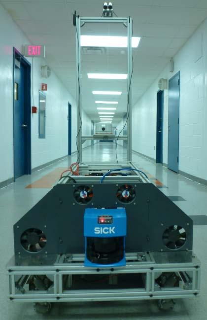
10 M4-ATX Power Supply The most important component besides the motherboard is the computer power supply. This is an off the shelf power supply meant for powering ATX standard motherboards from a DC supply compared to the common AC supplies. It has all the connectors required for the motherboard ATX and CPU connectors, as well as 4-pin MOLEX and SATA power connectors. The power supply is capable of delivering up to 300W at max load and handles all power management of the connected components, making it a perfect component to have been integrated into the design Motherboard The motherboard is the most important part of any computer and the one chosen is an ATX standard desktop motherboard. It has 8GB of memory and an Intel i5 processor. The upside in these choices of specifications is a more powerful computing platform. The downside is the increased power consumption by these components. However, after testing we feel the tradeoff in more power for a reliable system is well worth it Solid State Drive A Solid State Drive (SSD) is utilized due to the elimination of spinning disks utilized in hard disk drives. An issue that exists with using conventional hard drives is that they need to be relatively stable while writing data or else many mechanical problems may occur internally. Hard disk drives are not ideal in environments subjected to vibrations or shock for this reason. The solid state drive is for the most part unaffected by the movement of the robot and a logical choice Other Components of Interest One of the main sensor systems used is the SICK LMS 210. Beyond wiring it to a power source, very little electrical work had to be performed to get it running. Additionally, a compass system to be decided was integrated to provide feedback on the robot s heading. An array of fuses was implemented for the motherboard, motors and LIDAR for a second set of short circuit and overcurrent draw protection Overall Design Decisions There were a few electrical design decisions made in Project 15. They consisted of component layout, power distribution, and components used. 9

11 3.3.1 Layout The component layout on the robot is potentially suboptimal but was decided on as shown in Figure 8. The space between related components was minimized for the ESTOP and computer system. Additionally, the electrical junction block and switches/fuses were put as close to the power source as possible to minimize excess wire. The side with the motor controller was left relatively clear for unrestricted air flow to allow for cooling via forced convection because of overheating concerns Power Distribution The power source created by using the two 12V marine batteries was fed directly to most components. No attempt was made to regulate the voltage fed to the motor controller, LIDAR, and computer power supply. These devices all have Figure 8: Component Layout internal switching based voltage regulation of some form and thus, space is saved by not requiring a large 24V regulator component. In the cases a 5V source was required for the smaller sensor systems (compass), a small DC/DC converter module was wired to 12V to generate the 5V Component Usage The use of off-the-shelf components allowed for an expedited build of the robot. Additionally, the components have more features than would be possible if for example the motor controller was self-built. The AX2550 has a full feature programmable system capable of various operating modes and data. Finally, a cost saving is incurred by using components without having to waste money on prototyping and implementation. 10
12 4. Software 4.1 Overview The layout for this year s robot is focused on the achievement of a fusion of all available sensors as opposed to instinctive and reactionary methods for autonomous navigation. The software structure of the robot is categorized based on a three tier system: Low Mid, and High Functions. This concept was chosen as a fail-safe for ensuring the effectiveness of the robot s navigation system. This was needed due to the fact that as the complexity of the algorithms utilized increased during development. In order to accomplish the concurrent usage of multiple sensors, an onboard computer system was implemented. The embedded system consisted of one high end desktop motherboard with a high performance quad core processor, and ample RAM. The specific system chosen was MIL-SPEC rated for long term use, solid state components (included hard drive) and overall durability in the most demanding of environments. The interlinking of all onboard sensors required a modular and robust device management system that was custom coded. Each device had event-driven connection and data management processes which allowed for worry-free connectivity and data visibility. These new features also provided safety checkpoints during the robot s initialization and autonomous states. Each component was configured so that in case of a disconnection, the robot stops any dangerous actions and displays the state of every part of the robot platform for debugging. 4.2 Sensors LIDAR The on-board LIDAR system is the SICK LMS 221. We utilize the 0.5cm resolution with a scan range of 180 degrees at around 20 feet away from the robot with a refresh rate of 10Hz. The LIDAR driver was built for optimization of data handling, error handling and seamless integration and connection with the LIDAR. A separate Comport manager was created which was designed to ping comports and attempt to establish connections between any drivers that are registered with the manager. 11
13 4.2.2 Camera The computer vision system is comprised of two Microsoft LifeCam Cinema cameras placed at a known distance apart on a five foot boom in the rear of the robot. The cameras faced downward at a specific angle so that the furthermost edge of the robot is the only portion of the chassis visible in the camera systems field of view. This placement allows for the detection of obstacles in and around the robot with a focus on its blind spots IMU The Inertial Measurement Unit utilized is the X-IO ARHS IMU system imported from the UK. This device contains 3 accelerometers, 3 gyroscope and 3 compasses with an advanced Kalman filter for near perfect noise removal. All measurement devices on the unit are at 16 bit resolution which will give more than enough accuracy and precision in terms of measuring the forces on or by the robot as well as the direction and geographic heading GPS The onboard GPS system is the Raven Invicta 115 Marine GPS. It utilizes the WAAS DGPS system with a final accuracy of about 1.4 meters with all satellites in sight. We chose this model due to its powerful antenna, waterproof design, and ability to use the DGPS ground station system with standard NEMA communication protocols Ultrasonic Sensor Array An array of ultrasonic range finders with a terminal range of about 60cm was placed around the perimeter of the robot. The devices utilized were less expensive versions of the Parallax PING))) ultrasonic range finder and were attached to an Arduino Mega 2560 for co-processing. 4.3 Program Hierarchy Low Level Functions The LIDAR system is implemented in its simplest state and scans the area around the robot and notes obstacles of interest based on reading size and proximity to robot. The Initial LIDAR scan data manager categorizes obstacles by proximity into three groups, negligible, mid-range, and close range 12
14 The Camera system performs its basic function and obtains images of the course in front of the robot. The images are blurred to create a more uniform distribution of color on the floor in front of the robot. The system then performs a Hough Transformation to detect lines on the ground. Initial Camera Data Manager creates an array of points from the images that contain the x and y position of each pixel detected by the Hough Transformation. The GPS unit obtains positional data and plots a bread crumb trail of where the robot was with the point of origin being when the robot first initiated its autonomous mode. The Initial GPS data manager uses a Kalman filter to remove any noise from the GPS data to give a more accurate reading. The IMU system obtains data of the three-dimensional forces sensed during the motion of the robot in terms of acceleration. The Inertial Data Manager uses the acceleration data to calculate the displacement of the robot using the following equations: x = x o + V x t a xt 2 y = y o + V y t a yt 2 z = z o + V z t a zt 2 x,y,z = current displacement xo, y o, z o = initial position V x, V y, V z = the velocity a=acceleration t = time since start The ultrasonic array uses sound waves to detect obstacles of close proximity (<60 ) for use with navigation at the immediate level. The Ultrasonic Data Manager plots the points around the robot in the form of a heat map which visually depicts the range of objects in a quick and comprehensible manner. During the autonomous state, the graphical heat map will be suppressed but the data will still remain virtually as an addition to the LIDAR scans as an overlay Medium Level Functions The stereoscopic nature of the camera system will provide a disparity (depth) map of the images acquired which will give true-to-life distances from every part of the detected white lines to the robots center. Using a specific printed glyph, the cameras are each calibrated for distance detection in a manner similar to the Microsoft XBOX Kinect accessory. The flowchart for this process is shown 13

15 in Figure 9. As the robot moves, the LIDAR scans and refreshes the current field of view. Each scan represents the obstacles detected in the environment at that point in time. The scans are then correlated to the displacement of the robot by means of IMU data and a mosaic of data points which provide a simple map of the surroundings High Level Functions A sensor fusion is performed using SLAM algorithms to produce a detailed map of the surroundings using all of the sensors (LIDAR, GPS, IMU, ULTRASONICS, CAMERAS). The data from the LIDAR, cameras, and ultrasonic are overlaid and Figure 9: Disparity Mapping Flowchart aligned to bring further detail about the immediate surroundings and the GPS and IMU give a noise free (by way of Kalman filter) odometry to correlate the relative map with real world coordinates. The GPS waypoints that are given to the robot will act as the bearing for the robot s navigation system, to which the robot will continuously attempt to align itself to a straight line towards the waypoint. This works as a simple GPS navigation system. But in order to perform more intelligent navigation we take the data received from the other sensors and utilize all data to navigate more intelligently. Using the data received from the various sensors, a grid is created and portrays a strict pathable or not pathable grid to the robot. The map will be constructed using a variety of sensors. For example it will take the LIDAR data which is transforming each coordinate the LIDAR from the local, to the world point of view. We can also examine the camera data and perform obstacle recognition on the feed so as to recognize the difference between ground and other obstacles. By using stereoscopic vision we can easily discover obstacles and the distance between them and the robot. Using that we can place these obstacles on the map and consider them in our obstacle avoidance algorithm. Similarly white lines will also be detected by the camera, so we can use transforms and place white lines on our grid of pathable or unpathable. 14
16 From this grid the robot utilizes the A* pathfinding algorithm to estimate the shortest path between our current location and the target location given by the GPS way point. A* works by constructing two lists of nodes: an open list and a closed list. Nodes that have been examined are added to the closed list while nodes that have not yet been examined are on the open list. Initially the only node in the open list is the current node. The node with the smallest path length is picked from the open list and then examined. Nearby walkable nodes are then added to the open list and the process repeats. In this way we are able to construct a path which nearly represents the shortest distance to reach the GPS point. The robot will attempt to travel along the path constructed by the algorithm and the given grid. In order to utilize A* algorithm in an efficient manner there are a couple of speed improvements we can use. Rather than using a grid, we construct a Navigation Mesh which is updated by new obstacles being registered, or obstacles being lost. The navigation mesh speeds up performance by decreasing the number of nodes we traverse via A* as well as accommodate path finding for a robot with some size. As an emergency stop we will implement a function that determines if an obstacle comes within some threshold distance. If this occurs, the robot will attempt to come to an immediate stop and then fully evaluate the situation and then determine the next course of action. This mode will be known as EMode, which will override most navigation functionality to attempt to remove itself from any obstacles it s tangled up in. After it is free, it will then resume normal navigation. 6. Conclusion P-15 was designed, built, and tested to compete in the 2012 Intelligent Ground Vehicle Competition. Physically, our robot was designed to be robust, and yet also mobile enough to be able to navigate around tight corners that may be present during the competition. Sensors were implemented to take the environment and turn it into a series of digital signals that the robot could use to find and negotiate a path through obstacles while staying within line boundaries. Through IGVC we have gained knowledge on the challenges and awards that come from working on a problem as complex as navigation of an autonomous vehicle. 15
UNIVERSITÉ DE MONCTON FACULTÉ D INGÉNIERIE. Moncton, NB, Canada PROJECT BREAKPOINT 2015 IGVC DESIGN REPORT UNIVERSITÉ DE MONCTON ENGINEERING FACULTY
 FACULTÉ D INGÉNIERIE PROJECT BREAKPOINT 2015 IGVC DESIGN REPORT UNIVERSITÉ DE MONCTON ENGINEERING FACULTY IEEEUMoncton Student Branch UNIVERSITÉ DE MONCTON Moncton, NB, Canada 15 MAY 2015 1 Table of Content
INTRODUCTION Team Composition Electrical System
 IGVC2015-WOBBLER DESIGN OF AN AUTONOMOUS GROUND VEHICLE BY THE UNIVERSITY OF WEST FLORIDA UNMANNED SYSTEMS LAB FOR THE 2015 INTELLIGENT GROUND VEHICLE COMPETITION University of West Florida Department
Eurathlon Scenario Application Paper (SAP) Review Sheet
 Review Sheet") Scenario Application Paper (SAP) Review Sheet Team/Robot Scenario FKIE Autonomous Navigation For each of the following aspects, especially concerning the team s approach to scenariospecific challenges,
Scenario Application Paper (SAP) Review Sheet Team/Robot Scenario FKIE Autonomous Navigation For each of the following aspects, especially concerning the team s approach to scenariospecific challenges,
Cilantro. Old Dominion University. Team Members:
 Cilantro Old Dominion University Faculty Advisor: Dr. Lee Belfore Team Captain: Michael Micros lbelfore@odu.edu mmicr001@odu.edu Team Members: Ntiana Sakioti Matthew Phelps Christian Lurhakumbira nsaki001@odu.edu
RED RAVEN, THE LINKED-BOGIE PROTOTYPE. Ara Mekhtarian, Joseph Horvath, C.T. Lin. Department of Mechanical Engineering,
 RED RAVEN, THE LINKED-BOGIE PROTOTYPE Ara Mekhtarian, Joseph Horvath, C.T. Lin Department of Mechanical Engineering, California State University, Northridge California, USA Abstract RedRAVEN is a pioneered
2016 IGVC Design Report Submitted: May 13, 2016
 2016 IGVC Design Report Submitted: May 13, 2016 I certify that the design and engineering of the vehicle by the current student team has been significant and equivalent to what might be awarded credit
Super Squadron technical paper for. International Aerial Robotics Competition Team Reconnaissance. C. Aasish (M.
 Super Squadron technical paper for International Aerial Robotics Competition 2017 Team Reconnaissance C. Aasish (M.Tech Avionics) S. Jayadeep (B.Tech Avionics) N. Gowri (B.Tech Aerospace) ABSTRACT The
Centurion II Vehicle Design Report Bluefield State College
 Centurion II Vehicle Design Report Bluefield State College Ground Robotic Vehicle Team, May 2003 I, Dr. Robert Riggins,Professor of the Electrical Engineering Technology Department at Bluefield State College
RB-Mel-03. SCITOS G5 Mobile Platform Complete Package
 RB-Mel-03 SCITOS G5 Mobile Platform Complete Package A professional mobile platform, combining the advatages of an industrial robot with the flexibility of a research robot. Comes with Laser Range Finder
NJAV New Jersey Autonomous Vehicle
 The Autonomous Vehicle Team from TCNJ Presents: NJAV New Jersey Autonomous Vehicle Team Members Mark Adkins, Cynthia De Rama, Jodie Hicks, Kristen Izganics, Christopher Macock, Stephen Saudargas, Brett
SAE Mini BAJA: Suspension and Steering
 SAE Mini BAJA: Suspension and Steering By Zane Cross, Kyle Egan, Nick Garry, Trevor Hochhaus Team 11 Progress Report Submitted towards partial fulfillment of the requirements for Mechanical Engineering
N.J.A.V. (New Jersey Autonomous Vehicle) 2013 Intelligent Ground Vehicle Competition
 2013 Intelligent Ground Vehicle Competition") N.J.A.V. (New Jersey Autonomous Vehicle) 2013 Intelligent Ground Vehicle Competition Department of Mechanical Engineering The College of New Jersey Ewing, New Jersey Team Members: Michael Bauer, Christopher
N.J.A.V. (New Jersey Autonomous Vehicle) 2013 Intelligent Ground Vehicle Competition Department of Mechanical Engineering The College of New Jersey Ewing, New Jersey Team Members: Michael Bauer, Christopher
Freescale Cup Competition. Abdulahi Abu Amber Baruffa Mike Diep Xinya Zhao. Author: Amber Baruffa
 Freescale Cup Competition The Freescale Cup is a global competition where student teams build, program, and race a model car around a track for speed. Abdulahi Abu Amber Baruffa Mike Diep Xinya Zhao The
GCAT. University of Michigan-Dearborn
 GCAT University of Michigan-Dearborn Mike Kinnel, Joe Frank, Siri Vorachaoen, Anthony Lucente, Ross Marten, Jonathan Hyland, Hachem Nader, Ebrahim Nasser, Vin Varghese Department of Electrical and Computer
iwheels 3 Lawrence Technological University
 5-15-2017 iwheels 3 Lawrence Technological University Team Captain: Devson Butani dbutani@ltu.edu Faculty Advisors: CJ Chung Jonathan Ruszala Gordon Stein Team Members: Sean Bleicher Kevin Cox Nirmit Changani
Princess Sumaya University for Technology
 IGVC2014-E500 Princess Sumaya University for Technology Hamza Al-Beeshawi, Enas Al-Zmaili Raghad Al-Harasis, Moath Shreim Jamille Abu Shash Faculty Name:Dr. Belal Sababha Email:b.sababha@psut.edu.jo I
Oakland University Presents:
 Oakland University Presents: I certify that the engineering design present in this vehicle is significant and equivalent to work that would satisfy the requirements of a senior design or graduate project
TECHNICAL WHITE PAPER
 TECHNICAL WHITE PAPER Chargers Integral to PHEV Success 1. ABSTRACT... 2 2. PLUG-IN HYBRIDS DEFINED... 2 3. PLUG-IN HYBRIDS GAIN MOMENTUM... 2 4. EARLY DELTA-Q SUPPORT FOR PHEV DEVELOPMENT... 2 5. PLUG-IN
DELHI TECHNOLOGICAL UNIVERSITY TEAM RIPPLE Design Report
 DELHI TECHNOLOGICAL UNIVERSITY TEAM RIPPLE Design Report May 16th, 2018 Faculty Advisor Statement: I hereby certify that the development of vehicle, described in this report has been equivalent to the
Gavin Hannah - HND Electronic Engineering Graded Unit Solutions. Christian Hammond, City of Glasgow College. John Woods, City of Glasgow College
 Project Name: SARRRO (Search & Rescue Reconnaissance Rover) Customer: Supervisor: Engineer: Christian Hammond, City of Glasgow College John Woods, City of Glasgow College Gavin Hannah Project Solutions
WHITE PAPER. Preventing Collisions and Reducing Fleet Costs While Using the Zendrive Dashboard
 WHITE PAPER Preventing Collisions and Reducing Fleet Costs While Using the Zendrive Dashboard August 2017 Introduction The term accident, even in a collision sense, often has the connotation of being an
FLYING CAR NANODEGREE SYLLABUS
 FLYING CAR NANODEGREE SYLLABUS Term 1: Aerial Robotics 2 Course 1: Introduction 2 Course 2: Planning 2 Course 3: Control 3 Course 4: Estimation 3 Term 2: Intelligent Air Systems 4 Course 5: Flying Cars
K.I.T.T. KINEMATIC INTELLIGENT TACTICAL TECHNOLOGY
 4/4/2011 SVSU K.I.T.T. KINEMATIC INTELLIGENT TACTICAL TECHNOLOGY Team Members Bryant Barnes Addney Biery Paul List Matthew Plachta Advisor Russell Clark Faculty Advisor Statement I certify that the engineering
SAE Baja - Drivetrain
 SAE Baja - Drivetrain By Ricardo Inzunza, Brandon Janca, Ryan Worden Team 11 Engineering Analysis Document Submitted towards partial fulfillment of the requirements for Mechanical Engineering Design I
Car Technologies Stanford and CMU
 Car Technologies Stanford and CMU Stanford Racing Stanford Racing s entry was dubbed Junior in honor of Leland Stanford Jr. Team led by Sebastian Thrun and Mike Montemerlo (from SAIL) VW Passat Primary
Proudly Presents: Sparta. Intelligent Ground Vehicle Competition Team Members
 Proudly Presents: Sparta Intelligent Ground Vehicle Competition 2011 Team Members Phil Barnett, Dan Bosse, Nick Cappello, Andrew Donihe, Ben Edwards, Takeshi Ei, David Griffin, Steve Hinderlider, Ed Miller,
Detailed Design Review
 Detailed Design Review P16241 AUTONOMOUS PEOPLE MOVER PHASE III Team 2 Agenda Problem Definition Review Background Problem Statement Project Scope Customer Requirements Engineering Requirements Detailed
Club Capra- Minotaurus Design Report
 Table of content Introduction... 3 Team... 3 Cost... 4 Mechanical design... 4 Structure of Minotaurus... 5 Drive train... 6 Electronics... 7 Batteries... 7 Power supply... 7 System signal processing...
Electrical Engineering Within a Robotic System
 Electrical Engineering Within a Robotic System Carli Hand Fall, 2016 Synopsis The NASA Robotics Mining Competition (RMC) is held every year at Kennedy Space Center, Florida. Fifty universities assemble
SAE Mini BAJA: Suspension and Steering
 SAE Mini BAJA: Suspension and Steering By Zane Cross, Kyle Egan, Nick Garry, Trevor Hochhaus Team 11 Project Progress Submitted towards partial fulfillment of the requirements for Mechanical Engineering
ISA Intimidator. July 6-8, Coronado Springs Resort Walt Disney World, Florida
 ISA Intimidator 10 th Annual Intelligent Ground Vehicle Competition July 6-8, 2002- Coronado Springs Resort Walt Disney World, Florida Faculty Advisor Contact Roy Pruett Bluefield State College 304-327-4037
REU: Improving Straight Line Travel in a Miniature Wheeled Robot
 THE INSTITUTE FOR SYSTEMS RESEARCH ISR TECHNICAL REPORT 2013-12 REU: Improving Straight Line Travel in a Miniature Wheeled Robot Katie Gessler, Andrew Sabelhaus, Sarah Bergbreiter ISR develops, applies
Eurathlon Scenario Application Paper (SAP) Review Sheet
 Review Sheet") Scenario Application Paper (SAP) Review Sheet Team/Robot Scenario FKIE Reconnaissance and surveillance in urban structures (USAR) For each of the following aspects, especially concerning the team s approach
Scenario Application Paper (SAP) Review Sheet Team/Robot Scenario FKIE Reconnaissance and surveillance in urban structures (USAR) For each of the following aspects, especially concerning the team s approach
MARINE STEERING COMPASS
 MARINE STEERING COMPASS INTRODUCTION PRE-TEST OF INSTRUMENT INSTALLATION OF SENSOR SENSOR REMOVAL INSTALLING THE DISPLAY NORMAL OPERATION CHANGING THE BACKLIGHT SETTING CHANGING THE DAMPING ASSISTED STEERI
Closing Sale Prices. AmigoBot Pioneer 3-DX Pioneer 3-AT Pioneer LX Pioneer Manipulator PeopleBot PowerBot Seekur Jr
 10 Columbia Drive Amherst, NH 03031 USA T. +1.603.881.7960 F. +1.603.881.3818 www.mobilerobots.com Closing Prices 90 Day Warranty on all s Limited Quantities Available Models AmigoBot Pioneer 3-DX Pioneer
Week 11. Module 5: EE100 Course Project Making your first robot
 Week 11 Module 5: EE100 Course Project Making your first robot Dr. Ing. Ahmad Kamal Nasir Office Hours: Room 9-245A Tuesday (1000-1100) Wednesday (1500-1600) Course Project: Wall-Follower Robot Week 1
Variable Valve Drive From the Concept to Series Approval
 Variable Valve Drive From the Concept to Series Approval New vehicles are subject to ever more stringent limits in consumption cycles and emissions. At the same time, requirements in terms of engine performance,
WHITE PAPER Autonomous Driving A Bird s Eye View
 WHITE PAPER www.visteon.com Autonomous Driving A Bird s Eye View Autonomous Driving A Bird s Eye View How it all started? Over decades, assisted and autonomous driving has been envisioned as the future
Problem Definition Review
 Problem Definition Review P16241 AUTONOMOUS PEOPLE MOVER PHASE III Team Agenda Background Problem Statement Stakeholders Use Scenario Customer Requirements Engineering Requirements Preliminary Schedule
The College of New Jersey
 The College of New Jersey 2008 Intelligent Ground Vehicle Competition Entry Saturday May 31 st, 2008 Team Members: Jerry Wallace Brian Fay Michael Ziller Chapter 1 - Mechanical Systems (Brian Fay) 1.1
NAU Robosub. Project Proposal
 NAU Robosub Project Proposal Mansour Alajemi, Feras Aldawsari, Curtis Green, Daniel Heaton, Wenkai Ren, William Ritchie, Bethany Sprinkle, Daniel Tkachenko December 09, 2015 Bethany Overview Introduction
Autonomously Controlled Front Loader Senior Project Proposal
 Autonomously Controlled Front Loader Senior Project Proposal by Steven Koopman and Jerred Peterson Submitted to: Dr. Schertz, Dr. Anakwa EE 451 Senior Capstone Project December 13, 2007 Project Summary:
Calvin College Automated Designated Driver 2005 Intelligent Ground Vehicle Competition Design Report
 Calvin College Automated Designated Driver 2005 Intelligent Ground Vehicle Competition Design Report Paul Bakker -- Brian Bouma -- Matthew Husson -- Daniel Russcher -- Nathan Studer Team Advisor: Professor
How to: Test & Evaluate Motors in Your Application
 How to: Test & Evaluate Motors in Your Application Table of Contents 1 INTRODUCTION... 1 2 UNDERSTANDING THE APPLICATION INPUT... 1 2.1 Input Power... 2 2.2 Load & Speed... 3 2.2.1 Starting Torque... 3
A Cost Benefit Analysis of Faster Transmission System Protection Schemes and Ground Grid Design
 A Cost Benefit Analysis of Faster Transmission System Protection Schemes and Ground Grid Design Presented at the 2018 Transmission and Substation Design and Operation Symposium Revision presented at the
UAV KF-1 helicopter. CopterCam UAV KF-1 helicopter specification
 UAV KF-1 helicopter The provided helicopter is a self-stabilizing unmanned mini-helicopter that can be used as an aerial platform for several applications, such as aerial filming, photography, surveillance,
Wheeled Mobile Robots
 Wheeled Mobile Robots Most popular locomotion mechanism Highly efficient on hard and flat ground. Simple mechanical implementation Balancing is not usually a problem. Three wheels are sufficient to guarantee
MEMS Sensors for automotive safety. Marc OSAJDA, NXP Semiconductors
 MEMS Sensors for automotive safety Marc OSAJDA, NXP Semiconductors AGENDA An incredible opportunity Vehicle Architecture (r)evolution MEMS & Sensors in automotive applications Global Mega Trends An incredible
Control of Mobile Robots
 Control of Mobile Robots Introduction Prof. Luca Bascetta (luca.bascetta@polimi.it) Politecnico di Milano Dipartimento di Elettronica, Informazione e Bioingegneria Applications of mobile autonomous robots
Autonomous Ground Vehicle
 Autonomous Ground Vehicle Senior Design Project EE Anshul Tandon Brandon Nason Brian Aidoo Eric Leefe Advisors: ME Donald Lee Hardee Ivan Bolanos Wilfredo Caceres Mr. Bryan Audiffred Dr. Michael C. Murphy
GPS Robot Navigation Bi-Weekly Report 2/07/04-2/21/04. Chris Foley Kris Horn Richard Neil Pittman Michael Willis
 GPS Robot Navigation Bi-Weekly Report 2/07/04-2/21/04 Chris Foley Kris Horn Richard Neil Pittman Michael Willis GPS Robot Navigation Bi-Weekly Report 2/07/04-2/21/04 Goals for Two Week Period For the first
2015 AUVSI UAS Competition Journal Paper
 2015 AUVSI UAS Competition Journal Paper Abstract We are the Unmanned Aerial Systems (UAS) team from the South Dakota School of Mines and Technology (SDSM&T). We have built an unmanned aerial vehicle (UAV)
NEW DESIGN AND DEVELELOPMENT OF ESKIG MOTORCYCLE
 NEW DESIGN AND DEVELELOPMENT OF ESKIG MOTORCYCLE Eskinder Girma PG Student Department of Automobile Engineering, M.I.T Campus, Anna University, Chennai-44, India. Email: eskindergrm@gmail.com Mobile no:7299391869
Servo-pneumatic drive solution for welding guns. Top quality welding!
 Servo-pneumatic drive solution for welding guns Sturdy and precise! Top quality welding! Highlights Extremely short cycle times High quality and outstanding reproducibility of the spot welds Excellent
Technical Robustness and Quality
 Technical Robustness and Quality www.teamrush27.net Rock Solid Robot Page Title 1-4 Robustness In Concept And Fabrication 5 Creative Concepts For Tomorrow s Technology 6-8 Rock Solid Controls 9-10 Effectively
Experimental Validation of a Scalable Mobile Robot for Traversing Ferrous Pipelines
 Project Number: MQP TP1- IPG1 Experimental Validation of a Scalable Mobile Robot for Traversing Ferrous Pipelines A Major Qualifying Project (MQP) Submitted to the Faculty of WORCESTER POYTECHNIC INSTITUTE
The Lug-n-Go. Team #16: Anika Manzo ( ammanzo2), Brianna Szczesuil (bszcze4), Gregg Lugo ( gclugo2) ECE445 Project Proposal: Spring 2018
, Brianna Szczesuil (bszcze4), Gregg Lugo ( gclugo2) ECE445 Project Proposal: Spring 2018") The Lug-n-Go Team #16: Anika Manzo ( ammanzo2), Brianna Szczesuil (bszcze4), Gregg Lugo ( gclugo2) ECE445 Project Proposal: Spring 2018 TA: Mickey Zhang Introduction 1.1 Problem Statement and Objective
The Lug-n-Go Team #16: Anika Manzo ( ammanzo2), Brianna Szczesuil (bszcze4), Gregg Lugo ( gclugo2) ECE445 Project Proposal: Spring 2018 TA: Mickey Zhang Introduction 1.1 Problem Statement and Objective
2012 IGVC DESIGN REPORT
 ROSE-HULMAN INSTITUTE OF TECHNOLOGY 2012 IGVC DESIGN REPORT MOXOM S MASTER ANDER SOLORZANO; RUFFIN WHITE; KYLE GREEN; MICHAEL PAULY; TRENT TABOR ROSE HULMAN ROBOTICS TEAM CM 5000 5500 WABASH AVENUE TERRE
Using ABAQUS in tire development process
 Using ABAQUS in tire development process Jani K. Ojala Nokian Tyres plc., R&D/Tire Construction Abstract: Development of a new product is relatively challenging task, especially in tire business area.
ME scope Application Note 29 FEA Model Updating of an Aluminum Plate
 ME scope Application Note 29 FEA Model Updating of an Aluminum Plate NOTE: You must have a package with the VES-4500 Multi-Reference Modal Analysis and VES-8000 FEA Model Updating options enabled to reproduce
SAE Baja - Drivetrain
 SAE Baja - Drivetrain By Ricardo Inzunza, Brandon Janca, Ryan Worden Team 11A Concept Generation and Selection Document Submitted towards partial fulfillment of the requirements for Mechanical Engineering
Pothole Tracker. Muhammad Mir. Daniel Chin. Mike Catalano. Bill Quigg Advisor: Professor Ciesielski
 Pothole Tracker Muhammad Mir. Daniel Chin. Mike Catalano. Bill Quigg Advisor: Professor Ciesielski Pothole Tracker Muhammad Mir CSE Team 5 Daniel Chin CSE Mike Catalano EE Bill Quigg EE Why are Potholes
2012 Dalhousie University Formula SAE Design Report
 Dalhousie University Car #47 - Formula SAE Michigan fsae@dal.ca Introduction 2012 Dalhousie University Formula SAE Design Report The 2012 Dalhousie University Formula SAE Team is competing in Formula SAE,
Alan Kilian Spring Design and construct a Holonomic motion platform and control system.
 Alan Kilian Spring 2007 Design and construct a Holonomic motion platform and control system. Introduction: This project is intended as a demonstration of my skills in four specific areas: Power system
MECH 486A - Senior Design Practicum Critical Design Review. Annemarie Kibbe, Cameron Ghia, Jiaxin Zhao, Mark Stratford, Michael McMann, Ryan Jensen
 MECH 486A - Senior Design Practicum Critical Design Review Annemarie Kibbe, Cameron Ghia, Jiaxin Zhao, Mark Stratford, Michael McMann, Ryan Jensen 1 Content Introduction Design Problem Analysis Design
MOLLEBot. MOdular Lightweight, Load carrying Equipment Bot
 MOLLEBot MOdular Lightweight, Load carrying Equipment Bot Statement of Effort: I certify that the engineering design of the vehicle described in this report, MOLLEBot, has been significant and equivalent
External Hard Drive: A DFMA Redesign
 University of New Mexico External Hard Drive: A DFMA Redesign ME586: Design for Manufacturability Solomon Ezeiruaku 4-23-2013 1 EXECUTIVE SUMMARY The following document serves to illustrate the effects
Cost Benefit Analysis of Faster Transmission System Protection Systems
 Cost Benefit Analysis of Faster Transmission System Protection Systems Presented at the 71st Annual Conference for Protective Engineers Brian Ehsani, Black & Veatch Jason Hulme, Black & Veatch Abstract
Table of Contents. Abstract... Pg. (2) Project Description... Pg. (2) Design and Performance... Pg. (3) OOM Block Diagram Figure 1... Pg.
 Project Description... Pg. (2) Design and Performance... Pg. (3) OOM Block Diagram Figure 1... Pg.") March 5, 2015 0 P a g e Table of Contents Abstract... Pg. (2) Project Description... Pg. (2) Design and Performance... Pg. (3) OOM Block Diagram Figure 1... Pg. (4) OOM Payload Concept Model Figure 2...
March 5, 2015 0 P a g e Table of Contents Abstract... Pg. (2) Project Description... Pg. (2) Design and Performance... Pg. (3) OOM Block Diagram Figure 1... Pg. (4) OOM Payload Concept Model Figure 2...
EPSRC-JLR Workshop 9th December 2014 TOWARDS AUTONOMY SMART AND CONNECTED CONTROL
 EPSRC-JLR Workshop 9th December 2014 Increasing levels of autonomy of the driving task changing the demands of the environment Increased motivation from non-driving related activities Enhanced interface
Experience the Hybrid Drive
 Experience the Hybrid Drive MAGNA STEYR equips SUV with hybrid drive Hybrid demo vehicle with dspace prototyping system To integrate components into a hybrid vehicle drivetrain, extensive modification
Functional Algorithm for Automated Pedestrian Collision Avoidance System
 Functional Algorithm for Automated Pedestrian Collision Avoidance System Customer: Mr. David Agnew, Director Advanced Engineering of Mobis NA Sep 2016 Overview of Need: Autonomous or Highly Automated driving
Introduction: Problem statement
 Introduction: Problem statement The goal of this project is to develop a catapult system that can be used to throw a squash ball the farthest distance and to be able to have some degree of accuracy with
Embedded Torque Estimator for Diesel Engine Control Application
 2004-xx-xxxx Embedded Torque Estimator for Diesel Engine Control Application Peter J. Maloney The MathWorks, Inc. Copyright 2004 SAE International ABSTRACT To improve vehicle driveability in diesel powertrain
Initial Project and Group Identification Document. Metal detecting robotic vehicle (seek and find metallic objects using a robotic vehicle)
") Initial Project and Group Identification Document Project Idea: Metal detecting robotic vehicle (seek and find metallic objects using a robotic vehicle) Team Members: Robertson Augustine (Computer Engineer)
Initial Project and Group Identification Document Project Idea: Metal detecting robotic vehicle (seek and find metallic objects using a robotic vehicle) Team Members: Robertson Augustine (Computer Engineer)
Hello and welcome to training on general purpose motor drivers in the 3 to 15 volt range. I m Paul Dieffenderfer & I will be your host for this
 Hello and welcome to training on general purpose motor drivers in the 3 to 15 volt range. I m Paul Dieffenderfer & I will be your host for this presentation prepared by H. Tanaka of the LSI Division. 1
Laird Thermal Systems Application Note. Cooling Solutions for Automotive Technologies
 Laird Thermal Systems Application Note Cooling Solutions for Automotive Technologies Table of Contents Introduction...3 Lighting...3 Imaging Sensors...4 Heads-Up Display...5 Challenges...5 Solutions...6
Homework 3: Design Constraint Analysis and Component Selection Rationale
 Homework 3: Design Constraint Analysis and Component Selection Rationale Team Code Name: ATV (Autonomous Targeting Vehicle Group No. 3 Team Member Completing This Homework: Daniel Barrett E-mail Address
MIPRover: A Two-Wheeled Dynamically Balancing Mobile Inverted Pendulum Robot
 ECE 3992 Senior Project Proposal MIPRover: A Two-Wheeled Dynamically Balancing Mobile Inverted Pendulum Robot 6 May 2005 Prepared By: Kevin E. Waters Department of Electrical and Computer Engineering University
IEEE SoutheastCon Hardware Challenge
 IEEE SoutheastCon Hardware Challenge Cameron McSweeney, Kendall Knapp Brian Roskuszka, Daniel Hofstetter Advisors: Dr. Jing Wang, Dr. Yufeng Lu, Dr. In Soo Ahn Overview Introduction Review of Literature
Chapter 1: Battery management: State of charge
 Chapter 1: Battery management: State of charge Since the mobility need of the people, portable energy is one of the most important development fields nowadays. There are many types of portable energy device
DESIGN AND ANALYSIS OF TUBULAR CHASSIS OF GO-KART
 DESIGN AND ANALYSIS OF TUBULAR CHASSIS OF GO-KART Prashant Thakare 1, Rishikesh Mishra 2, Kartik Kannav 3, Nikunj Vitalkar 4, Shreyas Patil 5, Snehal Malviya 6 1 UG Students, Department of Mechanical Engineering,
Davis Wind Speed and Direction Smart Sensor (S-WCF-M003) Manual
 Manual") Davis Wind Speed and Direction Smart Sensor (S-WCF-M003) Manual The Davis Wind Speed and Direction smart sensor is designed to work with HOBO stations. The smart sensor has a plug-in modular connector
Davis Wind Speed and Direction Smart Sensor (S-WCF-M003) Manual The Davis Wind Speed and Direction smart sensor is designed to work with HOBO stations. The smart sensor has a plug-in modular connector
Autonomous Quadrotor for the 2014 International Aerial Robotics Competition
 Autonomous Quadrotor for the 2014 International Aerial Robotics Competition Yongseng Ng, Keekiat Chua, Chengkhoon Tan, Weixiong Shi, Chautiong Yeo, Yunfa Hon Temasek Polytechnic, Singapore ABSTRACT This
MOTORS, VOLTAGE, EFFICIENCY AND WIRING. A Deeper Understanding
 MOTORS, VOLTAGE, EFFICIENCY AND WIRING A Deeper Understanding An understanding of motors, voltage, efficiency, wiring, and how these concepts fit together cohesively is important for several reasons. Greater
UMD-SMART: Un-Manned Differentially Steered Multi-purpose. GCAT: GPS enabled Conventional-steered Autonomous Transporter
 UMD-SMART: Un-Manned Differentially Steered Multi-purpose Autonomous Robust Transporter And GCAT: GPS enabled Conventional-steered Autonomous Transporter V. Varghese, S. Makam, M. Cinpinski, E.Mordovanaki,
Deep Learning Will Make Truly Self-Driving Cars a Reality
 Deep Learning Will Make Truly Self-Driving Cars a Reality Tomorrow s truly driverless cars will be the safest vehicles on the road. While many vehicles today use driver assist systems to automate some
Automated Driving is the declared goal of the automotive industry. Systems evolve from complicated to complex
 Automated Driving is the declared goal of the automotive industry Systems evolve from complicated to complex Radar Steering Wheel Angle Motor Speed Control Head Unit target vehicle candidates, their velocity
Vehicle Design Report: UBC Snowbots Avalanche
 IGVC2014-Avalanche Vehicle Design Report: UBC Snowbots Avalanche University of British Columbia Navid Fattahi, Jarek Ignas-Menzies, Jannicke Pearkes, Arjun Sethi, Jason Raymundo, Edward Li, Andres Rama,
The Deployable Gage Restraint Measurement System - Description and Operational Performance
 The Deployable Gage Restraint Measurement System - Description and Operational Performance GARY A. MARTIN ENSCO, INC 5400 PORT ROYAL ROAD SPRINGFIELD, VA 22151 703-321-4513 703-321-7619 (FAX) JEFFREY A.
White paper: Pneumatics or electrics important criteria when choosing technology
 White paper: Pneumatics or electrics important criteria when choosing technology The requirements for modern production plants are becoming increasingly complex. It is therefore essential that the drive
WindLab TM Wind Turbine Power System Sample Laboratory Procedure Manual
 WindLab TM Wind Turbine Power System Sample Laboratory Procedure Manual WindLab TM is a scaled Wind Turbine Electrical Generation System, designed to function like a full-sized wind turbine system. It
How and why does slip angle accuracy change with speed? Date: 1st August 2012 Version:
 Subtitle: How and why does slip angle accuracy change with speed? Date: 1st August 2012 Version: 120802 Author: Brendan Watts List of contents Slip Angle Accuracy 1. Introduction... 1 2. Uses of slip angle...
Introducing Galil's New H-Bot Firmware
 March-16 Introducing Galil's New H-Bot Firmware There are many applications that require movement in planar space, or movement along two perpendicular axes. This two dimensional system can be fitted with
University of New Hampshire: FSAE ECE Progress Report
 University of New Hampshire: FSAE ECE Progress Report Team Members: Christopher P. Loo & Joshua L. Moran Faculty Advisor: Francis C. Hludik, Jr., M.S. Courses Involved: ECE 541, ECE 543, ECE 562, ECE 633,
To put integrity before opportunity To be passionate and persistent To encourage individuals to rise to the occasion
 SignalQuest, based in New Hampshire, USA, designs and manufactures electronic sensors that measure tilt angle, acceleration, shock, vibration and movement as well as application specific inertial measurement
DESIGN AND DEVELOPMENT OF A SUSPENSION SYSTEM USED IN ROUGH- TERRAIN VEHICLE CONTROL FOR VIBRATION SUPPRESSION IN PLANETARY EXPLORATION
 DESIGN AND DEVELOPMENT OF A SUSPENSION SYSTEM USED IN ROUGH- TERRAIN VEHICLE CONTROL FOR VIBRATION SUPPRESSION IN PLANETARY EXPLORATION Arvin Niro College of Engineering University of Hawaiʽi at Mānoa
CHAPTER 6 MECHANICAL SHOCK TESTS ON DIP-PCB ASSEMBLY
 135 CHAPTER 6 MECHANICAL SHOCK TESTS ON DIP-PCB ASSEMBLY 6.1 INTRODUCTION Shock is often defined as a rapid transfer of energy to a mechanical system, which results in a significant increase in the stress,
MOVE IT FOR TOMORROW. EN torsten.torwegge.de/en
 MOVE IT FOR TOMORROW EN torsten.torwegge.de/en // facts and figures autonomous remote 190er 300er* 190er 300er* Length 1,285 mm approx. 2,500 mm 1,285 mm approx. 2,500 mm Width 835 mm approx. 1,530 mm
COMPANY PRESENTATION
 COMPANY PRESENTATION COMPANY PROFILE Elka Suspension was founded in 2000 and quickly established itself as the North American leader in aftermarket suspension manufacturing through a revolutionary approach