Slipstick III Level 3 Certification
|
|
|
- Morgan West
- 5 years ago
- Views:
Transcription

1
2 Slipstick III Level 3 Certification Table of Contents Build Summary 3 Tap Pre-Flight Data Capture Form (M1315W) 4 TRA Level 3 Filing Instructions 5 TRA TAP Pre-Flight Review Checklist 6-7 NAR High Power Level 3 Certification Application 8 NAR Level 3 TAP Inspection Checklist 9 NAR High Power Level 3 Certification Form 10 Pre-Flight Checklist for SLIPSTICK III Drawing CP and CG (Rocksim 8) 16 Performance Rocketry Exploded Parts Diagram (modified) 17 Bill of Materials (Rocksim 8) 18 Parts Lists Rocksim 8 Parts Descriptions Aerotech M1315W Motor General Specifications 25 Aerotech M1315W Motor Nomograph 26 Aerotech HP 75/2400 Motor M1315W-P Reload Kit Drawing 27 Drag Analysis (Rocksim 8) 28 Motor Simulations Table (Rocksim 8) 28 Flight Profile (Rocksim 8) M1315W 29 Flight Sequence Graphic 30 Aeropack Motor Retainer and Adaptor 31 Avionics bay Wiring Diagram 32 Garmin Astro 220 DC20 GPS Recovery Specifications 33 ITT Key-Lock Switch Catalog Page 34 Missileworks RRC2-X Manual Missileworks RRC2-mini Manual Static Pressure Port Calculations 41 Dual Deployment Charge Scheme 42 Ejection Charge Calculations 43 Quick-Links and Kevlar Shock Cord 44 Rocket Rage Main Recovery Parachute 45 Shakedown Flight 46 Garmin Astro 220 Quick-Start Manual Tap Pre-Flight Data Capture Form (M1297W) 50 Aerotech M1297W Motor Nomograph 51 Aerotech HP 75/5120 Motor M1297W-P Reload Kit Drawing 52 Flight Profile (Rocksim 8) M1297W 53 Detailed pictures of the entire build sequence, supporting documents and videos of ground tests and shakedown launch are archived at:
3 Slipstick III Build Summary Slipstick III is a 10 foot long, 5 inch diameter high powered rocket built, by Mike Konshak (NAR896/TAR11583 L2) to qualify for NAR and TAP Level 3 Certification. The rocket airframe is based on a Performance Rocketry Intimidator 5 kit, which is 100% G10 Fiberglass Reinforced Plastic. Additional parts were obtained from Performance Rocketry, to modify the standard kit to a zipper-less design and to increase strength around the motor mount. The fins were modified to differentiate the look from other similar kits and for personal preference. All modifications were modeled and simulated using Rocksim 8.0. The rocket was predominately constructed using the West Systems Epoxy system except for the motor mount centering rings which were attached using JB Weld epoxy adhesive. The three 3/16 inch thick fins were reinforced tip-to-tip with a layer of 5.8 ounce carbon fiber cloth, topped off with a layer of 2 ounce fiberglass cloth. Fillets were applied to all joints between the fins and the airframe and interior motor mounts and centering rings. An Aeropack RA98 motor retainer was attached to the aft centering ring using 12 each 8-32 Stainless steel screws. The avionics bay contains two models of barometric altimeter/rocket controllers manufactured by Missileworks and mounted on an aluminum sled supported by two 5/16 all-thread shafts that run from end-to end within the avbay. The primary altimeter is model RRC2X and the backup is model RRC2- min. Both are powered by Duracell 9V batteries and switched independently with DPST key-lock switches. The bulkheads on each end of the avbay supports a U-bolt which is threaded for 5/16 nuts, a 4-position terminal block and two charge canisters made from 3/4 CPVC pipe. The lines to the charge terminals are broken by DPST key-lock switches, one for each altimeter. All wires within the avbay are stranded 18 AWG. The interior of the avbay, coupler and bulkhead, are covered with conductive aluminum adhesive backed tape for RF shielding. The nose cone contains a Garmin DC20 dog tracking GPS MURS Transmitter (GPS/TX) which is used for locating and recovery of the rocket after deployment. The GPS/TX mounted directly to the bulkhead with the antenna positioned along the longitudinal axis of the rocket. The bulkhead is layered with conductive aluminum tape to create an RF shadow. Early tests found that the TX induced false launch signals into the A-to-D converter of the RRC2-mini, so changes were made to the rocket to prevent this anomaly. The GPS/TX is enabled with a key-lock switch located on the nose cone. Slipstick III uses a dual deployment system which deploys a 24 diameter PML drogue parachute at apogee, the rocket being separated between the fin can and the middle airframe components containing the avbay. The main parachute, a Rocket Rage RRQS70, is programmed to deploy at 1000 feet AGL and egresses from the rocket by separation of the nose cone and upper airframe. The backup charges are set to deploy 1 second after the programmed events. The three sections of the rocket are tethered together using two 40 foot long shock cords made of 1/2 diameter Kevlar tubing connected to the avbay and nose cone with 1/4 threaded connectors (quick-links), and the forward motor closure with a 5/16 connector. The parachutes are also connected with 1/4 Quick-links. Although the rocket's airframe can support a 98mm motor, the motor selected for the L3 Certification flight is a 75mm Aerotech M1315W using 75/6400 hardware, mounted with an Aeropack A9875 adapter. The motor is rated for a total Impulse of Ns, having an average thrust of N (770.5 pound-f) for a 5.95 second burn. The rocket weighs 38.7 pounds prior to launch and simulations estimate a maximum velocity of 702 MPH to an altitude of feet AGL 27 seconds after ignition. The entire flight is expected to take 2-3/4 minutes from takeoff to touchdown.
4 TAP Pre-Flight Data Capture Form Page 1 of 1 1/9/2008 About Clubs Motors Research Documents Launches Misc Magazine What's New Donations Store Tripoli Advisor Panel Pre-Flight Data Capture Form Welcome to the Tripoli Rocketry Association website! Tripoli is now offering Custom Membership Cards Read the Latest on the BATFE Lawsuit NAME: ADDRESS: PHONE #: TRA #: LAUNCH LOCATION: DATE: ROCKET SOURCE: ROCKET NAME: COLORS: KIT SCRATCH ROCKET DIAMETER: ROCKET LENGTH: ROCKET WEIGHT LOADED: AVIONICS DESCRIPTION: MOTOR TYPE: THRUST TO WEIGHT RATIO: LAUNCHER REQUIREMENTS: LENGTH: CENTER OF PRESSURE: HOW CALCULATED: CENTER OF GRAVITY: HOW CALCULATED: MAXIMUM VELOCITY: HOW CALCULATED: MAXIMUM ALTITUDE: HOW CALCULATED: WAS FLIGHT SUCCESSFUL: YES: NO: TAP NAME: TAP NAME: TAP NAME:
5 LEVEL 3 FILING INSTRUCTIONS Submission of Plans to TAP TRA members designing or preparing to fly M, N and O level 3 project must present details of their design to 2 TAP members of their choice. BEFORE attempting a level 3 flight, 2 TAP members must have signed off on the member s certification form. In general, the TAP member for objectively assessing the rocket will need the following information: A completely filled out Pre-Flight Data Capture form. Drawings of the rocket showing airframe components, fins, bulkheads, longerons, adhesive joints, recovery system components, payloads, etc. A parts listing that includes material descriptions, adhesive types, screw sizes gauges, thickness, etc. Schematics of recovery system electronics that show batteries, circuit designs, wiring diagrams, etc. Pre-flight checklist describing field assembly of the rocket, motor installation, recovery system preparation, launcher installation, system arming, etc. These items should be neatly drawn, and, if possible, lists typed. The primary preparation criteria are those drawings and lists are neat and legible. All items will be returned to the submitter if desired. A self-addressed envelope or supply postage funds to assist the TAP member with returns.
6 TAP PRE-FLIGHT REVIEW CHECKLIST This is the information that the TAP member will be checking for in determining the applicability of signing off on a level 3 certification review. 1. GENERAL A. Is this member known to the TAP reviewer? B. Does this member have the appropriate Certification Level or will this be a Certification Flight? C. Does the proposed launch site and date have the appropriate recovery area and launch set-up for this flight? D. Does the Prefect require TAP Review? 2. ROCKET REVIEW A. General a. Are there attachments to the Pre-Flight Data Capture? B. Drawings: airframe; structures; payloads, etc. C. Schematics: avionics, ignition systems, payloads, etc. D. Performance calculations: Center of Pressure; Center of Gravity, motor type, altitude, velocity, etc. E. Airframe a. Is the design generally suitable for the application? F. Is the airframe material suitable for this rocket? G.Is the fin material/attachment sound? H. Is the motor mount sound? I. Is the nosecone suitable? J. Is it a clustered motor rocket? K. What are the most probable airframe faults and corrective actions? L. What are the safety implications of an airframe failure? M.Are there any design change recommendations? N. Recovery System a. Is the recovery system attachment secure/suitable? O.Does the recovery system have sufficient capacity for a safe descent? P. What is the deployment system? Q.What are the most probable deployment system faults and corrective actions? R. What are the safety implications of a recovery system failure? S. Are there any design change recommendations? T. Avionics Description a. Commercial or unique design? U. What are the functions of the avionics components? V. Are the avionics appropriate to the application? W.Do the avionics have flight safety implications? X. Can the avionics and inhibits be accessible from outside the vehicle? Y. Are there safeing/arming indicators? Z. Are any of the systems redundant? AA.What are the most probable avionics system faults and corrective actions? AB.What are the safety implications of an avionics system failure?
7 AC.Are there any design change recommendations? AD.Motor a. Is the motor (or motors) suitable for the rocket? AE.Are the motors Tripoli Certified? AF.Is the motor ignition suitable? AG.What are the most probable motor faults and corrective actions? AH.What are the safety implications of a motor failure? AI.Are there any design change recommendations? AJ.Launcher a. Is the launcher suitable for the rocket? AK.Is the launch lug, or rail guide suitable for the rocket? AL.What will the launch angle be? AM.Are there any special launch control requirements? AN.What are the most probable faults with the launcher? AO.What are the safety implications of a launcher failure? AP.Are there any design change recommendations? AQ.Performance a. How were the performance calculations done? AR.Were the calculations done manually? AS.Are the algorithms used correct? AT.Were the calculations accomplished correctly? AU.Was a computer used? AV.What is the source of the software? AW.Is the software suitable for this rocket? AX.Are there printouts? AY.Should the calculations be independently run? AZ.What are the safety implications of poor performance data? BA.Are there any changes or recommendations? BB.Operations a. Is there a pre-flight checklist? BC.Which operations does it cover? BD.Are each the operations sufficiently documented? BE.Are hazardous operations flagged? BF.What are the safety implications of poor checklists? BG.Are there any changes or recommendations?
8 NAR HIGH POWER LEVEL 3 CERTIFICATION APPLICATION APPLICANT AND MOTOR INFORMATION (completed by applicant). TODAY S DATE: / / NAME: FIRST LAST BIRTH DATE: / / ADDRESS: STREET APT. Eve. Phone: ( ) CITY STATE ZIP NAR No. MEMBERSHIP EXPIRES: / / ADDRESS: I,, certify that I am a Level 2 certified member in good standing of the National Association of Rocketry. I am 18 years old or older. SIGNED: DATE: / / MOTOR USED: MANUFACTURER: CONSTRUCTION PACKAGE AFFIDAVIT (Completed by certification team). I the undersigned, being a senior member of the NAR, distinct from the applicant, and a member of the NAR Level 3 Certification team have reviewed and confirm the applicant has followed and complied with accepted methods of construction in this Level 3 project. I believe this rocket is capable of safe flight with a motor in the Level 3 impulse class. My assessment is based on: _ Inspection during construction. _ Review and approval of Construction package documentation. _ Documented Level 2 test flight. _ Other: Name (printed): RECOVERY PACKAGE AFFIDAVIT (Completed by certification team). Signature: NAR No: Membership expires: / / Certification Level: I the undersigned, being a senior member of the NAR, distinct from the applicant, and a member of the NAR Level 3 Certification team have reviewed and confirm the applicant has followed and complied with accepted guidelines in the design and implementation of a recovery system in this Level 3 project. My assessment is based on: _ Reviewed recovery certification package and documentation flight demonstrating recovery systems. _ Reviewed recovery cert. package and documentation of the ground testing of the recovery systems. Name (printed): Signature: NAR No: Membership expires: / / Certification Level: LEVEL 3 FLIGHT CERTIFICATION AFFIDAVIT (Completed by certification team). We, the undersigned, being senior members of the NAR, distinct from the applicant, have witnessed a demonstration by (NAME), (NAR#), of skills relative to the building and safe operation of a Level 3 High Power Rocket. We believe this member is qualified to build and operate high power models with a total installed impulse over 5120 N-seconds. _ Preflight and Post-flight inspection of rocket completed (See inspection list on page 2). _ Certification package has been reviewed, approved and signed off by Level 3 certification member(s). _ Rocket is angled away from spectators, inhabited areas and within NAR trajectory restrictions. _ Waiver is activated. _ Motor is Tripoli or NAR certified. _ Flyer is Level 2 certified. _ Rocket flight is stable and safe. _ At least 1 Level 3 Motor is being used. _ Rocket fully deploys recovery system. _ Rocket is not expected to exceed the waiver. _ Failure/Post flight checklist is available. Name (printed): Signature: NAR No: Birth Date: / / Membership expires: / / Certification Level: L3CC: Name (printed): Signature: NAR No: Birth Date: / / Membership expires: / / Certification Level: L3CC: 1 07/28/99 Version 1.3
9 LEVEL 3 PRE-FLIGHT INSPECTION CHECKLIST (completed by certification team). _ Are all pyrotechnics and electronic deployment devices safed when presented for inspection? (The rocket must have this capability to pass the safety inspection). _ Is the nosecone or payload shoulder sufficiently tight to prevent drag separation? _ Will the nosecone wobble side to side or separate from its own weight? _ Is there a vent hole to relieve pressure for high altitude flight? _ Is there pre-existing damage visible which may weaken the integrity of the model structure? _ If used, are all screws and fasteners secured tightly? _ If used, are the launch lugs securely fastened to the rocket? (Verify no cracking at adhesive joints. Taped on launch lugs are not permitted). _ If used, is the launch lug appropriately sized for the rocket, typically ¼ inch in diameter or larger? _ If used, will the launch lugs bind on the launch rod? _ Is the motor of sufficient impulse to safely fly the rocket? _ Is the motor NAR or Tripoli certified? _ Is the igniter being used suitable for use with the motor? Type of Igniter: Is the motor of sufficient impulse to safely fly the rocket? _ Is the motor firmly restrained in the rocket? _ Is the integrity of motor mount and retainer sufficient to prevent fly through or motor spitting? _ If friction fitted, test motor fit for tightness. _ Are the electronics functioning properly? New batteries installed? Safety switches present? _ When armed is the status indicator audible, visible or both? _ Does the modeler s pre-flight checklist remind to arm electronics and deployment devices? _ If Radio Control is used for flight or recovery functions, is the operating frequency in the 27, 50, 53, or 72 megahertz range? Use of 75 megahertz for flight functions is not permitted. _ Have all Radio Control devices been impounded to insure no accidental interference occurs? _ Is the antenna protected to prevent breakage (not flopping freely)? _ Are the fins securely fastened to the rocket (no wobbling or looseness)? _ Do the fin attachment joints show any cracking or signs of weakness? _ Do the fins have any signs of warpage that could lead to fin flutter? _ Is the rocket stable? Review CG/CP locations, ask the modeler how they were determined. _ Is the rocket s predicted altitude within FAA waiver restrictions? _ Ask the modeler how the altitude predictions were made. Require evidence is doubt exists. _ Inspect the recovery system. Insure all shock cords are free of burns and no fraying is visible. _ Is the shock cord and recovery system attachment sufficient for a safe recover if deployed during boost? _ Are there any sharp edges that could cut or weaken shock cords or shroud lines? _ If doubt exists pull test recovery lines and mounting attachments. _ Is sufficient wadding being used to protect recovery devices from ejection charges? _ If other protective devices are used are they sufficient to protect recovery devices from ejection charges? _ If doubts exist, check parachute for burns and tears which could spread during recovery. _ Is launch device sufficient and designed to launch a rocket of this size and impulse? _ Is launch ignition system sufficient to safely launch a rocket of this size and impulse? _ Is rocket angled away from spectators and inhabited areas? _ Is rocket s angle of trajectory within NAR guidelines? _ Is the FAA waiver in effect and has the FAA been notified for any extended altitude windows? LEVEL 3 IN-FLIGHT CHECKLIST (completed by certification team). _ Did the rocket make a stable and safe flight? _ Did the recovery system(s) deploy properly? _ Did the recovery system(s) deploy at or near apogee? _ Did the rocket remain intact during recovery deployment, with no separation of parts without recovery devices? _ Is the FAA waiver in effect and has the FAA been notified for any extended altitude windows? LEVEL 3 POST-FLIGHT CHECKLIST (completed by certification team). _ Have all pyrotechnic devices and electronic controls been safed for Post-Flight inspection? _ Has rocket been returned in good condition? Is there any visible damage? _ Did all launch deployment devices work as planned? (Note system failures on separate page and attach to Level 3 Certification package. Documents should be sent to NAR HQ with cert. package. _ Can rocket be flown again? Comments: 2 07/28/99 Version 1.3
10 NAR HIGH POWER LEVEL 3 CERTIFICATION FORM LEVEL 3 CERTIFICATION FORM (completed by certification team). Send completed forms and Level 3 Certification package to: National Association of Rocketry P.O. Box 407 Marion, IA NAR HIGH POWER CERTIFICATION NAR # Expiration date: / / Name: Certification date: / / Level 3 Certified: _ Witnessed by: Authorizing Signature Use temporary L3 certification until new Membership card arrives from NAR HQ. Witnessed by: Authorizing Signature Void 1 year after certification date or on expiration date, whichever comes first. LEVEL 3 CERTIFICATION FAILURE FORM (completed by certification team). In event of certification failure send this form and entire L3 Certification Form to NAR HQ. The purpose of this form is not to document the modeler s failures. It is designed as a research tool to study and refine the Level 3 Certification program. The modeler s contact information is optional. Please explain reasons for failure and possible remedies thoroughly. Please use additional paper if required. LEVEL 3 CERTIFICATION FAILURE FORM (completed and mailed to NAR HQ by certification team). Type of Failure: _ Airframe (shred, separation). _ Motor (cato). _ Pyrotechnic Deployment ( no ejection, electronics). _ Recovery failure (chute, shock cord). _ Other (specify): Was rocket available for post-flight inspection? _ What could have been done to prevent failure? Explain: Certification Team Witness: Completed by: Eve. Phone: Modeler s Contact Information (optional) Name: NAR#: DATE: / / CONTACT PHONE: STREET: CITY: STATE: ZIP: 3 07/28/99 Version 1.3
11 Mike Konshak NAR 896 L2 TAR L2 Pre-Flight Checklist for SLIPSTICK III Advanced Planning NAR/TAR Level 3 Certification 1 Schedule a Check that waivers are available at the intended launch site and date. b Check weather forecast for wind and temperature conditions at the site. c Have TAP members approved that launch date? d Has sponsoring club officer been notified of your intended flight? e Is there a launch rail compatible with the rocket available at the site? f Do you need to volunteer your truck to help tow the equipment to insure you'll be able to fly? g Are there support people available for that date? h Is all paperwork needed been filled out and submitted? i If needed, has a hotel been booked for that weekend? j Is the rocket hauler vehicle serviced and ready for the trip? k Have all sponsors and interested friends been notified of the date and know how to get there? l Will toilet facilities be available at the site? m If toilets are available/nearby, Is there a Starbucks along the way to the site? 2 Re-Check Flight Profile Predictions a Does Rocksim predict that the rocket/motor will stay below the waiver altitude? b Does Rocksim predict that the rocket will land within the waiver radius on that date? c If original motor might break the waiver, does a different motor need to be ordered? d If not in possession, will the the motor and hardware be available at the launch site? e Have arrangements been made to pay for the motors and other costs? Shop Pre-Flight 3 Altimeters - Missileworks RRC2X [PRI] and RRC2-mini [B/U] a RRC2X - Are dip switches set properly per manual Ref: [ ] SW1 ON - Main deploys at 1000 feet SW2 OFF - Standard two stage deployment, Drogue at apogee, Main altitude selected SW3 OFF - 0 seconds added to Mach delay Timer total SW4 ON - 8 seconds added to Mach delay Timer total SW5 OFF - Hi range Main deployment (1000 feet) b RRC2-mini - Is Controller Programmed correctly? Refer to manual. Setpoint Menu - Main AGL - 10 beeps (1000 feet) Setpoint Menu - Mach Inhibit - 8 beeps (8 sec) Setpoint Menu - Drogue Delay - 1 beep (1 sec delay) Setpoint Menu - Main Delay- 1 beep (1 sec delay) Setpoint Menu - Deployment Mode - 1 beep (Dual deployment) c Are mounting screws secure? d All wires secure in terminal blocks? e No frayed wires or whiskers? f Are the Circuit boards clean of debris, especially the sensors? 4 a b c Batteries (two 9V Alkaline Batteries Req'd) Measure voltage of new Batteries. > 9.5V? Install new 9V batteries Is polarity correct? Revision 2 Page 1 of 5 02/29/2008
12 Mike Konshak NAR 896 L2 TAR L2 Pre-Flight Checklist for SLIPSTICK III NAR/TAR Level 3 Certification d Install battery restraint 5 Arming switches ( four on the avbay) a Do they rotate freely with positive detents? b In the safe position are all circuits open? (VOM from Altimeter TB to Charge TB) c In the safe position are all keys restrained? d In the armed position are the circuits closed? (VOM from Altimeter TB to Charge TB) e Is the armed position are all key removable? 6 Altimeter Power Check a Enable primary altimeter switch b Does primary Altimeter power up? c Do the first 5 beeps represent the dip switch positions Short-long-long-short-long? d In ready mode, is there one long beep (no charges present)? e Disable primary altimeter. f Enable back up altimeter. g Does Backup Altimeter power up? h Do the first 5 beeps represent the dip switch positions Short-long-long-short-long? i In ready mode, is there one long beep (no charges present)? j Disable Backup altimeter. 7 Deployment Charges a Are terminal blocks properly marked as to Primary, Backup, Main and Drogue? b Rotate charge switches CCW into arm position. b Do continuity checks indicate that terminal blocks are aligned with altimeter TB's? c Select 4 e-matches. verify that all measure 1.1 to 1.3 ohms. d Rotate charge switches CW into safe position. e Load BP charges into charge cylinders using latex fingers and tape method. - Primary Drogue - 5 grams of 4F BP - Backup Drogue - 6 grams of 4F BP - Primary Main - 7 grams of 4F BP - Backup Main - 8 grams of 4F BP f Attach charge wires to terminal blocks using the following method - Cut leads to 2 inches long from base of tape - Insulation stripped back to form pigtail 3/8 long - Pigtail folded back in half - Pigtails inserted into proper terminal blocks and screws snugged down CAUTION - overtightening will cut leads through g Are all 4 pairs of charge wires restrained within terminal blocks? h Rotate altimeter power switches CCW into armed position. i Rotate charge switches CCW into armed position. j Verify that both altimeters indicate 3-beeps (continuity to all charges) k Rotate altimeter power switches CW into off position. l Rotate charge switches CW into safe position. 8 Close Avionics Bay a Slide altimeter sled into position b Are all wires free and not captured between hardware or all thread? c secure sled into position with two 5/16-18 nuts d slide avbay together and restrain with 5/16-18 nuts. Revision 2 Page 2 of 5 02/29/2008
13 Mike Konshak NAR 896 L2 TAR L2 Pre-Flight Checklist for SLIPSTICK III NAR/TAR Level 3 Certification 9 Assemble GPS to Nose Cone a Are all wires secure and plugged into switches? b Is GPS/TX attached securely to Nose cone Bulkhead with 4 M3 screws? c Is GPS fully Charged? d Is GPS set to transmit only once every 30 seconds? (set with handheld unit) e Attach NC bulkhead to nose cone inner ring with eight #8-32x1/2 screws f Does nose cone assembly slip freely into upper airframe (the 46 long section)? Assemble Upper Airframe to Avbay and Nose Cone a Hook 1/4 quick-links to nose cone and on both ends of avbay. b Attach shock cord to avbay quick-links on Main side. Screw tightly. c Is main chute loop in the shock cord closer to nose cone than the avbay? d Stuff shock cord through upper airframe e slip upper airframe (46 long) over main side of avbay and align index marks. f secure upper airframe to avbay using six 6-32x3/8 pan head screws g sprinkle baby powder or corn starch into upper airframe h slip medium Kevlar blanket down shock cord toward avbay i slip large Kevlar blanket down shock cord to just below loop j Hook a 1/4 quick-link to shock cord loop k Fold bottom 2/3's of shock cord and wrap with Medium Kevlar blanket l Insert shock cord and blanket into upper airframe (nose cone end) m Fold Rocket Rage parachute and shrouds using manufacturer's recommended method n Wrap main chute in large Kevlar blanket o Hook parachute shrouds to quick-link located on shock cord loop. Screw tightly. q Slip chute and blanket, closed end toward charges, into upper airframe q Fold the rest of the shock cord and insert into airframe on top of parachute. r Attach shock cord to nose cone quick-link. Screw tightly. s Insert nose cone into upper airframe, linking up index marks. t partially screw in three 4-40 nylon screws (shear pins) into threaded airframe CAUTION - fully tightening screws could prevent proper deployment of main chute Assemble Middle Airframe to Avbay and Upper Airframe a Attach shock cord to avbay quick-link on Drogue side. Screw tightly b Is Drogue chute loop in the shock cord closer to the avaby than the fin can end? c Stuff shock cord through middle airframe d slip middle airframe (21 long) over Drogue side of avbay and align index marks. e secure middle airframe to avbay using six 6-32x3/8 pan head screws f sprinkle baby powder or corn starch into middle airframe g slip medium Kevlar blanket down shock cord toward avbay h Hook a 1/4 quick-link to shock cord loop i Fold top 1/3 of shock cord and insert into middle airframe j Insert shock cord and blanket into upper airframe (nose cone end) k Fold PML Drogue parachute and shrouds using manufacturer's recommended method l Wrap drogue chute in medium Kevlar blanket m Attach parachute shrouds to quick-link located on shock cord loop. Screw tightly. n Slip chute and blanket, closed end toward avbay charges, into middle airframe o Fold the rest of the shock cord and insert into airframe below parachute. p Put two strips on vinyl tape across bottom of middle airframe to keep cord restrained Revision 2 Page 3 of 5 02/29/2008
14 Mike Konshak NAR 896 L2 TAR L2 Pre-Flight Checklist for SLIPSTICK III NAR/TAR Level 3 Certification q r Tape small bag containing 4-40 nylon screws for installation at range. NOTE: This above step is required because the entire rocket is too long to fit into truck. Tape the key lock switches in the safe position so they don't rotate during travel. 12 Load Support Equipment into Vehicle a For every fastener in the rocket is there a tool that fits it in the range box? b For every tool or material used in the previous steps, add to range box c For every fastener or hardware item is there a spare to add to the range box? d Do you have duplicate charges loads prepared and extra e-matches? e Do you have the tools/grease/dowels to prepare the motor and igniter? f Add spare batteries, and insure any needed battery chargers are in range box. g Coolers, chairs, table, rocket rack,. sunscreen, toilet paper, EZ-up loaded? h Is rocket hauler vehicle's tank full of gas? i Has provisions been made for meals/snacks. j Do you have enough cash to pay for items at the launch site? k Do you have all the cameras, cell phones, radios and GPS's that you need (all charged up)? l Is extra clothing loaded suitable for the weather forecast? m Is the Tripoli notebook loaded as well as any NAR paperwork needed? Range Pre-Flight 13 Assemble Motor and Mounts Note: If the motor hardware and loads are already obtained then do these after step 11 a Attach 3/8-18 forged eye-bolt to forward closure, using a jam nut on the bolt. b Assemble Motor Hardware and re-loads per Aerotech Instructions c Before the aft closure (nozzle end) is screwed together, slip the Aero-pack adaptor ring on. c Assemble forward 98mm to 75mm adaptor to motor casing, 1/2 from motor end. Tighten. Note: some movement of the grains will be detected but this is normal for heat expansion. d Slip motor assembly into fin can. e Screw the Aero-pack retainer tightly over aft end of motor f Tape the igniter to the side of the fin can so it won't get lost. g Cut a small hole in plastic cap and slip over nozzle end g hook a 5/16 quick-link to the forward closure eye-bolt. 14 Assemble Fin Can to rest of rocket airframe a Mount the upper airframe assembly horizontally on its rack. b Remove the vinyl tape from the open end of the bottom of the middle airframe Note: Be careful not to let the shock cord and drogue chute spill out. c Attach the end of the drogue shock cord to the quick-link on the fin can. Screw Tightly. d Slip the fin can assembly into the bottom of the middle airframe. Align index marks. e partially screw in three 4-40 nylon screws (shear pins) into threaded airframe f Remove tape from key-lock switches, insuring that they have not been accidently armed. CAUTION - If the power switches were armed during travel, disassemble and measure the voltage for 9.5 V or replace with fresh batteries 15 Final assembly check a All 6-32 screws holding airframes to avbay secure? b All heads of 4-40 nylon screws show clearance to airframe (ie. not tightened).? c Motor retainer tight? d Are all static port and vent holes clear of debris? Revision 2 Page 4 of 5 02/29/2008
15 Mike Konshak NAR 896 L2 TAR L2 Pre-Flight Checklist for SLIPSTICK III NAR/TAR Level 3 Certification e f g h If possible get a section of 1515 rail to check fit and alignment of rail lugs. Fill out launch card at RCO table coordinate readiness with support team members Check Cameras - Notify photographers 16 Launch Check a Get permission from LCO/RCO to prep rocket on launch pad. b Clean launch rail (and lubricate if necessary) check fit of individual launch lugs/screws c Mount the rocket onto the launch rail. d Activate GPS, if present. e Power on the altimeter(s) f Check for the proper beep count. One long beep from each altimeter g Wait two to three minutes. h Check for the proper beep count again. One long beep from each altimeter CAUTION - If either altimeter is sounding off an altitude, then a false launch signal may have been initiated by localized transmissions. Turn off altimeters and abort the flight. i Beeps OK. Power off altimeter(s) j Lock the rail and rocket in vertical position on the stand. k Adjust launch feet if rail is not vertical. l Restrain igniter with plastic cap supplied by manufacturer m Check alligator clips for any indication of voltage by briefly putting clips together n Enable altimeters. Wait for indication of altimeter readiness. o Are there two series of 3 beeps? Good to go. p Wait two or three minutes q Are there two series of 3 beeps? Good to go. CAUTION - If either altimeter is sounding off an altitude, then a false launch signal may have been initiated by localized transmissions. Turn off altimeters and abort the flight. r Are camera's and photographer's standing by? s Arm drogue and main charges t Insert igniter to uppermost end of motor. Use following method: - Tape the igniter leads to a 1/8 dowel that is longer than the motor - kink the head of the igniter to get it to touch on the side of the core of the top grain - Insert igniter and dowel, find the top of the motor and then pull it back a little - break off the dowel flush with the bottom of the nozzle - Insert leads through cap and push cap onto motor, holding up dowel. u Attach clips to igniter wires, wrapping pigtails around alligator clip ends. v Check for continuity at launch battery supply. w Clear pad area, evacuating behind RSO x Check reception of GPS on handheld y Tell the photographers how much time there will be between launch and deployment z Tell the RSO you are ready when he his!! Enjoy the launch - Keep an eye on the rocket to get an initial bearing for recovery 17 Recovery a Bring help to carry rocket back b Bring the rocket to the TAPs for inspection. Revision 2 Page 5 of 5 02/29/2008

16
17
18
19 Sheet1 SKIPSTICK III - PARTS LIST for Level 3 Certification Qty Description Supplier Supplier Part Number 1 M1315W Motor Re-load Aerotech 1 Motor hardware - Roush-tech Giant leap 1 FG 5 Diameter 5:1 Ogive Nosecone Performance Rocketry 1 G10 FG 5 Nosecone Bulkhead Performance Rocketry 1 G10 FG 5 x 46 long Airframe Performance Rocketry 1 G10 FG 5 x 2 long Airframe Performance Rocketry 1 G10 FG 5 x 21 long Airframe Performance Rocketry 1 G10 FG 5 x 26 long Airframe Performance Rocketry 2 G10 FG 5 1/8 thick Airframe Bulkhead Performance Rocketry 2 G10 FG 5 1/8 thick Coupler Bulkhead Performance Rocketry 3 G10 FG 3/16 thick Beveled Fins Performance Rocketry 3 G10 FG 5 1/8 thick Centering Rings Performance Rocketry 1 G10 FG 98mm x 24 long Motor Mount Performance Rocketry 1 G10 FG 5 x 7 long Coupler Tube Performance Rocketry 1 G10 FG 5 x 12 long Coupler Tube Performance Rocketry 1 Carbon Fiber Cloth, 5.9 oz F328 50" 2 x 2 Twill plasticareinc.com 1 Fiberglass Cloth, 2 oz plain weave plasticareinc.com 1 West System Epoxy Resin #105 plasticareinc.com 1 West System Hardener #205 plasticareinc.com 1 Fileting Filler plasticareinc.com AR Epoxy, JB Weld Lowes AR Epoxy 5-minute Hobbytown AR Cynoacrylate, Medium Hobbytown 2 Rail Buttons LDB-B Series 1500 RailButtons.com LDB-B Series Screw, 1/4-20 x 1 long panhead stock 3 Nutsert, 1/4-20 McMaster-Carr x 3/8 Nylon cap screws (shear pins) McMaster-Carr x 38 pan head screws (airframe couplers) stock x 1/2 pan head screws (nose cone bulkhead) stock x 1/2 cap screws (Motor Retainer) Aero-pack 1 RA-98 Motor Retainer Aero-pack 2 A7598 Motor Adaptor Aero-pack 1 Eyebolt, Forged, 3/8-16 x 1-1/4 McMaster-Carr 3014T /8-16 hex nut (jam nut for eye bolt) stock 3 Wire Rope Clip, 1/4 cable for U-bolt.with 2 ea 5/16 nuts Lowes 10 5/16-18 Nylock Nut Lowes 2 5/16-18 x 13 long All-Thread Rod Lowes 4 5/16-18 hex nut Lowes 2 Standoff, threaded, x 1 long Lowes 2 Turn-Buckle, 5'16-18 (Modified, eye bolts removed) Lowes 2 Aluminum sheet, 1/6 thick, 4.5 x 5 stock x 38 pan head screws (sled) stock Page 1
20 Sheet1 12 Washer, #6 (sled) Lowes 1 G10 FG 1/32 thick x 3 x 3 (sled insulator) Hobbytown 2 Battery Mount, 9V Missileworks.com 2 Battery, 9V Alkaline Lowes x 38 flat head screws (airframe couplers) stock x 1-1/4 cap head screws (battery hold down) stock 1 washer, 1-1/4 OD (drilled for battery hold down clamp) stock 2 Terminal Block, Euro-style Radio Shack x 1/2 cap screw (for term blk) stock 4 CPVC 1/2 pipe caps (Charge Cylinders) Lowes 4 CPVC 1/2 x 2-1/2 long pipe (Charge cylinders) Lowes x 38 flat head screws (charge cylinders) stock AR 18 AWG wire Radio Shack AR solder stock 4 e-matches Giant leap 1 Latex glove (uses fingers for BP canisters) plasticareinc.com AR FFFF Black Powder Giant leap 1 RRC2X Rocket Controller/Altimeter Missileworks.com 1 RRC2-mini Rocket Controller/Altimeter Missileworks.com 1 **** GPS/TX tracking module (Modified) 4 Keyed switch lock 4 Flags Remove Before Flight AR Tape, Aluminum 2 wide (Avbay shielding) 1 switch, momentary contact (GPS/TX) cable assy, 20 awg Garmin.com Digikey Lowes JB Saunders 5 Hobbytown 1 Jack, DC power (GPS charging) Radio Shack 5 Quick-link 1/4 rope, 880 lb McMaster-Carr 8947T16 1 Parachute, Main RRQS70 (red/white/blue) Rocketrage RRQS70 1 Parachute, Drogue 30 (white/orange) Public Missiles 3 Kevlar Blanket Giant leap 2 Kevlar Shock Cords, 1/2 x 40 feet Giant leap AR Grease (Vasoline) stock AR cable-ties stock AR tape, Vinyl 3/4 stock Page 2
21 Sustainer parts Nose cone Performance Rocketry - 5NCP_5to1-5 inch 5:1 Ogive Nose Cone, Material: Fiberglass Nose shape: Hollow Ogive, Len: In., Dia: In. Wall thickness: In. Body insert: OD: In., Len: In. CG: In., Mass: Oz. Radius of gyration: (m), (cm) Moment of inertia: (kgm^2), (gcm^2) Forward Airframe Performance Rocketry - 5BT46-5 inch Body Tube 46"', Material: G10 fiberglass OD: In., ID: In., Len: In. CG: In., Mass: Oz. Radius of gyration: (m), (cm) Moment of inertia: (kgm^2), e+06 (gcm^2) Main Parachute b2 Rocketry - SkyAngle - CERT-3 XLarge, Material: 1.3 oz. Ripstop Nylon (SkyAngle) 1 parachute, Shape: Round Dia: In., Spill hole: In. CG: In., Mass: Oz. Radius of gyration: (m), (cm) Moment of inertia: (kgm^2), (gcm^2) Nose Cone Bulkhead Performance Rocketry - 5BP_ID - 5 inch Bulk Plate Coupler ID, Material: G10 fiberglass BulkheadOD: In., Len: In. Location: In. From the front of Forward Airframe CG: In., Mass: Oz. Radius of gyration: (m), (cm) Moment of inertia: e-05 (kgm^2), (gcm^2) Drogue Shock Cord Giant Leap - Shockloop-1/ /2in 40ft Kevlar Loop, Material: 1/2 in. tubular kevlar CG: In., Mass: Oz. Radius of gyration: 0 (m), 0 (cm) Moment of inertia: 0 (kgm^2), 0 (gcm^2) Main Kevlar Blanket Giant Leap - - Kevlar Blanket 15" Hex, Material: 3/8" tubular nylon (SkyAngle) CG: In., Mass: Oz. Radius of gyration: 0 (m), 0 (cm) Moment of inertia: 0 (kgm^2), 0 (gcm^2) Nose Cone Bulkhead Mounting ring Homebrew - PR NC Bulkhead Mtg Ring - Bulkhead Mtg Ring, Material: Birch Centering ringod: In., ID: In., Len: In. Location: In. From the front of Forward Airframe CG: In., Mass: Oz. Radius of gyration: (m), (cm) Moment of inertia: (kgm^2), (gcm^2) Quick-Link 1/4 Hardware - Quick-Link1/4" - Quick-Link1/4 in 880 lbs, Material: 3/8" tubular nylon (SkyAngle) CG: In., Mass: Oz. Radius of gyration: 0 (m), 0 (cm) Moment of inertia: 0 (kgm^2), 0 (gcm^2) Quick-Link 1/4 Hardware - Quick-Link1/4" - Quick-Link1/4 in 880 lbs, Material: 3/8" tubular nylon (SkyAngle) CG: In., Mass: Oz. Radius of gyration: 0 (m), 0 (cm) Moment of inertia: 0 (kgm^2), 0 (gcm^2) Quick-Link 1/4 Hardware - Quick-Link1/4" - Quick-Link1/4 in 880 lbs, Material: 3/8" tubular nylon (SkyAngle) CG: In., Mass: Oz. Radius of gyration: 0 (m), 0 (cm) Moment of inertia: 0 (kgm^2), 0 (gcm^2) 1
22 U-Bolt 5/16 ( 1/4 Rope Clip) Hardware - U-Bolt 5/16 ( 1/4 Rope Clip) - U-Bolt 5/16 with 4 nuts made from rope clip, Material: 3/8" tubular nylon (SkyAngle) CG: In., Mass: Oz. Radius of gyration: 0 (m), 0 (cm) Moment of inertia: 0 (kgm^2), 0 (gcm^2) GPS/TX - Custom, Material: CG: In., Mass: Oz. Radius of gyration: 0 (m), 0 (cm) Moment of inertia: 0 (kgm^2), 0 (gcm^2) Avbay Airframe Performance Rocketry - 5BT36-5 inch Body Tube 36', Material: G10 fiberglass OD: In., ID: In., Len: In. CG: In., Mass: Oz. Radius of gyration: (m), (cm) Moment of inertia: (kgm^2), (gcm^2) Tube coupler Performance Rocketry - 5TC12-5" Tube Coupler 12" long, Material: G10 fiberglass Tube couplerod: In., ID: In., Len: In. Location: In. From the front of Avbay Airframe CG: In., Mass: Oz. Radius of gyration: (m), (cm) Moment of inertia: (kgm^2), (gcm^2) Fwd Bulkhead OD Performance Rocketry - 5CPBP_OD - 5 inch Bulk Plate for Coupler OD, Material: G10 fiberglass BulkheadOD: In., ID: In., Len: In. Location: In. From the front of Avbay Airframe CG: In., Mass: Oz. Radius of gyration: (m), (cm) Moment of inertia: e-05 (kgm^2), (gcm^2) Aft Bulkhead OD Performance Rocketry - 5CPBP_OD - 5 inch Bulk Plate for Coupler OD, Material: G10 fiberglass BulkheadOD: In., ID: In., Len: In. Location: In. From the front of Avbay Airframe CG: In., Mass: Oz. Radius of gyration: (m), (cm) Moment of inertia: e-05 (kgm^2), (gcm^2) Fwd Bulkhead ID Performance Rocketry - 5BP_ID - 5 inch Bulk Plate Coupler ID, Material: G10 fiberglass BulkheadOD: In., ID: In., Len: In. Location: In. From the front of Avbay Airframe CG: In., Mass: Oz. Radius of gyration: (m), (cm) Moment of inertia: e-05 (kgm^2), (gcm^2) Aft Bulkhead ID Performance Rocketry - 5BP_ID - 5 inch Bulk Plate Coupler ID, Material: G10 fiberglass BulkheadOD: In., ID: In., Len: In. Location: In. From the front of Avbay Airframe CG: In., Mass: Oz. Radius of gyration: (m), (cm) Moment of inertia: e-05 (kgm^2), (gcm^2) U-Bolt 5/16 ( 1/4 Rope Clip) Hardware - U-Bolt 5/16 ( 1/4 Rope Clip) - U-Bolt 5/16 with 4 nuts made from rope clip, Material: 3/8" tubular nylon (SkyAngle) CG: In., Mass: Oz. Radius of gyration: 0 (m), 0 (cm) Moment of inertia: 0 (kgm^2), 0 (gcm^2) 2
23 U-Bolt 5/16 ( 1/4 Rope Clip) Hardware - U-Bolt 5/16 ( 1/4 Rope Clip) - U-Bolt 5/16 with 4 nuts made from rope clip, Material: 3/8" tubular nylon (SkyAngle) CG: In., Mass: Oz. Radius of gyration: 0 (m), 0 (cm) Moment of inertia: 0 (kgm^2), 0 (gcm^2) Mid Airframe Performance Rocketry - 5BT21-5 inch Body Tube 21", Material: G10 fiberglass OD: In., ID: In., Len: In. CG: In., Mass: Oz. Radius of gyration: (m), (cm) Moment of inertia: (kgm^2), (gcm^2) Drogue Parachute Public Missiles - PAR-24R - 24 in. nylon, Material: Rip stop nylon 1 parachute, Shape: 8 sided Dia: In., Spill hole: In. CG: In., Mass: Oz. Radius of gyration: (m), (cm) Moment of inertia: e-05 (kgm^2), (gcm^2) Drogue Shock Cord Giant Leap - Shockloop-1/ /2in 40ft Kevlar Loop, Material: 1/2 in. tubular kevlar CG: In., Mass: Oz. Radius of gyration: 0 (m), 0 (cm) Moment of inertia: 0 (kgm^2), 0 (gcm^2) Drogue Kevlar Blanket Giant Leap - - Kevlar Blanket 15" Hex, Material: 3/8" tubular nylon (SkyAngle) CG: In., Mass: Oz. Radius of gyration: 0 (m), 0 (cm) Moment of inertia: 0 (kgm^2), 0 (gcm^2) Quick-Link 1/4 Hardware - Quick-Link1/4" - Quick-Link1/4 in 880 lbs, Material: 3/8" tubular nylon (SkyAngle) CG: In., Mass: Oz. Radius of gyration: 0 (m), 0 (cm) Moment of inertia: 0 (kgm^2), 0 (gcm^2) Quick-Link 1/4 Hardware - Quick-Link1/4" - Quick-Link1/4 in 880 lbs, Material: 3/8" tubular nylon (SkyAngle) CG: In., Mass: Oz. Radius of gyration: 0 (m), 0 (cm) Moment of inertia: 0 (kgm^2), 0 (gcm^2) Aft Airframe Performance Rocketry - 5BT26-5 inch Body Tube 26", Material: G10 fiberglass OD: In., ID: In., Len: In. CG: In., Mass: Oz. Radius of gyration: (m), (cm) Moment of inertia: (kgm^2), (gcm^2) 98mm Center Tube Performance Rocketry - 4BT24-4 inch Body Tube 24', Material: G10 fiberglass OD: In., ID: In., Len: In. Location: In. From the base of Aft Airframe CG: In., Mass: Oz. Radius of gyration: (m), (cm) Moment of inertia: (kgm^2), (gcm^2) 98mm Motor Mount AeroPack - RA98-98mm Motor Mount, Material: OD: In., ID: In., Len: In. Location: In. From the base of 98mm Center Tube CG: In., Mass: Oz. Radius of gyration: (m), (cm) Moment of inertia: (kgm^2), (gcm^2) 3
24 98-75 Fwd Centering Adaptor Aero Pack - A7598 R - 75mm to 98mm Adaptor, Material: Centering ringod: In., ID: In., Len: In. Location: In. From the front of 98mm Center Tube CG: In., Mass: Oz. Radius of gyration: (m), (cm) Moment of inertia: e-05 (kgm^2), (gcm^2) Mid Centering Adaptor Aero Pack - A7598 R - 75mm to 98mm Adaptor, Material: Aircraft plywood (Birch) Centering ringod: In., ID: In., Len: In. Location: In. From the front of 98mm Center Tube CG: In., Mass: Oz. Radius of gyration: (m), (cm) Moment of inertia: e-05 (kgm^2), (gcm^2) Aft Centering Adaptor Aero Pack - A7598 Ring - 75mm to 98mm Adaptor Ring, Material: Centering ringod: In., ID: In., Len: In. Location: In. From the base of 98mm Center Tube CG: In., Mass: Oz. Radius of gyration: (m), (cm) Moment of inertia: e-05 (kgm^2), (gcm^2) Fwd Centering Ring Performance Rocketry - 5CR4-5 inch to 4 inch Centering, Material: G10 fiberglass Centering ringod: In., ID: In., Len: In. Location: In. From the front of Aft Airframe CG: In., Mass: Oz. Radius of gyration: (m), (cm) Moment of inertia: e-05 (kgm^2), (gcm^2) Mid Centering Ring Performance Rocketry - 5CR4-5 inch to 4 inch Centering, Material: G10 fiberglass Centering ringod: In., ID: In., Len: In. Location: In. From the base of Aft Airframe CG: In., Mass: Oz. Radius of gyration: (m), (cm) Moment of inertia: e-05 (kgm^2), (gcm^2) Aft Centering Ring Performance Rocketry - 5CR4-5 inch to 4 inch Centering, Material: G10 fiberglass Centering ringod: In., ID: In., Len: In. Location: In. From the base of Aft Airframe CG: In., Mass: Oz. Radius of gyration: (m), (cm) Moment of inertia: e-05 (kgm^2), (gcm^2) Custom Fin set Performance Rocketry - Intimidator 5 Fin 3" radii - Intimidator 5 Fins with 3" Radii, Material: CG: In., Mass: Oz. Radius of gyration: (m), (cm) Moment of inertia: (kgm^2), (gcm^2) Quick-Link 5/16 Hardware - Quick-Link5/16" - Quick-Link 5/16 in 1570 lbs, Material: 3/8" tubular nylon (SkyAngle) CG: In., Mass: Oz. Radius of gyration: 0 (m), 0 (cm) Moment of inertia: 0 (kgm^2), 0 (gcm^2) Tube coupler Performance Rocketry - 5TC7-5" Tube Coupler 7" long, Material: G10 fiberglass Tube couplerod: In., ID: In., Len: In. Location: In. From the front of Aft Airframe CG: In., Mass: Oz. Radius of gyration: (m), (cm) Moment of inertia: (kgm^2), (gcm^2) 4

25 Motor Casing Aerotech 75/6400 Empty weight 5.1 pounds, with propellant 12.6 pounds. Motor Reload Aerotech M1315, 5.1 second burn time
26 2007 Andreas Müller Aerotech M1315W I tot = Ns F avg = N t burn = 5.95 s d = 75 mm Launch site altitude [m ASL] 1. From rocket diameter scale move down along slanted line to vertical line matching drag coefficient. 2. Move along horizontal to left border of density scale 3. Move up slanted line to vertical line matching density at launch site 4. From intersection point move horizontally to vertical line matching rocket mass 5. Read off expected time to apogee from red curves, altitude from green curves Example: diameter = 190mm, drag = 0.65, density = 1180 g/m 3, weight = kg Results: time to apogee: 19.2s, expected altitude: 1784m s 1000m empty weight [kg] Diameter [mm] s 14s 15s 16s 17s 18s 19s 20s 21s 22s 23s 24s 25s 26s 27s 28s 2000m 3000m 4000m 21s 20s 19s 18s 17s 1000m 16s Quick Find Diameter (c_d = 0.65, launch site altitude = 400m) [mm] 100 M1315W 0.80 c d Density 3 [g/m ] takeoff weight [kg] 7.5" 9 M1315W

27 REVISIONS NOTES: EFFECTIVITY REV DESCRIPTION DATE APPROVED E 1. MOTOR ASSEMBLY SHOWN WITH SPECIFIED MOTOR HARDWARE & RELOAD KIT. FUTURE A FIRST RELEASE ISSUE 8 / 19 / 99 FUTURE B REV PROPELLANT TO SLOW WHITE LIGHTNING 11 /11 / 99 FUTURE C PER EO "C", NEW HP NOZZLE 11 / 08 / 04 E D D C C B A SUPPLIER DATA AEROTECH VIEW AFT CLOSURE 13131P PART NUMBER RELOAD KIT IDENTIFICATION M1315W-P VIEW FORWARD CLOSURE DESCRIPTION UNLESS OTHERWISE SPECIFIED DIMENSIONS ARE IN INCHES.XX +/-.010 MATERIAL FINISH.XXX +/-.005 ANGLES +/- 2 deg. QTY PREP CHKR APVD APVD PART NUMBER CONTRACT NUMBER B. ROSENFIELD 8 / 99 SIZE LIST OF MATERIAL NOTED 1 75FCP FORWARD CLOSURE (PLUGGED) SMOKE CHG INSULATOR (1.5" O.D. X 1.5") SMOKE CHARGE(1.305" O.D. X 1.5") FORWARD O-RING (2.75" O.D. X 1/8") FORWARD INSULATOR (2.730" O.D. X.125") PROPELLANT GRAINS (2.557" O.D. X 5.250") C CASE PHENOLIC LINER (2.727" O.D. X ") AFT O-RING (2.75" O.D. X 1/8") HP 75MM NOZZLE (.769" DT DRILLED) ACC AFT CLOSURE NOZZLE CAP (2.25" I.D.) 1 A NUMBER DESCRIPTION ITEM 2113 W. 850 N. Street Cedar City, Utah (435) (Ph) (435) (Fax) HP 75/6400 MOTOR WITH M1315W-P RELOAD KIT ASSY DWG SCALE 1 / 4 SHEET 1 OF 1 B A

28
29 Slipstick HP3 Acceleration (Feet/sec/sec) Velocity (Miles / Hour) Altitude (Feet) Apogee Burnout Eject ,000 12,000 10,000 8,000 6,000 4,000 2, Time
30

31

32
33
34 Prev Page Next Page Key Switch Switchlocks Fig. 1 Y Series, 4 Tumbler.640 (16.26) Ø.760 (19.30) Fig. 2 Y Series, 6 Tumbler.640 (16.26) Ø.760 (19.30) Fig. 3 H Series Ø.760 (19.30).640 (16.26) Fig. 4 YM Series.420 (10.67) Ø.472 (11.99) Fig. 5 P Series.880 (22.35).190 (4.83) Ø.815 (20.70).700 (17.78) Plastic Housing Fig. 6 P Series, Low Profile.640 (16.26) Ø.760 (19.30) Plastic Housing Fig. 7 YF Series.420 (10.67) Ø.472 (11.99) Fig. 8 BY Series Fig. 9 PM Series Fig. 10 W Series Fig. 11 PL Series, Ø.760 (19.30) 5 Tumbler Without (6.48) (16.26) (7.49) Ø (16.26) (11.81) Latch Pawl (35.08) (14.27) (5.72).705 (17.91) Ø.760 (19.30) *With Latch Pawl.155 (3.94) Ø.465 (11.81).760 (19.30) (6.02) (3.94) (14.27) Amp Connected No. Keypull Switch Term- Terminals (Pos.) Digi-Key Price Each ITT Industries Fig. Poles Possible Type 125 VAC ination Part No Part No. SP 1,2 On-On 4 B CKC8000-ND Y1011U2C203NQ DP 1,2 On-On 4 B 8-1, , 5-7 CKC8001-ND Y2011U2C203NQ DP 1,2 On-On 4 A 8-1, , 5-7 CKC8003-ND Y2011U2C202NQ SP 1,2,3 On-Off-On 4 D CKC8026-ND Y1417U2C2WCNQE SP 1 only On-Mom 4 B CKC1230-ND Y108122A203NQ DP 1 only On-Mom 4 B 8-1, , 5-6 CKC1231-ND Y208122A203NQ SP 1,2,3 On-On-On 4 B CKC8036-ND Y100AA2C203NQ 1 SP 1,2,3,4 On-On-On-On 4 B CKC8037-ND Y100AB2C203NQ SP 1 only On-On 4 E CKC8038-ND Y101132C201NQ SP 1 only On-On 4 B CKC8039-ND Y101132C203NQ SP 1,2 On-On 4 B CKC8042-ND Y1011U2R203NQ DP 1 only On-On-On 4 B 8-1, , ,3-4 CKC8043-ND Y200822C203NQ DP 1,2,3 On-On-On 4 B 8-1, , ,3-4 CKC8044-ND Y200AA2C203NQ DP 1 only On-On 4 E 8-1, , 5-7 CKC8045-ND Y201132C201NQ DP 1 only On-On 4 B 8-1, , 5-7 CKC8046-ND Y201132C203NQ SP 1 only On-On 4 B CKC8040-ND Y101132V203NQ SP 1 only On-On 4 B CKC8041-ND Y101132W203NQ 2 DP 1 only On-On 4 B 8-1, , 5-7 CKC8047-ND Y201132V203NQ SP 1,2 On-On 4 B CKC8006-ND Y1011U2V203NQ DP 1,2 On-On 4 B 8-1, , 5-7 CKC8007-ND Y2011U2V203NQ 3 SP 1,2 On-On 12 C CKC8004-ND H1011U2F205NQ DP 1,2 On-On 12 C 7-8, , 4-6 CKC8005-ND H2011U2F205NQ Replacement Key for Y Series 4 Tumbler A126 Code, Nylon Molded Head... CKC8028-ND Replacement Key for P Series Snap-In Version... CKC8029-ND Series 6 Tumbler AAAA Code... CKC8027-ND SP 1 & 2 On-Off 4 B 1-2 CKC8008-ND YM061U2C205NQ 4 SP 1 & 2 On-Off 4 D 1-2 CKC8009-ND YM061U2C2WCNQ SP 1 only On-Off 4 B 1-2 CKC8010-ND YM06132C205NQ SP 1 only On-Off 4 D 1-2 CKC8011-ND YM06132C2WCNQ SP 1 only On-On 4 B 8-1, 1-3 CKC8012-ND P10113TCM03Q22 5 DP 1 only On-On 4 B 8-1, , 5-7 CKC8013-ND P20113TCM03Q22 SP 1,2 On-On 4 B CKC8014-ND P1011UTCM03Q22 SP 1,2 On-On 4 B CKC8016-ND P1011U2WM03NQ2 DP 1,2 On-On 4 B 8-1, , 5-7 CKC8017-ND P2011U2WM03NQ2 SP 1 only On-On 4 B CKC8018-ND P101132WM03NQ2 6 DP 1 only On-On 4 B 8-1, , 5-7 CKC8019-ND P201132WM03NQ2 SP 1 only On-On 4 B CKC8033-ND P101133WM03NQ2 DP 1&2 On-On 4 B 8-1, , 5-7 CKC8034-ND P2011U33WM03NQ2 DP 1,2 On-On 4 B 8-1, , 5-7 CKC8035-ND P2011U3WM03NQ2 SP 1 only On-On 4 B CKC1234-ND YF01132C203NQ 7 DP 1 only On-On 4 B 8-1, , 5-7 CKC1235-ND YF21132C203NQ SP 1,2 On-On 4 B CKC1236-ND YF011U2C203NQ DP 1,2 On-On 4 B 8-1, , 5-7 CKC1237-ND YF211U2C203NQ 8 SP 1,2 On-On 4 B CKC8023-ND BY011UJC03NQ22 SP 1,2 On-On 4 B CKC8024-ND* BY011UJC03LQ22 SP 1,2,3 On-On-On 4 B CKC8025-ND* BY01AFJC03LQ22 9 SP 1 only Off-On 4 B 1-2 CKC8021-ND PM0613EBM05KQ22 SP 1,2 On-Off 4 B 1-2 CKC8022-ND PM061UEBM05KQ22 10 DP 1 only On-On 4 C 8-1, , 6-7 CKC8031-ND W201132C205AQ 5 Tumbler Miniature Camlocks 11 Miniature Camlock with 90 Index... CKC8048-ND PL001UEBMA1K22 * With Latch Pawl Note: All switches come with hardware and 2 keys. Termination Options A B C D E (1.12) (2.03) (2.16) (5.69) (2.03) (1.17) (0.51)Thk (8.26) Ø0.050 (1.27) (2.31) (0.79)Thk. 22AWG Ins. wire (5.69) (12.7) (2.03) (5.33) (1.27) (0.51)Thk (2.79) (152.40) (1.57) I Key and Push / Pull Switches The Hobbs key switch is a custom-engineered, environmentally sealed, sliding contact switch. The stainless steel keyhole shroud and the keyhole dust shutter con tribute to the durability of the key tumbler assembly while o-rings protect the contact and rotor assembly from moisture and contamination. Specifications: Electrical Rating: 12VDC, 24VDC Cycle Life at Design Electrical Load: 25,000 Cycles Switch Operating Digi-Key Price Each Honeywell Fig. Circuitry Function Temperature ( C) Part No Part No. Key Switches 1 On-Off -40 ~ ND Off-On-Start -40 ~ ND Off-On -40 ~ ND Off-On-Start -40 ~ ND On-Off-On -40 ~ ND Push / Pull Switches 3 2 NO -40 ~ ND NO, 1 NC -40 ~ ND The Honeywell push/pull switch is a robust, environmentally sealed, sliding contact switch incorporating two circuits with multiple combinations. The sliding contacts pro vide positive contact closure and opening when the switch knob is operated. Specifications: Electrical Rating: 12 ~ 14VDC, 24VDC Cycle Life at Design Electrical Load: 25,000 Cycles Dimensions in inches (mm) Fig. 1 Fig. 2 Fig (74.93) 2.85 (72.39) Ø1.62 (41.15) 1.71 (43.43) 1.57 (39.88) Ø1.62 (41.15) (72.0) (28.32) More Product Available Online: Toll-Free: Phone Fax: (T073) 1907 Prev Page Next Page
35 Battery Connections The RRC²X is designed to be operated with a standard 9-volt alkaline battery. Always purchase and use premium alkaline batteries; 9-volt Nicad batteries may also be used -- however, the voltage of this battery type can range from 7.2 to 8.4 volts. A higher voltage Nicad is more desirable, as 7.2 volts is on the very edge of operational acceptance. When your battery voltage is too low, the continuity circuit will fail to operate and will not report (beep) the status of the ejection charges. This is a good indication that it's time to change your battery. It can reliably operate using battery systems up to 12 volts. IMPORTANT: Always load test your battery prior to flight to ensure adequate power for reliable operation and ignition of the ejection charges. Inadequate sizing of an external battery system will damage or cause the unit to malfunction. Always pre-test your external battery system design prior to launch. To load test a 9V battery, you will require a DC multimeter capable of DC amp measurement with a 10 amp capability. A 9- volt battery can easily source in excess of 5 amps. Briefly connect the meter leads across the battery terminals to measure the DC current capacity. If the measurement is close to or drops below 2 amps, do not use the battery. Some batteries have built in testers, however it is still recommended that a meter be used for testing. Nominal load during operation is about Mounting Considerations The payload section or electronics bay used for the RRC²X must be a sealed chamber with a static pressure equalization port. The sealing of the chamber is necessary for several reasons: Isolation of the electronics from the ejection-charge heat, residue, and over-pressure Isolation from the aerodynamic pressure and vacuum effects on the rocket airframe during flight Provides uniform static pressure equalization to ambient flight conditions IMPORTANT: Inadequate sealing of the payload section or electronics bay, or exposure of the electronics to ejection-charge heat, residue, or pressure will cause the RRC²X to malfunction. Static Pressure Ports Equally as important as sealing the electronics bay or payload section is the proper location, sizing, quality, and quantity of static pressure ports. Always try to locate a static port on the airframe where it is not obstructed by any object that may cause turbulence upstream of the airflow over the port. Also try to locate the static port as far away as possible from the nose cone or body transition sections. The rule of thumb is a ¼ diameter hole for every 100 cubic inches of bay volume. Bay Volume Calculations The first step to sizing of the static port hole is to compute volume use the following formula: Volume (cubic inches) = Bay Radius (inches) x Bay Radius (inches) x Bay Length (inches) x 3.14 With the known volume of the electronics bay or payload section, calculate the required nominal diameter for a single static port with the appropriate formula: If volume <= 100 cubic inches, you can use this simple approximation for a vent hole: Single Port Diameter (inches) = Volume / 400 If volume > 100 cubic inches, use this formula to calculate vent hole diameter(s): Single Vent Diameter = 2 * SQRT ( Volume * / 3.14 ) Single Vent Area = ( Single Vent Diameter / 2 ) * ( Single Vent Diameter / 2 ) * 3.14 Multi Vent Diameter = 2 * SQRT ( ( Single Vent Area / # of holes ) / 3.14 ) Product Warranty Missile Works Corporation has exercised reasonable care in the design and manufacture of this product and warrants the original purchaser that the RRC²X Rocket Recovery Controller is free of defects and that will operate at a satisfactory level of performance for a period of one year from the original date of purchase. If the system fails to operate as specified, then return the unit (or units) within the warranty period for repair or replacement (at our discretion). The system must be returned by the original purchaser, and be free of modification or any other physical damage which renders the system inoperable. Upon repair of replacement of the unit, Missile Works Corporation will return the unit postage paid, to the original purchaser. Product Disclaimer and Limit of Liability Because the use and application of this equipment are beyond our control, the purchaser or user agrees to hold harmless Missile Works Corporation and their agents from any and all claims, demands, actions, debts, liabilities, judgements, costs, and attorney fees arising out of, claimed on account of, or in any manner predicated upon loss or damage to property of, or injuries to or the death of any and all persons arising out of the use this equipment. Due to the nature of electronic devices, the application and environments for those devices, the possibility of failure can never be totally ruled out. It is the responsibility of the purchaser or user of this equipment to properly test and simulate the actual conditions under which the device is intended to be used to ensure the highest degree of reliability and success. Missile Works Corporation Tel: / Fax: PO Box 1725 On the World Wide Lyons, CO Copyright by Missile Works Corporation. All rights reserved. User Manual and Instructions Model RRC²X 25K/40K versions Revision C System Overview The RRC 2 X Rocket Recovery Controller provides two stage barometrically controlled deployment of rocket recovery systems and equipment. Two-stage (or dual) deployment is preferable to single parachute or streamer recovery systems for high-power rocketry. Recovery of large, heavy rockets with a small parachute or streamer alone does not supply enough drag to safely recover the rocket without damage. An adequately sized parachute deployed at a high altitude may cause the rocket to drift out of the launch area, making recovery difficult if not impossible. Two stage (or dual) deployment recovery systems either separate the rocket airframe into two sections or eject a small drogue parachute or streamer at apogee, allowing the rocket to descend at a rapid yet controlled rate. When the rocket descends to a predetermined altitude above its initial launch elevation, it then deploys the main parachute, allowing the rocket to make a safe landing. Specifications Operational range 25K/40K MSL Dimensions 1.30" W x 3.61" L Arming mode barometric Nominal Battery load 15ma Minimum altitude for arming 300 ft. AGL Main deployment (25K) Hi:1000'/500' Battery External 8-12 VDC Lo:800'/300' Weight 0.91 oz. / 26 gm. Main deployment (40K) Hi:2500'/1500' Firing Current sec Lo:2000'/1000' Handling Precautions These units are sensitive to damage from ESD (electro-static discharge) and should always be handled in a properly grounded environment. ESD damage is not covered under your warranty. Never directly handle the unit when it is armed and connected to live pyrotechnic charges as this may cause the premature detonation of the charges. Always allow the unit and the battery system to adjust to ambient temperature conditions prior to connecting, arming and flying. Avoid exposure of an armed unit to high intensity light (including direct sunlight), heat, cold, wind, or other extreme environmental conditions. Operational Overview Figure 1 depicts the general component layout of the RRC 2 X Rocket Recovery Controller. The unit is designed for several different modes of operation. Selection of these modes is made by the switches located on the circuit board. Figure 1 - General component layout of the RRC²X Microcontroller Pressure sensor LED (-) (+) J3 (Battery Connection) Switch Bank Piezo Beeper J1 (Output 1 / Apogee) J2 (Output 2 / Main) The switches are labeled 1 through 5 accordingly, switch 1 being the leftmost switch as illustrated in figure 1. The ON/OFF position is also labeled, with the ON position being UP, the OFF position being DOWN. The following table describes the switch functions and the corresponding modes of operation:
36 Table 1-25K MSL Version Switch functions and positions Func. On Pos. Off Pos. Switch 1 Switch 2 Switch 3 Switch 4 Switch 5 Main deployment altitude selection Stage 2 (J2/Main) deploys at 1000 ft. (SW.5 OFF) or 800 ft. AGL (SW.5 ON) Stage 2 (J2/Main) deploys at 500 ft. (SW.5 OFF) or 300 ft. AGL (SW.5 ON) Dual Deploy selection or Redundant Apogee Redundant apogee deployment operation (Stage 2/Main fires at apogee and overrides SW.1 & SW.5 setting) Standard two stage deployment operation (Stage 2/Main altitude selected by SW.1 & SW.5 settings) Table 2-40K MSL Version Switch functions and positions Mach delay timer selection 4 seconds of delay time is added to the mach delay timer total 0 seconds of delay is added to the mach delay timer total Mach delay timer selection 8 seconds of delay time is added to the mach delay timer total 0 seconds of delay is added to the mach delay timer total High or Low range Main deployment Lo-range Stage 2 (J2) deployment altitudes are selected (800 or 300 ft) based on SW.1 Hi-range Stage 2 (J2) deployment altitudes are selected (1000 or 500 ft) based on SW.1 Switch 1 Switch 2 Switch 3 Switch 4 Switch 5 Pre-launch mode After the 15-second power up and initialization delay, the unit goes into the pre launch mode. The LED will flash at a slow 2 second rate, and the piezo beeper will indicate the continuity of the ejection charges as follows: Long Beep No continuity on either channel 1 Short Beep Continuity on channel 1 2 Short Beeps Continuity on channel 2 3 Short Beeps Continuity on channel 1 & 2 The unit also monitors the barometric sensor for a change of 300 feet in elevation to determine the launch of the rocket. After this change, the unit transitions into mach delay mode (if selected) or apogee detection mode. Mach Delay mode When either SW. 3 or SW. 4 is in the ON position, the unit will enter the mach delay mode. The LED flashes again at its fast rate of 5 times per second. There is no audible sound from the piezo beeper. After the expiration of the mach delay (if selected), the unit transitions into apogee detect mode. Apogee Detection Mode At this point, the RRC²X has detected launch and is in flight. The LED continues to flash at its fast rate of 5 times per second. The piezo beeper will beep at a fast rate of ½ second. During this mode the unit is sampling for apogee (indicated by an increase in pressure). When this pressure increase is detected, the unit transitions into deployment mode. Deployment mode Now that the unit has detected apogee, it will fire the channel 1 (J1) output. The LED will continue to flash at its fast rate of 5 times per second. There is no output from the piezo beeper. If the unit was set to operate in standard dual deployment mode, it will continue to sample barometric pressure until it reaches the designated main deployment elevation above the initial launch elevation before firing the channel 2 (J2) output. Otherwise the unit is operating in redundant apogee mode, and it will then fire the channel 2 output immediately following the channel 1 output. After the unit has fired both output channels, it transitions into report mode. Func. On Pos. Off Pos. Main deployment altitude selection Stage 2 (J2/ Main) deploys at 2500 ft. (SW.5 OFF) or 2000 ft. AGL (SW.5 ON) Stage 2 (J2/ Main) deploys at 1500 ft. (SW.5 OFF) or 1000 ft. AGL (SW.5 ON) Dual Deploy selection or Redundant Apogee Redundant apogee deployment operation (Stage 2/Main fires at apogee and overrides SW.1 & SW.5 setting) Standard two stage deployment operation (Stage 2/Main altitude selected by SW.1 & SW.5 settings) Mach delay timer selection 10 seconds of delay time is added to the mach delay timer total 0 seconds of delay is added to the mach delay timer total Mach delay timer selection 15 seconds of delay time is added to the mach delay timer total 0 seconds of delay is added to the mach delay timer total High or Low range Main deployment Lo-range Stage 2 (J2) deployment altitudes are selected (2000 or 1000 ft) based on SW.1 position Hi-range Stage 2 (J2) deployment altitudes are selected (2500 or 1500 ft) based on SW.1 position Report mode After deployment of the recovery system, the unit will report the peak altitude it measured during flight. The LED will continue to flash at its fast rate of 5 times per second. The piezo beeper will continuously annunciate the peak altitude by beeping out the individual digits of the measurement. Depending on the peak altitude, the unit will annunciate 3, 4, or 5 digits. For example, let s say the rocket flew to a peak altitude of 1230 feet. The unit would beep as follows: Beep...pause Beep, Beep pause Beep, Beep, Beep pause Beeeeeeeeeeep long pause.(repeat) Test Mode Operation and Diagnostics The unit can also be placed into a test mode to verify the basic integrity of the unit, and also to ground test e-matches, igniters, ejection charges, or recovery system designs. To place the unit into a test mode, toggle either SW. #1 or SW. #2 during the power up and initialization period according to the test you'd like to run. Toggling SW. #1 will set the unit into input test mode. Toggling SW. #2 will set the unit into output test mode The unit will continue to operate in the test mode selected until it is powered off. IMPORTANT: After selecting a test mode, you must power off the unit prior to flight or additional testing. IMPORTANT The Mach Delay and High/Low range settings (SW. 3/4/5) MUST be made prior to powering up the unit. They are read at power up ONLY. Set ALL switch positions prior to turning the unit on. Mach Delay timer For high-performance rocket flights approaching or exceeding the speed of sound (mach), the unit can be configured to employ a time delay just after lift-off is detected. This time delay prevents the possibility of premature apogee detection caused by the high/low pressure effects present along the rocket airframe during transition into and out of mach. During the time delay, all barometric samples from the sensor are ignored so these pressure effects cannot falsely trigger the apogee charge. After the expiration of time delay, normal barometric sampling resumes. The unit can be programmed for 4/10 seconds (SW.3 ON / SW.4 OFF), 8/15 seconds (SW.3 OFF / SW.4 ON), or 12/25 seconds (SW.3 ON / SW.4 ON) of total delay. It is recommended to use the mach delay at velocities of 0.8 mach or above. Deployment methods / Standard two-stage & Single-Stage (via Redundant Apogee mode) Two-stage recovery of high power rockets is preferable as previously described in the "Overview" section of this document. Single-stage deployment has its own set of advantages when the launch site size or weather conditions permit main parachute deployment at apogee. They are much simpler in design and are simpler to operate and prepare. Redundant apogee mode fires both charges at apogee (1 sec apart). Modes of Operation The RRC²X has several distinct modes throughout the course of its normal operation. These modes of operation are easily identified by the piezo beeper and the status LED. Power-up switch position annunciation After initially powering on the RRC²X unit, it will annunciate (beep) the positions of all 5 switches in numerical order (1 through 5) with a series of '0's and '1's. A zero is a long beep, a 1 is a short beep A switch in the OFF position will beep as a '0', and a switch in the ON position will beep as a '1'. The LED flashes at a fast rate of 5 times per second. This annunciation allows you to double check the altimeter switch settings once inside the rocket. Baro initialization mode After the switch position annunciation, the unit goes through a 15-second initialization and start-up delay. The LED flashes at a fast rate of 5 times per second. There is no audible sound from the piezo beeper. This start-up delay allows stabilization of the electronics and establishes an initial barometric history. Input Test mode After toggling SW. #1, the unit will enter the input test mode. This mode verifies the integrity of all the inputs to the microprocessor. Whenever an input is in the ON position, the unit will beep out a digit to indicate operational integrity of the input (see Table 2). The test mode scans and reports the inputs starting with the lowest value first (SW. 1). Lower value switch positions and inputs take priority over higher position switches and inputs. There are several factors to consider when it comes to the construction, mounting, wiring and arrangement of the RRC²X in your rocket airframe. Careful planning during the construction and preparation of your rocket will improve your chances for a successful recovery. Table 2 - Input Test mode beep indications 1 Beep SW. #1 in the ON position 5 Beeps SW. #5 in the ON position 2 Beeps SW. #2 in the ON position 6 Beeps J1 continuity 3 Beeps SW. #3 in the ON position 7 Beeps J2 continuity 4 Beeps SW. #4 in the ON position Output Test Mode After toggling SW. 2, the unit will enter the output test mode. This mode can be used to test the integrity of both outputs (J1 and J2) and to also ground-test your pyrotechnic e-match, igniter, flashbulb, ejection charge, or ground test deployment of your entire recovery system. The test mode begins by beeping the piezo beeper at a fast rate of 5 beeps per second. After 10 seconds of countdown, the unit will fire the J1 output. This is followed immediately by firing the J2 output (this functions identical to the deployment firing sequence used in the redundant apogee mode). IMPORTANT: Always exercise caution when using live pyrotechnic charges in the output test mode. Another useful accessory for testing the outputs are 12 volt DC panel lamps. The lamps will allow you to observe the proper operation of the outputs without the use of pyrotechnic devices. Barometric Limits Alarm The unit also features a barometric limit alarm. This alarm mode is easily identified by the continuous actuation of the piezo beeper. While the unit is in the pre-launch mode it tests the barometric sensor reading for basic integrity. If the reading is below 0' MSL or above 14000' MSL the alarm will sound. This extreme reading indicates a failed sensor (unless of course your attempting to launch from those base elevations, in which case you cannot do so). IMPORTANT: Do not fly the unit if it activates the baro sensor alarm.
37 Figure 5 - Menu Navigation and Operation Flowchart Invoking the Start Menu Start Press & Hold Select PB Power-up altimeter Wait for chirp Release Select PB Start Menu activated User Manual and Instructions Model RRC2- mini - Rocket Recovery Controller Revision 1.2 Menu Navigation Start LED shows choice Select PB No Select PB No System Overview The RRC2-mini Rocket Recovery Controller provides two-stage barometrically controlled deployment of rocket recovery systems and equipment. Two-stage (or dual) deployment is preferable to single parachute or streamer recovery systems for high-power rocketry. Recovery of large, heavy rockets with a small parachute or streamer alone does not supply enough drag to safely recover the rocket without damage. An adequately sized parachute deployed at a high altitude may cause the rocket to drift out of the launch area, making recovery difficult if not impossible. Modifying a Setpoint Start LED shows setpoint ID Next menu choice Select PB Yes No Yes Take this menu choice Enter PB No A Two stage (or dual) deployment recovery systems either separate the rocket airframe into two sections or eject a small drogue parachute or streamer at apogee, allowing the rocket to descend at a rapid yet controlled rate. When the rocket descends to a predetermined altitude above its initial launch elevation, it then deploys the main parachute, allowing the rocket to make a safe landing. General Specifications Operational range 0-40K MSL Dimensions 1" W x 3.15" L Arming mode barometric Nominal Battery load 6-14ma Minimum altitude for arming 250 ft. AGL Output current (sinking) 0.5 sec Battery/Power range 9V / 7-10V Continuity current 9µa Weight 17 grams Handling Precautions Always handle in a properly grounded environment. ESD damage is not covered under your warranty. Never touch/handle the unit when it is armed and connected to live pyrotechnic charges. Yes Yes Always allow the unit to adjust to ambient temperature conditions prior to arming and flying. Next setpoint ID Chirp/Flash Setpoint Avoid exposure of an armed unit to direct sunlight, light level changes, heat, cold, or wind. Always prepare your rocket and recovery system components with the unit powered off. No No Never cycle the altimeter power switch off, then immediately back on (allow at least 10 seconds). Select PB Enter PB Physical Overview Yes Yes Figure 1 depicts the general component layout of the RRC2-mini Rocket Recovery Controller. A Tap in new value with Select PB Figure 1 - General component layout of the RRC2-mini Battery MCU Piezo LED Enter PB Drogue Output Tap Enter PB when complete Product Warranty Missile Works Corporation has exercised reasonable care in the design and manufacture of this product and warrants the original purchaser that the RRC²-mini is free of defects and that it will operate at a satisfactory level of performance for a period of one year from the original date of purchase. If the system fails to operate as specified, then return the unit (or units) within the warranty period for repair or replacement (at our discretion). The system must be returned by the original purchaser, and be free of modification or any other physical damage which renders the system inoperable. Upon repair of replacement of the unit, Missile Works Corporation will return the unit postage-paid to the original purchaser. Product Disclaimer and Limit of Liability Because the use and application of this equipment are beyond our control, the purchaser or user agrees to hold harmless Missile Works Corporation and their agents from any and all claims, demands, actions, debts, liabilities, judgments, costs, and attorney fees arising out of, claimed on account of, or in any manner predicated upon loss or damage to property of, or injuries to or the death of any and all persons arising out of the use this equipment. Due to the nature of electronic devices, and the application and environments for those devices, the possibility of failure can never be totally ruled out. It is the responsibility of the purchaser or user of this equipment to properly test and simulate the actual conditions under which the device is intended to be used to ensure the highest degree of reliability and success. Missile Works Corporation Tel: Fax: PO Box 1725 On the World Wide Lyons, CO Copyright by Missile Works Corporation. All rights reserved. Switch Baro Sensor Profile Select PB Main Output Switch All user input and output connections are made to the compression terminals as shown. These terminals include: Battery (for an external 9V), Switch (for an external power switch), and Drogue/Main (for external deployment charges or controls). All terminals are marked on the board silkscreen for reference. Note: Before using the RRC2-mini, first remove the protective tape covering the Profile Switch. Slide the Profile Switch to the left, selecting Profile 1. The function of this switch is covered in subsequent sections of this manual. Pg. 1 Pg. 8

38 Flight and Recovery Modes of Operation The RRC2-mini has several distinct modes throughout the course of its operation during flight and recovery. These modes of operation are easily identified by the function of the piezo and the LED. Power-up mode with Battery Indicator When power is first applied to the unit, it will provide a continuous 3-second chirp to indicate it has been switch on. During this 3-second chirp the LED will flicker in 1 of 3 colors relative to battery voltage. This indicator is a quick means of verifying the operational voltage of your battery without using a voltmeter. The LED colors and the associated battery voltages are: GREEN Battery Voltage 8.5 volts or above YELLOW Battery Voltage between 8.5 volts and 7.5 volts RED Battery Voltage below 7.5 volts In addition, the unit has an optional battery voltage lockout feature during this mode. When enabled, this lockout feature activates a continuous alarm tone on the piezo and prevents further operation when the battery voltage is at or below 6.5 volts Baro initialization mode After the Power-up mode, the unit goes through a 15-second baro initialization start-up delay. The LED will flash slowly in YELLOW slowly while in this mode. This delay period allows stabilization and establishes an initial barometric history. Battery/Setpoint Chirp Mode The RRC2-mini has (2) optional start-up chirping options for an on-the-pad sanity check. The first of these options is the Battery Voltage chirp feature. When enabled, the battery voltage is chirped on the piezo (and flashed in YELLOW) in volts and tenths of a volt. The second option is the All Setpoints chirp feature. When enabled, ALL current setpoint values are chirped on the piezo (and flashed in YELLOW) in setpoint order. If neither of these options are enabled, this mode is skipped. Setpoint and Operations Matrix LED Legend: SOLID SLOW FLASH FAST FLASH X X = LED Color R = RED / G = GREEN / Y = YELLOW Start Menu R G Y R Navigate to Setpoint Menu Navigate to Flight Log Menu Navigate to Diagnostics Menu Exit to Flight Mode Setpoint Menu Range Default value R G G Main AGL Setpoint 3-30 (300 to 3000 AGL) 5 / 10 Mach Inhibit Delay 1-31 seconds (32 = no delay) 32 X X Launch Detect mode When all previous modes are complete, the unit transitions into launch detect mode. The piezo and the GREEN LED indicate the continuity status of the drogue and main output terminals every 2 seconds as follows: Long Beep/Flash No continuity on Drogue or Main 1 Short Beep Continuity on Drogue only 2 Short Beeps Continuity on Main only 3 Short Beeps Continuity on Drogue and Main The unit also monitors the barometric sensor for a change of 250 feet in elevation to determine the launch of the rocket. After this change, the unit transitions into mach inhibit mode (if enabled) or apogee detection mode. Y R G Y R G Drogue Delay 1-15 seconds (16 = no delay) 16 Main Delay 1-15 seconds (16 = no delay) 16 Deployment Mode 1-3 / 1 = Dual, 2 = Apogee Only, 3 = Main Only 1 Operations Mode 1-16 / See Operations Mode Setpoint Table 16 Exit to Start Menu Mach Inhibit mode When enabled after launch detection, the LED flashes RED at 1Hz. The unit is actively sampling baro changes, yet it will not apply the apogee detection algorithm during this delay mode. Mach Inhibit mode is used to prevent the barometric spoofing that occurs during sonic-subsonic transitions during rocket boost. This is a Bernoulli-based effect and is most pronounced at motor burnout (typically the largest velocity delta of the rocket flight). After the expiration of the mach delay, the unit transitions into apogee detection mode. Apogee Detection Mode When the unit is actively sampling for the apogee event, the LED will be SOLID RED. When the unit determines that apogee has occurred (by a positive pressure slope), it will initiate the apogee event. The Drogue and Main outputs may activate based upon the configuration of the Deployment Mode setpoint and the Drogue/Main Delay setpoints. (note: All flight data are written to nonvolatile memory immediately after the apogee event). Main Detection Mode After the unit has detected apogee, it will transition to Main Detection Mode, indicated by a SOLID YELLOW LED. The unit will continue to sample barometric pressure during the descent phase of the flight until it reaches the designated main deployment elevation (above ground). The Drogue and Main outputs may activate based upon the configuration of the Deployment Mode setpoint and the Drogue/Main Delay setpoints. Report mode After detection of the main elevation, the unit will report the peak altitude it measured during flight. The piezo and the GREEN LED will continuously report the peak altitude by chirping out the individual digits of the measurement. Depending on the peak altitude, the unit will chirp out 3, 4, or 5 digits. For example, let s say the rocket flew to a peak altitude of 1230 feet. The unit would beep as follows: Beep...pause Beep, Beep pause Beep, Beep, Beep pause Beeeeeeeeeeep short buzz.(repeat) Basic User Mode The RRC2-mini provides many new and advanced features over the older model RRC2 Classic and RRC2X altimeter products. These advanced features are truly optional and are not necessary to use the unit for traditional dual deployment purposes. Flight Log Menu R G Y R R G Last Apogee AGL (feet) Last Peak Velocity (feet/sec) Last Time to Apogee (sec) Total Launch Count (0-255 since last reset) Exit to Start Menu Diagnostic Menu R G Y R R G Battery Voltage level Current MSL elevation Input Test Mode Output Test Mode Exit to Start Menu Operations Mode Setpoint Table In Basic Operation Mode, the user selects the main deployment elevation of 500 or 1000 by the position of the Profile Select switch at power-up time. Profile 1 defaults to standard dual deployment operation with a 500 AGL main event, and Profile 2 defaults to standard dual deployment operation with a 1000 AGL main event. With the exception of the power-up battery indicator mode, the RRC2-mini operates identical to the older RRC2 Classic and RRC2X altimeters. For users that enjoy the simplicity of setup and use, Basic User Mode provides an easy means to maintain the same style of operation provided by these older altimeter products. Advanced User Mode Although the RRC2-mini can be used in the Basic User Mode, described previously, it is much more capable with many new advanced operational functions and data recording features. These new functions and data are accessed by using the SELECT and ENTER pushbuttons in conjunction with the LED in a menu-driven user interface. User-programmable setpoints, historical flight data, and diagnostics are all accessible via this interactive operation. Pg. 2 Pg. 7
39 Figure 4 Mounting Dimensions for the RRC2-mini 2 hole dia, Accessing the Start Menu Please refer to the Setpoint and Operations Matrix reference included in this manual when reading and reviewing this section. Also refer to the Figure 5- Menu Navigation and Operation Flowchart for additional help. To start the interactive operation of the RRC2-mini, press and hold the SELECT pushbutton while applying power to the unit. Release the pushbutton after you hear a brief chirp from the piezo. You re now at the Start Menu and displaying the first choice (SLOW FLASHING RED / Setpoint Menu) 1 Start Menu Navigation To scroll to the next available choice in the menu, tap the SELECT pushbutton. To make a choice in this menu, tap the ENTER pushbutton. (note: a brief chirp acknowledges each button press) Start Menu Options All other menus are accessed from the Start Menu. The available options are: - Setpoint Menu Provides verification and adjustment for all user setpoints of the RRC2-mini altimeter. - Flight Log Menu Retrieve all previous flight information stored in the altimeters nonvolatile memory. - Diagnostics Menu Perform the diagnostic features provided by the RRC2-mini altimeter. - Escape to Flight Mode Exit the Start Menu and return to normal flight operations mode. Setpoint Menu All user adjustable setpoints are available from this menu. You can verify all setpoints, and likewise you can adjust all setpoints. The RRC2-mini provides 2 independent setpoint profiles. A profile is a COMPLETE group of setpoints. Access to either setpoint profile is based upon the position of the Profile Select switch at power-up. This convention for profile selection applies to both regular flight operations mode and setpoint adjustments. All setpoint values are stored in nonvolatile memory. Setpoint Menu Navigation and Setpoint Adjustment To scroll to the next available setpoint choice in the menu, tap the SELECT pushbutton. To choose a setpoint, tap the ENTER pushbutton. After a setpoint has been chosen, the piezo and LED will repeatedly flash/chirp the current value of the setpoint (for verification). Static Pressure Ports Equally as important as sealing the electronics bay or payload section is the proper location, sizing, quality, and quantity of static pressure ports. Always try to locate a static port on the airframe where it is not obstructed by any object that may cause turbulence upstream of the airflow over the port. Also try to locate the static port as far away as possible from the nose cone or body transition sections. The rule of thumb is a ¼ diameter hole for every 100 cubic inches of bay volume. Bay Volume Calculations The first step to sizing of the static port hole is to compute volume use the following formula: Volume (cubic inches) = Bay Radius (inches) x Bay Radius (inches) x Bay Length (inches) x 3.14 With the known volume of the electronics bay or payload section, calculate the required nominal diameter for a single static port with the appropriate formula: Operating Tips for Success If volume <= 100 cubic inches, you can use this simple approximation for a vent hole: Single Port Diameter (inches) = Volume / 400 If volume > 100 cubic inches, use this formula to calculate vent hole diameter(s): Single Vent Diameter = 2 x SQRT ( Volume / ) Single Vent Area = ( Single Vent Diameter / 2 ) x ( Single Vent Diameter / 2 ) x 3.14 Multi Vent Diameter = 2 x SQRT ( ( Single Vent Area / # of holes ) / 3.14 ) Always pre-test your altimeter as COMPLETELY as possible prior to every flight. This includes a test of the inputs, outputs, and baro system. The baro sensor inlet is located on the component side of the board, and a small piece of flexible poly hose can be pressed against the sensor face while you draw a vacuum from the other end of the hose. Always pre-test your batteries before each flight and ensure they have adequate power capacity for the anticipated worst case flight profile, including unplanned on-the-pad waiting time. Always pre-measure your deployment charge initiators. Measure them for a nominal resistance and verify they are not shorted. Anticipate or know when you should use the mach inhibit function. Barometric spoofing occurs during the sonic-subsonic transition during rocket boost. This is a Bernoulli-based effect and is most pronounced at motor burnout (typically the largest velocity delta of the rocket flight). Set the delay value for a second or two beyond the anticipated motor burn time to ignore the phenomenon. When in doubt, lock it out. Proper port-sizing creates ideal equilibrium rates. Ensure that your porting is compliant with the recommended port sizing. Improperly sized porting or other air leaks in the electronics bay can create parasitic pressure effects, seriously impacting equilibrium rates and adversely affecting reliable recovery. 1 Pg. 6 Tap the SELECT pushbutton to scroll to the next setpoint in the menu, OR tap the ENTER pushbutton to modify the chosen setpoint value. If you ve elected to modify a setpoint, the unit is now awaiting the new setpoint value. Tap the SELECT pushbutton according to the newly desired value (example: tap the button 10 times for a value of TEN), then tap ENTER when complete. Alternatively, tapping ENTER without making any new input will reset the setpoint value to its default value. The unit will now chirp back the newly entered setpoint value. Tap the SELECT pushbutton to scroll to the next available setpoint or repeat the programming operation by tapping ENTER again. Setpoint Menu Options Main AGL AGL elevation for the MAIN event. It is adjustable between 300 and 3000 in 100 increments (represented by a value of 3 to 30). Mach Inhibit Delay Drogue Delay Main Delay Deployment Mode Operations Mode Escape to Start Menu Delay time (in seconds) after launch that the unit will not apply the apogee detection algorithm. The actual delay time is adjustable between 0 and 31 seconds. Note that 0 seconds (no mach inhibit) is actually represented by a value of 32. Delay time (in seconds) after event detection that the unit will delay the activation of the drogue output event. The actual delay time is adjustable between 0 and 15 seconds. Note that 0 seconds (no delay) is represented by a value of 16 Delay time (in seconds) after event detection that the unit will delay the activation of the drogue output event. The actual delay time is adjustable between 0 and 15 seconds. Note that 0 seconds (no delay) is represented by a value of 16 Represents how the Drogue and Main events are initiated. Dual Deploy Mode (1) operates the RRC2-mini in standard dual-deploy operation (Drouge event at apogee, Main event at Main AGL setpoint). Mode 2 (Apogee Only) activates both Drogue and Main events at apogee. If no delay is programmed for Drogue or Main, then both events are activated simultaneously. Mode 3 (Main Only) activates both Drogue and Main events at the Main AGL setpoint. Again, If no delay is programmed for Drogue or Main, then both events are activated simultaneously. Enables or Disables a specific operation based upon the setpoint value. Refer to the Operations Mode Setpoint Table for the specific operational values. - Low Freq Chirp Enable/Disable modulated piezo operations. Use for dual-unit operation to discern one unit s chirp from the other. - Chirp Battery Voltage Enable/Disable voltage chirp feedback during power up. Verify on-pad battery voltage audibly. - Chirp All Setpoints Enable/Disable chirping of all setpoints (except Ops) in matrix order. Use this as an on-pad verification of all programmed operations. - Battery Alarm Lockout Enable/Disable the low battery lockout and alarm (6.5 V and below). When active, a continuous alarm tone sounds and the unit will not arm. Exit the Setpoint Menu and return to the Start Menu. NOTE: All setpoints can be initialized to Factory Defaults by pressing both pushbuttons and performing a power-up. The unit will respond by a quick piezo chirp and LED flash. Release both pushbuttons to complete the reset. Pg. 3
40 Flight Log Menu Data from your last flight are available from this menu. These values are stored after each flight immediately after apogee detection in nonvolatile memory for later recall. The flight data stay persistent until your next flight overwrites them with new data. Flight Log Menu Navigation To scroll to the next available log value in the menu, tap the SELECT pushbutton. To choose a log value, tap the ENTER pushbutton. When chosen, the piezo and LED will flash/chirp the current value, then return back to menu. Tap the SELECT pushbutton to scroll to the next setpoint in the menu, or tap the ENTER pushbutton again to reflash/rechirp the current value. Figure 2 - Low-Current Wiring Diagram for the RRC2-mini (-) Battery (+) Drogue e-match Similar to the report mode after each flight, log values can chirp out in 1 to 5 digits. For example, let s say the rocket flew to a peak altitude of 1230 feet. The unit would beep the following for the Last Apogee AGL value: Beep...pause Beep, Beep pause Beep, Beep, Beep pause Beeeeeeeeeeep short buzz.(repeat) Flight Log Data Items Last Apogee AGL Mach Inhibit Time Last Time to Apogee Total Launches Escape to Start Menu Peak AGL elevation (in feet) Approximate velocity in feet/sec (fps), rounded to the nearest 10 fps Time (in seconds) from arming altitude to apogee event detection rounded to the nearest second Cumulative total launch count (0 to 255) since last reset Exit the Flight Log Menu and return to the Start Menu Diagnostics Menu From this menu, the unit can also be placed into various modes to verify the basic operational integrity of the unit, including battery power, baro, continuity circuits and output controls. One can also ground test e-matches, ejection charges, or recovery system designs. Diagnostics Menu Navigation To scroll to the next available menu choice, tap the SELECT pushbutton. To choose a diagnostic, tap the ENTER pushbutton. The piezo and LED will flash/chirp based upon the type of diagnostic chosen. Tap the SELECT pushbutton to scroll to the next diagnostic in the menu (except in the case of input and output test modes). Diagnostic Menu Options Battery Voltage Chirp/Flash the approximate battery voltage in volts and tenths of a volt. Power Switch Main e-match Wiring Diagram High-Current/Dual-Battery Figure 3 depicts the recommended high-current/dual-battery wiring convention for the RRC2-mini. When your recovery system pyro charges do indeed require higher current, or if you want to configure the most robust and reliable configuration, use the dualbattery configuration as shown. Ensure that the negative sides of each battery are connected together to form a single common. Observe the proper output terminal connections, using the (-) leg of the drogue and main outputs. IMPORTANT: Never exceed 20VDC for the secondary pyro battery to avoid damaging the RRC2-Mini. Figure 3 - High-Current Wiring Diagram for the RRC2-mini (-) (+) (-) (+) Current MSL Input Test Mode Chirp/Flash the current MSL elevation in feet. Note that this value is subject to ambient pressure and temperature conditions. This feature allows the user to verify the operation of the continuity input circuits. It operates identical to launch detect mode. Chriping/Flashing is as follows: (-) Battery (+) (-) Pyro Battery (+) Pyro Switch Drogue e-match Output Test Mode Long Beep/Flash No continuity on Drogue or Main 1 Short Beep Continuity on Drogue only 2 Short Beeps Continuity on Main only 3 Short Beeps Continuity on Drogue and Main This feature allows the user to manually activate the Drogue and Main output circuits. When this diagnostic is selected, the piezo will emit a WARNING TONE for 5 seconds, and the LED will flash rapidly in RED to alert the user that output test mode has been selected. After the warning tone is complete, the unit is ARMED. Press the SELECT pushbutton to activate the MAIN output. Press the ENTER pushbutton to activate the DROGUE output. (-) (+) (-) (+) Main e-match Note: A useful accessory for testing the outputs are 12-volt DC panel lamps. The lamps will allow you to observe the operation of the outputs without the use of pyrotechnic devices. Escape to Start Menu IMPORTANT: Always exercise caution if using live pyro charges in the output test mode. Exit the Diagnostics Menu and return to the Start Menu. IMPORTANT: After selecting the Input/Output Test Mode diagnostic feature, you must power off the unit prior to flight, additional testing, or usage of the altimeter. Battery and Power Source Considerations The RRC2-mini is designed to be operated with a standard 9-volt alkaline battery. Always purchase and use premium alkaline batteries; 9-volt NiCad, NiMH, LiPo, or other battery types may also be used. IMPORTANT: Always use a battery system less than 10 Volts to avoid damaging the RRC2-Mini. IMPORTANT: Always load-test your battery prior to flight to ensure adequate power reserve for reliable operation and ignition of the ejection charges. Inadequate sizing of an external battery system or high-current demands on the battery system during event initiation may lead to power and processor brown-out conditions, resulting in recovery failure. To load-test a 9V battery, you will require a DC multimeter capable of DC amp measurement with a 10-amp capability. A 9-volt battery can easily source in excess of 5 amps. Briefly connect the meter leads across the battery terminals to measure the DC current capacity. If the measurement is close to or drops below 2 amps, do not use the battery. Nominal load during operation is about 6 ma; and during output firing, the unit can draw well over 1 amp with low current e-matches. Wiring Diagram/Low Current e-matches Figure 2 depicts the recommended low-current wiring convention for RRC2-mini. This configuration activates the e-matches using the same battery that powers the microcontroller and baro-sensing system. The success of this configuration relies on the voltage remaining relatively stable when firing a low-current e-match. If the voltage sags too low, this may result in a brown-out or other recovery malfunction. Pg. 4 Power Switch The unit has silkscreen labeling showing the designation of all the terminals and the associated polarity for each terminal where applicable. Stranded AWG wire is recommended for the battery and power switch terminals. Mounting Considerations The payload section or electronics bay used for the RRC2-mini must be a sealed chamber with a static pressure equalization port. The sealing of the chamber is necessary for several reasons: Isolates the electronics from the ejection-charge heat, residue, and over-pressure Isolates the electronics from the aerodynamic pressure and vacuum effects on the rocket airframe during flight Provides uniform static pressure equilibrium to ambient pressure during flight IMPORTANT: Inadequate sealing of the electronics bay or exposure of the electronics to ejection charge heat, BP residue, or pressure will cause the RRC2-mini to malfunction. IMPORTANT: Black powder residue is extremely corrosive to the circuit board and its components. Always clean off any inadvertent residue immediately to avoid long-term damage to the unit. Physical Mounting Dimensions Figure 4 depicts the physical mounting requirements for the RRC2-mini. 4/40 screw hardware is recommended to mount the unit into the payload section of the rocket or through a rocket airframe. Nylon standoffs or insulated neoprene washers are also recommended for mounting against a hard back plate. Pg. 5
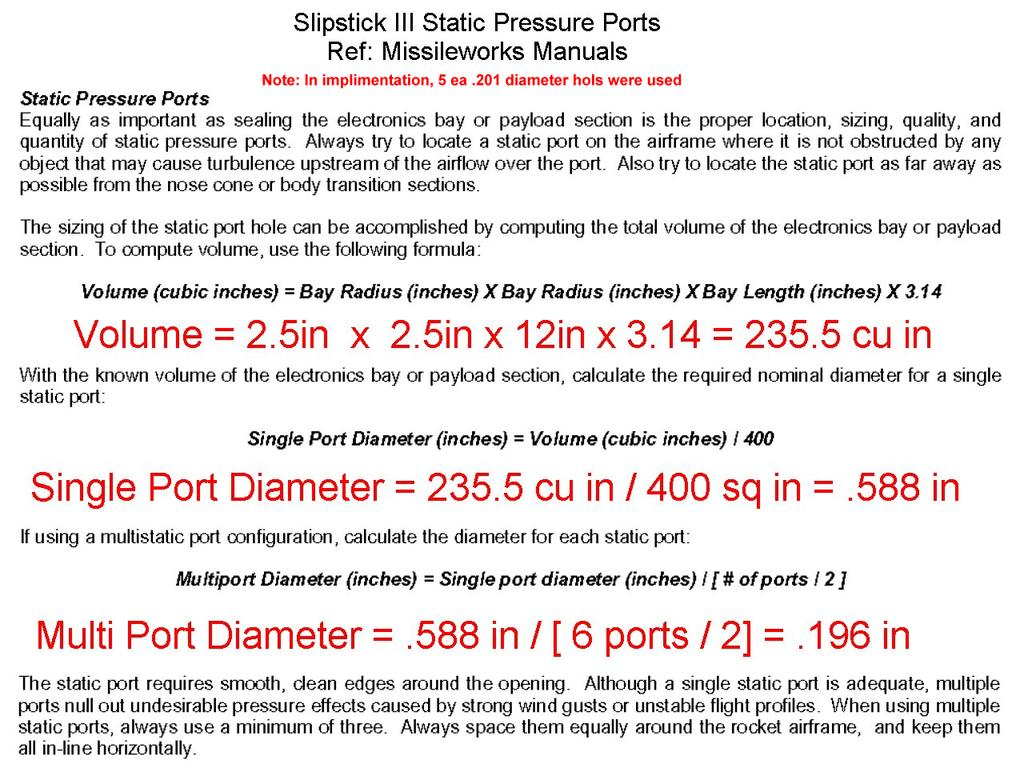
41

42

43

44

45
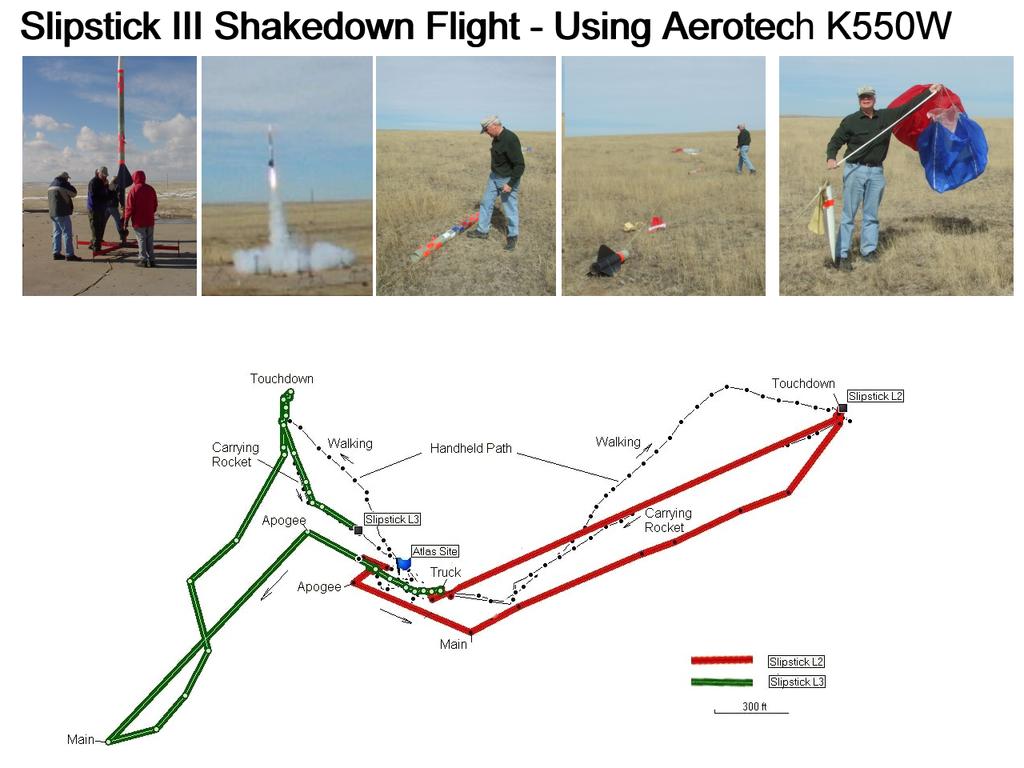
46

47

48

49
Pre-Flight Checklist for SLIPSTICK III
 Advanced Planning 1 Schedule a Check that waivers are available at the intended launch site and date. b Check weather forecast for wind and temperature conditions at the site. c Have TAP members approved
CRITICAL DESIGN REVIEW. University of South Florida Society of Aeronautics and Rocketry
 CRITICAL DESIGN REVIEW University of South Florida Society of Aeronautics and Rocketry 2017-2018 AGENDA 1. Launch Vehicle 2. Recovery 3. Testing 4. Subscale Vehicle 5. Payload 6. Educational Outreach 7.
FLIGHT READINESS REVIEW TEAM OPTICS
 FLIGHT READINESS REVIEW TEAM OPTICS LAUNCH VEHICLE AND PAYLOAD DESIGN AND DIMENSIONS Vehicle Diameter 4 Upper Airframe Length 40 Lower Airframe Length 46 Coupler Band Length 1.5 Coupler Length 12 Nose
Tripoli Rocketry Association Level 3 Certification Attempt
 Tripoli Rocketry Association Level 3 Certification Attempt Kevin O Classen 1101 Dutton Brook Road Goshen, VT 05733 (802) 247-4205 kevin@back2bed.com Doctor Fill Doctor Fill General Specifications Airframe:
Auburn University. Project Wall-Eagle FRR
 Auburn University Project Wall-Eagle FRR Rocket Design Rocket Model Mass Estimates Booster Section Mass(lb.) Estimated Upper Section Mass(lb.) Actual Component Mass(lb.) Estimated Mass(lb.) Actual Component
Presentation Outline. # Title # Title
 CDR Presentation 1 Presentation Outline # Title # Title 3 4 5 6 7 8 9 10 11 12 13 14 15 16 17 18 19 20 21 22 23 24 25 26 Team Introduction Vehicle Overview Vehicle Dimensions Upper Body Section Payload
Pegasus II. Tripoli Level 3 Project Documentation. Brian Wheeler
 Pegasus II Tripoli Level 3 Project Documentation Brian Wheeler Contents: A. Design Overview B. Booster Construction C. Electronics Bay (Mechanical) Construction D. Nose Cone Construction E. Recovery System
Jordan High School Rocketry Team. A Roll Stabilized Video Platform and Inflatable Location Device
 Jordan High School Rocketry Team A Roll Stabilized Video Platform and Inflatable Location Device Mission Success Criteria No damage done to any person or property. The recovery system deploys as expected.
CNY Rocket Team Challenge. Basics of Using RockSim 9 to Predict Altitude for the Central New York Rocket Team Challenge
 CNY Rocket Team Challenge Basics of Using RockSim 9 to Predict Altitude for the Central New York Rocket Team Challenge RockSim 9 Basics 2 Table of Contents A. Introduction.p. 3 B. Designing Your Rocket.p.
LEVEL 3 BUILD YELLOW BIRD. Dan Schwartz
 LEVEL 3 BUILD YELLOW BIRD Dan Schwartz This entire rocket is built using the same techniques I use for my nose cones, a central airframe tube for compression strength and rings of high compression styrofoam
Critical Design Review
 Critical Design Review University of Illinois at Urbana-Champaign NASA Student Launch 2017-2018 Illinois Space Society 1 Overview Illinois Space Society 2 Launch Vehicle Summary Javier Brown Illinois Space
CRITICAL DESIGN PRESENTATION
 CRITICAL DESIGN PRESENTATION UNIVERSITY OF SOUTH ALABAMA LAUNCH SOCIETY BILL BROWN, BEECHER FAUST, ROCKWELL GARRIDO, CARSON SCHAFF, MICHAEL WIESNETH, MATTHEW WOJCIECHOWSKI ADVISOR: CARLOS MONTALVO MENTOR:
Presentation Outline. # Title
 FRR Presentation 1 Presentation Outline # Title 3 4 5 6 7 8 9 10 11 12 13 14 15 16 17 18 19 20 21 22 23 24 Team Introduction Mission Summary Vehicle Overview Vehicle Dimensions Upper Body Section Elliptical
NASA USLI PRELIMINARY DESIGN REVIEW. University of California, Davis SpaceED Rockets Team
 NASA USLI 2012-13 PRELIMINARY DESIGN REVIEW University of California, Davis SpaceED Rockets Team OUTLINE School Information Launch Vehicle Summary Motor Selection Mission Performance and Predictions Structures
University Student Launch Initiative
 University Student Launch Initiative HARDING UNIVERSITY Flight Readiness Review March 31, 2008 Launch Vehicle Summary Size: 97.7 (2.5 meters long), 3.1 diameter Motor: Contrail Rockets 54mm J-234 Recovery
Skill Level 3 Average Skills Needed. Made In USA. Kit #04997 Skill Level 4. Zephyr Parts List
 Kit #04997 Skill Level 4 Made In USA Zephyr Parts List Item # Item Name Qty 10137 Engine Mount Tube (AT-38/11) 1 10218 Airframe Body Tube (AT-98/18) 4" Thick Wall 1 10219 Airframe Body Tube (AT-98/18)
NASA SL - NU FRONTIERS. PDR presentation to the NASA Student Launch Review Panel
 NASA SL - NU FRONTIERS PDR presentation to the NASA Student Launch Review Panel 1 Agenda Launch Vehicle Overview Nose Cone Section Payload Section Lower Avionic Bay Section Booster Section Motor Selection
Auburn University Student Launch. PDR Presentation November 16, 2015
 Auburn University Student Launch PDR Presentation November 16, 2015 Project Aquila Vehicle Dimensions Total Length of 69.125 inches Inner Diameter of 5 inches Outer Diameter of 5.25 inches Estimated mass
Illinois Space Society Flight Readiness Review. University of Illinois Urbana-Champaign NASA Student Launch March 30, 2016
 Illinois Space Society Flight Readiness Review University of Illinois Urbana-Champaign NASA Student Launch 2015-2016 March 30, 2016 Team Managers Project Manager: Ian Charter Structures and Recovery Manager:
Statement of Work Requirements Verification Table - Addendum
 Statement of Work Requirements Verification Table - Addendum Vehicle Requirements Requirement Success Criteria Verification 1.1 No specific design requirement exists for the altitude. The altitude is a
HPR Staging & Air Starting By Gary Stroick
 Complex Rocket Design Considerations HPR Staging & Air Starting By Gary Stroick 1. Tripoli Safety Code 2. Technical Considerations 3. Clusters/Air Starts 4. Staging 5. Summary 2 1. Complex High Power Rocket.
ADVANCED MODEL ROCKET
 Division of RCS Rocket Components, Inc. Assembly and Operation Instructions BEFORE YOU BEGIN: ADVANCED MODEL ROCKET COMPLETED INITIATOR ADVANCED MODEL ROCKET 19911-8091 Rev. 8/12/04 Study the illustrations
PRELIMINARY DESIGN REVIEW
 PRELIMINARY DESIGN REVIEW 1 1 Team Structure - Team Leader: Michael Blackwood NAR #101098L2 Certified - Safety Officer: Jay Nagy - Team Mentor: Art Upton NAR #26255L3 Certified - NAR Section: Jackson Model
ADVANCED MODEL ROCKET. Read And Follow All Instructions
 Division of RCS Rocket Components, Inc. Assembly and Operation Instructions BEFORE YOU BEGIN: ADVANCED MODEL ROCKET COMPLETED CHEETAH ADVANCED MODEL ROCKET 19916-3092 Rev. 8/12/04 Study the illustrations
ADVANCED MODEL ROCKET
 ADVANCED MODEL ROCKET Assembly and Operation Instructions Division of RCS Rocket Components, Inc. BEFORE YOU BEGIN: COMPLETED BARRACUDA ADVANCED MODEL ROCKET 19920-3092 Rev. 8/12/04 Study the illustrations
Project NOVA
 Project NOVA 2017-2018 Our Mission Design a Rocket Capable of: Apogee of 5280 ft Deploying an autonomous Rover Vehicle REILLY B. Vehicle Dimensions Total Length of 108 inches Inner Diameter of 6 inches
Flight Readiness Review
 Flight Readiness Review University of Illinois at Urbana-Champaign NASA Student Launch 2017-2018 Illinois Space Society 1 Overview Illinois Space Society 2 Launch Vehicle Summary Javier Brown Illinois
NASA - USLI Presentation 1/23/2013. University of Minnesota: USLI CDR 1
 NASA - USLI Presentation 1/23/2013 2013 USLI CDR 1 Final design Key features Final motor choice Flight profile Stability Mass Drift Parachute Kinetic Energy Staged recovery Payload Integration Interface
Preparing a Basic Rocket for Launch
 Preparing a Basic Rocket for Launch www.qldrocketry.com The following shows how to prepare an ESTES Patriarch for launch and the procedure for launching using the QRS launch controller. The motor we will
This Week. Next Week 4/7/15
 E80 Spring 2015 This Week! Transfer breadboard circuit to PC board.! Verify everything still works.! Get data logger working.! Pass off consists of: " Power PC board with data logger & start logging. "
COMPLETED MIRAGE ADVANCED MODEL ROCKET
 Division of RCS Rocket Components, Inc. BEFORE YOU BEGIN: Study the illustrations and sequence of assembly. The sequence of assembly is important. Review the parts list and become familiar with all parts
LaserHawk Flying Model Rocket Instructions Designed by Matt Steele
 VEHICLE DATA SHEET Physical Data North Coast Rocketry LaserHawk Flying Model Rocket Instructions Designed by Matt Steele Parameter Dimension Length Diameter 57 (145 cm) 2.64 (6.7 cm) Weight (w/o chute)
Presentation 3 Vehicle Systems - Phoenix
 Presentation 3 Vehicle Systems - Phoenix 1 Outline Structures Nosecone Body tubes Bulkheads Fins Tailcone Recovery System Layout Testing Propulsion Ox Tank Plumbing Injector Chamber Nozzle Testing Hydrostatic
COMPLETED SUMO LEVEL 1 MODEL ROCKET ADVANCED HIGH POWER MODEL ROCKET ASSEMBLY AND OPERATION INSTRUCTIONS BEFORE YOU BEGIN:
 COMPLETED SUMO LEVEL 1 MODEL ROCKET ADVANCED HIGH POWER MODEL ROCKET ASSEMBLY AND OPERATION INSTRUCTIONS BEFORE YOU BEGIN: Study the illustrations and sequence of assembly. The sequence of assembly is
NASA s Student Launch Initiative :
 NASA s Student Launch Initiative : Critical Design Review Payload: Fragile Material Protection 1 Agenda 1. Design Overview 2. Payload 3. Recovery 4. 5. I. Sub-Scale Predictions II. Sub-Scale Test III.
Critical Design Review Report
 Critical Design Review Report I) Summary of PDR report Team Name: The Rocket Men Mailing Address: Spring Grove Area High School 1490 Roth s Church Road Spring Grove, PA 17362 Mentor: Tom Aument NAR Number
Strap-on Booster Pods
 Strap-on Booster Pods Strap-On Booster Parts List Kit #17052 P/N Description Qty 10105 AT-24/12 Slotted (Laser Cut) Tube 2 10068 Engine Mount (AT-18/2.75) Tube 2 13029 CR 13/18 2 13031 CR 18/24 4 14352
Bumble Bee. Please read and understand all instructions before building!
 Bumble Bee The Bumble Bee kit contains all the parts necessary* to build a flying high power rocket: (1) Pre-slotted main airframe (1) Recovery tube (1) Nose cone (3) Fins (1) Piston ejection kit: (1)
Georgia Tech NASA Critical Design Review Teleconference Presented By: Georgia Tech Team ARES
 Georgia Tech NASA Critical Design Review Teleconference Presented By: Georgia Tech Team ARES 1 Agenda 1. Team Overview (1 Min) 2. 3. 4. 5. 6. 7. Changes Since Proposal (1 Min) Educational Outreach (1 Min)
MR-1. Please read and understand all instructions before building!
 MR-1 This kit contains all the parts necessary* to build a flying high power rocket: (1) Pre-slotted main airframe (1) Nose cone with strap (3) Fins (1) Transition (1) Airframe section 1 long (1) Piston
Rocket Design. Tripoli Minnesota Gary Stroick. February 2010
 Rocket Design Tripoli Minnesota Gary Stroick February 2010 Purpose Focus is on designing aerodynamically stable rockets not drag optimization nor construction techniques! Copyright 2010 by Gary Stroick
The University of Toledo
 The University of Toledo Project Kronos Preliminary Design Review 11/03/2017 University of Toledo UT Rocketry Club 2801 W Bancroft St. MS 105 Toledo, OH 43606 Contents 1 Summary of Proposal... 6 1.1 Team
Tacho Lycos 2017 NASA Student Launch Flight Readiness Review
 Tacho Lycos 2017 NASA Student Launch Flight Readiness Review High-Powered Rocketry Team 911 Oval Drive Raleigh NC, 27695 March 6, 2017 Table of Contents Table of Figures... 9 Table of Appendices... 11
FLYING MODEL ROCKET KIT INSTRUCTIONS KEEP FOR FUTURE REFERENCE. TEST-FIT ALL PARTS TOGETHER BEFORE APPLYING ANY GLUE!
 www.estesrockets.com ESTES INDUSTRIES 1295 H Street Penrose, CO 81240 PRINTED IN CHINA EST 1247/2053 FLYING MODEL ROCKET KIT INSTRUCTIONS KEEP FOR FUTURE REFERENCE. ASSEMBLY TIP: Read all instructions
NASA SL Critical Design Review
 NASA SL Critical Design Review University of Alabama in Huntsville 1 LAUNCH VEHICLE 2 Vehicle Summary Launch Vehicle Dimensions Fairing Diameter: 6 in. Body Tube Diameter: 4 in. Mass at lift off: 43.8
GIT LIT NASA STUDENT LAUNCH PRELIMINARY DESIGN REVIEW NOVEMBER 13TH, 2017
 GIT LIT 07-08 NASA STUDENT LAUNCH PRELIMINARY DESIGN REVIEW NOVEMBER TH, 07 AGENDA. Team Overview (5 Min). Educational Outreach ( Min). Safety ( Min) 4. Project Budget ( Min) 5. Launch Vehicle (0 min)
First Revision No. 9-NFPA [ Chapter 2 ]
![First Revision No. 9-NFPA [ Chapter 2 ]](/thumbs/76/73617213.jpg "First Revision No. 9-NFPA [ Chapter 2 ]") 1 of 14 12/30/2015 11:56 AM First Revision No. 9-NFPA 1127-2015 [ Chapter 2 ] Chapter 2 Referenced Publications 2.1 General. The documents or portions thereof listed in this chapter are referenced within
1 of 14 12/30/2015 11:56 AM First Revision No. 9-NFPA 1127-2015 [ Chapter 2 ] Chapter 2 Referenced Publications 2.1 General. The documents or portions thereof listed in this chapter are referenced within
Tacho Lycos 2017 NASA Student Launch Critical Design Review
 Tacho Lycos 2017 NASA Student Launch Critical Design Review High-Powered Rocketry Team 911 Oval Drive Raleigh NC, 27695 January 13, 2017 Table of Contents Table of Figures:... 8 Table of Appendices:...
Close Proximity Recovery System
 CPR-MAX Close Proximity Recovery System Tired of the long walks associated with recovering high altitude rockets? So were we! That s why we developed the Close Proximity Recovery System (CPR). CPR uses
Skill Level 3 Average Skills Needed. Skill Level 3. Ibis Parts List
 Kit #05152 Skill Level 3 Made In USA Ibis Parts List Item # Item Name Qty 10076 AT- 18/3.5" LC - Engine Mount Tube 1 10123 AT- 33/6.5" LC - Body Tube 1 10124 AT- 33/18" LC - Body Tube 1 13029 CR- 13/18
User Manual and Instructions Model RRC² - Rocket Recovery Controller Revision C
 User Manual and Instructions Model RRC² - Rocket Recovery Controller Revision C System Overview The RRC 2 Rocket Recovery Controller provides two stage barometrically controlled deployment of rocket recovery
Overview. Mission Overview Payload and Subsystems Rocket and Subsystems Management
 MIT ROCKET TEAM Overview Mission Overview Payload and Subsystems Rocket and Subsystems Management Purpose and Mission Statement Our Mission: Use a rocket to rapidly deploy a UAV capable of completing search
COMPLETED ASTROBEE D ADVANCED MODEL ROCKET
 Division of RCS Rocket Components, Inc. BEFORE YOU BEGIN: ADVANCED MODEL ROCKET Assembly and Operation Instructions Study the illustrations and sequence of assembly. The sequence of assembly is important.
University of Illinois at Urbana-Champaign Illinois Space Society Student Launch Preliminary Design Review November 3, 2017
 University of Illinois at Urbana-Champaign Illinois Space Society Student Launch 2017-2018 Preliminary Design Review November 3, 2017 Illinois Space Society 104 S. Wright Street Room 18C Urbana, Illinois
NUMAV. AIAA at Northeastern University
 NUMAV AIAA at Northeastern University Team Officials Andrew Buggee, President, Northeastern AIAA chapter Dr. Andrew Goldstone, Faculty Advisor John Hume, Safety Officer Rob DeHate, Team Mentor Team Roster
COMPLETED ASTROBEE D ADVANCED MODEL ROCKET ADVANCED MODEL ROCKET
 19915-1092 Rev.6/99 BEFORE YOU BEGIN: ADVANCED MODEL ROCKET Assembly and Operation Instructions COMPLETED ASTROBEE D ADVANCED MODEL ROCKET Study the illustrations and sequence of assembly. The sequence
SpaceLoft XL Sub-Orbital Launch Vehicle
 SpaceLoft XL Sub-Orbital Launch Vehicle The SpaceLoft XL is UP Aerospace s workhorse space launch vehicle -- ideal for significant-size payloads and multiple, simultaneous-customer operations. SpaceLoft
MASSACHUSETTS INSTITUTE OF TECHNOLOGY Department of Aeronautics and Astronautics
 MASSACHUSETTS INSTITUTE OF TECHNOLOGY Department of Aeronautics and Astronautics 16.00 Introduction to Aerospace and Design Problem Set #4 Issued: February 28, 2002 Due: March 19, 2002 ROCKET PERFORMANCE
Northwest Indian College Space Center USLI Critical Design Review
 2012-2013 Northwest Indian College Space Center USLI Critical Design Review Table of Contents, Tables, and Figures I.0 CDR Report Summary... 1 I.1 Team Summary... 1 I.2 Launch Vehicle Summary... 1 I.2a
Tripoli Level 2 Test Questions - Technical
 Tripoli Level 2 Test Questions - Technical 1. Which of Newton's Laws best describes the behavior of a rocket motor? a. Newton's First Law: Every body continues in its state of rest or of uniform motion
Public Missiles, Ltd.
 Public Missiles, Ltd. Co-Pilot Dual-Deployment Recovery Altimeter SYSTEM OVERVIEW...2 SPECIFICATIONS...2 HANDLING PRECAUTIONS...2 OPERATIONAL OVERVIEW...3 FIGURE 1 - GENERAL COMPONENT LAYOUT OF THE PML
Electronic Deployment
 Electronic Deployment and a little bit of recovery too! By: Gerald Meux, Jr. NAR and TRA Level 3 1-3-11 8/28/2014 Electronic Deployment - Gerald Meux, Jr. 1 Table of Contents 8/28/2014 Electronic Deployment
Wichita State Launch Project K.I.S.S.
 Wichita State Launch Project K.I.S.S. Benjamin Russell Jublain Wohler Mohamed Moustafa Tarun Bandemagala Outline 1. 2. 3. 4. 5. 6. 7. Introduction Vehicle Overview Mission Predictions Payload Design Requirement
NASA USLI Flight Readiness Review (FRR) Rensselaer Rocket Society (RRS)
 Rensselaer Rocket Society (RRS)") 2016-2017 NASA USLI Flight Readiness Review (FRR) Rensselaer Rocket Society (RRS) Rensselaer Polytechnic Institute 110 8th St Troy, NY 12180 Project Name: Andromeda Task 3.3: Roll Induction and Counter
2016-2017 NASA USLI Flight Readiness Review (FRR) Rensselaer Rocket Society (RRS) Rensselaer Polytechnic Institute 110 8th St Troy, NY 12180 Project Name: Andromeda Task 3.3: Roll Induction and Counter
Flight Readiness Review Addendum: Full-Scale Re-Flight. Roll Induction and Counter Roll NASA University Student Launch.
 Flight Readiness Review Addendum: Full-Scale Re-Flight Roll Induction and Counter Roll 2016-2017 NASA University Student Launch 27 March 2017 Propulsion Research Center, 301 Sparkman Dr. NW, Huntsville
EL DORADO COUNTY REGIONAL FIRE PROTECTION STANDARD
 EL DORADO COUNTY REGIONAL FIRE PROTECTION STANDARD STANDARD #H-004 EFFECTIVE 06-30-09 REVISED 7-20-17 PURPOSE This standard is intended to provide the permit requirements and safety directives for the
University of Notre Dame
 University of Notre Dame 2016-2017 Notre Dame Rocketry Team Critical Design Review NASA Student Launch Competition Roll Control and Fragile Object Protection Payloads Submitted January 13, 2017 365 Fitzpatrick
Student Launch. Enclosed: Preliminary Design Review. Submitted by: Rocket Team Project Lead: David Eilken
 University of Evansville Student Launch Enclosed: Preliminary Design Review Submitted by: 2016 2017 Rocket Team Project Lead: David Eilken Submission Date: November 04, 2016 Payload: Fragile Material Protection
Team Air Mail Preliminary Design Review
 Team Air Mail Preliminary Design Review 2014-2015 Space Grant Midwest High-Power Rocket Competition UAH Space Hardware Club Huntsville, AL Top: Will Hill, Davis Hunter, Beth Dutour, Bradley Henderson,
Information Pack for Mid Power Rockets
 Information Pack for Mid Power Rockets www.qldrocketry.com Table of Contents 1. Introduction... 2 2. Terminology... 3 3. Rocket Flight Phases... 4 4. Igniters... 5 5. Motors... 6 5.1 Key Components...
Critical Design Review Report NASA Student Launch Florida International University American Society of Mechanical Engineers (FIU-ASME)
") Critical Design Review Report 2014-2015 NASA Student Launch Florida International University American Society of Mechanical Engineers (FIU-ASME) Florida International University Engineering Center College
Critical Design Review Report 2014-2015 NASA Student Launch Florida International University American Society of Mechanical Engineers (FIU-ASME) Florida International University Engineering Center College
University Student Launch Initiative
 University Student Launch Initiative HARDING UNIVERSITY Critical Design Review February 4, 2008 The Team Dr. Edmond Wilson Brett Keller Team Official Project Leader, Safety Officer Professor of Chemistry
Critical Design Review
 AIAA Orange County Section Student Launch Initiative 2011-2012 Critical Design Review Rocket Deployment of a Bendable Wing Micro-UAV for Data Collection Submitted by: AIAA Orange County Section NASA Student
The University of Toledo
 The University of Toledo Project Cairo Preliminary Design Review 10/08/2016 University of Toledo UT Rocketry Club 2801 W Bancroft St. MS 105 Toledo, OH 43606 Contents 1 Summary of Preliminary Design Review...
What s Happening in Our NAR. April, 2012 Trip Barber NAR 4322 NAR President
 What s Happening in Our NAR April, 2012 Trip Barber NAR 4322 NAR President How Are We Doing? Our membership levels are at an all-time high Around 5300 thanks to concerted NAR-wide efforts including the
First Nations Launch Rocket Competition 2016
 First Nations Launch Rocket Competition 2016 Competition Date April 21-22, 2016 Carthage College Kenosha, WI April 23, 2016 Richard Bong Recreational Park Kansasville, WI Meet the Team Wisconsin Space
1:6 BLACK BRANT II. c o s m o d r o m e r o c k e t r y
 c o s m o d r o m e r o c k e t r y 1:6 BLACK BRANT II This kit is capable of use with high thrust motors. It is therefore strongly recommended that epoxy be used throughout the construction of this kit.
Range Safety Officer Operations Manual
 Range Safety Officer Operations Manual Presented by the Blue Mountain Rocketeers National Association of Rocketry Section # 615 Instructor: Tim Quigg; NAR 62887 SR / L2 / TSO Section Advisor Blue Mountain
PROJECT AQUILA 211 ENGINEERING DRIVE AUBURN, AL POST LAUNCH ASSESSMENT REVIEW
 PROJECT AQUILA 211 ENGINEERING DRIVE AUBURN, AL 36849 POST LAUNCH ASSESSMENT REVIEW APRIL 29, 2016 Motor Specifications The team originally planned to use an Aerotech L-1520T motor and attempted four full
Flight Readiness Review March 16, Agenda. California State Polytechnic University, Pomona W. Temple Ave, Pomona, CA 91768
 Flight Readiness Review March 16, 2018 Agenda California State Polytechnic University, Pomona 3801 W. Temple Ave, Pomona, CA 91768 Agenda 1.0 Changes made Since CDR 2.0 Launch Vehicle Criteria 3.0 Mission
SUPPLIES In addition to the parts included in the kit you will also need: ASSEMBLY TIP FLYING MODEL ROCKET KIT INSTRUCTIONS EST 2055/1246
 FLYING MODEL ROCKET KIT INSTRUCTIONS www.estesrockets.com Estes Industries 1295 H Street Penrose, CO 81240 PRINTED IN CHINA MOUNT Keep for Future Reference EST 2055/1246 ASSEMBLY TIP Read all instructions
Modified shock-cord mount and cables (cables are shown pushed into motor mount here)
") Building the Ariel Builder: Ray Wilkinson This is Ray Wilkinson's own rocket, but will mostly reside at UH, and will be used for display purposes as well as being flown. It's built from a kit made by PML
Building the Ariel Builder: Ray Wilkinson This is Ray Wilkinson's own rocket, but will mostly reside at UH, and will be used for display purposes as well as being flown. It's built from a kit made by PML
Critical Design Review
 Harding University University Student Launch Initiative Team Critical Design Review January 29, 2007 The Flying Bison Sarah Christensen Project Leader Dr. Ed Wilson Faculty Supervisor Dr. James Mackey
PML RECOVERY COMPONENTS FAQ
 PML RECOVERY COMPONENTS FAQ Parachutes Construction/Design 10/22/03 PML chutes are made by a real parachute company, are not just hobby parachutes. All are multi-panel chutes, not a flat disc with shroud
Preliminary Design Review. Cyclone Student Launch Initiative
 Preliminary Design Review Cyclone Student Launch Initiative Overview Team Overview Mission Statement Vehicle Overview Avionics Overview Safety Overview Payload Overview Requirements Compliance Plan Team
CONTRAIL ROCKETS RESEARCH AND DEVELOPMENT FROM: LDRS 25 O MOTOR FAILURE ANALYSIS SUBJECT: DATE: 8/11/2006
 FROM: SUBJECT: CONTRAIL ROCKETS RESEARCH AND DEVELOPMENT LDRS 25 O MOTOR FAILURE ANALYSIS DATE: 8/11/2006 On July 1 st, 2006 at LDRS 25 in Amarillo, Texas Contrail Rockets suffered a motor failure. The
Post Launch Assessment Review
 AIAA Orange County Section Student Launch Initiative 2011-2012 Post Launch Assessment Review Rocket Deployment of a Bendable Wing Micro-UAV for Data Collection Submitted by: AIAA Orange County Section
Preliminary Design Review. California State University, Long Beach USLI November 13th, 2017
 Preliminary Design Review California State University, Long Beach USLI November 13th, 2017 System Overview Launch Vehicle Dimensions Total Length 108in Airframe OD 6.17in. ID 6.00in. Couplers OD 5.998in.
UC Berkeley Space Technologies and Rocketry Preliminary Design Review Presentation. Access Control: CalSTAR Public Access
 UC Berkeley Space Technologies and Rocketry Preliminary Design Review Presentation Access Control: CalSTAR Public Access Agenda Airframe Propulsion Payload Recovery Safety Outreach Project Plan Airframe
Northwest Indian College Space Center USLI Post Launch Assessment Review
 Northwest Indian College Space Center USLI Post Launch Assessment Review 2012-2013 Table of Contents I. Team Summary... 1 Team Name: Northwest Indian College RPGs... 1 II. Launch Vehicle Summary... 1
PARACHUTE RECOVERY FUN TO BUILD AND FLY USES STANDARD ENGINES TWO STAGE CAN ALSO BE FLOWN AS SINGLE STAGE BALSA FINS & NOSE CONE
 1. Materials. I will use only lightweight, non-metal parts for the nose, body, and fins of my rocket. 2. Motors. I will use only certified, commercially-made model rocket motors, and will not tamper with
PARACHUTE INSTALLATION MANUAL BRS SP P & M Aviation Quik & Quik GT 450 Trike Aircraft. Abstract
 Ballistic Recovery Systems, Inc. 300 Airport Rd South Saint Paul MN 55075-3551 USA www.brsparachutes.com Voice: 651-457-7491 FAX: 651-457-8651 PARACHUTE INSTALLATION MANUAL BRS-6 1050 SP P & M Aviation
Florida A & M University. Flight Readiness Review. 11/19/2010 Preliminary Design Review
 Florida A & M University Flight Readiness Review 11/19/2010 Preliminary Design Review 1 Overview Team Summary ~~~~~~~~~~~~~~~~~~~~~~~~~~~~~~ ~~~~~~~~ Vehicle Criteria ~~~~~~~~~~~~~~~~~~~~~~~~~~~~~~ ~~~~~~~~
Sky Ripper Systems. 38mm hybrid rocket motor kit.
 Sky Ripper Systems 38mm hybrid rocket motor kit. Thank you for buying a Sky Ripper Systems hybrid rocket motor. This motor hardware has been designed to give you years of flying enjoyment with the proper
PARACHUTE INSTALLATION MANUAL BRS 1350 HS FLIGHT DESIGN GmbH, CTLS. Abstract
 Ballistic Recovery Systems, Inc. 380 Airport Rd South Saint Paul MN 55075-3551 USA www.brsparachutes.com Voice: 651-457-7491 FAX: 651-457-8651 PARACHUTE INSTALLATION MANUAL BRS 1350 HS FLIGHT DESIGN GmbH,
LIMITATION OF LIABILITY 100% SATISFACTION GUARANTEE JOIN THE NAR! About. Semroc Astronautics Corporation
 1. Materials. I will use only lightweight, non-metal parts for the nose, body, and fins of my rocket. 2. Motors. I will use only certified, commercially-made model rocket motors, and will not tamper with
t!z ESFE~ PARTS AND SUPPLIES ROCKET ASSEMBLY 1. FLYING MODEL ROCKET #2054 .~. 1111l~i '~~
 t!z ESFE~ ESTES INDUSTRIES 1295 H Street Penrose, CO 81240 USA ASSEMBLY TIP BETA LAUNCH FLYING MODEL ROCKET #2054 VEHICLETM Read all instructions before beginning work on your model. Make sure you have
AMWPro75 Motor Adapter Instructions
 AMWPro75 Motor Adapter Instructions This document is an addendum to the Pro75 instructions. It explains how to load Pro75 reload kits into AMW75 snap ring style motor casings using the AMWPro75 motor adapter.
Illinois Space Society University of Illinois Urbana Champaign Student Launch Maxi-MAV Preliminary Design Review November 5, 2014
 Illinois Space Society University of Illinois Urbana Champaign Student Launch 2014-2015 Maxi-MAV Preliminary Design Review November 5, 2014 Illinois Space Society 104 S. Wright Street Room 321D Urbana,
Notre Dame Rocketry Team. Flight Readiness Review March 8, :00 PM CST
 Notre Dame Rocketry Team Flight Readiness Review March 8, 2018 2:00 PM CST Contents Overview Vehicle Design Recovery Subsystem Experimental Payloads Deployable Rover Payload Air Braking System Safety and