ATTENZIONE WARNING ATTENTION ATENCION ATENÇÃO ACHTUNG ПРЕДУПРЕЖДЕНИЕ
|
|
|
- Madeleine Parrish
- 6 years ago
- Views:
Transcription
1 Ins stalla ation n, ope eration a and m ntena main ance e H ndb Han book k Pulle er Mod del: ARS A S70 0
2 ATTEZIOE Per motivi di sicurezza durante il trasporto la macchina è fornita senza olio idraulico e senza carburante. el presente fascicolo troverete informazioni sulle caratteristiche e le quantità richieste. In caso di dubbio consultare la TESMEC. WARIG The machine is supplied without hydraulic oil and fuel during transport for precautionary measures. Please refer to this manual for all information regarding the characteristics and quantities required. Should you have any doubt, please get in touch with TESMEC. ATTETIO Pour mesures de sécurité, pendant le transport la machine est livrée sans huile hydraulique et sans carburant. Référez-vous à ce manuel pour renseignements nécessaires sur les caractéristiques et quantités. En cas de doute veuillez contacter TESMEC. ATECIO Por motivos de seguridad la máquina se transporta sin aceite hidráulico y sin combustible. En el presente fascículo encontrarán informaciones acerca de las características y de las cantidades requeridas. En caso de dudas, consultar a TESMEC. ATEÇÃO Por razões de segurança durante o transporte, a máquina é fornecida sem óleo hidráulico e combustível. o presente folheto poderão encontrar as informações sobre as características a as quantidades requeridas. Caso tenham alguma dúvida, rogamos-lhes pôr-se em contacto com a TESMEC. ACHTUG Aus Sicherheitsgründen während des Transportes, wird die Maschine ohne Öl und Kraftstoff geliefert. Im vorliegenden Gebrauchsanweisungsheft werden Sie Informationen über die Eigenschaften und Mengen des Öls finden. Wenn Sie im Zweifel sind, fragen Sie TESMEC um Rat. ПРЕДУПРЕЖДЕНИЕ Из соображений безопасности, при поставке машина транспортируется без рабочей жидкости в гидравлической системе и топлива. Пожалуйста, пользуйтесь настоящим руководством для получения любых сведений, касающихся характеристик и заправочных емкостей. В случае каких-либо сомнений, пожалуйста, свяжитесь с компанией ТЕСМЕК Grassobbio (Bg) via Zanica, 7/O Endine Gaiano (Bg) via Pertegalli Tel / 035 / Tel / 035 / Telefax 0039 / 035 / Telefax 0039 / 035 / info@tesmec.it info@tesmec.it
3 PULLER Model: ARS70 PULLER Model: ARS70 Serial number Manufacturing year 20 Working order 4835 USE AD MAITEACE ISTRUCTIOS
4 PULLER Model: ARS70. GEERAL IDEX Page. GEERAL IDEX 2. GEERAL DATA AD PRESCRIPTIOS 3 2. MAUFACTURER COMMUICATIOS WITH THE MAUFACTURER TYPOLOGY AD USIG FIELD PERFORMACES TECHICAL CHARACTERISTICS ACOUSTIC EMISSIO GEERAL IFORMATIO FOR THE MACHIE USE GEERAL PRESCRIPTIOS FOR THE OPERATOR CHARGED OF THE MACHIE USE GEERAL PRESCRIPTIOS FOR THE OPERATOR CHARGED OF THE MACHIE MAITEACE KOWLEDGE AD CARE OF THE ISTRUCTIO MAUAL 5 2. CODITIO OF USE TEMPERATURE LIMITS FOR HYDRAULIC OIL USE OT ALLOWED RESPOSIBILITY APPLIED ORMS 7 3. TRASPORT AD POSITIOIG ISTRUCTIOS 8 3. MACHIE LIFTIG TRASPORT TYPOLOGIES AD PACKAGE UPACKIG ASSEMBLIG OPERATIOS TRASPORT O TRAILER POSITIOIG AD ACHORIG 9 4. ISTRUCTIO FOR USE 4. PRESCRIPTIOS FOR THE OPERATOR 4.2 COTROLS 4.3 PRELIMIARY OPERATIOS 4.4 MACHIE SET-UP 4.5 ELECTROIC MULTI-FUCTIOS DISPLAY PAGES MACHIE START-UP PULL COTROL PULL LIMITIG DEVICE SETTIG PULL PROGRAMMIG DEVICE SETTIG REEL LOADIG AD PUTTIG THE REEL WIDER I WORKIG POSITIO REMOVIG THE REEL COECTIO BETWEE MACHIE AD HYDRAULIC HEAD OF THE REEL ELEVATOR OR REEL WIDER 5 4. MACHIE USE MACHIE STOP ROPE LOCKIG CLAMP (OPTIOAL) REMOTE COTROL (OPTIOAL) POITS TO REMEMBER EXTERAL REEL WIDER COECTIO (OPTIOAL) 8 5. ISTRUCTIO FOR USE COECTED MACHIES 9 5. GEERAL ASPECTS MACHIES SET-UP COECTED MACHIES OPERATIOS PULL COTROL SETTIG PULL LIMITIG DEVICE SETTIG PULL PROGRAMMIG DEVICE SETTIG USIG OF ELECTROIC SPEED SYCHROIZER DEVICE (OPTIOAL) ROPE LOCKIG CLAMP (OPTIOAL) 22 Manual: MI-ARS GB Date: Author: A. Oscar Page: of 3
5 PULLER Model: ARS ALARM CODITIO WHE USIG COECTED MACHIES STRIGIG LEGTH ERROR SWITCH O THE MACHIE WITH COTROL OT I EUTRAL EMERGECY STOP CA-BUS DIS-COECTIO BETWEE THE MACHIES ROPE-CLAMP POSITIO GEAR-BOX LOW-PULL POSITIO COECTIO MACHIE SELECTOR COMPOET FAULT SAFETY CODITIOS SAFETY DEVICES EMERGECY STOP DEVICE PERIODIC OPERATIOS RESIDUAL RISKS MAITEACE GEERAL PRESCRIPTIOS LEVELS COTROL TYRES IFLATIO PRESSURE SUGGESTED LUBRICATS EDOTHERMIC EGIE MAITEACE HYDRAULIC CIRCUIT MAITEACE REDUCTIO GEAR STATIOARY BRAKES MAITEACE RADIATORS MAITEACE GREASIG OTHER PERIODIC OPERATIOS SUMMARY TABLE FOR ORDIARY MAITEACE HOW TO DISABLE THE MACHIE TRASPORT EXTEDED SERVICE STOP STRIPPIG ECLOSED DOCUMETS 3 9. TABLES SYSTEMS OTHER DOCUMETS 3 Manual: MI-ARS GB Date: Author: A. Oscar Page: 2 of 3
6 PULLER Model: ARS70 2. GEERAL DATA AD PRESCRIPTIOS 2. MAUFACTURER Via Zanica, 7/O GRASSOBBIO BG - ITALY tel. (+39) fax (+39) service-stringing@tesmec.it parts-stringing@tesmec.it info@tesmec.it TESMEC S.p.A. Via Pertegalli, EDIE GAIAO BG - ITALY tel. (+39) fax (+39) service-stringing@tesmec.it parts-stringing@tesmec.it info@tesmec.it 2.2 COMMUICATIOS WITH THE MAUFACTURER For any information related to the machine (use, maintenance, spare parts) always state Model, Serial umber, Manufacturing Year and Order. These data can be found in the machine-identifying table. 2.3 TYPOLOGY AD USIG FIELD The machine mod. ARS700 is suitable for the drive of a steel rope with a max. diameter of 24 mm. The bull-wheels grooves are made of heat-treated steel, allow the passage of joints with a max. diameter of 60 mm. The power transmission to the large groove bull-wheels is transmitted through a closed hydraulic circuit with a variable delivery pump and fixed displacement motor, with the possibility to change continuously the speed in both rotating directions. A hydraulic vacuum brake stops automatically the two large groove bull-wheels should the work be interrupted and a damage in the hydraulic circuit occur. The machine is equipped with a heat exchanger to cool the hydraulic oil; a thermostat regulates the functioning of the electric motor that controls the fan. The puller is equipped with a hydraulically-controlled reel winder with automatic level winder, rear stabiliser, front jack with hydraulic control and connections for anchoring to the ground; the frame can be mounted on a rigid axle for towing at 30 km/hour and hand wheel brake. 2.4 PERFORMACES Max. pull: Max. pull speed: Max. speed: Pull at max. speed: 80 k 2,5 km/h 5 km/h 80 k ATTETIO: the use of ropes with smaller diameter will reduce the pulling capacity of the machine, in accordance with the breaking load of the rope. Performances are referred to the machine without optional, at sea level and at 20 C. Manual: MI-ARS GB Date: Author: A. Oscar Page: 3 of 3
7 PULLER Model: ARS TECHICAL CHARACTERISTICS Bull-wheels nominal diameter: 600 mm Max. rope diameter: 24 mm Diesel engine: 209 kw rpm Electric system: 24 V Transmission: closed hydraulic circuit with hydraulic oil cooling Safety brake: negative and self-acting type Dynamometer: hydraulic with set point and automatic control of maximum pull Axle: rigid type with mechanical parking brake for towing at max speed of 30 km/h Dimensions: length mm width mm height mm Mass: 5700 kg 2.6 ACOUSTIC EMISSIO Level of continuous sound pressure to the operator seat (UI 9432) Lep = 85 db(a) 2.7 GEERAL IFORMATIO FOR THE MACHIE USE a. Only employed and qualified operators must use the machine. Qualified operators is intended to be the person who has received a qualified training from the using Company or, as alternative, from the manufacturer. b. Machine must be used only for the work it was designed for. c. Machine cannot be used with non-authorised personnel on the working site. d. For safety reasons, during transport machine comes without hydraulic oil and fuel. Characteristics and required quantities are listed in the present manual. e. For any doubt concerning use, functioning, maintenance or everything else, contact the After-sales Service of the manufacturer. 2.8 GEERAL PRESCRIPTIOS FOR THE OPERATOR CHARGED OF THE MACHIE USE a. Operator has to know safety directives for accident prevention in force in the machine using country, for a correct use of the same. b. The operator in charge with the installation and maintenance of the machine must use suitable clothes to the working site and to the situation where he finds himself; in particular he must avoid the use of very large clothes, chains, bracelets, rings or whatever can get entangled with moving parts. c. The operator has to use the necessary protecting devices (i.e. gloves, boots, helmet, etc.). It is compulsory the use of personal protecting devices for hearing. d. The operator must not carry out on his own initiative operations or interventions that are not up to him. e. The operator must carefully follow danger and/or prohibition prescriptions contained in the instruction manual or indicated on the machine. f. The working area of the operator has to be cleaned from possible oil or liquids wastes and free of materials or equipment that may be considered as on obstacle for the operator work. g. The operator must absolutely avoid the direct inhalation of the exhaust gas of the endothermic engine. Manual: MI-ARS GB Date: Author: A. Oscar Page: 4 of 3
8 PULLER Model: ARS GEERAL PRESCRIPTIOS FOR THE OPERATOR CHARGED OF THE MACHIE MAITEACE a. It is absolutely forbidden to carry out any work of maintenance, adjustment or setting on units while stringing (except for the operations indicated in the present manual). b. Before carrying out any maintenance operations, stop the energy feeding (except for the cases indicated in the present manual) and wait till the cooling of the elements subjected to heating. c. All the maintenance operations of the machine must be carried out with machine on a level surface and not under load. d. Authorised and trained personnel must do all the maintenance operations, ordinary and not ordinary. Trained personnel are intended to be the person who has received a qualified training from the using Company or, as alternative, from the manufacturer. e. The operator in charge with the machine maintenance must use suitable clothes to the working site and to the situation where he finds himself; in particular he must avoid the use of very large clothes, chains, bracelets, rings or whatever can get entangled with moving parts. f. The operator has to use the necessary protecting devices (i.e. gloves, boots, helmet, etc.). g. All the maintenance operations, ordinary and not ordinary, must be effectuated respecting the prescriptions included in the present manual or following technical indications written by the manufacturer. The non-respect of the prescribed restrains relieves the manufacturer from any responsibility causing also the loss of warranty. 2.0 KOWLEDGE AD CARE OF THE ISTRUCTIO MAUAL a. The information contained in the instruction manual applies to all the operators charged with the use and/or the maintenance of the machine. b. The instruction manual is not a training manual. c. Before using the machine the chief of the job site and the operator must read the instruction manual. d. The chief of the job site is obliged to inform all the operators about the instructions contained in the manual. e. The user must carefully follow the instructions listed in the present manual. f. Before using the machine, the operator must be able to use it and has to exactly know the positions and the operations of all the controls. g. The chief of the job site must verify that the instructions contained in the manual are applied. h. The instruction manual must be kept, in order to be consulted, for all the life of the machine and also when it is given to another user. i. The instruction manual must be kept in a sheltered and dry place. ATTETIO: present manual belongs exclusively to the manufacturer. The reproduction, event partial, of the text is forbidden. 2. CODITIO OF USE a. Temperature: from -0 C to +40 C. b. Relevant moisture: from 30% to 90% ± 5%. c. Weather conditions: any (in line with working conditions). d. atural and/or artificial lighting of the working site. Manual: MI-ARS GB Date: Author: A. Oscar Page: 5 of 3
9 PULLER Model: ARS TEMPERATURE LIMITS FOR HYDRAULIC OIL When using the machine, always remember to respect the following temperature limits that can be reached with hydraulic oil as function of the working condition. TEMPERATURE LIMITS FOR HYDRAULIC OIL ( C) Working condition Hydraulic oil viscosity VG 22 VG 32 VG 46 VG 68 Minimum temperature running in neutral position Minimum temperature running in full load Maximum temperature running in full load Maximum temperature running in neutral position For additional information concerning the hydraulic oil, see chapter "Maintenance" and the attached comparative table of the oils used on the machine. 2.3 USE OT ALLOWED The machine must not be used: a. for lifting persons and/or goods b. in grounds on which the machine can not be positioned and anchored in a proper way c. in areas with brushwood or other materials presence that can be easily set on fire d. in closed/unventilated sites or, however, not sufficiently airy (tunnel or similar) e. in sites with presence of gas that can be easily set on fire or explosives f. in sites with presence of explosive materials g. on aircraft, crafts, floating platforms and similar h. for structure demolition, shafts felling or similar i. for pulling flexible elements that can be highly lengthening, which allow elastic power accumulation j. with ropes or joints having a bigger diameter than the one specified in present manual k. when engine is off and bull-wheels are moving l. with inhibited and broken safety devices installed on the machine m. when winding on the bull-wheels ropes and/or conductors having a smaller diameter as a succession of ropes and/or conductors having a bigger diameter n. for handling trucks or other moving equipment. PROHIBITIO: is not allowed to install on board radio equipments. These could create electronic equipment malfunctions, putting the personnel at serious risk. 2.4 RESPOSIBILITY The use of the machine for scopes different from those foreseen on paragraph 2.3 (Typology and using field), even if not well described in this manual, has to be considered extremely dangerous and then forbidden. The non-respect of the prescribed restrains causes a situation of improper use for technical and persons safety purposes and relieve the manufacturer from any responsibility, civil or penal, in case of accidents to persons or damages to things, causing the loss of warranty. The manufacturer responsibility declines even when one of the following situations happens: a. for the consequences caused by tampering and/or modifications carried out without the manufacturer s written acceptance (in this case the operator becomes the manufacturer with relevant obligations and responsibilities, both civil and penal) b. for the use of not original spare parts c. or bad maintenance d. for the use with disconnected safety devices e. for the connection to machine and/or plans not produced and not directly authorised by the manufacturer in a written acceptance. Manual: MI-ARS GB Date: Author: A. Oscar Page: 6 of 3
10 PULLER Model: ARS APPLIED ORMS Machine is manufactured in conformity with the following norm: 2006/42/CE orm referring to the laws of the machines. 2004/08/CE orm referring to the laws of the electromagnetic compatibility. Manual: MI-ARS GB Date: Author: A. Oscar Page: 7 of 3
11 PULLER Model: ARS70 3. TRASPORT AD POSITIOIG ISTRUCTIOS 3. MACHIE LIFTIG For the machine lifting use only devices as overhead travelling cranes or lift trucks, with a capacity equal to the mass to be lifted. The instruments used for the machine lifting (ropes, cables, hooks, etc.) have to be exactly dimensioned as compared to the mass to be lifted and have to be connected to the proper elements foreseen on the machine (table 2, pos. 5). During machine lifting operations, the presence of persons on the machine is strictly forbidden. DAGER: the non-respect of the above mentioned conditions may cause dangerous situations as well as damages to the machine with the consequent decline of any warranty condition. 3.2 TRASPORT TYPOLOGIES AD PACKAGE Transport by land by truck The machine comes without all the liquids that can be set on fire and protected in the most exposed and delicate parts by means of cardboard and/or plywood and/or polyethylene extensible film. To fix the machine on the platform of the transporting unit, use nailed wedges and/or metal brackets and/or tie rods. Transport by sea in wooden cases or container The machine comes without all the liquids that can be set on fire; metal parts are protected with waterproof wax. To fix the machine on the package, use nailed wedges and/or metal brackets and/or tie rods. At the inside, the wooden case foreseen a protection with tarpaper. Materials usually used for the package are: wooden nails and/or steel screws cardboard and/or paper polyethylene extensible film adhesive tape. 3.3 UPACKIG When receiving the machine verify the integrity of the package; advise immediately the manufacturer and the person in charge of the transport (even with photos) when possible damages due to transport or tampering with removal, even partial, of the content happen. Verify if the supplied material corresponds to the ordered one; immediately advise the manufacturer if there are some discrepancies. In case of transportation on wooden case, take away, in sequence, the upper cover and lateral panels, before removing the machine. During unpacking operations, avoid any shock to the structure or to the machine units, in order to avoid any damage to the machine itself. ATTETIO: the elimination of packaging materials must be effectuated in conformity with the norms in force in the relevant country. Manual: MI-ARS GB Date: Author: A. Oscar Page: 8 of 3
12 PULLER Model: ARS ASSEMBLIG OPERATIOS Mount the tyres in the suitable holes. 3.5 TRASPORT O TRAILER Machine is not suitable for road towing. Possible displacements on trailer in the working site must be carried out by a connection to the towing unit by means of the towing eye on the drawbar (table, pos. ) and in the respect of the speed limits of the axle. The used towing unit must be homologated for towing trailers with mass and dimensions as per the described machine. Before transporting lift the rear stabilisers (table, pos. 0) and the front share (table, pos. 2) acting on the lever (table 3, pos. 26) (OTE: this operation must be done with started motor). Moreover, the reel winder must be put in transport position (table, pos. 6) acting on the lever (table 3, pos. 24) (OTE: this operation must be done with started motor). Check the inflation pressure of tyres (7 bars). During machine transport operations, nobody must stay on the machine itself. ATTETIO: dangerous situations during towing if the tyre inflation pressure and the speed limit are not respected may happen. When transporting on truck or trailer, verify if the machine has been fixed on the platform with nailed wedges and/or metal brackets and/or tie rods. 3.6 POSITIOIG AD ACHORIG Positioning and anchoring of the machine have to be carried out only by trained personnel, verifying if the ground grants the foreseen stability, support and anchoring. The machine has to be placed in a distance from the first pylon or trestle for the rope passage (or conductor) included between 2 and 4 times the height h of the pylon itself (see diagram here below). It is possible to use the machine at a distance from the pole included between and 2 times the height of the pole itself. In this case, the anchorage described thereafter must be over dimensioned of 25% compared to the reported data and some moorings must be provided on the front side of the machine. PROHIBITIO: when the distance between the machine and the pole is lower than the height of the pole itself, the machine use is not possible. Manual: MI-ARS GB Date: Author: A. Oscar Page: 9 of 3
13 PULLER Model: ARS70 Machine anchoring sequence is the following: a. keep the wheel brakes of the machine disengaged. b. position the rear stabilisers as much as possible near the ground compatibly with the locking holes. c. adjust the front plough with the manipulator (table 3, pos. 26) so that to let the rear stabilisers rest on the ground; this way it is possible to discharge the tyres. d. anchor the machine to the ground using adequate ropes and turnbuckles, connecting the ears (table 2, pos. 3), located at the rear of the machine, to the anchoring stakes. The ropes must form an angle with the direction of the pull as shown on table 2, to allow the machine to react to possible transverse forces as well. e. put the reel winder in working position as per point 4.5. Wind the pull rope onto the bull-wheel, as shown on table 2, and fasten it to the reel. Close the max. relief valve (table 3, pos. 3) till on the manometer (table 3, pos. 4) can be read a pressure of about 60 bars sufficient to keep the rope tightened. IMPORTAT: before starting stringing operations, we suggest to test the pull, reaching the max. value expected for the operations, in order to check the carried out anchoring and the machine settling. It is better to have the rear anchoring slightly released so that the machine can freely settle. f. put the anchoring ropes under tension using the suitable turnbuckles (if necessary, anchor the machine also in the front). g. block the machine brakes acting on the handle brake wheel (table 2, pos. 5). ATTETIO: the non-respect of the foreseen anchoring operations may cause dangerous situations during machine use. Around the machine must be a free space of at least 2-m to make easier the operations of use, adjustment, maintenance, etc. Be sure that around the radiators (endothermic motor, hydraulic oil) cooling air can freely circulate. Otherwise overheating situations with damage for the installed components may happen. DAGER: machine has not a proper grounding device; for the system machine-ropeconductor in the job site must foreseen a grounding device on the towing rope or on the conductors. Manual: MI-ARS GB Date: Author: A. Oscar Page: 0 of 3

14 PULLER Model: ARS70 4. ISTRUCTIO FOR USE 4. PRESCRIPTIOS FOR THE OPERATOR PROHIBITIO: it is forbidden to walk or stop in front or backward the machine and/or under the towing rope due to a constant residual risk of crushing in case of a possible giving in of the rope or of the anchoring. Daily, before starting the work, check: a. if the protection and safety devices are activated and functioning according to the lamps b. if the connections with the power unit are in good conditions c. if the machine liquids levels are in conformity with the indications in maintenance chapter d. if the anchoring conditions are in conformity with the indications of present manual. 4.2 COTROLS Position and meaning of the elements on the control board are described on table 3 enclosed. 4.3 PRELIMIARY OPERATIOS a. Set the reel winder as indicated at point 4.8. b. Wind the rope as indicated on table and 2 making sure that it is well placed on the grooves. The free end must be inserted in the suitable roller ways and connected to the reel as per indications at point 4.8. To connect the rope on the reel it is necessary to open the valve (table 3, pos. 3) till a pressure lower than 20 bars can be read on the manometer (table 3, pos. 4). It grants that the reel doesn t rotate during connection operations. c. After connecting the rope, increase the pressure till 50 bars so that the reel, when rotating, put under tension the rope section between itself and the bull-wheels. DAGER: please pay attention to the risk to be squeezed during the operations above described. 4.4 MACHIE SET-UP Before the use, the machine must be set in stand-alone using mode, operating on the control panel (table 3). a. insert and turn the ignition key (table 3, pos. 3) in "" position b. wait up to the multifunction display switch on (table 3, pos. ) c. on the electronic multifunction display press the ( ) key d. on the screen page MACHIE ID: set the number by using the up ( ) or down ( ) key press the return key ( ) to save the settings OTE: in case of stand-alone using mode the ID of the machine must always be set at Manual: MI-ARS GB Date: Author: A. Oscar Page: of 3


15 PULLER Model: ARS70 When the machine is used in stand-alone configuration the two plug connectors must be closed with the related caps 4.5 ELECTROIC MULTI-FUCTIOS DISPLAY PAGES The electronic multifunction display shows 4 working pages:. METER COUTER & SPEED PAGE This page shows the speed and the meter counter speed of capstan nr. meter counter of capstan nr. r.p.m diesel engine Hydraulic oil temperature Manual: MI-ARS GB Date: Author: A. Oscar Page: 2 of 3


 or down ( ) key Manual: MI-ARS70-60-0-GB Date: 25.")
16 PULLER Model: ARS70 2. RPM & DIESEL EGIE PAGE This page shows the rpm of the diesel engine in the center and 4 percentage check icons on the edges: diesel engine water cooling temperature hydraulic oil temperature diesel engine oil pressure diesel engine fuel level 3. DIESEL EGIE DATA PAGE This page shows 4 percentage check icons of diesel engine data: diesel engine torque output accelerator opening diesel engine diesel engine fuel consumption diesel engine fuel level 4. HOUR COUTER PAGE This page shows the working hour of the diesel engine in the center and 4 percentage check icons on the edges: diesel engine rpm hydraulic oil temperature diesel engine torque output diesel engine fuel level Switch from one page to the other one by using the up ( ) or down ( ) key Manual: MI-ARS GB Date: Author: A. Oscar Page: 3 of 3
17 PULLER Model: ARS MACHIE START-UP a. Operate from the main control panel (table 3). b. Position to centre the control lever of the variable delivery pump (table 3, pos. 9). c. Turn the ignition key (table 3, pos. 3) and start-up the Diesel engine. d. Regulate the rpm with the accelerator (table 3, pos. 4). e. Verify that the pressure indicated on the feeding manometer (table 3, pos. ) is higher than 25 bar with minimum rpm; on the contrary stop the machine. ATTETIO: during the cold starting sequence, let disconnected the fan of the hydraulic oil radiator, turn the selector leftwards (table 3, pos. 5) and let idle the machine for about 5-20 minutes with the Diesel engine at medium rpm. ATTETIO: when starting a cold machine, after preheating the hydraulic oil as previously described, begin stringing operations limiting the maximum working performances for at least the first 5 minutes, that means to keep the Diesel rpm at about 500 rpm and don t exceed the 30% of the maximum stringing speed. ATTETIO: during the stoppages, let the diesel engine run with the fan of the hydraulic... oil radiator engaged by positioning leftwards the selector. 4.7 PULL COTROL The machine is equipped with two pull control devices for the control of the max. pull value on the line:. PULL LIMITIG DEVICE that stops the machine when reaching the max. pull 2. PULL PROGRAMMIG DEVICE that stops only the bull-wheels rotation keeping the diesel engine turned on when reaching the max. pull PULL LIMITIG DEVICE SETTIG Completely turn rightwards the potentiometer (table 3, pos. 6). With the suitable pawl, connected to the dynamometer (table 3, pos.2), move the red arrow in correspondence of the max. pulling value that has not to be exceeded. When the pre-set pull value is reached, the machine stops automatically and the diesel engine turns off while the negative brakes automatically connect with the consequent stop of the bull-wheels rotation. When the pull value is exceeded the warning light (table 3, pos. 7) on the control panel switches on PULL PROGRAMMIG DEVICE SETTIG ATTETIO: THE OPERATIOS TO SET THE PULL MUST BE CARRIED OUT WITH STARTED DIESEL EGIE BUT WITH STOPPED MACHIE. Start the diesel engine and set the engine at about 600 rpm. Move the selector (table 3, pos. 8) on position (rightwards). Gently move towards (downwards) the lever (table 3, pos. 9). Turn the potentiometer (table 3, pos. 6) till on the dynamometer ring nut (table 3, pos. 2) can be read the pull value that must not be exceeded (puller mode) or the desired pull value for working (tensioner mode). ATTETIO: the red arrow of the pull limiting device (paragraph 4.7.) has to be positioned at a higher value than the one pre-set with the PULL PROGRAMMIG DEVICE to avoid the machine stop. Manual: MI-ARS GB Date: Author: A. Oscar Page: 4 of 3
18 PULLER Model: ARS70 Gently move the lever (table 3, pos. 9) to central position (neutral position). Re-place the selector (table 3, pos. 8) on position (leftwards). Once reached the max. pre-set pull, the bull-wheels stop keeping the pull (puller mode) or release the conductor to the pre-set pull (tensioner mode). ATTETIO: after finishing the above mentioned operations and beginning stringing operations, it is important not to touch the potentiometer (table 3, pos. 6). In fact, should the potentiometer be rotated while the machine is stringing, this operation cancels the previous carried out calibration and the systems set on the new values congruent with new position of the potentiometer. Then, avoid this operation, using it only in emergency situations. ATTETIO: before starting the work, check if the selector (table 3, pos. 8) is on position. It is forbidden to move the selector (table 3, pos. 8) during working operations because extremely dangerous situations because the machine immediately stops may happen. 4.8 REEL LOADIG AD PUTTIG THE REEL WIDER I WORKIG POSITIO The following steps must be carried out when the engine is running: a. act on the lever (table 3, pos. 24) so that the reel winder is in a position that enables the reel (table, pos. 4) to be loaded. b. insert the reel in the reel carrier (table 4, pos. 8), making sure to have firmly closed the reel by the suitable ring nut (table 4, pos. 3). c. put the reel carrier behind the reel winder, aligning the axis of the reel with the vertical of the reel winder supports. d. slightly lift the reel winder using the lever (table 3, pos. 24), so that the supports (table 4, pos. ) fasten the reel carrier shaft (table 4, pos. 2). ow insert the reel fixing nut (table 4, pos. 8) and the safety pin (table 4, pos. 5). Lower the dragging tooth of the reel (table 4, pos. 4), mounted on the gear, so that it can be inserted in one spoke of the reel carrier; to place the dragging tooth, release it by means of the safety pin (table 4, pos. 7). e. act on the lever (table 3, pos. 24) to lift the reel winder beyond the working position to make easier the winding and the locking of the rope on the reel. For locking the rope on the reel, act as follows: insert the rope end in the suitable slot on the reel place a clamp on the rope to avoid that it unthreads. f. move the reel winder by the lever (table 3, pos. 24) on working position (table, pos. 9). 4.9 REMOVIG THE REEL a. Completely unscrew the locking pin (table 4, pos. 8). b. Unlock the bracket (table 4, pos. 5). c. Disconnect the entrainer (table 4, pos. 4). d. Lower the reel winder operating on the lever (table 3, pos. 24). 4.0 COECTIO BETWEE MACHIE AD HYDRAULIC HEAD OF THE REEL ELEVATOR OR REEL WIDER Each hydraulic head (or each reel winder) has a connecting kit consisting of two pipes. Each pipe has to be connected to the proper rapid coupler (table 9, pos and ) making care to connect them properly (otherwise the installation will not work). Manual: MI-ARS GB Date: Author: A. Oscar Page: 5 of 3
19 PULLER Model: ARS70 ATTETIO: it is important that, before connecting the rapid couplers, the operator has checked their cleanliness as the introduction of dirt into the hydraulic circuit can create very serious damages. ATTETIO: the rapid couplers must be connected before putting the circuit under pressure. 4. MACHIE USE a. Position the selector (table 3, pos. 3) on "Automatic" position (turned leftwards selector), so that to automatically start the rotation of the reel winder using the control lever of the bull-wheels (table 3, pos. 9). b. Set the selector (table 3, pos. 8) on position (turned leftwards selector). ATTETIO: when the selector (table 3, pos. 8) is on position (turned rightwards selector) the hydraulic circuit is under pressure but the bull-wheels remain stopped. c. Act on the accelerator (table 3, pos. 4) until the engine has reached the desired rpm (2600-rpm max.). d. The valve (table 3, pos. 3) regulates the counter-pull of the reel winder and the corresponding pressure can be seen on the manometer (table 3, pos. 4). The pressure value is set at about 50 bar when the reel has a few wound rope turns and, with the increasing of the number of rope winding on the reel, the pressure has to be increased up to a max. value of bars. For the releasing manoeuvre, the pressure must be of 40 bars. e. Gently move the lever (table 3, pos. 9) on position (downwards). At this point the machine is ready to work and automatically it will start to recover if the pull in the rope is lower than the puller s pull or it will start to release while braking if the pull in the rope is higher than the puller s pull. After setting the pull with the PULL PROGRAMMIG DEVICE function (paragraph 4.7.2), the machine stops or starts automatically following the movements of the counteracting machine. The conductor pulling value can be read on the dynamometer (table 3, pos. 2). f. To stop the motion of the bull-wheels, gently re-move the lever (table 3, pos. 9) to central position. This operation automatically inserts the negative brakes that stop the bull-wheels. OTE: when moving the lever to central position (table 3, pos. 9) the negative brakes insert automatically. ATTETIO: quickly move the lever (table 3, pos. 9) from the working position to the central neutral position is dangerous for the negative safety brakes discs that have to bear a heavy load when operated. g. To release the rope move on position (upwards) the control lever (tab. 3, pos. 9). Manual: MI-ARS GB Date: Author: A. Oscar Page: 6 of 3
. c. completely open the valve (table 3, pos. 3).")
20 PULLER Model: ARS MACHIE STOP To stop the machine act as follows: a. move the lever (table 3, pos. 9) on central position. b. set the engine rpm to the minimum value acting on the accelerator (table 3, pos. 4). c. completely open the valve (table 3, pos. 3). d. turn off the engine turning the key (table 3, pos. 3). OTE: when towing the machine, the rear stabilisers have to be completely lifted (table, pos. 0). The reel winder as to be on transport position (table, pos. 9). 4.3 ROPE LOCKIG CLAMP (OPTIOAL) The rope locking clamp allows blocking the rope end towards the reel winder and therefore the operations for removing the reel are speed up. To engage the rope locking clamp, turn the selector (table 3, pos.27) on position (leftwards - blocked no light) and keep them in position for a few second to allow the complete closing of the clamp. To dis-engage the rope locking clamp, turn the selector (table 3, pos.27) on position (rightwards free green light) and keep them in position for a few second to allow the complete opening of the clamp. 4.4 REMOTE COTROL (OPTIOAL) The remote control includes: accelerator bull-wheels control lever emergency stop push button. Once the remote control has been connected to the control panel, by means of the suitable socket, the accelerator and the bull-wheels control on the control panel are deactivated. To activate them, disconnect the remote control. The emergency stop push buttons are active both on the control panel and on the remote control. ATTETIO: the remote control does not replace the control panel, but it is just a device, which allows to temporarily moving away from the machine in order to better control the line or the machine. Manual: MI-ARS GB Date: Author: A. Oscar Page: 7 of 3
21 PULLER Model: ARS POITS TO REMEMBER a. The pressure of the feeding circuit (table 3, pos. ) must be higher than 25 bar: otherwise, the stationary brakes will be damaged. b. Adjust the pull of the reel elevators with hydraulic head (table 3, pos. 3) at minimum indispensable value: otherwise, the hydraulic oil will be uselessly heated and dangerous counter pulls may arise. c. In hot climates, during stoppages, let the Diesel engine running with the radiator fan (table 3, pos. 5) engaged at maximum speed. d. Before beginning the works, check the levels. e. Respect the temperature limits for the hydraulic oil as indicated at paragraph 2.2. f. After an emergency intervention of the negative safety brake, verify the condition of the brake discs. g. During the removing phases of the reel, remember to unscrew the locking pin (table 4, pos. 8), to unlock the bracket (table 4, pos. 5) and to disconnect the entrainer (table 4, pos. 4) before lowering the reel. h. It is strictly forbidden to wind on the bull-wheels ropes and/or conductors with a lower diameter in succession of ropes and conductors with a larger diameter. 4.6 EXTERAL REEL WIDER COECTIO (OPTIOAL) Connect the connecting hoses to the rapid couplers (table 0, pos. -2). ATTETIO: the connecting and disconnecting operations of the rapid couplers have to be effectuated with stopped machine and with the valve (table 0, pos. 3) completely open. If there is pressure in the hydraulic circuit, it is not possible to carry out any connecting and disconnecting manoeuvre of the connecting hoses. The valve (table 0, pos. 3) regulates the tension of the reel winder and the corresponding pressure can be seen on the manometer (table 0, pos. 4). Manual: MI-ARS GB Date: Author: A. Oscar Page: 8 of 3
.")

22 PULLER Model: ARS70 5. ISTRUCTIO FOR USE COECTED MACHIES 5. GEERAL ASPECTS This machines could be equipped with an electronic connection package as an optional device. This device allow to use multiple machines connected between them, controlled and operated by a single operator for the main working parameters (basically speed, pull, diesel engine rpm). Is possible to connect a maximum 2 machines between them, with the possibility to work with 2 independent ropes configurations. Tesmec suggest to use this configuration device on machine working at the puller station, to allow to recover multiple ropes or conductors with the same speed. The machines must be numbered with ID number (see next chapter) from to the number of total connected machines starting from right to left, looking at the machines from the back (reel-winder position). The last machine, positioned on the right, is the master machine. See table 0 as example. The machines must be connected through a special connecting cable; the un-used plugs on the first and on the last machine (right and left) must always be closed with the related caps. To grant the continuous connection of the machines, a special protection device must be provided for the connection cables, to avoid accidental disconnection of the communication between the machines. Manual: MI-ARS GB Date: Author: A. Oscar Page: 9 of 3


23 PULLER Model: ARS70 It is necessary to provide a correct grounding of each machine, to avoid trouble at the electronic devices. For this reason each machine is equipped with a special grounding device that must be connected prior to switch on each machine. The correct grounding configuration is realized with a grounding stakes (see table 0) to be placed on the ground in front at the machine, and a connecting ground cable, that must connect all the ground stakes between them. Prior to operate the set-up of the machines, check that: The machines are connected through the special connecting cable The ground devices are installed and connected The gear-box configuration is HIGH-PULL in each machine (optional) Manual: MI-ARS GB Date: Author: A. Oscar Page: 20 of 3

 or down ( ) key e.")
24 PULLER Model: ARS MACHIES SET-UP Before the use the machine must be set in connected mode by assign to each machine the correct ID number, starting from left to right, as described in the previous chapter. a. insert and turn the ignition key (table 3, pos. 3) in position b. wait up to the multifunction display switch on (table 3, pos. ) c. on the electronic multifunction display press the ( ) key d. on the screen page MACHIE ID: set the correct number by using the up ( ) or down ( ) key e. press the return key ( ) to save the settings OTE: the ID of the machines must be set from to the total number of connected machines starting from left to right (looking at the machines from the back reel-winder position) e. set each machine in connection configuration, except the final one, by turning rightwards the selector (table 3, pos. 5). 5.3 COECTED MACHIES OPERATIOS When using connected machines, the following controls effect on all machines when operated from the master machine: Speed control (joy-stick) Pull-adjusting control (potentiometer) egative brake open close selector Diesel engine accelerator Rope-clamp selector When using connected machines, the following controls must be operated on each single machine: Reel-winder working pressure Reset of meter counter Pull limiting device in the dynamometers Main front plough position 5.4 PULL COTROL SETTIG 5.4. PULL LIMITIG DEVICE SETTIG With the suitable pawl, connected to the dynamometers (table 3, pos. 2), move the red arrow in correspondence of the max. pulling value that has not to be exceeded. The pre-set value must be the same for all the machines connected, and must be set on each single machine. Manual: MI-ARS GB Date: Author: A. Oscar Page: 2 of 3

25 PULLER Model: ARS PULL PROGRAMMIG DEVICE SETTIG The setting must be operated at the circuit of the last connected machine and will effect on all the machines. The operation sequence is the same described on the stand alone using mode chapter USIG OF ELECTROIC SPEED SYCHROIZER DEVICE (OPTIOAL) The machine could be provided with an electronic speed synchronizer device as a optional package; to activate operate on the selector (table 3, pos. 6) (rightwards) on the master machine. This device allow to have the same recovering speed of each connected machines. 5.6 ROPE LOCKIG CLAMP (OPTIOAL) When the machine are connected the proper selector on the master machine operate on all the clamps of the connected machines. To engage the rope locking clamp, turn the proper selector on the master machine (table 3, pos.27) on position (leftwards - blocked no light) and keep it in position for a few second to allow the complete closing of the clamp. To dis-engage the rope locking clamp, turn the proper selector on the master machine (table 3, pos.27) on position (rightwards free green light) and keep it in position for a few second to allow the complete opening of the clamp. 5.7 ALARM CODITIO WHE USIG COECTED MACHIES When using connected machines some situation generate alarm condition with switch on of the alarm light on the main control panel of the machine where the alarm is generated STRIGIG LEGTH ERROR When the electronic speed synchronizer system is active, an eventual difference of stringing length on the independent ropes larger than a default value programmed (generally 6 m) generate an error and the stringing operations stops on all the connected machines. To reset the alarm move the joy-stick to neutral on the master machine and dis-engaged the speed synchronized selector; check the cause of the alarm on the line (ex. Operation of the pull programming system and arrest of one rope line) before to re-start SWITCH O THE MACHIE WITH COTROL OT I EUTRAL When the machine is switched on with joy-stick not in neutral position, an alarm is generated and the capstans don t move. Manual: MI-ARS GB Date: Author: A. Oscar Page: 22 of 3
26 PULLER Model: ARS EMERGECY STOP Pressing the emergency stop in one of the connected machines generate the stop of the engine of the single machine where the stop has been activated and the stop of the movement of all the remaining connected machines, where the diesel engine remain switched on. To reset the alarm move the joy-stick to neutral on the master machine before to dis-engaged the emergency stop on the machine in emergency situation CA-BUS DIS-COECTIO BETWEE THE MACHIES In case the connection cables between the machine may disconnect (ex. removing plugs, accidental cutting of one cable, ), the stringing operations stops on all the connected machines. To reset the alarm move the joy-stick to neutral on the master machine and check the cause of the fault ROPE-CLAMP POSITIO In case one of the rope-clamp is not completely open (electrical switch pressed and green light switched on), none of the ropes can moves on all the connected machines GEAR-BOX LOW-PULL POSITIO In case one of the gear-boxes is in a low-pull position, (electrical switch pressed and green light switched on), none of the ropes can moves on all the connected machines COECTIO MACHIE SELECTOR In case one of the connection machine selector is changed to off (leftwards) while connected machine are running, all the machines will stop COMPOET FAULT In case of fault in one of the joy-stick & potentiometers component, the system switches on default parameters with alarm indicator on control panel (L or L2). In case of fault on pull adjusting solenoid valve the system only shows alarm indicator on control panel (L or L2). Manual: MI-ARS GB Date: Author: A. Oscar Page: 23 of 3
27 PULLER Model: ARS70 6. SAFETY CODITIOS 6. SAFETY DEVICES Machine has been equipped with the following safety devices:. load-limiting device with automatically stop of the engine once the max. pre-set load value has been exceeded 2. mechanical negative safety brake for movement stop in case of lack of hydraulic pressure 3. timing case and protections on moving parts, where technologically possible. DAGER: it is absolutely forbidden the use of the machine without protecting timing cases or with damaged/disconnected safety devices. ATTETIO: after a serious emergency use of the negative safety brake, check the wear condition of the discs and the efficiency of the brake itself; if necessary, replace the brake discs before re-using the machine. 6.2 EMERGECY STOP DEVICE The machine is equipped with an emergency stop device (table 3, pos. 0) that directly acts on the Diesel engine. The power generator locking causes the intervention of the negative safety brakes and, consequently, the complete machine stop. ATTETIO: use the emergency stop device OLY in danger situations for the operators' safety. OTE: for restoring the machine it is necessary to unlock the emergency device with a deliberate manoeuvre (turn for a quarter, in clockwise direction, the push button). The emergency stop device for stopping the machine while working must only be used in emergencies. 6.3 PERIODIC OPERATIOS Daily, before starting the work, the operator has to verify the functionality of the machine safety devices. ATTETIO: do not modify for any reason safety devices of the machine because the manufacturer declines any responsibility as consequence of the non-functioning of the same. 6.4 RESIDUAL RISKS In the machine there are still the following residual risks:. Sudden break of the rope. The break of the rope causes sudden movements of the machine and of the rope or conductor connected to the machine. To reduce to min. the risks the operator has to: check the rope and replace it as soon as appear some defects or wear signs respect the working positions indicated in the manual. 2. Sudden break of the anchoring stakes. The sudden break of the anchoring stakes causes the machine instability and sudden movements of the same. To reduce to min. the risks the operator has to: periodically check the anchoring stakes and replace them as soon as appear some defects or wear signs Manual: MI-ARS GB Date: Author: A. Oscar Page: 24 of 3
28 PULLER Model: ARS70 follow the anchoring indications described in the present manual respect the working positions indicated in the manual. 3. Entangling or dragging of the accessible rotating units. It is not technologically possible to foreseen covering in correspondence of some rotating units (i.e. winding of the rope or of the conductor on the bull-wheels or on the driving gears), due to an excessive restriction of the machine functionality and operative functions. To reduce to min. the risks the operator has to: avoid any possible contact with the machine rotating units except for the control devices follow the anchoring indications described in the present manual respect the prescriptions indicated in the present manual concerning wearing and the necessary safety devices. 4. Limbs crushing during loading or removal of the reel and during rope loading. These operations have a large risk margin due to the use of mechanical parts to be moved. To reduce to min. the risks the operator has to: know the directives for accident prevention and apply them. 5. Electrostatic discharges. The machine has not a proper grounding device for this reason during stringing operation it is possible to have dangerous electrostatics discharges on ropes and conductors. To reduce to min. the risks the operator has to: know the directives for accident prevention and apply them check if the job site has a suitable grounding device for the machine-rope-conductors system. 6. Inhalation of the endothermic engine exhausting gas. The machine discharge exhausting gas of the endothermic engine combustion. To reduce to min. the risks the operator has to: respect the working positions indicated in the manual respect the indications of attention and prohibition indicated in the present manual if necessary, use safety devices for the respiratory tracts. 7. Control lever that can be locked in working position. For functional reasons and comfort in the use the control lever does not foresees the return to zero when released. Anyway, the machine is equipped with two security devices that prevent the creation of dangerous situations: electric limiting device of the pull on the dynamometer, which stops the power station when the stated value is reached, and load pre-setting device, which maintains the settled pull adjusting automatically the speed of the work. To reduce to min. the risks the operator has to: put the electric limiting device of the pull on a value just superior to the of the regulating valves of the pull (see par. 4.6 and 4.7) plan the desired pull as described in the manual (see par. 4.6 and 4.7). Manual: MI-ARS GB Date: Author: A. Oscar Page: 25 of 3
29 PULLER Model: ARS70 7. MAITEACE 7. GEERAL PRESCRIPTIOS ATTETIO: possible repairs not carried out by the manufacturer and not allowed by a written authorisation relieve the manufacturer for any responsibility in case of accidents to persons or damages to things and/or to the machine, causing also the loss of warranty. 7.2 LEVELS COTROL For safety reasons, during the transport machine comes without hydraulic oil and fuel. Fill the levels as per the following table: Quantity a. Hydraulic oil level (table 2, pos. 4) 50 l b. Engine oil level (see enclosed engine booklet) c. Reduction gear oil level (table 2, pos. 9) 3.7 l d. Reel winder brake oil level (table 4, pos. 0) 0. l e. Fuel level (table 3, pos. 2) 30 l ATTETIO: the non-respect of the correct levels causes serious damages to the installed components. DAGER: do not ingest hydraulic liquids, fuels and cooling liquids because injurious to health and potentially lethal. 7.3 TYRES IFLATIO PRESSURE Tyres inflation pressure has to be 7 bars. ATTETIO: the non-respect of tyres inflation pressure causes dangerous situations during transport operations. 7.4 SUGGESTED LUBRICATS The manufacturer tests the machine with the following oils and lubricants: a. hydraulic circuit: AGIP OSO 46 (ISO HM 46) b. mechanical reduction gear: AGIP BLASIA 220 (ISO CKC 220) c. stationary brake reel winder: AGIP OSO 46 (ISO HM 46). Possible different trademarks must be chosen based on the enclosed table "SUGGESTED LUBRICATS". It is possible to use different trademarks but with same characteristics and ISO specifications. When using oil with characteristics and ISO specifications different from the ones declared during test, completely empty out the hydraulic circuit. ATTETIO: the use of lubricants not in conformity with the technical specifications indicated in the present manual seriously damages the machine components and, consequently, the warranty conditions are not valid. Manual: MI-ARS GB Date: Author: A. Oscar Page: 26 of 3
30 PULLER Model: ARS EDOTHERMIC EGIE MAITEACE For the specific maintenance of the engine, see the enclosed use and maintenance booklet. For filling the fuel, use the filling cap on the tank (table, pos. 5). For filling the radiator liquid, use the filling cap on the radiator (table 2, pos. 2). DAGER: to fill the fuel and the radiator liquid, turn off the engine; before carrying out any operation let the engine be cooled. 7.6 HYDRAULIC CIRCUIT MAITEACE a. Change the hydraulic oil after 500 working hours and, thereafter, every 500 hours (or in any case every year). b. To discharge the exhaust hydraulic oil, use the suitable tap in the tank (table 2, pos. 7). DAGER: let the hydraulic oil be completely cooled before removing it and always use the suitable safety wears (gloves, etc.). ATTETIO: the discharge of the exhaust oils has to be effectuated in conformity with the laws in force in the relevant country. c. Fill the oil in the tank by means of the suitable filler (table 2, pos. 8). ATTETIO: make maximum care when filling to make sure no foreign matter, which could cause irreparable damages to the circuit s components, enters along with the oil; if possible filter the oil with a 0 μm filter. d. Replace the filter cartridge (table 2, pos. 4) after 500 working hours and, thereafter, every 500 hours (or every year at least). e. Daily check the clogging of the oil filters. If necessary replace the cartridges taking care of the following filtering grade: intake filters for overfeeding pump: 0 µ (nominal values) intake services filter (plunged in the hydraulic oil tank): 90 µ (nominal values) For further maintenance operations of installed hydraulic components (pumps and motors), refer to the enclosed documentation. 7.7 REDUCTIO GEAR STATIOARY BRAKES MAITEACE a. Change the oil of the reduction gear, of the stationary brake of the reel winder and of the coupler after 50 working hours and, thereafter, every 500 hours (or every year at least). b. To discharge the exhaust oil of the reduction gear and of the stationary brake, use the suitable caps on the lower part of the casing. DAGER: let the hydraulic oil be completely cooled before removing it and always use the suitable safety wears (gloves, etc.). ATTETIO: the discharge of the exhaust oils has to be effectuated in conformity with the laws in force in the relevant country. c. Fill the oil of the reduction gear and of the stationary brake by means of the suitable caps on the upper part of the casing. ATTETIO: make maximum care when filling to make sure no foreign matter, which could cause irreparable damages to the circuit s components, enters along with the oil. For further maintenance operations of installed mechanic components (reduction gear, negative brakes), refer to the enclosed documentation. Manual: MI-ARS GB Date: Author: A. Oscar Page: 27 of 3
31 PULLER Model: ARS RADIATORS MAITEACE At least once a year, or more in case of use in dusty places, is foreseen a blowhole with compressed air of the radiant mass of the radiators. ATTETIO: in order to make this operation the one in charge of maintenance, besides wearing all the protection devices already shown in this manual, must also wear a device for protecting respiratory organs. 7.9 GREASIG Grease 2-3 times per day the crown gear of the bull-wheels using the suitable greaser (table 2, pos. 2). Weekly grease all the other parts subjected to rotation or translation and that not foreseen a forced lubrication or an automatic greasing. Use IP ATHESIA GR2 (ISO XBCEA 2) grease or equivalent of another trademark based on the enclosed "SUGGESTED LUBRICATS" table. 7.0 OTHER PERIODIC OPERATIOS When cleaning the machine, avoid direct jets of water or steam on the components of the electric system of the machine and on the control panel. For the other periodic operations, refer to the summary table for the ordinary maintenance (see next paragraph). Manual: MI-ARS GB Date: Author: A. Oscar Page: 28 of 3
32 PULLER Model: ARS70 7. SUMMARY TABLE FOR ORDIARY MAITEACE In this card are listed main operation of periodic maintenance and relevant intervals. Part Object Interval Daily 50 h 250 h 500 h 500 h Engine oil CL ST Oil filter ST Cooling liquid CL ST Diesel engine (***) Air filter VF ST Fuel CL Fuel filter ST Radiator C(*) Hydraulic circuit Hydraulic oil CL ST ST(*) Filter VF ST ST(*) Reduction gear Oil CL ST ST(*) egative brake Disc (**) Bull-wheels greasing circuit Gears GR Front plough Cylinder GR Chain transmission GR Reel winder Level winder screw GR Pawl VF Cylinder GR Reel winder negative brake Oil CL ST ST(*) Disc (**) Axle Tyres pressure VF Stationary brake GR Legend: CL Check the level (and possible filling up) GR Grease ST Replace ST Replace (only for the first time) VF Check C Clean (*) Or in any case every year (**) Check the discs wear condition after an emergency stop (***) For further information see the engine booklet Manual: MI-ARS GB Date: Author: A. Oscar Page: 29 of 3
33 PULLER Model: ARS70 8. HOW TO DISABLE THE MACHIE 8. TRASPORT Before transporting the machine, empty any liquid that can be set on fire contained in the machine (oils and fuels). Transport must be effectuated as per the specifications described in chapter 3 (Transport and positioning instructions). 8.2 EXTEDED SERVICE STOP When foreseeing an extended service stop (two months at least) protect the external parts with waterproof wax and empty the fuel tank. During service stop, start the machine at least once every two months and let the machine idle for one hour at least, so that the oil enters in the hydraulic system and to prevent the gaskets drying. We recommend stocking the machine under a roof; do not cover the machine with pieces of cloth and/or plastic materials that cause an excessive increase of the temperature and humidity. If the machine does not work for a year or more, before re-starting the machine it is necessary to replace the hydraulic oil and filters of the hydraulic circuit. 8.3 STRIPPIG Machine stripping has to be carried out by the manufacturer or by a specialised factory. All the stripping operations have to be effectuated in conformity with the norms in force for accidents prevention. Waste materials have to be divided for typology (i.e. iron scrap, aluminium, plastic, rub, etc.) and disposed of by means of authorised structures in conformity with the laws in force. Exhausted oils and polluting substances have to be disposed of by means of authorised structures in conformity with the laws in force. Manual: MI-ARS GB Date: Author: A. Oscar Page: 30 of 3
34 PULLER Model: ARS70 9. ECLOSED DOCUMETS 9. TABLES TABLE.5 General assembly Lateral view Machine in working position TABLE 2.7 General assembly Upper view TABLE 3.5 Control panel TABLE 4.2 Reel winder assembly TABLE 6. Distributor for external level winder (optional) TABLE 0. External reel winder assembly (optional) TABLE. Machines connection (optional) Comparative table for oil and grease 9.2 SYSTEMS Functional hydraulic system Electric system Stationary brake assembly Level winder assembly Bull-wheels assembly Reel winder assembly Battery assembly Frame assembly Feeding system Engine covering assembly Control panel assembly Rope guiding roller assembly 9.3 OTHER DOCUMETS Manual for motor use and maintenance mod. Cummins 6 QSC8.3 TAA Manual: MI-ARS GB Date: Author: A. Oscar Page: 3 of 3
35 PULLER MOD. ARS70 TABLES Grassobbio (Bg) via Zanica, 7/O Endine Gaiano (Bg) via Pertegalli Tel / 035 / Tel / 035 / Telefax 0039 / 035 / Telefax 0039 / 035 / info@tesmec.it info@tesmec.it
36 PULLER Model: ARS700 TABLE.5 ) Towing eye. 2) Lifting jack. 3) Air filter. 4) Tool box. 5) Fuel filling cap. 6) Reel winder in towing position. 7) Reel winder in working position. 8) Reel winder in reel load and unload position. 9) Stabiliser in transport position. 0) Stabiliser in working position. OTE: the stabiliser must not sink into the ground. When working on soft grounds, place board under stabiliser.
37
38 PULLER Model: ARS700 TABLE 2.7 ) Front lifting/anchoring connections. 2) Pinion and bull-wheel lubricator (grease AGIP GR MU EP2). 3) Anchoring connections. 4) Hydraulic oil temperature-level indicator. 5) Safety brake for machine. 6) Accumulator box. 7) Hydraulic circuit oil draining plug. 8) Hydraulic oil filling cap (AGIP OSO 46, qty 250 lt.). 9) Indicator for reduction gear oil level. 0) Filling cap for reduction gear oil. ) Draining cap for reduction gear oil. 2) Radiator liquid filling cap. 3) 4) Main pump filter. 5) Lifting beam.
39
40 PULLER Model: ARS700 TABLE 3.7 ) Multi-functional display. 2) Meter-counter capstans reset push-button. 3) Diesel engine ignition key. 4) Accelerator. 5) Connected machines selector (optional). 6) Potentiometer for pull value setting. 7) Max. pull lamp. 8) Pull value setting device. 9) Bull-wheels control lever. 0) Emergency stop push button. ) Manometer feeding circuit pressure. 2) Dynamometer-manometer. 3) Max. relief valve for pull setting of the reel winder. 4) Manometer for reel winder pressure. 5) Fan function selector. 6) Speed synchronizer selector (optional). 7) Engine WARIG pilot light. 8) Engine ALARM pilot light. 9) Selector for the automatic or manual rotation selection of the reel winder. 20) Engine oil lamp. 2) Fuel level. 22) Generator lamp. 23) Clogging filter of the hydraulic oil lamp. 24) Reel winder control. 25) Pre-heating glow plugs lamp. 26) Front plough control. 27) Rope locking device control (optional). 28) Alarm lamp card 29) Clogging filter of the hydraulic oil lamp.
41
42 PULLER Model: ARS700 TABLE 4.2 ) Reel winder frame. 2) Reels carrier shaft. 3) Reel locking nut. 4) Reel dragging tooth. 5) Safety pin. 6) Manual control lever for lever winder. 7) Safety pin. 8) Reel fixing pin. 9) Chain stretcher. 0) Filling cap for brake oil (AGIP OSO 46, qty 0. lt.). ) Draining plug for brake oil.
43
44 PULLER Model: ARS700 TABLE 6. (OPTIOAL) ) Distributor for external level winder functioning. 2) Rapid coupler for external level winder. 3) Rapid coupler for external level winder. 4) Rapid coupler for reel winder return. 5) Rapid coupler for reel winder delivery. 6) Cock for incorporated or external reel winder selection (pos. A: external, pos. B: incorporated).
45
46 PULLER Model: ARS700 TABLE 0. (OPTIOAL) ) Delivery rapid coupler for the external reel winder. 2) Return rapid coupler for the external reel winder. 3) Max. relief valve for setting the pull of the external reel winder. 4) Manometer for the external reel winder pressure.
47
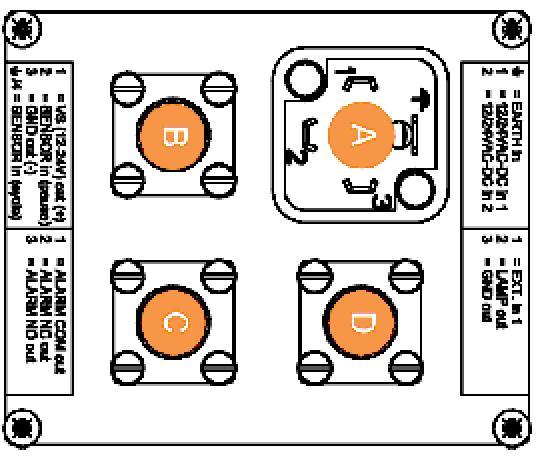
48 PULLER Model: ARS700 TABLE. (OPTIOAL) ) Machine connection cable. 2) Machine ground cable.
49
50 TYPE VISCOSITY (ISO 3448) Comparative table of suggested oils and greases HYDRAULIC CIRCUIT OIL FOR EVIROMETAL CODITIO: REDUCTIO UIT - COUPLERS REDUCTIO UIT OIL FOR EVIROMETAL CODITIO: ARTIC WITER SUMMER TROPICAL ARTIC WITER SUMMER TROPICAL GREASIG VG 22 VG 32 VG 46 VG 68 VG 00 VG 50 VG 220 VG 320 LGI 2 AGIP OSO 22 OSO 32 OSO 46 OSO 68 BLASIA 00 BLASIA 50 BLASIA 220 BLASIA 320 GR MU EP 2 API APILUBE CIS 22 APILUBE CIS 32 APILUBE CIS 46 APILUBE CIS 68 DT 00 DT 50 DT 220 DT 320 PGX 2 ARAL ARAL VITAM GF 22 ARAL VITAM GF 32 ARAL VITAM GF 46 ARAL VITAM GF 68 DEGOL BG 00 DEGOL BG 50 DEGOL BG 220 DEGOL BG 320 ARALUB HL 2 AVIA AVILUB RSL 22 AVILUB RSL 32 AVILUB RSL 46 AVILUB RSL 68 AVILUB RSX 00 AVILUB RSX 50 AVILUB RSX 220 AVILUB RSX BP EERGOL HLP 22 EERGOL HLP 32 EERGOL HLP 46 EERGOL HLP 68 EERGOL GR-XP 00 EERGOL GR-XP 50 EERGOL GR-XP 220 EERGOL GR-XP 320 GREASE LTX 2 CASTROL HYSPI AWS 22 HYSPI AWS 32 HYSPI AWS 46 HYSPI AWS 68 ALPHA SP 00 ALPHA SP 50 ALPHA SP 220 ALPHA SP 320 SUPERGREASE 2 CHEVRO EP HYDRAULIC 22 EP HYDRAULIC 32 EP HYDRAULIC 46 EP HYDRAULIC 68 COMPOUD GEAR 00 COMPOUD GEAR 50 COMPOUD GEAR 220 COMPOUD GEAR 320 DURALITH EP 2 ELF ELFOLA DS 22 ELFOLA DS 32 ELFOLA DS 46 ELFOLA DS 68 REDUCTELF SP 00 REDUCTELF SP 50 REDUCTELF SP 220 REDUCTELF SP 320 ROLEXA 2 ESSO UTO H 22 UTO H 32 UTO H 46 UTO H 68 SPARTA EP 00 SPARTA EP 50 SPARTA EP 220 SPARTA EP 320 BEACO 2 FIA HYDRA 22 HYDRA 32 HYDRA 46 HYDRA 68 GIRA 00 GIRA 50 GIRA 220 GIRA 320 MARSO EP L2 FUCHS REOLI MR 5 REOLI MR 0 REOLI MR 5 REOLI MR 20 - REEP COMPOUD 04 - REEP COMPOUD 08 - GREASE FOR EACH AMBIET GULF HARMOY 22 AW HARMOY 32 AW HARMOY 46 AW HARMOY 68 AW - EP LUBRICAT HD 50 EP LUBRICAT HD 220 EP LUBRICAT HD 320 CROW EP 2 IP HYDRUS OIL 22 HYDRUS OIL 32 HYDRUS OIL 46 HYDRUS OIL 68 MELLAA 00 MELLAA 50 MELLAA 220 MELLAA 320 ATHESIA EP GR 2 KLUBER LAMORA 22 LAMORA 32 LAMORA 46 LAMORA 68 LAMORA 00 LAMORA 50 LAMORA 220 LAMORA 320 CETOPLEX 2 EP MOBIL DTE 22 DTE 24 DTE 25 DTE 26 - MOBILGEAR 629 MOBILGEAR 630 MOBILGEAR 632 MOBILUX EP 2 Q8 HAYDI 22 HAYDI 32 HAYDI 46 HAYDI 68 GOYA 00 GOYA 50 GOYA 220 GOYA 320 REMBRADT EP 2 ROLOIL LI 22 LI 32 LI 46 LI 68 EP 00 EP 50 EP 220 EP 320 LITEX EP 2 SHELL TELLUS 22 TELLUS 32 TELLUS 46 TELLUS 68 OMALA 00 OMALA 50 OMALA 220 OMALA 320 SUPERGREASE EP2 SYECO - PACEMAKER 32 PACEMAKER 46 PACEMAKER 68 - PACEMAKER RODI 2 - PACEMAKER RODI 24 SIT GREASE EP 2 TAMOIL HYDRAULIC OIL 22 HYDRAULIC OIL 32 HYDRAULIC OIL 46 HYDRAULIC OIL 68 CARTER EP 00 CARTER EP 50 CARTER EP 220 CARTER EP 320 TAMLITH GREASE EP2 TEXACO RADO HD 22 RADO HD 32 RADO HD 46 RADO HD 68 MEROPA 00 MEROPA 50 MEROPA 220 MEROPA 320 MULTIFAK EP 2 TOTAL AZOLLA ZS 22 AZOLLA ZS 32 AZOLLA ZS 46 AZOLLA ZS 68 CARTER EP 00 CARTE EP 50 CARTER EP 220 CARTER EP 320 MULTIS EP 2 VALVOLIE ELIOS HVI 22 ELIOS HVI 32 ELIOS HVI 46 ELIOS HVI 58 ELIOS EP 00 ELIOS EP 50 ELIOS EP 220 ELIOS EP 320 LITHIUM BASE EP 2 Tavole Oli - 6/09/ Pagina di - GB
51 PULLER MOD. ARS70 ECLOSED DOCUMETS Grassobbio (Bg) via Zanica, 7/O Endine Gaiano (Bg) via Pertegalli Tel / 035 / Tel / 035 / Telefax 0039 / 035 / Telefax 0039 / 035 / info@tesmec.it info@tesmec.it
52 IMPORTATE Per qualsiasi informazione riguardante questa macchina/attrezzatura (utilizzo, manutenzione, ricambi) citare sempre Modello, umero di matricola, Commessa, Anno di fabbricazione rilevabile nella targa d'identificazione della macchina. Questo manuale non descrive le procedure di tesatura, né si è cercato di dare istruzioni all utilizzatore sui metodi di tesatura. Il contenuto di questo manuale prevede unicamente un testo di base per l uso, manutenzione e l elenco dei pezzi di ricambio della macchina stessa e come s'intende e si suggerisce di utilizzarla. Saranno graditi suggerimenti da parte degli Utilizzatori per migliorare questa pubblicazione. Scriveteci all indirizzo sottoindicato. IMPORTAT OTE State always Model, Serial umber and Manufacturing Year of the machine/equipment in case you need information on use, maintenance and spare parts. The a/m data can be found on the identification plate of the machine itself. This is not a stringing procedures manual, and no attempt is made or implied herein to instruct the user in stringing methods. The contents of this manual are intended as base line for operation, maintenance and part list of the unit as it stands alone and as it is intended and anticipated to be used. Recommendation by the individual user for improving this publication is encouraged and should be forwarded to the address on this page. IMPORTAT Indiquer toujours le modèle, le numéro de série et l année de fabrication de la machine/équipement même, en demandant à TESMEC renseignements sur l utilisation, l entretien et les pièces de rechange. Ces informations se trouvent sur la plaque d'identification de la machine. Ce manuel ne décrit pas les procédures de déroulage, ni on a tache de donner instructions à l'utilisateur sur les méthodes de déroulage. Le contenu de ce manuel prévoit seulement un texte pour l utilisation, l entretien et la liste de pièces de rechange et comme TESMEC conseille d utiliser la machine même. Pour chaque suggestion pour améliorer cette machine, écrire à l adresse au-dessous. IMPORTATE Para cualquier información relativa a esta máquina/equipo (utilización, mantenimiento, repuestos) citar siempre Modelo, úmero de serie, Orden de compra, Año de fabricación que se hallan en la tarjeta de identificación de la máquina. Este manual no describe los procedimientos de tensado y tampoco se ha tratado de dar instrucciones al utilizador acerca de los métodos de tensado. El contenido de este manual prevé únicamente un texto básico para el uso, mantenimiento y el listado de repuestos de la misma máquina y cómo se pretende y se sugiere utilizarla. Se apreciarán sugerencias por parte de los utilizadores para mejorar esta publicación. os pueden escribir a la dirección indicada abajo. IMPORTATE Para qualquer informação a respeito desta máquina/equipamento (utilização, manutenção, peças sobresselentes) citar sempre o Modelo, o úmero de Série, a Encomenda, o Ano de fabrico,dados que podem ser encontrados na placa de identificação da máquina. Este manual não descreve os procedimentos de entesadura, tão pouco foi nossa intenção dar instruções ao utilizador sobre os métodos de entesadura. O conteúdo deste manual de instruções prevê unicamente um texto básico para o uso, a manutenção e a lista das peças sobresselentes da mesma máquina e como se entende e se sugere utilizá-la. Serão muito bem aceitas sugestões por parte dos Utilizadores, no intento de melhorar esta publicação. Escrevam-nos no endereço abaixo indicado. WICHTIG Geben Sie für alle Informationen über diese Maschine/Ausrüstung (Verwendung, Wartung, Ersatzteile) immer Modell, Matrikelnummer, Bestellung und Baujahr an, was Sie dem Identifizierungsschild der Maschine entnehmen können. Dieses Handbuch beschreibt nicht die Verfahren des Spannens, und es wurde auch nicht versucht, dem Verwender Anleitungen über die Methoden des Spannens zu geben. Der Inhalt dieses Handbuchs enthält allein einen Basistext für den Gebrauch und die Wartung, die Ersatzteilliste der Maschine und außerdem, welche Verwendung für sie bezweckt und empfohlen wird. Wir freuen uns über Tipps von Seiten der Verwender, um diese Veröffentlichung zu verbessern. Schreiben Sie uns an unten angegebene Adresse. ВАЖНОЕ ПРИМЕЧАНИЕ Всегда следует указывать «модель, серийный номер и год выпуска» машины/оборудования в случае, если вам необходима информация по эксплуатации, техническому обслуживанию и запасным частям. Вышеупомянутые данные можно найти на паспортной табличке на самой машине. Руководство по эксплуатации не является руководством по методикам натяжения, и в нем не делается никаких попыток инструктирования пользователя способам натяжения, и они не подразумеваются. Цель настоящего руководства состоит только в том, чтобы дать описание эксплуатации и технического обслуживания, а также список запасных частей машины, и указать ее назначение и рекомендуемое использование. Рекомендации отдельных пользователей по улучшению данной публикации приветствуются, и их следует направлять по адресу, указанному в руководстве Grassobbio (Bg) via Zanica, 7/O Endine Gaiano (Bg) via Pertegalli Tel / 035 / Tel / 035 / Telefax 0039 / 035 / Telefax 0039 / 035 / info@tesmec.it info@tesmec.it
53
54
55 -S Starting Switch 30
56
57
58
59 JP
60 JP2
61 0 2
62
63
64
65
66
67
68
69
70
71
72
73
74
Sheet n 1 of 20 Doc. n WDMM/02/E MOD. WDMM INSTALLATION, USE AND SERVICE MANUAL. PETROL INSTRUMENTS S.r.l APRILIA (LT) - ITALY
 - ITALY") Sheet n 1 of 20 WATER DRAW/ MASTER METER PETROL COUNTER MOD. WDMM INSTALLATION, USE AND SERVICE MANUAL PETROL INSTRUMENTS S.r.l. - 04011 APRILIA (LT) - ITALY Sheet n 2 of 20 INSTALLATION, USE AND SERVICE
Sheet n 1 of 20 WATER DRAW/ MASTER METER PETROL COUNTER MOD. WDMM INSTALLATION, USE AND SERVICE MANUAL PETROL INSTRUMENTS S.r.l. - 04011 APRILIA (LT) - ITALY Sheet n 2 of 20 INSTALLATION, USE AND SERVICE
BELT CONVEYOR CB/M5 Series
 BELT CONVEYOR CB/M5 Series User and maintenance manual 1 DECLARATION OF CONFORMITY The company: Tel. +39-0444 450 620-451 520 Fax +39-0444 671 840 declares under its own responsibility that the machine
FRB518 Hydraulic Tensioner
 USER'S GUIDE & SAFETY MANUAL USER'S GUIDE & SAFETY MANUAL FRB518 Hydraulic Tensioner Important Safety Notice Before using a Condux Tesmec FRB518 Hydraulic Tensioner, operators must read and understand
CE DECLARATION OF MACHINE CONFORMITY
 CE DECLARATION OF MACHINE CONFORMITY (DIRECTIVE 2006/42/EC) Manufacturer : Address: Declares that: FAAC S.p.A. Via Calari, 10-40069 Zola Predosa BOLOGNA - ITALY Operator mod. 541 3ph is built to be incorporated
BELT CONVEYOR PNL/4 Series User and maintenance manual
 BELT CONVEYOR PNL/4 Series User and maintenance manual 1 DECLARATION OF CONFORMITY CE In conformity with the 2006/42/CE Machine Directives, Enclosure II, section A The company: VIRGINIO NASTRI S.r.l. Tel.
Drive Unit e-drive1. Installation instructions 04/2014. English translation of the original German installation instructions
 Drive Unit e-drive1 Installation instructions 04/2014 English translation of the original German installation instructions Contents Foreword... 3 Availability... 3 Structural features in the text... 3
Northern Sales & Distribution Centre
 User Manual Industrial Door Northern Sales & Distribution Centre The Door Centre, Discovery Park, Crossley Road, Stockport, SK4 5BW /indupart /indupart /indupart /company/indupart-ltd Foreword This user
Pump Manual. Model Numbers: SP240VDFS57LPM SP240VDFS80LPM. Product Names: Digital Refueling Station - 57 L/min Digital Refueling Station - 80 L/min
 Pump Manual Model Numbers: SP240VDFS57LPM SP240VDFS80LPM Product Names: Digital Refueling Station - 57 L/min Digital Refueling Station - 80 L/min Copyright: Scintex Fuel Depot 2012[Type text] Page 1 WARNING:
WELDING INVERTER. PEGAS 160 E Smart PEGAS 200 E Smart OPERATING MANUAL. ALFA IN a.s. PEGAS E Smart Manual EN 04
 WELDING INVERTER PEGAS 160 E Smart PEGAS 200 E Smart OPERATING MANUAL PEGAS 160-200 E Smart Manual EN 04 2/12 CONTENT: 1. INTRODUCTION... 3 2. SAFETY INSTRUCTIONS AND WARNINGS... 4 3. TECHNICAL DATA...
HPD Hydraulic Post Driver
 HPD Hydraulic Post Driver From serial No. 7600 Revised 04.01.2013 Prior to Operation We thank you for choosing a HYCON Post Driver. To ensure smooth operation and long-lasting performance of your new post
Contents. EC DECLARATION OF CONFORMITY FOR MACHINES... p. 10. WARNINGS FOR THE INSTALLER... p. 10
 Contents EC DECLARATION OF CONFORMITY FOR MACHINES... p. 10 WARNINGS FOR THE INSTALLER... p. 10 1. DESCRIPTION AND TECHNICAL SPECIFICATIONS... p. 11 1.1. DIMENSIONS... p. 11 2. ELECTRIC DEVICES (standard
OPERATION AND MAINTENANCE MANUAL
 WREN IBT SERIES HYDRAULIC TORQUE WRENCHES IBT SQUARE DRIVE SERIES OPERATION AND MAINTENANCE MANUAL FOR WREN Products: POINT 75, 1IBT, 3IBT, 5IBT, 8IBT, 10IBT, 20IBT, 25IBT, 35IBT, 50IBT SQUARE DRIVE HYDRAULIC
ROTARY TILLER TYPE "URT"
 Del Morino srl, v.caroni di Sotto 19, I-52033 Caprese Michelangelo AR Italy Ph: +39-575-791059 Fax: +39-575-791210 E.mail: export@del-morino.it http://www.del-morino.it USE AND MAINTENANCE MANUAL ROTARY
HH10/HH10RV Hydraulic Breaker
 Prior to Operation HH10/HH10RV Hydraulic Breaker HH10 from serial No. 1451 HH10RV from serial No. 2741 Revised 30.08.2011 We thank you for choosing a HYCON breaker. To ensure smooth operation and long-lasting
 Operation and Maintenance Manual Model.75,, 3, 5, 8, 0, 0, 5, 35, 50 http://www.torsionx.com Use the MaxDrv Series Square Drive Torque Wrench Model.75,, 3, 5, 8, 0, 0, 5, 35, 50 to install and remove threaded
Installation Manual. Swing Gate System. Leading the way...
 Installation Manual 402 Swing Gate System Leading the way... Contents EC DECLARATION OF CONFORMITY FOR MACHINES... p. 2 WARNINGS FOR THE INSTALLER... p. 2 1. DESCRIPTION AND TECHNICAL SPECIFICATIONS...
BAH series Use and Maintenance Manual
 Page 1 of 15 BAH 225-280 series Use and Maintenance Manual Page 2 of 15 We would like to thank you for trusting us and buying our product. Field of application Before starting the motor, it s necessary
Edition Manual Chapter Page Workshop Manual, Stiga Park 4 Hydraulic system 8
 2008-05-19 Workshop Manual, Stiga Park 4 Hydraulic system 8 The charge pump (1) and the main pump (2) are integrated into one unit, the hydraulic pump (C) which is located separat in front of the engine.
OPERATING INSTRUCTIONS
 OPERATING INSTRUCTIONS Release J 3x 200/240V 50/60 Hz 27/04/2010 23 Rue Colbert - 35300 FOUGERES (FRANCE) Tél. : 33.(0)2.99.99.14.87 - Fax : 33.(0)2.99.94.19.54 e-mail : contact@elco.eu TABLE OF CONTENTS
USER MANUAL FOR AUTOMATIC A/C CHARGING STATIONS
 USER MANUAL FOR AUTOMATIC A/C CHARGING STATIONS Nano Nano 2 Nano Hybrid ITECH Creative Technology INDEX 1 INTRODUCTION... 2 1.1 Safety instructions... 2 2 EQUIPMENT... 2 3 USE... 4 3.1 Control panel...
MGV25.X USER GUIDE. Ver. 3.7 INSTALLATION OPERATION AND MAINTENANCE MANUAL OF THE GEARLESS MGV25.2 MGV25.3 MGV25.5
 MGV25.X USER GUIDE INSTALLATION OPERATION AND MAINTENANCE MANUAL OF THE GEARLESS MGV25.2 MGV25.3 MGV25.5 Ver. 3.7 MONTANARI GIULIO & C. S.r.l. 41100 MODENA (Italy) Via Bulgaria,39 Tel. +39 059 45.36.11
Mod: KLD6-12/35XLAS-N
 12/2011 Mod: KLD6-12/35XLAS-N Production code: 1914070 INSTRUCTION MANUAL LOGIC LINE PLUS HOOD Reseller Stamp for Warranty Dear customer, Above all, thank you for choosing our product and we would like
Section 4.3. Machine Operation - Operating Procedures. Before Starting the Engine: General Pre-Start Inspection
 Section 4.3 Machine Operation - Operating Procedures Before Starting the Engine: General Pre-Start Inspection... 4.3.2 Engine Starting Procedure... 4.3.2 Cold Weather Start-Up... 4.3.3 Engine Shutdown
IBT Series Square Drive Torque Wrenches
 IBT Series Square Drive Torque Wrenches Operation and Maintenance Manual Model.75, 1, 3, 5, 8, 10, 20, 25, 35, 50 http://www.torsionx.com Use the IBT Series Square Drive Torque Wrenches Model.75, 1, 3,
CO 3-WAY PNEUMATIC VALVE INSTRUCTION MANUAL 2080
 CO 3-WAY PNEUMATIC VALVE INSTRUCTION MANUAL 2080 STI S.r.l has taken every care in collecting and verifying the documentation contained in this Instruction Manual. The information herein contained are
USO E MANUTENZIONE USE AND MAINTENANCE EMPLOI ET ENTRETIEN GEBRAUCH UND WARTUNG USO Y MANTENIMIENTO I GB F D E G25. roteritalia
 I GB F D E USO E MANUTENZIONE USE AND MAINTENANCE EMPLOI ET ENTRETIEN GEBRAUCH UND WARTUNG USO Y MANTENIMIENTO G25 roteritalia INDEX Technical data... page 2 Machine identification... page 2 Guarantee...
Grease Stand MODEL# DF MAINTENANCE AND OPERATION MANUAL. Page 1
 Grease Stand Page 1 WARNING Safety First Standards Tested in general accordance with the applicable requirements of DIN EN 131 2 : 2012 BS EN 131 7 : 2013 ANSI ASC A147 20 2011 The best insurance against
OPERATIONS MANUAL LEVER CHAIN HOIST
 OPERATIONS MANUAL LEVER CHAIN HOIST IMPORTANT SAFETY INFORMATION Please read, understand and follow all safety information contained in these instructions prior to the use of this hoist. Retain these instructions
SECTION 1-6 OPERATION OF INSTRUMENTS AND CONTROLS 05 HIGHLANDER_U (L/O 0409) Gauges, Meters and Service reminder indicators
 Gauges, Meters and Service reminder indicators") SECTION 1-6 OPERATION OF INSTRUMENTS AND CONTROLS Gauges, Meters and Service reminder indicators Fuel gauge................................................ 132 Engine coolant temperature gauge...........................
SECTION 1-6 OPERATION OF INSTRUMENTS AND CONTROLS Gauges, Meters and Service reminder indicators Fuel gauge................................................ 132 Engine coolant temperature gauge...........................
 Operation and Maintenance Manual http://www.torsionx.eu Use the MaxDrv Series Square Drive Torque Wrench Model.75, 1, 3, 5, 8, 10, 20, 25, 35, 50 to install and remove threaded fasteners requiring precise
Hydraulic Breakers HH35. Prior to Operation. From Serial No Revised We thank you for choosing a HYCON breaker.
 Hydraulic Breakers HH35 From Serial No. 12263 Revised 01.02.2015 Prior to Operation We thank you for choosing a HYCON breaker. To ensure smooth operation and long-lasting performance of your new breaker,
STRINGING EQUIPMENT CATALOGUE
 Antenna Construc on Winches for li ing and passenger li ing STRINGING EQUIPMENT CATALOGUE PULLER FOR LIFTING PASSENGERS Model: SPW 2,5 - P Bull wheel Puller with integrated reel winder switchable between
Operating instructions ErgoPack 600 E
 Operating instructions ErgoPack 600 E Operation of the device is only permitted if the operating instructions have been carefully read and understood before use! Declaration of conformity EU declaration
ASSEMBLY INSTRUCTIONS L-LINE KTG ZMA0304GB
 ASSEMBLY INSTRUCTIONS L-LINE KTG ZMA0304GB 2012-12-01 Delivery information Goods inspection Check that the number of packages agrees with the delivery note and that the packing and goods are not damaged.
SUSPENSION MODULE by
 SUSPENSION MODULE by Dear Customer, thank you for choosing Land Rover Passion and for purchasing the suspension module Easy Lift. This product has been designed and manufactured respecting the highest
SAFETY- FLY 700 P USER MANUAL FLYING INSTRUMENT FOR ULTRALIGHT AIRCRAFTS NR MIT
 SAFETY- FLY 700 P FLYING INSTRUMENT FOR ULTRALIGHT AIRCRAFTS NR.1017.2 MIT USER MANUAL UK Manufacturer Preface : MC elettronica S.r.l. Address : Via E. fermi, 450/486 Fiesso Umbertiano (ROVIGO) - ITALY
Section 4.3. Machine Operation - Operating Procedures. Before Starting the Engine: General Pre-Start Inspection
 Section 4.3 Machine Operation - Operating Procedures Before Starting the Engine: General Pre-Start Inspection... 4.3.2 Engine Starting Procedure... 4.3.2 Cold Weather Start-Up... 4.3.3 Engine Shutdown
OLYMPIAN MODEL 740 Operation and Service Manual
 OLYMPIAN MODEL 740 Operation and Service Manual P/N 133911-102 FCI MANUAL P/N 133865-001 Data herein has been verified and validated and believed adequate for the intended use. If the machine or procedures
Sample Hybrid Storyboard Draft B Articulated Trucks Module Two: Basic Operating Procedures This Storyboard was originally 139 slides in length.
 Sample Hybrid Storyboard Draft B Articulated Trucks Module Two: Basic Operating Procedures This Storyboard was originally 139 slides in length. There is no continuity between slides. Notes to SMEs Reference
Lincoln Hoist. Web Hoist Operating Manual. Lincoln Hoist
 Lincoln Hoist Web Hoist Operating Manual Lincoln Hoist Mfg. by Lincoln Precision Machining Company 121 Creeper Hill Road, P.O. Box 458, North Grafton, MA 01536 USA Toll Free (888) 306-7222 Phone (774)
1500 Series Roll Off Hoist. Owner s Manual (5-06)
") 1500 Series Roll Off Hoist Owner s Manual (5-06) Section 1: General Information Introduction Safety Information Warranty Information Table of Contents Section 2: Operation Operating the P.T.O. Operating
1500 Series Roll Off Hoist Owner s Manual (5-06) Section 1: General Information Introduction Safety Information Warranty Information Table of Contents Section 2: Operation Operating the P.T.O. Operating
The Specification EB12E Series Semi-Electric Stacker
 1 The Specification EB12E Series Semi-Electric Stacker Note: Before using, please read this manual! EKKO Material Handling Equipment Manufacturing, Inc. 1 - 1 - Contents 1. The correct use of Electric
MULTIVOLTAGE PORTABLE BATTERY CHARGER MVM
 _ M MULTIVOLTAGE PORTABLE BATTERY CHARGER MVM User's MANUAL Code: MVM Version: 01-BF Date: OCT 2005 Page 1/10 _ 1. INTRODUCTION Before starting to use your Energic plus MVM battery charger, please take
AU DU PONT DE LUTTRE BRUSSELS BELGIUM PHONE: FAX: OPERATING MANUAL. Electric Fully Automatic Floor Saw FS 1218 EX
 AU DU PONT DE LUTTRE 74-1190 BRUSSELS BELGIUM PHONE: 322 34 83 162 FAX: 322 34 83 136 OPERATING MANUAL Electric Fully Automatic Floor Saw FS 1218 EX 2 Important information before you start! When the machine
RUFNEX Series Low Profile Wrenches Operation and Maintenance Manual
 RUFNEX Series Low Profile Wrenches Operation and Maintenance Manual http://www.torsionx.com Use the RUFNEX Series Ultra-Low Profile Wrenches to install and remove large bolts that have minimal wrench clearance.
Portable Lighting Equipment Operating Instructions Table of Contents
 Portable Lighting Equipment Operating Instructions Table of Generac Magnum Ingersoll Rand TEREX AMIDA TEREX GENIE Model: MLT3060 Model: LIGHTSOURCE Model: Amida AL4000 series Model: TML4000N Generac Magnum
SM825 ver.t Semi-Automatic Car Tire Changer Manual
 SM825 ver.t Semi-Automatic Car Tire Changer Manual REV. 01 1 / 28 PRINTING CHARACTERS AND SYMBOLS Throughout this manual, the following symbols and printing characters are used to facilitate reading: Indicates
Folding aggregates. Oil lubrication. Use and maintenance manual
 Folding aggregates Oil lubrication Use and maintenance manual 2 MC S.r.l. - 580103600gb.fm140208 Publication information Publication information Copyright 2008 MC S.r.l.. All rights reserved. Code Edition
SERVO MOTORS BRUSHLESS SERVO MOTORS OPERATING INSTRUCTIONS 2016
 SERVO MOTORS BRUSHLESS SERVO MOTORS OPERATING INSTRUCTIONS 2016 3009/16 en Ed.02.2016 Read these Operating Instructions before performing any transportation, installation, commissioning, maintenance or
HexPro Series Low Profile Wrenches
 HexPro Series Low Profile Wrenches Operation and Maintenance Manual Model 2HP 4HP 8HP 14HP 30HP www.torquetoolsinc.com Use the HEXPRO Series Low Profile Wrenches Model 2HP 4HP 8HP 14HP 30HP to install
SIZING OF SOLAR GENERATOR
 MULTI ISLAND is a water pumping system with power from photovoltaic panels. It is designed for use in water wells, irrigation systems, or the power supply network is not available, or when the user wishes
R3 Roller Garage Door Opener
 R3 Roller Garage Door Opener INSTALLATION INSTRUCTIONS OWNERS COPY 1 WARNING: It is vital for the safety of persons to follow all instructions. Failure to comply with the installation instructions and
MAINTENANCE AND USER MANUAL SPARE PARTS CONFORMITY TO EC STANDARDS TRANSLATION OF THE ORIGINAL 2 COLUMN ELECTRO-HYDRAULIC VEHICLE LIFT FZ61/3S
 MAINTENANCE AND USER MANUAL SPARE PARTS CONFORMITY TO EC STANDARDS TRANSLATION OF THE ORIGINAL 2 COLUMN ELECTRO-HYDRAULIC VEHICLE LIFT FZ61/3S Issue 06/2013 GB Thank you for having chosen a Eurolift vehicle
Operating Instructions BNT-40 Automatic Rebar Tying Machine
 Operating Instructions BNT-40 Automatic Rebar Tying Machine This Tool Has Passed ISO9001 International Quality System Certification The charger has passed ETL Certification BNT-40 Technical Manual.indd
BELT CONVEYOR CBD/8 Series
 BELT CONVEYOR CBD/8 Series User and maintenance manual 1 DECLARATION OF CONFORMITY CE In conformity with the 2006/42/CE Machine Directives, Enclosure II, section A The company: VIRGINIO NASTRI S.r.l. Tel.
Instruction Manual MB4 Rolling garage door opener
 Instruction Manual MB4 Rolling garage door opener INSTALLATION INSTRUCTIONS OWNERS COPY 1 WARNING: It is vital for the safety of persons to follow all instructions. Failure to comply with the installation
INSTALLATION, OPERATION AND MAINTENANCE TECHNICAL MANUAL
 ISO 9001:2008 Via Renata Bianchi, 12 16152 Genova ITALY Tel. +39.01.6017016 Fax. +39-010-601-6021 www.tecnidro.com s INDEX 1. Introduction 1.1 Premise 1.2 Generality 1.3 Principle of operation 2. INSTALLATION
Model E600 Tarping System
 10 Boulder Parkway N. Oxford, MA 01537 866-353-5826 pioneersales@wastequip.com www.pioneercoverall.com Model E600 Tarping System Installation Instructions WARNING: In order to prevent damage, the tarp
Operating Instructions Flexdip CYA112
 BA00432C/07/EN/13.13 71207066 Products Solutions Services Operating Instructions Wastewater assembly About this document Safety messages The structure, signal words and safety colors of the signs comply
SPECIFICATIONS GENERAL SAFETY RULES PERSONAL SAFETY. Save This Manual TOOL USE AND CARE WORK AREA
 SPECIFICATIONS 2 Forged Safety Latch Hooks Cable extends to: 44 Drop forged steel hanging bracket Heavy duty 3/16 Steel Cable Pulling Capacity: 1200 LB. One piece double ratchet gear Save This Manual You
MANUAL ET13MH ET15MH PL3000EA
 OPE RATI ON&S E RVI CE MANUAL ET13MH ET15MH PL3000EA WARNING! WARNING! Do not use the truck before first reading through this MANUAL. NOTE! Keep for future reference. 1 Operation & Service Manual FOREWORD
FTFR Maintenance and Parts Manual SQ-1 FLOOR TRUSS FINISH ROLLER. Operators Manual
 FTFR Maintenance and Parts Manual SQ-1 FLOOR TRUSS FINISH ROLLER Operators Manual FOREWORD This manual explains the proper maintenance of Square 1 Design Floor Truss Finish Roller as well as the daily
Property of American Airlines
 Vestergaard - VTS ON 1973 (1-4) American Airlines CHAPTER OPERATING MANUAL 2.1 OPERATING THE VTS In this chapter, we will go through operation of the VTS point by point. When appropriate, references will
Spa USE AND MAINTENANCE CULTIVATOR MODEL BL300 / BL350
 Spa USE AND MAINTENANCE CULTIVATOR MODEL BL300 / BL350 02/12/2008 INDEX INTRODUCTION TECHNICAL DETAILS GENERAL SAFETY REGULATIONS STARTING AND STOPPING USE AND ADJUSTMENT SERVICING TESTS FOR CE REGULATIONS
GLO-502/530 (RIM CLAMP TIRE CHANGER)
") GLO-502/530 (RIM CLAMP TIRE CHANGER) OPERATION MANUAL DATE INSTALLED: SERIAL # MANUFACTURING DATE: (EAGLE - GLOBAL : NHT) TABLE OF CONTENT INTRODUCTION -------------------------------------------------------------------------------2
GLO-502/530 (RIM CLAMP TIRE CHANGER) OPERATION MANUAL DATE INSTALLED: SERIAL # MANUFACTURING DATE: (EAGLE - GLOBAL : NHT) TABLE OF CONTENT INTRODUCTION -------------------------------------------------------------------------------2
OPERATING AND MAINTENANCE INSTRUCTIONS HYDRAULIC ELECTRICAL PUMPS HAM (Manual control) HAE (Electrical control)
 HAE (Electrical control)") OPERATING AND MAINTENANCE INSTRUCTIONS HYDRAULIC ELECTRICAL PUMPS HAM (Manual control) HAE (Electrical control) Part Nr : HA M 4 6 2 1 B C 1. Essential safety requirements. 2. Technical Characteristics.
OPERATING AND MAINTENANCE INSTRUCTIONS HYDRAULIC ELECTRICAL PUMPS HAM (Manual control) HAE (Electrical control) Part Nr : HA M 4 6 2 1 B C 1. Essential safety requirements. 2. Technical Characteristics.
Low Profile Wrenches Operation and Maintenance Manual
 Low Profile Wrenches Operation and Maintenance Manual http://www.torquetoolsinc.com Use the HEXPRO Series Low Profile Wrenches Model 2HP 4HP 8HP 14HP 30HP to install and remove large bolts that have minimal
AGRI-COVERTM SWITCH CONTROL INSTRUCTIONS
 AGRI-COVERTM SWITCH CONTROL INSTRUCTIONS Use these instructions in place of the rocker switch and solenoid sections in your roll tarp or ROLTECTM Electric Hopper Conversion instructions. Some installs
Part 1 OPERATION OF INSTRUMENTS AND CONTROLS
 Part 1 OPERATION OF INSTRUMENTS AND CONTROLS Chapter 1-5 Gauges, Meters and Service reminder indicators Fuel gauge Engine coolant temperature gauge Oil pressure gauge Voltmeter Tachometer Odometer and
PCBL 1600/1800 POWER WHEELCHAIR MODERN USER'S MANUAL Edition
 PCBL 1600/1800 POWER WHEELCHAIR MODERN USER'S MANUAL Edition 09.2013 mdh sp. z o.o. 90-349 Łódź, ul. Tymienieckiego 22/24 tel. (+48) 42 212 32 08 fax: (+48) 42 674 04 99 www.mdh.pl viteacare@mdh.pl 1 TABLE
SARGON S - M - L. All rights reserved INSTALLATION MANUAL
 INSTALLATION MANUAL Our compliments for your excellent choice. SARGON LINE S (300mm) M (400mm) and L (600mm) electro-mechanical gear motor has been produced for reliability and high quality. This Manual
POMPE AUTOADESCANTI SELF-PRIMING ELECTRO PUMP ACM DISASSEMBLY AND ASSEMBLY INSTRUCTIONS FOR MULTISTAGE SELF-PRIMING PUMPS
 POMPE AUTOADESCANTI SELF-PRIMING ELECTRO PUMP ACM DISASSEMBLY AND ASSEMBLY INSTRUCTIONS FOR MULTISTAGE SELF-PRIMING PUMPS Ed. 02/2011 5 WARNING These instructions are for the maintenance personnel for
Installation and Operating Instructions. Gravity Band Filter Typ PF
 Installation and Operating Instructions Gravity Band Filter Typ PF GB Table of contents Page 1 Description of product and function... 5 2 Safety instructions... 6 2.1 General instructions... 6 2.2 Instructions
User s Guide. Unwinder/Winder 100 FOR. Blizzard 65/90 Spitfire 65/90 Extreme Rockhopper 3 Extreme ValueJet 1604 ValueJet 1614 Viper 65/90 Viper 100
 User s Guide Unwinder/Winder 100 FOR Blizzard 65/90 Spitfire 65/90 Extreme Rockhopper 3 Extreme ValueJet 1604 ValueJet 1614 Viper 65/90 Viper 100 This page is intentionally left blank 2 AP-75101, Rev.2.3,
INSTRUCTION MANUAL INDUSTRIAL PERISTALTIC PUMPS MODEL RBT-70
 INSTRUCTION MANUAL INDUSTRIAL PERISTALTIC PUMPS MODEL RBT-70 This manual forms an integral part of the pump and must accompany it until its demolition. The series FMP peristaltic pump is a machine destined
FITTING AND CONNECTION INSTRUCTIONS
 LEPUS is an oil-bathed motor-reducer created for sliding gates automation. The motor-reducer irreversibility allows a perfect and safe gate closing avoiding the setup of an electrolock and in case of power
Operating and Maintenance Manual. for. HADEF overhead crane. as jointed crane TA
 5.52.714.00.1.0 Edition 03.2004 GB Operating and Maintenance Manual for HADEF overhead crane as jointed crane TA Subject to changes. 1 HADEF Table of Contents 1 General Page 3 2 Product description Page
SERVICE MANUAL (2)
") Terra 128B - 132B SERVICE MANUAL 146 0721 000(2)2003-04 INDEX GENERAL INFORMATION 3 MACHINE LIFTING 3 MACHINE TRANSPORTATION 3 OTHER AVAILABLE MANUALS 3 SAFETY - ACCIDENT PREVENTION 4 GENERAL SAFETY RULES
Terra 128B - 132B SERVICE MANUAL 146 0721 000(2)2003-04 INDEX GENERAL INFORMATION 3 MACHINE LIFTING 3 MACHINE TRANSPORTATION 3 OTHER AVAILABLE MANUALS 3 SAFETY - ACCIDENT PREVENTION 4 GENERAL SAFETY RULES
KENT/Euroclean MODELS: (2)
") Razor 17B - 20B - 20BT SERVICE MANUAL KENT/Euroclean MODELS: 908 7010 020-908 7011 020-908 7025 020 08603953(2)2003-09 INDEX GENERAL INFORMATION 3 MACHINE LIFTING 3 MACHINE TRANSPORTATION 3 OTHER AVAILABLE
Razor 17B - 20B - 20BT SERVICE MANUAL KENT/Euroclean MODELS: 908 7010 020-908 7011 020-908 7025 020 08603953(2)2003-09 INDEX GENERAL INFORMATION 3 MACHINE LIFTING 3 MACHINE TRANSPORTATION 3 OTHER AVAILABLE
INSTRUCTION MANUAL_1219_ENGLISH SUPER ELF X3. Operating Instructions for DORNIER looms. Robustness Reliability Quality Productivity Versatility
 INSTRUCTION MANUAL_1219_ENGLISH SUPER ELF X3 Operating Instructions for DORNIER looms Robustness Reliability Quality Productivity Versatility WARNING! - Condensation could form on the Weft Feeder when
MGV25.X USER GUIDE. Ver. 3.1 INSTALLATION OPERATION AND MAINTENANCE MANUAL OF THE GEARLESS MGV25.X
 MGV25.X USER GUIDE INSTALLATION OPERATION AND MAINTENANCE MANUAL OF THE GEARLESS MGV25.X Ver. 3.1 MONTANARI GIULIO & C. S.r.l. 41100 MODENA (Italy) Via Bulgaria,39 Tel. +39 059 45.36.11 Fax +39 059 31.58.90
NEW STINGER SYSTEM 1 INTRODUCTION Alstom Transport
 1 INTRODUCTION Alstom Transport NEW STINGER SYSTEM SUMMARY 1. INTRODUCTION... 3 2. APPLICATION PURPOSE... 3 3. PRODUCT DESCRIPTION... 4 3.1. INSULATED CONDUCTOR RAIL SYSTEM FOR ENERGY SUPPLY... 5 3.1.1.
MODEL HD99 HYDRAULIC ONE MAN TOWABLE EARTHDRILL
 DO NOT THROW AWAY IMPORTANT MANUAL MODEL HD99 HYDRAULIC ONE MAN TOWABLE EARTHDRILL Operators Manual GROUND HOG, INC. P.O.BOX 290 San Bernardino, CA. 92402 Phone (909) 478-5700 Fax (909) 478-5710 E-mail:
RH722 Instruction Manual
 5652-71352 RH722 Instruction Manual Introduction Thank you for purchasing this Car Mate INNO Winter. Before using your new Car Mate INNO Winter, please read through this instruction manual carefully, and
EC DECLARATION OF CONFORMITY FOR MACHINES (DIRECTIVE 98/37/EC) WARNINGS FOR THE INSTALLER
 WARNINGS FOR THE INSTALLER") EC DECLARATION OF CONFORMITY FOR MACHINES (DIRECTIVE 98/37/EC) Manufacturer: Address: Declares that: FAAC S.p.A. Via Benini, 1-40069 Zola Predosa BOLOGNA - ITALY 740-24V mod. operator is built to be integrated
EC DECLARATION OF CONFORMITY FOR MACHINES (DIRECTIVE 98/37/EC) Manufacturer: Address: Declares that: FAAC S.p.A. Via Benini, 1-40069 Zola Predosa BOLOGNA - ITALY 740-24V mod. operator is built to be integrated
RONDINI SQTF. The spreader cannot be used for other purposes than those ones for which had been designed.
 RONDINI SQTF 1 - How to use the machine The spreader cannot be used for other purposes than those ones for which had been designed. The liability is null and void in case of damages occurred when the machine
Towing and Road Service Guide For the 2003 Saab 9.3 Sedan. Quality and Education Services AAA Automotive 1000 AAA Drive Heathrow, FL 32746
 Towing and Road Service Guide For the 2003 Saab 9.3 Sedan Quality and Education Services AAA Automotive 1000 AAA Drive Heathrow, FL 32746 July 23, 2003 Index Equipment availability 3 General Towing Information
Maintenance and Operation Manual for Landing Gear Access Stand
 Maintenance and Operation Manual for Landing Gear Access Stand DF071592 03 Liftsafe Fall Protection Inc. Landing Gear Access Stand Manual Page 1 Table of Contents Section Page Number 1.0 Standards 3 2.0
Operating and Installation Instructions Diaphragm Vacuum Pumps and Compressors
 Operating and Installation Instructions Diaphragm Vacuum Pumps and Compressors Type range: UN813.3ANI UN813.4ANI UN813.3ANDCB UN813.4ANDCB UN813.5ANI Fig. 1: UN813.3ANI Fig. 2: UN813.4ANI You have selected
Safety and service recommendations for wheels
 Safety and service recommendations for wheels Developed by EUWA - Association of European Wheel Manufacturers Members of Euwa represent the main manufacturers of wheels, for all types of vehicles The wheel
Overhead lift Roomer 5200
 USER S MANUAL Overhead lift Roomer 5200 The Roomer 5200 offers you the unique ability to lift and move a patient from one room to another. The lift is equipped with two belts. When transferring from room
RAPID ROLLER OPERATOR S MANUAL. L&C ENTERPRISES - U.S.A, Inc N.75 Drive, Escanaba, MI OWNER S NAME MODEL
 RAPID ROLLER OPERATOR S MANUAL OWNER S NAME MODEL SERIAL NUMBER DATE OF PURCHASE L&C ENTERPRISES - U.S.A, Inc. 6652 N.75 Drive, Escanaba, MI 49829 906-786-1008 1-866-786-1009 LIMITED WARRANTY L&C Enterprises-USA,
LABORATORY MICROMOTOR HP45 MULTIFUNCTION
 LABORATORY MICROMOTOR HP45 MULTIFUNCTION USER AND MAINTENANCE MANUAL 1. DESCRIPTION HP45 Multifunction is a powerful and reliable micromotor, expressly designed for daily use in the Dental, Gold and Jewellery
HYDRAULIC BENDER VA1225 VC1225 VA1227 VB1227
 HYDRAULIC BENDER VA1225 VC1225 VA1227 VB1227 LARZEP, S.A. LARZEP AUSTRALIA PTY. LTD. LARZEP GB LTD. Avenida Urtiaga, 6 104 Wedgewood Road, 3 Commerce Way Leighton Buzzard 48269 MALLABIA, SPAIN HALLAM,
Star Swivel-Arm Hoist Installation and Operating Instructions
 Star Swivel-Arm Hoist Installation and Operating Instructions Conveying & Hoisting Solutions P/L ABN 78 6 7. Purpose of Equipment Star Swivel-Arm Hoists are intended for the transport of materials. Star
Hawk Enterprises of Elkhart THE BRUTE Owner s Manual
 Hawk Enterprises of Elkhart THE BRUTE Owner s Manual Operation Care Service COMMERICAL/INDUSTRIAL DUTY STONE RESTORATION MACHINE 13, 15, 17, 20 165 RPM 1.5 HP 180 FRAME TOTALLY ENCLOSED FAN COVERED MOTOR
Installation and operating instructions. Solar charge controller MPPT 10 A / 20 A Z Z
 Installation and operating instructions Solar charge controller MPPT 10 A / 20 A EN 1 Contents 1. About these instructions... 3 1.1 Applicability... 3 1.2 Users... 3 1.3 Description of symbols... 3 2.
BRAKE E
 8-1 GENERAL...8-2 SPECIFICATIONS...8-6 COMPONENTS...8-7 FRONT BRAKE...8-12 DISASSEMBLY INSPECTION REASSEMBLY (Pn1, Cu2 3 TON SERIES)...8-12 DISASSEMBLY INSPECTION REASSEMBLY (Pn2 3 TON SERIES)...8-17 BRAKE
Installation & Operation manual
 Installation & Operation manual TESA Electronic and special devices - via Etiopia 7-65015 Montesilvano PE - ITALY Tel. (0039) 085 4175602 info@tesaitaly.com www.tesaitaly.com Distributed in the U.K. by
Index. 4. DESCRIPTION... p PRELIMINARY CHECKS... p ASSEMBLY... p. 6
 D1000 Index GENERAL SAFETY INSTRUCTIONS FOR INSTALLATION AND MAINTENANCE... p. 2 TOOLS AND MATERIALS... p. 2 DECLARATION OF CONFORMITY... p. 3 WARNINGS FOR THE INSTALLER... p. 3 1. DIMENSIONS... p. 4 2.