SM825 ver.t Semi-Automatic Car Tire Changer Manual
|
|
|
- Christian Butler
- 5 years ago
- Views:
Transcription


1 SM825 ver.t Semi-Automatic Car Tire Changer Manual REV / 28
2 PRINTING CHARACTERS AND SYMBOLS Throughout this manual, the following symbols and printing characters are used to facilitate reading: Indicates the operations which need proper care Indicates prohibition Indicates a possibility of danger for the operators BOLD TYPE Important information WARNING: before operating the lift and carrying out any adjustment, read carefully chapter 7 installation where all proper operations for a better functioning of the lift are shown. REV / 28
3 CONTENTS 1 INTRODUCTION 4 2 GENERAL INFORMATION 6 3 TRANSPORT, UNPACKING AND STORAGE 9 4 INSTALLATION 10 5 OPERATION 16 6 INFLATING 20 7 MAINTENANCE 22 8 TROUBLESHOOTING 24 9 ELECTRIC AND PNEUMATIC DIAGRAM 25 REV / 28
4 CHAPTER 1 INTRODUCTION 1.1 INTRODUCTION Thank you for purchasing a product from the line of tire changers. The machine has been manufactured in accordance with the very best quality principles. Follow the simple instructions provided in this manual to ensure the correct operation and long life of the machine. Read the entire manual thoroughly and make sure you understand it. 1.2 TYRE CHANGER IDENTIFICATION DATA A complete description of the Tire Changer Model and the Serial number will make it easier for our technical assistance to provide service and will facilitate delivery of any required spare parts. For clarity and convenience, we have inserted the data of your tire changer in the box below. If there is any discrepancy between the data provided in this manual and that shown on the plate fixed to the tire changer, the latter should be taken as correct. LOGO Type: Volt Amp Kw Ph Hz Year of manufacturing: Air supply: 8-10 bar ( PSI) 1.3 MANUAL KEEPING For a proper use of this manual, the following is recommended: Keep the manual near the lift, in an easily accessible place. Keep the manual in an area protected from the damp. Use this manual properly without damaging it. Any use of the machine made by operators who are not familiar with the instructions and procedures contained herein shall be forbidden. This manual is an integral part of the manual: it shall be given to the new owner if and when the machine is resold. The illustrations have been made out of prototypes pictures. It is therefore possible that some parts or components of standard production differ from those represented in the pictures. 1.4 GENERAL SAFETY PRECAUTIONS The tire changer may only be used by specially trained and authorized expert personnel. REV / 28
5 Any tampering or modification to the equipment carried out without the manufacturer s prior authorization will free him from all responsibility for damage caused directly or indirectly by the above actions. Removing or tampering with safety devices immediately invalidates the guarantee. The tire changer comes complete with instruction and warning transfers which are designed to be long-lasting. If they should for any reason be damaged or destroyed, please ask immediately for replacements from the manufacturer. TO THE READER Every effort has been made to ensure that the information contained in this manual is correct, complete and up-to date. The manufacturer is not liable for any mistakes made when drawing up this manual and reserves the right to make any changes due the development of the product, at any time REV / 28


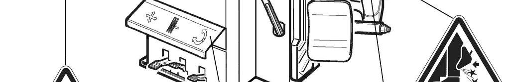
6 CHAPTER 2 GENERAL INFORMATION 2.1 INTENDED USE This Semi-automatic tire changer has been designed and manufactured exclusively for removing and mounting tires from/onto rims from 10" to 26" and a maximum diameter of 1000 mm. In particular THE MANUFACTURER cannot be held responsible for any damage caused through the use of this tire changer for purposes other than those specified in this manual, and therefore inappropriate, incorrect and unreasonable. 2.2 DESCRIPTION G) Clamps I) Mounting head M) Mounting bar N) Horizontal arm P) Vertical arm Q) Air supply R) Bead breaker S) Wheel support T) Bead lifting lever U) Clamp control pedal V) Clamp control pedal Z) Reverser control pedal Y) Turntable K) Locking lever Fig. 1 REV / 28


7 2.3 DANGER WARNING SIGNS REV / 28
8 2.4 TECHNICAL SPECIFICATION External locking rim dimension Internal locking rim dimension 12" - 26" 13" - 27" 14" - 28" 14" 28 15" - 29" 16" - 30" Max. tire diameter 1200mm (47.5 ) Max tire width 470mm (18.5 ) Force on bead breaker blade (10 bar) Working pressure Inflating pressure device max. Power supply voltage Motor power Rotating speed Max spindle torch 2500 kg 8 bar (116 psi) 3.5 bar (50 psi) 400V 3 Ph 230V 1Ph 110V 1PH 0.55 (400V 3 ph single speed) 0.8/1.1 kw (400V 3ph double speed) 0.75 kw (230V 1ph) 1.1KW (110V 1ph) 7 14 rpm 1200 NM Dimension 1140 x 1100 x 950 Net weight Noise level in working condition 240 kg STND < 70 db (A) REV / 28
9 CHAPTER 3 TRANSPORTATION, UNPACKING AND STORAGE 3.1 TRANSPORTATION The tire changer must be transported in its original packaging and kept in the position shown on the package itself. The packaged machine may be moved by means of a fork lift truck of suitable capacity. Insert the forks at the points shown in figure UNPACKING Remove the protective cardboard and the nylon bag. Check that the equipment is in perfect condition, making sure that no parts are damaged or missing. Use fig. 1 for reference. If in doubt do not use the machine and contact your retailer. 3.3 STORAGE In the event of storage for long periods of time, be sure to disconnect all sources of power and grease the clamp sliding guides on the turntable to prevent them from oxidizing. REV / 28

10 CHAPTER 4 INSTALLATION 4.1 SPACE REQUIRED When choosing the place of installation be sure that it complies with current safety at work regulations. The tire changer must be connected to the main electric power supply and the compressed air system. It is therefore advisable to install the machine near these power sources. The place of installation must also provide at least the space shown in pictures 4-4/A so as to allow all parts of the machine to operate correctly and without any restriction. If the machine is installed outside it must be protected by a lean-to. The tire changer with electric motor cannot be used in explosive atmospheres, unless it is a proper version. REV / 28
11 4.2 POSITIONING AND PARTS ASSEMBLY Unscrew the pallet fixing screws and set the tire changer on the floor. Unscrew the 4 screws from the body, set the vertical arm into the proper seat and fix the screw again (Fig. 5/a). Make sure the horizontal arm is on the vertical arm s support and the pin is locked with nuts and washers as shown in Fig. 5/b. Before connecting all the power sources ALWAYS check your installations. They must exactly correspond to those requested by the machine. Connect the machine to the compressed air network (Fig. 5/d) Mount the bead breaker arm as shown in Fig. 5/e: - Set the arm a into the proper seat, set the screw into the hole and screw the nut WITHOUT TIGHTENING. - Set the pivot pin b into the hole on the arm and let the cylinder s shaft pass through the pin s hole. Screw two nuts WITHOUT TIGHTENING. - Set the spring by hooking it at the indicated points. Screw the bead breaker arm s screw as indicated in Fig 5/f Screw the nut as indicated in Fig 5/g REV / 28
12 REV / 28
13 4.2.2 Mounting and connecting the GT Route the tube (1), situated inside the machine body, though the hole on the back side of the body. Connect the hose (4) to the connectors (2) using the bands (3) Mounting and connecting the manometer Fix the manometer to the vertical arm through the proper screw. Fig. 11. Route the connecting spiral hose through the small hole on the back side of the machine body. Connect the rilsan hose to the union of the pressure limiting device, situated on the inflating pedal. REV / 28

14 4.3 COMMISSIONING Any electric connection job must be carried out by professionally qualified personnel. Make sure that the power supply is right. Make sure the connection of the phases is right. Improper electrical hook-up can damage motor and will not be covered under warranty. Check to make sure the characteristics of your systems correspond to those required by the machine. If you have to change the machine s operating voltage, make the necessary adjustments to the terminal board referring to the electric diagram in chapter 9. Connect the machine to the compressed air system by means of the air connection (Q) that protrudes from the rear section. 4.4 OPERATING TESTS Connect the machine to the electric network, which must be provided with line fuses, a good earth plate in compliance with regulations in force and it must be connected to an automatic circuit breaker (differential) set at 30 ma. Should the tire-changer be lacking in electric plug, the user must set one, which is at least 16 A and which conforms to the voltage of the machine, in compliance with the regulations in force. When pedal (Z) is pressed down the turntable (Y) should turn in a clockwise direction. When pedal is pulled up the turntable should turn in an anticlockwise direction. If the turntable turns in the opposite direction to that shown, reverse two of the wires in the tree-phase plug. Pressing the pedal (U) activates the bead breaker (R); when the pedal is released the bead breaker returns to its original position. Pressing the pedal (V) opens the four clamps (G); when the pedal is pressed again they close. Pressing the trigger on the airline gauge cause air to be released from the head. REV / 28
15 4.4.1 GT version Do NOT LEAN on the turntable during this operation. Possibly dirty dust on turntable could offend the operator s eyes. For the same reason, be carefully as not to accidentally push the inflating pedal while working. When the pedal located on the left side of the machine body is pushed down to its intermediate position (B), air is released from the airline gauge. When the pedal (C) is pushed down completely, air is released from the airline gauge with a powerful jet from the nozzles located on the turntable clamps. 4.5 TURNTABLE LOCKING VALUE ADJUSTING Fig. 13 The tire changer turntable is preset by the manufacturer on a middle range measure from12 to 28 ext. (considering the rim outer side and) from int. (if you lock the rim from inner side). It is however possible to change this dimension range in case of need when working on larger or small rims; it is enough to change the position of the 4 clamps are shown in the figures below. The obtainable value starts from a minimum of ext. and int. until a maximum of ext. and int. To change the position, proceed as follows: Unscrew screw (1) by means of the Allen wrench. Remove the locking clamp (2) and the slide piece (3). Align the slide hole with one of the guide holes (4) according to the locking dimensions you want to set. Use the measures below for reference. It is important to perform the above mentioned operation for all the 4 clamps to avoid any unbalance in locking phase. REV / 28
16 CHAPTER 5 OPERATION Do not use the machine until you have read and understood the entire manual and the warning provided. Before carrying out any operation, deflate the tire and take off all the wheel balancing weights. The operation of the tire changer is divided into three parts: a) BREAKING THE BEAD b) REMOVING THE TIRE c) MOUNTING THE TIRE It is advised to equip the tire changer with the pressure regulator. 5.1 BREAKING THE BEAD Bead breaking must be done with the utmost care and attention. When the bead breaker pedal is operated the bead breaker arm moves quickly and powerfully. Anything within its arrange of action can be in danger of being crushed. Check that the tire is deflated. If not, deflate it. Close the turntable clamps completely. Bead breaking with the clamps in open position can be extremely dangerous for operator s hands. During bead breaking operations NEVER touch the side of the tire. Position the wheel against the rubber stops on the right side of the tire changer (S). Position the bead breaker (R) against the tire bead at a distance of about 1 cm from the rim (fig. 8). Pay attention to the blade, which must operate correctly onto the tire and not onto the rim. Press down the pedal (U) to activate the bead breaker and release it when the blade has reached the end of its travel or in any case when the bead is broken. Rotate the tire slightly and repeat the operation around the entire circumference if the rim and from both sides until the bead is completely detached from the rim. REV / 28
17 5.2 REMOVING THE TIRE Before any operation make sure to remove the old wheel balancing weights and check that the tire is deflated. During arm tilting make sure that nobody stats behind the tire changer. Spread the supplied grease (or grease of a similar type) onto the tire bead. Failure to use the grease could cause serious damage to the tire bead. During rim locking MEVER keep your hands under the tire. For a correct locking operation set the tire exactly in the middle of turntable. OUTER LOCKING Position the clamps (G) according to the reference mark on the turntable (Y) by pressing pedal (V) down to its intermediate position. Place the tire on the clamps and keeping the rim pressed down, press the pedal (V) as far as it will go. INNER LOCKING Position the clamps (G) so that they are completely closed. Place the tire on the clamps and press the pedal (V) to open the clamps and thereby lock the rim. Make sure that the rim is firmly fixed to the clamps. Never keep your hands onto the wheel: the arm recovery to working position could set the operator at risk of hand crushing between rim and mounting head. Lower the mounting bar (M) so that the mounting head (I) rests against the edge of the rim and lock it using the lever (K). This will lock the arm in both vertical and horizontal direction and move the mounting head (I) of about 2 mm from the rim. With the lever (T) inserted between the bead and the front section of the mounting head (I), move the tire bead over the mounting head. In order to avoid damaging the inner tube if there is one, it is advisable to carry out this operation with the valve about 10 cm right of the mounting head. (Fig. 16) With the lever held in this position, rotate the turntable (Y) in a clockwise direction by pressing pedal (Z) down until the tire is completely separated from the wheel rim. Remove the inner tube if there is one and repeat the operation for the other bead. REV / 28
18 Chains, bracelets, loose clothing or foreign objects in the vicinity of the moving parts can represent a danger for the operator. 5.3 MOUNTING THE TIRE It is utmost important to check the tire and rim to prevent tire explosion during the inflating operations. Before beginning mounting operation, make sure that: The tire and cord fabric are not damaged. If you note defects DO NOT mount the tire. The rim is without dents and is not warped. Pay attention to alloy rims, internal micro-cracks are not visible to naked eye. This can compromise the rim and can also be a source of danger especially during inflation. The diameter of the rim and tire are exactly the same. NEVER try to mount a tire on a rim if you cannot identify the diameter of both. Lubricate the tire beads with the special grease in order to avoid damaging them and to facilitate the mounting operations. During rim locking MEVER keep your hands under the tire. For a correct locking operation set the tire exactly in the middle of turntable. For 10 to 20 inch wheels lock the rim using the inner part of the clamps. For 12 to 22 inch wheels lock the rim using the outer part of the clamps. When working with rims of the same size it is not necessary always to lock and unlock the mounting bar; you only need to tilt and return the ram (P) with the arm and the bar locked in their working positions. REV / 28
19 Never keep your hands onto the wheel: the arm recovery to working position could set the operator at risk of hand crushing between rim and mounting head. Move the tire so that the bead passes below the front section of the mounting head and is brought up against the edge of the rear section of the mounting head itself. Keeping the tire bead pressed down into the wheel rim channel with your hands, press down on the pedal (Z) to rotate the turntable clockwise. Continue until you have covered the entire circumference of the wheel rim (Fig. 12). To prevent industrial accidents, keep hands and other parts of the body as far as possible from the tool arm when the table top is turning. Insert the inner tube if there is one and repeat the same operations to mount the upper side of the tire. Demounting and mounting are always done with the clockwise turntable rotation. Anticlockwise rotation is used only to correct operator s errors or if the turntable stalls. REV / 28
20 CHAPTER 6 INFLATING The greatest attention is called for when inflating the tires. Keep strictly to the following instructions since the tire changer is NOT designed and built to protect (or anyone else in the vicinity of the machine) if the tire bursts accidentally. A bust tire can cause serious injury or even death of the operator. Check carefully that the wheel rim and the tire are of the same size. Check the state of wear of the tire and that it has no defects before beginning the inflation. Inflate the tire with brief jets of air, checking the pressure after every jet. All our tire changers are automatically limited to a maximum inflating pressure of 3.5 bar (51 psi). In any case NEVER EXCEEED THE PRESSURE RECOMMENDED BY THE MANUFACTURER. Keep your hands and body as far away as possible from the tire. To inflate a tire proceed as follows: Connect the airline gauge to the tire valve. Make a last check to be certain that tire and rim diameter correspond. Check to be certain that rim and beads are sufficiently lubricated. If necessary lubricate some more. Seat the beads with short jets of air. Between air jets, check the air pressure on the inflator gauge. Continue to inflate the tire with short jets of air and constantly checking the pressure between until the required pressure has been reached. EXPLOSION HAZARD! Never exceed 3.5 bar (51 psi) when seating beads or inflating tires. If a higher inflating pressure is required remove the wheel from turntable and continue the inflating procedure inside a special protection cage (commercially available). Never exceed the max. inflating pressure given by the tire manufacturer. ALWAYS keep hands and body back from inflating tire. ONLY special trained personnel are allowed to perform these operations. Do not allow other persons to operate or to stay near the tire changer. REV / 28
. It is advisable to use a noise protection. Lock the wheel on the turntable and connect the inflating head to the tire valve.")
21 6.1 INFLATING TIRES WITH GT SYSTEM The GT inflating system facilitates inflation of tubeless tires to a powerful jet of air from the nozzle positioned on the clamps. During this phase of work he level of noise can reach 85db (A). It is advisable to use a noise protection. Lock the wheel on the turntable and connect the inflating head to the tire valve. Make a last check to be certain that tire and rim diameter correspond. Check to be certain that rim and beads are sufficiently lubricated. If necessary lubricate some more. Press the pedal down to intermediate position (B Fig. 21) If the bead of tire is not well seated, due to a strong bead, lift tire manually until the upper bead seats against the rim, then press pedal all the way down (C-Fig. 21). A strong jet will be released through the nozzles in the slides and this will help the bead seal. Release the tires; set the pedal in the intermediate position (B Fig. 21) and continue to inflate the tire with short jets of air and constantly checking the pressure between air jets until the required pressure has been reached. EXPLOSION HAZARD! Never exceed 3.5 bar (51 psi) when seating beads or inflating tires. If a higher inflating pressure is required remove the wheel from turntable and continue the inflating procedure inside a special protection cage (commercially available). Never exceed the max. inflating pressure given by the tire manufacturer. ALWAYS keep hands and body back from inflating tire. ONLY special trained personnel are allowed to perform these operations. Do not allow other persons to operate or to stay near the tire changer. REV / 28
22 CHAPTER 7 MAINTENANCE 7.1 GENERAL WARNINGS Unauthorized personnel may not carry out maintenance work. Regular maintenance as described in the manual is essential for correct operation and long lifetime of the tire changer. If maintenance is not carried out regularly, the operation and reliability of the machine may be compromised, thus placing the operator and anyone else in the vicinity at risk. Before carrying out any maintenance work, disconnect the electric and pneumatic supplies. Moreover, it is necessary to break the bead without load 3-4 times in order to let the air in pressure go out of the circuit. Defective parts must be replaced exclusively by expert personnel using the manufacturer s parts. Removing or tampering with safety devices (pressure limiting and regulating valves) is extremely forbidden. In particular the Manufacturer shall not be held responsible for complaints deriving from the use of spare parts made by other manufacturers or for damage caused by tampering or removal of safety systems. 7.2 MAINTENANCE OPERATIONS Clean the turntable once a week with diesel fuel so as to prevent the formation of dirt, and grease the clamp sliding guides. Carry out the following operations at least every 30 days: Check the oil level in the lubricator tank. If necessary, fill up by unscrewing the reservoir F. Only use ISO VG viscosity ISOHG class oil for compressed air circuit. (Fig. 14) Check that a drop of oil is injected into the reservoir F very 3-4 times the pedal U is pressed down. If not, regulate using the screw D (fig. 14) After the first 20 days of work, retighten the clamp tightening screws on the turntable slides (Fig. 15). In the event of a loss of power, check that the drive belt is tight as follows. Before any operation disconnect the electric power supplies. Remove the left side body panel of the tire changer by unscrewing the four fixing screws. Remove the drive belt by means of the special adjusting screw X on the motor support (Fig. 16). REV / 28
23 If necessary to adjust the vertical arm locking plate because the tool does not lock or it does not rise from the rim of 2mm necessary for working, adjust nuts as shown in Fig. 17. For cleaning or replacing the silencer for opening/closing clamps, see Fig 18 and proceed as follows: 1. Remove the left side panel of the machine body by unscrewing the four fixing screws. 2. Unscrewing the silencer put on the pedal system, on the clamp opening/closing pedal. 3. Clean by a jet of compressed air or, if damaged, replace by referring to the spare parts catalogue. For cleaning or replacing the silencer of bead breaker, see Fig. 19 and proceed as shown on previous point 1 and 3. REV / 28
24 CHAPTER 8 TROUBLE-SHOOTING TROUBLE: POSSIBLE CAUSE: SOLUTION: Turntable rotates only in one direction. Turntable does not rotate. Turntable locks Clamp slow to open or close Turntable does not lock the wheel rim correctly The tool touches the rim during the tire removing or mounting operations Pedal lock out of working position Bead breaking operation difficult Reverser broken Belt broken Reverser broken Problem with motor Belt loose Silencer clogged Clamps worn Turntable cylinder(s) defective Locking plate incorrectly adjusted or defective Turntable locking screw loose Return spring broken Silencer clogged Bead breaker cylinder gasket broken Replace reverser Replace Replace reverser Check for loose wire in the motor, plug or socket. Replace motor Adjust the belt tension (chap. 7 Fig. 24) Clean or replace silencer Replace clamps Replace cylinder gasket Adjust or replace locking plate (chap 7 Fig 25) Tighten screw Replace spring Clean or replace silencer (chap 7 Fig. 27) Replace gasket REV / 28
25 CHAPTER 9 ELECTRIC AND PNEUAMTIC DIAGRAM 110V/220V/230V 1PH 220V/230V/380V/400V 3PH (SINGLE SPEED) REV / 28
26 220V/230V/380V/400V 3PH (DOUBLE SPEED) REV / 28
27 STANDARD PNEUMATIC SYSTEM DIAGRAM 1 Inflating gauge 8 Turntable valve 2 Silencer 1/4 9 Rotation union 3 Silencer 1/8 10 Lubricator 4 Quick relief valve 11 Pressure regulator 5 Bead breaker cylinder 12 Air intake cock 6 Turntable cylinder 13 Safety valve 7 Bead breaking valve 14 Pressure regulator REV / 28
28 GT PNEUMATIC SYSTEM DIAGRAM 3 Safety Valve 10 Divider 4 Tank 11 Pressure gauge 5 Setting solenoid valve 12 Inflating unit 6 GT pedal valve 13 Deflating valve 8 Safety Valve 14 Rotation union 9 Inflating head REV / 28
Indicates the operations which need proper care. Indicates a possibility of danger for the operators
 PRINTING CHARACTERS AND SYMBOLS Throughout this manual, the following symbols and printing characters are used to facilitate reading: Indicates the operations which need proper care Indicates prohibition
USE AND MAINTENANCE MANUAL AUTOMATIC CAR TIRE CHANGER ATLAS TC-733
 USE AND MAINTENANCE MANUAL AUTOMATIC CAR TIRE CHANGER ATLAS TC-733 REV. 01 1 / 26 PRINTING CHARACTERS AND SYMBOLS Throughout this manual, the following symbols and printing characters are used to facilitate
GLO-502/530 (RIM CLAMP TIRE CHANGER)
") GLO-502/530 (RIM CLAMP TIRE CHANGER) OPERATION MANUAL DATE INSTALLED: SERIAL # MANUFACTURING DATE: (EAGLE - GLOBAL : NHT) TABLE OF CONTENT INTRODUCTION -------------------------------------------------------------------------------2
GLO-502/530 (RIM CLAMP TIRE CHANGER) OPERATION MANUAL DATE INSTALLED: SERIAL # MANUFACTURING DATE: (EAGLE - GLOBAL : NHT) TABLE OF CONTENT INTRODUCTION -------------------------------------------------------------------------------2
INSTALLATION, OPERATION, MAINTENANCE MANUAL KEEP THE MANUAL NEAR THE MACHINE ALL TIME AND MAKE SURE ALL USERS HAVE READ THIS
 INSTALLATION, OPERATION, MAINTENANCE MANUAL KEEP THE MANUAL NEAR THE MACHINE ALL TIME AND MAKE SURE ALL USERS HAVE READ THIS FOLLOW THE INSTRUCTIONS CAREFULLY TO GRANT THE MACHINE A CORRECT FUNCTION AND
 VOLUME 3.2 2 This page intentionally left blank JTC 760 Operator s Manual PAGE 3 Table of Contents 1 Summary 1.1 Technical Data 4 1.2 Range of Application 4 1.3 Intended Use 5 1.4 Safety Precaution 5 2
V
 V1.00.000 2012-09-05 Trademark Information LAUNCH is a registered trademark of LAUNCH TECH. CO., LTD. (LAUNCH for short) in China and other countries. All other LAUNCH trademarks, service marks, domain
USE AND MAINTENANCE MANUAL PRESS ARM HELP REV / 12
 USE AND MAINTENANCE MANUAL PRESS ARM HELP REV. 01 1 / 12 CONTENTS 1 INTRODUCTION 3 2 PRODUCT DESCRIPTION 4 3 GENERAL INFORMATION 5 4 INSTALLATION 6 5 USE 10 6 MAINTENANCE 12 REV. 01 2 / 12 CHAPTER 1 -
NOTE: The following are used throughout this manual to indicate important points in the operation and maintenance of the Atlas Bead Seater.
 TABLE OF CONTENTS INSTRUCTION... 3 GENERAL INFORMATION... 4 UNPACKING, TRANSPORT, AND STORAGE... 5 SAFETY... 6 GENERAL OPERATION... 7 MAINTENANCE... 10 NOTE: The following are used throughout this manual
Indicates the operations which need proper care. Indicates a possibility of danger for the operators
 PRINTING CHARACTERS AND SYMBOLS Throughout this manual, the following symbols and printing characters are used to facilitate reading: Indicates the operations which need proper care Indicates prohibition
22" Fully Automatic Tyre Changer. User Instructions & Parts List TCS0124 & TCS0126AS
 22" Fully Automatic Tyre Changer User Instructions & Parts List TCS0124 & TCS0126AS TYRE CHANGER INSTRUCTION MANUAL INDEX PAGE Introduction: -------------------------------------------------------------------------------------------------------------------
tyre changer - automatic
 instructions for tyre changer - automatic model no: TC10 Thank you for purchasing a Sealey product. Manufactured to a high standard, this product will, if used according to these instructions, and properly
TECHNICAL MANUAL GTB16N
 TECHNICAL MANUAL GTB16N 1/20 1. INTRODUCTION 1.1 Purpose 1.2 Before Service 1.3 Safety 1.3.1 Hazard Definitions 1.3.2 For Your Safety 1.4 Specifications & dimensions 1.5 Description 2. HYDRAULIC SYSTEM
INSTRUCTION & MAINTENANCE MANUAL
 We follow the way that wheel moving! TYRE CHANGER INSTRUCTION & MAINTENANCE MANUAL Read this entire manual carefully and completely before installation or operation of the tire changer TYRE CHANGER INSTRUCTION
WS INSTRUCTION MANUAL UNIVERSAL TRUCK TIRE CHANGER
 UNIVERSAL TRUCK TIRE CHANGER WS 02545 INSTRUCTION MANUAL Automotive Resources, Inc. 12775 Randolph Ridge Lane Manassas, VA 20109 (800) 562-3250 Web Site: http://www.ari-hetra.com E-Mail: webmaster@ari-hetra.com
HOT WASHER MODEL NO: KING 125 OPERATION & MAINTENANCE INSTRUCTIONS PART NO: LS1009
 HOT WASHER MODEL NO: KING 125 PART NO: 7320170 OPERATION & MAINTENANCE INSTRUCTIONS LS1009 INTRODUCTION Thank you for purchasing this Hot Washer. This machine is a portable, high pressure power washer,
584 Tilt-Tower Tire Changer
 584 Tilt-Tower Tire Changer Instruction Manual and Parts List Kwik-Way Products Inc. 800-553-5953 Copyright 2006. All Rights Reserved Equipment specifications, options and accessories subject to change
This is the Unpacking Guide for the Optibike Pioneer Allroad electric bicycle. The Guide provides information required to remove the Allroad from the
 This is the Unpacking Guide for the Optibike Pioneer Allroad electric bicycle. The Guide provides information required to remove the Allroad from the box and assemble it. If you have not assembled a bicycle
INSTALLATION AND MAINTENANCE MANUAL Rev. 12/2015 Deda Elementi. seat post. seat post
 INSTALLATION AND MAINTENANCE MANUAL Rev. 12/2015 Deda Elementi seat post UK seat post Thank you for choosing a DEDA ELEMENTI and MUD product. We at DEDA ELEMENTI develop, manufacture, and constantly test
SERIES OPERATION AND MAINTENANCE MANUAL
 SERIES OPERATION AND MAINTENANCE MANUAL This manual CONTAINS IMPORTANT WARNINGS, S and OTHER INSTRUCTIONS. Read and understand the instruction manual Carefully, before use and retain it for reference.
Professional full-automatic tire changer TC680 Features
 Professional full-automatic tire changer TC680 Main shaft moveable and adjustable for wheel with different diameter and width Rim diameter range from 10in to 32in Laser light help to find proper position
HYDRAULIC PALLET TRUCK. MODEL No: PTE550 PART Nos OPERATION & MAINTENANCE INSTRUCTIONS
 HYDRAULIC PALLET TRUCK MODEL No: PTE550 PART Nos 7630171 OPERATION & MAINTENANCE INSTRUCTIONS 0604 Please read these instructions carefully before operating the truck Thank you for purchasing this CLARKE
HYDRAULIC PALLET TRUCKS
 HYDRAULIC PALLET TRUCKS HYDRAULIC PALLET TRUCKS MODEL Nos: PT550 GAL & PT685 GAL PART Nos: 7630234 & 7630236 OPERATION & MAINTENANCE INSTRUCTIONS 0204 Please read these instructions carefully before operating
ATDTCHD & ATDTCHDPA Tire Changer Installation and Operation Manual
 ATDTCHD & ATDTCHDPA Tire Changer Installation and Operation Manual Features: Swing Arm Design Handles Tires up to 47" and Rim widths up to 15" Press Arm for Low Profile Tires Four Pneumatic Clamps and
Hydraulic Breakers HH35. Prior to Operation. From Serial No Revised We thank you for choosing a HYCON breaker.
 Hydraulic Breakers HH35 From Serial No. 12263 Revised 01.02.2015 Prior to Operation We thank you for choosing a HYCON breaker. To ensure smooth operation and long-lasting performance of your new breaker,
PNL-MS Belt Conveyor with Metal Detector
 PNL-MS Belt Conveyor with Metal Detector Date: Apr, 2013 Version: Ver.B (English) Contents 1. General Description... 7 1.1 Coding Principle... 8 1.2 Features:... 8 1.2.1 Specifications Table... 10 1.2.2
TCA34 Series Tire Changer
 OPERATION INSTRUCTIONS Form 5734-T, 07-10d TCA34 Series Tire Changer Copyright 2008-2011 Hunter Engineering Company OWNER INFORMATION Model Number Serial Number Date Installed Service and Parts Representative
HPD Hydraulic Post Driver
 HPD Hydraulic Post Driver From serial No. 7600 Revised 04.01.2013 Prior to Operation We thank you for choosing a HYCON Post Driver. To ensure smooth operation and long-lasting performance of your new post
HEAVY DUTY TROLLEY JACK. Operation Manual
 HEAVY DUTY TROLLEY JACK 4T Operation Manual Make sure to read and fully understand the instruction manual before using this product and keep the manual properly 1 General Description Product Description
1250 LB. CAPACITY MECHANICAL WHEEL DOLLY
 1250 LB. CAPACITY MECHANICAL WHEEL DOLLY 67287 SET-UP AND OPERATING INSTRUCTIONS Visit our website at: http://www.harborfreight.com Read this material before using this product. Failure to do so can result
50:1 Grease Pump Kits
 TM INS680A Published: 6/0/00 Revised 7/8/06 50: Grease Pump Kits Models L680A Read the following precautions and instructions before you begin assembly or using. Failure to comply with these instructions
OPERATIONS MANUAL LEVER CHAIN HOIST
 OPERATIONS MANUAL LEVER CHAIN HOIST IMPORTANT SAFETY INFORMATION Please read, understand and follow all safety information contained in these instructions prior to the use of this hoist. Retain these instructions
WS INSTRUCTION MANUAL UNIVERSAL TRUCK TIRE CHANGER
 UNIVERSAL TRUCK TIRE CHANGER WS 02530 INSTRUCTION MANUAL Automotive Resources, Inc. 12775 Randolph Ridge Lane Manassas, VA 20109 (800) 562-3250 Web Site: http://www.ari-hetra.com E-Mail: webmaster@ari-hetra.com
HH10/HH10RV Hydraulic Breaker
 Prior to Operation HH10/HH10RV Hydraulic Breaker HH10 from serial No. 1451 HH10RV from serial No. 2741 Revised 30.08.2011 We thank you for choosing a HYCON breaker. To ensure smooth operation and long-lasting
Wheel Products. WP8300 Operators Manual Rev: 910
 Wheel Products by WP8300 Operators Manual Rev: 910 Table of Contents Warranty Page 1 1. General Page 2 General Safety Regulations Page 2 Field of Application Page 2 Overall Dimensions Page 2 Technical
OPERATOR PROTECTIVE EQUIPMENT. Owner s Responsibility
 CONGRATULATIONS! You have just made the first step toward making your tire changing chores much easier! This DAA Assist Arm assembly guide will help you to assemble and install your new DAA Assist Arm
Operating Instructions and Parts Manual Long Chassis Service Jacks
 Operating Instructions and Parts Manual Long Chassis Service Jacks Models JSJ-3T/JSJ-5T/JSJ-10T WMH TOOL GROUP 2420 Vantage Drive Elgin, Illinois 60123 Part No. M-454430 Ph.: 800-274-6848 Revision A 8/05
530 Tilt- Tower Tire Changer
 530 Tilt- Tower Tire Changer Instruction Manual and Parts List Kwik-Way Products Inc. 800-553-5953 521 WARRANTY Brake Lathes Tire Changers Wheel Balancers Kwik-Way Products Inc. provides a limited 521
INSTRUCTION MANUAL ANGLE GRINDER PT W
 INSTRUCTION MANUAL ANGLE GRINDER PT50360 4½ INCHES 120V 60Hz 600W 5A 12,000 rpm C US Note : Before operating this tool, read this manual and follow all safety rules and operating instructions. This electric
Operator s Manual. Electro Hydraulic Tire Changer T 8026
 Operator s Manual Electro Hydraulic Tire Changer T 8026 Safety INSTRUCTIONS IMPORTANT!! SAVE THESE INSTRUCTIONS Risk of electrical shock. Do not operate equipment with a damaged power cord or if the equipment
Repair Parts Sheet (OTR-2000E) BEAD BREAKER
 BEAD BREAKER") REV0709 Repair Parts Sheet 10103 (OTR-2000E) BEAD BREAKER *NOTE Identifying feature DA Number on plunger Item #5 CAUTION The OTR-2000E Bead Breaker, and all tire tools, should be used only by persons properly
REV0709 Repair Parts Sheet 10103 (OTR-2000E) BEAD BREAKER *NOTE Identifying feature DA Number on plunger Item #5 CAUTION The OTR-2000E Bead Breaker, and all tire tools, should be used only by persons properly
Owner s Manual for 16 Slider
 Owner s Manual for 16 Slider This manual contains important safety, assembly, operation and maintenance information. Please read and fully understand this manual before operation. Save this manual for
2006 MINI Cooper SUSPENSION Wheels & Tires - Repair Instructions - Cooper (1.6L) R50/W10 & Cooper S
 R50/W10 & Cooper S") WHEELS 2002-05 SUSPENSION Wheels & Tires - Repair Instructions - Cooper (1.6L) R50/W10 & Cooper S 36 10 300 REMOVING OR INSTALLING FRONT OR REAR WHEEL NOTE: For Special Tool identification, see WHEEL AND
WHEELS 2002-05 SUSPENSION Wheels & Tires - Repair Instructions - Cooper (1.6L) R50/W10 & Cooper S 36 10 300 REMOVING OR INSTALLING FRONT OR REAR WHEEL NOTE: For Special Tool identification, see WHEEL AND
DEMOUNTING AND MOUNTING PROCEDURES FOR TRUCK/BUS TIRES
 DEMOUNTING AND MOUNTING PROCEDURES FOR TRUCK/BUS TIRES WARNING TIRE AND WHEEL SERVICING CAN BE DANGEROUS AND MUST BE DONE ONLY BY TRAINED PERSONNEL USING PROPER PROCEDURES AND TOOLS. FAILURE TO READ AND
Use and maintenance instruction manual
 Use and maintenance instruction manual Original Instructions Ed.02/15 Cod. 3038337 English SM 951 EC DECLARATION OF CONFORMITY CEMB S.p.a. - Via Risorgimento, 9-23826 Mandello del Lario (LC) - ITALY do
ORIGINAL INSTRUCTIONS
 OPERATION & MAINTENANCE INSTRUCTIONS CBB200 Shown here BUFFER/POLISHER MODEL NO: CBB150, CBB200 PART NO: 6500485, 6500490 ORIGINAL INSTRUCTIONS LS0818 - ISS 1 INTRODUCTION Thank you for purchasing this
OPERATION AND MAINTENANCE MANUAL
 WREN IBT SERIES HYDRAULIC TORQUE WRENCHES IBT SQUARE DRIVE SERIES OPERATION AND MAINTENANCE MANUAL FOR WREN Products: POINT 75, 1IBT, 3IBT, 5IBT, 8IBT, 10IBT, 20IBT, 25IBT, 35IBT, 50IBT SQUARE DRIVE HYDRAULIC
Mod: KLD6-12/35XLAS-N
 12/2011 Mod: KLD6-12/35XLAS-N Production code: 1914070 INSTRUCTION MANUAL LOGIC LINE PLUS HOOD Reseller Stamp for Warranty Dear customer, Above all, thank you for choosing our product and we would like
Installation manual portable distributors
 EN Installation manual portable distributors EN 60003206 Issue 11.2016 15/11/2016 Table of contents 1 About this manual 3 1.1 Structure of the warnings 3 1.2 Symbols used 4 1.3 Signal words used 4 2 Intended
50 TONNE HYDRAULIC PRESS MODEL NO: CSA50FP
 50 TONNE HYDRAULIC PRESS MODEL NO: CSA50FP PART NO: 7615202 OPERATION & MAINTENANCE INSTRUCTIONS WARNING: Read these instructions before using the press GC0516 INTRODUCTION Thank you for purchasing this
MODEL HD-BTC. Installation, Operation & Repair Parts Information REV041416
 MODEL HD-BTC Installation, Operation & Repair Parts Information REV041416 TABLE OF CONTENTS SAFETY INSTRUCTIONS 1 DEFINITIONS 1 SPECIFICATIONS 2 INSTALLATION INSTRUCTIONS 2 OPERATING INSTRUCTIONS 2 MAINTENANCE
Instruction Sheet CAUTION
 Instruction Sheet 11075 Tire Bead Breaker L2190 Rev. O 01/08 IMPORTANT RECEIVING INFORMATION Visually inspect all parts for shipping damage. If you find shipping damage, notify the carrier at once. Shipping
6 x 10 Belt Disc Sander
 6 x 10 Belt Disc Sander FOR HELP OR ADVISE ON THIS PRODUCT PLEASE CALL OUR CUSTOMER SERVICE HELP LINE : 01509 500400 THE MANUFACTURER RESERVES THE RIGHT TO ALTER THE DESIGN OR SPECIFICATION TO THIS PRODUCT
Index. 1. Important safety instructions Overview of the lift Installation instructions Operation instructions 8-9
 2 Index 1. Important safety instructions 4-5 1.1 Safety Warnings 1.2 Qualified personnel 1.3 Safety 1.4 Warning signs 2. Overview of the lift 6 2.1 General descriptions 2.2 Technical data 2.3 Construction
Hydronic Corporation
 Hydronic Corporation Air Driven Hydraulic Pumps and Intensifiers P825 Installation, Use and Maintenance Manual Contents Introduction, Guarantee and Identification Plate Description, Start Up Procedures
SERVICE MANUAL. Permobil C350. Power Wheelchair
 SERVICE MANUAL US Permobil C350 Power Wheelchair Contents Contents Introduction... 5 Rating plates... 6 Covers... 8 Batteries... 10 Rear wheels... 12 Support wheels... 14 Front wheels... 16 Wheel fork...
Installation manual wall-mounted distributor
 EN Installation manual wall-mounted distributor EN 60003233 Issue 11.2016 2016-14-11 Table of contents 1 About this manual 3 1.1 Structure of the warnings 3 1.2 Symbols used 4 1.3 Signal words used 4 2
HYDRAULIC PALLET TRUCK MODEL NO: PT540M/BM/CM & PT685BM/CM PART NO: , , , ,
 HYDRAULIC PALLET TRUCK MODEL NO: PT540M/BM/CM & PT685BM/CM PART NO: 7631700, 7631705, 7631710, 7631715, 7631720 OPERATION & MAINTENANCE INSTRUCTIONS LS0316 INTRODUCTION Thank you for purchasing this CLARKE
MODEL MA4210 Installation and Operation Manual Important:
 MODEL MA4210 Installation and Operation Manual Important: This manual contains specific cautionary statements relative to worker safety. Read this manual thoroughly and follow as directed. It is impossible
9010 A/E. Rim Clamp Tire Changer. Parts Identification. For servicing single piece automotive and most light truck tire/wheel assemblies
 9010 A/E Rim Clamp Tire Changer For servicing single piece automotive and most light truck tire/wheel assemblies s Identification READ these instructions before placing unit in service KEEP these and other
Portable Oil Free Silent Series Compressor Operating Instructions
 Portable Oil Free Silent Series Compressor Operating Instructions NOTICE Carefully read this instruction manual before attempting to operate this compressor. MODEL # SERIAL # 1-800-551-2406 www.eaglecompressor.com
Hydraulic Immediate Need Power Pack
 Safety, Operation, and Maintenance Manual WARNING Improper use of this tool can result in serious bodily injury This manual contains important information about product function and safety. Please read
USER MANUAL. WINN CUT Edger. Read the instructions carefully and understand them before using WinnCut.
 USER MANUAL WINN CUT Edger Distributed by: Becker Arena Products Inc. www.beckerarena.com 800-234-5522 Read the instructions carefully and understand them before using WinnCut. This manual contains important
MODEL L/R/EF Sectional Tire Spreader
 MODEL L/R/EF Sectional Tire Spreader Installation, Operation & Repair Parts Information Branick Industries, Inc. 4245 Main Avenue P.O. Box 1937 Fargo, North Dakota 58103 REV08032016 P/N: 81-0195E TABLE
Disc Grinder Model G 18MR G 23MR G 23MRU
 Disc Grinder Model G 18MR G 23MR G 23MRU Handling instructions G23MR NOTE: Before using this Electric Power Tool, carefully read through these HANDLING INSTRUCTIONS to ensure efficient, safe operation.
ELECTRIC HOIST MODEL NO: CH2500B, CH4000B OPERATION & MAINTENANCE INSTRUCTIONS PART NO: ,
 ELECTRIC HOIST MODEL NO: CH2500B, CH4000B PART NO: 7630386, 7630391 OPERATION & MAINTENANCE INSTRUCTIONS ORIGINAL INSTRUCTIONS LS0517 - Iss 5 INTRODUCTION Thank you for selecting this Clarke Electric Hoist.
Table of Contents. Safety... 2 Specifications... 3 Setup Parts List and Diagram Warranty Operation Maintenance
 Table of Contents Safety Setup Operation Maintenance Safety... 2 Specifications... 3 Setup... 4 Operation... 5 WARNING SYMBOLS AND DEFINITIONS Maintenance... 9 Parts List and Diagram... 10 Warranty...
AU DU PONT DE LUTTRE BRUSSELS BELGIUM PHONE: FAX: OPERATING MANUAL. Electric Fully Automatic Floor Saw FS 1218 EX
 AU DU PONT DE LUTTRE 74-1190 BRUSSELS BELGIUM PHONE: 322 34 83 162 FAX: 322 34 83 136 OPERATING MANUAL Electric Fully Automatic Floor Saw FS 1218 EX 2 Important information before you start! When the machine
HexPro Series Low Profile Wrenches
 HexPro Series Low Profile Wrenches Operation and Maintenance Manual Model 2HP 4HP 8HP 14HP 30HP www.torquetoolsinc.com Use the HEXPRO Series Low Profile Wrenches Model 2HP 4HP 8HP 14HP 30HP to install
OLYMPIAN MODEL 740 Operation and Service Manual
 OLYMPIAN MODEL 740 Operation and Service Manual P/N 133911-102 FCI MANUAL P/N 133865-001 Data herein has been verified and validated and believed adequate for the intended use. If the machine or procedures
Parts List and Operating Instructions for. Bead Breaker Model 10104
 Parts List and Operating Instructions for Bead Breaker Model 10104 Not included with 10215 or 10216 assembly. Indicates parts in 10216 ram assembly. Balance of parts not indicated with ( or ) are included
OWNER S MANUAL Model MH1930
 OWNER S MANUAL Model MH1930 Important Safety Instructions Assembly Instructions Parts and Hardware Identification Extreme Hydraulic Lift Cart CAUTION: Read, understand and follow ALL instructions before
XP-115 Multi-Port Power Pack Operation and Maintenance Manual
 XP-115 Multi-Port Power Pack Operation and Maintenance Manual http://www.torsionx.com Safety Guide To use the XP-115 Multi-Port Power Pack safely you must follow correct operation guidelines and inspect
DYNAFLUID 2000 STEAM & WATER MIXING VALVE INSTALLATION & OPERATING MANUAL
 DYNAFLUID 2000 STEAM & WATER MIXING VALVE INSTALLATION & OPERATING MANUAL LILLY ENGINEERING COMPANY 217 CATALPA STREET P.O. BOX 173 ITASCA, ILLINOIS 60143 630-773-2222 FAX: 630-773-3443 www.lillyengineering.com
OPERATING AND MAINTENANCE INSTRUCTIONS HYDRAULIC ELECTRICAL PUMPS HAM (Manual control) HAE (Electrical control)
 HAE (Electrical control)") OPERATING AND MAINTENANCE INSTRUCTIONS HYDRAULIC ELECTRICAL PUMPS HAM (Manual control) HAE (Electrical control) Part Nr : HA M 4 6 2 1 B C 1. Essential safety requirements. 2. Technical Characteristics.
OPERATING AND MAINTENANCE INSTRUCTIONS HYDRAULIC ELECTRICAL PUMPS HAM (Manual control) HAE (Electrical control) Part Nr : HA M 4 6 2 1 B C 1. Essential safety requirements. 2. Technical Characteristics.
M-3025CB-AV Fuel Pump
 SAVE THESE INSTRUCTIONS M-3025CB-AV Fuel Pump Owner s Manual TABLE OF CONTENTS General Information... 2 Safety Instructions... 2 Installation... 3 Operation... 4 Maintenance... 4 Repair... 5 Troubleshooting...
TWO-STAGE HYDRAULIC PUMP. RWP55-IBT-Air
 ORIGINAL INSTRUCTIONS Form No.1000458 5 SPX Corporation 5885 11th Street Rockford, IL 61109-3699 USA Tech. Services: (800) 477-8326 Fax: (800) 765-8326 Order Entry: (800) 541-1418 Fax: (800) 288-7031 Internet
SCISSOR LIFT Model MR6K-38 /161108A 6,000lb Capacity Operation Manual
 SCISSOR LIFT Model MR6K-38 /161108A 6,000lb Capacity Operation Manual (Version A) 2009. Apr. CONTENT 1. Safety Note, Caution and Warning Important Information Safety Instructions 2. Technical Manual Product
USE AND MAINTENANCE MANUAL
 LATERAL TURNOVER 360 ORIGINAL INSTRUCTIONS INTRODUCTION This manual includes instructions for assembly, maintenance (regular and extraordinary), and for possible faults with remedies. The instructions
Operating instructions ErgoPack 600 E
 Operating instructions ErgoPack 600 E Operation of the device is only permitted if the operating instructions have been carefully read and understood before use! Declaration of conformity EU declaration
CHD Electro-Hydraulic Tire Changer For Medium and Large Size Tires OPERATING AND MAINTENANCE INSTRUCTIONS
 Electro-Hydraulic Tire Changer For Medium and Large Size Tires CHD-9551 OPERATING AND MAINTENANCE INSTRUCTIONS READ these instructions before placing unit in service KEEP these and other materials delivered
INSTALLATION, OPERATION AND MAINTENANCE MANUAL
 TW X-36 WDK Tyre fitting machine INSTALLATION, OPERATION AND MAINTENANCE MANUAL Read this entire manual carefully before installation or operation of the TW X-36 WDK. Follow the instructions strictly.
Installation and operating manual Quick closing valve (Bellow sealed) LK product no:
 LK product no:") LK product no: 902002 Article no: 74506 Revision: 2 Contents 1. General information... 3 2. Safety precautions... 3 2.1 Significance of symbols... 3 2.2 Explanatory notes on safety information... 3 3.
LK product no: 902002 Article no: 74506 Revision: 2 Contents 1. General information... 3 2. Safety precautions... 3 2.1 Significance of symbols... 3 2.2 Explanatory notes on safety information... 3 3.
CONTENTS. 3 MAINTENANCE 3.1 Service and Maintenance Maintenance and cleaning Glass breakage Disinfection
 1 PRODUCT DESCRIPTION 1.1 Usage in accordance with safety standards 1.1.1 General Information 1.1.1.1 Hazards and precautions 1.1.1.2 Brief description 1.1.1.3 Safety standards 1.1.1.4 Included items 1.1.1.5
Low Profile Wrenches Operation and Maintenance Manual
 Low Profile Wrenches Operation and Maintenance Manual http://www.torquetoolsinc.com Use the HEXPRO Series Low Profile Wrenches Model 2HP 4HP 8HP 14HP 30HP to install and remove large bolts that have minimal
FITTING AND CONNECTION INSTRUCTIONS
 LEPUS is an oil-bathed motor-reducer created for sliding gates automation. The motor-reducer irreversibility allows a perfect and safe gate closing avoiding the setup of an electrolock and in case of power
KLW4000D Multi-Port Power Pack
 KLW4000D Multi-Port Power Pack Operation and Maintenance Manual Safety Guide To use the KLW4000DMulti-Port Power Pack safely you must follow correct operation guidelines and inspect the equipment regularly.
Large Hydraulic Bead Breaker
 Large Hydraulic Bead Breaker Owner s Manual WARNING: Read carefully and understand all ASSEMBLY AND OPERATION INSTRUCTIONS before operating. Failure to follow the safety rules and other basic safety precautions
Hydraulic Bead Breaker Kit
 Hydraulic Bead Breaker Kit Owner s Manual WARNING: Read carefully and understand all ASSEMBLY AND OPERATION INSTRUCTIONS before operating. Failure to follow the safety rules and other basic safety precautions
SBCNNS. Abrasive Blast Cabinet Assembly & Operating Instructions
 SBCNNS Abrasive Blast Cabinet Assembly & Operating Instructions READ ALL INSTRUCTIONS AND WARNINGS BEFORE USING THIS PRODUCT. This manual provides important information on proper operation & maintenance.
Mounting and Operating Instructions EB EN. Type 3271 and Type 3277 Pneumatic Actuators. Actuator areas: 175v2, 350v2, and 750v2 cm²
 Type 3271 and Type 3277 Pneumatic Actuators Actuator areas: 175v2, 350v2, and 750v2 cm² Translation of original instructions Type 3271 (left) and Type 3277 (right) Pneumatic Actuators Mounting and Operating
EP1306N 5 Gallon Can Extruder System Rev. A June EP1306N Operation Manual
 EP1306N Operation Manual 1 THIS PAGE HAS BEEN INTENTIONALLY LEFT BLANK 2 TABLE OF CONTENTS SECTION 1: SAFETY... 4 1. GENERAL SAFETY... 5 2. PUMP SAFETY... 5 3. FLUID PRESSURE AND COMPATIBILITY... 6 4.
SUBMERSIBLE MINI-PUMP
 SUBMERSIBLE MINI-PUMP Model 41287 Set up And Operating Instructions Diagrams within this manual may not be drawn proportionally. Due to continuing improvements, actual product may differ slightly from
2-1/4 Gallon Sprayer
 2-/4 Gallon Sprayer 94008 ASSEMBLY AND OPERATING INSTRUCTIONS 349 Mission Oaks Blvd., Camarillo, CA 930 Visit our Web site at http://www.harborfreight.com Copyright 2005 by Harbor Freight Tools. All rights
RUFNEX Series Low Profile Wrenches Operation and Maintenance Manual
 RUFNEX Series Low Profile Wrenches Operation and Maintenance Manual http://www.torsionx.com Use the RUFNEX Series Ultra-Low Profile Wrenches to install and remove large bolts that have minimal wrench clearance.
Butterfly Valves ASAHI AV VALVES
 Serial No. H-V030-E-8 Butterfly Valves Type 56: 400mm (16 ) Body: PP, PVDF Type 75: 450-600mm (18-24 ) Body: PP, PVDF Type 56D: 400mm (16 ) Body: PDCPD Type 75D: 450-600 mm (18-24 ) Body: PDCPD Contents
HALOGEN FLOODLIGHTS Models CHL1260C & 1260T Part Nos: &
 HALOGEN FLOODLIGHTS Models CHL1260C & 1260T Part Nos: 5460600 & 5460595 OPERATING & MAINTENANCE INSTRUCTIONS GC0610 INTRODUCTION Thank you for purchasing this CLARKE Halogen Floodlight. Before attempting
Instruction Manual MODEL Bead Breaker & Adapter
 MODEL 11044 11044 Bead Breaker & Adapter 2347 Circuit Way, Brooksville, Florida, USA 34604 Phone: (+1) 352-799-1111 Toll Phone: (+1) 877-775-4AME (4263) Fax: (+1) 352-799-1112 E-mail: sales@ameintl.net
User Guide. Lubricus Lubrication System LUB-D1/LUB-D2/LUB-D3/LUB-D4 (24 VDC)
") User Guide Lubricus Lubrication System LUB-D1/LUB-D2/LUB-D3/LUB-D4 (24 VDC) version 04/2013 Content General Information 3 Warning 3 Scope of Supply 3 Overview 3 General safety details 4 Intended use 4
User Guide Lubricus Lubrication System LUB-D1/LUB-D2/LUB-D3/LUB-D4 (24 VDC) version 04/2013 Content General Information 3 Warning 3 Scope of Supply 3 Overview 3 General safety details 4 Intended use 4
Electro-Hydraulic Tire Changer For Medium and Large Size Tires OPERATING AND MAINTENANCE INSTRUCTIONS
 Electro-Hydraulic Tire Changer For Medium and Large Size Tires CHD-9041 OPERATING AND MAINTENANCE INSTRUCTIONS READ these instructions before placing unit in service KEEP these and other materials delivered
2.- HANDLING OF VALVES BEFORE ASSEMBLY 3.- FITTING THE VALVE TO THE REST OF THE ASSEMBLY 5.- PERIODICAL INSPECTION OF THE VALVE AND MAINTENANCE
 Page 1 of 16 CONTENTS 1.- INTRODUCTION 2.- HANDLING OF VALVES BEFORE ASSEMBLY 3.- FITTING THE VALVE TO THE REST OF THE ASSEMBLY 4.- OPERATION OF A BALL VALVE 5.- PERIODICAL INSPECTION OF THE VALVE AND