DUAL PORT, HIGH-POWER MULTI-CHEMISTRY CHARGER/DISCHARGER/CYCLER/BALANCER SYSTEM INSTRUCTION/OPERATION MANUAL
|
|
|
- Posy McCoy
- 6 years ago
- Views:
Transcription


1 DUAL PORT, HIGH-POWER MULTI-CHEMISTRY CHARGER/DISCHARGER/CYCLER/BALANCER SYSTEM INSTRUCTION/OPERATION MANUAL 1
2 TABLE OF CONTENTS NOTICE, WARNING AND CAUTION... 4 NOTICE... 4 WARNING... 4 CAUTION... 4 BOX CONTENTS... 4 INTRODUCTION... 5 FEATURES... 6 SPECIFICATIONS... 7 INPUT POWER SOURCE AND CONNECTION... 7 Input Current Max... 7 Input Power Low Voltage Cutoff... 7 Input Power Source Connection... 8 INPUT AND OUTPUT POWER... 8 BATTERY CONNECTIONS... 9 BALANCER CONNECTIONS (for LiPo/LiIon/LiFe batteries)... 9 OPERATING INFO Button Functions / buttons PORT button MODE button ENTER button CHARGE MODE Memory Profiles Battery Chemistry Type Battery Cell Count Battery Capacity Charge Current Rate Balancing ON/OFF (for LiPo/LiIon/LiFe batteries) Delta Peak Sensitivity (for NiCd/NiMH batteries) Charging the Battery Charging LiPo/LiIon/LiFe (A123) Batteries Data Monitoring During Charging Charging Complete/End Charging LiPo Batteries for use in Series on Separate Ports Charging Split LiPo Batteries up to 16S on Separate Ports DISCHARGE MODE Discharge Current Rate Discharge Voltage Cutoff Discharging the Battery Data Monitoring During Discharging Discharging Complete/End Cooling Fans During/After Discharge
3 CYCLE MODE Cycle Order Cycle Number Cycling the Battery Data Monitoring During Cycling Cycling Complete/End STORAGE MODE Storage Charging/Discharging the Battery Data Monitoring During the Storage Process Storage Complete/End SETTING DATA (SETTINGS) MODE Charge End Voltage Power Distribution Input Power LVC/Input Current Max Cycle Pause Time Charge Capacity Limit Safety Timer Temperature Cutoff Key Beep End Beep Duration Temperature Unit DATA VIEW MODE Battery Internal Resistance To Measure Battery Internal Resistance To Measure Individual Cell Internal Resistance Charge/Discharge Mode Data Cycle Charge/Discharge Capacity Data Peak Voltage and Discharge Average Voltage Data Individual Cell Voltage Data (for LiPo/LiIon/LiFe Batteries) Real-Time Input Voltage and Output Voltage Data Internal Temperature Data ERROR MESSAGES AND TROUBLESHOOTING FIRMWARE UPDATES WARRANTY, SUPPORT AND SERVICE


4 NOTICE, WARNING AND CAUTION NOTICE All instructions, warranties, and other collateral documents are subject to change at the sole discretion of Advance Energy, Inc. dba Thunder Power RC. For up-to-date product literature, visit or call WARNING Read the ENTIRE instruction manual to become familiar with the features/functions of the charger before operating. NEVER LEAVE THE CHARGER UNATTENDED DURING USE. Failure to observe/operate the charger properly can cause damage to the charger, battery, personal property and/or cause serious injury. CAUTION Attempting to charge batteries different that those specified in this manual can result in excessive heat and other related product malfunctions, which can lead to property damage and/or injury. Please contact Thunder Power RC (TPRC) or an authorized retailer with compatibility questions. As TPRC has no control over use, setup, final assembly, modification or misuse, no liability shall be assumed nor accepted for any resulting damage or injury. By the act of use, setup or assembly, the user accepts all resulting liability. If you as the Purchaser or user are not prepared to accept the liability associated with the use of this Product, you are advised to return this Product immediately in new and unused condition to the place of purchase. BOX CONTENTS 4
5 INTRODUCTION The TP820CD is a powerful and advanced dual port multi-chemistry charger, discharger, cycler and balancer system. With up to 800 watts of total charging power the TP820CD is equipped with two ports that function completely independently to charge, discharge and cycle a wide variety of 1-8S LiPo, LiIon and LiFe (A123) batteries, as well as 1-24 cell NiCd and NiMH along with 6-30V Pb (lead-acid) batteries. The built-in 2-8S LiPo/LiIon/LiFe (A123) cell balancers, one for each port, and included balance connector adapter boards are readily compatible with all Thunder Power balance connectors and the JST-XH balance connectors found on many other batteries. The dual port TP820CD offers the convenience and flexibility of two separate chargers in a single yet incredibly compact case as a result of its advanced power conversion technology and Thunder Power RC exclusive design. Each port is capable of charging at rates up to 20 amps, even simultaneously depending on input power and charge settings, offering the ability to charge many of the latest-generation LiPo batteries at ultra-fast rates up to 6C and beyond. This means the TP820CD is well-equipped to quickly charge batteries up to 8S on each port, as well as split batteries equipped with interconnect leads up to 16S by using both ports simultaneously. Popular examples of the powerful charging capabilities of the TP820CD are the ability to charge two 5S 5000mAh batteries, one on each port simultaneously at rates up to 4C, or two 6S 5000mAh batteries at rates more than 3.5C, to have a complete 10S or 12S 5000mAh battery setup charged in as little as 15 minutes or less time. That s even faster than single port chargers rated at higher current and wattage output, without the need for cumbersome parallel charging and an even more powerful power supply, and without giving up the added convenience and flexibility that independent dual port charge, discharge and cycling functionality offers. And because each port functions independently you can even mix and match charge, discharge or cycling duties of a LiPo motor power battery and a NiMH transmitter battery, a NiCd receiver battery and a lead-acid field box battery or just about any other combination you might have. Additional features include built-in data logging and viewing on the large, class-leading and easy-to-read 48-character blue backlit LCD screen, internal resistance (IR) measurement and an advanced Storage Mode function to automatically charge or discharge LiPo/LiIon/LiFe (A123) batteries as needed. Other great features also include dual computer-controlled cooling fans and temperature protection, an attractive and extremely durable aluminum case, plus the ability to install future firmware updates available for free download from using a standard mini USB cable. Best of all these incredible features are all available at a value that s hard to beat while being fully supported and backed by Thunder Power RC with industry-leading warranty support and service. 5
6 FEATURES Powerful all-in-one dual port charger, discharger and cycler system with built-in LiPo/LiIon/LiFe (A123) cell balancers that offer maximum safety, performance and easy-to-see individual cell voltages The included balance connector adapter boards (2pcs) allow the built-in balancers to be used with 2-8S Thunder Power-compatible balance connectors as well as the JST-XH balance connectors found on many other brand batteries from Align, Dynamite, E-flite, ParkZone and more Convenient and flexible dual (two) port design charges, discharges and cycles 1-8S LiPo/LiIon/LiFe (A123), 1-24 cell NiCd/NiMH and 6-30V Pb (lead-acid) batteries on each port independently or simultaneously More than double the charging power, up to 800 watts total (400 watts per port), of other similar class chargers with selectable charge rates from 0.2 amps up to 20 amps for each port The perfect choice for safe and ultra-fast charging at rates of 3-6C and beyond for the latest-generation LiPo batteries Charge two 5S or 6S 5000mAh batteries at rates up to 4C for 10S or 12S battery setup charge times of as little as 15 minutes or less* even faster than single port chargers that require cumbersome parallel charging and a more powerful power supply Advanced Storage Mode function for LiPo/LiIon/LiFe (A123) batteries will automatically charge or discharge as needed to achieve storage level voltage 24 user-programmable memories plus built-in data logging and viewing with internal resistance measurement, battery voltage, input voltage, temperature and more Fully-adjustable charge capacity limit, per cell end voltage and low voltage cutoff settings for all chemistries to maximize safety, charge and discharge performance Durable and compact aluminum case with dual computer-controlled cooling fans and a large, class-leading and easy-to-read 48-character blue backlit LCD screen Wide input voltage range from V for higher efficiency and power output when using V power supplies Adjustable output power distribution per port, input power current limiting and low voltage cutoff settings to maximize performance while also protecting the charger and input power supply Future firmware updates can be downloaded for free from when new features, battery chemistry and other updates are made available and are easily uploaded to the charger using a standard mini USB cable Full industry-leading warranty and support from Thunder Power RC *With V input and depending on state of charge before charging begins 6
7 SPECIFICATIONS Type: Dual Port Multi-Chemistry DC Charger/Discharger/Cycler with Integrated Balancers Battery Cell Counts/Types (Per Port): 1-8S LiPo/LiIon/LiFe (A123), 1-24 cell NiCd/NiMH and 6-30V Pb (lead-acid) Balancer (Per Port): Integrated for 2-8S LiPo/LiIon/LiFe (A123) with balance connector adapter board for Thunder Power and JST-XH connectors Input Power: V DC (40 amps max) Charge Power: 800 watts max (400 watts max per port) w/ v input (see later in this manual for additional information regarding input and output power) Charge Current (Per Port): 0.2 to 20 amps in 0.01 amp increments Charge Voltage: 50% storage and adjustable end voltage for LiPo/LiIon/LiFe (A123), adjustable delta peak sensitivity and end voltage for NiCd/NiMH and end voltage for Pb (Lead Acid) Discharge Power: 100 watts max (50 watts max per port) Discharge Current (Per Port): 0.2 to 10 amps in 0.01 amp increments Discharge Voltage: Adjustable low voltage cutoff for LiPo/LiIon/LiFe (A123), NiCd/NiMH and Pb (lead-acid) Cycles: 1 to 15 times with data stored for all cycles Memories: 24 user-programmable Firmware: User-updatable using USB INPUT POWER SOURCE AND CONNECTION The TP820CD (charger) is designed and built to be powered from a V DC power source. This can include a single 12V Pb/lead-acid battery, two 12V Pb/lead-acid batteries connected in series for 24V or a quality AC to DC power supply with stable V DC output. Input Current Max The maximum input current can be set from A in order to prevent damage to the power source and/or charger. This means you can limit the maximum current the charger can pull from the power source per the maximum capabilities of the source as needed. For example, if you are using a power supply that is capable of outputting 25.0A max you should adjust the Input Current MAX setting to 25.0A to ensure the charger is not able to pull more than 25.0A from the power supply. You can adjust this setting in the charger by powering it on and pressing the MODE button once to scroll to the Setting Data (Settings) menu, then press the + or buttons to scroll to the appropriate menu and adjust the setting accordingly. Or, in order to obtain maximum output power (per input voltage) for charging, you must use a power supply capable of delivering up to 40.0A. Input Power Low Voltage Cutoff You can also set the Input Power LVC (Low Voltage Cutoff). This is the input voltage at which the charger will stop charging/discharging in order to prevent overloading/over-discharging the input power source. This is particularly beneficial when charging from a 12V Pb/lead-acid car battery as it allows you to maintain enough voltage/power in the battery to still start the car after using the charger. You can adjust this setting in the charger by pressing the MODE button once to scroll to the Setting Data (Settings) menu, then press the + or buttons to scroll to the appropriate menu and adjust the setting accordingly. We recommend setting this value to between 10.5V and 11.0V for typical use, or 7
8 in the case that you will be loading the input power source considerably (so the voltage will drop more significantly under load even though there is still sufficient capacity remaining in the 12V battery for example) you can set this as low as 10.0V. However, keep in mind that dropping the voltage under load to as a low as 10.0V (or even 10.5V under some loads) could result in discharging a 12V battery input power source low enough that it will not start the car when needed. Input Power Source Connection The input power leads for the charger are equipped with 4mm bullet connectors compatible with most typical female banana plug receptacles. You can connect these directly to the outputs of many AC to DC power supplies, or you can also connect them to the included alligator clips for more convenient connection to Pb/lead-acid batteries. However, especially when charging at or near maximum input/output power levels, you must ensure the bullet connectors/alligator clips are making excellent contact with the power source in order to minimize resistance and prevent voltage/power loss/damage. After connecting the charger to the input power source with proper polarity the charger will power on accordingly. At this point you will briefly see the Welcome screen indicating the charger model and the version of firmware currently installed in the charger. Please also note that in some cases if the connection to the input power source is not clean the welcome screen may not show and instead only part of the default Charge Mode screen will show. This will typically happen when connecting the charger to a power source that is already on so we suggest powering down the source before connecting the charger. Also, if this occurs simply disconnect the charger from the power source, then re-connect ensuring that you achieve a solid/clean connection during the process. INPUT AND OUTPUT POWER The charger will automatically adjust the output power level available based on the input voltage, current, output voltage, etc. and at no time can the input current exceed 40.0A max. As a result you can obtain higher/maximum output power when using higher voltage power sources that provide V. However, it is still possible to obtain relatively high levels of output power using more common V power sources. Here also is a quick way to help determine the approximate amount of input power your chosen power source can supply: Input Voltage (under load) (V) x Input Current (A) = Input Power (W) For example: 12V x 25A = 300W 12V x 40A = 480W 24V x 25A = 600W 27V x 40A = 1080W The input power level will dictate the charger s output power level capability in total based on charger efficiency (typically ~85-93% depending on input/output voltage). And in turn the output power level capability will dictate the maximum charge current/voltage capability accordingly. Please see the chart provided separately for a quick reference of the maximum output power levels/charge current for LiPo batteries based on the listed input voltage and current (and please note that these values are approximate and may vary +/ slightly depending on input voltage of the power 8
9 source under load, ambient temperatures, state of charge/voltage level of the battery being charged, etc.). Also, for those interested in achieving maximum output power (800W total) we recommend using a V, 35-40A power supply for maximum efficiency (especially when charging multiple 6S 22.2V LiPo batteries for example). One such power supply we ve used with excellent success is the IOTA Engineering DLS With a typical output voltage of 27.2V and the capability to deliver up to 40A, this power supply can deliver upwards of 1100W to the charger allowing for maximum output (800W) with some headroom to spare (also works well with two TP820CD chargers running at high power levels up to ~500W each). BATTERY CONNECTIONS The charger is equipped with typical female banana plug receptacles for each port that are compatible with most male banana plugs and 4mm bullet connectors. We suggest using gold 4mm bullet connectors, like those found on the included battery connection leads, especially when charging at rates above 5 amps. You can also install the connector(s) of your choice on the included battery connection leads and/or in many cases you can purchase pre-made charge leads equipped with banana or 4mm bullet connectors, wire leads and connectors compatible with the connectors installed on the batteries you will be charging/discharging. Also, wire leads that are too long and/or not large enough gauge (AWG/GA) for the applicable charge/discharge current will become warm/hot which can damage the charger and/or result in errors in battery charging/discharging (i.e. false peaks when charging NiCd/NiMH batteries, etc.). These details in mind, we recommend keeping the length of the wire leads as short as possible (preferably 12 /305mm long max). We also recommend using 10 to 14 AWG wire leads when charging at rates 10 amps and higher, minimum 16 AWG at rates up to 10 amps and minimum 18 AWG at rates up to 5 amps. Please also be certain to connect all batteries with the proper polarity as marked on the faceplate label and further identified by the colored rings around the banana plug receptacles (red is +/positive and black is /negative). And in the event that you do connect the battery with incorrect polarity the error message Battery Reverse Polarity (or Battery Polarity Inversion in earlier version firmware) will show on the screen. However, in order to prevent all possibility of damage to the charger and/or battery you should always exercise care to ensure proper polarity when connecting batteries. Also, DO NOT connect the battery to the charger when the charger is powered off. The charger should always be powered on before connecting the battery. BALANCER CONNECTIONS (for LiPo/LiIon/LiFe batteries) The TP820CD is equipped with built-in balancers for LiPo/LiIon/LiFe (A123) cells/batteries. There is an independent balancer for each port as marked on the faceplate label and you should ALWAYS use the balancers when charging LiPo/LiIon/LiFe batteries for maximum safety and battery performance/longevity. The balancers, working in conjunction with the charger, perform functions similar to the safety circuits found in the LiPo/LiIon/LiFe cells/batteries for cell phones, laptop and other electronic devices to prevent over-charging that can result in fire causing damage and/or personal injury. They do this by ensuring the voltages of cells within LiPo/LiIon/LiFe batteries are closely equalized/balanced by discharging the higher voltage cells to closely match the lower voltage cell(s) in the battery. This prevents over-charging any cell(s) that may have a higher voltage during the charge process, or, in the event that the balancer cannot balance the cell(s) in time to prevent exceeding the CHG End Voltage setting (for any cell), the charger will automatically reduce the charge current rate and/or end the charge process entirely as needed. 9
10 Please also note that due to the high-power charging capabilities of the TP820CD it is not designed to charge through the balance connectors/leads of LiPo/LiIon/LiFe batteries. These connectors/leads are typically limited to maximum charge/discharge rates of only 2-4 amps versus the up to 20 amp charge rate capability of the TP820CD. As a result you MUST connect the main power AND balance connector leads to the charger in order to charge through the main power and balance through the balance connector leads accordingly. The 9-pin Thunder Power type connectors for each balancer are located on the sides of the charger. When viewing each connector straight on (with the top/face of the charger pointed upwards) the main ground/negative ( ) connector (pin) is located on the far left while the positive (+) connector is located on the far right. And while it is possible to connect Thunder Power 4-pin and 6-pin balance connectors from batteries and extensions to these connectors directly (always aligning the main ground/negative wire to the far left), to prevent any issues with connection location, polarity and fatigue of the connection between the 9-pin connectors and the charger board internally, we recommend always using the included balance connector adapter boards instead. To use the included balance connector adapter boards simply insert the male 9-pin connector into the female 9-pin connector for each balancer. The connectors are keyed to prevent reverse polarity connection, and each balance connector adapter board is equipped with balance connectors compatible with all 2S 7.4V to 8S 29.6V LiPo/LiIon/LiFe batteries equipped with Thunder Power and JST-XH balance connectors. And in the event that you must connect batteries that are not equipped with TP or JST-XH balance connectors, there are additional balance connector adapter leads (i.e. TP to JST-EH, etc.) available from many sources. Please also note that the balance connector adapter boards are also available separately if needed: TP8SAB-TPJXH 2S to 8S Thunder Power/JST-XH Balance Connector Adapter Board The following accessories for Thunder Power balance connectors are also available: TP4P8 TP6P13 TP4P10E TP6P10E TP6P4E 4-Pin Balance Connector w/8" 22GA Color Coded Wires 6-Pin Balance Connector w/13" 22GA Color Coded Wires 4-Pin Balance Connector Extension w/10" Color Coded Wires 6-Pin Balance Connector Extension w/10" Color Coded Wires 6-Pin to 4-Pin Balance Connector Adapter After connecting the balance connector adapter board to the charger/balancer you can connect the balance connector from the battery to the appropriate mating connector, ensuring proper keying of the connectors and polarity, on the board accordingly. And please note that unless you are using the correct adapters/connections to charge multiple batteries in series and/or parallel (contact Thunder Power RC directly for more information on series/parallel charging if needed) you must NOT connect more than one battery to the balance connector adapter board. If you connect multiple batteries incorrectly or connect one battery with incorrect polarity it is possible to damage the traces and/or the pins/connectors on the balance connector adapter board (and such damage is not covered under warranty). 10
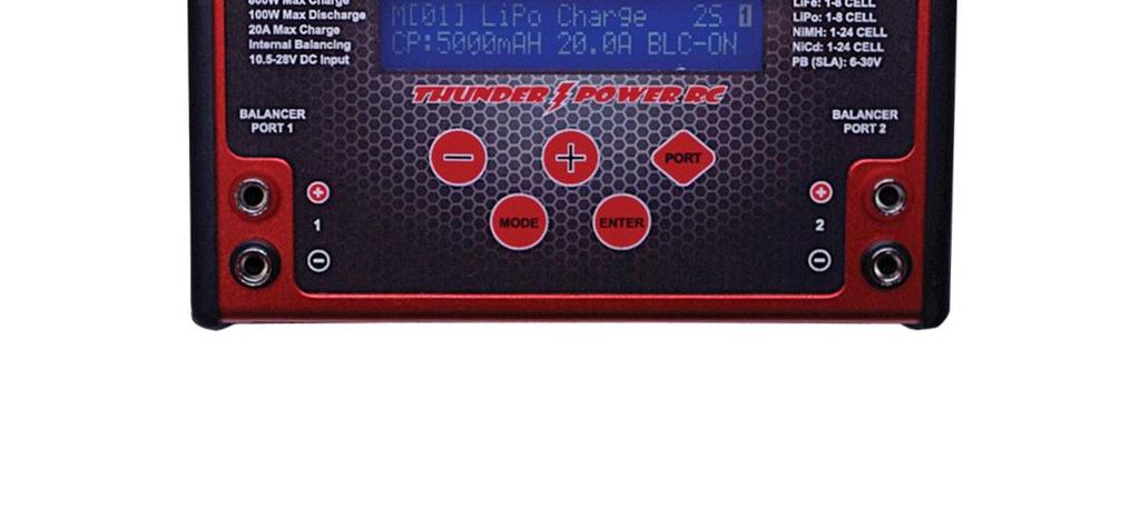
11 OPERATING INFO Button Functions +/ buttons The +/ buttons allow you to scroll up/down through menus before and during charging/discharging. These buttons also allow you to change values/settings for options after they have been selected (typically when flashing after pressing the ENTER button). PORT button The PORT button allows you to toggle/switch the port (1 or 2) you are currently viewing. You can toggle/switch between each port any time before and during charging/discharging by pressing the PORT button. Also, the port you are currently viewing is always indicated by a 1 or 2 as seen in the upper right hand corner on all screens. MODE button The MODE button functions only before/when not charging/discharging. Pressing the MODE button will allow you to scroll between the three available modes: Charge/Discharge/Cycle/Storage Modes Setting Data Mode Data View Mode ENTER button The ENTER button allows you to select and validate values/settings for options that can be changed (using the +/ buttons to change) before and during charging/discharging. Pressing and holding the ENTER button also allows you to start and stop charging/discharging. CHARGE MODE After powering on the charger properly the first mode always shown by default is the Charge Mode. This is the mode that allows you to set the memory profile number, battery chemistry type, number of cells, battery capacity limit, charge current rate, balancing on/off for LiPo/LiIon/Life or the delta peak value for NiCd/NiMH. It s also important to note that all of these settings must be set in this mode/screen before changing to the discharge, cycle or storage modes (these settings cannot be changed/set in those modes). Here is a quick reference of what the Charge Mode screen displays: ) Memory profile number 2) Battery chemistry type 3) Mode (charge, discharge, cycle, storage) 4) Number of cells (in series) 5) Port currently being viewed 6) Battery capacity 7) Current rate 8) Balancing ON/OFF for LiPo/LiIon/LiFe or Delta Peak Sensitivity value for NiCd/NiMH
12 Memory Profiles You can set a total of 12 memory profiles per port (24 total). This is a convenient feature as it allows you to set the typical charge, discharge, cycle and storage mode profiles for specific batteries to save you time versus having to always change the settings when charging/discharging different configurations and chemistries of batteries. To scroll through the available memory profiles, while on the Charge Mode screen simply press the ENTER button once. The memory profile number will begin to flash and you can use the +/ buttons to scroll through the profiles accordingly. And again, you can set up to 12 profiles per port (24 profiles in total), however, we do recommend setting the same profiles, in the same order, for both ports if you have no more than 12 different configurations/chemistries of batteries as it will allow you to select the profile for your batteries on either or both ports simultaneously with ease. Battery Chemistry Type The TP820CD is capable of charging/discharging LiPo, LiIon, LiFe (A123), NiCd, NiMH and Pb (leadacid) batteries. Each of these chemistries/types of batteries is charged in a different way and you MUST select the correct chemistry/type in order for the charger to charge/discharge safely. Failure to select the correct chemistry/type and settings per the battery being charged/discharged can result in damage to the battery or fire causing damage and/or personal injury. If you are unsure of the battery chemistry/type, and the correct settings that must be used for safe and correct charging/discharging, DO NOT attempt to charge/discharge the battery. Instead, please contact the manufacturer of the battery for more information first. To select the correct battery chemistry/type, while on the Charge Mode screen simply press the ENTER button twice. The battery chemistry/type will begin to flash and you can use the +/ buttons to scroll through them accordingly. After selecting the correct chemistry/type you can press the ENTER button to select the other adjustable values, or wait approximately 5 seconds until the chemistry/type stops flashing to begin the charge process or to scroll through the other modes (discharge, cycle and storage). Battery Cell Count The TP820CD is capable of charging/discharging 1S (3.7V) to 8S (29.6V) LiPo, LiIon and LiFe (A123) batteries, as well as 1-24 cell NiCd and NiMH along with 1S (2V) to 15S (30V) Pb (lead-acid) batteries. After selecting the correct battery chemistry/type you MUST select the correct cell count for the battery you will be charging/discharging. Failure to select the correct cell count per the battery being charged/discharged can result in damage to the battery or fire causing damage and/or personal injury. If you are unsure of the battery cell count DO NOT attempt to charge/discharge the battery. Instead, please contact the manufacturer of the battery for more information first. To select the correct battery cell count, while on the Charge Mode screen simply press the ENTER button three times. The battery cell count will begin to flash and you can use the +/ buttons to increase/decrease the cell count accordingly. After selecting the correct cell count you can press the ENTER button to select the other adjustable values, or wait approximately 5 seconds until the cell count stops flashing to begin the charge process or to scroll through the other modes. 12
13 Battery Capacity For added safety and ease of use, the TP820CD features a function that allows you to set the battery capacity. This function allows you to enter the capacity of the battery you ll be charging so the charger can automatically set a 1C (1 x Capacity) charge rate. In general most supported battery chemistries/types can be charged safely and successfully at a 1C rate so this feature makes for the easiest possible setting and use especially if you are not confident in taking advantage of and/or aware of the max charge rate capability of the battery you ll be charging. This function also adds an additional level of safety as it helps to ensure, in conjunction with the CHG (Charge) Capacity Limit function found in the Setting Data (Settings) menu, that even if the charger does not terminate/end charging correctly per the battery chemistry/type, that it will still end the charge when the set capacity has been reached. These details in mind you should ALWAYS set the battery capacity correctly. To set the correct battery capacity, while on the Charge Mode screen simply press the ENTER button four times. The battery capacity will begin to flash and you can use the +/ buttons to increase/decrease the capacity accordingly. After setting the correct capacity you can press the ENTER button to select the other adjustable values, or wait approximately 5 seconds until the cell count stops flashing to begin the charge process or to scroll through the other modes. Charge Current Rate After setting the battery capacity limit correctly, the charger will automatically set the charge current rate to 1C. In the case of a 5000mAh battery, it will set the charge current to 5.00A. And again, in general most supported battery chemistries/types can be charged safely and successfully at a 1C rate so we suggest charging at the 1C rate especially if you are not confident in taking advantage of and/or aware of the max charge rate capability of the battery you ll be charging. Or, if you are interested in charging at a rate higher (or lower) than 1C you can adjust the charge current rate accordingly. However, it is important to note that if you charge at a current rate that is too high it can result in damage to the battery or even fire causing damage and/or personal injury. If you are unsure of the maximum safe charge rate of the battery DO NOT charge at a rate higher than 1C or please contact the manufacturer of the battery for more information. And to set the charge current rate, while on the Charge Mode screen simply press the ENTER button five times. The charge current rate will begin to flash and you can use the +/ buttons to increase/decrease the current rate accordingly. After setting the charge current rate per your preference you can press the ENTER button to select the other adjustable values, or wait approximately 5 seconds until the current rate stops flashing to begin the charge process or to scroll through the other modes. Also, before starting the charge process the maximum charge current that can be set (if it is less than 20.0A, which is the max charge current rate for each port) is automatically calculated by the charger based on the voltage of the input power source and the estimated voltage of the battery being charged based on the cell count you have selected. This is calculated using the discharged voltage of the battery (i.e. ~3.3V per cell for LiPo batteries) so it is possible to set the charge current rate to the maximum rate possible. And if you have set the charge current rate to the maximum rate possible, after starting the charge process the charger will automatically adjust the current rate, per the actual voltage of the battery at any given time, to maintain (and not exceed) the maximum output power level (wattage). For example, in the case of charging a 6S 22.2V 5000mAh LiPo battery and when using a 13
14 V/35-40A power supply for maximum input/output power, before the charge process has started you will be able to set the charge current rate to 20.0A max. However, if the battery is currently at more than 20.0V the charger will then adjust the current rate automatically between 20.0A and approximately 15.8A as needed to ensure it does not exceed the 400W maximum output power level of each port. And when the battery nears/reaches the end of the Constant Current (CC) phase of the charge around 25.2V (4.2V per cell) the current rate will reduce accordingly throughout the Constant Voltage (CV) phase of the charge process and until the charge is complete. Also, after the charge process has started (and if you have not already set the charge current rate to the maximum rate possible) you can actually increase the charge current rate by up to 25% (i.e. from 10.0A to 12.5A) or to the maximum charge current rate possible based on the actual voltage of the battery and power level of each port; whichever comes first. To do this, simply press the ENTER button once immediately (or any time) after the charge process has been started (and the Battery Check Please Wait check is complete) and the current rate will begin to flash. You can then use the + button to increase (or the button to decrease) the current rate accordingly. These details in mind, please also see the chart provided separately for a quick reference of the maximum output power levels/charge current rate settings for LiPo batteries based on the listed input voltage and current (and please note that these values are approximate and may vary +/- slightly depending on the input voltage, output current, power level of the power source under load, ambient temperatures, state of charge/voltage level of the battery being charged, etc.). Balancing ON/OFF (for LiPo/LiIon/LiFe batteries) As noted in further detail in the BALANCER CONNECTIONS section of this manual, the TP820CD is equipped with built-in balancers for LiPo/LiIon/LiFe (A123) cells/batteries and you should ALWAYS use the balancers when charging LiPo/LiIon/LiFe batteries for maximum safety and battery performance/longevity. The balancers, working in conjunction with the charger, perform functions similar to the safety circuits found in the LiPo/LiIon/LiFe cells/batteries for cell phones, laptop and other electronic devices to prevent over-charging that can result in fire causing damage and/or personal injury. They do this by ensuring the voltages of cells within LiPo/LiIon/LiFe batteries are closely equalized/balanced by discharging the higher voltage cells to closely match the lower voltage cell(s) in the battery. This prevents over-charging any cell(s) that may have a higher voltage during the charge process, or, in the event that the balancer cannot balance the cell(s) in time to prevent exceeding the CHG End Voltage setting (for any cell), the charger will automatically reduce the charge current rate and/or end the charge process entirely as needed. The balancers can also further ensure that you ve set the cell count correctly, and as a result we strongly recommend keeping the balancing turned ON at all times. Please also note that when balancing is turned ON you MUST connect the balance connector of the battery to the balance connector adapter board (which must be connected to the balancer/charger) BEFORE you start the charge process otherwise you ll encounter a Battery Type Error warning. However, if you understand the associated risks, accept full responsibility and choose to charge LiPo/LiIon/LiFe batteries without balancing/using the built-in balancers, it is possible to turn the balancing OFF. To turn the balancing ON/OFF, while on the Charge Mode screen simply press the ENTER button six times. The balancing status will begin to flash and you can use the +/ buttons to turn it ON or OFF. After turning the balancing ON or OFF per your preference you can press the ENTER button to select the other adjustable values, or wait approximately 5 seconds until the status stops flashing to begin the charge process or to scroll through the other modes. 14
15 Delta Peak Sensitivity (for NiCd/NiMH batteries) When the charger has been set to charge NiCd or NiMH chemistry/type batteries you can also set the delta peak sensitivity value. This is the difference in voltage when the NiCd/NiMH battery reaches peak voltage/fully charged voltage and is used to complete/end charging of NiCd/NiMH batteries accordingly. Generally speaking a higher delta peak sensitivity value will result in more charge or even potential over-charge, however, in many cases a slight amount of over-charge and the resulting warming of the cells/battery is desired to ensure the highest possible performance. Slightly warm cells/batteries (approximately 5-15 Fahrenheit above ambient) are also a good indication that they are fully charged, however, it is recommended to use the lowest delta peak sensitivity value that allows the cells/battery to be fully charged and to not stop charging prematurely (typically referred to as false peaking ). NiCd cells/batteries typically require a higher delta peak sensitivity value (~10-20mV per cell) to reach full charge while NiMH batteries require a lower value (~1-10mV per cell). However, in the case of either chemistry the actual value that works best will depend on many factors including the capacity, condition and internal resistance (IR) of the cells/battery, IR of the charge leads/connectors, charge current rate, ambient temperature and more. As a result it is always suggested to start with a lower value and to increase the value accordingly as needed to achieve slight warming of the cells after the charge process had been completed/ended. To adjust the delta peak sensitivity value, while on the Charge Mode screen simply press the ENTER button six times. The value will begin to flash and you can use the +/ buttons to increase or decrease the value accordingly. After setting the value per your preference you can press the ENTER button to select the other adjustable values, or wait approximately 5 seconds until the value stops flashing to begin the charge process or to scroll through the other modes. Charging the Battery After setting the correct battery chemistry type, cell count, capacity and current, and connecting the battery to the charger properly, you are ready to begin charging. To begin charging simply press and HOLD the ENTER button for a few seconds (please also note that during charging you can press and hold the ENTER button to end the charge process). From there the charger will check the battery while displaying the following screen: If the battery is connected properly and the charger confirms that all other parameters are correct, charging will begin automatically. Charging LiPo/LiIon/LiFe (A123) Batteries When charging LiPo/LiIon/LiFe batteries, if the voltage of any cell (when balancing is ON) or all cells are too low (below ~3.3V) the charger may charge at a rate lower than the charge current rate set before the charge process began and until the voltage is considered safe/high enough to charge the battery normally. Or, if the voltages of all cells are OK the charger will increase the current until it reaches the appropriate charge current rate. And in either case charging will be in the Constant Current phase, as indicated by the CC located in the middle of the upper line on the screen, until the cells reach approximately 4.20V. 15
16 At that point, and as long as cells are balanced within 0.03V (when balancing is ON), charging will switch to the Constant Voltage phase as indicated by the CV that will show in placed of CC. Or, if any cell is imbalanced by more than 0.03V charging will instead switch from the Constant Current phase to the Extended Balance phase, as indicated by the EB that will show in place of CC/CV. This will allow the charger to adjust the charge current rate as needed to ensure the cells are balanced to within 0.03V (or closer) before the charge process is ended automatically. Data Monitoring During Charging Throughout (and after) the charge process you can view/monitor various data. On the main charging screen you will see the elapsed duration of the charge process, the capacity that s been charged into the battery, the charge current rate and the voltage of the battery. You can also use the +/ buttons to switch between the various screens to see the available data. For example, when charging a LiPo/LiIon/LiFe battery and on the charging screen simply press the + button once and you will see the individual cell voltages (when balancing is turned ON). Please also note that while only the second (hundredths) place after the decimal is shown due to the space available on the screen (in order to show voltages for up to 8 cells on a single screen), the charger is measuring and calculating the voltages/balance by using to the third (thousandths) place. This means when you see a cell at 3.80V and another at 3.82V the cells are likely as close as 3.804V and 3.816V but the values on the screen are being rounded up and down accordingly. If you press the + button a second time you ll again see the elapsed time, as well as the internal temperature of the charger and the peak voltage the battery has reached through the duration of the charge process so far. Then, pressing the + button a third time will show the elapsed time along with the input voltage from the power source. This can be particularly useful, especially when pushing the input power source near its limits and/or when using a 12V (or 24V) Pb/lead-acid battery, to ensure the voltage is not dropping too much when under load during the charging process. Please also note that while only the second (hundredths) place after the decimal is shown the charger is measuring and calculating the input voltage by using to the third (thousandths) place. This means the input voltage reading may appear to move up and down slightly, however, as long as it is not fluctuating by more than ~0.03V the input voltage/power is indeed smooth and stable. And when charging a NiCd/NiMH/Pb (lead-acid) battery, the first time you press the + button you will again see the elapsed time along with the average voltage of the battery that would show after a discharge process has ended. Pressing the + button a second time will also show the internal temperature of the charger and the peak voltage the battery reached during the charge process while pressing the + button a third time will show the elapsed time along with the input voltage from the power source. Charging Complete/End Charging will be complete/end automatically when the battery capacity has been reached, per delta peak (for NiCd/NiMH batteries) or when the appropriate per cell CHG (Charge) End Voltage has been reached (for LiPo/LiIon/LiFe and Pb batteries). When this occurs you will see the following screen: 16
17 From there you can press the ENTER button once to display the data from the charge process, as well as use the +/ buttons to scroll through other screens, including the screen that features the Battery.IR function to check the Internal Resistance (IR) of the battery and/or individual cells by pressing the ENTER button (while on those screens). Or, on most other screens you can press the ENTER button to exit the charge process completely. Charging LiPo Batteries for use in Series on Separate Ports The dual port flexibility and convenience of the TP820CD makes it an excellent choice for charging LiPo batteries up to 8S 29.6V separately on each port for use in series up to 16S 59.2V in large-scale airplanes, helicopters and other applications. Other popular examples include charging 5S and 6S mAh batteries for use in series as 10S and 12S setups in F3A, F3C and 3D helicopter applications at rates up to 4C for charge times of as little as 15 minutes or less. Charging each battery that will be used in series separately on each port is quick and easy to do. Simply connect one battery to each port and set them to charge at the same rates. And while in some cases there may be slight variations in the time it takes to charge each battery (meaning one may finish charging before the other), because the two ports are calibrated very closely, the batteries should be charged to almost exactly the same level which can also save substantial time over having the two ports attempt to charge/balance together simultaneously. Also, due to potentially slight differences in the condition/performance of each battery, we suggest checking to ensure that both batteries are charged to within approximately 0.05V (or less) after the charge process is complete for each. From there the batteries are ready to use in series, and we suggest, as with all LiPo batteries, to discharge no more than 80-85% capacity to ensure maximum performance and longevity. Charging Split LiPo Batteries up to 16S on Separate Ports The dual ports of the TP820CD are also an excellent choice for charging split batteries that feature interconnect leads (for transport/shipping as non-dangerous/non-hazardous goods when the leads are left disconnected) up to 16S 59.2V. The split/interconnect configuration of most of these batteries allows them to be charged as two lower cell count batteries. For example an appropriately configured 10S split battery with interconnect leads, such as all Thunder Power RC G4 and G6 10S mAh batteries, can be charged as two separate 5S batteries. And in the case of 10S 5000mAh split batteries in particular, you can charge each 5S half on each port at rates up to 4C for charge times of as little as 15 minutes or less for the complete 10S battery. Using the dual ports of the TP820CD to charge split batteries requires only a few additional accessories and setup steps to make it relatively quick and easy. And using a Thunder Power RC 10S 5000mAh battery equipped with the factory-installed 4mm bullet connectors on the interconnect leads and a female Deans Ultra Plug connector on the main power leads as an example, the following accessories are required (as shown in the photo below): AWG charge lead with a male Deans Ultra Plug connector; 1pc AWG negative charge lead with a male 4mm bullet connector on both ends; 1pc AWG positive charge lead with a male 4mm bullet connector on one end and a female 4mm bullet connector on the other end; 1pc TP6P10E (6-Pin Balance Connector Extension w/10" Color Coded Wires); 2pcs (OPTIONAL) 17


 to the 4-5S Thunder Power connector on each board (this step is")
.")


18 Beginning with the charge lead equipped with a male Deans connector, connect the negative lead to the negative female banana plug receptacle of port 1. Then connect the positive lead to the positive female banana plug receptacle of port 2. Next, connect the male end of the separate positive lead to port 1 and one of the male ends of the separate negative lead to port 2 as shown in the photo. With a balance connector adapter board connected to each balancer port on the charger, connect 1pc of TP6P10E (6-Pin Balance Connector Extension w/10" Color Coded Wires) to the 4-5S Thunder Power connector on each board (this step is optional as you can also connect the balance connector leads from the battery directly to the adapter boards, however, the relatively short lead lengths can make this somewhat difficult). Now the most important step is to ensure that the balance connector labeled as Group A on the battery is connected to the extension/balance connector adapter board connected to port 1 (this is because the main negative/ground wire lead from the battery is also connected to port 1). Then connect the balance connector labeled as Group B to the extension/balance connector adapter board connected to port 2. The battery is now connected to the charger properly and ready to be charged (and please note that if you mix up the balance connector connections per port it should not damage the battery/charger, however, it will result in an error when attempting to charge with either port because the port will see the main power leads and balance connector leads from two different halves of the battery). See the photo for reference of the correct connection/wiring arrangement including the battery. 18
19 Now you will need to configure each port to charge a 5S LiPo battery at the charge current rate of your preference. We suggest configuring one of the ports correctly, then moving to the second port to configure it correctly. Then start the charging process on the last port you configured then switch to the other port and start the charge process accordingly. And while in some cases there may be slight variations in the time it takes to charge each half of the battery (meaning one may finish charging before the other), because the two ports are calibrated very closely, the halves should be charged to almost exactly the same level which can actually save substantial time over having the two ports attempt to charge/balance the halves together simultaneously. Also, due to potentially slight differences in the condition/performance of each battery, we suggest checking to ensure that both halves are charged to within approximately 0.05V (or less) after the charge process is complete for each. From there the battery is ready to use as 10S (after connecting the interconnect leads), and we suggest, as with all LiPo batteries, to discharge no more than 80-85% capacity to ensure maximum performance and longevity. DISCHARGE MODE The TP820CD is able to discharge batteries in order to check capacity or for other reasons as needed. It s capable of discharging at rates up to 10.0A and 50W per port, and keep in mind that aside from the discharge current rate and per cell voltage cutoff that can be set in the Discharge Mode, the cell count must be set in the Charge Mode. 19
20 After setting the correct cell count in the Charge Mode, wait until none of the adjustable values are flashing, then press the + button once to enter the Discharge Mode. Discharge Current Rate In general most supported battery chemistries/types can be discharged safely and successfully at a 1C to 4C rate so we suggest discharging at no higher than these rates especially if you are not aware of the max discharge rate capability of the battery you ll be discharging. That said, because the TP820CD is capable of discharging at rates up to 10A/50W, in many cases it will not be possible to discharge batteries, especially those above approximately 3S 11.1V 5000mAh, at even a 1C rate. However, especially in the case of lower capacity batteries for which you can exceed a 4C discharge rate, it is important to note that if you discharge at a current rate that is too high it can result in damage to the battery or even fire causing damage and/or personal injury. If you are unsure of the maximum safe discharge rate of the battery DO NOT discharge at a rate higher than 1C to 4C or please contact the manufacturer of the battery for more information. And to set the discharge current rate, while on the Discharge Mode screen simply press the ENTER button once. The discharge current rate will begin to flash and you can use the +/ buttons to increase/decrease the current rate accordingly. After setting the discharge current rate per your preference you can press the ENTER button to select the other adjustable values, or wait approximately 5 seconds until the current rate stops flashing to begin the discharge process or to scroll through the other modes. Also, before starting the discharge process the maximum discharge current that can be set (if it is less than 10.0A, which is the max discharge current rate for each port) is automatically calculated by the charger based on the estimated voltage of the battery being discharged and the cell count you have selected (~3.6V per cell for LiPo batteries). So in most cases it is not possible to set the discharge current rate to the 10.0A max for cell counts more than 1S 3.7V for LiPo/LiIon/LiFe, and even if you do set the rate to 10.0A for higher cell batteries, it will exceed the maximum discharge power level (wattage) capabilities of each port and the charger will reduce the rate accordingly after the discharge process has started. And after the discharge process has started you can actually increase the discharge current rate by up to 25% (i.e. from 5.00A to 6.25A) or the maximum discharge current rate possible based on the actual voltage of the battery and power level of each port; whichever comes first. To do this, simply press the ENTER button once immediately (or any time) after the discharge process has been started (and the Battery Check Please Wait check is complete) and the current rate will begin to flash. You can then use the + button to increase (or the button to decrease) the current rate accordingly. And in the event that the discharge current rate and voltage of the battery being discharged, as well as the ambient temperature and internal temperature of charger, result in over-heating the charger (above ~130 F) during the discharge process, you will see the Over Temperature Please Wait 000 warning including the current internal temperature of the charger. The charger will automatically pause the discharge until it cools to approximately 100 F, then it will resume the discharge automatically. And although the discharge current rate and voltage of the battery may not exceed the maximum discharge power rating of the port, especially in the case of higher capacity batteries that take longer to discharge and create more heat in the charger for a longer period of time, you may indeed need to reduce the discharge current rate in order to prevent the over temperature and pause. 20
21 These details in mind, please also see the chart provided separately for a quick reference of the estimated maximum discharge power levels/discharge current rate settings for LiPo batteries based on the current rate and estimated voltage of the battery (and please note that these values are approximate and may vary +/- slightly depending on ambient temperatures, state of charge/voltage level of the battery being discharged, etc.). Discharge Voltage Cutoff You can set the per cell voltage cutoff that will complete/end the discharge process automatically using this setting. However, especially in the case of LiPo/LiIon/LiFe batteries, it is important that you DO NOT over-discharge the batteries to a voltage that is too low as it can result in damage to the battery. If you are unsure of the safest discharge voltage cutoff for the battery DO NOT discharge the battery or please contact the manufacturer of the battery for more information. Here also are some general suggestions of the per cell voltage cutoff to use for each battery chemistry/type to prevent over-discharge/damage: LiPo/LiIon V per cell when discharged at rates of 1-4C LiFe V per cell when discharged at rates of 1-4C NiCd/NiMH V per cell when discharged at rates of 1-4C Pb/lead-acid V per cell when discharged at rates of 1-4C Discharging the Battery After setting the correct battery chemistry type and cell count in the Charge Mode, then also the correct discharge current rate and voltage cutoff in the Discharge Mode, connect the battery to the charger properly and you are ready to begin discharging. To begin discharging simply press and HOLD the ENTER button for a few seconds (please also note that during discharging you can press and hold the ENTER button to end the discharge process). From there the charger will check the battery while displaying the following screen: If the battery is connected properly and the charger confirms that all other parameters are correct, discharging will begin automatically. Data Monitoring During Discharging Throughout (and after) the discharge process you can view/monitor various data. On the main discharging screen you will see the elapsed duration of the discharge process, the capacity that s been discharged from the battery, the discharge current rate and the voltage of the battery. You can also use the +/ buttons to switch between the various screens to see the available data. For example, when discharging a LiPo/LiIon/LiFe battery and on the discharging screen simply press the + button once and you will see the individual cell voltages (when balancing is turned ON). If you press the + button a second time you ll again see the elapsed time, as well as the internal temperature of the charger and the peak voltage of the battery at the beginning of the discharge process. Pressing the + button a third time will show the elapsed time in addition to the input voltage from the power source. 21
22 And when discharging a NiCd/NiMH/Pb (lead-acid) battery, the first time you press the + button you will again see the elapsed time along with the average voltage of the battery that will be shown when the discharge process has ended. Pressing the + button a second time will also show the internal temperature of the charger and the peak voltage of the battery at the beginning of the discharge process while pressing the + button a third time will show the elapsed time in addition to the input voltage from the power source. Discharging Complete/End Discharging will be complete/end automatically when the battery reaches the appropriate per cell voltage. When this occurs you will see the following screen: From there you can press the ENTER button once to display the data from the discharge process, as well as use the +/ buttons to scroll through other screens, including the screen that features Battery.IR to check the Internal Resistance (IR) of the battery and/or individual cells (for LiPo/LiIon/LiFe and with the balancer connected) by pressing the ENTER button while on that screen. Or, on most other screens you can press the ENTER button to exit the charge process completely. Cooling Fans During/After Discharge During the discharge process one or both fans may come on at low or high settings to help control the internal temperature of the charger. In some cases, even after the discharge process has completed/ended the fans will continue to run even when the internal temp has reached near ambient temperature. If this happens you can power the charger off then on again and the fans will remain off until the next charge/discharge process begins (and only if needed). Please also note that there are plans to offer enhanced fan control and the ability to set temperature cutoffs in future firmware releases. CYCLE MODE The TP820CD is capable of charging/discharging batteries automatically by cycling them up to 15 times. This can be particularly useful for testing and/or rejuvenating NiCd/NiMH batteries and please note that we DO NOT recommend cycling LiPo/LiIon/LiFe batteries as it comes at great risk unless you monitor all charge/discharge cycles in person fully and set the discharge cutoff voltage to a level high enough to prevent over-discharge. Even still it has been shown that, unlike other chemistries such as NiCd/NiMH, it is typically not possible to rejuvenate LiPo/LiIon/LiFe cells/batteries through charge/discharge cycling. Please also keep in mind that aside from selecting the order of charge->discharge (CHG->DCHG) or discharge->charge (DCHG->CHG) and the number of cycles, you must set the chemistry type, cell count, capacity and charge current rate in the Charge Mode, and the discharge current rate and the per cell voltage cutoff in the Discharge Mode. After setting the correct values in the Charge Mode, wait until none of the adjustable values are flashing, then press the + button once to enter the Discharge Mode. After setting the correct values in this mode, wait until none of the values are flashing then press the + button one more time to enter the Cycle Mode. 22
23 Cycle Order You can select the cycle order, charge->discharge (CHG->DCHG) or discharge->charge (DCHG- >CHG), using this setting. To change the order simply press the ENTER button once then use the +/ buttons to adjust the order accordingly. Cycle Number This allows you to set the number of cycles the charger will automatically perform from 1 to 15. To set the number simply press the ENTER button twice and use the +/ buttons to adjust the number of cycles accordingly. Cycling the Battery After setting the correct battery chemistry type, cell count, capacity and charge current rate in the Charge Mode, and the correct discharge current rate and voltage cutoff in the Discharge Mode along with the cycle order and number of cycles, you are ready to begin cycling. To begin cycling simply press and HOLD the ENTER button for a few seconds (please also note that during cycling you can press and hold the ENTER button to end the charge process). From there the charger will check the battery while displaying the following screen: If the battery is connected properly and the charger confirms that all other parameters are correct, cycling will begin automatically. Data Monitoring During Cycling Throughout (and after) the cycling process you can view/monitor various data. On the main cycling screen you will see the elapsed duration of the current charge or discharge process, the capacity that s been charged into/discharged from the battery, the charge/discharge current rate and the voltage of the battery. Also, it will be possible to identify whether the charger is charging or discharging for the current cycle, as well as the number of the current cycle, by looking at the C00D info located in the middle of the upper line on the screen. When the C is flashing the charger is charging, and when the D is flashing the charger is discharging. And the number of the current cycle, 01 through 15, will be displayed between the C and D accordingly. You can also use the +/ buttons to switch between the various screens to see the other available data. For example, when cycling a NiCd/NiMH battery, the first time you press the + button you will again see the elapsed time along with the average voltage of the battery that will be shown when the discharge process has ended. Pressing the + button a second time will also show the internal temperature of the charger and the peak voltage of the battery during the charge or at the beginning of the discharge process. Cycling Complete/End Discharging will be complete/end automatically when the battery reaches the appropriate per cell voltage. When this occurs you will see the following screen: 23
24 From there you can press the ENTER button once to display the data from the cycling process, as well as use the +/ buttons to scroll through other screens, and on most other screens you can press the ENTER button to exit the charge process completely. It s also important to note that the data from the completed cycling process can also be viewed in the Data View mode after exiting the process and before the next charge/discharge process begins. STORAGE MODE The TP820CD features an advanced Storage Mode that automatically discharges and/or charges the battery for safe and healthy storage. For added reference you should NEVER store LiPo batteries at full charge for more than few hours at most (and they should be stored at temps of F whenever possible to prevent swelling and/or loss of performance/capacity). Instead you should use the Storage Mode to automatically charge or discharge them to approximately 50% capacity (~3.85V per cell), especially if the battery is more than 50% charged and will not be used in the next few hours. Please also keep in mind that you must set the chemistry type, cell count, capacity and charge current rate in the Charge Mode and the discharge current rate in the Discharge Mode. These are the values used by the charger to automatically charge/discharge the battery accordingly in the Storage Mode. In the case of LiPo/LiIon batteries, the charger will automatically charge (if the voltage is below approximately 3.85V per cell) or discharge (if the voltage is above approximately 3.85V per cell) the battery to approximately 3.85V per cell, and for LiFe batteries to approximately 3.3V per cell. For NiCd/NiMH batteries the charger will automatically discharge them to the discharge voltage cutoff set in the Discharge Mode, then charge them to 50% of the capacity set in the Charge Mode. Storage Charging/Discharging the Battery After setting the correct battery chemistry type, cell count, capacity (for NiCd/NiMH batteries) and charge current rate in the Charge Mode, and the correct discharge current rate and voltage cutoff (for NiCd/NiMH batteries) in the Discharge Mode, you can begin the storage process by simply pressing and HOLDING the ENTER button for a few seconds (please also note that during the storage process you can press and hold the ENTER button to end the process accordingly). From there the charger will check the battery while displaying the following screen: If the battery is connected properly and the charger confirms that all other parameters are correct, the storage process will begin automatically. Data Monitoring During the Storage Process Throughout (and after) the storage process you can view/monitor various data. On the main storage screen you will see the elapsed duration of the current charge or discharge process, the capacity that s been charged into/discharged from the battery, the charge/discharge current rate and the voltage of the battery. Also, it will be possible to identify whether the charger is charging or discharging by looking at the CHG or DCHG info located in the middle of the upper line on the screen. When CHG shows the charger is charging, and when DCHG shows the charger is discharging. 24
25 You can also use the +/ buttons to switch between the various screens to see the other available data. For example, when in the storage process for a LiPo/LiIon/LiFe battery simply press the + button once and you will see the individual cell voltages (when balancing is turned ON). And if you press the + button a second time you ll again see the elapsed time, as well as the internal temperature of the charger and the peak voltage of the battery during the charge or at the beginning of the discharge process. And when in the storage process for a NiCd/NiMH battery, the first time you press the + button you will again see the elapsed time along with the average voltage of the battery that will be shown when the discharge process has ended. Pressing the + button a second time will also show the internal temperature of the charger and the peak voltage of the battery during the charge or at the beginning of the discharge process. Storage Complete/End Storage will be complete/end automatically when the battery reaches the appropriate per cell voltage or capacity. When this occurs you will see the following screen: From there you can press the ENTER button once to display the data from the storage process, as well as use the +/ buttons to scroll through other screens, and on most screens you can press the ENTER button to exit the storage process completely. SETTING DATA (SETTINGS) MODE The Setting Data mode of the TP820CD allows you to set the various default settings/data for a variety of functions. You can reach the Setting Data mode from any of the Charge, Discharge, Cycle or Storage Mode screens by pressing the MODE button once. From there you can use the +/ buttons to scroll through the available screens/menus accordingly. It s also important to note that the follow settings/data apply the same to both ports (and all memory profiles) and can be viewed/changed when either port is selected: Power Distribution, Input Power LVC, Input Current MAX and Temperature Unit. All other settings/data apply to each port (and in some cases the memory profile too) individually and must be viewed/changed according to the specific port. Charge End Voltage The..CHG End Voltage sets the end voltage per cell the charger will achieve before completing/ending the charge process. This value can be set for all chemistry types, however, you must have the chemistry you would like to set the value for selected in the Charge Mode in order for that chemistry to show appropriately in the charge end voltage screen/menu. It s also important to note that the charge end voltage value can be set PER MEMORY PROFILE so you can fine-tune the end voltage of the battery, just as you can the chemistry type, capacity and charge current rate. This is helpful because sometimes batteries of the same cell count and capacity, but different internal resistance/performance levels, may charge to slightly different end voltages when using the same charge end voltage value. In those cases it may be helpful to have the same chemistry type, cell count, capacity and charge current rate values but different charge end voltage values in two different memory profiles. To adjust this value simply press the ENTER button once and the value will flash. Then use the +/ buttons to increase/decrease the value per your preference and/or the guidelines listed below. 25
26 For LiPo batteries, and LiIon batteries with a nominal voltage of 3.7V per cell (and full charge voltage of 4.2V per cell), you can set the charge end voltage up to 4.24V per cell. And although the maximum recommended charge end voltage per cell is 4.235V, due to slight variations in the components and calibration of each charger, resistance of charge leads and cells/batteries, ambient conditions and more, it is possible that when the value is set to 4.24V it will not actually exceed 4.235V per cell when checked with a calibrated Digital Volt Meter (DVM). We first recommend charging with the value set to 4.20V per cell then checking the actual voltage per cell with a calibrated DVM (DO NOT use a non-calibrated DVM for this check as it can read the voltage too high or too low and cause you to adjust the value incorrectly). If the voltage of each cell is between 4.19V and 4.21V, we suggest leaving the setting as is. Or, if the voltage is even higher or lower you can adjust the value +/ 0.01V and test again until you achieve the desired charge end voltage for your particular charger and batteries (and again, this is adjusted independently per port and per memory profile for each port). Please note that this adjustment is to allow for advanced fine-tuning/calibration of the charge end voltage, however, if you do not have a calibrated DVM and/or experience with this type of checking and tuning we suggest leaving the value at 4.20V per cell regardless. For LiIon batteries with a nominal voltage of 3.6V per cell, or if you d like to charge your LiPo batteries to approximately 90% charged in order to extend their cycle life and shorten charge times, typically the recommended full charge voltage is 4.1V per cell. This in mind you can use the LiPo Charge Mode and charge end voltage setting, adjusted to 4.10V, to charge the appropriate LiIon batteries (or LiPo batteries to approximately 90% charged) accordingly. LiFe batteries typically have a recommended full charge voltage of 3.60V per cell. However, you can set the charge end voltage up to 3.80V per cell for the same reasons as noted for LiPo batteries above. Also, please note that this adjustment is to allow for advanced fine-tuning/calibration of the charge end voltage, however, if you do not have a calibrated DMV and/or experience with this type of checking and tuning we suggest leaving the value at 3.60V per cell regardless. For Pb/Lead-acid batteries, we suggest setting the charge end voltage to the value per cell recommended by the battery manufacturer (as these values do vary from manufacturer to manufacturer). However, a value of approximately V per cell (~ V for a typical 6S 12V battery) is typically a safe, conservative value for all Pb/lead-acid batteries. For NiCd/NiMH batteries you will typically use the Delta Peak Sensitivity value, set in the Charge Mode, to ensure proper peak/full charging of the batteries accordingly. However, in case you set the delta peak sensitivity value too high, you can also set the charge end voltage to complete/finish the charge process instead. In this case we suggest setting the charge end voltage value to V per cell because if the value is set too low it will not allow for proper peak/full charging of the batteries. Power Distribution When using an input power source that is only capable of supplying less current than the 40A required for maximum power (wattage) output per a given input voltage you can adjust the distribution of power between the ports to achieve up to max power from a single port (as the actual input voltage and current allow) rather than splitting it evenly and between both ports (as is the case with the default setting of 50% and 50%). For example, with an input power source that supplies 12V and 30A max under load, if the Power Distribution is set to 50% and 50%, the maximum wattage available from each port will be approximately 150W max (300W total). However, because each port is capable of up to 250W max with 12V input, you can actually bias the power distribution to give one port more power versus the other in order to achieve the 250W max for one and 50W for the other (achieving the same 300W total but with more/max output power capability for one of the ports). This is particularly useful if you need 26
27 to charge higher capacity/cell count motor power batteries on one port and lower capacity/cell count motor power, receiver, transmitter, etc. batteries on the other port simultaneously. You can adjust the power distribution levels by pressing the ENTER button once and using the +/ buttons to adjust the levels accordingly. And please also see the chart provided separately for a quick reference of the maximum output power levels/charge current for LiPo batteries based on the listed input voltage and current (and please note that these values are approximate and may vary +/ slightly depending on input voltage of the power source under load, ambient temperatures, state of charge/voltage level of the battery being charged, etc.). Input Power LVC/Input Current Max More detailed information on these settings can be found in the INPUT POWER SOURCE AND CONNECTION section found near the beginning of this manual. Please refer to that section for more information. Cycle Pause Time The Cycle Pause Time setting is the amount of time that the charger pauses between charge- >discharge or discharge->charge cycles when in the cycling process of the Cycle Mode. Generally speaking you should set the pause time to an amount of time that allows the battery to adequately cool between charging/discharging cycles in order to prevent damage due to over-heating. To set the Cycle Pause Time, simply press the ENTER button once and use the +/ buttons to increase/decrease the amount of time as needed. Charge Capacity Limit The CHG (Charge) Capacity Limit percentage, in conjunction with the Battery Capacity function found in the Charge Mode (see the Battery Capacity sub-section of the Charge Mode section for more information), adds an additional level of safety to help ensure that even if the charger does not complete/end charging correctly per the battery chemistry/type it will still complete/end the charge process when the set capacity has been reached. To adjust the CHG Capacity Limit percentage, simply press the ENTER button twice, then use the +/ buttons to increase/decrease the percentage accordingly. And in some cases, because many users do not typically discharge their LiPo batteries in particular beyond 75-85%, it may be even safer to set the capacity limit percentage to match the approximate discharge level accordingly (for example, if you only discharge to 80% then set the limit to 80%). However, please keep in mind that if the capacity limit percentage is set to a level below % it is possible that the charger will complete/end charging when it reaches the capacity limit rather than completing/ending the charge appropriately per the chemistry/type (i.e. delta peak for NiCd/NiMH, CC/CV to CHG End Voltage for LiPo/LiIon/LiFe, etc.), especially if you discharge by a higher percentage than the capacity limit percentage. Safety Timer The Safety Timer offers another level of safety to help prevent dangerous over-charge that can result in damage to the battery or fire causing damage and/or personal injury. The safety timer will limit the amount of time that a function can go on, and in the case of charging, it will complete/end the charge process when the time limit is reached even if the other features/functions (such as CHG End Voltage, Capacity Limit, etc.) do not. To adjust the Safety Timer time limit from the minimum to 27
28 the maximum time allowed, simply press the ENTER button once, then use the +/ buttons to increase/decrease the time accordingly. Also, if most of your charging will be done at a 1C rate (typically requiring minutes for an approximately 70-90% discharged battery to be fully charged), we recommend setting the time to approximately minutes. However, please keep in mind that if the time limit is set too low that it is possible the charger will complete/end charging when it reaches the time limit rather than completing/ending the charge appropriately per the chemistry/type (i.e. delta peak for NiCd/NiMH, CC/CV to CHG End Voltage for LiPo/LiIon/LiFe, etc.), especially if the battery was discharged further than expected and/or is charged at too low of a current rate. Temperature Cutoff The Temperature CUTOFF is the internal temperature at which the charger will reduce the amount of charging/discharging power or stop charging/discharging entirely, while remaining powered on, to prevent permanent damage to the charger. However, in the event that the temperature exceeds the cutoff, the charger will power down entirely. And to adjust the Temperature CUTOFF simply press the ENTER button twice, then use the +/ buttons to increase/decrease the temperature accordingly. Key Beep The Key Beep function/setting allows you to turn the audible beep associated with key/button presses ON or OFF. To turn the beep ON or OFF simply press the ENTER button once then use the +/ buttons to turn it on or off accordingly. End Beep Duration The End Beep Duration function/setting allows you to set the duration of the audible beeps associated with the completion/end of the charge, discharge or other processes. To turn the beep OFF entirely, on for 5/15/30 seconds or ON indefinitely until you manually turn it off, simply press the ENTER button twice then use the +/ buttons to change the setting accordingly. Temperature Unit The Temperature Unit function/setting allows you to view the temperature readings found throughout various screens in the charger in degrees Celsius or degrees Fahrenheit. To change the temperature unit displayed simply press the ENTER button once then use the +/ buttons to switch between the units accordingly. DATA VIEW MODE The Data View mode of the TP820CD allows you to view various data collected within the mode and throughout recently completed charging/discharging processes. You can reach the Data View mode from the Setting Data (Settings) Mode screen by pressing the MODE button once. From there you can use the +/ buttons to scroll through the available screens/menus accordingly. It s also important to note that the settings/data shown below apply to each port individually and must be viewed/changed according to the specific port. 28
29 Battery Internal Resistance The TP820CD offers a quick and relatively effective means to measure the approximate Internal Resistance (IR) of LiPo/LiIon/LiFe, NiCd/NiMH and Pb/lead-acid batteries as well as the individual cells of LiPo/LiIon/LiFe batteries when the balance connector is connected to the balancer. However, it s important to note that while IR measurement from the TP820CD and other equipment readily available in the industry can provide valuable insight into the performance of a given battery, the data is not absolute. Even when using lab-quality, calibrated equipment to measure the IR of cells/batteries there are many variables that will affect the IR of a battery at any given time including: State of Charge (SOC): The IR will read higher when the battery is discharged versus partially charged versus fully charged. As a result you should always measure the IR of batteries at the same SOC, per your preference, in order for the results to be relative and valuable to reference. We suggest checking at full charge as this is the easiest SOC to achieve consistently with nearly all batteries. Cell/Battery Temperature: The IR will read higher when the cells/battery are cooler versus warmer. This in mind you should always measure the IR of batteries when they are at the same temperature if you would like to compare the relative results directly. Physical Condition/Age: The IR will read higher in cells that are physically damaged, swollen and/or considerably aged and deliver less voltage and/or capacity under load accordingly. We recommend checking the IR of batteries when they are new and tracking their relative IR over time as the battery ages. In the case of cells such as those featuring the Thunder Power RC exclusive Generation 6 chemistry, the IR can actually decrease throughout the first cycles while often stabilizing for hundreds more cycles after. Resistance of the Wire Leads/Connector: Because the IR is being measured through the battery and charger leads, it is possible for them to effect the measurement especially if the gauge of wire is relatively small and/or there are poor connections that contribute to increased IR. We suggest using the same charger leads/connectors, ensuring solid connections at all times, when making IR measurements to compare relative results. This can be especially impactful when checking the IR of individual cells of LiPo/LiIon/LiFe batteries through balance connectors as those connectors/connections can often vary greatly in resistance. And again, due to the myriad of possible variables, IR measurement is not absolute and entirely indicative of actual battery performance. However, if you take the time to ensure you check all batteries at the same SOC, temp, with the same leads/connectors, etc. it is indeed possible to achieve relative results that can be compared effectively. Here is some additional information, including a few generic reference examples, regarding approximate IR measurements/values: A 3S 11.1V 2250mAh 45C battery will have approximately ½ the IR of a 6S 22.2V 2250mAh 45C of the same make/model, condition, age, etc. This is because the 6S battery has twice the number of cells, and approximately twice the amount of IR as a result. This is not exact as there will be some differences in the exact IR due to additional welds between tabs, etc., however, it is a good general reference that higher cell count batteries (of the same capacity/c rating) will have higher IR than lower cell count batteries. A 3S 11.1V 2250mAh 45C battery will have approximately double the IR of a 3S 11.1V 4500mAh 45C of the same make/model, condition, age, etc. This is because the 4500mAh battery has twice the capacity and approximately ½ the IR as a result. Again, not exact but a good general reference that 29
30 higher capacity cells (of the same capacity/c rating) will typically have lower IR than lower capacity cells. A 3S 11.1V 2250mAh 45C battery will have lower IR than a lighter weight 3S 11.1V 2250mAh 25C battery. General speaking, if properly rated, the 25C cells will have higher IR, hence the reason they are only able to handle 25C versus 45C continuous discharge rates. Some additional notes, hints and tips: Regardless of the C rating, in most cases if the IR of one 2250mAh cell/battery is lower than that of another 2250mAh cell/battery it will be capable of higher charge and discharge rates. However, in some circumstances, due to the typical IR measurement method of most industry equipment, it is not possible to account for all actual variables. For example, if a 2250mAh cell has slightly higher IR than another 2250mAh cell when checked on the TP820CD, it is possible that under a higher load than the TP820CD places on the cell, and with the associated heating in the actual application, the IR of the cell actually changes to become lower than the other cell when used in the same application. This can come as a result of differences in chemistry, materials, actual internal cell construction and/or battery construction. As a result, while measuring the IR with a unit such as the TP820CD can provide a good baseline reference you should still take the time to test the batteries side by side in the same application in case the other variables affect the actual performance accordingly. And unfortunately it is not really possible to create a chart that shows what a good IR value versus a bad IR value may be for a given capacity, C rating, make/model of cell/battery. Because even if a cell/battery has twice the IR of another cell/battery of the same make/model, as long as it continues to perform adequately in your actual application it is still very usable. That said, in many cases if the IR of a given cell/battery increases by 50+% from when new it will typically offer noticeably less performance. However, especially in lower discharge rate applications (such as slow flyer, trainer and cruiser airplanes), an increase in IR can have little to no noticeable impact in performance for quite some time. This in mind, you should continue using batteries regardless of the IR if they continue to perform well enough in your given application. Also, the various equipment in the industry that offers IR measurement will measure and deliver values based on their own methods/standards. As a result it is not practical to compare the IR measurements for even the same make/model of battery on different makes/model of equipment. And due to variations the calibration of actual units, ambient conditions, etc. is it not typically practical to compare the measurements for the same make/model of battery even on the same make/model of equipment or even between the two ports of a dual port charger. Instead it is best to make all measurements and to compare the relative results from a single port/the same unit whenever possible. To Measure Battery Internal Resistance While on the Battery.IR screen/menu in the Data View Mode, simply connect the battery to the main power/charge lead. Then, press the ENTER button once and after a relatively quick check the charger will display the approximate IR of the battery. Again, this value is not absolute and will vary per the variables previously noted, however, it is still a valuable reference. Also, if you continue to press the ENTER button over and over do not be alarmed if the value changes. This in mind you should allow the battery to sit/stabilize for at least a seconds before making more than a single check of the IR. And in the event that the charger ever seems to stick during the IR measurement process without giving the IR measurement after ~60 seconds, please disconnect the battery (and any other battery connected to the other port) and power the charger down immediately. 30
31 To Measure Individual Cell Internal Resistance You can also check the IR of individual cells in LiPo/LiIon/LiFe batteries when the balance connected is connected to the balance connector adapter board/balancer. To check individual cell IR, when on the Battery/IR screen/menu simply press the + button once to view the Cell IR screen/menu. Then, press the ENTER button once and after a relatively quick check the charger will display the approximate IR of each cell in the battery. Again, these values are not absolute and will vary per the variables previously noted, however, the can still be a valuable reference. Also, if you continue to press the ENTER button over and over do not be alarmed if the values change. This in mind you should allow the battery to sit/stabilize for at least seconds before making more than a single check of the cell IR. And in the event that the charger ever seems to stick during the IR measurement process without giving the IR measurement after ~60 seconds, please disconnect the battery (and any other battery connected to the other port) and power the charger down immediately. Other important considerations include that because the IR of the individual cells is being checked through the balance connectors versus the main power/charge leads used to check (complete) battery IR, the IR values of the individual cells will not always add up to the IR value of the battery. And in some cases variations in the IR values between cells can be attributed more so to their connection to the balancer connector adapter board/balancer than the actual condition of the cells. This in mind, as long as the values do not differ greatly (more than ~10-40%) and the battery is remaining relatively well balanced during charge processes the cells are still likely relatively close in actual resistance. However, significant variations (for example, a cell that measures 200% higher in IR than other cells in the same battery) that cannot be attributed to the connections can indicate a cell that is indeed higher in resistance than others as a result of poor matching, physical damage, defect, etc. Typically such a cell would have issues balancing during the charge process and/or exhibit physical abnormalities not found on the other cell(s). Be sure monitor any such cell/battery very closely during charge/discharge and/or to remove it from service completely. Charge/Discharge Mode Data If you recently completed a charge/discharge process, and before the next process begins, the total elapsed duration of the process, the capacity that was charged into/discharged from the battery and the end voltage of the battery will be displayed. Cycle Charge/Discharge Capacity Data If you recently completed a charge/discharge cycling process, and before the next process begins, the cycle number for the last completed cycle (1-15) will be shown in addition to the CHG CAP/DCHG CAP (Charge and Discharge Capacity) values. Peak Voltage and Discharge Average Voltage Data After completing a charge/discharge/cycling process, and before the next process begins, you can view the peak voltage the battery reached through the duration of the charge process and/or the average voltage of the battery during the discharge process. Individual Cell Voltage Data (for LiPo/LiIon/LiFe Batteries) You can view the individual cell voltage data for LiPo/LiIon/LiFe batteries at any time after/between/before a charge/discharge process by connecting the balance connector to the balance connector board (which must also be connected to the balancer/charger) and scrolling to the appropriate screen. The voltages shown are for the individual cells at that moment, with cells 1-4 on 31
32 the top line (starting with #1 on the left and ending with #4 on the right) and 5-8 on the bottom line. Also, any cells that show 0.00V are not applicable or are not being measured due to a balance connector connection issue. So if you ve connected a 4S battery but see voltages for only 3 cells be sure to check the connections accordingly. Also, in some cases the voltage for cell #1 will not show correctly in relation to the rest of the cells in the battery if only the balance connector is connected to the balancer/charger. If you encounter this issue, keep the balance connector connected then also connect the main power leads to the charger. Then, use the +/ buttons to scroll away from and back to the individual cell voltage data screen to refresh the measurement. Now the voltage for cell #1 should also show correctly. Please also note that while only the second (hundredths) place after the decimal is shown due to the space available on the screen (in order to show voltages for up to 8 cells on a single screen), the charger is measuring and calculating the voltages/balance by using to the third (thousandths) place. This means when you see a cell at 3.80V and another at 3.82V the cells are likely as close as 3.804V and 3.816V but the values on the screen are being rounded up and down accordingly. Real-Time Input Voltage and Output Voltage Data This is the real-time input and output voltage (per the selected port) data. You can see the voltage from the input power source as well as the voltage at the output if any battery is connected to the charger leads. This is particularly helpful if you d like to determine the voltage of the battery that is connected without starting a charge/discharge process. Please also note that while only the second (hundredths) place after the decimal is shown the charger is measuring the input/output voltage by using to the third (thousandths) place. This means the input/output voltage reading may appear to move up and down slightly, however, the input/output voltage is indeed stable. Internal Temperature Data The Internal TEMP data displays the internal temperature of the charger. This can be particularly helpful if the other port is in use so you can see if the charger s temperature is approaching the Temperature Cutoff even before starting a charge/discharge process on the currently inactive port. ERROR MESSAGES AND TROUBLESHOOTING In some cases you may encounter the following error messages: This error message indicates that the voltage from the input power source/supply is too low (below 10.0V). This error message indicates that the voltage from the input power source/supply is too high (above 28.0V). 32
33 These error messages indicate that the battery voltage is too high or too low to be charged/discharged with the chosen settings. For example, if you have the CHG End Voltage set below the current voltage of the battery and attempt to charge. This error message indicates that the selected number of cells does not match the cell count estimated by the charger. This error message indicates that the battery is not connected and/or there is a problem with the connection to the charger This error message indicates that there is a problem with the balance connector connection and/or a significant imbalance. This error message indicates that the wrong battery type has been selected. For example, you have a LiPo balance connector connected in NiMH mode. This error message indicates that the charger has exceeded the max temp and must cool before continued function. Note, it may be necessary to place the charger in a cooler area and/or reduce the charge/discharge current rate to prevent becoming over temp again. FIRMWARE UPDATES. The TP820CD is equipped with a standard mini USB connector that allows the firmware to be updated by the user. Any future updated firmware versions including improved functions, additional features, possible new battery chemistry support and more can be downloaded for free from the Support/Downloads section of the web site at Additional information/instructions regarding how to download the software to install/update the firmware can also be found on the web site. From there you should need only a standard USB (or mini USB) to mini USB cable (to connect the charger to the computer) and you can also contact Thunder Power RC directly for any further support. 33
34 WARRANTY, SUPPORT AND SERVICE Limited Warranty Term Period: Thunder Power RC (TPRC) warranties that the Product(s) purchased (the "Product") will be free from defects in materials and workmanship for the limited warranty term period from the date of purchase by the Purchaser. Please contact TPRC to confirm the limited warranty term period per your Product(s). Limited Warranty: (a) This warranty is limited to the original Purchaser ("Purchaser") and is not transferable. REPAIR OR REPLACEMENT AS PROVIDED UNDER THIS WARRANTY IS THE EXCLUSIVE REMEDY OF THE PURCHASER. This warranty covers only those Products purchased from an authorized TPRC dealer. Third party transactions and/or used Products are not covered by this warranty. Proof of purchase is required for warranty claims. TPRC reserves the right to change or modify this warranty without notice and disclaims all other warranties, express or implied. (b) Limitations: TPRC MAKES NO WARRANTY OR REPRESENTATION, EXPRESS OR IMPLIED, ABOUT NON-INFRINGEMENT, MERCHANTABILITY OR FITNESS FOR A PARTICULAR PURPOSE OF THE PRODUCT. THE PURCHASER ACKNOWLEDGES THAT THEY ALONE HAVE DETERMINED THAT THE PRODUCT WILL SUITABLY MEET THE REQUIREMENTS OF THE PURCHASER S INTENDED USE. (c) Purchaser Remedy: TPRC's sole obligation hereunder shall be that TPRC will, at its option, (i) repair or (ii) replace, any Product determined by TPRC to be defective. In the event of a defect, these are the Purchaser's exclusive remedies. TPRC reserves the right to inspect any and all equipment involved in a warranty claim. Repair or replacement decisions are at the sole discretion of TPRC. This warranty does not cover cosmetic damage or damage due to acts of God, accident, misuse, abuse, negligence, commercial use, or modification of or to any part of the Product. This warranty does not cover damage due to improper installation, operation, maintenance, or attempted repair by anyone other than TPRC. Return of any goods by Purchaser must be approved by TPRC via Return Merchandise Authorization (RMA) before shipment. Damage Limits: TPRC SHALL NOT BE LIABLE FOR SPECIAL, INDIRECT OR CONSEQUENTIAL DAMAGES, LOSS OF PROFITS OR PRODUCTION OR COMMERCIAL LOSS IN ANY WAY CONNECTED WITH THE PRODUCT, WHETHER SUCH CLAIM IS BASED IN CONTRACT, WARRANTY, NEGLIGENCE, OR STRICT LIABILITY. Further, in no event shall the liability of TPRC exceed the individual price of the Product on which liability is asserted. As TPRC has no control over use, setup, final assembly, modification or misuse, no liability shall be assumed nor accepted for any resulting damage or injury. By the act of use, setup or assembly, the user accepts all resulting liability. If you as the Purchaser or user are not prepared to accept the liability associated with the use of this Product, you are advised to return this Product immediately in new and unused condition to the place of purchase. Questions, Assistance, and Support: Your local hobby store and/or place of purchase is an excellent source of general support, troubleshooting, etc. However, once assembly, setup or use of the Product has been started, they cannot always provide full support, warranty support or repair. In those cases please contact TPRC directly as this will enable TPRC to better answer your questions and provide the best and fastest possible support and service. For further questions, assistance and support please visit our 34
35 web site at or call (M-F, 8:30AM-4:30PM PST) to speak to a Product Support representative. Inspection or Repairs: If you purchased this Product outside of the United States (US) and/or are located outside of the US, please contact the authorized TPRC distributor closest to your area before proceeding to the following instructions. You can find contact information for authorized TPRC distributors on our web site, and in most cases those distributors can provide support, inspection, warranty support and/or repair. In the event they cannot provide support for any reason please follow the instructions below to work with TPRC, located in the US, directly. If this Product needs to be inspected or repaired, please contact TPRC for a Return Merchandise Authorization (RMA) either by phone or by visiting the Support/FAQs then RMA/Return Merchandise Authorization Forms section of our web site to fill out the online RMA request form. When submitting the form through the web site you will typically receive a response with more information in hours (except on weekends and holidays). If you do not have internet access, please complete a letter including your full name, street address and a phone number where you can be reached during business hours/days along with a list of the included item(s) and a detailed summary regarding the Product and/or issue. And for return of electronics including chargers, balancers, motors, etc. (not including batteries): Do not cut or remove any factory-installed wire leads, connectors, etc. All electronics MUST be packed well within foam, bubble wrap or any other suitable protective material to prevent them from moving around inside the box and/or being damaged during shipping. Warranty will be void for any electronics that are not safely packaged and/or are damaged in shipping. TPRC is NOT responsible to provide warranty coverage for electronics that are damaged during shipping/handling due to inadequate packing and/or shipping carrier abuse. We recommend purchasing shipment insurance equal to a value of at least 50% of the street price for a suitable replacement electronic component/unit if you are not confident in the packing and/or shipping carrier. All electronics MUST be packed and shipped in a hard cardboard box ONLY. Because electronics can be damaged during shipping, especially when packed in a soft package, there is no way of determining whether damage was caused before or during shipping. As a result the warranty will immediately be void for any electronics shipped in soft or otherwise inadequate packaging. Please also be sure to include a printed copy of the completed RMA request form (if applicable), along with attached copies of the purchase receipt and any other pertinent documentation, inside of the shipping box. IMPORTANT NOTE IF YOU DO NOT INCLUDE A SELLER DATED COPY OF THE PURCHASE RECEIPT IT MAY NOT BE POSSIBLE FOR US TO PROVIDE WARRANTY SUPPORT/SERVICE FOR THE PRODUCT(S) YOU RETURN. 35

36 Label your package accordingly and ship to: Advance Energy, Inc. ATTN: Thunder Power RC Product Support RMA # 4720 W. University Ave. Las Vegas, NV Please make sure you obtain a tracking number and/or proof of delivery service for your shipment. TPRC is NOT responsible for any shipments that are lost and/or not proven to be delivered to us. Once your shipment is received it will be processed and typically subject to the inspection and review process within 5-7 business days. We will contact you with a resolution, for additional information, etc. as soon as possible after the inspection and review process is completed. Warranty Inspection and Repair or Replacement: To receive warranty support you must include a seller-dated copy of the purchase receipt verifying the proof-of-purchase date. Provided all warranty conditions have been met, your Product will be repaired or replaced under warranty free of charge. Repair or replacement decisions are at the sole discretion of TPRC. Non-Warranty Repair or Replacement: Should your Product(s) not be repairable or replaceable under warranty it(they) may be eligible for repair or replacement at a discount off the current purchase price plus shipping. Also, any product eligible for non-warranty repair or replacement that has been with TPRC for more than 90 days without authorization for work/confirmation of order will be considered abandoned and may be disposed of accordingly. Instructions for Disposal of WEEE by Users in the European Union: This product must not be disposed of with other waste. Instead it is the user s responsibility to dispose of their waste equipment by handing it over to as designated collection point for the recycling of electrical and electronic equipment waste. The separate collection and recycling of your waste equipment at the time of disposal will help to conserve natural resources and ensure that it is recycled in a manner that protects human health and the environment. For more information about where you can drop off your waste equipment for recycling, please contact your local city office, your household waste disposal service or where you purchased the product. 36
INTRODUCTION. Specifications. Operating voltage range:
 INTRODUCTION INTRODUCTION Thank you for purchasing the EcoPower Electron 65 AC Charger. This product is a fast charger with a high performance microprocessor and specialized operating software. Please
Intelligent Pulse Charger/Discharger KP-100W6 USER S MANUAL
 Intelligent Pulse Charger/Discharger KP-100W6 USER S MANUAL 1. Features... 1 2. Specifications... 1 3. Unit Exterior & Accessories... 2 4. Operation Intro.. 3 5. Lithium battery balance charging information...
HYPERION EOS 5i. User s Manual. Power, with Ease
 HYPERION EOS 5i User s Manual Power, with Ease HYPERION EOS 5i - User s Manual Please read the following instructions carefully, to insure safety and convenience EOS 5i Special Features *Powerful, yet
User's Manual. Intelligent Charger/Discharger X6-Plus
 Intelligent Charger/Discharger X6-Plus User's Manual 1 INDEX Specifications........2 System Features...... 2 Warnings... 2 X6-Plus charger layout....3 General Setup & Notes...... 4 Li-Po, Li-Ion, Li-Mn,
All specifications and figures are subject to change without notice.
 All specifications and figures are subject to change without notice. Table of Contents Introduction... 02 Charger Layout... 04 Special Features... 05 Warnings and Safety Information... 07 Default User
All specifications and figures are subject to change without notice. Printed in China Instruction Manual
 All specifications and figures are subject to change without notice. Printed in China 2009 Instruction Manual WARNING AND SAFETY NOTES The beep to confirm users' operation sounds every time a button is
INSTRUCTION MANUAL. UP650AC: 50W, 7.0A Multi Charger UP680AC: 80W, 7.0A Multi Charger
 INSTRUCTION MANUAL UP650AC: 50W, 7.0A Multi Charger UP680AC: 80W, 7.0A Multi Charger TABLE OF CONTENTS Warning and Safety Notes...2 Introduction...4 Specification...4 Special Features...6 Warning and Safety
Turnigy FATBOY 8. User s Guide. Copyright 2012 Hobby King 01/18/2012
 Turnigy FATBOY 8 User s Guide Copyright 2012 Hobby King 01/18/2012 This Turnigy product manufactured in Singapore by LEO Energy Pte Ltd, www.revolectrix.com Contents Contents... 2 About FATBOY 8... 4 Using
Introduction Charger Layout Special Features Warnings and Safety Information Default User Preferences Setup...
 TABLE OF CONTENTS Introduction................................01 Charger Layout............................03 Special Features.....................04 Warnings and Safety Information....................06
Super Brain 989 The Pinnacle of Performance with Power to Spare User s Manual Model Rectifier Corporation
 Super Brain 989 The Pinnacle of Performance with Power to Spare User s Manual Temperature sensor jack Sensor included Model Rectifier Corporation Please read this entire manual including all Safety Cautions,
Introduction Charger Layout Special Features Warnings and Safety Information Default User Preferences Setup...
 TABLE OF CONTENTS Introduction................................01 Charger Layout............................03 Special Features.....................04 Warnings and Safety Information....................06
UP100AC INSTRUCTION MANUAL
 UP100AC AC/DC Charger INSTRUCTION MANUAL 100W 10A TABLE OF CONTENTS Introduction... 2 Special Features... 4 Warning and Safety Notes... 6 Lithium Battery Connection Diagram... 10 Operation Diagram - Homepage...
Intelligent Digital Balance Charger
 SURE CHARGE 2000 www.racers-edge.com Intelligent Digital Balance Charger INTRODUCTION Thank you for purchasing the SureCharge 2000 LiPo Balance Charger by Racers Edge. This is a rapid charger with a high
NEVER CHARGE ON OR AROUND COMBUSTIBLE MATERIALS. NEVER CHARGE A DAMAGED BATTERY PACK.
 2 Table of contents Introduction...3 Warnings and Safety Notes...4 Charger Layout...10 Specifications...11 Features...12 Power Supply Connections...15 Battery Connections...16 Operating the X1 Pro...17
Emperor L712B Pro. OpErAting instructions
 Emperor L712B Pro Thank you for purchasing this Fusion Emperor L712B Pro charger. We are sure you will be pleased with its performance and features. In order to ensure that you obtain the maximum benefit
INSTRUCTION MANUAL C SkyRC Technology Co., Ltd Version 1.0
 INSTRUCTION MANUAL C SkyRC Technology Co., Ltd. 2010 Version 1.0 TABLE OF CONTENTS TABLE OF CONTENTS Introduction 02 Special Features 03 Lithium Polymer Balance Charge Program Connection Diagram 05 Warning
Competition Electronics, Inc
 Competition Electronics, Inc Turbo35-GFX LiPo User s Manual Addendum 1 Introduction This enhancement makes it possible to charge 1,2 and 3 cell LiPo battery packs with the T35-GFX. Now you can have the
Instruction Manual BALANCE CHARGER/DISCHARGER FOR NICD/NIMH/LITHIUM/PB BATTERIES
 X6+ AC/DC CHARGER For Sales and support in the USA please contact: Neutronics 11421 West Bernardo Ct San Diego, California 92127 Phone: 858 674 2250 Web: www.neumotors.com E-mail: sales@neutronics.com
G6P INSTRUCTION MANUAL AC/DC FAST CHARGER. G-FORCE, Inc. Professional Balance Charger / Discharger
 INSTRUCTION MANUAL Products by G-FORCE, Inc. www.gforce-hobby.jp Mare-kanda Bld.9F, 1-3-1, Kajicho, Chiyoda-ku, Tokyo, 1-0044, JAPAN Copyright 2014 G FORCE, Inc. All Right Reserved. Professional Balance
HYPERION EOS0606i-B USER S MANUAL Visit for the newest manuals and news
 HYPERION EOS0606i-B USER S MANUAL Visit http://media.hyperion.hk/dn/eos for the newest manuals and news EOS 0606i Special Features (rev B ) *Powerful, yet compact and portable with wide support for battery
Begin to Use The New ESC: Before use the new ESC please carefully check every connections are correct or not. Yellow motor wire B Blue motor wire A
 HIMOTO ZTW Brushless Electronic Speed Control for car or truck Thank you for purchasing ZTW Brushless Electronic Speed Controller(ESC). The ZTW electronic speed control (ESC) is specifically designed for
BLACKMAX. BALANCE CHARGER/DISCHARGER FOR LiFe/LiPo/LiIon/NiCd/NiMH/PB BATTERIES. BLACKMAX Users Guide
 Booma-RC BLACKMAX BALANCE CHARGER/DISCHARGER FOR LiFe/LiPo/LiIon/NiCd/NiMH/PB BATTERIES Dual Charge MAXPACK READY Charge 2 Booma MAXPACK Batteries Simultaneously BLACKMAX Users Guide BLACKMAX is a rapid
Thunder Power TP-610C. Quick Start Guide. V5.0 software
 Thunder Power TP-610C Quick Start Guide V5.0 software Table of Contents 1.Introduction...2 2.System Features and Specifications...3 3.Buttons and menu navigation...3 4.LiPo quick start...3 5.NiCd / NiMh
Overlander RC-8S PRO User s Manual
 Overlander RC-8S PRO User s Manual A Digital Programmable Balancing Charger/Discharger/Cycler. http://www.overlander.com 1 Contents. Page No. Introduction. 2 Specification. 2 Special Features. 2 Charger
Cellpro 10XP Charger. User s Guide
 Cellpro 10XP Charger User s Guide Copyright 2011 FMA, Inc. 07/11/2011 Table of Contents Table of Contents...2 Description...3 Features...3 Precautions...5 Parts...5 Charger terminology...6 Pack terminology
Features: Enhanced throttle response, excellent acceleration, linearity and driveability
 120A/150A ESC X-Car 120A/150A Series Sensored/Sensorless Brushless ESC for 1:8 scale Car or Truck Thank you for purchasing the X-Car Brushless Electronic Speed Controller (ESC). The X-Car 1:8 Scale 120A/150A
WARNING: THE CHARGING AND DISCHARGING OF RC HOBBY BATTERIES CAN BE DANGEROUS. FAILURE TO FOLLOW THE INSTRUCTIONS AND WARNINGS IN THIS MANUAL MAY
 WARNING: THE CHARGING AND DISCHARGING OF RC HOBBY BATTERIES CAN BE DANGEROUS. FAILURE TO FOLLOW THE INSTRUCTIONS AND WARNINGS IN THIS MANUAL MAY RESULT IN PROPERTY DAMAGE AND/OR LOSS OF LIFE. Table of
Model 1:8 Beast-ZTWSS120A 1:8 Beast-ZTWSS150A. PN#Model Cont.Current 120A 150A. Burst Current 760A 1080A
 Alien Power System BEAST Series Sensored/Sensorless Brushless ESC for 1:8 scale Car or Truck Thank you for purchasing the Alien Power System Brushless Electronic Speed Controller (ESC). The Alien Power
When you finish the running, power off the receiver BEFORE turning off the transmitter.
 Thanks for purchasing Turnigy AQUASTAR ESC speed controllers. Turnigy AQUASTAR ESC are specifically developed to supply stable and strong power for r/c model boats beyond you expected. Please read the
Warnings: Specifications & Features:
 Hyperion EOS0720iNET Charger - User s Manual v1.2 Firmware version. Visit http://media.hyperion.hk/dn/eos for the newest manuals, firmware, and software Specifications & Features: 250W max CHARGE Output
Computerized Charger, Discharger, Cycler INSTRUCTIONS
 Computerized Charger, Discharger, Cycler INSTRUCTIONS Based on the industry-leading original Triton charger from ElectriFly, Triton Jr. offers most of the key specifications and features, plus the same
INTRODUCTION. Specifications INTRODUCTION
 INTRODUCTION INTRODUCTION Thank you for purchasing the C6 Intelligent Balance Charger by XCEED-RC. This product is a rapid charger with a high performance microprocessor and specialized operating software.
Super Brain 992 Palm Charger
 Super Brain 992 Palm Charger INSTRUCTION MANUAL Features and Specifications DC charger with separate AC power supply included (DC input of 12V to 18V) Large backlit LCD Adjustable charge rate from 0.2
VLE8 USER MANUAL 4 HANDLEIDING 18 MODE D'EMPLOI 33 MANUAL DEL USUARIO 48 BEDIENUNGSANLEITUNG 63 INSTRUKCJA OBSŁUGI 78 MANUAL DO UTILIZADOR 93
 LI-ION/POLYMER BALANCE CHARGER LI-ION/LIPO-BALANSLADER CHARGEUR ÉQUILIBREUR POUR ACCUS LI-ION/LIPO CARGADOR BALANCEADOR PARA BATERÍAS LI-ION/LIPO LADEGERÄT MIT BALANCER FÜR LI-ION-/LIPO-AKKUS ŁADOWARKA
Operating Instructions CHARGERY C650. Microprocessor controlled high performance rapid charger for LiPo battery packs with cell balancer.
 Operating Instructions CHARGERY C650 Microprocessor controlled high performance rapid charger for LiPo battery packs with cell balancer. Charge current up to 8A, 100W, for 1-6 LiPo cells 8 Chargery Power
AC/DC Dual Touch Charger Instruction Manual
 DTXP4261 AC/DC Dual Touch Charger Instruction Manual It is strongly recommended to completely read this manual before use! Damage resulting from misuse or modification will void your warranty. WARNING!!
Super Brain 969 Pro AC/DC Delta Peak Charger with Dual Output and Discharge Function Instruction Manual Model Rectifier Corporation
 Super Brain 969 Pro AC/DC Delta Peak Charger with Dual Output and Discharge Function Instruction Manual Model Rectifier Corporation Please read this entire manual, including all Safety Cautions and Warnings
2 x 50W DUAL OUTPUT PROFESSIONAL BALANCE CHARGER/DISCHARGER AC DC
 2 x 50W DUAL OUTPUT PROFESSIONAL BALANCE CHARGER/DISCHARGER AC DC For more information, please visit www.radientrc.com or scan the QR code with your smart phone. Part Numbers RDNA0396 Duplex 2 x 50W LCD
100W 100W 10A. UP100AC DUO: 100W and 50W twin Charger
 100W 100W 50W 50W 10A UP100AC DUO: 100W and 50W twin Charger TABLE OF CONTENTS Warning and Safety Notes...2 Introduction...4 Specification...4 Special Features...6 Warning and Safety Notes...8 Lithium
LiPo Battery Basics 3 - Charging
 Page 1 Published on Model Aviation (http://modelaviation.com) Home > LiPo Battery Basics 3 - Charging LiPo Battery Basics 3 - Charging Charging your batteries. Article by Jay Smith. Photos by MA Staff.
SMART BALANCE CHARGER INSTRUCTION MANUAL
 C1 SMART BALANCE CHARGER INSTRUCTION MANUAL TABLE OF CONTENTS INTRODUCTION... 01 SPECIFICATION...03 MAIN FEATURES... 04 WARNING AND SAFETY NOTES...06 PROGRAM FLOW CHART...09 PROGRAM DESCRIPTION...10 OPERATING
Super Brain 977. AC/DC Charger with Dual Output and Discharge Function. User s Manual. Model Rectifier Corporation
 Super Brain 977 AC/DC Charger with Dual Output and Discharge Function User s Manual Model Rectifier Corporation 80 Newfield Avenue Edison, NJ 08837-3817 Phone: 732-225-6360 www.modelrectifier.com Please
Manufactured by ProTek R/C
 Multi-Chemistry, High Output Dual Charger System With Dual 200Watt Outputs & Integrated Cell Balancers Manufactured by ProTek R/C All specifications and figures are subject to change without notice. Printed
Vision Ultra AC/DC Charger
 Vision Ultra AC/DC Charger Operation Manual www.dynamiterc.com Notice All instructions, warranties, and other collateral documents are subject to change at the sole discretion of Horizon Hobby, Inc. For
CHARGER. G-FORCE, Inc. INSTRUCTION MANUAL. DC Balance Charger & Discharger. Products by
 DC Balance Charger & Discharger CHARGER INSTRUCTION MANUAL Products by G-FORCE, Inc. www.gforce-hobby.jp Mare-kanda Bld.9F, 1-3-1, Kajicho, Chiyoda-ku, Tokyo, 101-0044, JAPAN Copyright 2014 G FORCE, Inc.
Professional Balance Charger / Discharger
 Professional Balance Charger / Discharger Manufactured by SKYRC TECHNOLOGY CO.,LTD. www.skyrc.com All specifications and figures are subject to change without notice. Printed in China 2011 SkyRC Technology
Specifications. Special features
 Thank you for purchasing the 6Cell Charger. You get a rapid charger/discharger with a built-in balance, which is computerized with a high performance microprocessor and specialized operating software.
Great Chargers. Rating System. Bench-tested and editor-approved Text and photos by John Reid
 Great Chargers Bench-tested and editor-approved Text and photos by John Reid A charger is an essential investment that will pay dividends in the performance of your battery packs., safety features, and
X2 Ultima Multi-Chemistry, High-Output, Dual-Charger System
 X2 Ultima Multi-Chemistry, High-Output, Dual-Charger System Hitec RCD 2010 Version 1.0 TABLE OF CONTENTS Introduction...02 Special features...04 Warning and safety notes...07 Initial parameter set up (users
HYPERION HP-0610i-DUO Connections and Flow Charts
 HYPERION HP-0610i-DUO Connections and Flow Charts 1. DUO CHARGER LAYOUT DC INPUT CABLE 2X16 LCD PC DATA PORT TEMP1 SENSOR OUTPUT PORT 1 OUTPUT PORT 2 TEMP2 SENSOR CH Output 1 6Cell Lithium Balancer Connector
Programmable Charger, Discharger and Analyzer for R/C Cars, Trucks & Boats INSTRUCTION MANUAL
 Programmable Charger, Discharger and Analyzer for R/C Cars, Trucks & Boats INSTRUCTION MANUAL IntelliPeak Ice is a high performance computerized battery charger, discharger, and cycler. IntelliPeak Ice
Table of Contents. Table of Contents:
 OPERATION MANUAL WARNING: THE CHARGING AND DISCHARGING OF RC HOBBY BATTERIES CAN BE DANGEROUS. FAILURE TO FOLLOW THE INSTRUCTIONS AND WARNINGS IN THIS MANUAL MAY RESULT IN PROPERTY DAMAGE AND/OR LOSS OF
BALANCE CHARGER / DISCHARGER / POWER SUPPLY. Instruction Manual. [Version 1.0]
![BALANCE CHARGER / DISCHARGER / POWER SUPPLY. Instruction Manual. [Version 1.0]](/thumbs/74/70541340.jpg "BALANCE CHARGER / DISCHARGER / POWER SUPPLY. Instruction Manual. [Version 1.0]") BALANCE CHARGER / DISCHARGER / POWER SUPPLY Instruction Manual [Version 1.0] Table of Contents Introduction SetContains Special Features Warning and Safety Notes Program Flow Chart Operation Power and
BALANCE CHARGER / DISCHARGER / POWER SUPPLY Instruction Manual [Version 1.0] Table of Contents Introduction SetContains Special Features Warning and Safety Notes Program Flow Chart Operation Power and
INSTRUCTION MANUAL. Built-In AC Power Supply. Professional Balance Charger/Discharger. C SKYRC Technology Co., Ltd
 INSTRUCTION MANUAL Built-In AC Power Supply Professional Balance Charger/Discharger C SKYRC Technology Co., Ltd. 2011.06 www.skyrc.com U1B6M10111 Version 1.1 TABLE OF CONTENTS TABLE OF CONTENTS INTRODUCTION
Specifications. Operating voltage range:
 INTRODUCTION INTRODUCTION Thank you purchasing the RC-6S AC PRO 80W Balance charger by OVERLANDER. This product is a rapid charger with a high performance microprocessor and specialized operating software.
Operating Instructions
 Operating Instructions Introduction Thank you for purchasing the Power Peak D7 EQ-BID automatic battery charger from Hitec, a high-performance 400 W charging / discharging station for the demanding modeler.
A IT IS HIGHLY RECOMMENDED THAT YOU UTILIZE A SAFETY DEVICE SUCH A IT IS HIGHLY RECOMMENDED THAT YOU KEEP AN OPERABLE CLASS A. Table of Contents:
 INSTRUCTION MANUAL WARNING: THE CHARGING AND DISCHARGING OF RC HOBBY BATTERIES CAN BE DANGEROUS. FAILURE TO FOLLOW 1 THE INSTRUCTIONS AND WARNINGS IN THIS MANUAL MAY RESULT IN PROPERTY DAMAGE AND/OR LOSS
C10325 v1.1. Thanks for your purchasing the intelligent and powerful charger.
 PFC programmable charger 90V~265VAC Input Thanks for your purchasing the intelligent and powerful charger. Read the ENTIRE instruction manual to become familiar with the features/functions of the device
Operating Instructions CHARGERY 680B
 Operating Instructions CHARGERY 680B Synchronous Rectification and microprocessor controlled high performance rapid Charger/Balancer for LiPo, LiFe battery packs with cell balancer. Charge current up to
Digital Charger & Discharger
 Digital Charger & Discharger INSTRUCTION MANUAL www.copterx.com Copyright 2008 KY MODEL Company Limited. MENU Table of content...........................................................................
Operating Instructions 680B. 8A 6CELLs 150W. 1 to 6 LiPo and LiFe batteries Balance charger. Chargery Power Co., Ltd.
 Operating Instructions 8A 6CELLs 150W 1 to 6 LiPo and LiFe batteries Balance charger Chargery Power Co., Ltd. Head Office Add: Room 20B, Haihui Building, Nanhai Avenue, NanShan, ShenZhen, China Zip code:
2 Channels AC/DC Charger
 No. S2004 English 2 Channels AC/DC Charger OPERATING INSTRUCTION Please read this manual thoroughly. Keep this manual in a convenient place for quick and easy reference. - CONTENTS - BEFORE USE SUPPORT
Proton 4 - Operation Manual Balance Charger for Lipo (Lithium Polymer) and A123 (LiFe) Batteries
 and A123 (LiFe) Batteries") THE GO TO GUYS IN ELECTRIC POWER www.commonsenserc.com Proton 4 - Operation Manual Balance Charger for Lipo (Lithium Polymer) and A123 (LiFe) Batteries Warning: Lithium Polymer batteries are potentially
THE GO TO GUYS IN ELECTRIC POWER www.commonsenserc.com Proton 4 - Operation Manual Balance Charger for Lipo (Lithium Polymer) and A123 (LiFe) Batteries Warning: Lithium Polymer batteries are potentially
GT500 Multi Chemistry Charger User s Guide For firmware versions starting at v2.13
 GT500 Multi Chemistry Charger User s Guide For firmware versions starting at v2.13 Copyright 2015 Rev2.3 Contents About GT500... 3 Specifications... 5 Precautions... 6 Smart Power Management... 7 Regenerative
WARNING: THE CHARGING AND DISCHARGING OF RC HOBBY BATTERIES CAN BE DANGEROUS. FAILURE TO FOLLOW
 INSTRUCTION MANUAL AC/DC INPUT, PROFESSIONAL BALANCE CHARGER / DISCHARGER MULTICHARGER : THE CHARGING AND DISCHARGING OF RC HOBBY BATTERIES CAN BE DANGEROUS. FAILURE TO FOLLOW 1 THE INSTRUCTIONS AND S
INSTRUCTION MANUAL. 2-YEAR LIMITED WARRANTY *USA and Canada Only
 Programmable Charger, Discharger and Analyzer for R/C System Batteries INSTRUCTION MANUAL Thank you for purchasing the Accu-Cycle Elite battery conditioner from Hobbico! Accu-Cycle Elite is a high performance
Features: Enhanced throttle response, excellent acceleration, strong brakes and throttle linearity. Using LED program card to make adjustments.
 Thank you for purchasing the ZTW Brushless Electronic Speed Controller (ESC). The ZTW 1:10 Scale BEAST Series ESC is specifically designed for operating 4 Pole Sensorless brushless motors. This is a high
SkyRC Technology Co., Ltd Version 1.0
 SkyRC Technology Co., Ltd. 2014 Version 1.0 TABLE OF CONTENTS INTRODUCTION SPECIAL FEATURES WARNING AND SAFETY NOTES PROGRAM FLOW CHART OPERATION OPERATING PROGRAM CHARGING PROGRAM BATTERY MEMORY SET AND
UP120AC INSTRUCTION MANUAL
 UP0AC INSTRUCTION MANUAL x0w A TABLE OF CONTENTS Introduction... Special Features... 4 Warning and Safety Notes... 6 Lithium Battery Connection Diagram... 0 Operation Diagram - Homepage... Operation Diagram
Power Meter with Balancing INSTRUCTION MANUAL
 Power Meter with Balancing INSTRUCTION MANUAL INSTRUCTIONS The PowerMatch meter is a perfect device for matching electronic components to optimize electric fl ight performance and satisfaction. An easy-to-read
INSTRUCTIONS SPECIAL FEATURES
 INSTRUCTIONS Discharge Termination: auto-cut based on individual cell voltages 2.75V per cell in Quick-Balance Mode 3.0V per cell in Interface Mode with separate discharger Discharge Current: 120mA per
Special Purpose for RC
 Special Purpose for RC Instruction Manual N61e Quick Charger Software Version V 1.0 and Higher Microprocessor Controlled Quick Charger, Discharger, Balancer For Li-Po Li-Ion, Li-FePO4(A123), NiCd, NiMH,
BALANCE CHARGER / DISCHARGER / POWER SUPPLY. Instruction Manual. [Version 1.1]
![BALANCE CHARGER / DISCHARGER / POWER SUPPLY. Instruction Manual. [Version 1.1]](/thumbs/83/88070306.jpg "BALANCE CHARGER / DISCHARGER / POWER SUPPLY. Instruction Manual. [Version 1.1]") BALANCE CHARGER / DISCHARGER / POWER SUPPLY Instruction Manual [Version 1.1] Table of Contents Introduction Special Features Warning and Safety Notes Program Flow Chart Operation Power and Battery Connection
BALANCE CHARGER / DISCHARGER / POWER SUPPLY Instruction Manual [Version 1.1] Table of Contents Introduction Special Features Warning and Safety Notes Program Flow Chart Operation Power and Battery Connection
AC/DC SMART BALANCE CHARGER INSTRUCTION MANUAL
 C1-XR AC/DC SMART BALANCE CHARGER INSTRUCTION MANUAL TABLE OF CONTENTS INTRODUCTION... 01 SPECIFICATION...03 MAIN FEATURES... 04 WARNING AND SAFETY NOTES...06 PROGRAM FLOW CHART...09 PROGRAM DESCRIPTION...10
User Manual Solar Charge Controller 3KW
 User Manual Solar Charge Controller 3KW Version: 1.3 CONTENTS 1 ABOUT THIS MANUAL... 1 1.1 Purpose... 1 1.2 Scope... 1 1.3 SAFETY INSTRUCTIONS... 1 2 INTRODUCTION... 2 2.1 Features... 2 2.2 Product Overview...
MULTICHARGER INSTRUCTION MANUAL AC/DC INPUT, PROFESSIONAL BALANCE CHARGER DISCHARGER
 INSTRUCTION MANUAL AC/DC INPUT, PROFESSIONAL BALANCE CHARGER DISCHARGER MULTICHARGER : THE CHARGING AND DISCHARGING OF RC HOBBY BATTERIES CAN BE DANGEROUS. FAILURE TO FOLLOW 1 THE INSTRUCTIONS AND S IN
INSTRUCTIONS. N61e Quick Charger
 INSTRUCTIONS N61e Quick Charger Software version V 1.0 and higher Microprocessor Controlled Quick charger, Discharger, Balancer For Li-Po Li-Ion, Li-FePO4(A123), Ni-Cd, Ni-MH, Lead-Acid Up to 10 Amp charge,
5006B 5008B 50010B for up to 10S LiPo & LiFe 5mV voltage accuracy 500W charge power 1.3A balance current 2.8 TFT LCD display
 5006B 5008B 50010B for up to 10S LiPo & LiFe 5mV voltage accuracy 500W charge power 1.3A balance current 2.8 TFT LCD display Thanks for your purchasing the 500W CHARGER for your RC. Read the ENTIRE instruction
Turbo30 OPERATING INSTRUCTIONS
 Turbo30 OPERATING INSTRUCTIONS ***WARNING*** It is dangerous to work in the vicinity of a lead-acid battery since they generate explosive gases during normal battery operation. To prevent an explosion
INDEX PRODUCT CONTAINS
 FOREWORD INDEX FOREWORD p PRODUCT CONTAINS p OPTIONAL ACCESSORIES p3 SPECIFICATION p3 FEATURES p WARNING and NOTES p BATTERIES and MAX CURRENT p6- p8 /DIS LIPO BATTERY p9- /DIS LIFE BATTERY p3-6 /DIS LIIO
Operating Instructions e -STATION
 Operating Instructions e -STATION BC8DX Two identical and independent outputs with integrated balancer Charge current up to 9A, discharge current up to 5A, 1 to 8 series of LiIo/LiPo/LiFe, 1 to 22 cells
Intelligent NiMH/NiCd/Li-ion Charger TN456
 Intelligent NiMH/NiCd/Li-ion Charger TN456 USER S MANUAL www.tenergy.com CONTENTS 1. Intended Use...3 2. Package Contents...4 3. Safety Instructions...4 3.1 Product Safety...4 3.2 Battery safety...4 4.
80W. Operating Manual. Dual Power. Intelligent Balance Charger LiPo/LiFe/LiIon: NiMH/NiCd: Pb: Charge Power: Charge Rate: Discharge Rate:
 80W Dual Power /LiFe/LiIon NiMH/NiCd Pb Charge Power Charge Rate Discharge Rate 1-6S 1-16S 2-20V 80W 0.1-10.0A 0.1-2.0A Intelligent Balance Charger Operating Manual - 2 - Please read this operating manual
New Charger X150 Released
 X150 AD Manual New Charger X150 Released www.imaxrc.com/x150.html AC Function DC Function Touch Screen Operation 3.0 inch touch screen make the operation more convenient 3.0 inch display screen 3.0 inch
Simple Capable Safe Start. Peak. Safe. Safe
 Simple Capable Safe Safe Peak Safe Start Input power Internal DC switching power supply Charge current rate Current drain for balance port Output connector Integrated balance plug Weight Dimensions AC
C4012B for up to 12S LiPo & LiFe & LiTo 5mV voltage accuracy 1500W charge power at AC 500W charge power at DC 1.2A balance current 2.
 C4012B for up to 12S LiPo & LiFe & LiTo 5mV voltage accuracy 1500W charge power at AC 500W charge power at DC 1.2A balance current 2.8 TFT LCD display Thanks for your purchasing the 1500W CHARGER for your
AC Balance Charger / Discharger
 S60 AC Balance Charger / Discharger SkyRC Technology Co., Ltd. 2018 Version 1.4 TABLE OF CONTENTS INTRODUCTION SPECIAL FEATURES WARNING AND SAFETY NOTES PROGRAM FLOW CHART OPERATION OPERATING PROGRAM CHARGING
2 CH DC CHARGER OPERATING INSTRUCTION
 2 CH DC CHARGER OPERATING INSTRUCTION Prior to use, please read this manual thoroughly. Keep this manual in a convenient place for quick and easy reference. - CONTENTS - BEFORE USE SUPPROT AND SERVICE
INDEX PRODUCT CONTAINS
 INDEX FOREWORD PRODUCT CONTAINS OPTIONAL ACCESSORIES SPECIFICATION FEATURES WARNING and NOTES ERIES and MAX CHARGE CURRENT SYSTEM SETTING CHARGE/ LIPO ERY CHARGE/ LIFE ERY CHARGE/ LIIO ERY CHARGE/ NIMH
AC Balance Charger/Discharger INSTRUCTION MANUAL. Overlander Batteries 2016 Version 1.0
 AC Balance Charger/Discharger INSTRUCTION MANUAL Overlander Batteries 2016 Version 1.0 TABLE OF CONTENTS INTRODUCTION SPECIAL FEATURES WARNING AND SAFETY NOTES PROGRAM FLOW CHART OPERATION OPERATING PROGRAM
PRO AC/DC CHARGER #611
 PRO AC/DC CHARGER #611 SPECIFICATIONS Input 120VAC or 12VDC Output 4-8 cell (4.8V-9.6V) Battery capacity 50maH-6000maH Charging rate 0.1amp-6.5amp Threshold Adjustable 3mV-20mV NiCD, 3mV-15mV NiMH Size
5006B 5008B 50010B for up to 10S LiPo & LiFe 5mV voltage accuracy 500W charge power 1.3A balance current 2.8 TFT LCD display
 5006B 5008B 50010B for up to 10S LiPo & LiFe 5mV voltage accuracy 500W charge power 1.3A balance current 2.8 TFT LCD display Thanks for your purchasing the 500W CHARGER for your RC. Read the ENTIRE instruction
Operating Instructions e -STATION
 Operating Instructions e -STATION BC8DP Microprocessor controlled high-performance rapid charger/discharger for NiCd/NiMH/Lithium/Pb batteries. Dual input power(ac/dc), USB PC link, temperature sensor
How to choose correct battery(s).
.") www.ez-robot.com How to choose correct battery(s). Given the wide range of actuators and electronics which go into a robot, choosing the right battery may not be an easy task. This tutorial guides you
www.ez-robot.com How to choose correct battery(s). Given the wide range of actuators and electronics which go into a robot, choosing the right battery may not be an easy task. This tutorial guides you
Product manual Oil Streak Sensor INTRODUCTION CONSTRUCTION. Master Sensor
 Product manual Oil Streak Sensor INTRODUCTION Oil streak sensors are designed to detect traces of oil travelling through air tubes, down to flows as low as 5mm 3 /min. The product utilizes a master and
HYPERION EOS0610iNET Ports & Net Cable
 HYPERION EOS0610iNET Ports & Net Cable CHARGER 1 (MASTER) CHARGER 2 (SLAVE) DC CABLE DC CABLE 2X16 LCD 2X16 LCD PC DATA PORT OUTPUT PORT PC DATA PORT OUTPUT PORT TEMP SENSOR TEMP SENSOR CHG to CHG Link
Version 2 AC/DC Dual Power Professional Balance Charger/Discharger
 Version 2 AC/DC Dual Power Professional Balance Charger/Discharger SkyRC Technology Co., Ltd. 2016 Version 2.1 TABLE OF CONTENTS INTRODUCTION SPECIAL FEATURES WARNING AND SAFETY NOTES PROGRAM FLOW CHART
It is strongly recommended to completely read this manual before use! Damage resulting from misuse or modification will void your warranty.
 The DuraTrax Onyx 240 charger is two chargers in one! It s an excellent choice for electric powered models which use two NiCd or NiMH batteries simultaneously, or modelers who rotate through multiple batteries
AC/DC LIPO CHARGER INSTRUCTION MANUAL
 DTXP4195 AC/DC LIPO CHARGER INSTRUCTION MANUAL The Onyx 150 AC/DC LiPo balancing charger is the perfect entry-level LiPo charger for modelers using up to 3S LiPo batteries. Inexpensive and very easy to
AC/DC Powered Peak Detection Fast Charger for 4- to 8-Cell Ni-Cd & Ni-MH Batteries
 AC/DC Powered Peak Detection Fast Charger for 4- to 8-Cell Ni-Cd & Ni-MH Batteries 2010 Horizon Hobby, Inc. 4105 Fieldstone Road Champaign, IL 61822 USA Dynamite products are distributed exclusively by