Programmable Charger, Discharger and Analyzer for R/C Cars, Trucks & Boats INSTRUCTION MANUAL
|
|
|
- Homer Wiggins
- 6 years ago
- Views:
Transcription

1 Programmable Charger, Discharger and Analyzer for R/C Cars, Trucks & Boats INSTRUCTION MANUAL IntelliPeak Ice is a high performance computerized battery charger, discharger, and cycler. IntelliPeak Ice is flexible enough to handle NiCd, NiMH, Li-Po and Li-Ion batteries, and offers a large variety of adjustable functions, yet is very easy to program and understand its numerous display screens. Quick reference flowcharts are included to help understand the overall programming structure of IntelliPeak Ice. It is strongly recommended to read this manual in its entirety, and to fully understand exactly what types of batteries you have and how to care for them. Damage resulting from misuse or modification of this charger will void your warranty. INDEX Specifications...2 Special Features...2 Important Precautions...3 Charger Controls & Connections...4 Determining Battery Type & Specifications...5 Care & Handling of NiMH Batteries...6 Care & Handling of Li-Po & Li-Ion Batteries...6 DC Input Power...7 Navigating Menus...8 Setting a Battery into Memory Selecting a Memory...9 Selecting & Naming Battery Memories...10 Adjusting Settings in the Main Memory Screen...10 Selecting & Starting Charge, Discharge or Cycle...16 Charge & Discharge Status Screens & Graphs...22 Motor Break-In Menu...24 User Set-Up Menu...25 Data View...26 Cycle Displays...29 Four-Step Charge Setup...30 Error Messages & Troubleshooting Guide...36 Made in Korea Entire Contents Copyright 2004 DTXZ4170 for DTXP4170 V:1.0
2 SPECIFICATIONS Input Voltage: Battery Types, # of cells: Battery Capacity Range: Fast charge current: Fast charge methods: Fast charge termination: Peak Sensitivity: Trickle Charge Current: Top-off Charge: Discharge Current: Discharge Cutoff Voltage: Temperature Cutoff Range: Cycle Count: Cycle Cool-off Delay: Battery Memories: Display Type: Graphical Displays: Output Connectors: Motor Break-in: Case Size: Weight: 11-15V DC 1-10 Nickel-Cadmium cells ( V NiCd) 1-10 Nickel-Metal Hydride cells ( V NiMH) 1-4 Lithium-Ion or Lithium-Polymer cells ( V Li-Ion/Li-Po) mAh A (1C max for Li-Ion/Li-Po) linear, reflex, impulse and 4-step peak detection for NiCd and NiMH constant current/constant voltage for Li-Ion/Li-Po (cc/cv) optional thermal cutoff for all battery types 0-25mV adjustable 0-500mA (n/a for Li-Ion/Li-Po) mA (NiMH only) A adjustable (2C max for Li-Ion/Li-Po) V per cell NiCd & NiMH V per cell Li-Ion/Li-Po F 1-10 cycles (n/a for Li-Ion/Li-Po) 1-30 minutes adjustable 10 battery memories 8 x 21 LCD (168 characters max) graphs charge and discharge voltage curves banana jacks (two adapter leads included) V selectable, minutes, 10A constant, 30A surge 5.5 x 1.8 x 5.9" [140 x 45 x 150mm] 21 oz. [605g] SPECIAL FEATURES Expanded LCD with extremely simple menus and controls! Great for electric R/C car, truck and boat batteries Peak detection with adjustable sensitivity for NiCd and NiMH batts Four charge methods: linear, reflex, impulse and 4-step Top-off charge feature fully charges NiMHs without overheating Optional fast charge thermal cutoff (requires optional temperature sensor DTXP4171) Adjustable cool-off delay for cycling (1-30 minutes) Recall data for 10 full cycles on an expanded 8-line, 21 character LCD Configure up to 10 batteries in memory for instant, easy re-call and charger setup. Set custom names for all packs in memory. Displays input and output voltage, battery resistance, max. battery temperature, charge and discharge currents, voltages, time, and capacity and much more 2
3 Custom display graphs charge and discharge voltage curves great for evaluating pack performance! Motor break-in feature, adjustable from V, minutes, and 10A constant (30A surge) for break-in of motors or operating commutation lathes Adjustable sound cues, LCD contrast, fan operation, temperature scale and more Loaded with safety features and warning screens (cool-off time delay, maximum charge voltage, maximum battery capacity cutoff, improper input voltage, reverse polarity, open or shorted output, poor battery voltages and temperatures, poor motor connections, excessive charger heating, and more) Rugged aluminum case, two pushbuttons, and rotating dial that acts as pushbutton also for easy navigation of all menus Built-in cooling fan, for better charge efficiency and extends life of charger Banana jacks on output with two charge adapters included (banana plugs to large alligator clips, and banana plugs to standard connector) Banana plugs pre-installed on input lead. Large alligator clips included which directly mate to bananas on input. IMPORTANT PRECAUTIONS Do not attempt to charge incompatible types of rechargeable batteries as permanent damage to the battery and charger could result. Do not use automotive type battery chargers to power the charger. Do not allow water, moisture or foreign objects into the charger. Do not block the air intake holes, which could cause the charger to overheat. Do not attempt to use batteries with more cells or total voltage than listed in the specifications Do not leave the charger unattended while in use. Disconnect the battery and remove input power from charger immediately if the charger becomes hot!! Allow the charger or battery to cool down before reconnecting. Do not place the charger or any battery on a flammable surface or near a combustible material while in use. Do not charge or discharge on a carpet, cluttered workbench, paper, plastic, vinyl, leather, wood, inside an R/C model or full sized automobile! Always turn off the power switch or disconnect from power source when not in use. Do not overcharge batteries as permanent damage could result. Do not use a charge or discharge current rate which exceeds the safe level of the battery. Keep out of reach of children. 3

4 CHARGER CONTROLS & CONNECTIONS INPUT POWER LEAD: The input power lead is located on the left side. OUTPUT JACKS: The output banana jacks are located on the right side. TEMPERATURE SENSOR JACK: The temperature sensor jack is located directly underneath the output banana jacks on the right side of the charger. DIAL AND PUSHBUTTONS: Next to the LCD is a rotating dial plus two pushbuttons which control all of Ice s programming. The button marked is generally used to move to the left through the menus.the button marked is generally used to move to the right in the menus. The dial has two functions: rotating the dial in both directions will scroll through menus and adjust parameters quickly and easily, and pressing down on the dial acts as another pushbutton which is often used to select different parameters on-screen. BATTERY CONNECTIONS: It is strongly recommended to connect batteries using pre-assembled charge leads which are widely available from any hobby retailer. Two adapter leads are included, one having alligator clips for connecting racing cells to Ice, and another having a standard battery connector for connecting pre-assembled packs. For transmitters, find a charge lead that best matches the type of radio that you are charging (see below). These may be purchased through your local hobby shop. Part # HCAP0101 HCAP0102 HCAP0104 Radio Charge Leads Description Futaba J Tx and Rx charge leads, except 9VAP Futaba J Tx and Rx charge leads, 9VAP only Airtronics/Sanwa Tx and Rx charge leads 4
5 HCAP0105 HCAP0106 HCAP0108 HCAP0110 HCAP0310 HCAP0320 JR Tx and Rx charge leads Hitec Tx and Rx charge leads Charge leads, banana plugs to alligator clips 9V-style Tx connector, Futaba-J Rx charge lead Banana Plugs (3 pair) Heavy Duty Banana Plugs (2 pair) Always connect the charge lead to the charger first, then the battery to the charge lead. The battery s red, positive (+) lead must always be connected to the charger s red, positive (+) jack, and the battery s black, negative (-) lead to the charger s black, negative (-) jack. WARNING! Never allow a battery s positive and negative leads to accidentally touch each other. This will result in a short circuit and cause permanent damage to your battery and/or charger. DETERMINING BATTERY TYPE & SPECIFICATIONS It is always very important to know your battery s exact type, rated voltage and capacity!! Failure to know these points is one of the biggest reasons why batteries are improperly cared for and fail. A few short minutes learning the basics of battery care can easily prevent unnecessary crashes (and lost money!). Carefully read your battery s label and/or instruction sheet or consult your battery supplier and determine: 1. Is the battery type Nickel-Cadmium (NiCd), Nickel-Metal Hydride (NiMH), Lithium-Ion (Li-Ion), or Lithium-Polymer (Li-Po)? 2. What is the battery s total rated capacity? This number indicates how much charge energy or capacity the battery can store, and should always be listed on the battery s label as mah ( milli-amp hours ). Capacity is also referred to as the C rating. Charge and discharge currents are also expressed as a function of this C rating. For example, a 3300mAh battery would have a 1C charge or discharge current rate of 3300mA or 3.3 amps. This battery s 2C rating would be (3.3 x 2) 6.6 amps, etc. 3. What is the battery s nominal rated voltage? If not printed on the battery s outer label, consult your battery supplier or determine pack voltage as follows: a. NiCd and NiMH Batteries: Multiply the total number of cells in the pack by A 7-cell pack will have a nominal voltage of 8.40 volts (7 x 1.20). A 4-cell pack will have a nominal voltage of 4.80 volts (4 x 1.20), etc. b. Li-Po Batteries: Multiply the total number of cells in the pack by A 3-cell pack wired in series will have a nominal voltage of 11.1 volts (3 x 3.70), etc. 5
6 c. Li-Ion Batteries: Multiply the total number of cells in the pack by A 2-cell pack wired in series will have a nominal voltage of 7.20 volts (2 x 3.60), etc. CARE & HANDLING OF NiMH BATTERIES Do not to allow NiMH batteries to overheat! If overheated, disconnect the battery from the charger immediately and allow to cool. Do not attempt to use Ice s Li-Po/Li-Ion functions with NiMH batteries. NiMH cells do not exhibit the memory effect like NiCd cells, so little cycling is needed. Store NiMH packs with some voltage remaining on the cells (refer to battery supplier). NiMH cells have a self-discharge rate of approximately 20-25% (compared to 15% for NiCd batteries). It is important to recharge NiMH batteries immediately prior to use. N, AAA, AA and A size radio batteries can safely be peak charged at currents up to 1.5C (battery capacity x 1.5). High charge currents can overheat batteries and thus reduce service life, and is especially more true for smaller size cells. CARE & HANDLING OF LI-PO & LI-ION BATTERIES Never attempt to care for lithium-polymer (Li-Po) or lithium-ion (Li-Ion) cells in the same way as other battery types! Li-Po and Li-Ion characteristics greatly differ from NiCd and NiMH batteries and therefore require different care and handling. Always read the instructions that are included with your lithium batteries carefully before use. Failure to follow these care and handling instructions can quickly result in severe, permanent damage to the batteries and its surroundings and even start a FIRE! ALWAYS charge lithium batteries in a fireproof location, which could be a container made of metal or ceramic tile. Monitor the area with a smoke or fire alarm, and have a lithium approved ABC type fire extinguisher available at all times. ALWAYS provide adequate ventilation around Li-Po/Li-Ion batteries during charge, discharge, while in use, and during storage. DO NOT allow Li-Po or Li-Ion cells to overheat at any time, as they can and usually will become physically damaged and could possibly EXPLODE or catch FIRE!! If a battery becomes overheated, disconnect it from the charger IMMEDIATELY! DO NOT continue to charge Li-Po or Li-Ion batteries if the charger fails to recognize full charge. Swelling of Li-Po cells is an indication that they are in an overcharge condition and they should be disconnected from the charger immediately. 6
.")
7 DO NOT set Ice s Li-Ion/Li-Po battery voltage to greater than the nominal rating of the Li-Po or Li-Ion battery, as such cells cannot handle overcharging in any way. DO NOT charge Li-Po or Li-Ion batteries at currents greater than the 1C rating of the battery ( C equals the rated capacity of the battery). DO NOT discharge Li-Po or Li-Ion batteries at currents which exceed the discharge current rating of the battery, as this can often cause a cell to overheat. DO NOT allow Li-Po cells to come in contact with moisture or water at any time. DO NOT allow the internal electrolyte from Li-Po or Li-Ion batteries to get in the eyes or on skin wash affected areas immediately if they come in contact with the electrolyte and contact your physician! DO NOT attempt to use Ice s NiCd and NiMH functions for Li-Po or Li-Ion batteries. ALWAYS store Li-Po cells/packs in a secure location away from children. DC INPUT POWER To achieve Ice s absolute maximum output power capabilities the DC power source must be capable of delivering at least 15 amps of current while maintaining 12 volts DC (although 12.5A will be enough for most functions). Once connected to input power, the charger will be turned on as there is no ON/OFF power switch. Disconnect the charger from input power when not in use. There are two ways to connect the charger to 12V DC input power: 1. Connect the banana plugs on Ice s input cord directly to banana jacks on a separate DC power supply. Always connect the charger s red lead to the power source s red, positive (+) terminal and the charger s black lead to the black, negative (-) terminal. 2. A unique set of alligator clip adapters are included which have a female banana jack built inside the handle of each clip. Securely slide the input lead s banana plugs into the female jacks on the alligator clips. Attach each alligator clip onto the terminals of a 12V battery or power supply noting proper polarities. 7
8 WARNING! Never accidentally short together the positive (+) and negative (-) input connections when connected to 12V DC power. Failure to do so could result in permanent damage to the power source and the charger. It s recommended to disconnect the charger from input power when not in use. NAVIGATING THE MENUS IntelliPeak Ice has 6 programming screens. Refer to the Main Programming Menu flowchart included with this manual for an overall view of Ice s programming. The most commonly used screen is the Main Memory screen shown at the far left on the flowchart. To move to any menu to the right of the Main Memory screen (such as the Motor Break-in or Cycle Data menu, etc.) press. Press to move left, back towards the Main Memory screen. As shown in the Main Memory screen at right, and within any screen, rotate the dial to move the cursor arrow up or down the screen. The LCD screen shows 8 lines, but there may be more than 8 lines of features to be viewed depending on the menu. If so, continue to move the cursor downwards and the extra lines will automatically scroll up for viewing. As shown below, press the dial to highlight the first adjustable feature on any line. If there is more than one adjustable feature on any line, press or as necessary to highlight the proper value. Rotate the dial to adjust the highlighted value. Re-press the dial to confirm the selection. The purpose of all the menus is as follows: 1. MAIN MEMORY: To store battery information, set battery type, set charge and discharge currents and voltages, set discharge and cycle parameters, set maximum battery temperature, and to start charge, discharge or cycle functions. 8
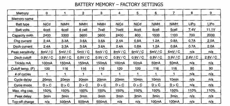
9 2. MOTOR BREAK-IN: To break-in brushed motors and adjust all related settings. 3. USER SETUP: To set various miscellaneous functions, such as fan control, temperature scale, audible tones, LCD contrast, etc. 4. DATA VIEW: To see specific data about the operating condition of Ice or the battery being conditioned, such as input and output voltages, battery temperature, battery resistance, charge or discharge time, and enter the charge and discharge voltage graphs. 5. CYCLE DATA: To view all charge or discharge capacity information for individual cycles, or all 10 cycles. 6. STEP CHARGE SETUP: To set Ice s four-step charge settings. SETTING A BATTERY INTO MEMORY SELECTING A MEMORY There are two main ways in which to configure Ice for conditioning of batteries. A memory bank is available for setting and storing pertinent information for up to 10 different batteries. After entering battery data into the memories, simply recalling the battery s appropriate memory number makes Ice instantly ready to go no need to re-configure settings when changing batteries! Once a battery s information is stored into a memory it will be saved until changed again manually. Ice s 10 memories are factory pre-programmed for different battery types, charge and discharge currents, etc. Refer to the Battery Memory Factory Settings chart on the fold-out section included with this manual for the default settings in each memory. Also on this sheet find a large printout of a blank memory chart. Use the blank chart to record your own personal memory settings. It is not required to use any of Ice s memories. In such case, the Main Memory screen #0 acts as the main setup screen for manually changing the battery, charge, discharge, or cycle settings. There is no other menu for manually setting parameters or starting a function. Read further to learn more about manually setting these parameters. To RESET all settings to the factory defaults, disconnect the input connectors from 12V DC power. Press and hold both the and buttons while reconnecting the input leads to 12V DC power. A brief initialization screen will appear, then the display will automatically change to the Main Memory screen. At this time, all previous settings will be CLEARED and reverted back to the factory defaults. Do NOT perform this reset if you do not wish to clear all settings in the memory! 9
10 SELECTING & NAMING BATTERY MEMORIES NAVIGATING THROUGH ALL OF ICE S SCREENS WILL START AT THE MAIN MEMORY SCREEN. If your battery parameters match any of those already listed in the included memory chart, simply select that memory number to quickly get Ice ready to handle your battery. Each memory screen shows a memory number and name. With the cursor pointing to the top line: 1. Memory Number: To change the memory number, press the dial once to highlight the memory number shown in brackets. Rotate the dial to find the appropriate memory number. 2. Memory Name: To change the memory name, press to automatically show the Memory Name Setup screen as shown at right. Rotate the dial to move the ^ symbol underneath the characters in the string of letters. Press dial to highlight letter, then rotate to change the letter. Press to move to the next letter and repeat this step as desired. Press dial to confirm all selections and highlight will disappear. When done press to return to Main Memory Screen. 3. When memory name and numbers are selected, press the dial to confirm selections and the highlight will disappear. If your battery type does not match any of the settings pre-programmed into a memory, or if you just do not wish to use the battery memories, simply adjust the settings in memory location #0, then start the charge, discharge and cycle functions while in this screen (see next page). ADJUSTING SETTINGS IN THE MAIN MEMORY SCREEN Within the Main Memory screen (as shown above), rotate the dial to move the cursor up or down. Press the dial to highlight the adjustable value. Rotate the dial to adjust the highlighted value. Re-press the dial to confirm the selection. Ice will automatically store parameters into memory one second after being entered. There is no need to manually confirm settings into memory separately. 10
11 1. Battery Info: Move the cursor next to the first line under the memory name. a. Press the dial to highlight the battery type. Rotate the dial to find the desired battery type that exactly matches your battery (NiCd, NiMH, Li- Ion or Li-Po). b. With the battery type still highlighted, press to highlight the number of cells (for NiCd/MH) or total voltage (for Li-Ion/Li-Po). Rotate the dial to find the number of cells or voltage which exactly matches the number of cells in your battery. For NiCd and NiMH, choose from 1-10 cells. For Li-Ion choose from 3.6, 7.2, 10.8 or 14.4V. For Li-Po, choose from 3.7, 7.4, 11.1 or 14.8V. WARNING!! NEVER set this voltage to a level that is higher than the battery s rated voltage. Li-Ion/Li-Po cells cannot handle overcharging in any way!! If a NiCd or NiMH battery does not achieve a true peak, the charge process will shut down automatically if the battery reaches 2.0V per cell. The maximum voltage for lithium-ion cells is 4.10V, and 4.20V for lithium-polymer cells. This feature is designed to protect the battery. For this reason, it is very important to set the proper voltage for your battery. c. With the #cells/voltage still highlighted, press to highlight pack capacity. Rotate the dial to find the battery capacity value which matches the rating of your battery. If the battery s exact rated capacity cannot be found, select the capacity which most closely matches the capacity of the battery. Choose from mAh. IMPORTANT!! For Li-Po and Li-Ion batteries, make sure the capacity setting matches the rating of the battery as closely as possible. Be very careful with batteries that are assembled in series or series/parallel configurations. Check with your battery s instructions or supplier if unsure of the pack s RATED capacity. d. Press the dial to confirm all of the above settings. 2. Charge Current: Rotate the dial to move the cursor down one line. To manually adjust charge current, press the dial, then rotate to find the new charge current which ranges from 0.1A (100mA) to 8.0 amps. For safety precautions, the maximum charge current value for Li-Ion and Li-Po batteries will be limited to their 1C value. Re-press dial to confirm setting. WARNING!! It is NOT RECOMMENDED to charge Li-Ion or Li-Po cells at a rate greater than their 1C value!! Supplying too much current to a Li-Ion or Li-Po battery can cause very serious damage (including fire!) to the batteries and the surrounding area! 3. Discharge Current: To manually adjust, press the dial, then rotate to find the new discharge current which ranges from 0.1A (100mA) to 10.0 amps. For safety precautions, the maximum discharge current value for Li-Ion and Li-Po 11
12 batteries will be limited to their 2C value. Do NOT discharge Li-Ion or Li-Po batteries at currents which exceed the discharge current rating of the battery as this can often cause a cell to overheat. Re-press dial to confirm setting. 4. Peak Sensitivity (NiCd and NiMH batteries only): This value determines the sensitivity/accuracy of the peak detection circuit. Adjustment of this value can help match the characteristics of your battery to the charger for better peak charges. For NiCd batteries the range is 5-25mV. For NiMH batteries the range is 3-15mV. A ZEROpk or Zero Volt Delta Peak setting is also available for NiMHs which means Ice will try to detect the exact voltage peak, but the battery s condition must be good and charge currents and voltages must be very clean and stable for ZEROpk to function properly. A lower number means the charger will try to be more precise in finding peak charge, but in certain situations could cause the charger to errantly stop peak charge too quickly, in which case it may be necessary to increase this number to 8mV or greater (especially if using an external AC power supply on the input). Press the dial, then rotate to find the desired peak sensitivity value. Re-press dial to confirm setting. 5. Discharge Cutoff Voltage: This is the voltage level that Ice will stop discharging the battery, and is shown as volts PER CELL in the pack (not total pack voltage). Press dial, then rotate to find the correct value. Re-press dial to confirm setting. a. Some NiCd and NiMH battery manufacturers rate the capacity (mah) of their batteries based on a discharge cutoff voltage of 0.9V per cell. So, to see if the battery is supplying the amount of capacity as rated by the manufacturer, set the discharge cutoff voltage to 0.8 or 0.9V. This is also a good voltage for stopping discharge of sub-c size cells to determine their useful run-time in minutes. However, for any A, AA or sub-c size cells that are used to power radio transmitters or receivers, set the discharge cutoff voltage to 1.1V per cell to get an idea of how long the battery will power the Tx and/or Rx. Most R/C receivers are not capable of maintaining control with a 4-cell NiCd/MH battery that is discharged below 1.1V per cell. The adjustable range for NiCd and NiMH batteries is V per cell. b. For Li-Ion/Li-Po batteries, the adjustable range is V per cell. A setting of V is recommended. 6. Trickle Charge Current (NiCd and NiMH batteries only): This is the amount of trickle charge current which will be applied to the battery only after fast charge has ended. To adjust, press the dial then rotate to find the new current. Re-press dial to confirm selection. The range is 0-500mA. If 12
13 charging A or AA size radio batteries (Rx or Tx), it is not recommended to set the trickle current to larger than 50mA. For sub-c batteries, the recommended trickle current setting is roughly C/20 (battery capacity rating divided by 20). If fast charge is stopped because the battery temperature reached the max. temperature setting (see below), trickle charge will not begin until battery temperature drops about 4 F (2 C) below the max. temperature setting. 7. Cutoff Temperature: Ice can monitor the temperature of the battery which is connected to the banana jack outputs. This feature is used in conjunction with Ice s optional Temperature Sensor (DTXP4171) which can be found at local retailers. The Hobbico Accu-Cycle Elite Temperature Sensor (HCAP0281) and the Triton Thermal Probe from Great Planes (GPMM3151) are also directly compatible. Monitoring a battery s temperature in addition to its voltage can result in the most accurate full charges without damaging the battery, and is highly recommended for use with Li-Ion/Li-Po batteries. The adjustable range is from F (10-55 C). The sensor jack is located on the right side of the charger underneath the banana jacks. When properly connected to the jack, the sensor s white wire will be on the left and the black wire will be on the right. a. If it s NOT desired to measure the temperature of a battery, make sure the temperature sensor is NOT connected to the charger. b. To change the temperature scale from Celsius to Fahrenheit or viseversa, see the User Setup Menu on page 25. c. To adjust the temperature setting, press the dial then rotate to find the new temperature. Re-press dial to confirm setting. d. The recommended maximum temperature for NiCd batteries is F (45-55 C). The recommended maximum temperature for NiMH batteries is F (43-52 C). NiCd and NiMH cells which are AAA size or smaller should use lower values. Start with lower temperatures first and if necessary adjust the temperature setting upward as needed in small increments and closely monitor the charge progress. e. The maximum temperature for Li-Ion/Li-Po batteries varies by cell manufacturer, but as a general recommendation the maximum temperature should not exceed F (32-35 C). For Li-Ion/Li-Po batteries, it is better to be safe than sorry! Start with lower temperatures first and if necessary adjust the temperature setting upward as needed in small increments and closely monitor the charge progress. Note: It s a good idea to set the temperature cutoff approx. 5 F lower than suggested because battery temperature will continue to increase for a short time after charge or discharge has ended. 13
14 f. During charge, if the battery reaches the selected temperature setting the charge process will completely stop and will not re-start. Setting the temperature value too low may cause Ice to stop charging the battery before it reaches full charge. In this case, increase the temperature setting by a small amount, making sure not to allow the battery to overheat. Setting the temperature value too high may cause the battery to overheat before full charge has been reached. In this case, decrease the temperature setting. g. During discharge, if the battery reaches the temperature that is set in this screen the discharge process will temporarily pause to allow the battery to cool down to a safe temperature. The discharge process will automatically resume when the battery s temperature drops about 4 F (2 C) below the maximum temperature setting. 8. Number of Cycles (NiCd and NiMH batteries only): This is the number of times Ice will consecutively perform a charge-to-discharge or discharge-tocharge cycle (see 10. Cycle Mode below for how to set which function to perform first). The range is from 1-10 cycles. Press the dial, then rotate to set the number of times to perform a cycle. Re-press dial to confirm setting. 9. Cycle Delay (NiCd and NiMH batteries only): This sets a time delay to occur between charge and discharge while cycling in order to allow the battery to cool. The range is from 1-30 minutes. Press, then rotate the dial to find the amount of time for the delay. Re-press dial to confirm setting. 10. Cycle Mode (NiCd and NiMH batteries only): This sets the pattern in which cycles are performed. There are two options: charge followed by discharge (C>D), or discharge followed by charge (D>C). 11. Maximum Charge Capacity: This sets the maximum amount of capacity that the charger will deliver to the battery during charge. This feature can be used for two different purposes: a. If full charge has not been detected on the battery for some reason, fast charge will stop completely when this max. capacity value has been reached. This is a safety feature designed to protect the battery pack and user from an overcharge condition. b. Cell manufacturers recommend to apply a partial charge to batteries before being put away for long-term storage (over the winter, for example). In this application, it is recommended to set this maximum charge capacity to 30% for NiCd/MH batteries, and 10% for Li-Ion/Li- Po batteries. 14
15 Press, then rotate the dial to find the desired max. capacity. For NiCd and NiMH batteries the adjustable range is %. This means, if peak voltage is not detected first Ice will automatically stop fast charge at the value equal to the battery capacity setting in point #1c on page 11 ( Pack Capacity ) multiplied by the percent entered in this maximum charge capacity setting. So, if the battery capacity entered was 2400 and if the maximum charge capacity percentage entered here is 150%, the charger will automatically stop fast charge when (2400 x 150%) 3600mAh of energy is delivered to the battery. For Li-Ion and Li-Po batteries, the adjustable range is %. It is recommended not to allow these battery types to charge more than 105% to 110% of their rated capacity. For safety precautions, it s recommended to keep this value close to 100%. 12. Peak Delay (NiCd and NiMH batteries only): Sometimes during the early stages of peak charge a battery s voltage can be unstable and cause the peak detector to accidentally stop peak charge. This peak delay feature temporarily de-activates the peak detection circuit at the beginning of charge to prevent the charger from accidentally shutting down too early. Usually, a battery s voltage becomes stable in a very short period of time, whereby the peak detection circuit can be re-activated. The adjustable range is 1-10 minutes. 13. Top-off Charge (NiMH batteries only): Nickel-metal hydride batteries can benefit from having a short top-off charge applied to the battery after peak charge has ended. This top-off charge current is typically larger than a trickle current and is designed to help fill the pack to maximum capacity more quickly. If set, top-off charge will automatically begin 5 minutes after fast charge has ended in normal and reflex charge modes only (not automatic, impulse or four-step mode). It s recommended that the top-off charge current setting be no greater than 1/5 th of the pack capacity value that was entered in #1c on page 11. If the battery capacity value entered was 3000mA, the top-off charge current should be no greater than (3000mAh / 5) 600mA. The adjustable range is off-1000ma (1.0A). Top-off charge will be applied for 20 minutes. If the battery s voltage peaks or its temperature reaches the maximum setting before the timer expires, top-off charge will end automatically. 15
. Press and hold dial to enter the charge/discharge/cycle screen.")
16 SELECTING & STARTING CHARGE, DISCHARGE OR CYCLE To start a charge, discharge or cycle function or to change the charge or discharge mode: 1. While in the Main Memory screen, press and HOLD the dial for 2 seconds. The Charge / Discharge / Cycle screen will show (see right). Press and hold dial to enter the charge/discharge/cycle screen. Press dial to highlight charge mode inside arrows. Rotate dial to select the desired charge mode: NORMAL, REFLEX, RE-PEAK or AUTOMATIC. 2. Charge Mode: Rotate the dial to place the cursor next to CHARGE. Press the dial to highlight the charge mode, then rotate the dial to select the desired charge mode. Select one of the four charge modes, as designated within the arrows next to CHARGE. Re-press the dial to confirm the selection. a. Normal Charge Mode (NiCd and NiMH batteries only): Linear current is delivered to the battery in normal mode. While NORMAL is highlighted, a note about reserve time will show at the bottom of the screen. See the Reserve Time Function section on page 17 for full details about the reserve time function. If it is not desired to use the reserve time function, leave it set to off. To START CHARGE, place the arrow cursor next to charge and press and hold the dial for 2 seconds. b. Reflex Charge Mode (NiCd and NiMH batteries only): As shown in the chart at right, in reflex charge (sometimes referred to as burp or reverse pulse charge ) normal current is delivered to the battery for 99.6% of every second, but for the remaining 4 milli-seconds a very deep discharge current is delivered to the battery. The quick discharge current is equal to the charge current setting multiplied by 4. Reflex charge is believed by some to help remove oxidizing gas bubbles from the battery s cell plates, allowing the battery to charge more efficiently, and is thought to be especially helpful on older NiCd batteries. Reflex charge mode may not be recommended by some NiMH battery manufacturers (check with 16
17 your supplier). While REFLEX is highlighted a note will be shown at the bottom of the screen for reserve time. See the Reserve Time Function section below for how to use the reserve time function if desired, otherwise leave it set to off. To START CHARGE, place the arrow cursor next to charge and press and hold the dial for 2 seconds. Reserve Time Function When NORMAL or REFLEX charge mode is selected, reserv (00): off will show at the bottom of the screen. This reserve time feature can be thought of like a charge scheduler, by setting a timer which will cause Ice to finish putting a full charge on the battery immediately before the start of a race so the pack is at optimum race-readiness. Referring to the diagram at right, the number inside the parenthesis is the expect time the number of minutes that Ice calculates to be needed to fully charge the battery (based on charge current and battery capacity values entered). The number on the right is the reserve time the number of minutes from now that you want the battery charge process to be finished. For example: Say the next race starts 90 minutes from now, and that Ice calculated an expect time of 50 When REFLEX or NORMAL are highlighted, press to highlight the minutes reserve time at the bottom. Rotate dial to select a reserve time. Press to needed to confirm setting. Press and hold dial to start reserve time charge process. fully charge the battery. Setting the reserve time to 80min means Ice will wait 30 minutes (80 min. reserve time 50 min. expect time) and THEN start the charge process. In the end, if the total time needed to charge the battery was indeed 50 minutes, this will leave 10 minutes (90 min. until race time 80 min. reserve time) for the battery to cool and to get to the start line for the race. It may take some practice and careful attention to get the reserve time function to work as desired. To maximize the effectiveness of the reserve time function, the capacity setting in the main menu may need to be set to the most realistic possible maximum capacity 17
18 for your battery as opposed to the pack s actual rated capacity. For example, if your 3300mAh battery pack can regularly accept a charge of up to, say, 3562mAh, you should set the capacity value in Ice s Main Memory Screen to 3600mAh. Reserve Time Function (continued) When started, the reserve time delay screen above will show, and the START timer will begin counting down. When the reserve time delay expires, the charge process will start automatically. The minimum reserve time will be no less than the calculated expect time. Max. reserve time is 600 minutes. c. Re-peak Charge Mode (NiCd and NiMH batteries only): In re-peak charge mode, Ice can peak charge the battery once, twice or three times in a row automatically. This is good for making certain the battery is fully charged, and for checking how well the battery receives fast charges. And, Ice will track how much capacity was added during each re-peak. A good battery will have low charge capacity values for the 2 nd and 3 rd re-peak charges. Batteries having higher capacity values for the 2 nd and 3 rd re-peak charges are not likely receiving peak charge as well. A five minute cool-off delay occurs after each re-peak charge. See the diagram below for using re-peak charge mode. To START CHARGE, place the arrow cursor next to charge and press and hold the dial for 3 seconds. When RE-PEAK charge mode is highlighted, repeak cycle: 1 will show at the bottom. Press to select the repeak cycle number. RE-PEAK CHARGE Rotate the dial to find the desired number of times to re-peak charge the battery. Press to confirm selection. Press and hold dial to start the re-peak charge process. 18
19 RE-PEAK CHARGE (continued) In the re-peak charge status screen, 1 is the repeak charge being performed at this time, and 3 is the total number of re-peaks that will be performed. This screen will change to END: DELTA-PEAK when finished. Shows the charge capacity that was delivered to the battery BEFORE ANY re-peak charges were applied. Shows the total amount of ADDITIONAL charge capacity that was delivered to the battery during all re-peak charges combined. When ALL re-peak charges are done, the charge capacity data for all re-peaks can be seen in the Cycle Data View screen as shown below (see flowchart to find the cycle date screen). If a battery was charged or discharged PRIOR to starting re-peak charge, those capacity values will be shown for cycle #1. Charge capacity added during re-peak #1 will be shown under cycle #2. Charge capacity added during re-peaks #1, and #2 will be shown under cycle #3. Charge capacity added during re-peaks #1, #2 and #3 will be shown under cycle #4. d. Automatic Charge Mode (NiCd and NiMH batteries only): Ice can detect the condition of the battery which is connected to the output and automatically charge the battery. IMPORTANT!! Make sure the proper battery type and temperature settings are entered before starting auto charge! Ice will likely charge batteries better if the normal charge mode is used (assuming all user settings are properly tailored to the battery), but the Automatic mode can be used. Peak sensitivities are pre-set at 5mV for NiCd, and 4mV for NiMH. Fast charge will end if maximum battery temperature is reached (if set) or if peak charge is achieved. To START CHARGE, place the arrow cursor next to charge and press and hold the dial for 3 seconds. 19
20 e. For Li-Ion and Li-Po batteries, the cc/cv or constant current/ constant voltage is the only charge mode available. If the battery s temperature reaches the maximum setting (if set) before full charge is detected the charge process will end automatically. To START CHARGE, place the arrow cursor next to charge, and press and hold the dial for 3 seconds. Note: The cc/cv charge method is COMPLETELY DIFFERENT than the peak detection method that is used to charge NiCd or NiMH batteries. In the beginning, Ice forces constant current into the battery at the rate which is set in the Main Memory screen. When Li- Po batteries reach 4.20V per cell, or Li-Ion s reach 4.10V per cell, Ice automatically stops delivering constant current and starts applying constant voltage to the battery. Here, the charger is no longer forcing current to the battery. Instead, the battery is only draining the amount of current from the charger that it can take naturally. As Li-Ion/Li-Po batteries become more fully charged they will take less and less current from the charger. Here, the actual current coming from the charger will gradually drop below the value that was set in the Main Menu. THIS IS NORMAL!! When charge current drops to approx. 100mA, Ice will beep to indicate that regular quick charge has finished. At this time, Ice will automatically start a unique LiPo trickle charge current (based on application of a constant-voltage) as indicated by Trk which will flash on the current line on the screen shown above right. When this lithium trickle current drops to 30mA Ice will completely stop all charge current and Trk will change to 0.00A. 3. Discharge Mode: While in the Main Memory Screen, press and hold the dial for 2 seconds. The designated discharge mode (automatic or normal) will be shown within the arrows next to D- CHARGE. To change the discharge mode, move the arrow cursor next to D- CHARGE. Press the dial to highlight the text inside the arrows, then rotate the dial to select the discharge mode. Re-press 20
21 dial to confirm selection. TO START DISCHARGE, press and hold the dial for 2 seconds. If a temperature sensor is used, discharge will temporarily pause if maximum battery temperature is reached, and will automatically resume when the battery temperature drops approx. 4 F (2 C) below the maximum setting. a. Normal Mode (all battery types): Discharge is guided by all user settings in the Main Memory screen. Discharge current is linear, and cutoff voltages are those which are set in the main memory screen. b. Automatic Mode (NiCd and NiMH batteries only): Most user settings are ignored. Ice automatically sets the current based on the condition of the battery. Discharge cutoff voltage is pre-set in this mode to 0.8V per cell. Ice will likely discharge batteries better if the normal discharge mode is used (assuming all user settings are properly tailored to the battery), but the automatic mode can be used. 4. Cycle Mode (NiCd and NiMH batteries only): While in the Main Memory Screen, press and hold the dial for 2 seconds. Place the cursor in front of CYCLE, then press and hold the dial TO START CYCLING (see Main Memory screen and page 14 for setting # of cycles, cycle delay, etc.). Note: The normal charge mode and normal discharge mode is used during cycles. 5. To manually abort any function, press the button at any time to return to the Main Memory screen. CHARGE & DISCHARGE STATUS SCREENS & GRAPHS While a function is being performed a Status Screen will automatically show on-screen (see next page). All information will be updated automatically every second while the function is being performed. Information shown in the Status Screen is as follows: 21
22 number of times discharge or charge have been performed elapsed time, counted in seconds capacity delivered to battery during charge, or from battery during discharge voltage measured at the output banana jacks current being delivered to/from battery shows the temperature of battery when sensor is used additional capacity provided during top-off charge or re-peak charge the maximum temp. battery reached during a function the maximum voltage reached by battery during charge the average voltage of battery during discharge voltage measured at Ice s input connection the internal resistance of battery measured during discharge, in milli-ohms select the voltage range setting that Ice will use in voltage graphs, select auto or manual Note that the voltage reading in the Status Screen above will show the voltage of the battery while it s under a load. Loading will skew the voltage reading, which is normal. A higher load will skew the reading more than a smaller load. Ice s custom display can show graphical images of the battery s voltage curve while charge or discharge is in progress. Various types of data can be viewed and adjusted in the voltage curve graphs. 1. While in the Status Screen shown above, move the cursor to the volt rng or voltage range line at the bottom. Press the dial, then rotate to select either auto mode, where most graph settings will be selected automatically by Ice, or select manual mode in which you can manually adjust more parameters shown on the graph. Re-press the dial to confirm the selection. 2. Press anytime while the Status Screen is shown to see the graph. The graph will show as long as the charge or discharge function has been operating for at least 5 seconds. Press again to return to the Status Screen shown above. Pressing at any time will STOP the function completely. 3. Manual View: Set the volt rng line in the Status Screen to manual view, then press to see the graph. The first adjustable parameter will automatically be highlighted (graph zoom). Refer to the diagram below for this and the other adjustments: 22
.")
 4.727V, and the lowest point is (4.367-0.36) 4.007V. After adjusting the voltage range R:, press the dial to again highlight the zoom factor.")
23 The zoom factor in the lower-right will be highlighted first. Rotate dial to select zoom factor. x1 is the closest view. x5 is the widest view. Press dial to highlight Vc which is the voltage at the center point of the y-axis (vertical). Rotate dial to change the voltage at the center point of the graph Press dial to highlight R then rotate to set the voltage range of the y-axis. As shown above, with R: being 0.36V, the highest point on the y-axis is ( ) 4.727V, and the lowest point is ( ) 4.007V. After adjusting the voltage range R:, press the dial to again highlight the zoom factor. Press anytime while in a graph screen to return to the Status Screen. 4. Auto View: When the auto mode is selected on the volt rng line of the Status Screen, Ice will automatically set nearly every graph parameter. Select auto, then press to view the graph. Note that auto will flash next to the R: mark along the bottom of the screen. The only adjustable parameter is the zoom factor in the lower-right corner, which will already be highlighted. Rotate the dial to adjust the zoom factor. The voltage curve can be zoomed-in for detailed viewing ( x1 ), or a wider view of the curve can be seen when zoomed-out ( x5 ). At x1, the screen width equals 2 minutes of time and data is updated every second. At x5, the width of the screen equals 10 minutes of time and data will be updated every 5 seconds. Note that when adjusting the zoom value here the Vc and R: values will automatically change as well. On-screen, the graphs always advance from right to left. Along the top of the auto or manual graph screens the elapsed time will be shown in seconds (topleft), the charge/discharge current level will be shown in amps (top-center), and the voltage at Ice s output at that instant will be shown (top-right). When a function ends while a graph is being shown, the audible tones will sound (if set) and the graph will stop moving the voltage curve to the left. Press to 23
24 return to the Status Screen. The Status Screen will be flashing a message indicating the final result of the operation which was just completed, such as END: DELTA-PEAK when peak charge has ended, END: CUT-VOLTAGE when a discharge has ended, etc. One unique message is FLAT-LIMITED if during peak charge the NiCd or NiMH battery s voltage stops rising, but it also does not fall (as most NiCd or NiMH batteries will do), this message shows to indicate that the battery s peak voltage is flat and unchanging and Ice will automatically stop charging the battery as a safety precaution. Press to stop the function and leave the Status Screen. Then, go to the Data View screen to see the finalized data (see the flowchart and Data View section). MOTOR BREAK-IN MENU While in the Main Memory screen, press to find the Motor Break-In screen (see below). The Motor Break-In feature is designed to break-in new brushes on brushed electric motors by delivering up to 10 amps of current at a selected voltage for a selected time. Ice will try to maintain 10A on the output, but only if the motor will allow it. It is important that the power source for Ice can maintain 12 volts and 15 amps to fully utilize this feature. Power to the motors is pulsed and not linear. 1. Rotate the dial to move the cursor up or down to the feature you wish to adjust. 2. Set Voltage: With the cursor pointing to set volt, press the dial once to highlight the voltage value. Rotate the dial to set the appropriate voltage of volts. Re-press the dial to confirm the voltage setting. Set the voltage to match the nominal operating voltage specification of your motor as closely as possible. Do not set the voltage too high, as permanent damage to the motor could result. Note: Motors with high internal impedance may have difficulty working properly with the motor break-in function. It may be necessary to set the voltage slightly higher here in order to turn such motors. 3. Set Time: Rotate the dial so the cursor points to set time. Press the dial once to highlight the 0m value. Rotate the dial to adjust number of minutes in the operational time, ranging from minutes. Press to move the cursor to the 10s value. Rotate the dial to adjust the number of seconds in the operational time. Press the dial to confirm the total break-in time setting. 24
25 4. Make sure the motor is firmly mounted to a motor stand prior to operation, and that the motor s output shaft is NOT connected to or touching anything prior to starting this function! 5. Connect the motor s white positive lead to Ice s red, positive (+) banana jack, and connect the motor s blue negative lead to Ice s black, negative (-) banana jack. 6. To start the motor break-in function, make sure no values on-screen are highlighted, then press and hold the dial. The RUNNING screen will show during operation, followed by the END screen when the motor break-in function has ended. The operating conditions of the break-in function will show along the bottom of the screen. USER SET-UP MENU While in the Main Memory screen, press twice to find the User Setup screen. Numerous miscellaneous functions can be configured in the User Setup screen. Rotate the dial to move the cursor up or down to the feature you wish to adjust (see next page). Press the dial to highlight the adjustable value. Rotate the dial to adjust the value, then re-press the dial to confirm the selection. 1. Fan Control: Ice s built-in fan has two modes, auto and on. In the auto mode, the fan will automatically turn on when the internal temperature of the charger reaches 122 F (50 C). This is designed to protect the charger s circuitry from damage caused by overheating. In the on mode, the fan will run continually until turned off manually. 2. Temperature Mode: The temperature scale can be changed between Fahrenheit ( F) and Celsius ( C). 3. Button Sound: Ice can be configured so that anytime a button is pressed or the dial is rotated one click an audible tone will beep. This can help to confirm that functions are being adjusted. These beeps can also be turned off (but will still sound if errors occur). 25
26 4. Finish Sound: A sound will be emitted to indicate that a function has been completed. This feature adjusts the length of time that the sound will play, ranging from 5 seconds to 3 minutes, or this feature can be turned off. 5. Melody: Select from any one of 5 different tunes to be played to indicate that a feature has ended. This feature can also be turned off. 6. LCD Contrast: Adjust the contrast of the LCD screen for best viewing. Adjustable range is from lightest (1) to darkest (12). 7. User Name: At the bottom of the screen, enter anything you wish to identify your charger. This name will appear on the opening screen when power is initially applied to Ice. Press the dial to enter the User Name Set-up screen to find the User Name Set-up Screen (see above). Rotate the dial to move the ^ symbol underneath the characters in the string of letters. Press dial to highlight letter, then rotate to change letter. Press to move to the next letter and repeat this step as desired. Press dial to confirm all selections and highlight will disappear. Repeat this step for all other characters as desired. Press to return to the User Setup screen. When finished adjusting the User Setup screen, press twice to return to the Main Memory screen. DATA VIEW While in the Main Memory screen, press three times to find the Data View screen. This screen shows various types of data pertaining to the input or output of the charger. This screen can be seen only before a function has started, or after a function has ended (not while a function is being performed). 1. Input Voltage: Shows the DC voltage at Ice s input lead. DATA VIEW 2. Output Voltage: Shows the DC voltage at Ice s banana jacks. It is important to understand that the condition of the connector lead on the battery and the charger s output can affect the accuracy of the voltage reading. 26

27 3. Battery Temperature: Shows the temperature of the battery as measured with the optional temperature sensor. If no sensor is connected the display will show No. Sens. 4. Peak Temperature: In conjunction with the Battery Temperature feature above, Ice will constantly record the highest measured temperature of the battery which is connected to the output. 5. Battery Resistance: Ice will measure the battery s internal resistance starting 2 minutes AFTER discharge has stopped, and is shown in milliohms ( ). Battery resistance will not be measured if cell voltage is lower than 1.0V for NiCd/MH batteries or 3.0V for Li-Ion/Li-Po batteries. This is because the most important time to judge a battery s internal resistance is when it is closer to full charge. A lower resistance value is better, indicating the charger can likely condition the battery more efficiently and accurately. Important: This value can be greatly affected by the quality of the connection between the battery and Ice s output. A solid physical connection is important to having a good electrical connection. High quality components in the battery s own lead and the adapter lead between the battery and charger is also very important. Silicon insulated wire has lower resistance, as do gold plated terminals and copper conductors. Larger gauge wire (with a smaller numerical value) also provides lower resistance. A battery whose internal resistance gradually worsens over time will be showing signs of aging, and could also result in poor charge and/or discharge capacities and may need replacement soon. 6. Charge Time: Records the amount of time needed to complete a charge function, not counting the time a battery is in trickle charge (NiCd and NiMH) or top-off charge (NiMH only). Shown in seconds. 7. Discharge Time: Records the amount of time needed to complete a discharge function. Shown in seconds. 8. Graphic Data View: Ice s graphic display can also show voltage curve waveforms after a charge or discharge function has ended (not for cycles). To view the final voltage curve, scroll the arrow cursor down to the graphic data view line, then press the dial to view the graph. a. A straight vertical line will appear in the middle of this graph (see diagram at right). This is the graph cursor. Rotating the dial will cause the 27

28 graph cursor to move sideways.to find the voltage at any point on the curve, move the cursor to that point on the curve. The voltage where the graph cursor line intersects the curve will be shown in the upper-right corner of the screen. b. Press to select the other adjustable graph parameters, as shown in the diagrams below: c. Press the dial anytime to go back to the Data View screen. The total length of time that battery voltages will be graphed in this screen will be from the start to finish of either charge or discharge. For NiCd/MH batteries, the overall graph should be shown in a single display. For lithium batteries, the overall graph period is designed for a maximum of 3 hours based on a 1C rate (data past 3 hours won t be displayed). When using the automatic charge or discharge mode, the overall graph period will be 2 hours maximum. 28
29 Information is NOT shown in graph form for re-peak charge mode, time delays, top-off charge, cycles, or discharge-before-charge steps. CYCLE DISPLAYS While in the Main Memory screen, press three times to find the Cycle Data screen. This screen shows the battery s capacity and voltage readings for each charge and discharge period for up to 10 full cycles. The cycle number is shown on the left side of the screen. Rotating the dial will scroll the cursor up and down the screen (continue scrolling down to view data for cycles 4 through 10). Charge data is marked by C:, with the charge capacity shown in mah and the peak battery voltage is shown on the right. Discharge data is marked by D:, with the discharge capacity shown in mah and the average battery voltage is shown at right. Cycling NiCds once monthly can help maximum the overall performance of the cells. NiMH batteries benefit much less from cycling. Cycling can help to determine a battery s ability to store its maximum rated capacity. If a battery can only store a small fraction of its rated capacity it s likely reaching the end of its useful life and may need to be replaced. New batteries, or older batteries which have not been used or cycled frequently may need to be broken-in before they will perform to their rated capacity. Comparing how much charge energy, or mah, that was delivered to the battery vs. the subsequent discharge capacity in mah can help to determine how well the battery held the previous charge. Also, comparing a battery s measured discharge capacity to its rated capacity is an indication of the battery s general condition. If a fully charged battery provides less than 70% of its rated capacity it may no longer be safe to use. Additional cycles can be attempted to try and increase the battery s storage capacity to near 100%, but if repeated attempts fail to improve performance the batteries should be replaced. 29

30 FOUR-STEP CHARGE SETUP CAUTION! The Four-Step Charge method is recommended for use by experienced users only!! If set improperly, the Four-Step Charge method can cause severe, permanent damage to the battery! If you are unsure about how to use this function, do not use it. The Four-Step Charge method is designed for very high charge efficiency for NiMH batteries. This feature can be used on NiCd batteries also, but only if the peak sensitivity value is set properly (see page 32). NEVER USE THE FOUR- STEP CHARGE MODE WITH LI-ION OR LI-PO BATTERIES AS SEVERE, PERMANENT DAMAGE TO THE BATTERY AND ITS SURROUNDINGS WILL RESULT!! Parameters which are set in the Four-Step Charge screen do NOT affect those which are set in the Main Memory screen. The Four-Step and Main Memory screens are completely independent of each other. And, a temperature sensor is REQUIRED when using the Four-Step Charge mode. Ice will not allow Four- Step Charge to start unless a temperature sensor is connected. The Four-Step Charge method divides the overall time needed to charge a battery into four separate periods or steps (see diagram above). The maximum charge capacity and charge current is set separately for each of the four steps. The purpose of the Four-Step Charge mode is to deliver as much energy to the battery as possible for racing punch without damaging the battery, but also to allow for the most accurate peak detection as possible for maximum run-time. In the beginning, for charge step 1, it s important that the battery s voltage becomes stable, so the charge current setting should be rather conservative. Then, when the battery voltage is stable, much higher current can be delivered in step 2. The higher currents in step 2 will cause the battery to generate heat after a period of time, so it is best to reduce current in step 3. Finally, for step 4, it s best to reduce current again so the battery s voltage is more stable which will allow the peak detection circuit to work more accurately to pack as much run-time capacity in the battery as possible. It is important to note that in Four-Step Charge mode the peak detection circuit functions ONLY in step 4 (not steps 1-3). The maximum amount of charge capacity delivered to the battery during each step effectively determines how long the charge current will be delivered to the 30
31 battery during the step. Be careful not to set the capacity value too high especially in steps 2 and 3 where the current settings are higher. The higher the capacity setting, the longer that current will be applied to the battery during the step, and the more likely the temperature sensor will trip due to heating and stop the charge process prematurely. It may take some practice and careful attention to dial-in the Four-Step charge mode for your battery. See the chart that follows for a breakdown of the settings for each step. For example, see the following chart for how to set the Four-Step charge process for a 3300mAh battery and 3600mAh NiMH battery. 1. While in the Four-Step charge set-up screen (see next page), rotate the dial so the cursor is next to the line underneath the Step Charge Setup heading: 31
. Set this value slightly higher for NiCd batteries. c. Press to highlight the maximum temperature setting.")
32 a. Press the dial to highlight the number of cells. Rotate dial to adjust # cells to match the battery, ranging from 1 to 10 cells. b. Press to highlight the peak sensitivity value. Rotate dial to adjust as desired ranging from 3-15mV/cell (or ZEROpk for NiMH batteries). Set this value slightly higher for NiCd batteries. c. Press to highlight the maximum temperature setting. Rotate the dial to adjust as desired, ranging from F (10-55 C). d. Press dial to confirm settings. 2. Rotate the dial to move the cursor down to the capacity line (just under the graph). This line shows four different capacity values, each being the maximum capacity that will be delivered to the battery during each of the four steps. The range for each step is mAh. a. Press the dial to highlight the capacity value on the left which is for step #1. Rotate dial to adjust this capacity value. b. Press to highlight the next capacity value to the right which is for step #2. Rotate dial to adjust this capacity value. Repeat this step 2 more times to adjust the capacity for steps 3 and 4. c. Press dial to confirm all capacity settings. 3. Rotate the dial to move the cursor down one line to the charge current line. This line shows four different charge current values that will be delivered to the battery during each of the four steps. The range for each of the four steps is 0.1 to 8.0 amps. a. Press the dial to highlight the charge current value on the left which is for step #1. Rotate dial to adjust this current value. b. Press to select the next current value to the right, which is for step #2. Rotate dial to adjust this current value. Repeat this step 2 more times to adjust the current for steps 3 and 4. c. Press dial to confirm all charge current settings. 4. Rotate the dial to move cursor down as there are 7 additional lines of features in this menu. 32

33 5. Expect Time: When the battery capacity and charge current values are entered into the Four-Step Charge menu, Ice will calculate how much time is expected to be needed to fully charge the battery while in four-step Charge mode. This time will be shown on the expect time line. Note: This time does not include the temporary pauses that Ice needs to check battery temperatures (if applicable) and so on. 6. Reserve Time: Setting the reserve time function for the Four-Step Charge mode is done in the main Four-Step Charge screen as shown at right. Here, the reserve time feature operates the same way as in the CHARGE / DISCHARGE / CYCLE screens Set the reserve time to be the number of minutes before the next race starts plus enough time to let the battery cool beforehand. The minimum reserve time setting cannot be lower than the calculated expect time above, and maximum is 600 minutes. The reserve time does NOT include the time needed for discharge-before-charge (see below). It is important to remember that the reserve time will vary depending on the charge current selection, capacity rating of battery, etc 7. Trickle Charge: Rotate the dial to place the cursor in front of this line. This sets the trickle charge current that will be applied to the battery after fast charge ends. Press dial to highlight the value, and rotate to select the value which ranges from 0-500mA. 8. Discharge > Charge: Rotate the dial to place the cursor in front of this line. This discharge-before-charge simply instructs Ice to automatically discharge the battery before starting the charge process. Press dial, then rotate to either turn this feature on or off. The discharge current here is automatically set to the maximum battery capacity entered in 2b (on page 32) multiplied by 4. For simplicity, it is best to set this to on to empty the battery before starting the Four-Step Charge mode. 9. Impulse Charge: Refer to diagram at right. This feature functions in Four-Step mode only, and charges the battery at a current equal to the charge current setting x 1.5 for 0.5 seconds, every 3 seconds. The charge current at all other 33
34 times is as set in the Four-Step Charge screen on page 32. The impulse charge method is much the opposite of the reflex charge method. Instead of applying high level negative charge pulses to the battery for short intervals, Ice applies high level positive charge pulses at regular intervals. And as with reflex mode, the impulse method is thought by some to help clear a cell s internal plates from build-up of oxidizing gas bubbles, allowing the batteries to perform better. Decide which steps to have the impulse mode function, which can be any combination of steps 1, 2 or 3. Impulse charge does NOT function in step 4. See the diagram below for how to set this function. Press anytime to remove the adjustment cursor arrow. 10. Reflex Charge: As with the impulse charge mode, reflex charge can be used in the Four-Step charge mode. Decide which steps to have the reflex charge mode function, which can be any combination of steps 1, 2 or 3. Reflex charge does NOT function during step 4. See the above diagram for how to set this feature. Note that impulse charge and reflex charge can be applied to the battery at the same time! 11. Temperature Check: The Four-Step Charge mode REQUIRES use of a temperature sensor! Ice will not allow the Four-Step charge mode to function without the sensor. This temperature sensing feature can be set to function in any combination of steps 1, 2 or 3 and is set the same way that 34
35 impulse and reflex functions are set (see diagram on the previous page). In steps 1-3, if the battery s temperature reaches the temperature setting at the top of the Four-Step Charge screen Ice will pause the charge function until the battery s temperature drops approx. 4 F (2 C) below the temperature setting, then charge will re-start automatically. The temperature sensing feature ALWAYS functions during the 4th step, and if the battery s temperature reaches the temperature setting during the 4th step Ice will automatically stop charging completely. TO START THE FOUR-STEP CHARGE mode, when the Four-Step Charge screen is shown press the dial and hold it for 2 seconds. The Status Screen will then appear and show which charge step is being performed. For example, if impulse and reflex modes are set as shown at right (impulse for steps 1 and 3, reflex for steps 2 and 3) the Status Screen will show as below: 35
36 When Four-Step Charge ends, go to the Data View screen to see the final charge data. ERROR MESSAGES & TROUBLESHOOTING GUIDE IntelliPeak Ice s solid-state circuitry offers protection against damage which could be caused by short-circuit or reverse polarity conditions, and more. Here is a list of possible error messages which might show on-screen, and an explanation of the problem: Input voltage The present input voltage is xx.xxv. Please check the input voltage. The input voltage must be 11V~15V. No battery A battery is not connected to the output. Please connect the battery to the output then restart! Reverse polarity A battery is connected to the output in reverse! Please correctly connect the battery to the output. Open circuit A battery is disconnected during an operation. Please reconnect the battery and restart! Short-circuit Output short-circuited. Please check the output. Note: When short circuit occurs on the output Ice will continue to try and charge for 2 minutes at the selected current. This is by design, as sometimes cells which have previously been completely discharged (after a race, with a cell discharger, even with Ice which can discharge to 0.1V) will have such low voltage that it might APPEAR that the output is short circuited when really it is not. If a fully discharged cell is connected, its voltage will quickly rise when charge is applied and the charger will continue to charge as normal. However, if the output is truly short circuited the voltage on the output will never increase and after 2 minutes Ice will stop charge and display this message. Low output voltage Output voltage is lower than the selected cells or voltages. Please select proper cells or voltages. Either Ice s voltage setting is incorrect, or the battery s rated voltage exceeds the setting. 36
37 High output voltage Output voltage is higher than the selected cells or voltages. Please select proper cells or voltages. Either Ice s voltage setting is incorrect, or the battery is in poor condition. No motor A motor is not connected to the output. Please connect the motor to the output. Motor disconnection A motor has become disconnected during an operation. Please reconnect the motor and restart! Sensor Connection A temp sensor must be used in 4 step mode. Connect DTXP4171 temp sensor. Temperature sensor A temperature sensor is connected in reverse or is defective. Bat. Temp too low Battery temp is too low to be operated! This message will show if the battery temperature is (a) lower than 32 F (0 C) during an operation, or (b) lower than 14 F (-10 C) when in idle mode. If this shows, allow battery to warm before proceeding. Bat. Temp too high Battery temp is too high to be operated! If this shows, allow battery to cool before proceeding. This message will clear when is pressed. Charger too hot! Please wait until the charger cools! This message will show when Ice s own internal temperature exceeds 239 F (115 C). Here, operations will pause temporarily, then resume automatically when internal temp. returns to below 158 F (70 C). This protects Ice s electronics from damage due to excess heat. Internal Sensor - Internal temp is too hot! If Ice s internal temperature exceeds 239 F (115 C) the display will first show Charger too hot and all operations will temporarily pause. If the internal temperature continues to increase over 257 F (125 C) the Internal sensor error message will show. If this happens a problem must exist with the charger contact Hobby Services for details. Data Communication Something is wrong with the internal circuit. Contact Hobby Services This message will show if the charger s own logic experiences control problems. Contact Hobby Services if this occurs. Other possible problems: PROBLEM: LCD does not work when unit is connected to input power. (1) Check power supply for improper power. (2) Check input connections for solid contact. (3) DC input power is connected backwards reverse input connection. (4) Contact Hobby Services for further details. PROBLEM: Charger doesn t recognize battery. (1) Check for faulty connection or wiring correct or replace charge lead. (2) Defective cell in the pack. Replace battery pack or cell. PROBLEM: Battery voltage low after charge (below 1.2V per cell for NiCd/MH, or below 3.6V or 3.7V for Li-Ion/Li-Po batteries. (1) Max chg capacity setting too low increase value. (2) NiCd/MH peak sensitivity setting too low or too high re-adjust setting. (3) Poor quality charge leads replace with new. PROBLEM: Will not lock into discharge mode. (1) Battery s rated voltage set improperly set battery voltage to exactly match that of the battery. (2) Tx has diode in 37
38 charge circuit remove battery and connect directly to charger, or contact your radio manufacturer for details. (3) Battery is already discharged. (4) Defective cell in pack replace battery. PROBLEM: Motor turning overheating, or turning too fast or slow during break-in. (1) The set volt value is too high or low re-adjust to match the motor s specs. (2) The selected run time is too long reduce run time setting. PROBLEM: Low mah/time readings after discharge. (1) Battery not fully charged prior to discharge. Fully charge batteries prior to discharge. (2) Old or unused batteries cycle again to see if capacity improves. (3) Defective battery, needs to be replaced. (4) Discharge cutoff voltage set too high reduce setting. (5) Discharge rate set too high reduce setting. (6) Battery s rated voltage set improperly set to exactly match that of the battery. (7) Possible internal problem with charger contact Hobby Services for further details PROBLEM: Battery gets too hot during Four-Step Charge mode. (1) Capacity setting is too high in one or more of the steps reduce setting. (2) Charge current setting too high in one or more of the steps reduce setting. (3) Max. battery temperature setting too high reduce setting. (4) Contact Hobby Services for more information. 2-YEAR LIMITED WARRANTY USA & CANADA ONLY DuraTrax warrants this product to be free from defects in materials and workmanship for a period of two (2) years from the date of purchase. During that period, DuraTrax will, at its option, repair or replace without service charge any product deemed defective due to those causes. You will be required to provide proof of purchase (invoice or receipt). This warranty does not cover damage caused by abuse, misuse, alteration or accident. If there is damage stemming from these causes within the stated warranty period, DuraTrax will, at its option, repair or replace it for a service charge not greater than 50% of its then current retail list price. Be sure to include your daytime telephone number in case we need to contact you about your repair. This warranty gives you specific rights. You may also have other rights, which vary from state to state. For service on your DuraTrax product, warranty or non-warranty, send it post-paid and insured to: HOBBY SERVICES 3002 N. Apollo Drive Suite 1 Champaign, IL (217) *For warranty and service information if purchased outside the USA or Canada, see the additional warranty information insert (if applicable) or ask your retailer for more information. 38


39 OTHER ITEMS AVAILABLE FROM DURATRAX DuraTrax 20A Discharger Discharge up to six individual sub-c NiCd or NiMH cells at up to 20 amps! Unique leverlock handles and spring-loaded contacts make cell insertion and removal fast and easy. Status lights indicate each cell's condition. The built-in cooling fan can be powered by load cells or an external DC power supply (not included). One-year warranty. DTXP4320 DuraTrax IntelliSpeed 8T Pro Racing Forward ESC Fully programmable and totally affordable, the Pro Racing Forward is ideal for racing with 6-7 cells and motors with 8 turns or more. Push-button set-up makes it easy to program any or all of six performance-tuning features, including: traction control, turbo start, quick start, current limit, independent high/low brake limits and switching frequency. Also included: 6V/3A BEC, solder posts for motor and battery leads and 120-day warranty protection. DTXM
40
41
42
INSTRUCTION MANUAL. 2-YEAR LIMITED WARRANTY *USA and Canada Only
 Programmable Charger, Discharger and Analyzer for R/C System Batteries INSTRUCTION MANUAL Thank you for purchasing the Accu-Cycle Elite battery conditioner from Hobbico! Accu-Cycle Elite is a high performance
Computerized Charger, Discharger, Cycler INSTRUCTIONS
 Computerized Charger, Discharger, Cycler INSTRUCTIONS Based on the industry-leading original Triton charger from ElectriFly, Triton Jr. offers most of the key specifications and features, plus the same
AC/DC LIPO CHARGER INSTRUCTION MANUAL
 DTXP4195 AC/DC LIPO CHARGER INSTRUCTION MANUAL The Onyx 150 AC/DC LiPo balancing charger is the perfect entry-level LiPo charger for modelers using up to 3S LiPo batteries. Inexpensive and very easy to
INSTRUCTIONS SPECIAL FEATURES
 INSTRUCTIONS Discharge Termination: auto-cut based on individual cell voltages 2.75V per cell in Quick-Balance Mode 3.0V per cell in Interface Mode with separate discharger Discharge Current: 120mA per
AC/DC Dual Touch Charger Instruction Manual
 DTXP4261 AC/DC Dual Touch Charger Instruction Manual It is strongly recommended to completely read this manual before use! Damage resulting from misuse or modification will void your warranty. WARNING!!
INDEX SPECIFICATIONS
 The DuraTrax Onyx 210 charger is great for a wide variety of applications! Charge current options of 800mA, 1.5A, 3A, and 5 amps, plus 4 to 8 cell NiCd or NiMH compatibility makes this charger great for
It is strongly recommended to completely read this manual before use! Damage resulting from misuse or modification will void your warranty.
 The DuraTrax Onyx 240 charger is two chargers in one! It s an excellent choice for electric powered models which use two NiCd or NiMH batteries simultaneously, or modelers who rotate through multiple batteries
Power Meter with Balancing INSTRUCTION MANUAL
 Power Meter with Balancing INSTRUCTION MANUAL INSTRUCTIONS The PowerMatch meter is a perfect device for matching electronic components to optimize electric fl ight performance and satisfaction. An easy-to-read
Super Brain 989 The Pinnacle of Performance with Power to Spare User s Manual Model Rectifier Corporation
 Super Brain 989 The Pinnacle of Performance with Power to Spare User s Manual Temperature sensor jack Sensor included Model Rectifier Corporation Please read this entire manual including all Safety Cautions,
FEATURES Charges two 6- to 8-cell NiCd/NiMH battery packs simultaneously Fully automatic operation Multi-color LEDs indicate state of charge at a
 FEATURES Charges two 6- to 8-cell NiCd/NiMH battery packs simultaneously Fully automatic operation Multi-color LEDs indicate state of charge at a glance 8-bit MHz CPU intelligence control Advanced Pulse
HYPERION EOS 5i. User s Manual. Power, with Ease
 HYPERION EOS 5i User s Manual Power, with Ease HYPERION EOS 5i - User s Manual Please read the following instructions carefully, to insure safety and convenience EOS 5i Special Features *Powerful, yet
INTRODUCTION. Specifications. Operating voltage range:
 INTRODUCTION INTRODUCTION Thank you for purchasing the EcoPower Electron 65 AC Charger. This product is a fast charger with a high performance microprocessor and specialized operating software. Please
HYPERION EOS0606i-B USER S MANUAL Visit for the newest manuals and news
 HYPERION EOS0606i-B USER S MANUAL Visit http://media.hyperion.hk/dn/eos for the newest manuals and news EOS 0606i Special Features (rev B ) *Powerful, yet compact and portable with wide support for battery
Emperor L712B Pro. OpErAting instructions
 Emperor L712B Pro Thank you for purchasing this Fusion Emperor L712B Pro charger. We are sure you will be pleased with its performance and features. In order to ensure that you obtain the maximum benefit
Super Brain 992 Palm Charger
 Super Brain 992 Palm Charger INSTRUCTION MANUAL Features and Specifications DC charger with separate AC power supply included (DC input of 12V to 18V) Large backlit LCD Adjustable charge rate from 0.2
Instruction Manual BALANCE CHARGER/DISCHARGER FOR NICD/NIMH/LITHIUM/PB BATTERIES
 X6+ AC/DC CHARGER For Sales and support in the USA please contact: Neutronics 11421 West Bernardo Ct San Diego, California 92127 Phone: 858 674 2250 Web: www.neumotors.com E-mail: sales@neutronics.com
Super Brain 977. AC/DC Charger with Dual Output and Discharge Function. User s Manual. Model Rectifier Corporation
 Super Brain 977 AC/DC Charger with Dual Output and Discharge Function User s Manual Model Rectifier Corporation 80 Newfield Avenue Edison, NJ 08837-3817 Phone: 732-225-6360 www.modelrectifier.com Please
Super Brain 969 Pro AC/DC Delta Peak Charger with Dual Output and Discharge Function Instruction Manual Model Rectifier Corporation
 Super Brain 969 Pro AC/DC Delta Peak Charger with Dual Output and Discharge Function Instruction Manual Model Rectifier Corporation Please read this entire manual, including all Safety Cautions and Warnings
UP100AC INSTRUCTION MANUAL
 UP100AC AC/DC Charger INSTRUCTION MANUAL 100W 10A TABLE OF CONTENTS Introduction... 2 Special Features... 4 Warning and Safety Notes... 6 Lithium Battery Connection Diagram... 10 Operation Diagram - Homepage...
INSTRUCTIONS. N61e Quick Charger
 INSTRUCTIONS N61e Quick Charger Software version V 1.0 and higher Microprocessor Controlled Quick charger, Discharger, Balancer For Li-Po Li-Ion, Li-FePO4(A123), Ni-Cd, Ni-MH, Lead-Acid Up to 10 Amp charge,
Special Purpose for RC
 Special Purpose for RC Instruction Manual N61e Quick Charger Software Version V 1.0 and Higher Microprocessor Controlled Quick Charger, Discharger, Balancer For Li-Po Li-Ion, Li-FePO4(A123), NiCd, NiMH,
BREEZE PLUS LX40. OpErATInG InSTrUCTIOnS Please keep for future reference
 BREEZE PLUS LX40 OpErATInG InSTrUCTIOnS Please keep for future reference Thank you for purchasing this Breeze Plus LX40 charger. We are sure you will be pleased with its performance and features. In order
Turbo30 OPERATING INSTRUCTIONS
 Turbo30 OPERATING INSTRUCTIONS ***WARNING*** It is dangerous to work in the vicinity of a lead-acid battery since they generate explosive gases during normal battery operation. To prevent an explosion
Introduction. Special features
 Introduction Thank you for purchasing this high-end competition charger. This charger is a high performance computerized battery maintenance system. Capable of charging, discharging, cycling and conditioning
NEVER CHARGE ON OR AROUND COMBUSTIBLE MATERIALS. NEVER CHARGE A DAMAGED BATTERY PACK.
 2 Table of contents Introduction...3 Warnings and Safety Notes...4 Charger Layout...10 Specifications...11 Features...12 Power Supply Connections...15 Battery Connections...16 Operating the X1 Pro...17
Functions and Displays
 Functions and Displays No. 4125 (12V/220V only - Euro-Connector) No. 4127 (12V/220V only - GB-Connector) No. 4129 (12V/110V only US/Japan-Connector) Dear Customer, thank you for purchasing this LRP product.
ULTRAMAT AC/DC EQ OPERATING INSTRUCTION
 ULTRAMAT AC/DC EQ OPERATING INSTRUCTION Prior to use, please read this manual thoroughly. Keep this manual in a convenient place for quick and easy reference. Contents BEFORE USE SUPPROT AND SERVICE Customer
ESC. Brushless Controller. Receiver
 ESC instruction Wires Connection: The electronic speed controller can be connected to the motor by soldering directly, or with high quality connectors. Always use new connectors, which should be soldered
Overlander RC-8S PRO User s Manual
 Overlander RC-8S PRO User s Manual A Digital Programmable Balancing Charger/Discharger/Cycler. http://www.overlander.com 1 Contents. Page No. Introduction. 2 Specification. 2 Special Features. 2 Charger
G6P INSTRUCTION MANUAL AC/DC FAST CHARGER. G-FORCE, Inc. Professional Balance Charger / Discharger
 INSTRUCTION MANUAL Products by G-FORCE, Inc. www.gforce-hobby.jp Mare-kanda Bld.9F, 1-3-1, Kajicho, Chiyoda-ku, Tokyo, 1-0044, JAPAN Copyright 2014 G FORCE, Inc. All Right Reserved. Professional Balance
Competition Electronics, Inc
 Competition Electronics, Inc Turbo35-GFX LiPo User s Manual Addendum 1 Introduction This enhancement makes it possible to charge 1,2 and 3 cell LiPo battery packs with the T35-GFX. Now you can have the
INSTRUCTION MANUAL. UP650AC: 50W, 7.0A Multi Charger UP680AC: 80W, 7.0A Multi Charger
 INSTRUCTION MANUAL UP650AC: 50W, 7.0A Multi Charger UP680AC: 80W, 7.0A Multi Charger TABLE OF CONTENTS Warning and Safety Notes...2 Introduction...4 Specification...4 Special Features...6 Warning and Safety
Digital Charger & Discharger
 Digital Charger & Discharger INSTRUCTION MANUAL www.copterx.com Copyright 2008 KY MODEL Company Limited. MENU Table of content...........................................................................
MPI MX-9900 SUPER GLOW On-board Glow Driver
 MPI SUPER GLOW On-board Glow Driver Congratulations on your purchase of the SUPER-GLOW on-board glow driver. This an advanced on-board glow driver offering unique features. is very different from other
Intelligent Pulse Charger/Discharger KP-100W6 USER S MANUAL
 Intelligent Pulse Charger/Discharger KP-100W6 USER S MANUAL 1. Features... 1 2. Specifications... 1 3. Unit Exterior & Accessories... 2 4. Operation Intro.. 3 5. Lithium battery balance charging information...
UP120AC INSTRUCTION MANUAL
 UP0AC INSTRUCTION MANUAL x0w A TABLE OF CONTENTS Introduction... Special Features... 4 Warning and Safety Notes... 6 Lithium Battery Connection Diagram... 0 Operation Diagram - Homepage... Operation Diagram
Battery cell. User Current(A) NiXX/Lipo. 20A 20A 30A 5-12 NC \ 2-4 Lipo 20 5V / 2A 23 x 33 x 6 yes
 NiXX/Lipo. 20A 20A 30A 5-12 NC \ 2-4 Lipo 20 5V / 2A 23 x 33 x 6 yes") 1 Wires Connection: The electronic speed controller can be connected to the motor by soldering directly or with high quality connectors. Always use new connectors, which should be soldered carefully to
1 Wires Connection: The electronic speed controller can be connected to the motor by soldering directly or with high quality connectors. Always use new connectors, which should be soldered carefully to
All specifications and figures are subject to change without notice.
 All specifications and figures are subject to change without notice. Table of Contents Introduction... 02 Charger Layout... 04 Special Features... 05 Warnings and Safety Information... 07 Default User
CHARGER. G-FORCE, Inc. INSTRUCTION MANUAL. DC Balance Charger & Discharger. Products by
 DC Balance Charger & Discharger CHARGER INSTRUCTION MANUAL Products by G-FORCE, Inc. www.gforce-hobby.jp Mare-kanda Bld.9F, 1-3-1, Kajicho, Chiyoda-ku, Tokyo, 101-0044, JAPAN Copyright 2014 G FORCE, Inc.
Features: Enhanced throttle response, excellent acceleration, linearity and driveability
 120A/150A ESC X-Car 120A/150A Series Sensored/Sensorless Brushless ESC for 1:8 scale Car or Truck Thank you for purchasing the X-Car Brushless Electronic Speed Controller (ESC). The X-Car 1:8 Scale 120A/150A
All specifications and figures are subject to change without notice. Printed in China Instruction Manual
 All specifications and figures are subject to change without notice. Printed in China 2009 Instruction Manual WARNING AND SAFETY NOTES The beep to confirm users' operation sounds every time a button is
Specifications. Special features
 Thank you for purchasing the 6Cell Charger. You get a rapid charger/discharger with a built-in balance, which is computerized with a high performance microprocessor and specialized operating software.
Copyright 2009 by Venom
 Copyright 2009 by Venom TABLE OF CONTENTS Introduction...2 Parts List / Specifications...3-4 Program Select MAP...5-6-7 Program Select USER SET PROGRAMING...8 Program Select LiPO BATTERY...9-10 Program
2 Channels AC/DC Charger
 No. S2004 English 2 Channels AC/DC Charger OPERATING INSTRUCTION Please read this manual thoroughly. Keep this manual in a convenient place for quick and easy reference. - CONTENTS - BEFORE USE SUPPORT
Nickel Metal Hydride Battery Pack. User Handbook
 Nickel Metal Hydride Battery Pack User Handbook Contents Contents... 3 Safety Instructions... 4 Description... 5 Operation... 6 Battery Charger... 6 Battery Charging... 7 Battery Discharging... 8 Battery
X2 Ultima Multi-Chemistry, High-Output, Dual-Charger System
 X2 Ultima Multi-Chemistry, High-Output, Dual-Charger System Hitec RCD 2010 Version 1.0 TABLE OF CONTENTS Introduction...02 Special features...04 Warning and safety notes...07 Initial parameter set up (users
User's Manual. Intelligent Charger/Discharger X6-Plus
 Intelligent Charger/Discharger X6-Plus User's Manual 1 INDEX Specifications........2 System Features...... 2 Warnings... 2 X6-Plus charger layout....3 General Setup & Notes...... 4 Li-Po, Li-Ion, Li-Mn,
Operating Instructions e -STATION
 Operating Instructions e -STATION BC8DX Two identical and independent outputs with integrated balancer Charge current up to 9A, discharge current up to 5A, 1 to 8 series of LiIo/LiPo/LiFe, 1 to 22 cells
HYDRA 120 & HYDRA 240 OPERATION MANUAL
 HYDRA 120 & HYDRA 240 OPERATION MANUAL The battery connector must be added to the power side of the controller (black capacitors, receiver connector, and red and black wire side). The red wire is the positive
A IT IS HIGHLY RECOMMENDED THAT YOU UTILIZE A SAFETY DEVICE SUCH A IT IS HIGHLY RECOMMENDED THAT YOU KEEP AN OPERABLE CLASS A. Table of Contents:
 INSTRUCTION MANUAL WARNING: THE CHARGING AND DISCHARGING OF RC HOBBY BATTERIES CAN BE DANGEROUS. FAILURE TO FOLLOW 1 THE INSTRUCTIONS AND WARNINGS IN THIS MANUAL MAY RESULT IN PROPERTY DAMAGE AND/OR LOSS
User Manual IQ338. We thank you that you have decided to purchase our intelligent charger.
 User Manual IQ338 Please read the manual carefully before using this charger. We thank you that you have decided to purchase our intelligent charger. 9 120004 642783 Please follow the safety and care instructions
User Manual RC Electric Parts Electric Speed Controller (ESC) for Brushless Motors
 for Brushless Motors") User Manual RC Electric Parts Electric Speed Controller (ESC) for Brushless Motors Thank you for using RC Electric Parts ESC designed to meet your hobbies needs. As you'll find the ESC's settings are programmable
User Manual RC Electric Parts Electric Speed Controller (ESC) for Brushless Motors Thank you for using RC Electric Parts ESC designed to meet your hobbies needs. As you'll find the ESC's settings are programmable
Model 1:8 Beast-ZTWSS120A 1:8 Beast-ZTWSS150A. PN#Model Cont.Current 120A 150A. Burst Current 760A 1080A
 Alien Power System BEAST Series Sensored/Sensorless Brushless ESC for 1:8 scale Car or Truck Thank you for purchasing the Alien Power System Brushless Electronic Speed Controller (ESC). The Alien Power
Thunder Power TP-610C. Quick Start Guide. V5.0 software
 Thunder Power TP-610C Quick Start Guide V5.0 software Table of Contents 1.Introduction...2 2.System Features and Specifications...3 3.Buttons and menu navigation...3 4.LiPo quick start...3 5.NiCd / NiMh
Introduction Charger Layout Special Features Warnings and Safety Information Default User Preferences Setup...
 TABLE OF CONTENTS Introduction................................01 Charger Layout............................03 Special Features.....................04 Warnings and Safety Information....................06
Begin to Use The New ESC: Before use the new ESC please carefully check every connections are correct or not. Yellow motor wire B Blue motor wire A
 HIMOTO ZTW Brushless Electronic Speed Control for car or truck Thank you for purchasing ZTW Brushless Electronic Speed Controller(ESC). The ZTW electronic speed control (ESC) is specifically designed for
OPERATING INSTRUCTION
 OPERATING INSTRUCTION Prior to use, please read this manual thoroughly. Keep this manual in a convenient place for quick and easy reference. Contents BEFORE USE SUPPROT AND SERVICE Customer support Internet
Intelligent Digital Balance Charger
 SURE CHARGE 2000 www.racers-edge.com Intelligent Digital Balance Charger INTRODUCTION Thank you for purchasing the SureCharge 2000 LiPo Balance Charger by Racers Edge. This is a rapid charger with a high
MDX-300 Series. For 12-volt automotive starting batteries and starting/charging systems INSTRUCTION MANUAL
 For 12-volt automotive starting batteries and starting/charging systems INSTRUCTION MANUAL Blank page Contents Caution... 4 Capabilities... 4 Display and Keypad... 4 Preparations Before the Test... 6 Connecting
WARNING: THE CHARGING AND DISCHARGING OF RC HOBBY BATTERIES CAN BE DANGEROUS. FAILURE TO FOLLOW THE INSTRUCTIONS AND WARNINGS IN THIS MANUAL MAY
 WARNING: THE CHARGING AND DISCHARGING OF RC HOBBY BATTERIES CAN BE DANGEROUS. FAILURE TO FOLLOW THE INSTRUCTIONS AND WARNINGS IN THIS MANUAL MAY RESULT IN PROPERTY DAMAGE AND/OR LOSS OF LIFE. Table of
SP6. Automatic Battery Charger. Model
 Model SP6 Automatic Battery Charger OWNERS MANUAL PLEASE SAVE THIS OWNERS MANUAL AND READ BEFORE EACH USE. This manual will explain how to use the charger safely and effectively. Please read and follow
30A BLDC ESC. Figure 1: 30A BLDC ESC
 30A BLDC ESC Figure 1: 30A BLDC ESC Introduction This is fully programmable 30A BLDC ESC with 5V, 3A BEC. Can drive motors with continuous 30Amp load current. It has sturdy construction with 2 separate
INSTRUCTION MANUAL C SkyRC Technology Co., Ltd Version 1.0
 INSTRUCTION MANUAL C SkyRC Technology Co., Ltd. 2010 Version 1.0 TABLE OF CONTENTS TABLE OF CONTENTS Introduction 02 Special Features 03 Lithium Polymer Balance Charge Program Connection Diagram 05 Warning
Operating Instructions
 Operating Instructions Introduction Thank you for purchasing the Power Peak D7 EQ-BID automatic battery charger from Hitec, a high-performance 400 W charging / discharging station for the demanding modeler.
VLE8 USER MANUAL 4 HANDLEIDING 18 MODE D'EMPLOI 33 MANUAL DEL USUARIO 48 BEDIENUNGSANLEITUNG 63 INSTRUKCJA OBSŁUGI 78 MANUAL DO UTILIZADOR 93
 LI-ION/POLYMER BALANCE CHARGER LI-ION/LIPO-BALANSLADER CHARGEUR ÉQUILIBREUR POUR ACCUS LI-ION/LIPO CARGADOR BALANCEADOR PARA BATERÍAS LI-ION/LIPO LADEGERÄT MIT BALANCER FÜR LI-ION-/LIPO-AKKUS ŁADOWARKA
User Manual. User Manual IQ 328+
 User Manual IQ 328+ Please read the manual carefully before using this charger. We thank you that you have decided to purchase our intelligent charger. Please follow the safety and care instructions in
Introduction Charger Layout Special Features Warnings and Safety Information Default User Preferences Setup...
 TABLE OF CONTENTS Introduction................................01 Charger Layout............................03 Special Features.....................04 Warnings and Safety Information....................06
BLACKMAX. BALANCE CHARGER/DISCHARGER FOR LiFe/LiPo/LiIon/NiCd/NiMH/PB BATTERIES. BLACKMAX Users Guide
 Booma-RC BLACKMAX BALANCE CHARGER/DISCHARGER FOR LiFe/LiPo/LiIon/NiCd/NiMH/PB BATTERIES Dual Charge MAXPACK READY Charge 2 Booma MAXPACK Batteries Simultaneously BLACKMAX Users Guide BLACKMAX is a rapid
30A ESC Manual. Specification: Burst
 30A ESC Manual Wires Connection: The speed controller can be connected to the motor by soldering directly or with high quality connectors. Always use new connectors, which should be soldered carefully
Turnigy FATBOY 8. User s Guide. Copyright 2012 Hobby King 01/18/2012
 Turnigy FATBOY 8 User s Guide Copyright 2012 Hobby King 01/18/2012 This Turnigy product manufactured in Singapore by LEO Energy Pte Ltd, www.revolectrix.com Contents Contents... 2 About FATBOY 8... 4 Using
HYPERION HP-0610i-DUO Connections and Flow Charts
 HYPERION HP-0610i-DUO Connections and Flow Charts 1. DUO CHARGER LAYOUT DC INPUT CABLE 2X16 LCD PC DATA PORT TEMP1 SENSOR OUTPUT PORT 1 OUTPUT PORT 2 TEMP2 SENSOR CH Output 1 6Cell Lithium Balancer Connector
Features: Enhanced throttle response, excellent acceleration, strong brakes and throttle linearity. Using LED program card to make adjustments.
 Thank you for purchasing the ZTW Brushless Electronic Speed Controller (ESC). The ZTW 1:10 Scale BEAST Series ESC is specifically designed for operating 4 Pole Sensorless brushless motors. This is a high
Operating Instructions CHARGERY C650. Microprocessor controlled high performance rapid charger for LiPo battery packs with cell balancer.
 Operating Instructions CHARGERY C650 Microprocessor controlled high performance rapid charger for LiPo battery packs with cell balancer. Charge current up to 8A, 100W, for 1-6 LiPo cells 8 Chargery Power
D-67 Charger La Palma Ave., Suite 103, Yorba Linda, CA Ph: (714) Fax: (714)
 Fax: (714)") D-67 Charger Congratulations on your choice of the Team Orion D67, a microprocessor-controlled, high-tech battery charger. This device delivers optimal user-friendliness and maximum reliability. Its built-in
D-67 Charger Congratulations on your choice of the Team Orion D67, a microprocessor-controlled, high-tech battery charger. This device delivers optimal user-friendliness and maximum reliability. Its built-in
Intelligent NiMH/NiCd/Li-ion Charger TN456
 Intelligent NiMH/NiCd/Li-ion Charger TN456 USER S MANUAL www.tenergy.com CONTENTS 1. Intended Use...3 2. Package Contents...4 3. Safety Instructions...4 3.1 Product Safety...4 3.2 Battery safety...4 4.
Operating Instructions e -STATION
 Operating Instructions e -STATION BC8DP Microprocessor controlled high-performance rapid charger/discharger for NiCd/NiMH/Lithium/Pb batteries. Dual input power(ac/dc), USB PC link, temperature sensor
Batteries generally classifies into two main groups: primary and secondary battery types. Primary batteries are
 Battery types Batteries generally classifies into two main groups: primary and secondary battery types. Primary batteries are disposable batteries that cannot be recycled, and the secondary is the rechargeable
Wireless Tire Pressure and Temperature Monitoring System Instruction Manual Model #: TM-507 SCE 507 Commercial Cap Sensors with Monochrome Display
 Wireless Tire Pressure and Temperature Monitoring System Instruction Manual Model #: TM-507 SCE 507 Commercial Cap Sensors with Monochrome Display Thank you for purchasing the TST Tire Pressure Monitoring
When you finish the running, power off the receiver BEFORE turning off the transmitter.
 Thanks for purchasing Turnigy AQUASTAR ESC speed controllers. Turnigy AQUASTAR ESC are specifically developed to supply stable and strong power for r/c model boats beyond you expected. Please read the
Lipo Battery Charging & Safety Guide
 Lipo Battery Charging & Safety Guide Lithium Polymer or LiPo batteries are a great new way of storing energy for portable devices from cell phones to RC helicopters. They re great because they can store
PRO AC/DC CHARGER #611
 PRO AC/DC CHARGER #611 SPECIFICATIONS Input 120VAC or 12VDC Output 4-8 cell (4.8V-9.6V) Battery capacity 50maH-6000maH Charging rate 0.1amp-6.5amp Threshold Adjustable 3mV-20mV NiCD, 3mV-15mV NiMH Size
Vision Ultra AC/DC Charger
 Vision Ultra AC/DC Charger Operation Manual www.dynamiterc.com Notice All instructions, warranties, and other collateral documents are subject to change at the sole discretion of Horizon Hobby, Inc. For
Warnings: Specifications & Features:
 Hyperion EOS0720iNET Charger - User s Manual v1.2 Firmware version. Visit http://media.hyperion.hk/dn/eos for the newest manuals, firmware, and software Specifications & Features: 250W max CHARGE Output
Battery Management Innovation. For 12-volt automotive starting batteries and starting/charging systems INSTRUCTION MANUAL
 Battery Management Innovation For 12-volt automotive starting batteries and starting/charging systems INSTRUCTION MANUAL ! CAUTION Because of the possibility of personal injury, always use extreme caution
WARNING: THE CHARGING AND DISCHARGING OF RC HOBBY BATTERIES CAN BE DANGEROUS. FAILURE TO FOLLOW
 INSTRUCTION MANUAL AC/DC INPUT, PROFESSIONAL BALANCE CHARGER / DISCHARGER MULTICHARGER : THE CHARGING AND DISCHARGING OF RC HOBBY BATTERIES CAN BE DANGEROUS. FAILURE TO FOLLOW 1 THE INSTRUCTIONS AND S
Wireless Tire Pressure and Temperature Monitoring System Instruction Manual Model #: TM Cap Sensors
 Wireless Tire Pressure and Temperature Monitoring System Instruction Manual Model #: TM-510 510 Cap Sensors Thank you for purchasing the TST Tire Pressure Monitoring System. With minimal care, your new
l The Battery Tester is designed for measuring the l AC four-terminal method to measure the internal
 Certificate of Calibration We hereby certify that this product has been calibrated and found to be in accordance with the applicable SPECIFICATIONS and STANDARDS. Accuracies of the standard equipment used
Simple Capable Safe Start. Peak. Safe. Safe
 Simple Capable Safe Safe Peak Safe Start Input power Internal DC switching power supply Charge current rate Current drain for balance port Output connector Integrated balance plug Weight Dimensions AC
SkyRC Technology Co., Ltd Version 1.0
 SkyRC Technology Co., Ltd. 2014 Version 1.0 TABLE OF CONTENTS INTRODUCTION SPECIAL FEATURES WARNING AND SAFETY NOTES PROGRAM FLOW CHART OPERATION OPERATING PROGRAM CHARGING PROGRAM BATTERY MEMORY SET AND
100W 100W 10A. UP100AC DUO: 100W and 50W twin Charger
 100W 100W 50W 50W 10A UP100AC DUO: 100W and 50W twin Charger TABLE OF CONTENTS Warning and Safety Notes...2 Introduction...4 Specification...4 Special Features...6 Warning and Safety Notes...8 Lithium
SMART BALANCE CHARGER INSTRUCTION MANUAL
 C1 SMART BALANCE CHARGER INSTRUCTION MANUAL TABLE OF CONTENTS INTRODUCTION... 01 SPECIFICATION...03 MAIN FEATURES... 04 WARNING AND SAFETY NOTES...06 PROGRAM FLOW CHART...09 PROGRAM DESCRIPTION...10 OPERATING
Wireless Tire Pressure and Temperature Monitoring System Color Display Manual. Wide Screen Color Display Model #: TST-507-D-C
 Wireless Tire Pressure and Temperature Monitoring System Color Display Manual Wide Screen Color Display Model #: TST-507-D-C Thank you for purchasing the TST Tire Pressure Monitoring System. With minimal
PIECAL 322 Automated Thermocouple Calibrator Operating Instructions. Product Description
 PIECAL 322 Automated Thermocouple Calibrator Operating Instructions Product Description Easy to use With the PIECAL 322-1 you can check & calibrate all your thermocouple instruments and measure thermocouple
AC Balance Charger / Discharger
 S60 AC Balance Charger / Discharger SkyRC Technology Co., Ltd. 2018 Version 1.4 TABLE OF CONTENTS INTRODUCTION SPECIAL FEATURES WARNING AND SAFETY NOTES PROGRAM FLOW CHART OPERATION OPERATING PROGRAM CHARGING
Model 322 Automated Thermocouple Calibrator Operating Instructions. Product Description. Practical Instrument Electronics
 Model 322 Automated Thermocouple Calibrator Operating Instructions Product Description Easy to use With the PIECAL 322 you can check & calibrate all your thermocouple instruments and measure thermocouple
DUAL PORT, HIGH-POWER MULTI-CHEMISTRY CHARGER/DISCHARGER/CYCLER/BALANCER SYSTEM INSTRUCTION/OPERATION MANUAL
 DUAL PORT, HIGH-POWER MULTI-CHEMISTRY CHARGER/DISCHARGER/CYCLER/BALANCER SYSTEM INSTRUCTION/OPERATION MANUAL www.thunderpowerrc.com 1 TABLE OF CONTENTS NOTICE, WARNING AND CAUTION... 4 NOTICE... 4 WARNING...
Proton 4 - Operation Manual Balance Charger for Lipo (Lithium Polymer) and A123 (LiFe) Batteries
 and A123 (LiFe) Batteries") THE GO TO GUYS IN ELECTRIC POWER www.commonsenserc.com Proton 4 - Operation Manual Balance Charger for Lipo (Lithium Polymer) and A123 (LiFe) Batteries Warning: Lithium Polymer batteries are potentially
THE GO TO GUYS IN ELECTRIC POWER www.commonsenserc.com Proton 4 - Operation Manual Balance Charger for Lipo (Lithium Polymer) and A123 (LiFe) Batteries Warning: Lithium Polymer batteries are potentially
Manufactured by ProTek R/C
 Multi-Chemistry, High Output Dual Charger System With Dual 200Watt Outputs & Integrated Cell Balancers Manufactured by ProTek R/C All specifications and figures are subject to change without notice. Printed
Installation and Operating Instructions. MPPT Solar System Controller ISC3040
 Installation and Operating Instructions MPPT Solar System Controller ISC3040 ABOUT THIS MANUAL These operating instructions come with the product and should be kept with it as a reference to all user s
Eclipse Solar Suitcase
 Eclipse Solar Suitcase Renogy 100W 200W 2775 E. Philadelphia St., Ontario, CA 91761 1-800-330-8678 Version 1.0 Important Safety Instructions Please save these instructions. This manual contains important