Aerodynamic Trade Study of Compound Helicopter Concepts
|
|
|
- Elvin McKenzie
- 6 years ago
- Views:
Transcription

.")

1 Dissertations and Theses Aerodynamic Trade Study of Compound Helicopter Concepts Julian Roche Follow this and additional works at: Part of the Aerodynamics and Fluid Mechanics Commons, and the Aeronautical Vehicles Commons Scholarly Commons Citation Roche, Julian, "Aerodynamic Trade Study of Compound Helicopter Concepts" (2015). Dissertations and Theses. Paper 237. This Thesis - Open Access is brought to you for free and open access by ERAU Scholarly Commons. It has been accepted for inclusion in Dissertations and Theses by an authorized administrator of ERAU Scholarly Commons. For more information, please contact commons@erau.edu.
2 AERODYNAMIC TRADE STUDY OF COMPOUND HELICOPTER CONCEPTS A Thesis Submitted to the Faculty of Embry-Riddle Aeronautical University by Julian Roche In Partial Fulfillment of the Requirements for the Degree of Master of Science in Aerospace Engineering December 2015 Embry-Riddle Aeronautical University Daytona Beach, Florida
3
4 iii ACKNOWLEDGMENTS First and foremost, I would like to express my great appreciation to Professor J. Gordon Leishman for the continuous and pertinent recommendations he gave through all my thesis work. He constantly pushed me to improve my work and transmitted to me a fraction of his wide expertise in helicopter aerodynamics. I have been honored to have this opportunity to work beside him, and this experience will be a great source of inspiration to follow in his footsteps for my future professional career. I also wish to thank Professor Pierre-Marie Basset, who first introduced me to rotorcraft aerodynamics by working on the continuation of the doctoral thesis of Arnault Tremolet. This experience encouraged me to orient my study to the helicopter aerodynamics field and to work on this thesis topic. My sincere thanks also go to Professor VT Nagaraj who provided me data and guidance without which this work couldn't have been done. I gratefully acknowledge my committee members Dr. Anastasios Lyrintzis and Dr. John Ekaterinaris for reading my thesis and providing useful comments and suggestions. At last but not least, I am particularly appreciative to my family and friends, without their unconditional support this work wouldn t have been possible. I would like to dedicate this thesis to my parents, Ghislaine and Alain, and to Elodie.
5 iv TABLE OF CONTENTS LIST OF TABLES... vi LIST OF FIGURES... vii SYMBOLS... xi ABBREVIATIONS... xiv ABSTRACT... xv 1. Introduction Background Conventional Helicopter Compound Helicopters Tiltrotor Prior Work & Literature Review Objectives of the Present Work Organization of Thesis Methodology Helicopter Performance Model Lift Compound Model Propulsive Compound Model Lift and Propulsive Compound Model Tiltrotor Helicopter Mode Airplane Mode Results and Discussion Validation of the Mathematical Models Conventional Helicopter Lift Compounded Helicopter Performance Effects of the Wing on Performance Thrust Compounded Helicopter Lift and Thrust Compounded Helicopter Performance of a Tiltrotor Comparative Study of Concepts Effects of Gross Weight Comparisons on the Basis of Useful Load Mission Profiles Nepal Everest Camp Evacuation to Katmandu Search and Rescue after Hurricane Katrina Fire fighting in Waldo Canyon (Colorado) Summary Relative Merit of Each Concept
6 v 4. Conclusions Recommendations REFERENCES A. Fire Fighting Geographic Configuration in Waldo Canyon, Colorado B. Power Requirement Variation for Each Concept over Each Mission Profile.. 120
7 vi LIST OF TABLES Table 1 Airspeed, power and fuel burn at best range and best endurance for each concept Table 2 Range and endurance of each concept at best range and best endurance airspeed Table 3 Maximum airspeed for each concept Table 4 Missions Profiles Summary Table 5: Concepts performances over mission profiles Table 6 Specific productivity of each concept over each mission profile
8 vii LIST OF FIGURES Figure 1.1 Igor Sikorsky piloting the Sikorsky R-4 in Figure 1.2 The region of the rotor disk where the blade sections encounter high local Mach number (Leishman, 2007, p. 74) Figure 1.3 The Sikorsky S-67 Black Hawk, which is a lift compounded helicopter Figure 1.4 Sikorsky X2, which is a pure propulsive compounded helicopter Figure 1.5 Lockheed AH-56 Cheyenne, which is a lift and propulsive compound helicopter... 9 Figure 1.6 Piasecki 16H-1 Pathfinder which was a lift and propulsive compounded helicopter Figure 1.7 Piasecki X-49A, which is a lift and propulsive compounded helicopter Figure 1.8 Airbus Helicopters X 3, which is a lift and propulsive compounded helicopter Figure 1.9 Medical bases required to cover northern Europe with a range of one hour for a conventional and compound helicopter (Cabrit, 2015) Figure 1.10 The V-22 Osprey at low airspeeds and in cruising flight configurations Figure 1.11 Compound, tiltrotor and conventional rotorcraft configurations studied by NASA (Johnson & Russel, 2012, pp. 5-7) Figure 1.12 Compound, swiveling with high and low aspect wings and tandem rotor configurations as studied by NASA (Russel & Johnson, 2013, pp ) Figure 1.13 Hovering efficiency versus disk loading for a range of vertical lift aircraft, (Leishman, 2006, p. 65) Figure 1.14 Bell Helicopter V-280 Valor Figure 1.15 Sikorsky-Boeing SB-1 Defiant Figure 2.1 Forces applied on the helicopter Figure 2.2 Equivalent flat plate areas for a selection of helicopter designs (Leishman, 2006, p. 307) Figure 2.3 Rotor wake skew angle (Leishman, 2006, p. 160) Figure 2.4 Limiting angles for the rotor wake in the case of the wing partially in the rotor wake of a lift compounded helicopter Figure 2.5 Forces acting on the wing Figure 2.6 Lift and profile drag coefficients and interpolation versus wing angle of attack for a NACA0015 airfoil Figure 2.7 Orientation of the propulsive force on lift propulsive compounded helicopter
9 viii Figure 2.8 Comparison of the different ways of compounding Figure 2.9 Tiltrotor in helicopter transition mode Figure 2.10 Limiting angles for the proprotors wake in the case of the wing partially in the proprotors wake of a tiltrotor in helicopter mode Figure 2.11 Force acting on a tiltrotor in airplane mode (Virtual Skies - NASA, 2010). 48 Figure 2.12 Aircraft drag trends (Johnson, Yeo, & Acree, 2007) Figure 3.1 Sikorsky UH-60 Black Hawk Figure 3.2 Helicopter model prediction of main rotor power decomposition in forward flight for a Sikorsky UH-60 Black Hawk Figure 3.3 Total power comparison between model and Black Hawk flight test data at MSL ISA Figure 3.4 UH-60 lift-to-drag ratio obtained from model compared to flight test data at MSL ISA Figure 3.5 C T /σ for a UH Figure 3.6 Total power for different altitudes at ISA Figure 3.7 Total power for different helicopter take-off weight at 1500m ISA Figure 3.8 Lift compounded model prediction of main rotor power decomposition in forward flight Figure 3.9 TPP angle for the lift compounded model Figure 3.10 Forces acting on the wing in hovering conditions Figure 3.11 Main rotor wake downforce on the wing Figure 3.12 Forces acting on the wing on lift compounded model Figure 3.13 Skew angle of the rotor wake and limiting angles of the wake on the wing. 65 Figure 3.14 Inflow ratio as a function of forward airspeed ratio for several disk angles of attack Figure 3.15 Total power comparison between model and the S-67 Black Hawk flight test Figure 3.16 Lift compounded model lift-to-drag ratio Figure 3.17 Model total power requirement depending on wing span Figure 3.18 Predicted lift-to-drag ratio depends on the wing span Figure 3.19 Lift compounded helicopter showing that the total power requirements depends on the wing aspect ratio Figure 3.20 Results showing that the lift-to-drag ratio of the compound helicopter depends on wing aspect ratio Figure 3.21 Prediction of main rotor power in forward flight with propulsive compounding... 73
10 ix Figure 3.22 Total power requirement for various propulsive factors Figure 3.23 Propulsive compounded model main rotor power requirement depending on true airspeed for various propulsive factors Figure 3.24 Propeller power requirements for various propulsive factors Figure 3.25 Lift-to-drag ratio for various propulsive factors Figure 3.26 Variation of blade loading coefficient for various propulsive factors Figure 3.27 Propulsive compounded model prediction of the TPP angle depending on true airspeed for various propulsive factors Figure 3.28 Lockheed XH-51 lift and propulsive compounded helicopter Figure 3.29 Total power comparison between model and the Lockheed XH-51 flight test Figure 3.30 Forces acting on the wing of a Lockheed XH-51, a lift and thrust compounded model Figure 3.31 TPP angle of a Lockheed XH-51, a lift and thrust compounded model Figure 3.32 Wake skew angle of a Lockheed XH-51, a lift and thrust compounded model Figure 3.33 Bell XV-15 experimental tiltrotor Figure 3.34 Total power comparison between model and the Bell XV-15 flight test in helicopter and airplane mode Figure 3.35 Airbus Helicopters X 3, a lift and propulsive compounded helicopter Figure 3.36 Concepts comparison on the basis of same gross weight Figure 3.37 Concepts comparison on the basis of same useful load Figure 3.38 Concepts comparison on the basis of same useful load for low and intermediate airspeeds Figure 3.39 Comparison of best range and best endurance airspeed for each concept Figure 3.40 Comparison of best range and best endurance power for each concept Figure 3.41 Specific fuel consumption data depending on engine rated power Figure 3.42 Range at best endurance and best range airspeed for each concept Figure 3.43 Endurance at best endurance and best range airspeed for each concept Figure 3.44 Nepal Everest camp evacuation to Katmandu mission profile Figure 3.45 Search and rescue after hurricane Katrina mission profile Figure 3.46 Hurricane Katrina hit regions Figure 3.47 Variation of best endurance airspeed versus weight for each concept Figure 3.48 Variation of best range airspeed versus weight for each concept Figure 3.49 Colorado fire-fighting mission profile
11 x Figure 3.50 Fuel weight required by each concept to achieve each mission profile Figure 3.51 Time required by each concept to achieve each mission profile Figure 3.52 Specific productivity of each concept over each mission profile Figure 5.1 Various types of rotorcraft (Tremolet, 2013)
12 xi SYMBOLS A Main rotor area A 0, A 1 Thin airfoil theory coefficients Propeller disk area A prop AR wing A wing Wing aspect ratio Wing area c inside Wing chord that is inside the rotor wake C, d0 C, d1 C d2 Characteristic drag coefficients of the blade airfoil Propellers propulsive force coefficient C Fprop C Lmax C PTotal C Pc C Pi C Ptr C D0 C Di C Lrequired C P0 C Pp C Ps C T C wing d RW D D af D dw D dw D rot e E f f v F prop i wing k prop Maximum lift coefficient of the tiltrotor wing Main rotor total power requirement Climb power Main rotor induced power Tail rotor power coefficient Wing profile drag coefficient Wing induced drag coefficient Lift coefficient required to the tiltrotor wing to fly in airplane mode Main rotor profile power Parasitic power coefficient Static power coefficient Main rotor thrust coefficient Wing chord Rotor wing distance Drag generated by the wing Airframe drag Downwash drag Main rotor downwash drag Main rotor drag Oswald efficiency factor Rotorcraft endurance Horizontal equivalent airframe drag area Vertical equivalent airframe drag area Propellers propulsive force Wing incidence Propulsive factor
13 xii k v L M helico M critical M cruise M tip N b P 0prop P Pdw P iprop P Prop P s P total R Range SP T T prop v v v helico v roc v s v sum v tip v tipprop w W W F W TO W empty W payload W useful α TPP α sum α wing Equivalent flat plate area multiplicative coefficient Lift generated by the wing Helicoidal Mach number Blade airfoil critical Mach number Cruising Mach number Rotational blade tip Mach number Main rotor number of blades Propeller profile power Main rotor downwash power Propeller induced power Propeller power Static power Main rotor total power requirement Main rotor radius Rotorcraft range Specific productivity Main rotor thrust Main rotor propulsive force Average velocity over a mission profile Freestream velocity Propeller helicoidal tip airspeed Rate of climb velocity Static velocity Wing effective velocity Hover tip airspeed of the main rotor blades Propeller blade tip airspeed Main rotor slipstream velocity Rotorcraft weight Fuel load Rotorcraft gross take-off weight Rotorcraft empty weight Rotorcraft payload Rotorcraft useful load Main rotor tip path plane angle Wing angle of attack Wing effective angle of attack
14 xiii ΔC Pcomp ΔD comp κ λ μ z μ ρ σ σ prop χ χ 1, χ 2 Compressibility power coefficient increment Compressibility drag increment Induced power factor Inflow ratio Vertical main rotor advance ratio Main rotor advance ratio Ambient air density Main rotor solidity Propeller solidity Main rotor wake skew angle Wing limiting skew angles
15 xiv ABBREVIATIONS CAMRAD CREATION FVL IFR ISA LE MEDEVAC MSL NACA NASA ONERA SAR SFC TE VTOL Comprehensive Analytical Model of Rotorcraft Aerodynamics and Dynamics Concepts of Rotorcraft Enhanced Assessment Through Integrated Optimization Network Future Vertical Lift Instrument Flight Rules International Standard Atmosphere Leading Edge Medical Evacuation Mean Sea Level National Advisory Committee for Aeronautics National Aeronautics and Space Administration Office National d Etude et de Recherche Aerospatiale Search and Rescue Specific Fuel Consumption Trailing Edge Vertical Take Off and Landing
16 xv ABSTRACT Roche, Julian MSAE, Embry-Riddle Aeronautical University, December Aerodynamic Trade Study of Compound Helicopter Concepts. The relative performance attributes of compound helicopter concepts have been examined, including their potential for meeting the requirements of several challenging mission profiles. For each concept, which included lift and/or propulsive compounding, a suite of aerodynamic performance models was developed using energy methods. In the case of a lift-compounded concept, an aerodynamic model representing the force interaction effects of the main rotor wake with the wing was also developed. Models of a conventional helicopter and of a tiltrotor were implemented as well, and the results used as a datum for comparison. In each case, the predictive capabilities of the model were validated using flight test data. The comparisons were conducted on the basis of equal aircraft gross weight and also on the basis of equal useful load. The performance of each rotorcraft was then assessed in terms of key attributes, including maximum attainable airspeed, flight efficiency (liftto-drag ratio), along with the anticipated flight range and endurance. Parametric studies on the compound helicopter concepts were conducted to explore the relative advantages of adding a wing (including the effects of span and aspect ratio) and of the propulsive system (i.e., thrust augmentation). In general, it was found that a pure lift compounded helicopter concept did not offer improvements in capabilities over a conventional helicopter. However, both lift and propulsive compounding used together were shown to significantly improve the flight capabilities over a conventional
17 xvi helicopter, to a degree that the resulting performance was almost as good as a tiltrotor in terms of maximum airspeed and flight efficiency. Finally, some other relative merits of compound helicopters are discussed, including estimates of capital and operating costs.
18 1 1. Introduction 1.1. Background A rotorcraft is an aircraft that uses rotating blades to create lift in absence of forward airspeed. This ability to produce lift without forward airspeed allows a rotorcraft to hover as well as to take off and land from almost any location. The ability to operate a rotorcraft from almost any location prepared or unprepared, has often led to their classification as runway independent aircraft. Helicopters are the most common type of rotorcraft, but some alternative concepts have been developed, such as lift and/or thrust compounded helicopters, or convertible rotor designs such as tiltrotors and tiltwings. As a consequence of its vertical take-off and landing (VTOL) capacity, rotorcraft are used for a diverse spectrum of missions, both in civilian and military operations. Examples include search-and-rescue (SAR) operations, emergency medical service (i.e., MEDEVAC), and numerous types of transport missions where a VTOL capability is required. A primary objective of this thesis is to examine the technical value of compound helicopters relative to the performance of a conventional helicopter and also to a tiltrotor Conventional Helicopter A helicopter is the most common type of rotorcraft. While the airplane was used extensively during WW1, it was not until the mid-1930s that helicopters become technically successful, and not until toward the end of WW2 that the first helicopters began to be manufactured in quantity. The Sikorsky R-4, shown in Figure 1.1, was one of the very first military helicopters, which was used by the U.S. armed forces for

19 2 rescue roles thanks to its hovering and VTOL capability. This long time lag, about 30 years, between the success of the airplane and that of helicopter is mainly because helicopters are more complex, both from aerodynamic point of view and from an overall engineering prospective. For instance, in the case of an airplane, the propeller or a jet engine creates the propulsive thrust and the wing produces an upward aerodynamic lift to overcome the weight. Whereas for a helicopter, the rotor alone has to provide both forward propulsion and vertical lifting forces. In addition, the rotor system must also provide most of the flight control, i.e., the forces and moments to control the helicopter during flight. The torque created by the main rotor has to be countered by another moment produced by a tail rotor, which also provides directional (yaw) control and directional stability. Figure 1.1 Igor Sikorsky piloting the Sikorsky R-4 in 1944.
20 3 Over the last five decades, different alternatives to this conventional single main rotor/tail rotor helicopter configuration have been designed, including counter-rotating rotor systems such as coaxials, tandems or intermeshing rotors. However the majority of current helicopters use a conventional configuration, which will be the only helicopter configuration considered in this thesis. Although the conventional helicopter gives an operator much flight capability and flexibility, its abilities are limited in that there are many types of missions where it does not perform as well as other types of aircraft. For example, missions that require airspeed and range are less suited to the capabilities of a helicopter than an airplane. Examples of where airspeed and range are important include disaster relief, which is particularly needed in more remote parts of the world where airports may be sparse. In such cases, helicopters are rarely able to self-deploy because of their limited unrefueled ranges, so they must be transported to the needed areas on ships or inside other aircraft. Other missions that require sustained airspeeds near the maximum cruise airspeed of the helicopter, which is near 150 kts (278 km/h; 173 mi/h) even for the fastest helicopters, are usually limited to short ranges of less than 300 nautical miles when carrying significant payloads. The conventional helicopter is limited in its forward flight performance by either the torque limits of the main rotor system (a structural load limit on the rotor shaft and/or gearbox) or by the aerodynamic lift and propulsion limitations of the main rotor. The structural limit is based on a strength versus weight design trade, weight growing quickly when large amounts of shaft torque is required to be transmitted. The aerodynamic rotor limits, which are of more interest in the present work, arise because
.")
21 4 of the increasing level of compressibility effects on the advancing blade with increasing forward airspeed, as well as the likelihood of stall on the retreating blade, as shown in Figure 1.2. Figure 1.2 The region of the rotor disk where the blade sections encounter high local Mach number (Leishman, 2007, p. 74). Stall begins to occur on the retreating blade side because of the low dynamic pressure there and the need to meet trim requirements (force and moment balance on the helicopter). Either or both of these phenomena (stall or compressibility effects) can limit rotor performance, although in practice the onset of retreating blade stall is usually the most severe limitation. In addition, the relatively high parasitic drag of the rotor hub and other airframe components leads to increasingly higher rotor power requirements in forward flight, and the power (torque) that can be delivered to the
22 5 rotor shaft is always limited because of the structural limits previously mentioned. All of these foregoing effects generally limit the performance of conventional helicopters to level-flight cruise airspeeds in the range of about 150 kts (278 km/h; 172 mi/h) with dash airspeeds up to 180 kts (333 km/h; 207 mi/h), and unrefueled ranges of less than 500 miles. Those airspeed performance capabilities are, of course, relatively low compared to nearly all types of airplanes Compound Helicopters Somewhat higher maximum flight airspeeds are possible with compound helicopter designs, which use auxiliary propulsion devices and/or wings to offload the rotor, i.e., to alleviate some of its propulsion or lifting requirements. However, this desirable outcome is often obtained at the expense of higher overall power requirements and fuel burn for flight than would be necessary with a fixed-wing aircraft of the same gross weight and flight airspeed. The question is as to whether a more efficient compound helicopter can be designed, and also whether it can have efficiency levels that are as good as convertible rotor concepts such as tiltrotors, and perhaps to levels that can approach those of airplanes. The present thesis begins to address this question. Lift compounding consists of adding a fixed wing on the airframe to create lift during forward flight, i.e., the wing now carries a certain fraction of the total aircraft weight that would otherwise have to be carried by the rotor. An example of a lift compounded helicopter is shown in Figure 1.3. Because a wing (depending on its aspect ratio) is generally more aerodynamically efficient than a rotor (which has an aspect ratio of 4/π) in producing lift, in principle the compounding method can allow a
23 6 reduction of the amount of power required by the rotor to overcome the aircraft weight, and so allow the helicopter to fly more efficiently at a given airspeed and weight, or to reach higher flight airspeeds. However, the addition of a wing always adds some structural weight penalty, which may subtract from useful load of the aircraft and may also increase power requirements for flight. Another significant negative effect of adding a wing, is that in hover and at low airspeeds the rotor wake interferes with the flow over the wing. In a simple way, these effects produce a download on the aircraft and so affect the take-off and landing performance, offsetting its achievable useful load and payload capability. In fact, one of the broader concerns with a lift and/or propulsive compound is the aerodynamic interference between the rotor downwash and the wing and/or the propulsive system. The addition of a wing presents a relatively large area to the rotor downwash and hence a significant vertical down force can be produced on the aircraft in hover and in low airspeed forward flight. This download means that the rotor must produce a higher thrust to compensate, and hence there are also higher rotor power requirements. Aerodynamic interference effects are also produced with the addition of a propulsion system, which can change its aerodynamic characteristic and reduce its efficiency. For example, with a propulsion system on the wing (such as a propeller) the rotor downwash can not only reduce the propulsive force (and also affect the propulsive efficiency) but also increase the loads on the propeller blades. A propeller on the tail is usually subject to the influence of the rotor wake at higher forward airspeeds, with wake vortex/blade interactions being a source of high loads. Generally, these aerodynamic interference effects change with flight condition (i.e., with forward

24 7 flight airspeed and rotor thrust), so they often vary in a nonlinear manner, and in some conditions can adversely aircraft handling qualities according to Leishman (Leishman, 2006, p. 58). In fact, the estimation of rotor wake/wing interference effects is one aspect of the work in the present thesis, the resulting model being integrated into the performance equations for the aircraft. Figure 1.3 The Sikorsky S-67 Black Hawk, which is a lift compounded helicopter. Another alternative is a propulsive compounded helicopter, an example being shown in Figure 1.4. In this case, a propulsor in the form of a propeller is added to create an additional horizontal force to help overcome the drag of the aircraft. This approach, therefore, reduces the propulsive force requirements of the main rotor and so less power (and shaft torque) is needed from the main rotor, which in principle allows the rotor to reach higher airspeed before its aerodynamic limitations are encountered, i.e., the onset of stall and/or compressibility effects is delayed to higher airspeeds. However, the addition of a propulsive system (propulsor) often involves an additional power requirement (i.e., more powerful engines or an additional engine) and also a structural weight penalty.

25 8 In summary then, the principle of both lift compounding and thrust compounding is to offload the main rotor with the goal of having the aircraft achieve more efficient flight at lower airspeeds or to reach higher airspeeds that would otherwise be impossible with a pure helicopter. The addition of a wing, at least in principle, can also be used to improve the stall margin of the rotor and also the wing itself may augment the attainable maneuvering load factors for the aircraft. Because the rotor must provide additional thrust in maneuvers, the attainable load factor for a conventional helicopter always becomes limited by rotor stall. The potential disadvantages of compounding are a structural weight penalty and some vertical download, particularly in hover and low airspeed forward flight, as well as the possibilities of some rotor/wing interactions throughout the flight envelope. Figure 1.4 Sikorsky X2, which is a pure propulsive compounded helicopter. Of course these two previously discussed approaches can be combined, which results in a lift and propulsive compounded helicopter concept. One of the first examples of such an aircraft was the Lockheed AH-56 Cheyenne, as shown in Figure 1.5, which was built in This aircraft used a fixed-wing to offload the lifting requirements of the main rotor and greater flight airspeeds were obtained by using a

26 9 pusher propeller. The aircraft flew at over 220 kts ( km/h; mi/h). In January 1968, the U.S. Army signed a contract to produce 375 aircraft, but because of a fatal crash and some technical issues impacting the stability of the rotor system, the development program was significantly delayed. Finally, because of these problems and some military budget constraints, the program was cancelled in Nevertheless, the aircraft demonstrated a remarkable level of performance compared to a conventional helicopter. Figure 1.5 Lockheed AH-56 Cheyenne, which is a lift and propulsive compound helicopter. Piasecki also developed some of lift and propulsive compounded helicopters concepts, first in the 1960s with the Piasecki 16H-1 Pathfinder, as shown in Figure 1.6, which flew in A second and larger version of this aircraft was developed in The maximum attained airspeed was 200 kts (370 km/h; 230 mi/h).
.")

27 10 Figure 1.6 Piasecki 16H-1 Pathfinder which was a lift and propulsive compounded helicopter. Piasecki revisited the compound helicopter concept 40 years later with the X-49A, as shown in Figure 1.7. The X-49A is based on the airframe of a Sikorsky Black Hawk UH-60, and uses a large, swiveling ducted propeller mounted on the tail. The development of this aircraft was funded by the U.S. Army, the goal being for the aircraft to fly more than 200 kts (360 km/h; 230 mi/h). This concept made its first flight in 2007 and still remains in flight test. Notice from Figure 1.7 that large trailing edge flaps are mounted on the wings, which when deflected downward help to minimize the vertical drag penalty in hover associated with the rotor downwash. Figure 1.7 Piasecki X-49A, which is a lift and propulsive compounded helicopter.

28 11 A more recent example of a lift and thrust compounded helicopter is the Airbus Helicopter X 3, as shown in Figure 1.8. Using a Dauphin fuselage, a fairly high aspect ratio wing was added with two side-by-side mounted propellers mounted on the wings. Changing the differential thrust produced by the two propellers gives the aircraft yaw control, so a tail rotor is not necessary. For forward flight, the propellers create an increasingly larger component of the needed propulsive force, and the rotational speed of the main rotor is also reduced to delay the onset of compressibility effects on the advancing blade. As a consequence, the lift produced by the rotor is decreased but the overall required lift is compensated by the lift produced by the wings. In 2013, this X 3 concept reached an airspeed of 255 kts (472 km/h; 293 mi/h) at an altitude of 10,000 ft, which is the world record for a compound helicopter. This airspeed is 40kts faster than the Westland Lynx (G-LYNX), which still holds the world speed record for a conventional helicopter (set in 1986). Figure 1.8 Airbus Helicopters X 3, which is a lift and propulsive compounded helicopter.

29 12 While many compound helicopter concepts have been designed and flown over the decades, all have been demonstrators in one form or another, and none of them have yet gone into production. However, the compound helicopter concept remains attractive for missions that require higher flight airspeeds and/or larger flight range capabilities. Yet, because of the addition of wings and/or a propulsion system, these concepts may not be able to carry as much payload, i.e., they usually have a higher empty weight fraction. Even if the empty weight fraction of a lift and propulsive compounded helicopter is higher than a conventional helicopter, implying higher costs for a given payload, the gain in term of maximum cruising airspeed, i.e., 150 kts for a conventional versus up to 220 kts for a lift and compound helicopter, could justify these costs. As shown in Figure 1.9, for search and rescue (SAR) mission, covering northern Europe with a range of one hour of the flight time, a conventional helicopter would require 7 or 8 medical bases, while a lift and propulsive compounded helicopter would require only 4 or 5 bases and also would cover more search area at the same time. Figure 1.9 Medical bases required to cover northern Europe with a range of one hour for a conventional and compound helicopter (Cabrit, 2015).
30 Tiltrotor A tiltrotor is a hybrid aircraft that shares some of the flight characteristics of both a helicopter and an airplane. A tiltrotor generally, has two counter-rotating proprotors mounted on the wings. For hovering flight, rotors are orientated in the horizontal plane to create vertical lift in the same manner the rotor does on a conventional helicopter. During cruise, the proprotors are tilted into the vertical plane to produce a horizontal force and so generating propulsive thrust, with the wings creating the vertical lift to overcome the weight of the aircraft The most developed tiltrotor concept is the V-22 Osprey, as shown in Figure 1.10, which was first flown in 1989 and has recently gone into operational service with the U.S. Marines. The V-22 can reportedly reach 305 kts (565 km/h) at 15,000 ft (4,572 m) when flown at lighter weights, i.e., without significant payload, and has an unrefueled range of up to 400 nautical miles. For some missions, a tiltrotor can be a good compromise between the performance of an airplane and a helicopter, e.g., it can fly much faster than a conventional helicopter and also hover relatively efficiently. But a tiltrotor has a lower hovering efficiency than a helicopter (i.e., it requires about twice as much power per unit weight and commensurately more fuel to hover) and also has a lower propulsive efficiency and lift-to-drag ratio than an airplane, which is one of the compromises with this type of rotorcraft Therefore, while tiltrotors are attractive to reach airspeed and perhaps range requirements, they become less attractive for missions that involve longer hover times or for extended flights at low airspeeds, which is where helicopters are always going to be much more efficient.


31 14 Figure 1.10 The V-22 Osprey at low airspeeds and in cruising flight configurations Prior Work & Literature Review Johnson and Russel (Johnson & Russel, 2012) examined a large civil transport rotorcraft to carry 90 passengers over 500 nm (926 km). They also compared the abilities of a compound helicopter to a conventional helicopter and a tiltrotor, the various concepts being shown in Figure The dimensions of each of these concepts have been obtained from NASA s Rotorcraft Design Code according to Johnson (Johnson, 2010a; Johnson, 2010b; Johnson, 2009), which is a pre-sizing program that can also estimate flight performance from the designs. Some aspects of this model will be partly used in the present study. The rotor design from this sizing study was subsequently optimized with the use of the Comprehensive Analytical Model of Rotorcraft Aerodynamics and Dynamics or CAMRAD. This work concluded that compared to a conventional helicopter or a tiltrotor, and for the stated mission in this case, a compound helicopter was not a viable solution. The reasons given were because of its higher production and operating costs from a higher empty weight fraction and higher fuel burn. Yet, the compound helicopter was

32 15 not fully optimized, and the fundamental mission, which involves a relatively high payload (90 passengers or about 8 tonnes) carried over a range of 500 nm, does not favor a helicopter concept of any type. Therefore, it is not unexpected that the study concluded in favor of a tiltrotor, even although a tiltrotor concept is also expensive to produce and to operate, typically being about five times the cost of a helicopter according to Huber (Huber, 2015; AgustaWestland AW169). Figure 1.11 Compound, tiltrotor and conventional rotorcraft configurations studied by NASA (Johnson & Russel, 2012, pp. 5-7). Further investigations of these concepts have been conducted by Russel and Johnson (Russel & Johnson, 2013). Four different configurations of compound helicopter were compared, i.e., three single main rotors that use either a standard or a swiveling tail rotor and a tandem configuration, as shown in Figure For the swiveling compound concept, two versions were studied, one with shorter wing span than the other. As in the manner of the previous study, the authors used the same mission profile and the codes were used to optimize the fuel burn, empty weight and installed power. Furthermore, the authors investigated in size of the rotor and optimized the wing. The outcomes from this second study showed that the tandem rotor helicopter was the best configuration, mainly because of its better hovering
 but the wing was also placed in a more optimal location.")
33 16 efficiency and also because there is a lower download on the wing from the rotor system. This outcome was because of not only the lower disk loading of the concept lower (giving a lower slipstream velocity below the rotors) but the wing was also placed in a more optimal location. Figure 1.12 Compound, swiveling with high and low aspect wings and tandem rotor configurations as studied by NASA (Russel & Johnson, 2013, pp ). Tremolet, advised by Basset (Tremolet, 2013), from ONERA (Office National d Etude et de Recherche Aerospatiale), wrote a thesis on the CREATION (Concepts of Rotorcraft Enhanced Assessment Through Integrated Optimization Network). This approach used mathematical models from various disciplines to pre-size rotorcraft concepts based on various requirements and also emphasized the methods used to choose the best compromise in terms of aircraft size and other key aircraft dimensions. This approach has been applied to a helicopter, and has also been adapted for sizing and comparing other rotorcraft concepts. Another noticeable study has been led by graduate students, Harrington, Eide,
34 17 Seshadri, Milluzzo from Kalra, from the University of Maryland on a project named EXCALIBUR (Harrington, Eide, Seshadri, Milluzzo, & Kalra, 2011). They first compared different concepts of rotorcraft and decided that a tiltrotor rather than a compound helicopter had the best ability to achieve their needs. To couple hovering and cruising efficiency, which require very different design characteristics, a variable diameter rotor tiltrotor concept was finally chosen. After this preliminary comparison, they extensively optimized design parameters of the tiltrotor to find the best compromise in term of performances and cost to meet the requirements of three challenging mission profiles. The variable diameter rotor was shown to give the tiltrotor the ability to fly further and faster than existing tiltrotors, although such a design carries significant technical risk and potentially higher costs than a conventional tiltrotor. From a more experimental perspective, a few flight test reports compound helicopters have also been published. For instance, Yamakawa (Yamakawa, 1972) evaluated the performance of a lift compounded helicopter, the Sikorsky S-67. As previously explained, the purpose of the fixed wing is to offload the lifting and propulsive requirements of the main rotor, the goal being to increase maximum forward airspeed and perhaps also improve the flight maneuver capability of the aircraft. This concept is uses a relatively high aspect ratio wing (aspect ratio equal to 8) and airbrakes to help control airspeed in a dive. It was reported by Yamakawa (Yamakawa, 1972) that this lift compounded helicopter tends to be less affected by vibrations at higher airspeed when the rotor is unloaded by the wing. In addition, the stability provided by the wing makes this
35 18 relatively light-weight aircraft less sensitive to gusts, thereby improving the aircraft response to the application of flight controls. The airbrakes mounted on the wing, allowed an increase the available time to engage a target in diving flight. But by unloading the rotor, which also controls the attitude of the aircraft, the time response to commands was found to be significantly increased particularly for pitch control. Jerkins and Deal (Jerkins & Deal, 1970) investigated both the level-flight and maneuvering characteristics of another compound helicopter, the XH-51A, which has a semi-rigid rotor system and a low aspect ratio wing mounted to the lower fuselage. The flight test results produced several interesting outcomes that helped to both verify and better understand the performance and the flying qualities of compound helicopters. The reduction in the needed rotor lift with increasing airspeed was considered a desirable attribute because no pilot action is required, i.e., the pilot does not need to control or otherwise modulate the wing lift, and the lift sharing between the rotor and the wing occurs naturally with changes in flight conditions. They also confirmed that the reduced trim lift on the rotor provides an improved stall margin for the rotor, the excess lift then being available for use in maneuvers. Although these lift sharing trends contributed favorably, the more lightly loaded rotor tended to show an increase in its rotational airspeed under certain flight conditions, such as in maneuvers. This latter behavior was considered undesirable because of the extra attention needed by the pilot to prevent rotor over-speed conditions. Successful autorotative entries with this aircraft were also made, which showed lower autorotative rates of descent than would occur with a conventional helicopter, the more lightly loaded rotor being responsible for this favorable outcome.
36 19 Segel, Jenney and Gerdes (Segel, Jenney, & Gerdes, 1969) conducted flight tests with the Sikorsky NH-3A compound helicopter, which was a modified S-61 helicopter that used a fully articulated rotor. The aircraft was modified with the addition of a small, low aspect ratio wing in a shouldered position that also served as a mount for two turbojet engines. Further modifications were made to the aircraft, including the addition of horizontal and vertical tails with control surfaces, as well as a general drag clean-up of the aircraft to improve streamlining. Wind tunnel tests were conducted on a scale model of the aircraft to establish and understanding of the modified airframe aerodynamics and its unique stability characteristics. The aircraft was actually configured in eight different ways, all of the flight tests being designed to examine the performance and handling qualities the compound helicopter concept, in general, and well as to measure blade and control loads on the fully articulated rotor at the higher attainable airspeeds. Because of the higher blade flapping angles typical of an articulated rotor, the rotor characteristics at high airspeeds where significant reverse flow is produced on the rotor was of particular concern. The aircraft was flown as level flight airspeeds in excess of 200 kts, and over 230 kts in a dive. The load sharing between the rotor and the wing was modulated, which was done by changing the collective pitch of the rotor system and the flight attitude of the aircraft. Different rotor systems were also examined, including variations of number of blades and different blade twist. Overall, wealth of information was obtained, showing that lifting and propulsion compounding could be used to substantially increase the level flight airspeed of a helicopter as well as its maneuver
37 20 capability. However, as might be expected, very high power levels were needed for the aircraft as airspeeds approached 200 kts, most of that power being delivered by the fuel-thirsty turbojet engines. In regard to tiltrotors, Maisel, Guilianetti and Dugan (Maisel, Guilianetti, & Dugan, 2000) relate that 40 years of development have been necessary to overcome the technical issues involved with a tiltrotor such as the Bell XV-15. This aircraft combines the advantages of a fixed wing turboprop airplane in terms of range and maximum airspeed, while it also has the capability to vertically take off and land vertically. This conciliation of an airplane and a helicopter requires making some compromises in terms of efficiency in hover. As shown in Figure 1.13, the gain in term of maximum airspeed for a tiltrotor is balanced by the poorer hovering efficiently compared to a conventional or compound helicopter. Maisel, Guilianetti and Dugan (Maisel, Guilianetti, & Dugan, 2000) conclude that this compromise could be minimized by using variable diameter rotors. In addition, some improvements need to be done for noise emission for future tiltrotors such as the V22-Osprey. Figure 1.13 Hovering efficiency versus disk loading for a range of vertical lift aircraft, (Leishman, 2006, p. 65).
38 Objectives of the Present Work As previously discussed, it is clear that all rotorcraft concepts have advantages and disadvantages, both in terms of their basic design but also in their performance capabilities. For example, a compound helicopter may have a certain performance advantages over a conventional helicopter such has a higher airspeed capability, but the higher empty weight fraction of the concept can lead to lower payloads and/or lower fuel loads. Increased airframe weight may also drive up capital and operational costs, including maintenance. Because a tiltrotor has an airframe and systems that are common to both helicopters and to airplanes, they typically have even higher empty weight fractions and consequently higher capital and operational costs. Will new rotorcraft concepts come to fruition and so revolutionize the current helicopter industry during the next decades? If so, will they be as versatile as conventional helicopters for what helicopters already do well? And even if they are proven to be technically successful, can they be manufactured and operated at an affordable price? These are just some of the questions that begin to be addressed in the present thesis. In the work conducted, the potential gain associated to new concepts is primarily assessed using numerical models. Then, to evaluate the level of confidence of the outcomes of the models, they are compared to flight test data. This comparison can also be useful to set more precisely the value of certain pre-estimated (empirical) parameters. Given the uncertainties of flight test measurement and the complexity of the modeling of the aircraft, a tolerable error between the flight test data and the model results is defined, also allowing estimates of the level of confidence of the results from
39 22 the models. Thus, one of the main objectives of this thesis work will be to establish a reliable mathematical model of performance and to validate its accuracy by comparing to flight test data. Then some constructive conclusions about the relative merits of each rotorcraft concept can be more confidently drawn. It is significant to notice that despite the apparent advantages of compound helicopter concepts, none of them have actually gone into production. It may be, therefore, that any gains in aerodynamic performance that are obtained with such concepts are offset by reductions in useful load or higher costs, but this outcome is not clear or certain. Some flight stability and control issues have also been reported, which could be addressed by the emergence of fly-by-wire technologies, which are destined to eventually replace conventional flight controls on new helicopters. For instance the Sikorsky X2 demonstrator or the Airbus Helicopters H160 both use fly-by-wire controls. So this technology will most probably be used on all production rotorcraft during the next decade. The emergence of this technology could coincide with renewed interest on compound helicopters, which could be a viable alternative to conventional or tiltrotors in terms of performances and cost. This dilemma seems to concern the Army, according to Prigg (Prigg, 2015). To replace the long-serving Sikorsky UH-60 Black Hawk and Boeing AH-64E Apache, the Army has launched the Future Vertical Lift (FVL) program. One of the main requirements of this program is an aircraft with a maximum flight speed of 230 kts, which is not attainable by conventional helicopters. Two concepts are competing, the Bell Helicopter V-280 Valor, shown in Figure 1.14, which is a tiltrotor, and the propulsive compounded coaxial helicopter SB-1 Defiant by Sikorsky-Boeing, as


40 23 shown in Figure The flight performance of these two aircraft, which are in design, will be compared and the selected aircraft will replace up to 4,000 mediumclass utility and attack helicopters in few years. Figure 1.14 Bell Helicopter V-280 Valor. Figure 1.15 Sikorsky-Boeing SB-1 Defiant.
41 24 In summary, the objectives of this thesis are the following: 1. To develop performance models for conventional and compound helicopters as well as tiltrotors based on energy method. In addition, models to take into account the effect of the wing and of the propeller have also been implemented in the code. 2. Use these models to evaluate the aerodynamic performance of each concept. Then compare data obtained from the model, such as power predictions, with flight test data to confirm and validate the models. 3. To perform parametric studies to investigate the relative merit of each concept. On the basis of equivalent empty weight and equivalent useful load, compare compound helicopters with conventional helicopters and with tiltrotors. 4. Develop mission profiles inspired from real case scenarios and compare the performance of compound helicopters with conventional helicopters and tiltrotors for these missions Organization of Thesis This thesis is organized into five chapters. The general characteristics and prior history of compound helicopter concepts has been introduced in the present chapter. A general discussion of the relative advantages thrust and propulsive compounded helicopters has been presented, along with the potential relative advantages and disadvantages of each type. While there are no compound helicopters in current production, it has been argued that compounded concepts potentially offer significant performance and other advantages over tiltrotor concepts. In fact, a careful optimization of the compound helicopter concept may produce capabilities in terms of
42 25 aerodynamic efficiency and maximum forward airspeed that are comparable to contemporary tiltrotors, and at much lower cost. However, to realize such an aircraft it will require more careful design optimization than what has been conducted thus far. The remainder of the thesis is organized as follows. The mathematical and algorithmic details of the methodology used to simulate the performance of the various rotorcraft concepts are discussed in Chapter 2. This chapter first explains the modeling of the performance of the conventional helicopter using energy methods, followed by the modeling of the thrust and propulsive compounded concepts. The methodology used to model the effects of the rotor wake on the airframe and wing aerodynamics is also discussed. Chapter 3 discusses, in detail, the results obtained using the energy models. First, the outcomes from the validation study are presented, where available power required measurements for helicopters, compounds and tiltrotors are used to establish the credibility of the various modeling approaches being used. Then parametric studies are conducted on the various concepts, the goals being to expose the relative merits of each type. These studies are conducted at equal flight weights, as well as at different flight weights that reflect the changes in empty weight from the addition of wings and/or an auxiliary propulsion system. The performance of a tiltrotor of comparable flight weight is also used as a reference. Finally, Chapter 4 presents the conclusions obtained from the present work, and Chapter 5 provides recommendations for future work. It is clear, however, that further work is still needed before the performance simulations can reach the high confidence levels needed for optimization studies.
43 26 2. Methodology The primary goal of this thesis research is to develop a suite of performance models, based on energy principles, for conventional helicopters as well as lift and propulsive compounded helicopters. Although the models must be based on several levels of assumptions and approximations, including the use of empirical data, they are comprehensive enough, as well as general enough, to be used for various performance studies and design trades. As a reference, a performance model was also developed for a tiltrotor. These performance models are mainly used to predict the power requirements for flight, from which a wide variety of other performance information flows as a consequence, such as endurance, range and maximum level flight airspeeds. As discussed in Chapter 1, one of the challenging requirements for a rotorcraft is the quantity of the payload that can be transported over a given distance, i.e., the range and the payload/range trade. The payload is part of the useful load, the useful load being the sum of the payload (for instance the passengers or cargo) and the fuel load. Of course the amount of fuel that can be carried directly influences the range of the aircraft. The fuel burned per unit time can be deduced from the specific fuel consumption of the engine, which may be available, and from the power required for flight. The latter is influenced by the type of rotorcraft, its weight, and the flight conditions in which it flies Helicopter Performance Model The power required for flight depends on the forces acting on the helicopter. For a conventional helicopter, the role of the main rotor is to produce both a lifting force and
44 27 a propulsive force. The thrust can be considered to act perpendicular to the tip path plane (TPP) of the rotor in the upward direction, most of the thrust being used to overcome weight and a smaller fraction of this thrust being used for propulsion. In practice, the amount of thrust produced by the rotor is controlled by the pilot by varying the collective blade pitch and the orientation of the rotor is controlled by the cyclic pitch, both the collective and cyclic being used to satisfy force (and moment) equilibrium on the helicopter. The determination of the forces on the helicopter, as shown in Figure 2.1, and its trim state (i.e., the rotor TPP angle of attack) also require that the various drag contributions from the rotor and the airframe is properly represented. Clearly the equilibrium of forces and moment determine the magnitude and direction of the rotor thrust vector, which then determines the power required for flight. Figure 2.1 Forces applied on the helicopter.
45 28 For a helicopter, the total power required is the sum of several power contributions to overcome the various drag forces. The rotor drag is the total drag produced by the rotating blades of the rotor. This force can be considered to act in a direction that is parallel to the rotor TPP. According to Johnson (Johnson, 1994, p. 219), this rotor drag force coefficient can be represented as C Drot = (σ C d0 + 2σ C d1 C 8 6 π T + 4 C d2 C σ4π 2 T 2 ) (3μ μ 2.7 ) (1) where σ is the rotor solidity defined as the ratio of the area of the blades to the rotor disk area, C, d0 C d1 and C d2 represent the drag characteristics of the blade airfoils, CT is the rotor thrust coefficient, and μ is the advance ratio as given by μ = v v tip cos (α TPP ) where v is the freestream velocity. v tip (=ΩR) is the hover tip airspeed of the rotor blade and α TPP is the rotor TPP angle. The drag force on the rotor is then given by, D rot = ρ A v 2 tip C Drot where ρ is the ambient air density and A is the rotor disk area. Furthermore, according to Johnson (Johnson, Helicopter Theory, 1994, p. 219), the power associated with this force is given by C P0 = (σ C d0 + 2σ C d1 C 8 6 π T + 4 C d2 C σ4π 2 T 2 ) ( μ μ 3.7 ) (2) Some compressibility drag on the rotor (and hence an increase in power required) may occur when the blade tip Mach number excess the critical Mach number of the airfoil at the blade tip. The increase in power, defined by Gessow and Crim (Gessow & Crim, 1956), is represented as ΔC Pcomp = σ (0.007 (M tip M critical ) (M tip M critical ) 2 )
46 29 where Mtip is the blade tip Mach number and Mcritical is the airfoil critical Mach number, the latter being set to 0.85 in the present model. Then the associated drag of the rotor is ΔD comp = ΔC 3 Pcomp ρ A v tip v The total profile power associated with the rotor is then C tot P0 = C P0 + ΔC Pcomp The induced power of the rotor, CPi, is required to produce the vertical thrust force by accelerating the airflow through the rotor. The power coefficient is 2 κ C T C Pi = 2 μ 2 + λ 2 where κ is an induced power factor to take into account tip losses, inflow distortions, swirl and other non-ideal aerodynamic phenomena. This factor κ has been set to 1.15 in the present model, which represents a rotor of good aerodynamic efficiency. λ is the inflow ratio, which depends on the thrust coefficient C T, the TPP angle of the rotor α TPP and the advance ratio μ, i.e., C T λ = μ tan(α TPP ) + 2 μ 2 + λ 2 This latter equation is a transcendental equation, which can be solved numerically. In the present work a Newton-Raphson iterative method was used to calculate the value of the inflow ratio. The steps one λ n+1 = λ n ( f(λ) f (λ) ) n C T f(λ) = λ μ tan(α TPP ) 2 μ 2 + λ 2
47 30 f (λ) = 1 + C T 2 (μ2 + λ 2 ) 3 2 λ starting from λ 0 = λ h = C T 2 Hence, λ is solved for with sufficient iterations (usually 5 10). The airframe drag is the drag produced by the effect of the relative wind on the airframe, which can comprise a contribution from the free-stream as well as the slipstream velocity induced by the rotor. The drag force coefficient on the airframe is C Daf = 1 2 (f A ) μ2 and the associated drag force is D af = ρ A v 2 tip C Daf = 1 2 ρ f v 2 where f is the equivalent airframe drag area. While the values of f are not normally available, they can be estimated from historic data for certain types of helicopters based on their gross weight, as shown in Figure 2.2. These two sets of data, for utility and clean or streamlined helicopters, are then interpolated to estimate the value of f for a given aircraft gross weight. From a least square interpolation of those data points, for a utility helicopter the f value is given by f = W and for a clean helicopter the interpolated relationship is given by f = W
48 31 Figure 2.2 Equivalent flat plate areas for a selection of helicopter designs (Leishman, 2006, p. 307). The design of the modeled helicopter and the results of the power predictions compared to flight test data (if available), will usually determine whether the utility or clean interpolation needs to be used. The associated parasitic power CPp is given by C Pp = 1 2 (f A ) μ3 The downwash drag is the drag produced by the induced flow of the main rotor, which is produced by the slipstream flow on the airframe. To estimate vertical equivalent drag area it can be assumed to be proportional to the equivalent flat plate area by a multiplicative coefficient kv, which is usually around 3 for a conventional helicopter airframe without stub wings or sponsons, i.e.,
49 32 f v = k v f The downforce on the airframe is then defined as D dw = 1 2 ρ f v w 2 cos(χ) where w is the slipstream velocity of the rotor obtained from w = 2 λ v tip and where χ is the skew angle of the induced flow, as shown in Figure 2.3. The skew angle represents the angle between the perpendicular to the rotor TPP and the induced velocity vector, i.e., with χ = tan 1 μ ( μ z + λ ) μ z = v sin(α tpp ) v tip where μz is the advance ratio of the rotor defined perpendicular to the rotor disk. To evaluate the rotor downforce on the airframe term, the force is multiplied by cos(χ) to take into account the fact that when the skew angle increases, the rotor wake tilts toward the tail of the rotorcraft and consequently less airframe area is exposed to this airflow. Notice that a rigid undistorted wake assumption is used, which is a reasonable approach for performance studies. The corresponding power to overcome the drag produced by the main rotor downwash on the airframe is given by P Pdw = D dw sin(α TPP + χ) w
50 33 Figure 2.3 Rotor wake skew angle (Leishman, 2006, p. 160). Finally the excess climb power CPc is the power necessary to climb at a given vertical airspeed, which can be calculated using C Pc = C Tv roc v tip where vroc is the rate of climb velocity. In case of a descent, v roc will be negative, which will imply a lower power than in level flight. For the validation part of the present work, the value of v roc is set to zero, so the climbing power is zero. But afterward, for when the models will be applied to mission profiles, this component can be significant during climbs and descents. By an iterative process to find the TPP angle, the combination of thrust force and TPP angle α TPP compatible with the drag forces can be found, so that it satisfies the vertical and horizontal force equilibrium on the helicopter, and using the tail rotor the yaw moment can be balanced. A more detailed model would also require satisfying
51 34 lateral force equilibrium as well as pitching and rolling moment equilibrium, although by neglecting this level of complexity it does not significantly affect the contributions to power for an energy model. The maximum airspeed of a helicopter is reached when aerodynamic limitations of the rotor are encountered (as discussed in Chapter 1) or when the rotor shaft torque limitation is reached. Helicopters with turboshaft engines are generally torque limited rather than power limited. In most cases, and in absence of specific data, it is sufficient to assume that the shaft torque limit is reached at 90% of the aircraft rated power at the nominal rotational rpm of the rotor. Aerodynamic limits of the rotor can also be reached, such as stall. The value of the blade loading coefficient or C T σ, which gives a measure of the margin regarding to stall, is monitored during the calculations. However, in the present work the weight of the rotorcraft is set to values such that rotor stall limitations are, for the most part, totally avoided. Once these components are calculated, the total power required from the rotor is given by C PTotal = C Pi + C P0 + C Pp + C Pc + ΔC Pcomp Knowing the rotor power and the rotational airspeed of the rotor, the yawing moment that is required to be counteracted by the tail rotor can be deduced. Then, depending on the associated force of the tail rotor, the same analysis used for the main rotor could be applied to the tail rotor. However, to simplify the present approach, the power required by the tail rotor was assumed to be 5% of the main rotor power, i.e., C Ptr = 0.05 C PTotal
52 35 Finally, the total power required by the aircraft is the sum of the power requirement of the main rotor, tail rotor and associated to the download from to the rotor wake on the airframe, i.e., P total = (C Ptotal + C Ptr ) ρ A v 3 tip + P Pdw Transmission losses, in the main rotor gearbox for instance, are accounted for by taking a power efficiency factor, which is set to 97% in the present model Lift Compound Model A lift compounded helicopter is similar to a helicopter but with a wing added on each side of the fuselage. The ¼-chord of the wing (close to the center of gravity of the aircraft) is aligned with the rotor axis to minimize any pitching moments on the airframe. Such pitching moments would have to be countered by some additional tilt of the rotor TPP, which affects the trim state of the rotor and introduces unneeded complexity for the present analysis. In general, the wing aerodynamic will be affected by the free-stream flow but also by the rotor downwash, both of which need to be represented in the model. To determine if the wing is fully or partially in the rotor wake, it is first necessary to calculate the values of limiting leading edge and trailing edge skew angles χ1 and χ2 compared to χ, as shown in Figure 2.4., i.e., χ 1 = tan 1 ( R 1 4 C wing d RW ) χ 2 = tan 1 ( R C wing d RW )

53 36 where R is the rotor radius, Cwing is the wing chord and drw is the distance between the wing and the rotor. Figure 2.4 Limiting angles for the rotor wake in the case of the wing partially in the rotor wake of a lift compounded helicopter. If χ is greater than χ2 the wing is fully outside of the wake and if χ is less than χ1 the wing is fully inside of the wake. If χ is between χ1 and χ2, the chord length c of the wing is inside of the wake and the reminder of the wing is outside. The case of the wing being fully outside of the wake is the simplest one, and the flow airspeed experienced by the wing is the freestream velocity and the angle of attack is the wing incidence relative to the rotor TPP (which is a fixed geometric parameter) and so added to the orientation of the rotor TPP angle of attack. If the wing is fully outside of the wing, it is sufficient to assume that the freestream velocity is fully horizontal and the slipstream velocity is fully vertical, which gives for the total velocity v sum = v 2 + w 2
54 37 and for the angle of attack α sum = tan 1 ( w v ) where v is the freestream velocity and w is the slipstream velocity. The wing force coefficients are then obtained in term of vsum taken as the flow velocity and αsum as the wing angle of attack. For the case of the wing when it is partially in the rotor wake, the thin airfoil theory from Anderson (Anderson, 2010) has been used to calculate vsum and αsum. First, based on the skew angle, the part of the wing chord that is inside the rotor wake, c, shown in Figure 2.4, is c inside = tan(χ) d RW R + C wing 4 where χ is the rotor wake skew angle, drw is the distance between the rotor and the wing and R is the rotor. Then a change variable from a linear coordinate to a polar coordinate using x = C wing (1 cos θ) gives 2 θ 0 = cos 1 (1 2 c inside C wing ) The thin airfoil theory coefficients A0 and A1 can now be determined using A 0 = 1 π π θ 0 w v dθ A 1 = π θ 0 w v cosθ dθ Those latter expressions can be integrated and simplified for this case giving A 0 = w v ( θ 0 π 1)
 2 ) The quantity αwing, the effective wing angle of attack, which is")
55 38 A 1 = 2 w sinθ π v 0 The effective angle of attack and airspeed of the wing is then determined, i.e., α sum = A 0 + A 1 2 v sum = v 2 (1 + tan(α sum ) 2 ) The quantity αwing, the effective wing angle of attack, which is defined as α wing = α sum + i wing α TPP where α TPP is the TPP angle and iwing is the wing incidence regarding to the helicopter horizontal center line, as shown in Figure 2.5. The wing lift and profile drag coefficients are deduced from the wing angle αwing based on interpolation from the data of a NACA 0015 airfoil, as shown in Figure 2.6. Figure 2.5 Forces acting on the wing.
56 39 Figure 2.6 Lift and profile drag coefficients and interpolation versus wing angle of attack for a NACA0015 airfoil. Finally, to calculate the lift and drag force on the wing, the equations are, respectively, L = 1 2 ρ v 2 suma wing C L D = 1 2 ρ v 2 suma wing (C D0 + C Di ) where v sum if the effective airspeed of the wing, Awing is the wing area, CL is the wing lift coefficient, CD0 the wing profile drag coefficient, and CDi the wing induced drag coefficient, as given by C Di = C L 2 π AR wing e where ARwing is the wing aspect ratio and e is the Oswald efficiency factor. These lift and drag forces are added to the force equilibrium that is solved by iterating on the TPP angle to deduce the appropriate amount of thrust that needs to be produced by the rotor.
57 40 Adding a wing on the body of a helicopter is not simply a matter of adding drag and power contributions because the interaction between those elements has to be also taken into account. Accordingly, it can be assumed that this effect will increase by 20% the airframe parasitic drag and its associated power requirements Propulsive Compound Model The addition of a propeller (or other form of propulsor) has been taken into account in the force summation by adding a horizontal force in the opposite direction and proportional to the aircraft airframe drag, as shown in Figure 2.7. Figure 2.7 Orientation of the propulsive force on lift propulsive compounded helicopter.
58 41 This drag force is insignificant at low airspeeds but becomes the main source of drag (and power required) of the aircraft at higher airspeeds. This effect corresponds to the use of the propellers, which only produce a sufficiently useful force at high airspeeds. So, it can be assumed that the propeller is producing a fractional force proportional to the airframe drag, and this force is oriented toward the front of the aircraft, i.e., F prop = k prop D af Furthermore, this force is assumed to be aligned with the aircraft center of gravity so that it does not create a pitching moment. The effect of this proportional factor kprop will be discussed later in the validation Section The propulsive force coefficient is given by F prop C Fprop = ρ A prop v tipprop where A prop is the disk area of the propeller and v tipprop is the propeller blade tip airspeed. The propeller performance can be considered equivalent to a rotor climbing at an airspeed equal to the freestream velocity with a force on the propeller F prop. The static operating power coefficient and the associated static power and static velocity are C Ps = κ C 3 2 F prop 2 + σ propc D0 8 3 P s = C Ps ρ A prop v tipprop F prop v s = 2 ρ A prop
59 42 From those last two equations the induced power of the propeller is given by P iprop = P s ( v + ( v 2 ) + 1) 2 v s 2 v s To estimate the profile power of the propeller, it is necessary to determine the propeller helicoidal tip speed, i.e., 2 v helico = v tipprop + v2 and the profile power is given by P 0prop = ( σ propc D0 3 ) ρ A 8 prop v helico Finally, the total power required by the propeller is the sum of the induced and profile power, as given by P Prop = P iprop + P 0prop This power requirement for the propeller is added to the total power requirement of the aircraft. The dimensions of the propeller used in the present work are nominal values, and are based on the dimensions of the Eurocopter X 3 propellers, i.e., the radius and chord of the propeller are defined as being proportional to the ratio of the radius of the main rotor based on the radius of the Eurocopter X 3 main rotor, i.e., R rotor X 3 = 6.3 m (20.7 ft) R propeller X 3 = 1.4 m (4.6 ft) c propeller X 3 = 0.3 m (1.0 ft)
60 Lift and Propulsive Compound Model By adding a fixed wing to a helicopter it can be expected that the lift produced will relieve the lifting force required by the main rotor and, therefore, reduce the rotor power requirements. However, in practice, this favorable effect occurs only over a limited range of airspeeds. To reach higher airspeeds, the rotor has to be tilted increasingly forward, thereby reducing effective angle of attack of the wing and consequently the amount of lift it produces. Then, after the zero lift angle of the airfoil is reached, the wing will produce a downforce and this will then require even more thrust from the main rotor. The addition of a propeller will overcome a fraction of the propulsive thrust force that would otherwise need to be produced by the main rotor, as shown in Figure 2.8. This propulsive thrust force, which is the horizontal component of the thrust vector, is given by T prop = T sin (α TPP ) while the vertical component of the thrust vector has to overcome the aircraft weight, which is assumed constant and is given by W = T cos (α TPP ) Therefore, if the propulsive thrust force is decreased, then consequently both the magnitude of the thrust vector and the TPP angle of attack will decrease. Of course, the propeller will also consume an additional amount of power, which could be a limiting factor in airspeed or performance capability. But a propeller is a more efficient propulsor than a rotor, especially at higher advance ratios, so the overall performance of a propulsive compounded aircraft should be improved.
61 44 The combination of lift and propulsive compounding a helicopter could be considered as complementary, as shown in Figure 2.8, although there are several interdependent factors here that may need to be considered. A primary effect is that the main rotor will be unloaded from its propulsive duties during a larger a range of airspeed because of the propeller, which allows a reduction of the TPP angle of attack. This behavior gives improved performance by allowing the compound helicopter to reach higher values of airspeed with a lower amount of power required compared to what the main rotor may otherwise need to produce. Figure 2.8 Comparison of the different ways of compounding Tiltrotor For the tiltrotor concept, it is necessary for performance to differentiate two flight modes: helicopter for low airspeed and airplane mode for high airspeed. For a given true airspeed, the lift coefficient required for the wing to overcome the total aircraft weight can be calculated, i.e., W C Lrequired = 1 2 ρ v 2 A wing

62 45 where Awing is the wing area. Then if CLrequired is less than the airfoil maximum lift coefficient, CLmax, the tiltrotor is considered to be in airplane mode, otherwise has to be in helicopter mode. The wing of a tiltrotor is relatively thick and also has a relatively low aspect ratio. Aerodynamically, this type of wing is less attractive because it incurs both higher profile drag as well as induced drag. However, such a wing is needed because it gives the wing sufficient stiffness to avoid wing flutter at higher airspeeds. In the present work, a NACA airfoil has been chosen for the tiltrotor model, which is a similar airfoil to the actual airfoil used by the V-22 Osprey. For this airfoil the CLmax is equal to 2.77 with flaps Helicopter Mode In the case of the helicopter mode, it is assumed that only the proprotors tilting with airspeed while the wing and the fuselage are at a constant incidence, as shown in Figure 2.9. Figure 2.9 Tiltrotor in helicopter transition mode.

63 46 This assumption of constant incidence of the wing and fuselage implies that the limiting skew angles, used to calculate the lift and drag of the wing, are varying with the tilt angle of the proprotors, α TPP, as shown in Figure Figure 2.10 Limiting angles for the proprotors wake in the case of the wing partially in the proprotors wake of a tiltrotor in helicopter mode. The limiting skew angles can be derived using χ 1 = tan 1 ( R cos α TPP C wing 2 + d RW sin α TPP ) α d RW cos α TPP R sin α TPP TPP χ 2 = tan 1 ( R cos α TPP + C wing 2 + d RW sin α TPP ) α d RW cos α TPP R sin α TPP TPP where R is the rotor radius, αtpp is the TPP angle of the proprotors, Cwing is the wing chord and drw is the distance between the rotor and the wing.
64 47 Then, in a manner similar to the lift compounded helicopter, depending on the value of χ compared to χ1 and χ2 it is possible to determine whether if the wing is partially, fully inside, or outside of the wake of the proprotor. In case of the wing being partially in the proprotor wake, the fraction of the wing outside its influence can be calculated using c inside = tan(χ + α TPP )(d RW cos α TPP R sin α TPP ) R cos α TPP + C wing 2 d RW sin α TPP Then, it can be deduced v sum and αsum using the same approach as for the lift compound. The wing angle of attack can be calculated as α wing = α sum + i wing where αsum is the wing effective angle of attack and iwing is the wing incidence. Now the values of the lift and drag of the wing can be obtained in the same manner as for the lift compounded helicopter in Section 2.2, using the NACA 0015 lift and drag coefficients Airplane Mode Airplane mode is a simpler flight case to deal with. In this configuration the plane of the proprotors are vertical, thereby producing a thrust force that is directed to overcome the total drag of the aircraft, as shown in Figure The wing lift must be equal to the aircraft weight. The airframe drag is calculated using the same approach as for a helicopter but some historical data from tiltrotors are used to calculate the equivalent drag area of the airframe, as shown in Figure 2.12.

65 48 Figure 2.11 Force acting on a tiltrotor in airplane mode (Virtual Skies - NASA, 2010). Figure 2.12 Aircraft drag trends (Johnson, Yeo, & Acree, 2007). The profile drag coefficient of the NACA is assumed to be constant and equal to The induced drag of the wing is calculated from required lift coefficient to overcome aircraft weight.
66 49 The main difference in terms of profile drag compared to a lift compounded helicopter is to account for the significant compressibility effects on the proprotor. As the rotor is now perpendicular to the free stream, a helicoidal Mach number can be defined as 2 2 M helico = M cruise + M tip where Mcruise is the cruising or free-stream Mach number and Mtip is the rotational blade tip Mach number. Then if the helicoidal, M helico, Mach number exceeds the airfoil critical Mach number, M critical set in the present model to 0.85, a compressibility drag effect is added to the total drag and associated power estimation, as given by ΔC Pcomp = σ (0.007 (M helico M critical ) (M helico M critical ) 2 ) 2 ΔD comp = ΔC Pcomp ρ A prop v helico with ΔP comp = ΔD comp v helico v helico = v v tipprop where v tipprop is the proprotor blade tip airspeed. The power requirement associated with the force created by the horizontally tilted proprotors is addressed in the same manner as for the propulsive compounded helicopter, i.e., the power requirements associated with the wing profile and induced drag are given by 2 C Lwing P wing = ( π AR wing e + C D0) 1 2 ρ V 3 A wing
67 50 The compressibility drag of the proprotors, the airframe drag, and eventually the climb power, are added to end up with the power requirement. Then, using the same approach as a propeller in case of a propulsive compounded helicopter, the profile and induced power requirements are calculated to get the actual power requirements of the proprotors. The total power requirement of aircraft is defined as P tot = P wing + P comp + P af + P prop + P c Finally, a corrective factor of 5% is added to the total power requirement to take into account the mechanical losses. The different force components acting on a helicopter, in various flight conditions, have been stated and quantified in order to solve for the combination of thrust and TPP angle, which satisfy the vertical and horizontal force equilibrium. Then using energy method, the aerodynamic performance of a conventional helicopter have been implemented. From this generic performance model for a conventional helicopter, the main rotor wake interaction with the wing has been accounted, using thin airfoil theory, in case of a lift compounded helicopter. The propeller overcomes a fraction of the airframe parasitic drag for a propulsive compounded helicopter. Finally, the tiltrotor used an adapted model from a lift and propulsive compounded helicopter for low airspeed flight while for high airspeed an airplane model has been developed.
68 51 3. Results and Discussion 3.1. Validation of the Mathematical Models A first step in the development of verifiable models of compound helicopter concepts is to validate the mathematical models, these models having been discussed in Chapter 2. The developments of such models are based on energy principles, and allow the power requirements for flight to be quantified. From the power curves, many (if not most) of the performance characteristics of the aircraft can be obtained, including the effects of aircraft weight, airspeed and density altitude. To validate these models, flight test measurements of power required for flight are needed. However, such measurements are rare in the published literature. Nevertheless, there are some results for conventional helicopters available, and also some results for lift-compounded and propulsive compounded helicopters, which can all be used for validation. Therefore, the objective of this first part of this study was to compare the outcomes from the models with the available flight test data and to establish credibility of the models to the level that they could be used confidently for parametric and mission profile studies Conventional Helicopter The development of the performance model of a conventional helicopter is fairly straightforward (see Section 2.1). After this model has been developed, its predictive value can be assessed by analyzing and comparing to available flight data. In the present work, a helicopter with similar design characteristics to a Sikorsky UH-60
 Main rotor angular velocity: 258 rpm Number of blades: 4 Maximum power: 2 x 1,716 shp Main rotor anti-torque device: tail rotor Figure 3.1 Sikorsky UH-60 Black Hawk.")
69 52 Black Hawk, as shown in Figure 3.1, has been used in where Take-off weight: 8,000 kg (1,7000 lb) Main rotor radius: 8.17 m (26.8 ft) Main rotor blade chord: m (2.02 ft) Main rotor angular velocity: 258 rpm Number of blades: 4 Maximum power: 2 x 1,716 shp Main rotor anti-torque device: tail rotor Figure 3.1 Sikorsky UH-60 Black Hawk. The calculations have been performed at MSL (Mean Sea Level) ISA-0 (International Standard Atmosphere +0 C) and the results obtained for the power requirements are presented in Figure 3.2 in terms of their contributing elements, i.e., the breakdown of the induced, profile, parasitic and tail rotor power contributions. Notice that the compressibility power term is the excess profile power required on the rotor as the advancing rotor blade reaches the critical Mach number.
70 53 Figure 3.2 Helicopter model prediction of main rotor power decomposition in forward flight for a Sikorsky UH-60 Black Hawk. As expected, the rotor requires a relatively high value of induced power in hovering conditions. However, as true airspeed increases and the advance ratio increases then the induced power rapidly decreases. The profile power increases slightly with airspeed, which depends on the advance ratio and the assumptions made for the blade section drag coefficient (cf. Eq. 1 and 2 page 28 and 28). The airframe parasitic drag is proportional to the cube power of the airspeed, which explains the more significant increase in power required at higher airspeeds compared to the profile power of the rotor. Notice that the power required for the tail rotor is relatively low relative to the other components, and compressibility effects appear only at the highest airspeeds. Consequently, the total power required, which is the sum of the foregoing contributions, is higher for hovering flight. Then the power decreases to a best power airspeed, which can be assumed to correspond to the best endurance airspeed for an
71 54 engine with a constant SFC. Then the total power required for flight starts to increase again. Another outcome is that the predicted maximum airspeed is 170 kts based on a main rotor power or rotor shaft torque limitation, which is a value a little higher than the published maximum airspeed of the Black Hawk, which is equal to 159 kts. For validation of the pure helicopter model, some flight test data of a UH-60 Black Hawk flying at an altitude of 1,585 m and a weight of 7,300 kg are available from Leishman (Leishman, 2006, p. 227), and these measurements have been compared to values obtained with the model. As shown in Figure 3.3, the predictions of power required are close to flight test data, with an average error of about 10%. The larger differences appear at lower airspeeds, which is a transitional flight regime and the most complicated regime from an aerodynamic prediction point of view. In the transitional flight regime, the rotor loads are more unsteady and so the measurements of rotor power themselves carry higher uncertainties. Given also the uncertainties in the model with using parameters such as the induced power factor, blade section drag coefficent, and the net or equivalent parasitic drag area, this difference with flight test data is to be expected.
72 55 Figure 3.3 Total power comparison between model and Black Hawk flight test data at MSL ISA0. A measure of the efficiency of the aircraft in forward flight can be assessed by plotting the lift-to-drag ratio given by ( L D ) = W aircraft D total where Waircraft is the total weight of the aircraft and Dtotal is its total drag. The comparison between the predictions of the lift-to-drag ratio from the model with the flight test data is shown in Figure 3.4. In a manner similar to the total power comparison, the model tends to somewhat underpredict the flight test results but the results are reasonable bearing in mind the uncertainties in measurement as well as in some of the modeling parameters, as previously discussed. It can be seen that helicopter has a best lift-to-drag ratio close to 5 at around 100 kts, which of course is relatively poor compared to airplanes, which will have lift-to-drag ratios that are between two and three times this value.
73 56 Figure 3.4 UH-60 lift-to-drag ratio obtained from model compared to flight test data at MSL ISA 0. Notice from Figure 3.4 that the lift-to-drag ratio first increases with airspeed until it reaches a maximum value around 4.5 at 110 kts and then it starts decreasing quickly with further increases in airspeed. In fact, these values are typical for a helicopter in those flight conditions, and are one reason why a helicopter so much less efficient in forward flight compared to an airplane. When the flight test data are compared, it can be seen that the predicted lift-to-drag ratio is somewhat lower than what the flight test data shows. For this helicopter, as shown in Figure 3.5, the maximum value of the ratio of thrust coefficient to the rotor solidity (i.e., the blade loading coefficient or C T σ is about while rotor stalls at a value of around So, as expected, rotor stall is not a limiting factor in determining performance in this case at least.
74 57 Figure 3.5 C T /σ for a UH-60. If the altitude is varied at ISA-0, it can be observed from the results in Figure 3.6 that for low airspeeds more power is required for higher altitudes, which is because the air density is lower there and as such the rotor requires more power for a given disk loading. But this trend is reversed at higher airspeeds because the lower air density at higher altitudes reduces the parasitic drag of the airframe, which is the dominant power required component at higher airspeeds. The maximum airspeed is then determined by a shaft torque limitation. It can also be observed that the best endurance airspeed (i.e., point of minimum power) increases somewhat with increasing altitude, which is important to note for the mission profile analysis performed later in this thesis.
75 58 Figure 3.6 Total power for different altitudes at ISA-0. Figure 3.7 shows the effects of the take-off weight for the helicopter when flying an altitude of 1500 ISA-0. When the weight increases the total power required increases too. But it can also be seen that the endurance airspeed increases with increasing take-off weight. The maximum airspeed is achieved when the maximum power (or torque) available is reached. It can be seen that aircraft weight does not have a significant effect on the maximum attainable airspeed. When the weight is set to 10,500 kg (which is close the maximum take-off for a Black Hawk), it can be seen that when in hovering conditions the power required is greater than the maximum power available, i.e., the helicopter cannot hover in this case, at least out of ground effect. However, because turboshaft engines can produce some extra amount of contingency power, which about 10% of the rated or maximum continuous power but only for a short period of time, hovering flight may still be possible. This approach is sometimes used in practice for an emergency take-off at the maximum weight or at higher density altitudes, or in case of an engine failure so as to be able to land safely, e.g., a run-on landing with one engine inoperative.
76 59 Figure 3.7 Total power for different helicopter take-off weight at 1500m ISA Lift Compounded Helicopter Performance The addition of the wing on the helicopter gives the aircraft additional lift and drag components that are produced by the aerodynamic forces on wing, the procedures being used for their evaluation being discussed in Section 2.2. The characteristics of the Sikorsky S-67 Black Hawk, which is a pure lift compounded helicopter, are used to compare results from the model to the flight test data reported by Yamakawa (Yamakawa, 1972). This lift compounded helicopter has the following specifications and flight test conditions: Weight Average gross weight: 7,700 kg (17,000 lb)
77 60 Rotor Rotor radius: 9.45 m (31 ft) Blade chord: 0.46 m (1.52 ft) Rotor angular velocity: 200 rpm Number of blades: 5 Engine T58-GE-5 turboshaft engine Installed power: 2 x1,500 shp Flight conditions Altitude: 460m (1,500 ft) ISA 0 Wing Aspect ratio: 8 Wing span: 8.33m (27.33 ft) Mean chord: 1.04 m (3,4 ft) Area: 8.7 m² (93 ft²) Incidence: 8 The Sikorsky S-67 uses a wing with a NACA 4415 airfoil, but no data for this airfoil is available for a sufficiently large range of angle of attack into the post-stall condition, which is up to 90 degrees. Therefore, the present model uses the post-stall characteristics of the NACA 0015 airfoil data, which has a zero lift angle equal to zero as it is symmetrical airfoil. The NACA 4415, which is a highly cambered airfoil, has a zero lift angle equal to Therefore, to simulate the wing aerodynamics more accurately, the zero lift angle was subtracted from the geometric wing incidence, equal
78 61 to 8, to give an equivalent wing incidence of 12.5 for this lift compounded helicopter. All these parameters are then implemented in the model, which gives the power decomposition, as shown in Figure 3.8. Figure 3.8 Lift compounded model prediction of main rotor power decomposition in forward flight. For clarity, the compressibility power requirements for the tail rotor are not shown, but they are still included in the total power requirements. The power decomposition for this lift compounded helicopter is obviously comparable to the classic decomposition used for the conventional helicopter. It can also be seen that for higher airspeeds, in this case close to 170 kts, the power required increases significantly and the lift compounded helicopter reaches the maximum rotor shaft torque limit at a relatively high airspeed of 177 kts. This final increase in the power required to overcome the wing drag is because of the increasing value of the TPP angle of attack, which is approaching the wing incidence (=12.5 ) at this airspeed, as shown in Figure 3.9.

79 62 Figure 3.9 TPP angle for the lift compounded model. In Figure 3.9, it can also be seen that in hover conditions the rotor disk has to be slightly tilted backward. This behavior is because the flow from the rotor as it affects the wing is almost vertical, so giving an effective angle of attack close to -90, implying a negative lift coefficient, so there is a small lift force contribution oriented toward the leading edge, as shown in Figure As a consequence, to counter this forward force the rotor thrust has to be directed slightly backward, and so the TPP angle is slightly negative. Figure 3.10 Forces acting on the wing in hovering conditions.

80 63 On the TPP angle plot shown in Figure 3.9 there is also point around 40 kts and 135 kts where a rapid change in the TPP angle and, therefore, the angle of attack is shown. This behavior is also related to the lift force produced by the wing. For airspeeds lower than 40 kts or greater than 135 kts, the wing is fully or partially inside of the main rotor wake (χ < χ 2 ), as shown in Figure This fraction of the wing chord that is inside of the main rotor wake flow impacts the lift production of the wing from the downforce on the wing. The sudden variation of wing forces at 40 and 135 kts, shown in Figure 3.12, occur when the main rotor wake skew angle χ tends to χ1 or χ 2. Figure 3.11 Main rotor wake downforce on the wing. From 40 to 135 kts, the wing is outside of the rotor wake (χ > χ 2 ) and therefore produces a more significant amount of lift, as shown in Figure 3.12, because the wing is now fully outside of the influence of the rotor wake. It can also be observed in this figure the negative vertical and horizontal forces in hovering flight conditions, as explained previously.
81 64 Figure 3.12 Forces acting on the wing on lift compounded model. Then for airspeeds greater than 135 kts, the wing angle of attack decreases and the wing generates less and less lift until the lift eventually becomes negative at an airspeed of around 160 kts. This developing negative lift force also increases wing drag, and hence the more rapid power increase shown to be required by the rotor. The position of the wing in regard of the rotor wake is a key factor affecting the performance of a lift compounded helicopter, as shown by the results Figure These results confirm that the wing produces the maximum amount of lift when it is fully outside of the rotor wake, which is at an airspeed between 40 and 135 kts. When the wing is inside the boundaries of the wake, the aerodynamic forces produced tend to penalize the overall performance of the compound helicopter.
82 65 Figure 3.13 Skew angle of the rotor wake and limiting angles of the wake on the wing. It could be expected that the rotor wake skew angle would increase continuously with airspeed. But the decreasing part, which is for airspeeds greater than 75kts, is because the inflow ratio is increased for higher airspeeds as the TPP angle is increasing, as shown in Figure Figure 3.14 Inflow ratio as a function of forward airspeed ratio for several disk angles of attack.
83 66 Yamakawa (Yamakawa, 1972) gives some flight test data for the total power of the aircraft, which are compared to the results from the model, as shown in Figure The trends are quite similar but the model clearly underestimates the power requirements for lower airspeeds but they become somewhat better for airspeeds greater than 100 kts. The overall differences between the flight test data and the results of the model is about 14%, which is not so good but fairly acceptable relative to the assumptions made in this model of the compound helicopter. Figure 3.15 Total power comparison between model and the S-67 Black Hawk flight test.
84 67 Figure 3.16 Lift compounded model lift-to-drag ratio. Finally, the effect of the wing on performance can be also shown by the aircraft lift-to-drag ratio, as illustrated in Figure It is apparent that the lift compounded helicopter can achieve higher lift-to-drag ratios than the conventional helicopter configuration at lower airspeeds. But this gain is modest and for higher airspeeds the conventional helicopter actually performs more efficiently even if the value of the maximum airspeed is relatively low. This outcome is because this helicopter has been considered to be relatively streamlined so the clean relationship (see Figure 2.2) has been used to estimate the parasitic drag area while the UH-60 had been considered as a utility helicopter (f=1.73m² for the S-67 while f=3.41m² for the UH-60). Furthermore, the increase of the equivalent parasitic drag area of 20% is because the wing and airframe interaction also plays a significant role in its contribution to this difference in the lift-to-drag ratio. In addition, the airspeed associated with the best lift-to-drag ratio of the lift compounded helicopter is actually slightly smaller than for the baseline conventional helicopter.
85 68 It is interesting to examine what would happen if the lift carried on the wing of this compound helicopter were to be greater, i.e., the lift sharing between the rotor and the wing is changed. For example, if the wing could be made to create four times more lift (perhaps practically unrealistic but a worthy goal), it can be seen, in Figure 3.16, that this approach would improve the flight performance at lower airspeeds and so allow the helicopter to reach a higher maximum value of lift-to-drag ratio. Yet still for higher airspeeds, the wing has an adverse effect on performance because the wing is not operating near to its best lift-to-drag ratio and also creates much more drag. Therefore, it can be deduced that the addition of a wing on a helicopter can be helpful for improving performance at lower airspeeds. But because the propulsive force of a helicopter is still generated by the rotor, which has to tilt progressively forward to reach higher airspeeds, the wing soon penalizes the overall performance of the aircraft because it eventually creates a significant negative lift force and corresponding drag Effects of the Wing on Performance To investigate the effects of the wing size (e.g., span and aspect ratio) on the performance of a lift compounded helicopter, the Sikorsky S-67 Black Hawk configuration was used as a baseline. The wing span and aspect ratio were systematically varied to examine the effect on the total power requirements and lift-todrag ratio for flight at MSL ISA 0. First, the aspect ratio was set to 8 and the wing span was varied keeping the aspect ratio constant; this approach also affects the wing area. Figure 3.17 shows that
86 69 for hovering conditions an increase of the wing span (and wing area) increases the total power requirements for flight. This outcome is a direct consequence of the increased rotor thrust need on the rotor because the higher the wing surface area and so the higher the drag on the wing from the rotor downwash. For airspeeds greater than 40 kts the wing begins to emerge from the rotor wake and then the power curves change such that the wing with the larger span creates more lift and so less power is required to generate thrust from the main rotor. Consequently the lift-to-drag ratio of the aircraft is increased, as shown in Figure Notice, however, that the airspeed for the maximum lift-to-drag ratio decreases only a little with increasing wing span. It also can be seen that for airspeeds greater than 160 kts, the power requirements and lift-to-drag ratio become almost independent of the wing span. Figure 3.17 Model total power requirement depending on wing span.
87 70 Figure 3.18 Predicted lift-to-drag ratio depends on the wing span. The wing span was then reset to its initial value of 8.33m and the aspect ratio was varied for a given span. It can be seen from the results in Figure 3.19 that a smaller aspect ratio wing requires more power from the rotor to hover. This outcome is because of the larger chord associated with the lower aspect ratios, which leads to a higher vertical download on the wing. Again, it can be seen that his download decreases until 40 kts is reached, which at this point the wing emerges from the influence of the rotor wake. Consequently, the wing with the smallest value of aspect ratio performs slightly better at intermediate airspeeds. For airspeeds greater than 150 kts, the performance in term of power and lift-to-drag ratio, which are shown in Figure 3.20, become almost independent of the wing dimensions, which is a similar outcome to the effects that are associated with variations of wing span.
88 71 Figure 3.19 Lift compounded helicopter showing that the total power requirements depends on the wing aspect ratio. Figure 3.20 Results showing that the lift-to-drag ratio of the compound helicopter depends on wing aspect ratio. From the observations on the effects of variations in wing span and wing aspect ratio, it can be concluded that both of these geometric parameters will influence the best lift-to-drag ratio of the lift compounded helicopter in forward flight, but also will
89 72 affect the hovering and minimum power requirements. The airspeed corresponding to this minimum power gives the best endurance airspeed, and the best range airspeed is associated with flight operations at or near the best lift-to-drag ratio, both airspeeds normally being determined on the basis of a constant SFC of the engine(s). Those two airspeeds are key parameters for missions requiring endurance and range, respectively, so by modifying the wing dimensions accordingly in some optimum way then the performance of the aircraft can certainly be improved Thrust Compounded Helicopter The addition of a propulsor to a conventional helicopter can be expected to have a significant impact on performance, i.e., the propulsor now does most of the propulsive work otherwise burdening the main rotor. To show these effects, the characteristics of a UH-60 Black Hawk are used as described previously in Section Two thrusters in the form of propellers were added, and the propulsive coefficient kprop, was initially set to 0.1, i.e., to a relatively small contribution. For flight at MSL ISA 0 the results shown in Figure 3.21 were obtained; notice that some power contributions to the total power are not represented for the sake of clarity. It can be seen that the power associated with the propeller increases progressively with airspeed, which is in accordance with the assumptions stated in Section 2.3, but this power contribution is relatively small in comparison to the other sources of power.
90 73 Figure 3.21 Prediction of main rotor power in forward flight with propulsive compounding. The propulsive coefficient, kprop, coefficient of this concept (i.e., the fraction of the aircraft drag overcome by the propulsor) was then varied from 10% to 50% and compared to the conventional helicopter having the same design characteristics, the objective again being to see how propulsive compounding affects the predicted total power requirements, these results being shown in Figure Figure 3.22 Total power requirement for various propulsive factors.
91 74 From the curves in Figure 3.22 it can be observed that a propulsive compounded helicopter will have higher performance in term of maximum airspeed than a conventional helicopter. By increasing the propulsive coefficient, k prop, the maximum achievable airspeed is increased significantly. For example, a 10% increase of the propulsive factor improves the maximum airspeed by about 5 kts, and with a factor of 50% the maximum airspeed is increased by about 60 kts. In general, the propulsive effects associated with the propeller become significant only for airspeeds greater than 140 kts, otherwise the performance of the aircraft in terms of best range and maximum endurance airspeed are fairly similar no matter what the propulsive fraction. Recall that for each configuration the limiting factor in performance is the maximum value of the main rotor shaft torque, which is shown in Figure Because the propellers allow the main rotor to be unloaded from its propulsive requirements, more power can be delivered to the propeller, assuming of course that there is a transmission to deliver this excess power to the propeller. Figure 3.23 Propulsive compounded model main rotor power requirement depending on true airspeed for various propulsive factors.
92 75 As shown in Figure 3.24, no power is required by the propeller in hovering flight. The propeller power then increases with airspeed, similarly to the form of the airframe parasitic drag, which is assumed for modeling purposes to be the part that is being overcome by the propeller. Figure 3.24 Propeller power requirements for various propulsive factors. The performance gain provided by the propellers is also exposed by calculating the lift-to-drag ratio, as shown in Figure Once again, it can be observed that the use of the propeller only makes a difference at higher airspeeds, which is where the aerodynamic drag force on the aircraft increases rapidly.
93 76 Figure 3.25 Lift-to-drag ratio for various propulsive factors. The unloading of the main rotor provided by the propeller can be illustrated with the use of the blade loading coefficient, as shown in Figure For a given airspeed, the rotor is somewhat unloaded and this effect becomes greater with airspeed. For values of the propulsive coefficient greater than 30%, the propeller more significantly unloads the main rotor with increasing airspeed until about 130 kts with the propulsive factor set to 50%. Then for even higher airspeeds, the blade loading coefficient increases steeply until the maximum airspeed is reached. The blade loading curves are so steep that an increase of one knot gives a fairly rapid increase in blade loading. However, the values of blade loading are still low enough that the rotor performance is unlikely to be limited by blade stall, which was by design in this case.
94 77 Figure 3.26 Variation of blade loading coefficient for various propulsive factors. A positive effect of the contributions to propulsion that are made by the propellers is that it allows a reduction the TPP angle of attack, as shown in Figure For a given airspeed, the TPP angle is significantly lower when the propulsive coefficient increases, particularly for higher airspeeds. In other words, the increase in the propulsive force from the propellers relieves the rotor from some of its propulsive requirements so the angle of attack of the rotor can be reduced. For a purely propulsive compounded helicopter, as in the present case, this gain is not significant. But if this compounding method can be combined with a wing, then this gain could perhaps allow for more significant improvements in the hover performance, which is an issue considered in the next section of this thesis.

95 78 Figure 3.27 Propulsive compounded model prediction of the TPP angle depending on true airspeed for various propulsive factors Lift and Thrust Compounded Helicopter In this case, both ways of compounding are used resulting in a lift and thrust compounded helicopter. A Lockheed XH-51, illustrated on Figure 3.28, was used as a study case. Figure 3.28 Lockheed XH-51 lift and propulsive compounded helicopter.
96 79 From Jerkins and Deal (Jerkins & Deal, 1970), the following design specifications and flight parameters are used for this simulation: Weight Average gross weight: 2,343 kg (5,165 lb) Rotor Rotor radius: 5.34 m (17.5 ft) Blade chord: m (13.5 in) Rotor angular velocity: 355 rpm Engine Number of blades: 4 Primary rotor shaft max power: 500 shp Auxiliary turbojet: 11,076 N (2,470 lbf) at 200 kts MSL Equivalent total installed power: 1,200 shp Flight conditions Altitude: 1,700m (5,700 ft) ISA 0 Wing Aspect ratio: 4.05 Wing span: 5.13m (16.83 ft) Mean chord: 1.27 m (4.2 ft) Area: 6.5 m² (70 ft²) Incidence: -0.9 Similarly to what was previously done in the study with the S-67 Blackhawk, the wing profile used by this concept is not exactly the same as one used in the model.
97 80 The Lockheed XH-51 uses a NACA airfoil, which as a zero lift angle equal to -1.2 and so this value is subtracted from the geometric incidence of the wing used in the model. In addition, the rotor shaft has a pre-tilt forward of 6 relative to the fuselage reference line (waterline) and so this value also has to be added to the calculation of the wing incidence. In this case, the wing incidence was set equal to 6.3. To validate this model, the predictions of power required for flight were compared to the flight test data for the Lockheed XH-51. As shown in Figure 3.29, predictions for high airspeeds are very close to the flight test data. The main unknown in this prediction is the value of the propulsive factor, k prop, which was set equal to 0.7 to agree more so with the flight test data. Figure 3.29 Total power comparison between model and the Lockheed XH-51 flight test. From this comparison shown in Figure 3.29, it can also be observed that a relatively high airspeed is reached using a reasonable amount of total power. This outcome occurs because the wing unloads the rotor by about 10% of the weight it
98 81 otherwise needs to carry, and also over a fairly high range of airspeeds, as shown in Figure This range of airspeeds is where the wing is more aerodynamically efficient and comes mainly from the effect of the propeller, which allows for a reduction in the TPP angle of attack, as shown previously in Figure Then the maximum airspeed is reached at 203 kts, just after the wing starts to generate a negative lift force. Figure 3.30 Forces acting on the wing of a Lockheed XH-51, a lift and thrust compounded model. To unload the rotor further and carry more of the aircraft weight on the wing, the most intuitive solution is to increase the geometric incidence of the wing, which was initially set to 6.3 in the present case to agree to the actual aircraft. But by increasing the wing incidence, the TPP angle of attack also increases, as shown in Figure 3.31, which occurs because of the higher drag on the wing.
99 82 Figure 3.31 TPP angle of a Lockheed XH-51, a lift and thrust compounded model. After reaching its maximum value around 90 kts, the main rotor wake skew angle decreases progressively with increasing airspeed, as shown in Figure In the present case, the wing remains outside of the wake for higher airspeeds. By increasing the wing incidence the wing would unload the rotor more from its lifting task. But, for a given airspeed, and independently from the wing incidence, it can be assumed that the propulsive requirement from the rotor would remain constant, so the TPP angle would have to be increased to achieve a force equilibrium. Consequently the rate of decrease of the TPP angle would also be higher for higher airspeeds. Therefore, it can be seen that overall performance of this configuration is very sensitive to the wing incidence and an optimum value of this parameter could be large enough to generate a lift force to more unload the rotor, but not so large so that wake skew angle causes the wing to be inside the boundaries of the rotor wake, which would decrease the aerodynamic performance of the aircraft.
100 83 Figure 3.32 Wake skew angle of a Lockheed XH-51, a lift and thrust compounded model Performance of a Tiltrotor Following the same comparative approach as for the previous concepts, a test case using the Bell XV-15 tiltrotor was developed. Because the tiltrotor can fly in two primary modes and that the transition between those two flight configurations is aerodynamically more complicated, the performance analysis was conducted in two parts, namely 1. pure helicopter mode and, 2. pure airplane mode. None of the mission profiles, which are subsequently considered in this thesis, require a tiltrotor to be flown in transition flight mode for any length of time.
 Blade chord: 0.")
101 84 Figure 3.33 Bell XV-15 experimental tiltrotor. The geometric and operational characteristics of the XV-15 are taken from Maisel, Guilianetti and Dugan (Maisel, Guilianetti, & Dugan, 2000), i.e., Weight Average gross weight: 6,009 kg (13,248 lb) Proprotor Rotor radius: 3.81 m (12.5 ft) Blade chord: m (14 in) Angular velocity in helicopter mode: 589 rpm Angular velocity in airplane mode: 517 rpm Number of blades: 3 Engines, 2 Lycoming LTC1K-41K turboshaft engines Installed power: 2 x 1,250 shp Flight conditions Take off at MSL ISA 0 Cruise at 4,877m (16,000 ft) ISA 0
102 85 Wing Aspect ratio: 6.12 Wing span: 9.8 m (32.15 ft) Mean chord: 1.6 m (5.25 ft) Area: 15.7 m² (169 ft²) The comparison between the outcomes from the modeling and the flight test data, in both pure helicopter and pure airplane mode, are shown in Figure For helicopter mode, the flight test data do not report the altitude where the measurements were performed so it has been assumed to be MSL ISA+0. Consequently, the model seems to underpredict the hovering power requirements. By increasing the hovering altitude, the air density would be decreased and then more power would be required, which would decrease the differences between the model and flight test data and is the most likely explanation for the differences shown in this case. For airspeeds greater than 50 kts, the initial prediction (blue line) showed a decrease in power with increasing airspeed while the flight test data showed a more rapid increase. This trend arises in helicopter mode because the wing flaps are deflected significantly downward resulting in some increase in wing-borne lift but also a significant increase of the wing drag. By modeling the deflected flaps as flat plates in a freestream, an additional profile drag contribution is added to the wing. The corrected model (green line), seems to give a more representative prediction of the performance of the XV-15 tiltrotor in pure helicopter mode.
103 86 Figure 3.34 Total power comparison between model and the Bell XV-15 flight test in helicopter and airplane mode. In pure airplane mode, the fit between the predictions and the flight test data appeared to be relatively good. For these data also, the flight test report is not so detailed, e.g., airspeeds are given in calibrated airspeeds and only the equivalence for the last point, i.e., at 300 kts is given. The true airspeed for the other points has been estimated. Nevertheless the trends shown with the resulting power curve are similar and are fairly typical to a conventional airplane Comparative Study of Concepts Performance outcomes were compared between the Bell XV-15 tiltrotor and a conventional or compound helicopter, with a design based on the Eurocopter X 3, as shown in Figure The dimensions of the Airbus Helicopters X 3 are the following:
 Rotor angular velocity: 310 rpm Number of blades: 5 Engines, 2 Rolls-Royce Turbomeca RTM322-01/9a turboshaft engines Installed power: 2 x 2,270 shp Estimated propulsive factor: 55%")
104 87 Figure 3.35 Airbus Helicopters X 3, a lift and propulsive compounded helicopter. Weight Average gross weight: 5,200 kg (11,464 lb) Rotor Rotor radius: 6.3 m (20.7 ft) Blade chord: 0.4 m (1,3 ft) Rotor angular velocity: 310 rpm Number of blades: 5 Engines, 2 Rolls-Royce Turbomeca RTM322-01/9a turboshaft engines Installed power: 2 x 2,270 shp Estimated propulsive factor: 55% Flight conditions Altitude: 3,048m (10,000 ft) ISA 0
105 88 Wing Aspect ratio: 4.73 Wing span: 7.1 m (23,3 ft) Mean chord: 1.5 m (5 ft) Area: 10.7 m² (115 ft²) Estimated geometric incidence: 15 The combination of propulsive factor and wing incidence, which are not known based on available public domain information, are set so that the Eurocopter X 3 lift and thrust compounded concept (as modeled in this case) reaches an airspeed of 255 kts for the given altitude, which corresponds to the flight conditions in which this compound helicopter established its world airspeed record for a compound helicopter (Airbus Helicopters, 2011) Effects of Gross Weight By first comparing these three types of compound helicopters (lift and/or propulsive compounded) to a conventional helicopter and an tiltrotor concept on the basis of the same gross weight, as shown in Figure 3.36, it can be seen that the tiltrotor requires almost twice more power for flight at lower airspeeds than a conventional or propulsive compounded helicopter (respectively the blue and red curves; the red superposed over the blue in hover and low airspeed flight). By adding a wing (respectively the green and cyan curve; the cyan is superposed over the green in hover and low airspeed flight) the hovering efficiency of such compound helicopter concepts is decreased, which is because of the downforce created by the rotor wake on the wing and hence the higher rotor power requirements. Then for intermediate airspeeds, it can
106 89 be observed that the wing unloads the rotor and consequently less power is required for the main rotor. Once the tiltrotor has switched to airplane mode, this configuration shows the best level of performance. The thrust compounded helicopter has similar performance to a tiltrotor, but the maximum attainable airspeed is reached more rapidly because of the main rotor shaft torque limitation. The addition of the wing on the lift and thrust compounded helicopter actually seems to penalize performance at higher airspeed, which is because of the rotor wake interactions with the wing, a behavior previously discussed. Figure 3.36 Concepts comparison on the basis of same gross weight Comparisons on the Basis of Useful Load For consistency, the foregoing concepts have been compared on the basis of the same useful load, which is the difference between the aircraft gross weight and its empty weight. Useful load can comprise both fuel and payload, and consequently the
107 90 trades between them. For this simulation, the empty weight fraction, which is the ratio of the empty weight to the gross weight of the aircraft, has been estimated. It has, therefore, been assumed that for a conventional helicopter the empty weight fraction is 50%, for a lift or propulsive compounded helicopter the empty weight fraction is 55%, for both methods of compounding the combined the empty weight faction is 60%, and for a tiltrotor the empty weight fraction is 65% (based on the Bell-Boeing V-22 Osprey). Then the gross weight of each aircraft has been estimated based on a requirement that it has to be able to carry the same useful load, equal to 2,080 kg in this case. From the results shown in Figure 3.37, it is obvious that an increase of the gross weight of the aircraft requires more power to hover. Notice that this is a fairer approach for comparing the four concepts, and better exposes the potential differences in performance and mission capability between each aircraft. For instance, in this case it can be seen that the tiltrotor now requires three times more power to hover than a conventional helicopter. For a lift compounded helicopter, an extra rotor thrust is required to overcome the vertical download on the wing when it is inside the rotor wake. At intermediate airspeeds, when in airplane mode, the tiltrotor obviously has much inferior performance compared to helicopters. But the main advantage of the tiltrotor is that it is able to reach higher airspeeds, i.e., it is more capable than a helicopter in forward flight. However, notice that the thrust compounded helicopter has almost comparable performance to a tiltrotor at higher airspeeds, which is a significant finding in this study.
108 91 Figure 3.37 Concepts comparison on the basis of same useful load. By examining more carefully the performance of the four concepts at intermediate airspeeds, as shown in Figure 3.38, some additional flight characteristics can be deduced. The best endurance airspeed is given by the minimum value of power requirement (again, assuming constant SFC). The best range airspeed occurs at the best lift-to-drag ratio, which corresponds to the tangent to the power curve passing through the origin of the graph. The fuel burn is determined by multiplying the power requirement by the SFC. These airspeed values as well as the associated power requirement and fuel burn are summarized in Table 1.
109 92 Figure 3.38 Concepts comparison on the basis of same useful load for low and intermediate airspeeds. Table 1 Airspeed, power and fuel burn at best range and best endurance for each concept. Airspeed [kts] Power [shp] Fuel burn [kg/h] Best Endurance Best Range Best Endurance Best Range Best Endurance Best Range Conventional Helicopter Lift Compounded Helicopter Propulsive Compounded Helicopter Lift and Propulsive Compounded Helicopter Tiltrotor
110 93 It can be observed in Figure 3.39 and Figure 3.40 that the best endurance airspeed is almost the same for each helicopter concept, but using a wing tends to reduce somewhat the amount of power required for flight. Lift compounding concepts also seem to have lower airspeed for best range but also slightly lower values of power required. Regarding the tiltrotor, the best endurance and best range airspeed are significantly higher than for helicopter concepts, but the associated power required is also significantly higher. Tiltrotor Best Range Best Endurance Airspeed [kts] Lift and Propulsive Compounded Helicopter Propulsive Compounded Helicopter Lift Compounded Helicopter Conventional Helicopter Figure 3.39 Comparison of best range and best endurance airspeed for each concept. Best Range Best Endurance Power [hp] Tiltrotor Lift and Propulsive Compounded Helicopter Propulsive Compounded Helicopter Lift Compounded Helicopter Conventional Helicopter Figure 3.40 Comparison of best range and best endurance power for each concept.
111 94 From Leishman (Leishman, 2006, pp ), the range and endurance are given by, respectively, V Range = W F ( P SFC ) 1 E = W F ( P SFC ) where W F is the fuel weight, V is the cruising airspeed, P is the power required associated with this airspeed and SFC is the specific fuel consumption. The SFC is assumed to be constant and independent of the engine rated power and is set equal to 0.25 kg hp -1 hr -1 in the present model, which is a typical value of a turboshaft engine, as shown in Figure Figure 3.41 Specific fuel consumption data depending on engine rated power. By assuming that the fuel load represents 40% of the useful load set equal to 2,080 kg in this study, it can be deduced that the fuel required is about 830 kg for each concept. Instrument Flight Rules (IFR), requires that a helicopter carries a reserve fuel load equivalent to 30 minutes of flight at best range power. For an airplane the
112 95 regulation is set 45 minutes. So this represents about 90 kg of fuel for the helicopter concept and about 200 kg of fuel for a tiltrotor. Then, the endurance and range can be calculated for each concept, those values being summarized in Table 2. Table 2 Range and endurance of each concept at best range and best endurance airspeed. Range [km] Endurance [hr] Best endurance airspeed Best range airspeed Best endurance airspeed Best range airspeed Conventional Helicopter Lift compounded helicopter Propulsive compounded helicopter Lift and Propulsive compounded helicopter 880 1, , Tiltrotor As shown in Figure 3.42 and Figure 3.43, the conventional helicopter will have the best range at best range airspeed and comparable range to lift or lift and propulsive compounded helicopter at the best endurance airspeed. The wing unloads the rotor and, therefore, reduces the overall power requirements, so the lift compounded helicopter has the best endurance. Concepts that have the ability to fly at higher airspeeds, particularly the tiltrotor, have poorer performance in terms of endurance and range because they require significantly more power and so consume significantly more fuel.
113 96 Best range speed Best endurance speed Range [km] Tiltrotor Lift and Propulsive Compounded Helicopter Propulsive Compounded Helicopter Lift Compounded Helicopter Conventional Helicopter Figure 3.42 Range at best endurance and best range airspeed for each concept. Tiltrotor Best range speed Best endurance speed 0,00 2,00 4,00 6,00 Endurance [h] Lift and Propulsive Compounded Helicopter Propulsive Compounded Helicopter Lift Compounded Helicopter Conventional Helicopter Figure 3.43 Endurance at best endurance and best range airspeed for each concept. These models can now be applied to mission profiles to determine the relative strengths and weaknesses of each concept Mission Profiles The rotorcraft concepts used in the latter section are now compared for three mission profiles. All of these profiles are taken from real case scenarios during the last decades where helicopters have been used. From these rotorcraft mission profiles, different operating parameters can be compared, such as the fuel burned and the time to achieve the mission.
114 97 Recall that each rotorcraft concept considered has a different empty weight, but all of them have the same maximum useful load, which is set equal to 2,080 kg in the present model. This useful load is composed of a maximum payload, set equal to 1250 kg, and so the maximum fuel load, is 830 kg. Some small fraction of the maximum fuel load cannot be used for the mission because it is kept as a reserve, as previously discussed. In addition, at the beginning of each mission profile, five minutes at maximum power are taken into account to represent the fuel burn during the rotorcraft s engine warmup. For a conventional or compound helicopter, this warmup is 50 kg, while for the tiltrotor it represents 90 kg of fuel Nepal Everest Camp Evacuation to Katmandu This mission profile requires to the helicopter to fly from Katmandu in Nepal, to rescue some mountain climbers stranded at the Khumbu glacier, at 6,000m, after an earthquake which triggered snow avalanches. This mission mainly focuses on climbing to fly at higher altitudes and higher airspeeds to minimize the required time to achieve the mission. Supplementary oxygen system is necessary at altitudes above 3,800m. Useful load (except fuel) - Flight crew (2 persons) kg - Doctors (2 doctors) kg - Rescued (4 persons) kg - Emergency equipment kg - Supplemental oxygen system kg
115 98 Mission requirements - Cruising airspeed - 80% of highest speed (cf. Table 3) - Rate of climb and descent m/min - Air temperature - ISA -30 C - Take off altitude - 1,300 m - Cruising altitude - 6,200 m - Landing altitude (camp) - 6,000 m - Range (Katmandu Khumbu Glacier) km Figure 3.44 Nepal Everest camp evacuation to Katmandu mission profile.
116 99 Table 3 Maximum airspeed for each concept. Maximum airspeed [kts] 80% Maximum airspeed [kts] Conventional Helicopter Lift compounded helicopter Propulsive compounded helicopter Lift and Propulsive compounded helicopter Tiltrotor Search and Rescue after Hurricane Katrina This mission requires a significant flight range so that large parts of the search area can be covered without refueling. During the mission, the rotorcraft will fly at a necessary low altitude to efficiently achieve its mission. For this profile the helicopter will take off from Bâton-Rouge, fly 100 km to New-Orleans at best range speed, as shown in Figure 3.46, and fly for 500 km at best endurance speed and then rescue 6 persons. Then the rotorcraft will fly back to Bâton-Rouge. Useful load (except fuel) - Flight crew (2 persons) kg - Doctors (2 doctors) kg - Rescued (6 persons) kg - Emergency equipment kg
117 100 Mission requirements - Cruising airspeed to destination - best range - Cruising airspeed during SAR - best endurance - Rate of climb and descent m/min - Air temperature - ISA 0 - Take off altitude (Bâton-Rouge) m - Cruising altitude m - Total range km Figure 3.45 Search and rescue after hurricane Katrina mission profile.

118 101 Figure 3.46 Hurricane Katrina hit regions. For this mission, has the best range and best endurance speed will vary with changing useful load, those two speed have been calculated a priori for several values of weight, as shown in Figure 3.47 and Figure Then for a given useful load, those speeds are interpolated to reduce the computation time.
119 102 Figure 3.47 Variation of best endurance airspeed versus weight for each concept. Figure 3.48 Variation of best range airspeed versus weight for each concept.
120 Fire fighting in Waldo Canyon (Colorado) This scenario is inspired from the wildfires issues that occurred in 2012 in Waldo Canyon in Colorado. After taking off from a local military air base, the helicopter has to fill from a lake its 1,000 liters of water carried internally. This requires hovering for 30 seconds. Then the rotorcraft will fly 6 km to the fire zone to drop the water and come back to the lake to refill the water tank. Some details of the geographic configuration can be seen in Appendix A. This flight path will be repeated several times during 3 hours. Useful load (except fuel) - Flight crew (2 persons) kg - Water suction device - 50 kg - Water: o o 1,000 liters from the lake to drop zone - 1,000 kg Empty on the return leg Mission requirements - Cruising airspeed kts - Air temperature - ISA +30 C - Take off altitude (military air base) - 1,800 m - Lake and drop zone altitude - 2,000 m - Distance from Air Base to Lake - 15 km - Distance from Lake to drop zone - 6 km - Water refill - 30 seconds of hovering flight - Mission endurance - 3 hours
121 Figure 3.49 Colorado fire-fighting mission profile. 104
122 Summary Table 4 Missions Profiles Summary. Nepal Evacuation SAR Katrina Fire Fighting To go Return Maximum Payload [kg] 1,250 1,050 1, Cruising Min airspeed [kts] 80% V max Best range and best endurance Take off Altitude [m] Cruising Altitude [m] Landing Altitude [m] Range to mission [km] 1, ,800 6, ,000 6, ,800 3, Endurance 3h ISA [ C] Relative Merit of Each Concept Each concept performances are computed over the mission profiles described in the latter section. To estimate the amount of fuel that needs to be carried by the aircraft for a given mission profile, a first simulation at maximum fuel weight has been computed to determine the amount of fuel burned. Then, this amount of fuel is used for a second simulation with an initial fuel weight set equal to the fuel burned during the primary simulation.
123 106 Results are summarized in Table 5. More details about the variation of power versus time are given in Appendix B. For the tiltrotor in the firefighting mission, the fuel weight cell is red because the amount of fuel required by this aircraft, i.e., 998 kg, is greater than its fuel capacity which is 680 kg in this case, which means that this particular tiltrotor cannot achieve this mission without refueling. Table 5: Concepts performances over mission profiles. Conventional Helicopter Lift compounded helicopter Propulsive compounded helicopter Lift and Propulsive compounded helicopter W fuel [kg] Nepal SAR Fire Time W fuel Time W fuel [min] [kg] [min] [kg] Time [min] Tiltrotor These results are also shown in Figure 3.50 and Figure For the Nepal evacuation mission, the tiltrotor achieves the mission in the shortest time with a reasonable amount of fuel. A conventional helicopter requires slightly less fuel but takes significantly more time. For this type of mission every minute counts so a longer flight time is a concern. In this case, the addition of a wing will increase the fuel requirement as well as the flight time because of the lower cruising airspeed. Propulsive compounded concepts can achieve the mission more quickly but will also require more fuel.
124 107 Regarding to the Search and Rescue after hurricane Katrina, this mission emphasizes the severe trade between airspeed and fuel consumption. In those flight conditions, the conventional helicopter is the most fuel efficient concept. The lift compounded aircraft will require more flight time and more fuel, while the propulsive compounded will require even more fuel but because it can fly faster, this concept will complete the mission more rapidly. The lift and propulsive compounded helicopter will have slightly reduced fuel consumption compared to propulsive compounded helicopter. Finally, the tiltrotor can achieve the mission in about half of the time required by all types of helicopters, but the fuel consumption for this concept is significantly higher. The last mission profile, which is firefighting, is defined by a flight endurance constraint, so no conclusions can be drawn on the time to complete the mission. But because of the repeated hovering time periods, the tiltrotor actually requires more fuel than it can carry. Because of the downforce generated by the rotor wake on the wing, lift compounded helicopters will require more power and so consume more fuel. For the requested cruising airspeed, i.e., 150 kts in this case, the addition of a propeller does not appear to be well suited because it increases the fuel consumption.
125 108 Fire Tiltrotor SAR Nepal Lift and Propulsive Compounded Helicopter Propulsive Compounded Helicopter Lift Compounded Helicopter Conventional Helicopter W fuel [kg] Figure 3.50 Fuel weight required by each concept to achieve each mission profile. Fire Tiltrotor SAR Nepal Lift and Propulsive Compounded Helicopter Propulsive Compounded Helicopter Lift Compounded Helicopter Conventional Helicopter Time [min] Figure 3.51 Time required by each concept to achieve each mission profile. The efficiency of each concept in performing these missions can also be assessed by calculating the specific efficiency of each concept. The specific productivity, or SP, is defined by (Leishman, 2007, p. 11) as, SP = W payload v W TO
126 109 where W payload is the payload, v is the average speed over the mission profile and W TO is the gross take-off weight of the aircraft. The results obtained for the three missions are summarized in Table 6. Notice that for the fire-fighting mission, the tiltrotor cell is red because the weight of fuel required is greater than the weight of fuel that the aircraft can carry. Table 6 Specific productivity of each concept over each mission profile. Nepal SAR Fire Specific Productivity [m/s] Specific Productivity [m/s] Specific Productivity [m/s] Conventional Helicopter Lift compounded helicopter Propulsive compounded helicopter Lift and Propulsive compounded helicopter Tiltrotor As shown in Figure 3.52, the specific productivity shows that the conventional helicopter is the most suitable aircraft for the fire-fighting mission. This is because it has a relatively low empty weight fraction, which implies a lower value of gross takeoff weight, which leads to its lower fuel consumption. For this mission, where the maximum speed is constant for every concept, the specific productivity is adversely proportional to the empty weight fraction.
127 110 Because of its higher speed performances the tiltrotor show the best result in term of specific productivity for the SAR mission. The conventional helicopter needs significantly more time to complete this SAR mission, but less fuel is required and so resulting in a slightly lower specific productivity than for a tiltrotor. Surprisingly, liftcompound helicopters have the poorest specific productivity index because of their lower best endurance and best range airspeeds. For the Nepal rescue mission the conventional helicopter has the highest value of specific productivity, even if its flight speed is lower, thanks to its low empty-weight fraction and consequently lower fuel consumption. The propulsive compounded helicopter demonstrates a slightly lower value of specific productivity by compensating for its higher empty weight fraction with a higher flight airspeed. Despite its higher speed capability, the tiltrotor has the lowest value of specific productivity, mainly because of its poorer hovering performance. Fire Tiltrotor SAR Nepal Lift and Propulsive Compounded Helicopter Propulsive Compounded Helicopter Lift Compounded Helicopter Conventional Helicopter 0,00 5,00 10,00 15,00 20,00 Specific Productivity [m/s] Figure 3.52 Specific productivity of each concept over each mission profile.
128 Conclusions In this thesis, a trade study has been conducted to analyze the performance capabilities of compound helicopter concepts relative to a conventional helicopter and also to a tiltrotor. Mathematical models, based on standard energy methods applied to rotorcraft, have been developed for level flight conditions. A model has also been implemented using the thin airfoil theory to account for the interaction of the main rotor wake with the wings of a lift-compounded concept, this type of interaction having an important effect on performance. These models have been validated, as far as possible, by comparison to the limited flight test data that are available for compound helicopters. Then, a series of parametric studies have been conducted to establish the effectiveness of lifting and propulsive compounding concepts in terms of improving flight efficiency and attainable maximum level flight speeds. The comparisons have been conducted on the basis of equal aircraft gross weight and also on the basis of equal useful load. The following conclusions have been drawn from this study: 1. From the comparisons that were conducted on the basis of constant gross weight, the differences between a tiltrotor and a compound helicopter can be clearly identified. Convertible rotor aircraft, such as tiltrotors, are fundamentally designed to fly at higher airspeeds. Consequently, the hovering performance of a tiltrotor was shown to be relatively poor compared to all types of helicopters, including those with lift compounding. There are two reasons for this outcome. First, the hovering efficiency of a tiltrotor is lower because the proprotors operate at relatively high disk loadings and with power loadings that are about half of those of helicopters. Second,
129 112 in hover there is also a substantial vertical download penalty on the wings of a tiltrotor from the downwash from the proprotors. 2. Adding a wing to a helicopter (thereby making it a lift compounded helicopter) tends to slightly improve performance of the aircraft at intermediate airspeeds, in that it increases slightly its overall lift-to-drag ratio. Yet in hover, the rotor wake creates a downforce on the wing, about 15% of the aircraft gross weight, and so leads to higher power requirements for flight at the same weight. In addition, the high-speed flight performance of a lift compounded helicopter can be limited by the wing. Because of the higher tip path plane angle of attack needed to satisfy propulsive requirements, the wing begins to operate at low or even negative angles of attack. This outcome shows that there is a need to offload the main rotor from its propulsive requirements if the wing of a lift compounded helicopter is to operate efficiently and so carry a substantial fraction of the aircraft weight. 3. From the power curves obtained for a constant useful load in the given flight conditions, some consistent observations on the potential flight range and endurance capabilities of each concept can be deduced. Interestingly, a tiltrotor appears to have relatively poor performance in terms of range and endurance, even in airplane mode, mainly because of its higher power requirements for flight compared to all helicopter concepts, compounded or uncompounded. However, the best range and endurance airspeeds as well as the maximum airspeed of a tiltrotor are significantly higher, which means that the time to cover a given distance with a tiltrotor is generally much lower than a helicopter of any type. 4. Because of its lower empty weight fraction and its relatively lower power
130 113 requirements, the conventional helicopter configuration has been shown to have the best flight range capability. The addition of a wing to make a lift compounded helicopter, allows the main rotor to be unloaded from its lifting requirements and, therefore, this approach helps to minimize the net power requirements for flight. The lift compounded helicopter concept also has the best flight endurance, so this type of rotorcraft may be a solution for mission profiles requiring relatively long flight times. 5. The addition of a propulsor, such as a propeller, allows the main rotor to be unloaded from its propulsive task and, therefore, a propulsive compounded helicopter can reach higher airspeeds than a conventional helicopter. A propulsive compounded helicopter combines the advantages of good hovering efficiency, equivalent to a conventional helicopter, and also being able to fly higher airspeeds. The results have confirmed that a rotor is not an efficient propulsor at higher airspeeds, and by dedicating some of the propulsive requirements to an auxiliary system (e.g., a propeller), the maximum attainable flight speed of the aircraft can be improved. 6. The lift and propulsive compounded helicopter concept is able to hover with a relatively low amount of power as well as to fly a higher cruise airspeeds, and has good range and endurance capabilities. Even though this concept does not show the best performance in terms of any one attribute, the lift and propulsive compounded helicopter concept appears to offer the most versatility for a variety of potential missions, as long as the mission profile does not require extensive hovering time.
131 Recommendations Further work should focus on the optimization of design parameters of each aircraft, such as the wing dimensions which have been demonstrated to have a significant impact on performance for a lift compounded helicopter. Additional mission profiles can be implemented, so as to better compare all the different concepts of rotorcraft. Also, a more detailed analysis of the weight impact of compounding a helicopter should be conducted to improve the accuracy of the predictions in terms of empty weight fraction, compared to a conventional helicopter and a tiltrotor. An investigation on the costs of each concept needs to be conducted to relate the price to performance. The capital cost of a 9 passenger tiltrotor, such as an AgustaWestland AW609, is about $24 million according to Huber (Huber, 2015), while an equivalent conventional helicopter, such as an AgustaWestland AW169, costs about $5.7 million (AgustaWestland AW169). The operating cost can also be estimated to be proportional to the capital cost, i.e., the operating cost of a tiltrotor is about five times the operating cost of a conventional helicopter. As no compounded helicopter have been placed into production yet, price data are rare but the capital as well as the operating cost can be estimated to be about two times the cost of a conventional helicopter according to Koratkar et al. (Koratkar, et al., 1999). Thus, convertible rotorcraft seem to be destined to a relatively narrow market share compare to the versatility of a lift and propulsive compounded helicopter. But the expense of compound helicopter can be balanced by the fact that this type of rotorcraft can fly a larger distance within one hour of flight time (e.g. SAR mission), and consequently requires half as many aircraft to cover the same area, as shown in Figure 1.9.

132 115 Finally using the same approach, some more rotorcraft concepts can be modeled, particularly concepts in current development such as the AgustaWestland Project Zero, which is a flying wing, or the Boeing X-50 Dragonfly, which has a stoppable rotor, as shown in Figure 5.1. The potential profitability of these new concepts could then be assessed by comparison to conventional and compound helicopters as well as tiltrotors. Figure 5.1 Various types of rotorcraft (Basset, Tremolet, Bartoli, & Lefebvre, 2014).
133 116 REFERENCES AgustaWestland AW169. (n.d.). Retrieved November 25, 2015, from axlegeeks: Airbus Helicopters. (2011, June 11). Eurocopter s X3 Hybrid Helicopter Makes Aviation History in Achieving a Speed Milestone of 255 knots During Level Flight. Retrieved November 26, 2015, from Airbus Helicopters: Anderson, J. D. (2010). Fundamentals of Aerodynamics 5th edition. University of Maryland: McGraw-Hill Education. Basset, P.-M., Tremolet, A., Bartoli, N., & Lefebvre, T. (2014, December). Rotary Wing UAV pre-sizing: Past and Present Methodological Approaches at Onera. AerospaceLab Journal. Cabrit, P. (2015, Fevrier 3). Clean Sky 2 Information Day dedicated to the 1st Call for Proposals (CFP01). Retrieved October 10, 2015, from Clean Sky: _cs2_cfp01_info_day_slides_-_frc_lifercraft.pdf Gessow, A., & Crim, A. D. (1956). A Theoretical Estimate of the Effects of Compressibility on the Performance of a Helicopter Rotor in Various Flight Conditions. National Advisory Committee for Aeronautics. Harrington, A. M., Eide, K., Seshadri, P., Milluzzo, J., & Kalra, T. S. (2011). Excalibur, The Cutting Edge in Tiltrotor Technology. University of Maryland: Department of Aerospace Engineering. Huber, M. (2015, March 3). AgustaWestland to build AW609 in Philadelphia. Retrieved November 25, 2015, from AIN online: Jerkins, J. L., & Deal, P. L. (1970). Investigation of Level-Flight and Maneuvering Characteristics of a Hingeless-Rotor Compound Helicopter. Hampton, Va, 23365: NASA Langley Research Center. Johnson, W. (1994). Helicopter Theory. Princeton: Dover Publications. Johnson, W. (2009). NDARC. NASA Design and Analysis of Rotorcraft. Moffett Field, California: Ames Research Center. Johnson, W. (2010a). NDARC - NASA Design and Analysis of Rotorcraft Theoretical Basis and Architecture. American Helicopter Society Specialists' Conference on Aeromechanics. San Francisco, CA: American Helicopter Society.
134 117 Johnson, W. (2010b). NDARC - NASA Design and Analysis of Rotorcraft. Validation and Demonstration. American Helicopter Society Specialists' Conference on Aeromechanics. San Francisco, CA: American Helicopter Society. Johnson, W., & Russel, C. (2012). Conceptual Design and Performance Analysis for a Large Civil Compound Helicopter. AHS Future Vertical Lift Aircraft Design. San Francisco: American Helicopter Society. Johnson, W., Yeo, H., & Acree, C. J. (2007). Performance of Advanced Heavy-Lift, High-Speed Rotorcraft Configurations. AHS International Forum on Rotorcraft Multidisciplinary Technology (p. 17). Seoul, Korea: American Helicopter Society. Koratkar, N., Chopra, I., Costes, N., Horn, W., Madhavan, V., & Park, H. (1999). CalVert High-Speed V/STOL Personal Transport. University of Maryland: Department of Aerospace Engineering. Leishman, J. G. (2006). Principles of Helicopter Aerodynamics. New York, NY: Cambridge Aerospace Series. Leishman, J. G. (2007). The Helicopter Thinking Forward, Looking Back. College Park, Maryland: The College Park Press. Maisel, M. D., Guilianetti, D. J., & Dugan, D. D. (2000). The History of the XV-15 Tilt Rotor Research Aircraft From Concept to Flight. Washington D.C.: NASA History Division. Prigg, M. (2015, November 10). Battle of the SUPERCOPTERS: The two high speed dual rotor craft fighting to replace the Black Hawk revealed. Retrieved November 18, 2015, from Daily Mail: /Battle-SUPERCOPTERS-two-high-speed-dual-rotor-craft-fightingreplace-Black-Hawk-revealed.html#ixzz3rEiMy5A9 Russel, C., & Johnson, W. (2013, May 21 23). Conceptual Design and Performance Analysis for a Large Civil Compound Helicopter. American Helicopter Society 69th Annual Forum. Segel, R. M., Jenney, D. S., & Gerdes, W. (1969). Final Report NH-3A (Sikorsky S-61F) Flight Test Program. Stratford, Conn.: Sikorsky Aircraft. Tremolet, A. (2013). Modèle et Méthodes Numériques pour les Etudes Conceptuelles d'aéronefs à Voilure Tournante. Aix Marseille: ONERA. Virtual Skies - NASA. (2010, April). The Forces of Aeronautics. Retrieved October 10, 2015, from Virtual Skies - NASA: Yamakawa, G. (1972). Attack Helicopter Evaluation, Blackhawk S-67 Helicopter. Edwards Air Force Base, California: Army Aviation Systems Test Activity.
135 118 A. Fire Fighting Geographic Configuration in Waldo Canyon, Colorado. The helicopter takes-off from a military basis located in the north-east of the map, refills its bucket in the lake in the north-west and then drops water on the fire zone represented in red on the map. A map of better quality can be found by following the link:
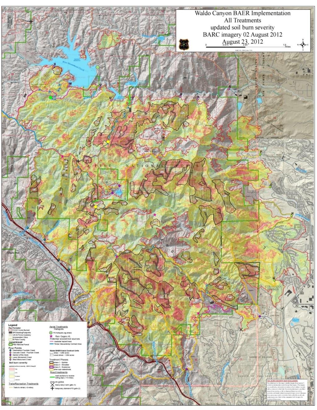
136 119
137 120 B. Power Requirement Variation for Each Concept over Each Mission Profile. For each mission profile the power requirement associated to each concept has been estimated. It can be seen that the tiltrotor behaves in a significantly different manner than all sort of helicopters. These graphs also illustrate the variety of constraints imposed on each mission profile. Then from the power requirement, the fuel consumption and therefore the weight evolution of the rotorcraft can be deduced.
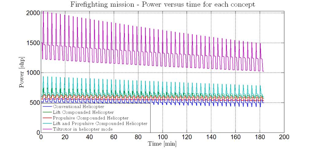
138 121
Preface. Acknowledgments. List of Tables. Nomenclature: organizations. Nomenclature: acronyms. Nomenclature: main symbols. Nomenclature: Greek symbols
 Contents Preface Acknowledgments List of Tables Nomenclature: organizations Nomenclature: acronyms Nomenclature: main symbols Nomenclature: Greek symbols Nomenclature: subscripts/superscripts Supplements
INDIAN INSTITUTE OF TECHNOLOGY KANPUR
 INDIAN INSTITUTE OF TECHNOLOGY KANPUR INDIAN INSTITUTE OF TECHNOLOGY KANPUR Removable, Low Noise, High Speed Tip Shape Tractor Configuration, Cant angle, Low Maintainence Hingelesss, Good Manoeuverability,
Performance of Advanced Heavy-Lift, High-Speed Rotorcraft Configurations
 Performance of Advanced Heavy-Lift, High-Speed Rotorcraft Configurations Wayne Johnson*, Hyeonsoo Yeo**, and C.W. Acree, Jr.* *Aeromechanics Branch, NASA **Aeroflightdynamics Directorate (AMRDEC), U.S.
The following slideshow and talk were presented at the Uber Elevate Summit on April 25 th, The text included here is an approximate transcript
 The following slideshow and talk were presented at the Uber Elevate Summit on April 25 th, 2017. The text included here is an approximate transcript of the speech given by Jay Carter, founder and CEO of
Design Considerations for Stability: Civil Aircraft
 Design Considerations for Stability: Civil Aircraft From the discussion on aircraft behavior in a small disturbance, it is clear that both aircraft geometry and mass distribution are important in the design
Tilt-rotor Ducted Fans and their Applications
 Tilt-rotor Ducted Fans and their Applications Jacob A. Wilroy University of Alabama, Tuscaloosa, AL 35487 Introduction Ducted fans are capable of producing more efficient thrust, as well as decreasing
Robot Dynamics Rotary Wing UAS: Introduction, Mechanical Design and Aerodynamics
 Robot Dynamics Rotary Wing UAS: Introduction, Mechanical Design and Aerodynamics 151-0851-00 V Marco Hutter, Michael Blösch, Roland Siegwart, Konrad Rudin and Thomas Stastny Robot Dynamics: Rotary Wing
A CFD-Based Approach to Coaxial Rotor Hover Performance Using Actuator Disks. Jonathan Chiew
 A CFD-Based Approach to Coaxial Rotor Hover Performance Using Actuator Disks Jonathan Chiew AE4699 - Spring 007 Dr. Lakshmi Sankar Georgia Institute of Technology Table of Contents Table of Contents Introduction
Appenidix E: Freewing MAE UAV analysis
 Appenidix E: Freewing MAE UAV analysis The vehicle summary is presented in the form of plots and descriptive text. Two alternative mission altitudes were analyzed and both meet the desired mission duration.
High aspect ratio for high endurance. Mechanical simplicity. Low empty weight. STOVL or STOL capability. And for the propulsion system:
 Idealized tilt-thrust (U) All of the UAV options that we've been able to analyze suffer from some deficiency. A diesel, fixed-wing UAV could possibly satisfy the range and endurance objectives, but integration
AE 451 Aeronautical Engineering Design Final Examination. Instructor: Prof. Dr. Serkan ÖZGEN Date:
 Instructor: Prof. Dr. Serkan ÖZGEN Date: 11.01.2012 1. a) (8 pts) In what aspects an instantaneous turn performance is different from sustained turn? b) (8 pts) A low wing loading will always increase
Designing evtol for the Mission NDARC NASA Design and Analysis of Rotorcraft. Wayne Johnson From VTOL to evtol Workshop May 24, 2018
 Designing evtol for the Mission NDARC NASA Design and Analysis of Rotorcraft Wayne Johnson From VTOL to evtol Workshop May 24, 2018 1 Conceptual Design of evtol Aircraft Conceptual design Define aircraft
INVESTIGATION OF ICING EFFECTS ON AERODYNAMIC CHARACTERISTICS OF AIRCRAFT AT TSAGI
 INVESTIGATION OF ICING EFFECTS ON AERODYNAMIC CHARACTERISTICS OF AIRCRAFT AT TSAGI Andreev G.T., Bogatyrev V.V. Central AeroHydrodynamic Institute (TsAGI) Abstract Investigation of icing effects on aerodynamic
Innovating the future of disaster relief
 Innovating the future of disaster relief American Helicopter Society International 33rd Annual Student Design Competition Graduate Student Team Submission VEHICLE OVERVIEW FOUR VIEW DRAWING INTERNAL COMPONENTS
DESIGN OF AN ARMAMENT WING FOR A LIGHT CATEGORY HELICOPTER
 International Journal of Engineering Applied Sciences and Technology, 7 Published Online February-March 7 in IJEAST (http://www.ijeast.com) DESIGN OF AN ARMAMENT WING FOR A LIGHT CATEGORY HELICOPTER Miss.
New Design Concept of Compound Helicopter
 New Design Concept of Compound Helicopter PRASETYO EDI, NUKMAN YUSOFF and AZNIJAR AHMAD YAZID Department of Engineering Design & Manufacture, Faculty of Engineering, University of Malaya, 50603 Kuala Lumpur,
Electric VTOL Aircraft
 Electric VTOL Aircraft Subscale Prototyping Overview Francesco Giannini fgiannini@aurora.aero 1 08 June 8 th, 2017 Contents Intro to Aurora Motivation & approach for the full-scale vehicle Technical challenges
AN ADVANCED COUNTER-ROTATING DISK WING AIRCRAFT CONCEPT Program Update. Presented to NIAC By Carl Grant November 9th, 1999
 AN ADVANCED COUNTER-ROTATING DISK WING AIRCRAFT CONCEPT Program Update Presented to NIAC By Carl Grant November 9th, 1999 DIVERSITECH, INC. Phone: (513) 772-4447 Fax: (513) 772-4476 email: carl.grant@diversitechinc.com
International Journal of Scientific & Engineering Research, Volume 4, Issue 7, July ISSN BY B.MADHAN KUMAR
 International Journal of Scientific & Engineering Research, Volume 4, Issue 7, July-2013 485 FLYING HOVER BIKE, A SMALL AERIAL VEHICLE FOR COMMERCIAL OR. SURVEYING PURPOSES BY B.MADHAN KUMAR Department
Clean Sky 2. LifeCraft Demonstrationt (IADP RC 2 & ITDs) Consultation meetings Brussels th December 2012 OUTLINE
 Consultation meetings Brussels th December 2012 OUTLINE") Clean Sky 2 LifeCraft Demonstrationt (IADP RC 2 & ITDs) Consultation meetings Brussels 10-14 th December 2012 1 1 LifeCraft - The Compound Demo OUTLINE Presentation of the Compound R/C Concept Impact &
Clean Sky 2 LifeCraft Demonstrationt (IADP RC 2 & ITDs) Consultation meetings Brussels 10-14 th December 2012 1 1 LifeCraft - The Compound Demo OUTLINE Presentation of the Compound R/C Concept Impact &
POWER ESTIMATION FOR FOUR SEATER HELICOPTER
 Jurnal Mekanikal December 2008, No. 27, 78-90 POWER ESTIMATION FOR FOUR SEATER HELICOPTER Ahmad Azlan Shah B. Ibrahim Mohammad Nazri Mohd Jaafar * Faculty of Mechanical Engineering University Technology
How the V-22 Osprey Works
 How the V-22 Osprey Works It has long been a dream of aircraft designers to create an airplane that not only can fly long ranges at high speeds and carry heavy cargo, but can also take off, hover and land
American Helicopter Society Washington, DC 20 November 2013 Approved for Public Release
 SIKORSKY & BOEING JMR TD UPDATE American Helicopter Society Washington, DC 20 November 2013 Approved for Public Release Vertical Lift / FVL Copyright 2010 Boeing. All rights reserved. Boeing Proprietary
XIV.C. Flight Principles Engine Inoperative
 XIV.C. Flight Principles Engine Inoperative References: FAA-H-8083-3; POH/AFM Objectives The student should develop knowledge of the elements related to single engine operation. Key Elements Elements Schedule
A copy can be downloaded for personal non-commercial research or study, without prior permission or charge
 Ferguson, Kevin, and Thomson, Douglas (2014) Flight dynamics investigation of compound helicopter configurations. Journal of Aircraft. ISSN 1533-3868 Copyright 2014 American Institute of Aeronautics and
DESIGN AND DEVELOPMENT OF A MICRO AIR VEHICLE (µav) CONCEPT: PROJECT BIDULE
 CONCEPT: PROJECT BIDULE") DESIGN AND DEVELOPMENT OF A MICRO AIR VEHIE (µav) CONCEPT: PROJECT BIDULE Mr T. Spoerry, Dr K.C. Wong School of Aerospace, Mechanical and Mechatronic Engineering University of Sydney NSW 6 Abstract This
DESIGN AND DEVELOPMENT OF A MICRO AIR VEHIE (µav) CONCEPT: PROJECT BIDULE Mr T. Spoerry, Dr K.C. Wong School of Aerospace, Mechanical and Mechatronic Engineering University of Sydney NSW 6 Abstract This
THE ANALYSIS OF WING PERFORMANCE FOR RECONNAISSANCE UAV ZULKIFLI BIN YUSOF UNIVERSITI MALAYSIA PAHANG
 THE ANALYSIS OF WING PERFORMANCE FOR RECONNAISSANCE UAV ZULKIFLI BIN YUSOF UNIVERSITI MALAYSIA PAHANG The Analysis of Wing Performance for Reconnaissance UAV ZULKIFLI BIN YUSOF Report submitted in partial
Power Estimation for a Two Seater Helicopter
 Power Estimation for a Two Seater Helicopter JTSE Mohammad Nazri Mohd Jaafar, a,* Mohd Idham Mohd Nayan, a M.S.A. Ishak, b a Department of Aeronautical Engineering, Faculty of Mechanical Engineering, Universiti
AIRCRAFT DESIGN SUBSONIC JET TRANSPORT
 AIRCRAFT DESIGN SUBSONIC JET TRANSPORT Analyzed by: Jin Mok Professor: Dr. R.H. Liebeck Date: June 6, 2014 1 Abstract The purpose of this report is to design the results of a given specification and to
Propeller Blade Bearings for Aircraft Open Rotor Engine
 NTN TECHNICAL REVIEW No.84(2016) [ New Product ] Guillaume LEFORT* The Propeller Blade Bearings for Open Rotor Engine SAGE2 were developed by NTN-SNR in the frame of the Clean Sky aerospace programme.
A Technical Essay on the Gyroplane
 A Technical Essay on the Gyroplane Anand Saxena * Abstract A study of "Gyroplane" and its historical evolution, general characteristics, flight characteristics, various designs, potential applications
Economic Impact of Derated Climb on Large Commercial Engines
 Economic Impact of Derated Climb on Large Commercial Engines Article 8 Rick Donaldson, Dan Fischer, John Gough, Mike Rysz GE This article is presented as part of the 2007 Boeing Performance and Flight
Part II. HISTORICAL AND ENGINEERING ANALYSIS OF AIRSHIP PLAN-AND- DESIGN AND SERVICE DECISIONS
 CONTENTS MONOGRAPHER S FOREWORD DEFENITIONS, SYMBOLS, ABBREVIATIONS, AND INDICES Part I. LAWS AND RULES OF AEROSTATIC FLIGHT PRINCIPLE Chapter 1. AIRCRAFT FLIGHT PRINCIPLE 1.1 Flight Principle Classification
HELICOPTER TAIL ROTOR ANALYSIS: EXPERIENCE IN AGUSTA WITH ADAMS
 HELICOPTER TAIL ROTOR ANALYSIS: EXPERIENCE IN AGUSTA WITH ADAMS Bianchi F., Agusta Sp.a. Via G.Agusta, 520 - Cascina Costa di Samarate,Varese - Italy - e-mail: atr@agusta.it Abstract The purpose of the
Aerodynamic Testing of the A400M at ARA. Ian Burns and Bryan Millard
 Aerodynamic Testing of the A400M at ARA by Ian Burns and Bryan Millard Aircraft Research Association Bedford, England Independent non-profit distributing research and development organisation Set up in
Jay Gundlach AIAA EDUCATION SERIES. Manassas, Virginia. Joseph A. Schetz, Editor-in-Chief. Blacksburg, Virginia. Aurora Flight Sciences
 Jay Gundlach Aurora Flight Sciences Manassas, Virginia AIAA EDUCATION SERIES Joseph A. Schetz, Editor-in-Chief Virginia Polytechnic Institute and State University Blacksburg, Virginia Published by the
EXPERIMENTAL RESEARCH ON HELICOPTER TAIL SHAKE PHENOMENON
 EXPERIMENTAL RESEARCH ON HELICOPTER TAIL SHAKE PHENOMENON Iskandar Shah Ishak, Shuhaimi Mansor, Tholudin Mat Lazim Department of Aeronautical Engineering, Faculty of Mechanical Engineering, Universiti
Wind Tunnel Measurement Of Aerodynamic Characteristics Of A Generic Eurocopter Helicopter
 Wind Tunnel Measurement Of Aerodynamic Characteristics Of A Generic Eurocopter Helicopter by Engr. Assoc. Prof. Dr Shuhaimi Mansor, MIEM, P. Eng. Experimental aerodynamic studies on a generic model of
Performance means how fast will it go? How fast will it climb? How quickly it will take-off and land? How far it will go?
 Performance Concepts Speaker: Randall L. Brookhiser Performance means how fast will it go? How fast will it climb? How quickly it will take-off and land? How far it will go? Let s start with the phase
Flight Test Evaluation of C-130H Aircraft Performance with NP2000 Propellers
 Flight Test Evaluation of C-130H Aircraft Performance with NP2000 Propellers Lance Bays Lockheed Martin - C-130 Flight Sciences Telephone: (770) 494-8341 E-Mail: lance.bays@lmco.com Introduction Flight
Environmentally Focused Aircraft: Regional Aircraft Study
 Environmentally Focused Aircraft: Regional Aircraft Study Sid Banerjee Advanced Design Product Development Engineering, Aerospace Bombardier International Workshop on Aviation and Climate Change May 18-20,
Key Drivers for evtol Design Christopher Silva From VTOL to evtol Workshop May 24, 2018
 Key Drivers for evtol Design Christopher Silva From VTOL to evtol Workshop May 24, 2018 Can we use what we already know? Techniques and processes Aircraft / System design theory: Design Thinking, MDAO,
Aerodynamics & Flight Mechanics Research Group
 Aerodynamics & Flight Mechanics Research Group Methods of Calculating Helicopter Power, Fuel Consumption and Mission Performance S. J. Newman Technical Report AFM-11/07 January 2011 UNIVERSITY OF SOUTHAMPTON
31 st Annual American Helicopter Society Student Design Competition: Graduate Submission
 Rotorcraft Adaptive and Morphing Structures Lab The Emperor UAV: Executive Summary George Jacobellis Alex Angilella Jean-Paul Reddinger Andrew Howard Matthew Misiorowski Michael Pontecorvo Jayanth Krishnamurthi
ECO-CARGO AIRCRAFT. ISSN: International Journal of Science, Engineering and Technology Research (IJSETR) Volume 1, Issue 2, August 2012
 Volume 1, Issue 2, August 2012") ECO-CARGO AIRCRAFT Vikrant Goyal, Pankhuri Arora Abstract- The evolution in aircraft industry has brought to us many new aircraft designs. Each and every new design is a step towards a greener tomorrow.
ECO-CARGO AIRCRAFT Vikrant Goyal, Pankhuri Arora Abstract- The evolution in aircraft industry has brought to us many new aircraft designs. Each and every new design is a step towards a greener tomorrow.
The Airplane That Could!
 The Airplane That Could! Critical Design Review December 6 th, 2008 Haoyun Fu Suzanne Lessack Andrew McArthur Nicholas Rooney Jin Yan Yang Yang Agenda Criteria Preliminary Designs Down Selection Features
CHAPTER 1. Introduction and Literature Review
 CHAPTER 1 Introduction and Literature Review 1.1 Introduction The Active Magnetic Bearing (AMB) is a device that uses electromagnetic forces to support a rotor without mechanical contact. The AMB offers
Propeller blade shapes
 31 1 Propeller blade shapes and Propeller Tutorials 2 Typical Propeller Blade Shape 3 M Flight M. No. Transonic Propeller Airfoil 4 Modern 8-bladed propeller with transonic airfoils near the tip and swept
The European Tilt Rotor-Status of ERICA Design and Test Activities. Madrid, 31 March 2011
 The European Tilt Rotor-Status of ERICA Design and Test Activities Alessandro Stabellini NICETRIP Project Manager TILTROTOR RESEARCH IN EUROPE Handling Qualities requirements background Flight Control
How Do Helicopters Fly? An Introduction to Rotor Aeromechanics
 Audience: Grades 9-10 Module duration: 75 minutes How Do Helicopters Fly? An Introduction to Rotor Aeromechanics Instructor Guide Concepts: Airfoil lift, angle of attack, rotary wing aerodynamics, hover
Multidisciplinary Design Optimization of a Truss-Braced Wing Aircraft with Tip-Mounted Engines
 Multidisciplinary Design Optimization of a Truss-Braced Wing Aircraft with Tip-Mounted Engines NASA Design MAD Center Advisory Board Meeting, November 14, 1997 Students: J.M. Grasmeyer, A. Naghshineh-Pour,
Evaluation of the Applicability of the Vortex Lattice Method to the Analysis of Human Powered Aircraft
 McNair Scholars Research Journal Volume Article Evaluation of the Applicability of the Vortex Lattice Method to the Analysis of Human Powered Aircraft Armando R. Collazo Garcia III Embry-Riddle Aeronautical
Chapter 10 Miscellaneous topics - 2 Lecture 39 Topics
 Chapter 10 Miscellaneous topics - 2 Lecture 39 Topics 10.3 Presentation of results 10.3.1 Presentation of results of a student project 10.3.2 A typical brochure 10.3 Presentation of results At the end
The Pennsylvania State University. The Graduate School. Department of Aerospace Engineering TILTROTOR PERFORMANCE IMPROVEMENTS THROUGH
 The Pennsylvania State University The Graduate School Department of Aerospace Engineering TILTROTOR PERFORMANCE IMPROVEMENTS THROUGH THE USE OF SPAN EXTENSIONS AND WINGLETS A Thesis in Aerospace Engineering
Reducing Landing Distance
 Reducing Landing Distance I've been wondering about thrust reversers, how many kinds are there and which are the most effective? I am having a debate as to whether airplane engines reverse, or does something
DEVELOPMENT OF A CARGO AIRCRAFT, AN OVERVIEW OF THE PRELIMINARY AERODYNAMIC DESIGN PHASE
 ICAS 2000 CONGRESS DEVELOPMENT OF A CARGO AIRCRAFT, AN OVERVIEW OF THE PRELIMINARY AERODYNAMIC DESIGN PHASE S. Tsach, S. Bauminger, M. Levin, D. Penn and T. Rubin Engineering center Israel Aircraft Industries
Y. Lemmens, T. Benoit, J. de Boer, T. Olbrechts LMS, A Siemens Business. Real-time Mechanism and System Simulation To Support Flight Simulators
 Y. Lemmens, T. Benoit, J. de Boer, T. Olbrechts LMS, A Siemens Business Real-time Mechanism and System Simulation To Support Flight Simulators Smarter decisions, better products. Contents Introduction
AERONAUTICAL ENGINEERING
 AERONAUTICAL ENGINEERING SHIBIN MOHAMED Asst. Professor Dept. of Mechanical Engineering Al Ameen Engineering College Al- Ameen Engg. College 1 Aerodynamics-Basics These fundamental basics first must be
Special Condition C-04 on Interaction of Systems and Structure on helicopters configured with Fly-by-Wire (FBW) Flight Control System (FCS)
 Flight Control System (FCS)") Special Condition C-04 on Interaction of Systems and Structure on helicopters configured with Fly-by-Wire (FBW) Flight Control System (FCS) This Special Condition is published for public consultation in
Special Condition C-04 on Interaction of Systems and Structure on helicopters configured with Fly-by-Wire (FBW) Flight Control System (FCS) This Special Condition is published for public consultation in
Product Comparison. 480B vs. Robinson R44
 Product Comparison 480B vs. Robinson R44 480B vs. Robinson R44 Specifications Enstrom 480B Robinson R44 Seats 1/4 or 2/1 1/3 Continuous Engine Power (To Drivetrain) 277 shp/206 kw 205 shp/183 kw Gross
AIAA Foundation Undergraduate Team Aircraft Design Competition. RFP: Cruise Missile Carrier
 AIAA Foundation Undergraduate Team Aircraft Design Competition RFP: Cruise Missile Carrier 1999/2000 AIAA FOUNDATION Undergraduate Team Aircraft Design Competition I. RULES 1. All groups of three to ten
On-Demand Mobility Electric Propulsion Roadmap
 On-Demand Mobility Electric Propulsion Roadmap Mark Moore, ODM Senior Advisor NASA Langley Research Center EAA AirVenture, Oshkosh July 22, 2015 NASA Distributed Electric Propulsion Research Rapid, early
SIMULATION OF PROPELLER EFFECT IN WIND TUNNEL
 SIMULATION OF PROPELLER EFFECT IN WIND TUNNEL J. Červinka*, R. Kulhánek*, Z. Pátek*, V. Kumar** *VZLÚ - Aerospace Research and Test Establishment, Praha, Czech Republic **C-CADD, CSIR-NAL, Bangalore, India
A Computational Study of Axial Compressor Rotor Casing Treatments and Stator Land Seals
 Virginia Commonwealth University VCU Scholars Compass Theses and Dissertations Graduate School 2006 A Computational Study of Axial Compressor Rotor Casing Treatments and Stator Land Seals Charles C. Cates
A practical investigation of the factors affecting lift produced by multi-rotor aircraft. Aaron Bonnell-Kangas
 A practical investigation of the factors affecting lift produced by multi-rotor aircraft Aaron Bonnell-Kangas Bonnell-Kangas i Table of Contents Introduction! 1 Research question! 1 Background! 1 Definitions!
AT-10 Electric/HF Hybrid VTOL UAS
 AT-10 Electric/HF Hybrid VTOL UAS Acuity Technologies Robert Clark bob@acuitytx.com Summary The AT-10 is a tactical size hybrid propulsion VTOL UAS with a nose camera mount and a large payload bay. Propulsion
HIGHSPEED ROTORCRAFT OF THE MI-450 FAMILY А NEW GENERATION OF CROSS ARRANGEMENT ROTARY WING AIRCRAFT
 HIGHSPEED ROTORCRAFT OF THE MI-450 FAMILY А NEW GENERATION OF CROSS ARRANGEMENT ROTARY WING AIRCRAFT Mikhail Korotkevich, Stanislav Midzyanovskiy, Valery Ivchin JSC Moscow Mil Helicopter Plant, 140070,
This is the author s final accepted version.
 Han, D. and Barakos, G.N. (2017) Variable-speed tail rotors for helicopters with variable-speed main rotors. Aeronautical Journal, 121(1238), pp. 433-448. (doi:10.1017/aer.2017.4) This is the author s
Performance and Design Investigation of Heavy Lift Tilt-Rotor with Aerodynamic Interference Effects
 JOURNAL OF AIRCRAFT Vol. 46, No. 4, July August 29 Performance and Design Investigation of Heavy Lift Tilt-Rotor with Aerodynamic Interference Effects Hyeonsoo Yeo and Wayne Johnson NASA Ames Research
COMPUTATIONAL ANALYSIS OF TWO DIMENSIONAL FLOWS ON A CONVERTIBLE CAR ROOF ABDULLAH B. MUHAMAD NAWI
 COMPUTATIONAL ANALYSIS OF TWO DIMENSIONAL FLOWS ON A CONVERTIBLE CAR ROOF ABDULLAH B. MUHAMAD NAWI Report submitted in partial of the requirements for the award of the degree of Bachelor of Mechanical
Powertrain Design for Hand- Launchable Long Endurance Unmanned Aerial Vehicles
 Powertrain Design for Hand- Launchable Long Endurance Unmanned Aerial Vehicles Stuart Boland Derek Keen 1 Justin Nelson Brian Taylor Nick Wagner Dr. Thomas Bradley 47 th AIAA/ASME/SAE/ASEE JPC Outline
(12) United States Patent
 United States Patent") (12) United States Patent USOO9284.05OB2 (10) Patent No.: US 9.284,050 B2 Bagai (45) Date of Patent: Mar. 15, 2016 (54) AIRFOIL FOR ROTOR BLADE WITH (56) References Cited REDUCED PITCHING MOMENT U.S. PATENT
(12) United States Patent USOO9284.05OB2 (10) Patent No.: US 9.284,050 B2 Bagai (45) Date of Patent: Mar. 15, 2016 (54) AIRFOIL FOR ROTOR BLADE WITH (56) References Cited REDUCED PITCHING MOMENT U.S. PATENT
Systems Group (Summer 2012) 4 th Year (B.Eng) Aerospace Engineering Candidate Carleton University, Ottawa,Canada Mail:
 4 th Year (B.Eng) Aerospace Engineering Candidate Carleton University, Ottawa,Canada Mail:") Memo Airport2030_M_Family_Concepts_of_Box_Wing_12-08-10.pdf Date: 12-08-10 From: Sameer Ahmed Intern at Aero Aircraft Design and Systems Group (Summer 2012) 4 th Year (B.Eng) Aerospace Engineering Candidate
Memo Airport2030_M_Family_Concepts_of_Box_Wing_12-08-10.pdf Date: 12-08-10 From: Sameer Ahmed Intern at Aero Aircraft Design and Systems Group (Summer 2012) 4 th Year (B.Eng) Aerospace Engineering Candidate
Lip wing Lift at zero speed
 Lip wing Lift at zero speed Dusan Stan, July 2014 http://hypertriangle.com/lipwing.php dusan.stan@hypertriangle.com HyperTriangle 2014 Lip_wing_Lift_at_zero_speed_R2.doc Page 1 of 7 1. Introduction There
The Pennsylvania State University. The Graduate School ACOUSTIC ANALYSIS OF COMPOUND HELICOPTERS WITH TRIM VARIATIONS. A Thesis in
 The Pennsylvania State University The Graduate School ACOUSTIC ANALYSIS OF COMPOUND HELICOPTERS WITH TRIM VARIATIONS A Thesis in Aerospace Engineering by Heather Marie Barron 2013 Heather Marie Barron
Is Low Friction Efficient?
 Is Low Friction Efficient? Assessment of Bearing Concepts During the Design Phase Dipl.-Wirtsch.-Ing. Mark Dudziak; Schaeffler Trading (Shanghai) Co. Ltd., Shanghai, China Dipl.-Ing. (TH) Andreas Krome,
Research Report ZETJET-Aircraft Engines
 Research Report ZETJET-Aircraft Engines aviation can reduce cost of transport by up to 70% UAV 1 click picture for video test rig click picture for video UAV 2- click picture for video ZETJET AG Bahnhofplatz
Product Comparison. F28F vs. Robinson R44
 Product Comparison F28F vs. Robinson R44 F28F vs. R44 Specs Seats ENSTROM F28F ROBINSON R44 II 3 4 Continuous Engine Power (To Drivetrain) (hp) 225 205 Turbo-Charged? YES Empty Weight (As Configured )
AIRCRAFT AND TECHNOLOGY CONCEPTS FOR AN N+3 SUBSONIC TRANSPORT. Elena de la Rosa Blanco May 27, 2010
 AIRCRAFT AND TECHNOLOGY CONCEPTS FOR AN N+3 SUBSONIC TRANSPORT MIT, Aurora Flights Science, and Pratt & Whitney Elena de la Rosa Blanco May 27, 2010 1 The information in this document should not be disclosed
Electric Drive - Magnetic Suspension Rotorcraft Technologies
 Electric Drive - Suspension Rotorcraft Technologies William Nunnally Chief Scientist SunLase, Inc. Sapulpa, OK 74066-6032 wcn.sunlase@gmail.com ABSTRACT The recent advances in electromagnetic technologies
ELECTRIC POWER TRAINS THE KEY ENABLER FOR CONTRA ROTATING PROPELLERS IN GENERAL AVIATION (& VICE VERSA)
") ELECTRIC POWER TRAINS THE KEY ENABLER FOR CONTRA ROTATING PROPELLERS IN GENERAL AVIATION (& VICE VERSA) ATI D3 EVENT 8 TH MAY 2018 THE EMERGENCE OF ELECTRIFICATION IN AEROSPACE NICK SILLS, CONTRA ELECTRIC
ELECTRIC POWER TRAINS THE KEY ENABLER FOR CONTRA ROTATING PROPELLERS IN GENERAL AVIATION (& VICE VERSA) ATI D3 EVENT 8 TH MAY 2018 THE EMERGENCE OF ELECTRIFICATION IN AEROSPACE NICK SILLS, CONTRA ELECTRIC
Facts, Fun and Fallacies about Fin-less Model Rocket Design
 Facts, Fun and Fallacies about Fin-less Model Rocket Design Introduction Fin-less model rocket design has long been a subject of debate among rocketeers wishing to build and fly true scale models of space
CONCEPTUAL DESIGN OF ECOLOGICAL AIRCRAFT FOR COMMUTER AIR TRANSPORTATION
 26 TH INTERNATIONAL CONGRESS OF THE AERONAUTICAL SCIENCES CONCEPTUAL DESIGN OF ECOLOGICAL AIRCRAFT FOR COMMUTER AIR TRANSPORTATION Yasuhiro TANI, Tomoe YAYAMA, Jun-Ichiro HASHIMOTO and Shigeru ASO Department
CarterCopters. Cleaner Greener. Safer. Your affordable environmentally-friendly VTOL technology Carter Aviation Technologies, LLC
 CarterCopters Cleaner Greener Your affordable environmentally-friendly VTOL technology Safer 2018 Carter Aviation Technologies, LLC Carter Aviation Is a green VTOL possible? Genesis & Mission: The company
(12) Patent Application Publication (10) Pub. No.: US 2010/ A1
 Patent Application Publication (10) Pub. No.: US 2010/ A1") (19) United States (12) Patent Application Publication (10) Pub. No.: US 2010/0044499 A1 Dragan et al. US 20100.044499A1 (43) Pub. Date: Feb. 25, 2010 (54) (75) (73) (21) (22) SIX ROTOR HELICOPTER Inventors:
(19) United States (12) Patent Application Publication (10) Pub. No.: US 2010/0044499 A1 Dragan et al. US 20100.044499A1 (43) Pub. Date: Feb. 25, 2010 (54) (75) (73) (21) (22) SIX ROTOR HELICOPTER Inventors:
1/10 th Scale Model Tests of a Centre-line Tiltrotor:
 1/10 th Scale Model Tests of a Centre-line Tiltrotor: Conversion between rotary and fixed wing modes Bob Burrage Director Rotorcraft Operations Ltd., Oxfordshire, United Kingdom bob.burrage@ntlworld.com
A Game of Two: Airbus vs Boeing. The Big Guys. by Valerio Viti. Valerio Viti, AOE4984, Project #1, March 22nd, 2001
 A Game of Two: Airbus vs Boeing The Big Guys by Valerio Viti 1 Why do we Need More Airliners in the Next 20 Years? Both Boeing and Airbus agree that civil air transport will keep increasing at a steady
Die Lösungen müssen manuell überpüft werden. Die Buchstaben stimmen nicht mehr überein.
 HELI Final Test 2015, Winterthur 17.06.2015 NAME: Mark the best answer. A B C D A B C D Die Lösungen müssen manuell überpüft werden. Die Buchstaben stimmen nicht mehr überein. 1 1 Principles of Flight
Chapter 10 Parametric Studies
 Chapter 10 Parametric Studies 10.1. Introduction The emergence of the next-generation high-capacity commercial transports [51 and 52] provides an excellent opportunity to demonstrate the capability of
7. PRELIMINARY DESIGN OF A SINGLE AISLE MEDIUM RANGE AIRCRAFT
 7. PRELIMINARY DESIGN OF A SINGLE AISLE MEDIUM RANGE AIRCRAFT Students: R.M. Bosma, T. Desmet, I.D. Dountchev, S. Halim, M. Janssen, A.G. Nammensma, M.F.A.L.M. Rommens, P.J.W. Saat, G. van der Wolf Project
Airship Technology. G. A. Khoury. J. D. Gillett Formerly of Brunei University and The Airship Association CAMBRIDGE UNIVERSITY PRESS
 - uirf Airship Technology G. A. Khoury Imperial College, London, and The Airship Association J. D. Gillett Formerly of Brunei University and The Airship Association CAMBRIDGE UNIVERSITY PRESS Contents
The Sonic Cruiser A Concept Analysis
 International Symposium "Aviation Technologies of the XXI Century: New Aircraft Concepts and Flight Simulation", 7-8 May 2002 Aviation Salon ILA-2002, Berlin The Sonic Cruiser A Concept Analysis Dr. Martin
Development of an Advanced Rotorcraft Preliminary Design Framework
 134 Int l J. of Aeronautical & Space Sciences, Vol. 10, No. 2, November 2009 Development of an Advanced Rotorcraft Preliminary Design Framework Jaehoon Lim* and SangJoon Shin** School of Mechanical and
New Design Approach of Compound Helicopter
 New Design Approach of Compound Helicopter PRASETYO EDI, NUKMAN YUSOFF and AZNIJAR AHMAD YAZID Department of Engineering Design & Manufacture, Faculty of Engineering, University of Malaya, 50603 Kuala
PROJECT PORTFOLIO. A list of projects completed by Sukra Helitek and their briefs Sukra Helitek 1 P a g e 33
 PROJECT PORTFOLIO A list of projects completed by Sukra Helitek and their briefs 2017 Sukra Helitek 1 P a g e 33 contact@sukra-helitek.com OUR VALUABLE CUSTOMERS 2017 Sukra Helitek 2 P a g e 33 contact@sukra-helitek.com
10th Australian International Aerospace Congress
 AUSTRALIAN INTERNATIONAL AEROSPACE CONGRESS Paper presented at the 10th Australian International Aerospace Congress incorporating the 14th National Space Engineering Symposium 2003 29 July 1 August 2003
Full-Scale 1903 Wright Flyer Wind Tunnel Test Results From the NASA Ames Research Center
 Full-Scale 1903 Wright Flyer Wind Tunnel Test Results From the NASA Ames Research Center Henry R. Jex, Jex Enterprises, Santa Monica, CA Richard Grimm, Northridge, CA John Latz, Lockheed Martin Skunk Works,
Primary control surface design for BWB aircraft
 Primary control surface design for BWB aircraft 4 th Symposium on Collaboration in Aircraft Design 2014 Dr. ir. Mark Voskuijl, ir. Stephen M. Waters, ir. Crispijn Huijts Challenge Multiple redundant control
SILENT SUPERSONIC TECHNOLOGY DEMONSTRATION PROGRAM
 25 TH INTERNATIONAL CONGRESS OF THE AERONAUTICAL SCIENCES SILENT SUPERSONIC TECHNOLOGY DEMONSTRATION PROGRAM Akira Murakami* *Japan Aerospace Exploration Agency Keywords: Supersonic, Flight experiment,
V-280 Valor Joint Multi-Role Technology Demonstrator
 This research was partially funded by the Government under agreement No. W911W6-13-2-0001. The U.S. Government is authorized to reproduce and distribute reprints for Government purposes notwithstanding