HELICOPTER TAIL ROTOR ANALYSIS: EXPERIENCE IN AGUSTA WITH ADAMS
|
|
|
- Daniella Summers
- 5 years ago
- Views:
Transcription
1 HELICOPTER TAIL ROTOR ANALYSIS: EXPERIENCE IN AGUSTA WITH ADAMS Bianchi F., Agusta Sp.a. Via G.Agusta, Cascina Costa di Samarate,Varese - Italy - atr@agusta.it Abstract The purpose of the present paper is to illustrate some major results obtained from the dynamic simulation of a partially flexible tail rotor model of an Agusta helicopter. The aim is to investigate the features of ADAMS as a mechanical system simulation tool with an application to a case of interest for Agusta. 1. Introduction The numerical modeling of a mechanical system able to describe its dynamic and kinematic behavior continuously with the time, appears as a powerful tool to acquire a deeper knowledge of how the single components work. Namely it might help to recognize and evaluate the load paths to better understand what they are and how they change depending, for instance, on different (i.e. time varying) configurations and initial or boundary conditions. Especially for a complex mechanical system like a helicopter rotor, such a modeling might offer the opportunity of exploring and testing various operating and even unusual or extreme conditions for which experimental testing would require high costs and also long times. On the other hand, however, it is understandable that the degree of confidence we can put in such a simulation depends on its validation / correlation by experimental data. That is, physical testing allows to validate the accuracy of the simulation results. The correlated model presents itself also as a powerful mean of planning experimental tests, pointing out, for instance, configurations which are more critical than others and that are then worthy to be tested. A multibody approach based program like ADAMS is quite suitable for this aim as, just to mention the most evident features in this sense, it is capable to manage a detailed structural and kinematic modeling of systems including parts connected together by means of dampers, hinges, sleeves, and other similar kinds of joints. Moreover, considering the complexity of the dynamics and the aerodynamics of a helicopter rotor (blade flexibility, unsteady aerodynamic loading) ADAMS offers the possibility of introducing structural flexibility interfacing well with widely used FEA programs and also allows an extensive use of user-written subroutines for the aerodynamic simulation. The present paper is focused on the following subject. The origin of the work here presented has to be related to the intention to introduce in Agusta a new software having the capacities of ADAMS, exploring the features which were thought to well integrate the simulation tools extensively used at present in Agusta. In this context some significant results are illustrated coming from the dynamic simulation of the tail rotor of an Agusta helicopter. Furthermore a particular tail rotor subsystem which will be subjected to experimental testing in the next future, is considered, reproducing the experimental setting. The first aim is to explore
2 different configurations of the system in order to put into evidence the most critical or significant one. In this context, as aforementioned, an experimental validation is necessary, but, as a first step anticipating the test results, just a numeric investigation is presented. The paper is organised as follows: after a short introduction describing a helicopter tail rotor and its major features (dynamics, aerodynamics and mechanics) (Section 2); Section 3 is focused on the main characteristics of the complete tail rotor model. Section 4 illustrates the major results obtained from the dynamic simulation; similarly Section 5 presents the tail rotor subsystem model and some results. Finally in Section 6 there are some concludings and remarks. 2. Tail rotor main features 2.1 Rotor dynamics and aerodynamics The tail rotor of a helicopter is placed at the rear end of the fuselage; its main function is to develop the force required to counter the torque acting on the vehicle as a consequence of the torque provided to keep the main rotor rotating. Moments and forces generated by the tail rotor also permit helicopter control and maneuvering. The tail rotor presented here is a fully articulated type, that is each blade is connected to the rotor s central hub by a set of hinges, which allow movement: out of the rotor disk plane (outwards and inwards, flapping motion) in the disk plane (rearwards and forwards, lagging motion) around its longitudinal, or feathering axis (pitching or feathering motion) Generally speaking, the tail rotor hub rotates at an almost constant angular rate, as the result of the torque provided by the engines through a gear train, which receives the power from the main rotor gear train. The pilot can control the thrust force generated by the tail rotor by varying the collective pitch angle of the blades; this happens through a control chain ending at the rotor with a servoactuator operating system which consists basically of a control rod able to move outwards and inwards; this causes an increase or a decrease of the blades pitch, depending on the features of the installation. Briefly, the behavior of a rotor can be considered as essentially dominated by four phenomena; Fig.1 shows schematically what they are and how they influence one another.
3 Induced flow Incidence and velocity Main rotor influence Fin blockage Control inputs Aerodynamic loads Rotor and blade dynamics Control system Fig. 1 - Rotor dynamics and aerodynamics The figure puts into evidence the interaction between dynamics and aerodynamics: the control inputs influence directly the aerodynamic loads acting on the blade, which, in turn, act as forcing inputs for the rotor and blade dynamics (both rigid body and elastic modes for the blade and gyroscopic phenomena like precession); the loop is closed by taking into account the effects of blade motion and induced flow on the aerodynamic behavior of the blade lifting surface. Moreover, the tail rotor is not an isolated system, but is subjected to the influence of the fuselage (structural dynamics, fin blockage) and of the main rotor (wake effects). It should be clear from the above brief description how complex and ambitious is modeling a helicopter rotor behavior in all its aspects. 2.2 Mechanical and functional description The tail rotor assembly (Fig.2) is made up of a mast, hub, two scissors assemblies, four pitch control rods, slider, spider, four dampers, four blades and control (extension) rod. The hub allows the connection of the four blades. The four pitch control rods are connected to the blades at one end and to the spider forked arms at the other end. The dampers are connected to the blades at one end and to the hub at the other end. All the aforementioned components, except the extension rod, are rotating parts.
4 BLADE SPIDER SLIDER PITCH CONTROL ROD SCISSORS ASSY DAMPER MAST EXTENSION ROD Fig. 2 - Tail rotor assembly From a mechanical point of view the functions of the tail rotor main components can be described as follows. The power provided to the tail rotor by the gear train is transmitted to the rotor hub by the mast. The variation of the collective pitch of the blades for the thrust control is possible due to a translational movement (inwards and outwards) of the four pitch control rods. The spider-slider assembly rotates together with the hub-blades system and translates together with the extension rod, which is moved by a servoactuator system. The two scissors assemblies keep the spider-slider assembly rotating together with the hub. The dampers have the function of damping the lag movement. 3. ADAMS model description As anticipated in the introduction of the present paper, the aim of a multibody modeling of the tail rotor of an Agusta helicopter is to investigate the features of ADAMS as a mechanical system simulation tool, through an application to a case of interest for Agusta. The attention has been focused on the following points: 1) evaluating the load sharing among the different components of the rotating control chain, during continuous time simulation, 2) analyzing the effect of flexibility of some components and
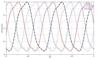
5 3) kinematic simulation. The spider, the slider, the scissors assemblies and the control rod have been modeled as flexible bodies. The blades have been modeled as rigid bodies. This was sufficient for a first evaluation of the loads acting on the control chain. The time varying trim loads (aerodynamic and inertial loads), for a certain critical flight condition, have been evaluated through the aeroelastic code CAMRAD/JA [1] and subsequently applied to each blade as concentrated forces and moments at the hinges location. Each of the four dampers has been modeled as an assembly of two rigid bodies with a suitable elastic-viscous force acting between them. The steps followed to define the final model are: kinematic behavior of a very first completely rigid model has been studied. subsequently this model has been replaced by a partially flexible one, introducing for some components their flexible representation, using I-DEAS [2] pre-processing and MSC/NASTRAN [3]. finally, the trim loads of CAMRAD/JA have been introduced in ADAMS. 4. Results 4.1 Kinematic results 1 The complete model has globally one degree of freedom, which is the rotation relative to ground about the rotor axis. A constant angular rate law (i.e. a STEP like law) has been imposed to the whole system, while a time varying law (i.e. a Fourier series like law) has been introduced for the trim aerodynamic and inertial resultant moments in flap and lag and for the flap, lag and pitch rotations; the kinematic pitch-flap coupling is also reproduced through the model geometry. Figs. 3, 4 and 5 illustrate the flap, the pitch and the lag time histories respectively, for the four blades. 1 All numerical values have been scaled with an appropriate scale factor.

6 Fig. 3 Flap movement Fig. 4 Pitch movement

7 Fig. 5 - Lag movement Fig. 6 shows the time variation of the four dampers stroke, while in Fig. 7 the results of the Fourier analysis are presented. The peaks found through this analysis are in good accordance with the known dynamic characteristics of the tail rotor system. Fig.6 Dampers stroke

8 Fig. 7 Fourier analysis of one of the dampers stroke 4.2 Load survey results It is interesting to see a comparison between the rigid and flexible cases. Fig. 8 shows the axial load of one pitch control rod, together with the load acting on the corresponding spider arm when a flexible or a rigid spider is considered. It is interesting to note the redistribution of load between the two wings, in the flexible case (equal distribution of the shear load - spider shear load left and right wings). Fig. 9 presents the Fourier analysis of the axial load of Fig. 8. Fig. 8 Comparison rigid vs. flexible

9 Fig. 9 Fourier analysis Fig. 10 illustrates the control rod axial load in both cases; it can be seen how the trend becomes smooth after a rough initial transitory phase, also numerical dependent. The signals are quite similar, but however, the control rod has a high axial stiffness. Moreover it can be seen how the main frequency is a 4x revolution, as expected. Fig. 10 Extension rod axial load: rigid vs. flexible Fig. 11 shows the stabilised signal corresponding to the T Z force (i.e. the force in the hub plane) on the upper half scissors, together with the Fourier analysis. The component frequencies have a 1x rev, a 3x rev and a 5x rev, as expected.

10 Fig. 11- T Z force on the upper half scissors (stabilized signal) Fig. 12 puts into evidence, through a Fourier analysis of the Tz force, a very high frequency that actually characterizes the transitory phase and corresponds to a high frequency torsional mode of the spider. Fig. 12- T Z force on the upper half scissors (transitory phase) Fig 13 shows a comparison flexible vs. rigid for the moments at the fitting between the slider and the mast in the hub plane.
11 Fig.13 - Slider- mast moments ( rigid vs flexible ) 5. Description of the reduced model As mentioned in the introduction, the main aim of modeling this rotor subsystem is to reproduce an experimental test setting to investigate different configurations and therefore put into evidence the most significant ones, from a structural point of view (i.e. FEA studies of individual parts). The chosen subsystem is completely flexible and includes just the slider, the spider, the control rod and the two scissors assemblies (see Fig. 14 below)
12 Fig 14 - Tail rotor reduced ADAMS model The test rig consists of four actuators fitted at the spider s arms at one end and at the rig at the other end. The system is fixed at the rig so that only the flexible modes are present. The ADAMS model reproduces the phase lagged forces of the actuators; it has one degree of freedom left which is the axial translation. A time dependent law (i.e. a multi-step like law) has been introduced in order to permit the configuration changes. At the moment no modeling of contact features such as bushings (e.g. at the fitting surfaces between the slider and the ground, that is the test rig) is present. 5.1 Results Below are presented the most important results for the upper and lower half scissors. The values are ploted as a function of the different axial positions of the control rod. As can be noted from Figs. 15 and 16 the torque and bending moment have different trends. ADAMS simulation therefore has permitted to get different loading conditions for the half scissors to be studied through a FE analysis in I-DEAS, putting into evidence the most critical loading combinations.
13 1,2 Lower half scissors Upper half scissors 1 Torque Moment (Dimensionless) 0,8 0,6 0,4 0, ,2 0,4 0,6 0,8 1 1,2 Control Rod Axial Position (Dimensionless) Fig Torque 1,2 Lower half scissors Upper half scissors 1 Bending Moment (Dimensionless) 0,8 0,6 0,4 0, ,2 0,4 0,6 0,8 1 1,2 Control rod axial position (Dimensionless) Fig Bending moment
14 1,05 Lower - upper half scissors 1 Shear force (Dimensionless) 0,95 0,9 0,85 0,8 0 0,2 0,4 0,6 0,8 1 1,2 Control rod axial position (Dimensionless) Fig Shear force 6. Conclusions First of all it is worth underlining once more that the object of the present work is the result of a very first investigation of ADAMS s features applied to a case of interest for Agusta, a tail rotor system. The results obtained from the simulations performed are satisfactory, but much work sill needs to be done in some areas and I will mention some of them below. That is, it would be of some interest to introduce, in the complete tail rotor model, flexibility for other parts, such as the pitch control rods, the mast and the hub. A further step should be to model the contacts between the slider and the mast. The trim loads (aerodynamic and inertial loads) for this application have been calculated outside ADAMS, and subsequently applied as concentrated forces on the rigid blades. A possible development could be to set up a global approach including load generation within ADAMS.
15 REFERENCES [1] CAMRAD/JA, A Comprehensive Analytical Model of Rotorcraft Aerodynamics and Dynamics, Vol. 1/2, Wayne Johnson, Johnson Aeronautics, Palo Alto, California [2] I-DEAS MASTER SERIES Modeling & Simulation User's Guide Version 6A. [3] MSC/NASTRAN User's Guides,Version 70.5 [4] ADAMS/VIEW User's Guide, Version 10., Mechanical Dynamics, 2301 Commonwealth Blvd., Ann Arbor, MI 48105, [5] ADAMS/FEA Reference Manual, Version 10., Mechanical Dynamics, 2301 Commonwealth Blvd., Ann Arbor, MI 48105, [6] Bertogalli V., Bisi F., Lovera M., Modelling helicopter rotor dynamics with ADAMS [7] Johnson W., Helicopter theory, Princeton University Press, 1981 [8] Bramwell, A. R. S., Helicopter Dynamics, Edward Arnold, 1976 [9] AA.VV., Agusta internal report on ADAMS software evaluation.
16 HELICOPTER TAIL ROTOR ANALYSIS : EXPERIENCE IN AGUSTA WITH ADAMS MODELLO DEL ROTORE DI CODA AB139 1
17 OBJECTIVE TO INVESTIGATE THE FEATURES OF ADAMS AS A MECHANICAL SYSTEM SIMULATION TOOL THROUGH AN APPLICATION TO A CASE OF INTEREST FOR AGUSTA: THE TAIL ROTOR OF A NEW AGUSTA HELICOPTER POINTS OF INTEREST THE ATTENTION HAS BEEN FOCUSED ON THE FOLLOWING POINTS : EVALUATING THE LOAD SHARING TIME HISTORY ANALYSING FLEXIBILITY EFFECTS OF SOME PARTS KINEMATIC SIMULATION MODELING A SUBSYSTEM FOR AN EXPERIMENTAL TEST SET UP 2
18 BLADE SPIDER SLIDER PITCH CONTROL ROD SCISSORS ASSY DAMPER MAST EXTENSION ROD ADAMS MODEL DESCRIPTION FLEXIBLE BODIES: SPIDER, SLIDER, SCISSORS ASSY AND CONTROL ROD RIGID BODIES: BLADES, HUB AND MAST DAMPERS MODELED AS ELASTO-VISCOUS FORCE TRIM FORCES FOR A FLIGHT CONDITION EVALUATED WITH CAMRAD/JA ( AEROELASTIC CODE ) 3

19 FLAP LAG 4

20 PITCH DAMPER STROKE 5
21 PITCH CONTROL ROD - AXIAL LOAD EXTENSION ROD AXIAL LOAD: RIGID VS. FLEXIBLE 6

22 T Z FORCE ON THE UPPER HALF SCISSORS REDUCED MODEL THE SUBSYSTEM IS COMPLETELY FLEXIBLE AND IS MADE UP OF: SPIDER, SCISSORS ASSY, SLIDER AND CONTROL ROD THE FOUR ACTUATORS ARE MODELED AS: TWO SLIDING RIGID BODIES WITH A DYNAMIC FORCE ACTING BETWEEN THEM 7
23 8
24 1,2 Lower half scissors Upper half scissors 1 Torque Moment (Dimensionless) 0,8 0,6 0,4 0, ,2 0,4 0,6 0,8 1 1,2 Control Rod Axial Position (Dimensionless) 1,2 Lower half scissors Upper half scissors 1 Bending Moment (Dimensionless) 0,8 0,6 0,4 0, ,2 0,4 0,6 0,8 1 1,2 Control rod axial position (Dimensionless) 9
25 1,05 Lower - upper half scissors 1 Shear force (Dimensionless) 0,95 0,9 0,85 0,8 0 0,2 0,4 0,6 0,8 1 1,2 Control rod axial position (Dimensionless) CONCLUSIONS THE RESULTS OBTAINED ARE SATISFACTORY. MUCH WORK NEEDS TO BE DONE IN THE FOLLOWING AREAS: INTRODUCE, FLEXIBILITY OF: PITCH CONTROL RODS, MAST AND HUB. MODEL THE CONTACTS BETWEEN THE SLIDER AND THE MAST. THE TRIM LOADS GENERATION WITHIN ADAMS. 10
EMEA. Rebecca Margetts Senior Engineer: Mathematical Modelling AgustaWestland. Development of a Helicopter Drivetrain Dynamics Model in MSC ADAMS
 EMEA Rebecca Margetts Senior Engineer: Mathematical Modelling AgustaWestland Development of a Helicopter Drivetrain Dynamics Model in MSC ADAMS Introduction The AW101 Helicopter The Task Theory Existing
MODELS FOR THE DYNAMIC ANALYSIS OF THE SUSPENSION SYSTEM OF THE VEHICLES REAR AXLE
 MODELS FOR THE DYNAMIC ANALYSIS OF THE SUSPENSION SYSTEM OF THE VEHICLES REAR AXLE Alexandru Cătălin Transilvania University of Braşov, Product Design and Robotics Department, calex@unitbv.ro Keywords:
MODELING SUSPENSION DAMPER MODULES USING LS-DYNA
 MODELING SUSPENSION DAMPER MODULES USING LS-DYNA Jason J. Tao Delphi Automotive Systems Energy & Chassis Systems Division 435 Cincinnati Street Dayton, OH 4548 Telephone: (937) 455-6298 E-mail: Jason.J.Tao@Delphiauto.com
Development of a Multibody Systems Model for Investigation of the Effects of Hybrid Electric Vehicle Powertrains on Vehicle Dynamics.
 Development of a Multibody Systems Model for Investigation of the Effects of Hybrid Electric Vehicle Powertrains on Vehicle Dynamics. http://dx.doi.org/10.3991/ijoe.v11i6.5033 Matthew Bastin* and R Peter
Active Systems Design: Hardware-In-the-Loop Simulation
 Active Systems Design: Hardware-In-the-Loop Simulation Eng. Aldo Sorniotti Eng. Gianfrancesco Maria Repici Departments of Mechanics and Aerospace Politecnico di Torino C.so Duca degli Abruzzi - 10129 Torino
STRUCTURAL DESIGN AND ANALYSIS OF ELLIPTIC CYCLOCOPTER ROTOR BLADES
 16 TH INTERNATIONAL CONFERENCE ON COMPOSITE MATERIALS STRUCTURAL DESIGN AND ANALYSIS OF ELLIPTIC CYCLOCOPTER ROTOR BLADES In Seong Hwang 1, Seung Yong Min 1, Choong Hee Lee 1, Yun Han Lee 1 and Seung Jo
MULTIBODY ANALYSIS OF THE M-346 PILOTS INCEPTORS MECHANICAL CIRCUITS INTRODUCTION
 MULTIBODY ANALYSIS OF THE M-346 PILOTS INCEPTORS MECHANICAL CIRCUITS Emanuele LEONI AERMACCHI Italy SAMCEF environment has been used to model and analyse the Pilots Inceptors (Stick/Pedals) mechanical
MARINE FOUR-STROKE DIESEL ENGINE CRANKSHAFT MAIN BEARING OIL FILM LUBRICATION CHARACTERISTIC ANALYSIS
 POLISH MARITIME RESEARCH Special Issue 2018 S2 (98) 2018 Vol. 25; pp. 30-34 10.2478/pomr-2018-0070 MARINE FOUR-STROKE DIESEL ENGINE CRANKSHAFT MAIN BEARING OIL FILM LUBRICATION CHARACTERISTIC ANALYSIS
Bus Handling Validation and Analysis Using ADAMS/Car
 Bus Handling Validation and Analysis Using ADAMS/Car Marcelo Prado, Rodivaldo H. Cunha, Álvaro C. Neto debis humaitá ITServices Ltda. Argemiro Costa Pirelli Pneus S.A. José E. D Elboux DaimlerChrysler
Dynamic Simulation of Valve Train System for Prediction of Valve Jump Rohini Kolhe, Dr.Suhas Deshmukh SCOE, University of Pune
 Dynamic Simulation of Valve Train System for Prediction of Valve Jump Rohini Kolhe, Dr.Suhas Deshmukh SCOE, University of Pune Abstract This paper is an attempt to study the optimization of valve train
The Effects of Damage and Uncertainty on the Aeroelastic / Aeroservoelastic Behavior and Safety of Composite Aircraft. JAMS Meeting, May
 The Effects of Damage and Uncertainty on the Aeroelastic / Aeroservoelastic Behavior and Safety of Composite Aircraft JAMS Meeting, May 2010 1 JAMS Meeting, May 2010 2 Contributors Department of Aeronautics
Vehicle functional design from PSA in-house software to AMESim standard library with increased modularity
 Vehicle functional design from PSA in-house software to AMESim standard library with increased modularity Benoit PARMENTIER, Frederic MONNERIE (PSA) Marc ALIRAND, Julien LAGNIER (LMS) Vehicle Dynamics
EXPERIMENTAL RESEARCH ON HELICOPTER TAIL SHAKE PHENOMENON
 EXPERIMENTAL RESEARCH ON HELICOPTER TAIL SHAKE PHENOMENON Iskandar Shah Ishak, Shuhaimi Mansor, Tholudin Mat Lazim Department of Aeronautical Engineering, Faculty of Mechanical Engineering, Universiti
Analysis and control of vehicle steering wheel angular vibrations
 Analysis and control of vehicle steering wheel angular vibrations T. LANDREAU - V. GILLET Auto Chassis International Chassis Engineering Department Summary : The steering wheel vibration is analyzed through
The Effects of Damage and Uncertainty on the Aeroelastic / Aeroservoelastic Behavior and Safety of Composite Aircraft
 The Effects of Damage and Uncertainty on the Aeroelastic / Aeroservoelastic Behavior and Safety of Composite Aircraft Presented by Professor Eli Livne Department of Aeronautics and Astronautics University
Analysis on natural characteristics of four-stage main transmission system in three-engine helicopter
 Article ID: 18558; Draft date: 2017-06-12 23:31 Analysis on natural characteristics of four-stage main transmission system in three-engine helicopter Yuan Chen 1, Ru-peng Zhu 2, Ye-ping Xiong 3, Guang-hu
APPLICATION OF A NEW TYPE OF AERODYNAMIC TILTING PAD JOURNAL BEARING IN POWER GYROSCOPE
 Colloquium DYNAMICS OF MACHINES 2012 Prague, February 7 8, 2011 CzechNC APPLICATION OF A NEW TYPE OF AERODYNAMIC TILTING PAD JOURNAL BEARING IN POWER GYROSCOPE Jiří Šimek Abstract: New type of aerodynamic
Helicopter Noise and Vibration (EU Project "HELINOVI")
") Helicopter Noise and Vibration (EU Project "HELINOVI") Hans-Jürgen Langer, DLR Aeronautics Days 19th/21st June 2006, Vienna Overview Motivation Acoustic Problem Vibration Problem Partners Tools - Configurations
Helicopter Noise and Vibration (EU Project "HELINOVI") Hans-Jürgen Langer, DLR Aeronautics Days 19th/21st June 2006, Vienna Overview Motivation Acoustic Problem Vibration Problem Partners Tools - Configurations
Flight Safety Information Journal
 Flight Safety Information Journal May 2, 2006 IN THIS ISSUE Helicopter Ground Resonance Curt Lewis, P.E., CSP, ATP John H. Darbo ATP, CFI, A&P www.fsinfo.org Ground resonance is one of the most dangerous
Development of Rattle Noise Analysis Technology for Column Type Electric Power Steering Systems
 TECHNICAL REPORT Development of Rattle Noise Analysis Technology for Column Type Electric Power Steering Systems S. NISHIMURA S. ABE The backlash adjustment mechanism for reduction gears adopted in electric
INTEGRATED HYDRO-MECHANICAL SIMULATION OF A CAM-ROCKER ARM-UNIT INJECTOR SYSTEM TO ADDRESS NOISE AND VIBRATION ISSUES
 GT-Suite Users Conference Frankfurt, Germany, October 10 th 2005 INTEGRATED HYDRO-MECHANICAL SIMULATION OF A CAM-ROCKER ARM-UNIT INJECTOR SYSTEM TO ADDRESS NOISE AND VIBRATION ISSUES R. HAM, H. FESSLER
Multibody Dynamics Simulations with Abaqus from SIMULIA
 Multibody Dynamics Simulations with Abaqus from SIMULIA 8.5.2008 Martin Kuessner Martin.KUESSNER@3ds.com Abaqus Deutschland GmbH 2 One Company, First Class Brands 3D MCAD Virtual Product Virtual Testing
Simulating Rotary Draw Bending and Tube Hydroforming
 Abstract: Simulating Rotary Draw Bending and Tube Hydroforming Dilip K Mahanty, Narendran M. Balan Engineering Services Group, Tata Consultancy Services Tube hydroforming is currently an active area of
6. ANKARA INTERNATIONAL AEROSPACE CONFERENCE AIAC September METU, Ankara TURKEY
 6. ANKARA INTERNATIONAL AEROSPACE CONFERENCE AIAC-211-54 14-16 September 211 - METU, Ankara TURKEY OPTIMIZATION OF AN HELICOPTER ROTOR FOR MINIMUM VIBRATORY LOADS Aykut TAMER 1 Turkish Aerospace Industries
SPMM OUTLINE SPECIFICATION - SP20016 issue 2 WHAT IS THE SPMM 5000?
 SPMM 5000 OUTLINE SPECIFICATION - SP20016 issue 2 WHAT IS THE SPMM 5000? The Suspension Parameter Measuring Machine (SPMM) is designed to measure the quasi-static suspension characteristics that are important
Robot Dynamics Rotary Wing UAS: Introduction, Mechanical Design and Aerodynamics
 Robot Dynamics Rotary Wing UAS: Introduction, Mechanical Design and Aerodynamics 151-0851-00 V Marco Hutter, Michael Blösch, Roland Siegwart, Konrad Rudin and Thomas Stastny Robot Dynamics: Rotary Wing
CAMRAD II COMPREHENSIVE ANALYTICAL MODEL OF ROTORCRAFT AERODYNAMICS AND DYNAMICS
 CAMRAD II COMPREHENSIVE ANALYTICAL MODEL OF ROTORCRAFT AERODYNAMICS AND DYNAMICS Demonstration of Core Input Wayne Johnson Johnson Aeronautics Palo Alto, California Distributed by Analytical Methods, Inc.
KINEMATICAL SUSPENSION OPTIMIZATION USING DESIGN OF EXPERIMENT METHOD
 Jurnal Mekanikal June 2014, No 37, 16-25 KINEMATICAL SUSPENSION OPTIMIZATION USING DESIGN OF EXPERIMENT METHOD Mohd Awaluddin A Rahman and Afandi Dzakaria Faculty of Mechanical Engineering, Universiti
Simulation of Ground Operations in Aircraft Design. Martin Spieck DLR - German Aerospace Center Institute of Aeroelasticity
 Simulation of Ground Operations in Aircraft Design Martin Spieck DLR - German Aerospace Center Institute of Aeroelasticity 1 Deep-Drawn Sigh of an Expert Ling gear is an invaluable aircraft system, albeit
Variable Valve Drive From the Concept to Series Approval
 Variable Valve Drive From the Concept to Series Approval New vehicles are subject to ever more stringent limits in consumption cycles and emissions. At the same time, requirements in terms of engine performance,
LMS Imagine.Lab AMESim Ground Loads and Flight Controls
 LMS Imagine.Lab AMESim Ground Loads and Flight Controls LMS Imagine.Lab Ground Loads and Flight Controls LMS Imagine.Lab Ground Loads and Flight Controls helps designers from the aerospace industry to
Design and Test of Transonic Compressor Rotor with Tandem Cascade
 Proceedings of the International Gas Turbine Congress 2003 Tokyo November 2-7, 2003 IGTC2003Tokyo TS-108 Design and Test of Transonic Compressor Rotor with Tandem Cascade Yusuke SAKAI, Akinori MATSUOKA,
Assemblies for Parallel Kinematics. Frank Dürschmied. INA reprint from Werkstatt und Betrieb Vol. No. 5, May 1999 Carl Hanser Verlag, München
 Assemblies for Parallel Kinematics Frank Dürschmied INA reprint from Werkstatt und Betrieb Vol. No. 5, May 1999 Carl Hanser Verlag, München Assemblies for Parallel Kinematics Frank Dürschmied Joints and
NUMERICAL INVESTIGATION OF A LANDING GEAR SYSTEM WITH PIN JOINTS OPERATING CLEARANCE
 Journal of KONES Powertrain and Transport, Vol. 17, No. 2 2010 NUMERICAL INVESTIGATION OF A LANDING GEAR SYSTEM WITH PIN JOINTS OPERATING CLEARANCE Wies aw Kraso, Jerzy Ma achowski, Jakub So tysiuk Department
Die Lösungen müssen manuell überpüft werden. Die Buchstaben stimmen nicht mehr überein.
 HELI Final Test 2015, Winterthur 17.06.2015 NAME: Mark the best answer. A B C D A B C D Die Lösungen müssen manuell überpüft werden. Die Buchstaben stimmen nicht mehr überein. 1 1 Principles of Flight
Aerodynamics and Flight Dynamics of Aircraft in Vortex Wake of Helicopter
 Aerodynamics and Flight Dynamics of Aircraft in Vortex Wake of Helicopter Victor A. Anikin 1 Boris S. Kritsky 2 Veniamin A. Leontiev 3 1 Kamov Company 8 the 8th March Str. Lubertsy 140007 Moscow Region
STIFFNESS CHARACTERISTICS OF MAIN BEARINGS FOUNDATION OF MARINE ENGINE
 Journal of KONES Powertrain and Transport, Vol. 23, No. 1 2016 STIFFNESS CHARACTERISTICS OF MAIN BEARINGS FOUNDATION OF MARINE ENGINE Lech Murawski Gdynia Maritime University, Faculty of Marine Engineering
AXLE HOUSING AND UNITIZE BEARING PACK SET MODAL CHARACTERISATION
 F2004F461 AXLE HOUSING AND UNITIZE BEARING PACK SET MODAL CHARACTERISATION 1 Badiola, Virginia*, 2 Pintor, Jesús María, 3 Gainza, Gorka 1 Dana Equipamientos S.A., España, 2 Universidad Pública de Navarra,
Preliminary Study on Quantitative Analysis of Steering System Using Hardware-in-the-Loop (HIL) Simulator
 Simulator") TECHNICAL PAPER Preliminary Study on Quantitative Analysis of Steering System Using Hardware-in-the-Loop (HIL) Simulator M. SEGAWA M. HIGASHI One of the objectives in developing simulation methods is to
TECHNICAL PAPER Preliminary Study on Quantitative Analysis of Steering System Using Hardware-in-the-Loop (HIL) Simulator M. SEGAWA M. HIGASHI One of the objectives in developing simulation methods is to
OPTIMIZATION STUDIES OF ENGINE FRICTION EUROPEAN GT CONFERENCE FRANKFURT/MAIN, OCTOBER 8TH, 2018
 OPTIMIZATION STUDIES OF ENGINE FRICTION EUROPEAN GT CONFERENCE FRANKFURT/MAIN, OCTOBER 8TH, 2018 M.Sc. Oleg Krecker, PhD candidate, BMW B.Eng. Christoph Hiltner, Master s student, Affiliation BMW AGENDA
STICTION/FRICTION IV STICTION/FRICTION TEST 1.1 SCOPE
 Page 1 of 6 STICTION/FRICTION TEST 1.0 STICTION/FRICTION TEST 1.1 SCOPE Static friction (stiction) and dynamic (running) friction between the air bearing surface of sliders in a drive and the corresponding
NUmERiCAL STUdY Of HELiCOPTER fuselage AEROdYNAmiC CHARACTERiSTiCS WiTH influence Of main ROTOR
 PRACE instytutu LOTNiCTWA ISSN 0509-6669 215, s. 50-59, Warszawa 2011 NUmERiCAL STUdY Of HELiCOPTER fuselage AEROdYNAmiC CHARACTERiSTiCS WiTH influence Of main ROTOR Jerzy Żółtak WIeńczySłaW StaleWSkI
Design and Vibrational Analysis of Flexible Coupling (Pin-type)
") Design and Vibrational Analysis of Flexible Coupling (Pin-type) 1 S.BASKARAN, ARUN.S 1 Assistant professor Department of Mechanical Engineering, KSR Institute for Engineering and Technology, Tiruchengode,
Design and Vibrational Analysis of Flexible Coupling (Pin-type) 1 S.BASKARAN, ARUN.S 1 Assistant professor Department of Mechanical Engineering, KSR Institute for Engineering and Technology, Tiruchengode,
(1) Keywords: CFD, helicopter fuselage, main rotor, disc actuator
 Keywords: CFD, helicopter fuselage, main rotor, disc actuator") SIMULATION OF FLOW AROUND FUSELAGE OF HELICOPTER USING ACTUATOR DISC THEORY A.S. Batrakov *, A.N. Kusyumov *, G. Barakos ** * Kazan National Research Technical University n.a. A.N.Tupolev, ** School of
SIMULATION OF FLOW AROUND FUSELAGE OF HELICOPTER USING ACTUATOR DISC THEORY A.S. Batrakov *, A.N. Kusyumov *, G. Barakos ** * Kazan National Research Technical University n.a. A.N.Tupolev, ** School of
Dynamic Behavior Analysis of Hydraulic Power Steering Systems
 Dynamic Behavior Analysis of Hydraulic Power Steering Systems Y. TOKUMOTO * *Research & Development Center, Control Devices Development Department Research regarding dynamic modeling of hydraulic power
Modeling tire vibrations in ABS-braking
 Modeling tire vibrations in ABS-braking Ari Tuononen Aalto University Lassi Hartikainen, Frank Petry, Stephan Westermann Goodyear S.A. Tag des Fahrwerks 8. Oktober 2012 Contents 1. Introduction 2. Review
Active Suspensions For Tracked Vehicles
 Active Suspensions For Tracked Vehicles Y.G.Srinivasa, P. V. Manivannan 1, Rajesh K 2 and Sanjay goyal 2 Precision Engineering and Instrumentation Lab Indian Institute of Technology Madras Chennai 1 PEIL
EFFECT OF SURFACE ROUGHNESS ON PERFORMANCE OF WIND TURBINE
 Chapter-5 EFFECT OF SURFACE ROUGHNESS ON PERFORMANCE OF WIND TURBINE 5.1 Introduction The development of modern airfoil, for their use in wind turbines was initiated in the year 1980. The requirements
Theoretical and Experimental Investigation of Compression Loads in Twin Screw Compressor
 Purdue University Purdue e-pubs International Compressor Engineering Conference School of Mechanical Engineering 2004 Theoretical and Experimental Investigation of Compression Loads in Twin Screw Compressor
Comparison of Swirl, Turbulence Generating Devices in Compression ignition Engine
 Available online atwww.scholarsresearchlibrary.com Archives of Applied Science Research, 2016, 8 (7):31-40 (http://scholarsresearchlibrary.com/archive.html) ISSN 0975-508X CODEN (USA) AASRC9 Comparison
Effect of concave plug shape of a control valve on the fluid flow characteristics using computational fluid dynamics
 Effect of concave plug shape of a control valve on the fluid flow characteristics using computational fluid dynamics Yasser Abdel Mohsen, Ashraf Sharara, Basiouny Elsouhily, Hassan Elgamal Mechanical Engineering
VOLUME 9, FIRST ISSUE
 Editor INTEC GmbH, Argelsrieder Feld 13, 82234 Wessling, Germany VOLUME 9, FIRST ISSUE JULY 2005» CUSTOMER APPLICATION...01 Gearshift-Comfort Oriented Transmission and Drive Train Simulation at BMW» SOFTWARE...
Using ABAQUS in tire development process
 Using ABAQUS in tire development process Jani K. Ojala Nokian Tyres plc., R&D/Tire Construction Abstract: Development of a new product is relatively challenging task, especially in tire business area.
Load Analysis and Multi Body Dynamics Analysis of Connecting Rod in Single Cylinder 4 Stroke Engine
 IJSRD - International Journal for Scientific Research & Development Vol. 3, Issue 08, 2015 ISSN (online): 2321-0613 Load Analysis and Multi Body Dynamics Analysis of Connecting Rod in Single Cylinder 4
Multi Body Dynamic Analysis of Slider Crank Mechanism to Study the effect of Cylinder Offset
 Multi Body Dynamic Analysis of Slider Crank Mechanism to Study the effect of Cylinder Offset Vikas Kumar Agarwal Deputy Manager Mahindra Two Wheelers Ltd. MIDC Chinchwad Pune 411019 India Abbreviations:
NEW CONCEPT OF A ROCKER ENGINE KINEMATIC ANALYSIS
 Journal of KONES Powertrain and Transport, Vol. 19, No. 3 2012 NEW CONCEPT OF A ROCKER ENGINE KINEMATIC ANALYSIS Miros aw Szymkowiak Kochanowskiego Street 13, 64-100 Leszno, Poland e-mail: szymkowiak@op.pl
TURBOGENERATOR DYNAMIC ANALYSIS TO IDENTIFY CRITICAL SPEED AND VIBRATION SEVERITY
 U.P.B. Sci. Bull., Series D, Vol. 77, Iss. 3, 2015 ISSN 1454-2358 TURBOGENERATOR DYNAMIC ANALYSIS TO IDENTIFY CRITICAL SPEED AND VIBRATION SEVERITY Claudiu BISU 1, Florian ISTRATE 2, Marin ANICA 3 Vibration
Relative ride vibration of off-road vehicles with front-, rear- and both axles torsio-elastic suspension
 Relative ride vibration of off-road vehicles with front-, rear- and both axles torsio-elastic suspension Mu Chai 1, Subhash Rakheja 2, Wen Bin Shangguan 3 1, 2, 3 School of Mechanical and Automotive Engineering,
Chapter 7: Thermal Study of Transmission Gearbox
 Chapter 7: Thermal Study of Transmission Gearbox 7.1 Introduction The main objective of this chapter is to investigate the performance of automobile transmission gearbox under the influence of load, rotational
International Journal of Scientific & Engineering Research, Volume 4, Issue 7, July ISSN BY B.MADHAN KUMAR
 International Journal of Scientific & Engineering Research, Volume 4, Issue 7, July-2013 485 FLYING HOVER BIKE, A SMALL AERIAL VEHICLE FOR COMMERCIAL OR. SURVEYING PURPOSES BY B.MADHAN KUMAR Department
III B.Tech I Semester Supplementary Examinations, May/June
 Set No. 1 III B.Tech I Semester Supplementary Examinations, May/June - 2015 1 a) Derive the expression for Gyroscopic Couple? b) A disc with radius of gyration of 60mm and a mass of 4kg is mounted centrally
Exploit of Shipping Auxiliary Swing Test Platform Jia WANG 1, a, Dao-hua LU 1 and Song-lian XIE 1
 Advanced Materials Research Online: 2013-10-07 ISSN: 1662-8985, Vol. 815, pp 821-826 doi:10.4028/www.scientific.net/amr.815.821 2013 Trans Tech Publications, Switzerland Exploit of Shipping Auxiliary Swing
MIKLOS Cristina Carmen, MIKLOS Imre Zsolt UNIVERSITY POLITEHNICA TIMISOARA FACULTY OF ENGINEERING HUNEDOARA ABSTRACT:
 1 2 THEORETICAL ASPECTS ABOUT THE ACTUAL RESEARCH CONCERNING THE PHYSICAL AND MATHEMATICAL MODELING CATENARY SUSPENSION AND PANTOGRAPH IN ELECTRIC RAILWAY TRACTION MIKLOS Cristina Carmen, MIKLOS Imre Zsolt
Test rig for rod seals contact pressure measurement
 Tribology and Design 107 Test rig for rod seals contact pressure measurement G. Belforte 1, M. Conte 2, L. Mazza 1, T. Raparelli 1 & C. Visconte 1 1 Department of Mechanics, Politecnico di Torino, Italy
MODIFICATION OF SLIDER CRANK MECHANISM AND STUDY OF THE CURVES ASSOCIATED WITH IT
 MODIFICATION OF SLIDER CRANK MECHANISM AND STUDY OF THE CURVES ASSOCIATED WITH IT Samiron Neog 1, Deep Singh 2, Prajnyan Ballav Goswami 3 1,2,3 Student,B. Tech.,Mechanical, Dibrugarh University Institute
THE NON-LINEAR STRENGTH-WORK OF ALL BODY CONSTRUCTIONS THE HELICOPTER IS - 2 DURING FAILURE LANDING
 Journal of KONES Powertrain and Transport, Vol. 15, No. 4 2008 THE NON-LINEAR STRENGTH-WORK OF ALL BODY CONSTRUCTIONS THE HELICOPTER IS - 2 DURING FAILURE LANDING Kazimierz Stanis aw Fr czek Institute
Development and validation of a vibration model for a complete vehicle
 Development and validation of a vibration for a complete vehicle J.W.L.H. Maas DCT 27.131 External Traineeship (MW Group) Supervisors: M.Sc. O. Handrick (MW Group) Dipl.-Ing. H. Schneeweiss (MW Group)
Bosko Rasuo University of Belgrade, Faculty of Mechanical Engineering, Aeronautical Department, Belgrade 35, Serbia
 27 TH INTERNATIONAL CONGRESS OF THE AERONAUTICAL SCIENCES AN EXPERIMENTAL TECHNIQUE FOR VERIFICATION FATIGUE CHARACTERISTICS OF LAMINATED FULL-SCALE TESTING OF THE HELICOPTER ROTOR BLADES Bosko Rasuo University
Analysis and Correlation for Body Attachment Stiffness in BIW
 Analysis and Correlation for Body Attachment Stiffness in BIW Jiwoo Yoo, J.K.Suh, S.H.Lim, J.U.Lee, M.K.Seo Hyundai Motor Company, S. Korea ABSTRACT It is known that automotive body structure must have
A practical investigation of the factors affecting lift produced by multi-rotor aircraft. Aaron Bonnell-Kangas
 A practical investigation of the factors affecting lift produced by multi-rotor aircraft Aaron Bonnell-Kangas Bonnell-Kangas i Table of Contents Introduction! 1 Research question! 1 Background! 1 Definitions!
FEASIBILITY STYDY OF CHAIN DRIVE IN WATER HYDRAULIC ROTARY JOINT
 FEASIBILITY STYDY OF CHAIN DRIVE IN WATER HYDRAULIC ROTARY JOINT Antti MAKELA, Jouni MATTILA, Mikko SIUKO, Matti VILENIUS Institute of Hydraulics and Automation, Tampere University of Technology P.O.Box
CS2 Fast Rotorcraft NGCTR Objectives
 CS2 Fast Rotorcraft NGCTR Objectives The main objectives for the Clean Sky 2 NextGenCTR Programme (Next Generation Civil Tiltrotor - NGCTR) are the following: Validation of key tiltrotor technologies for
SPMM OUTLINE SPECIFICATION - SP20016 issue 2 WHAT IS THE SPMM 5000?
 SPMM 5000 OUTLINE SPECIFICATION - SP20016 issue 2 WHAT IS THE SPMM 5000? The Suspension Parameter Measuring Machine (SPMM) is designed to measure the quasi-static suspension characteristics that are important
Influence of Cylinder Bore Volume on Pressure Pulsations in a Hermetic Reciprocating Compressor
 Purdue University Purdue e-pubs International Compressor Engineering Conference School of Mechanical Engineering 2014 Influence of Cylinder Bore Volume on Pressure Pulsations in a Hermetic Reciprocating
Vibration Analysis of an All-Terrain Vehicle
 Vibration Analysis of an All-Terrain Vehicle Neeraj Patel, Tarun Gupta B.Tech, Department of Mechanical Engineering, Maulana Azad National Institute of Technology, Bhopal, India. Abstract - Good NVH is
Electric Drive - Magnetic Suspension Rotorcraft Technologies
 Electric Drive - Suspension Rotorcraft Technologies William Nunnally Chief Scientist SunLase, Inc. Sapulpa, OK 74066-6032 wcn.sunlase@gmail.com ABSTRACT The recent advances in electromagnetic technologies
FLIGHT DYNAMICS AND CONTROL OF A ROTORCRAFT TOWING A SUBMERGED LOAD
 FLIGHT DYNAMICS AND CONTROL OF A ROTORCRAFT TOWING A SUBMERGED LOAD Ananth Sridharan Ph.D. Candidate Roberto Celi Professor Alfred Gessow Rotorcraft Center Department of Aerospace Engineering University
Design, Fabrication & Simulation of a Semi-Rigid Helicopter Swashplate Control Mechanisms
 International Journal of Engineering Science Invention (IJESI) ISSN (Online): 2319 6734, ISSN (Print): 2319 6726 Volume 7 Issue 12 Ver I Dec 2018 PP 16-21 Design, Fabrication & Simulation of a Semi-Rigid
PREDICTION OF PISTON SLAP OF IC ENGINE USING FEA BY VARYING GAS PRESSURE
 PREDICTION OF PISTON SLAP OF IC ENGINE USING FEA BY VARYING GAS PRESSURE V. S. Konnur Department of Mechanical Engineering, BLDEA s Engineering College, Bijapur, Karnataka, (India) ABSTRACT The automotive
VEHICLE ANTI-ROLL BAR ANALYZED USING FEA TOOL ANSYS
 VEHICLE ANTI-ROLL BAR ANALYZED USING FEA TOOL ANSYS P. M. Bora 1, Dr. P. K. Sharma 2 1 M. Tech. Student,NIIST, Bhopal(India) 2 Professor & HOD,NIIST, Bhopal(India) ABSTRACT The aim of this paper is to
Modelling and simulation of full vehicle to study its dynamic behavior
 Modelling and simulation of full vehicle to study its dynamic behavior 1 Prof. Sachin Jadhao, 2 Mr. Milind K Patil 1 Assistant Professor, 2 Student of ME (Design) Mechanical Engineering J.S.P.M s Rajarshi
Noise Reduction in a Reciprocating Compressor by Optimizing the Suction Muffler
 Noise Reduction in a Reciprocating Compressor by Optimizing the Suction Muffler Katakama Nagarjuna ¹ K.Sreenivas² ¹ M.tech student, ²Professor, dept of mechanical engineering kits, markapur, A.P, INDIA
Introduction. Kinematics and Dynamics of Machines. Involute profile. 7. Gears
 Introduction The kinematic function of gears is to transfer rotational motion from one shaft to another Kinematics and Dynamics of Machines 7. Gears Since these shafts may be parallel, perpendicular, or
Modeling and Vibration Analysis of a Drum type Washing Machine
 Modeling and Vibration Analysis of a Drum type Washing Machine Takayuki KOIZUMI, Nobutaka TSUJIUCHI, Yutaka NISHIMURA Department of Engineering, Doshisha University, 1-3, Tataramiyakodani, Kyotanabe, Kyoto,
INFLUENCE OF TEMPERATURE ON THE PERFORMANCE TOOTHED BELTS BINDER MAGNETIC
 INFLUENCE OF TEMPERATURE ON THE PERFORMANCE TOOTHED BELTS BINDER MAGNETIC Merghache Sidi Mohammed, Phd Student Ghernaout Med El-Amine, Doctor in industrial automation University of Tlemcen, ETAP laboratory,
Booming Noise Optimization on an All Wheel Drive Vehicle
 on an All Wheel Drive Vehicle 3 rd International Conference Dynamic Simulation in Vehicle Engineering, 22-23 May 2014, St. Valentin, Austria Dr. Thomas Mrazek, ECS Team Leader Vehicle Dynamics ECS / Disclosure
Dynamical systems methods for evaluating aircraft ground manoeuvres
 Dynamical systems methods for evaluating aircraft ground manoeuvres Bernd Krauskopf, Etienne B. Coetzee, Mark H. Lowenberg, Simon A. Neild and Sanjiv Sharma Abstract Evaluating the ground-based manoeuvrability
Paper Number: DETC
 Proceedings of the th ASME International Power Transmission and Gearing Conference DETC20 August 28-3, 20, Washington, DC, USA Paper Number: DETC20-48494 THE DYNAMIC SIMULATION AND ANALYSIS OF A CYCLOIDAL
On the prediction of rail cross mobility and track decay rates using Finite Element Models
 On the prediction of rail cross mobility and track decay rates using Finite Element Models Benjamin Betgen Vibratec, 28 Chemin du Petit Bois, 69130 Ecully, France. Giacomo Squicciarini, David J. Thompson
PNEUMATIC HIGH SPEED SPINDLE WITH AIR BEARINGS
 PNEUMATIC HIGH SPEED SPINDLE WITH AIR BEARINGS Terenziano RAPARELLI, Federico COLOMBO and Rodrigo VILLAVICENCIO Department of Mechanics, Politecnico di Torino Corso Duca degli Abruzzi 24, Torino, 10129
Bushing connector application in Suspension modeling
 Bushing connector application in Suspension modeling Mukund Rao, Senior Engineer John Deere Turf and Utility Platform, Cary, North Carolina-USA Abstract: The Suspension Assembly modeling in utility vehicles
A Method to Define Profile Modification of Spur Gear and Minimize the Transmission Error
 A Method to Define Profile Modification of Spur Gear and Minimize the Transmission Error Authors: Marco Beghini Fabio Presicce Ciro Santus Collaboration between: Mech. Dept. University of Pisa - Italy
Analysis of Switch Gear and Validation
 S. Krishna Chaitanya & M. Vimal Teja Dept. of Mechanical Engineering, Nimra College of Engineering & Technology, Ibrahimpatnam, Vijayawada E-mail: krishchaitu@gmail.com Abstract - In this paper, the main
THE LONGITUDINAL VIBRATION OF COMPOSITE DRIVE SHAFT
 THE LONGITUDINAL VIBRATION OF COMPOSITE DRIVE SHAFT Tongtong Zhang, Yongsheng Li, Weibo Wang National Key Laboratory on Ship Vibration and Noise, China Ship Scientific Research Centre, Wuxi, China email:
Simulation of freight train during braking operation using SIMPACK
 Simulation of freight train during braking operation using SIMPACK Politecnico di Torino Dipartimento di Meccanica N. Bosso, A.Gugliotta, A. Somà 1/21 Introduction This activity has been made in a research
Vibration Measurement and Noise Control in Planetary Gear Train
 Vibration Measurement and Noise Control in Planetary Gear Train A.R.Mokate 1, R.R.Navthar 2 P.G. Student, Department of Mechanical Engineering, PDVVP COE, A. Nagar, Maharashtra, India 1 Assistance Professor,
Dynamic characteristics of railway concrete sleepers using impact excitation techniques and model analysis
 Dynamic characteristics of railway concrete sleepers using impact excitation techniques and model analysis Akira Aikawa *, Fumihiro Urakawa *, Kazuhisa Abe **, Akira Namura * * Railway Technical Research
β 2 β 1 k = 1 k = 0 β 3 k = 3 β & >0 β <0 β & =0 β >0 β =0 β & <0
 FORCED FLAPPING MECHANISM DESIGNS FOR THE ORNICOPTER: A SINGLE ROTOR HELICOPTER WITHOUT REACTION TORQUE Theo van Holten, Monique Heiligers, Rolf Kuiper, Stuart Vardy, Gerard Jan van de Waal, Jeroen Krijnen
- Database organization -2 Modal calculation The database includes technical characteristics for different helicopter sections: Modes of the fuselage
 GAHEL : GENERAL CODE FOR HELICOPTER DYNAMICS P. Cranga, H. Strehlow, T. Krysinski EUROCOPTER & EUROCOPTER Deutschland The reduction of vibrations is a fundamental step in the development of a new helicopter.
Compressive and Shear Analysis of Rubber Block Under Large Strain
 American Journal of Applied Sciences 10 (7): 681-687, 2013 ISSN: 1546-9239 2013 Sridharan and Sivaramakrishnan, This open access article is distributed under a Creative Commons Attribution (CC-BY) 3.0