PAOLO MASTROGIACOMO. Low voltage products Solar applications
|
|
|
- Lily Bond
- 6 years ago
- Views:
Transcription

1 PAOLO MASTROGIACOMO Low voltage products Solar applications
2 Photovoltaic systems Technical Standards January 30, CDC N0201 Slide 2
3 Photovoltaic technology IEC and Local Standard PV Modules Reference Title IEC61215 IEC IEC IEC UL 1703 Siliconterrestrialphotovoltaic(PV)modules Design qualificationandtypeapproval Thin-filmterrestrialphotovoltaic(PV)modules - Design qualification and type approval Photovoltaic (PV) module safety qualification - Part 1: Requirements for construction Photovoltaic (PV) module safety qualification - Part 2: Requirements for testing Standard for Flat-Plate Photovoltaic Modules and Panels IEC Saltmistcorrosiontestingof photovoltaic(pv) modules IEC UVtestforphotovoltaic(PV) modules IEC IEC EN50380 EN IEC Photovoltaic(PV)modules-Ammonia corrosion testing Photovoltaic (PV) module performance testing and energy rating - Part 1:Irradiance and temperature performance measurements and power rating Datasheetandnameplateinformationfor photovoltaic modules Junctionboxesforphotovoltaicmodules Environmental testing - Part 2-68: Tests - Test L: Dustand sand
4 Photovoltaic technology IEC and Local Standard Inverters Reference IEC IEC UL 1741 EN EN IEC Title Safety of power converters for use in photovoltaicpower systems - Part 1:General requirements Safetyofpowerconvertersforusein photovoltaicpower systems-part2:particular requirementsforinverters Standard for Inverters, Converters, Controllers and Interconnection System Equipment for Use With Distributed Energy Resources Overallefficiencyofgridconnected photovoltaic inverters Data sheet and name plate for photovoltaic inverters This European Standard describes data sheet and name plate information for photovoltaicinverters in grid parallel operation Utility-interconnectedphotovoltaicinverters - Test procedure of islanding prevention measures
5 Photovoltaic technology IEC and Local Standard EMC Reference IEC IEC IEC IEC Title Electromagnetic compatibility (EMC) - Part 3-2: Limits - Limits for harmonic current emissions (equipment input current 16 A per phase) Electromagnetic compatibility (EMC) - Part 3-12: Limits - Limits for harmonic currents produced by equipment connected to public low-voltage systems with input current >16 A and 75 A per phase Electromagnetic compatibility (EMC) - Part 2-2: Environment - Compatibility levels for low-frequency conducted disturbances and signallinginpubliclow-voltagepowersupply systems Electromagnetic compatibility (EMC) - Part 3-3: Limits - Limitation of voltage changes, voltagefluctuationsand flickerinpubliclow- voltagesupply systems, forequipmentwith ratedcurrent 16Aperphase andnotsubject toconditionalconnection
6 Photovoltaic technology IEC and Local Standard EMC Reference IEC IEC IEC IEC IEC IEC/TR IEC/TR IEC/TR IEC/TR Title Electromagnetic compatibility (EMC) - Part 3-11:Limits - Limitation of voltagechanges, voltage fluctuations and flicker in public low-voltage supply systems - Equipment with rated current 75 A and subject to conditional connection Electromagnetic compatibility (EMC) - Part6-1:Generic standards- Immunity for residential,commercial andlight-industrial environments Electromagnetic compatibility (EMC) - Part6-2:Generic standards- Immunity for industrial environments Electromagneticcompatibility(EMC)-Part 6-3:Genericstandards -Emissionstandard forresidential,commercialandlightindustrial environments Electromagnetic compatibility (EMC) - Part 6-4:Generic standards- Emissionstandard for -industrial environments Electromagnetic compatibility (EMC) - Part3-14:Assessment ofemissionlimits forharmonics,interharmonics,voltage fluctuationsandunbalanceforthe connectionofdisturbinginstallations tolv power systems Electromagneticcompatibility(EMC)-Part 3-6:Limits-Assessmentof emissionlimits fortheconnectionofdistortinginstallations tomv, HVandEHVpowersystems Electromagnetic compatibility (EMC) - Part 3-7:Limits-Assessmentofemissionlimitsfor theconnectionof fluctuating installations to MV,HVandEHVpowersystems Electromagnetic compatibility (EMC) - Part3-13:Limits - Assessmentof emission limits for the connection of unbalanced installations to MV, HV and EHV power systems
7 Photovoltaic technology IEC and Local Standard Cables and Connectors Reference EN Title Electriccablesforphotovoltaicsystems EN50521 UL 6703 UL 6703A CEI AK Connectorsforphotovoltaicsystems-Safety requirementsandtests OutlineofInvestigationforConnectorsforUsein Photovoltaic Systems OutlineofInvestigationforMulti-Pole Connectorsfor UseinPhotovoltaicSystems Fire retardant and halogen free electric cable with elastomeric insulation and sheath for rated voltages not exceeding V a.c and V d.c for use in photovoltaic system (PV) Requirements for cables for PV systems 2 Pfg 1169 / Requirementsforcablesforuseinphotovoltaic- systems UL Pfg 1940 /11.12 Standard for Service-EntranceCables Requirements for cables for use on AC- applications in renewable energy systems UL 4703 OutlineofInvestigationforPhotovoltaicWire
8 Photovoltaic technology IEC and Local Standard Switchgears and Controlg. Reference IEC/TR IEC IEC IEC IEC IEC IEC IEC Title Low-voltage switchgear and controlgear assemblies - Part 0: Guidance to specifyingassemblies Low-voltage switchgear and controlgear assemblies - Part 1: General rules Low-voltage switchgear and controlgear assemblies - Part 2:Power switchgear and controlgear assemblies Low-voltage switchgear and controlgear assemblies - Part 3: Distribution boards intended to be operated by ordinary persons (DBO) Low-voltage switchgear and controlgear assemblies - Part 5:Assemblies for power distribution in public networks Low-voltage switchgear and controlgear assemblies - Part 6: Busbar trunking systems (busways) Low-voltage switchgear and control gear assemblies - Part 7: Assemblies for specific applications such as marinas, camping sites, market squares, electric vehicles charging stations Low-voltage switchgear and control gear - Part 3: Switches, disconnectors, switch-disconnectors and fusecombination units
9 Photovoltaic technology IEC and Local Standard HV Switch. and Controlg. Reference Title IEC High-voltage switchgear and controlgear - Part 1: Common specifications IEC IEC IEC IEC High-voltage switchgear and controlgear - Part 100: Alternating current circuit-breakers High-voltage switchgear and controlgear - Part 103: Switches for rated voltages above 1 kv up to and including 52 kv High-voltage switchgear and controlgear - Part 200: AC metal-enclosed switchgear and controlgear for rated voltages above 1 kv and up to and including 52 kv High-voltage switchgear and controlgear - Part 202: High-voltage/low-voltage prefabricated substation
10 Photovoltaic technology IEC and Local Standard Transformers Reference IEC Title Power transformers - Part 8:Application guide IEC IEC EN IEC Power transformers - Part 11: Dry-type transformers Power transformers- Part 13:Self-protected liquidfilled transformers Three phase dry-type distribution transformers 50Hz, from 100 kva to 3150kVA, with highest voltage for equipment notexceeding 36kV - Part 1:Generalrequirements Safety of power transformers, power supplies, reactors and similar products - Part 1: General requirements and tests
11 Photovoltaic technology IEC and Local Standard Electrical Installation Reference IEC IEC IEC IEC IEC IEC IEC IEC IEC IEC Title Low-voltage electrical installations - Part 1: Fundamental principles, assessment of general characteristics, definitions Low-voltage electrical installations - Part 4-41: Protection for safety - Protection against electric shock Low-voltage electrical installations - Part 4-42:Protectionforsafety-Protectionagainst thermaleffects Low-voltage electrical installations - Part 4-43:Protection for safety - Protection against overcurrent Low-voltageelectricalinstallations -Part4-44: Protectionforsafety- Protectionagainstvoltage disturbances and electromagnetic disturbances Low-voltage electrical installations - Part 5-52: Selection and erection of electrical equipment - Wiring systems Electricalinstallationsofbuildings-Part5-53: Selection anderection ofelectrical equipment- Isolation,switchingandcontrol Low-voltage electrical installations - Part 5-54: Selection and erection of electrical equipment - Earthing arrangements and protective conductors Low-voltage electrical installations - Part 6: Verification Electricalinstallations ofbuildings-part 7-712:Requirements for special installations or locations - Solar photovoltaic (PV) power supply systems IEC/TS Photovoltaic (PV) arrays - Design requirements
12 Photovoltaic technology IEC and Local Standard Electrical Installation Reference IEC62446 IEC Title Gridconnectedphotovoltaicsystems-Minimum requirementsfor systemdocumentation, commissioningtestsandinspection Crystalline silicon photovoltaic (PV) array - On- site measurement of I-V characteristics IEC Protection against lightning - Part 1:General principles IEC Protection against lightning - Part 2:Risk management IEC IEC Protection against lightning - Part 3:Physical damage to structures and life hazard Protection against lightning - Part 4:Electrical and electronic systems within structures
13 Photovoltaic technology IEC and Local Standard Mounting structure Reference UL 2703 UL 790 UL 1897 UL 2703 Title Outline of Investigation for Mounting Systems, Mounting Devices, Clamping/Retention Devices, and GroundLugs for Use with Flat- Plate Photovoltaic Modules and Panels Standard for Standard Test Methods for Fire Tests of Roof Coverings Standard for Uplift Tests for Roof Covering Systems Outline of Investigation for Mounting Systems, Mounting Devices, Clamping/Retention Devices, and GroundLugs for Use with Flat- Plate Photovoltaic Modules and Panels
14 Photovoltaic technology IEC and Local Standard Grid Connection Reference EN EN EN Title Voltagecharacteristicsofelectricitysupplied bypublic electricitynetworks Requirementsfortheconnectionofmicro- generators in parallelwithpublic low-voltage distribution networks Photovoltaic (PV)systems - Characteristics of the utility interface
, Electric cables Calculation of the current rating IEC 60332-1-2:2004, Tests")
15 Photovoltaic technology IEC and Local Standard IEC IEC TS 62548: Photovoltaic (PV) arrays Design requirements IEC 60228:2004, Conductors of insulated cables IEC , Low-voltage fuses Part 6: Supplementary requirements for fuse-links for the protection of solar photovoltaic energy systems IEC (all parts), Electric cables Calculation of the current rating IEC :2004, Tests on electric and optical fibre cables under fire conditions Part 1-2: Test for vertical flame propagation for a single insulated wire or cable Procedure for 1 kw pre-mixed flame IEC :2011, Low-voltage electrical installations Part 5-54: Selection and erection of electrical equipment Earthing arrangements and protective conductors IEC (all parts), Low-voltage electrical installations IEC :2005, Low-voltage electrical installations Part 4-41: Protection for safety Protection against electric shock IEC :2002, Electrical installations of buildings Part 7-712: Requirements for special installations or locations Solar photovoltaic (PV) power supply systems IEC 60529, Degrees of protection provided by enclosures (IP Code) IEC , Circuit-breakers for overcurrent protection for household and similar installations Part 2: Circuit-breakers for a.c. and d.c. operation IEC , Low-voltage switchgear and controlgear Part 1: General rules IEC , Low-voltage switchgear and controlgear Part 2: Circuit breakers IEC , Low-voltage switchgear and controlgear Part 3: Switches, disconnectors, switch-disconnectors and fuse-combination units IEC 61215:2005, Crystalline silicon terrestrial photovoltaic (PV) modules Design qualification and type approval IEC 61646, Thin-film terrestrial photovoltaic (PV) modules Design qualification and type approval IEC :2004, Photovoltaic (PV) module safety qualification Part 1: Requirements for construction IEC :2004, Photovoltaic (PV) module safety qualification Part 2: Requirements for testing IEC :2010, Safety of power converters for use in photovoltaic power systems Part 1: General requirements IEC , Safety of power converters for use in photovoltaic power systems Part 2: Particular requirements for inverters IEC , Protection against lightning Part 2: Risk management IEC , Protection against lightning Part 3: Physical damage to structures and life hazard IEC , Protection against lightning Part 4: Electrical and electronic systems within structures IEC 62446, Grid connected photovoltaic systems Minimum requirements for system documentation, commissioning tests and inspection EN 50521, Connectors for photovoltaic systems Safety requirements and tests
16 Photovoltaic systems The solar panel January 30, CDC N0201 Slide 16

17 Photovoltaic technology The solar panel Introduction to thr PV generator The elementary component of a PV generator is the photovoltaic cell where the conversion of the solar radiation into electric current is carried out. The cell consists of a thin layer of semiconductor material, generally silicon properly treated, with a thickness of about 0.3 mm and a surface from 100 to 225 cm2. Silicon, which has four valence electrons (tetravalent), is doped by adding trivalent atoms (e.g. boron P doping) on one layer and small quantities of pentavalent atoms (e.g. phosphorus N doping) on the other one. The P-type region has an excess of holes, whereas the N-type region has an excess of electrons. January 30, CDC N0201 Slide 17
 to the electron poor region (P), thus generating an accumulation of negative charge in the P region.")
18 Photovoltaic technology The solar panel Introduction to thr PV generator In the contact area between the two layers differently doped (P-N junction), the electrons tend to move from the electron rich region (N) to the electron poor region (P), thus generating an accumulation of negative charge in the P region. A dual phenomenon occurs for the electron holes, with an accumulation of positive charge in the region N. Therefore an electric field is created across the junction and it opposes the further diffusion of electric charges. By applying a voltage from the outside, the junction allows the current to flow in one direction only (diode functioning). When the cell is exposed to light, due to the photovoltaic effect2, some electron-hole couples arise both in the N region as well as in the P region. The internal electric field allows the excess electrons (derived from the absorption of the photons from part of the material) to be separated from the holes and pushes them in opposite directions in relation one to another. As a consequence, once the electrons have passed the depletion region they cannot move back since the field prevents them from flowing in the reverse direction. By connecting the junction with an external conductor, a closed circuit is obtained, in which the current flows from the layer P, having higher potential, to the layer N, having lower potential, as long as the cell is illuminated. January 30, CDC N0201 Slide 18
19 Photovoltaic technology The solar panel Introduction to thr PV generator A photovoltaic cell can be considered as a current generator and can be represented by the equivalent circuit The current I at the outgoing terminals is equal to the current generated through the PV effect Ig by the ideal current generator, decreased by the diode current Id and by the leakage current Il. The resistance series Rs represents the internal resistance to the flow of generated current and depends on the thick of the junction P-N, on the present impurities and on the contact resistances. The leakage conductance Gl takes into account the current to earth under normal operation conditions. In an ideal cell, we would have Rs=0 and Gl=0.On the contrary, in a high-quality silicon cell we have Rs= Ω and Gl=3.5mS. The conversion efficiency of the PV cell is greatly affected also by a small variation of Rs, whereas it is much less affected by a variation of Gl. January 30, CDC N0201 Slide 19

20 Photovoltaic technology The solar panel Introduction to thr PV generator The open circuit voltage Voc occurs when the load does not absorb any current (I=0) and is given by the relation: The diode current is given by the classic formula for direct current: Then, the current supplied to the load is given by: January 30, CDC N0201 Slide 20
21 Photovoltaic module technology The solar panel Introduction to thr PV generator January 30, CDC N0201 Slide 21
22 Photovoltaic technology The solar panel Introduction to thr PV generator The voltage-current characteristic curve of a PV module is shown in Figure. Under short circuit conditions the generated current is at the highest (Isc), whereas, with the circuit open, the voltage (Voc = open circuit voltage) is at the highest. Under the two above mentioned conditions, the electric power produced in the cell is null, whereas under all the other conditions, when the voltage increases, the produced power rises too: at first it reaches the maximum power point (Pm) and then it falls suddenly near to the open circuit voltage value. Then, the characteristic data of a PV module can be summarized as follows: Isc short-circuit current; Voc open circuit voltage; Pm maximum produced power under standard conditions (STC); Im current produced at the maximum power point; Vm voltage at the maximum power point; FF filling factor: it is a parameter which determines the form of the characteristic curve V-I and it is the ratio between the maximum power and the product (Voc. Isc ) of the no-load voltage multiplied by the short-circuit current. January 30, CDC N0201 Slide 22
23 Photovoltaic technology The solar panel Introduction to thr PV generator The voltage-current characteristic curve of a PV module is shown in Figure. Under short circuit conditions the generated current is at the highest (Isc), whereas, with the circuit open, the voltage (Voc = open circuit voltage) is at the highest. Under the two above mentioned conditions, the electric power produced in the cell is null, whereas under all the other conditions, when the voltage increases, the produced power rises too: at first it reaches the maximum power point (Pm) and then it falls suddenly near to the open circuit voltage value. Then, the characteristic data of a PV module can be summarized as follows: Isc short-circuit current; Voc open circuit voltage; Pm maximum produced power under standard conditions (STC); Im current produced at the maximum power point; Vm voltage at the maximum power point; FF filling factor: it is a parameter which determines the form of the characteristic curve V-I and it is the ratio between the maximum power and the product (Voc. Isc ) of the no-load voltage multiplied by the short-circuit current. January 30, CDC N0201 Slide 23
 is based on the fact that some")
 January")
24 Photovoltaic module technology The solar panel Different type of Panels The photovoltaic module (cells) is based on the fact that some semiconductive materials - if properly treated - can convert solar radiation directly into DC electricity (with no moving mechanics) January 30, 2017 Slide 24

25 Photovoltaic module technology The solar panel Different type of Panels In the world of photovoltaic (PV) solar power, there are several types of semiconductor technologies currently in use for PV solar panels. Two, however, have become the most widely adopted: crystalline silicon and thin film. Crystalline Silicon Monocrystalline Silicon Multicrystalline (or Polycrystalline) Silicon Homogeneous crystal structure silicon (wafer) Heterogeneous crystal structure silicon (wafer) Commercial module efficiency: 18-20% Commercial module efficiency: 14-16% Cadmium Telluride (CdTe) Cadmium Telluride Commercial module efficiency: % Thin Film Amorphous Silicon Amorphous or microcrystalline silicon deposited on a substrate Commercial module efficiency: 6-10% Copper, Indium, Gallium, Selenide (CIGS) Copper Indium Gallium Selenide Commercial module efficiency: % Slide 25

26 Photovoltaic module technology How the panels are connected Cell PV Panel Cell String/Array Several panels connected in series Photovoltaic generator Different string connected in parallel to obtain the required power

27 Photovoltaic module technology How the panels are connected

28 Photovoltaic module technology How the panels are connected Standard modules Mostly consist of 32 to 72 cells Interconnection of cells add up to a module Series and parallel connection Parallel connection Current increase Series connection Voltage increase January 30, CDC N0201 Slide 28


29 Photovoltaic module technology How the panels are connected Parallel connection Current increases Possibility of reverse current is given Series connection Voltage increases Increase system voltage of the PV generators to the usable voltage January 30, CDC N0201 Slide 29
30 Photovoltaic technology STC (Standard Test Conditions) for PV modules All data-sheet values of a PV module are measured at STC STC defined in IEC : Irradiance of 1000 W/m² at module level Temperature of a solar cell constant at 25 C Spectrum of light after passing through the 1.5 x thickness of the atmosphere (AM 1.5) STC provide the conditions for laboratory measurements which become comparable due to the defined STC January 30, CDC N0201 Slide 30

31 Photovoltaic module technology The PV panels
: Irradiance of 1000 W/m² at module level Temperature of a solar cell")
 STC provide the conditions for laboratory measurements which become comparable due to the defined")
32 Photovoltaic module technology The PV panels All data-sheet values of a PV module are measured at STC (defined in IEC ): Irradiance of 1000 W/m² at module level Temperature of a solar cell constant at 25 C Spectrum of light after passing through the 1.5 x thickness of the atmosphere (AM 1.5) STC provide the conditions for laboratory measurements which become comparable due to the defined STC
33 Photovoltaic systems Different solar system January 30, CDC N0201 Slide 33
34 Photovoltaic module technology Different Type of PV System PV system type What is it? Where? Stand-alone PV system not connection with the network grid Not in vicinity of pubblic grid Produce energy for own consumption. Grid connected PV system Only Touching grid for voltage reference of V/Hz All the case (network grid) Touching grid for voltage reference of V/Hz and feeding back energy to the grid Produce energy for own consumption and/or Produce energy to sell consumption by anyone connected to grid. Hybrid PV system not connection with the network grid All the case (network grid) Disel genset + Battery?+Grid Produce energy for own consumption and/or Produce energy to sell consumption by anyone connected to grid.


35 Photovoltaic plant technology Grid connected vs Off-grid/Stand alone plants Off-grid: Produce energy for own consumption. Grid connected: Produce energy to sell. Consumption by anyone connected to grid. January 30, 2017 Slide 35

36 Photovoltaic plant technology Stand-alone systems Photovoltaic generator Charge regulator DC/AC Inverter AC Loads Stand-alone plants are mainly used to supply electricity to off-grid utilities that are away from the electrical network and difficult to reach as they are situated in areas which are hard to access or where energy consumption is too low to allow for a grid connection. In these plants, the energy produced by photovoltaic panels must be stocked by means of batteries to ensure continuous operation during the night or when the sun is not shining. These small plants can be totally powered by direct current. To obtain alternate current power, an inverter is needed. Battery DC Loads January 30, 2017 Slide 36

37 Photovoltaic plant technology Grid-connected systems Photovoltaic generator Meter Energy produced Network Grid-connected plants are connected in parallel with the public network and are designed to supply the energy produced. Therefore, they work as small power plants and can fully or partially meet the energy requirements of public, industrial or private buildings. These plants feature a surface including a number of interconnected photovoltaic modules with special devices that supply power to an inverter. The inverter adjusts the energy produced by the photovoltaic power to the network standards - either single-phase or three-phase - and conveys it to the network. Load Meter Network exchange January 30, 2017 Slide 37
38 Photovoltaic systems DC part how to size January 30, CDC N0201 Slide 38
39 Photovoltaic technology DC Part How to size - Voltage and current PV modules generate a current from 4 to 10A at a voltage from 30 to 40V. To get the projected peak power, the modules are electrically connected in series to form the strings, which are connected in parallel. The trend is to develop strings constituted by as many modules as possible, because of the complexity and cost of wiring, in particular of the paralleling switchboards between the strings. The maximum number of modules which can be connected in series (and therefore the highest reachable voltage) to form a string is determined by the operation range of the inverter and by the availability of the disconnection and protection devices suitable for the voltage achieved. In particular, for efficiency reasons, the voltage of the inverter is bound to its power: generally, when using inverter with power lower than 10 kw, the voltage range most commonly used is from 250V to 750V, whereas if the power of the inverter exceeds 10 kw, the voltage range usually is from 500V to 900V. January 30, CDC N0201 Slide 39
40 Photovoltaic technology DC Part How to size - Variation in the produced energy The main factors which influence the electric energy produced by a PV installation are: Irradiance. Temperature of the modules. Shading. January 30, CDC N0201 Slide 40
41 Photovoltaic technology DC Part How to size - Irradiance As a function of the irradiance incident on the PV cells, their characteristic curve V-I changes as shown in Figure. When the irradiance decreases, the generated PV current decreases proportionally, whereas the variation of the no-load voltage is very small. As a matter of fact, conversion efficiency is not influenced by the variation of the irradiance within the standard operation range of the cells, which means that the conversion efficiency is the same both in a clear as well as in a cloudy day. Therefore, the smaller power generated with a cloudy sky can be referred not to a drop of efficiency, but to a reduced production of current because of lower solar irradiance. January 30, CDC N0201 Slide 41
42 Photovoltaic technology DC Part How to size - Temperature of the modules Contrary to the previous case, when the temperature of the PV modules increases, the current produced remains practically unchanged, whereas the voltage decreases and with it there is a reduction in the performances of the panels in terms of produced electric power The variation in the open circuit voltage Voc of a PV module, with respect to the standard conditions Voc,stc, as a function of the operating temperature of the cells Tcell, is expressed by the following formula: where: - β is the variation coefficient of the voltage according to temperature and depends on the typology of PV module; - Ns is the number of cells in series in the module. Therefore, to avoid an excessive reduction in the performances, it is opportune to keep under control the service temperature trying to give the modules good ventilation to limit the temperature variation on them. In this way it is possible to reduce the loss of energy due to the temperature. January 30, CDC N0201 Slide 42
43 Photovoltaic technology DC Part How to size - Shading Taking into consideration the area occupied by the modules of a PV plant, part of them (one or more cells) may be shaded by trees, fallen leaves, chimneys, clouds or by PV modules installed nearby. In case of shading, a PV cell consisting in a junction P-N stops producing energy and becomes a passive load. This cell behaves as a diode which blocks the current produced by the other cells connected in series and thus jeopardizes the whole production of the module. Besides, the diode is subject to the voltage of the other cells; this may cause the perforation of the junction because of localized overheating (hot spot), and damages to the module. In order to avoid that one or more shaded cells thwart the production of a whole string, some diodes which by-pass the shaded or damaged part of module are inserted at the module level. Thus, functioning of the module is guaranteed but with reduced efficiency. In theory, it would be necessary to insert a by-pass diode in parallel to each single cell, but this would be too onerous for the ratio costs/benefits. January 30, CDC N0201 Slide 43
44 Photovoltaic technology DC Part How to size There are two problems with voltage drop in PV systems. First, it represents wasted energy. Transforming electrical energy into heat in circuit conductors is lost energy production. Second, voltage drop can cause PV inverters to stop working properly under certain conditions. For example, if the dc bus voltage drops below the inverter s minimum MPPT voltage, then the inverter will operate in a limited state. If the ac bus voltage rises above the maximum grid voltage set point, then the inverter will stop operating completely. What you can do? You can optimize the schematic design and layout of equipment strategically to minimize voltage drop. You can also consider upsizing certain system conductors to further reduce voltage drop. January 30, CDC N0201 Slide 44
45 Photovoltaic technology DC Part How to size The cables used in a PV plant must be able to stand, for the whole life cycle (20 to 25 years) of the plant, severe environmental conditions in terms of high temperatures, atmospheric precipitations and ultraviolet radiations. First of all, the cables shall have a rated voltage suitable for that of the plant. The conductors8 on the DC side of the plant shall have double or reinforced isolation (class II) so as to minimize the risk of earth faults and short-circuits (IEC ). The cross sectional area of a cable shall be such as that: its current carrying capacity Iz is not lower than the design current Ib; the voltage drop at its end is within the fixed limits. Under normal service conditions, each module supplies a current near to the short-circuit one, so that the service current for the string circuit is assumed to be equal to: where Isc is the short-circuit current under standard test conditions and the 25% rise takes into account radiation values higher than 1kW/m2. January 30, CDC N0201 Slide 45
46 Photovoltaic technology DC Part How to size When the PV plant is large-sized and divided into subarrays, the PV sub-array cables shall carry a design current equal to: where SSA is the number of strings of the sub-array relating to the same PV string combiner box. The current carrying capacity Io of the cables is usually stated by the manufacturers at 30 C in free air. To take into account also the methods of installation and the temperature conditions, the current carrying capacity Io shall be reduced by a correction factor (when not declared by the manufacturer) equal to: k1 = = 0.52 for solar cables k2 = = 0.53 for non-solar cables. The factor 0.58 considers the installation on the rear of the modules where the ambient temperature reaches 70 C10, the factor 0.9 the installation of solar cables in conduit or trunking system, while the factor 0.91 refers to the installation of non-solar cables into conduit exposed to sun. In PV plants the accepted voltage drop is 1% to 2% (instead of the usual 4% of the user plants) so that the loss of energy produced due to the Joule effect on the cables is limited as much as possible. January 30, CDC N0201 Slide 46
47 Photovoltaic technology DC Part How to size - Voltage Drop The resistance of a given object depends primarily on two factors: What material it is made of, and its shape. The value of the resistance of a conductor of uniform cross section, therefore, can be computed as: L = length in meter of the conductor (in DC side 2 time the length of + cable) (mt) r = electrical conductivity (S/mt) A = section of the conductor The electrical resistivity of most materials changes with temperature. In particular with linear aprox.: α = Temperature coefficient of resistivity r0= electrical conductivity at ambient temperature T0 = pormal ambient temperature (20degree) T= working temperature January 30, CDC N0201 Slide 47
48 Photovoltaic technology DC Part How to size - Voltage Drop (Ohm Law) The resistance of a given object depends primarily on two factors: What material it is made of, and its shape. The value of the resistance of a conductor of uniform cross section, therefore, can be computed as: L = length in meter of the conductor (in DC side 2 time the length of + cable) (mt) r = electrical conductivity (S/mt) A = section of the conductor The electrical resistivity of most materials changes with temperature. In particular with linear aprox.: α = Temperature coefficient of resistivity r0= electrical conductivity at ambient temperature T0 = pormal ambient temperature (20degree) T= working temperature January 30, CDC N0201 Slide 48
49 Photovoltaic systems PV Inverter Sizing January 30, CDC N0201 Slide 49
50 Photovoltaic technology Inverter Sizing The size of the inverter can be determined starting from a value from 0.8 to 0.9 ( PPPPPP ) for the ratio between PPPPPP the active power put into the network and the rated power of the PV generator. Keeps into account the loss of power of the PV modules under the real operating conditions (working temperature, voltage drops on the electrical connections.) and the efficiency of the inverter. This ratio depends also on the methods of installation of the modules (latitude, inclination, ambient temperature ) which may cause a variation in the generated power. For this reason, the inverter is provided with an automatic limitation of the supplied power to get round situations in which the generated power is higher than that usually estimated. January 30, CDC N0201 Slide 50
51 Photovoltaic technology Inverter Sizing Real Example with simulation software January 30, CDC N0201 Slide 51

52 SOLAR INITIATIVE OVERVIEW Schematic PV Plant - Factors impacting efficiency Panels DC circuits DC/AC conversion AC power January 30, 2017 Slide 52

53 EP Division, UAE, Paolo Mastrogiacomo, 01/06/2016 ABB Solar Technology and Solutions Renewable Energy: PV Solar


54 ABB Systems and Solutions Our offering Electrification Products Division Market Segments PV is a scalable power source which can be used for different applications. OFFERING >1000 kw CATEGORIES SCHEMATIC PRODUCT RANGE DC EQUIPMENTS AC EQUIPMENTS SOLAR TRACKING <10 kw kw Commercial Utility Residential

55 ABB Systems and Solutions Our offering Electrification Products Division - Residential OFFERING CATEGORIES SCHEMATIC PRODUCT RANGE DC EQUIPMENTS AC EQUIPMENTS SOLAR TRACKING Mon Source: MENA region report

56 ABB Systems and Solutions Our offering Electrification Products Division - Commercial OFFERING CATEGORIES SCHEMATIC PRODUCT RANGE DC EQUIPMENTS AC EQUIPMENTS SOLAR TRACKING Mon
57 ABB Systems and Solutions Our offering Electrification Products Division - Utility OFFERING PV Plant DC Part Inverter PV Plant AC Part Grid CATEGORIES SCHEMATIC PRODUCT RANGE DC EQUIPMENTS AC EQUIPMENTS SOLAR TRACKING January 30, 2017 Slide 58
58 ABB Systems and Solutions Our offering Electrification Products Division Prod. Range OFFERING DC PART INVERTER AC PART GRID CATEGORIES SCHEMATIC PRODUCT RANGE DC EQUIPMENTS AC EQUIPMENTS SOLAR TRACKING PV Panels (not ABB) Wire, cabling (not ABB) Conduit, cable tray, Cable Prot.(ABB) Combiner Box (ABB) Recombiner Box (ABB) DC Switches Discon. (ABB) Tmax PV (ABB) DC MCB (ABB) DC Fuse holder (ABB) DC OVR Surge protect. (ABB) ABB Inverter (centralized) ABB Inverter (String) ABB Compact Substations Solution January 30, 2017 Slide 59 Enclosure, MDB, Junction box, switchboard (ABB) MNS and Artu K AC Switch disconnectors (ABB) AC MCB,MCCB, ACB (ABB) Switch disconnector (ABB) Power Metering (ABB) AC Contactor (ABB) Insulation device (ABB) LPS (ABB) Grid Protection Relay (ABB)
59 ABB Systems and Solutions Our offering Electrification Products Division Prod. Range OFFERING CATEGORIES SCHEMATIC PRODUCT RANGE DC EQUIPMENTS AC EQUIPMENTS SOLAR TRACKING January 30, 2017 Slide 60


60 ABB Systems and Solutions Our offering Electrification Products Division Prod. Range OFFERING S800 PV-S/ S800 PV-M / S800 PV-M-H CATEGORIES SCHEMATIC PRODUCT RANGE OVR PV STANDARD A AND AF CONTACTORS DC EQUIPMENTS AC EQUIPMENTS SOLAR TRACKING S204 M UC Z OT-M OT-DC E 90 PV GAF & IOR BAR CONTACTORS TMAX PV January 30, 2017 Slide 61 OT-DC


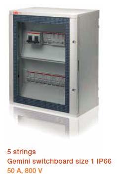


61 ABB Systems and Solutions Our offering Electrification Products Division Prod. Range 1 to 32 Strings OFFERING CATEGORIES SCHEMATIC PRODUCT RANGE DC EQUIPMENTS AC EQUIPMENTS SOLAR TRACKING January 30, 2017 Slide 62


62 ABB Systems and Solutions Our offering Electrification Products Division CMS System OFFERING CMS-System up to 64 strings PC/ PLC for processing, storage, visualisation of the measurement data CATEGORIES SCHEMATIC PRODUCT RANGE Modbus RTU DC EQUIPMENTS AC EQUIPMENTS SOLAR TRACKING Inverter System 001 System 002 Combiner box System 247 January 30, 2017 Slide 63


 50.")

 5.8/7.5/8.")
63 ABB Systems and Solutions Our offering Electrification Products Division & DM Prod. Range OFFERING CATEGORIES SCHEMATIC TRIO (OUTD) 10/12kW TRIO (OUTD) 20/ 27.6 kw PRO 33.0 TRIO (OUTD) 50.0kW PRODUCT RANGE DC EQUIPMENTS AC EQUIPMENTS SOLAR TRACKING January 30, 2017 Slide 64 UNO (OUTD) 2 / 2.5kW TRIO (OUTD) 5.8/7.5/8.5kW TRIO (OUTD) 6.0/8.0 kw TRIO (OUTD) 10/ 12 kw


 PLUS")
 PVS800")
64 ABB Systems and Solutions Our offering Electrification Products Division & DM Prod. Range OFFERING CATEGORIES ` SCHEMATIC PRODUCT RANGE DC EQUIPMENTS AC EQUIPMENTS SOLAR TRACKING PLUS PVI 110/165/220/275/330kW (TL) PLUS PVI 134/200/267/330/400kW (TL) ULTRA 700/1050/1400kW (TL) PVS to 1000 kw PVS to 2000 kw January 30, 2017 Slide 65


65 ABB Systems and Solutions Our offering Electrification Products Division Prod. Range OFFERING CATEGORIES SCHEMATIC PRODUCT RANGE DC EQUIPMENTS AC EQUIPMENTS INSUL. MONIT.G DEV. ISL-A 600, ISL-C 600 OVR T1 & T2 OVR TC ACB Emax2 EQ Meter SOLAR TRACKING MCB+RCDb S 200, S800, F200, F204 B, F202 PV-B January 30, 2017 Slide 66 MCCB TMAX CONTACTORS GRID FEEDING MONITORING RELAYS (FOR GRID COMPLIANCE) CM-UFD.MXX AF..T RANGE
66 ABB Systems and Solutions Our offering Electrification Products Division Prod. Range OFFERING CATEGORIES SCHEMATIC PRODUCT RANGE DC EQUIPMENTS AC EQUIPMENTS SOLAR TRACKING GRID FEEDING MONITORING RELAYS CM-UFD.MXX


67 January 30, 2017 Slide 68
SUPPLEMENTAL CORRECTION SHEET FOR SOLAR PHOTOVOLTAIC SYSTEMS - ELECTRICAL
 SUPPLEMENTAL CORRECTION SHEET FOR SOLAR PHOTOVOLTAIC SYSTEMS - ELECTRICAL This is intended to provide uniform application of the codes by the plan check staff and to help the public apply the codes correctly.
2016 Photovoltaic Solar System Plan Review List
 Building Division 555 Santa Clara Street Vallejo CA 94590 707.648.4374 2016 Photovoltaic Solar System Plan Review List GENERAL PROJECT INFORMATION PLAN CHECK NO DATE JOB ADDRESS CITY ZIP REVIEWED BY PHONE
This is intended to provide uniform application of the codes by the plan check staff and to help the public apply the codes correctly.
 SUPPLEMENTAL CORRECTION SHEET FOR SOLAR PHOTOVOLTAIC SYSTEMS (ELEC) This is intended to provide uniform application of the codes by the plan check staff and to help the public apply the codes correctly.
Title Goes Here and Can Run Solar Photovoltaic up to 3 lines as shown here Systems as you see
 Title Goes Here and Can Run Solar Photovoltaic up to 3 lines as shown here Systems as you see CHAPTER 2 Outline the components of a solar photovoltaic system Describe the operation of a solar photovoltaic
Station Identification. Results. PV System Specifications. Energy Specifications. Solar Radiation (kwh/m 2 /day) Energy Value ($) AC Energy (kwh)
 Energy Value ($) AC Energy (kwh)") Energy & Cost Savings The Friends Meeting of Austin 3701 Martin Luther King Blvd. Austin, TX. 78721 (20) Sharp 208 W Modules = 4.16 kw 0.77/0.94*0.945=0.774 Derate Factor Station Identification City: Austin
Energy & Cost Savings The Friends Meeting of Austin 3701 Martin Luther King Blvd. Austin, TX. 78721 (20) Sharp 208 W Modules = 4.16 kw 0.77/0.94*0.945=0.774 Derate Factor Station Identification City: Austin
Capture The Power of Photovoltaics. IEEE Power Engineering Society Meeting May 2005
 Capture The Power of Photovoltaics IEEE Power Engineering Society Meeting May 2005 Agenda Photovoltaic Basics Applications Economics Grid Interconnection and Net Metering Grid-Tied System Components Net
LIST OF PUBLISHED STANDARDS
 Report : 08-06-08 Page o : Of 8 LIST OF PUBLISHED STDRDS umber SS umber pproved mendment SBS/TC 069 SS 959-:06/RS 05-:0.0 Photovoltaic systems for use in individual homes, schools and clinics Part : 06--8
Technical Application Papers No.10 Photovoltaic plants
 Technical Application Papers No.10 Technical Application Papers Index Introduction... 4 PART I 1 Generalities on photovoltaic (PV) plants... 5 1.1 Operating principle... 5 1.2 Energy from the Sun... 5
Energy & Cost Savings The Friends Meeting of Austin 3701 Martin Luther King Blvd. Austin, TX (46) Sharp 208 W Modules = 9.
 Sharp 208 W Modules = 9.") Energy & Cost Savings The Friends Meeting of Austin 371 Martin Luther King Blvd. Austin, TX. 78721 (46) Sharp 28 W Modules = 9.568 kw Station Identification City: Austin State: TX Latitude: 3.3 N Longitude:
Energy & Cost Savings The Friends Meeting of Austin 371 Martin Luther King Blvd. Austin, TX. 78721 (46) Sharp 28 W Modules = 9.568 kw Station Identification City: Austin State: TX Latitude: 3.3 N Longitude:
PV SYSTEMS. The main components of a PV system are an array of PV panels and an inverter.
 PV SYSTEMS The main components of a PV system are an array of PV panels and an inverter. PV Panels A typical PV panel is about 1.0 x 1.6 metres in size, and composed of 60 PV cells arranged in a 6 x 10
Introduction to Solar PV. Basics
 Introduction to Solar PV Basics Solar PV Introduction 1. Solar PV Theory a) Photoelectric Effect b) What is a Solar Cell c) How do Solar Panels work d) What are solar panel basic components e) Types of
Photovoltaic Solar Plan Review
 PAIGE B. VAUGHAN, CBO Director of Building and Safety Phone (310) 605-5509 Fax Line (310) 605-5598 E-mail:lbutler@comptoncity.org Building & Safety Department Photovoltaic Solar Plan Review Plan Check
Off-grid Power for Wireless Networks. Training materials for wireless trainers
 Off-grid Power for Wireless Networks Training materials for wireless trainers Goals Provide a general view of the parts that comprise a solar photovoltaic system for telecommunication Understand the variables
Technical specifications
 KINGDOM OF SAUDI ARABIA THE SAUDI FUND FOR DEVELOPMENT ( SFD) ITB -207-7 Technical specifications Project name: Reconstruction, Furniture and Equipping of Three Schools Photovoltaic Solar System for Holly
Microinverters: an introduction May 2013
 Productive. Reliable. Smart. Safe. Martin Fornage, CTO Microinverters: an introduction May 2013 2008-2013 Enphase Energy Microinverter: what is it? Part of a PV grid-tied system Microinverter Gateway Web
ABB central inverters PVS to 2091 kva
 SOLAR INVERTERS ABB central inverters PVS980 1818 to 2091 kva 01 ABB central inverters raise reliability, efficiency and ease of installation to new levels. The inverters are aimed at system integrators
ABB - DMPC PG Solar, Nov 2016 ABB: a leading company in solar The most comprehensive value proposition
 ABB - DMPC PG Solar, Nov 2016 ABB: a leading company in solar The most comprehensive value proposition ABB in solar: most comprehensive value proposition Remote control and monitoring Global sales and
IDCOL Technical Standard for Solar Irrigation Pump (SIP) Under TR/KABITA Program
 Under TR/KABITA Program") IDCOL Technical Standard for Solar Irrigation Pump (SIP) Under TR/KABITA Program Details of approved packages Program Daily water output (Lt/day) Maximum TDH (m) 100,000 15 50,000 30 TR/KABITA 200,000
IDCOL Technical Standard for Solar Irrigation Pump (SIP) Under TR/KABITA Program Details of approved packages Program Daily water output (Lt/day) Maximum TDH (m) 100,000 15 50,000 30 TR/KABITA 200,000
ABB central inverters PVS to 1000 kw
 ABB central inverters PVS800 100 to 1000 kw ABB central inverters raise reliability, efficiency and ease of installation to new levels. The inverters are aimed at system integrators and end users who require
ABB central inverters PVS to 1000 kw
 Solar inverters ABB central inverters PVS800 100 to 1000 kw ABB central inverters raise reliability, efficiency and ease of installation to new levels. The inverters are aimed at system integrators and
ESCI 61- PV Cells Modules and Arrays April 21- Week 3 Agenda
 April 21, 2010 1 ESCI 61- PV Cells Modules and Arrays April 21- Week 3 Agenda 3:30-4:00- PV Current Events / Possible Guest Speaker 4:00-4:45- Group Research What are the different types of PV solar cells?
Green Building Technology
 Green Building Technology Renewable Energy Sources and Design/Specification Guidelines Presented by: Kurt Uhlir & Brian Kustwin Why Renewables? Reduction of SO 2 and NOX along with greenhouse gases such
DRAFT: SOUTH AFRICAN NATIONAL STANDARD
 ISBN xxx-x-xxx-xxxxx-x SANS 10142-1-2:201X Any reference to SABS xxxx is deemed to be a reference to this standard (Government Notice No. 1373 of 8 November 2002) DRAFT: SOUTH AFRICAN NATIONAL STANDARD
Intertek Level 4 RTL (ASTA Recognized Laboratory Scheme)
") Page 1 of 6 Site(s) applicable to the recognition: Central Power Research Institute Prof Sir C.V. Raman Road P.B. No. 8066 Sadashivanagar Sub-P.O. Bangalore 560 080 India Central Power Research Institute
Page 1 of 6 Site(s) applicable to the recognition: Central Power Research Institute Prof Sir C.V. Raman Road P.B. No. 8066 Sadashivanagar Sub-P.O. Bangalore 560 080 India Central Power Research Institute
INSTALLATION MANUAL MODULE TSM-PDG5/PDG5(C) TSM-PEG5/PEG5(C) TSM-PEG40 THE. UL version IEC version. TSM_UL/IEC_IM_Dec_2014_RevB - 1 -
 TSM-PEG5/PEG5(C) TSM-PEG40 THE. UL version IEC version. TSM_UL/IEC_IM_Dec_2014_RevB - 1 -") INSTALLATION MANUAL UL version IEC version THE MODULE TSM-PDG5/PDG5(C) TSM-PEG5/PEG5(C) TSM-PEG40 TSM_UL/IEC_IM_Dec_2014_RevB - 1 - Table of Contents 1. DISCLAIMER OF LIABILITY... - 3-2. SAFETY PRECAUTIONS...
INSTALLATION MANUAL UL version IEC version THE MODULE TSM-PDG5/PDG5(C) TSM-PEG5/PEG5(C) TSM-PEG40 TSM_UL/IEC_IM_Dec_2014_RevB - 1 - Table of Contents 1. DISCLAIMER OF LIABILITY... - 3-2. SAFETY PRECAUTIONS...
ABB central inverters ULTRA-750/1100/ kW to 1560kW
 Solar inverters ABB central inverters ULTRA-750/1100/1500 750kW to 1560kW * ABB s utility-scale ULTRA inverters combine high efficiency with a wide input voltage range and multiple maximum power point
Photovoltaic systems. Dr. Ervin Rácz, Ph.D. associate professor Óbuda Univesity Bécsi u. 94., Budapest H-1034 Hungary
 Photovoltaic systems Dr. Ervin Rácz, Ph.D. associate professor Óbuda Univesity Bécsi u. 94., Budapest H-1034 Hungary racz.ervin@kvk.uni-obuda.hu Green Waves 2nd Autumn University Budapest,, 21 November,
IDCOL Technical Standard for Solar Irrigation Pump (SIP) Under Ownership Model
 Under Ownership Model") IDCOL Technical Standard for Solar Irrigation Pump (SIP) Under Ownership Model Configuration of approved packages: Program Daily water output (Lt/day) 100,000 Maximum TDH (m) Minimum PV capacity (kwp)
IDCOL Technical Standard for Solar Irrigation Pump (SIP) Under Ownership Model Configuration of approved packages: Program Daily water output (Lt/day) 100,000 Maximum TDH (m) Minimum PV capacity (kwp)
ABB central inverters PVS to 2000 kva
 Solar inverters ABB central inverters 1818 to 2000 kva ABB central inverters raise reliability, efficiency and ease of installation to new levels. The inverters are aimed at system integrators and end
PRESENTATION ON HYBRID SOLAR SYSTEM BASED ON SUN SINE SMART MICRO INVERTERS
 WELCOME PRESENTATION ON HYBRID SOLAR SYSTEM BASED ON SUN SINE SMART MICRO INVERTERS SUN AS AN IMPORTANT SOURCE OF ENERGY The demand for the renewable energy sources have been increasing recently due to
INSTALLATION INSTRUCTION AND MAINTENANCE MANUAL
 INSTALLATION INSTRUCTION AND MAINTENANCE MANUAL FOR CRYSTALLINE SOLAR PV MODULE REVISIONS Risen Energy Co.,Ltd REV ECO/NPA DESCRIPTION OF CHANGE CHK D/DATE APP D/DATE TITLE: A 07-2015 Revised the entire
E-15 Uninterruptible Power Systems (UPS)
") Guideline No.E-15 (201705) E-15 Uninterruptible Power Systems (UPS) Issued date: May 9, 2017 China Classification Society Foreword This Guideline is a part of CCS Rules, which contains technical requirements,
Guideline No.E-15 (201705) E-15 Uninterruptible Power Systems (UPS) Issued date: May 9, 2017 China Classification Society Foreword This Guideline is a part of CCS Rules, which contains technical requirements,
Math and Science for Sub-Saharan Africa (MS4SSA)
") () Project-Based Learning: Introduction to Photovoltaics M.G. Zebaze Kana Visiting Scholar, Introduction to Electricity and Photovoltaics Section A: Background and introduction Section B: Introduction
() Project-Based Learning: Introduction to Photovoltaics M.G. Zebaze Kana Visiting Scholar, Introduction to Electricity and Photovoltaics Section A: Background and introduction Section B: Introduction
SMPPT. Solar Charge Controller with Maximum Power Point Tracking. Installation & Operation Manual
 SMPPT Solar Charge Controller with Maximum Power Point Tracking 10A/20A/30A 12V/24V Installation & Operation Manual 1 Dear Consumer: Thank you very much for using our product! We will offer you the permanent
PQstorI One stop solution for energy storage and power quality
 ENERGY STORAGE INVERTERS PQstorI One stop solution for energy storage and power quality s.a. ABB n.v. Power Quality Products Allée Centrale 10 Z.I. Jumet B-6040 Charleroi (Jumet) Belgium Phone: +32(0)
Regenerative Utility Simulator for Grid-Tied Inverters
 Regenerative Utility Simulator for Grid-Tied Inverters AMETEK s RS & MX Series with the SNK Option provides the solution Testing of grid-tied inverters used in solar energy systems is emerging as a major
Solar Power Switchgear & Energy Storage Renewable Energy Systems
 7 Solar Power Switchgear & Energy Storage Renewable Energy Systems - Solution Brochure www.apt-power.com 433 N. 36 th Street PROVIDING A COMPREHENSIVE Lafayette, IN 47905 www.apt-power.com 433 APPROACH
The University of New South Wales. School of Electrical Engineering and Telecommunications. Industrial and Commercial Power Systems Topic 2
 The University of New South Wales School of Electrical Engineering and Telecommunications Industrial and Commercial Power Systems Topic 2 SWITCHBOARDS Overview Also called Switchgear and Controlgear Assembly
E-15 Uninterruptible Power Systems (UPS)
") Guideline No.E-15 (201510) E-15 Uninterruptible Power Systems (UPS) Issued date:20 October, 2015 China Classification Society Foreword This Guide is a part of CCS Rules, which contains technical requirements,
Guideline No.E-15 (201510) E-15 Uninterruptible Power Systems (UPS) Issued date:20 October, 2015 China Classification Society Foreword This Guide is a part of CCS Rules, which contains technical requirements,
photovoltaic NEW Safe product solutions conforming to standards for Industrial Electrical Power Distribution Systems with extended product range
 Professional Photovoltaic Distributors NEW with extended product range 10 11 Safe product solutions conforming to standards for photovoltaic plants Industrial Electrical Power Distribution Systems Solar
Jorge Álvarez, PM Solar, Abril 15 th - Santiago. ABB Solar Central lnverters (PMGD)
") Jorge Álvarez, PM Solar, Abril 15 th - Santiago ABB Solar Central lnverters (PMGD) Index 1. Market Scenario 2. PMGD Solutions 2.1. ULTRA Inverters 2.2. ULTRA-MVC-Skid 3. Service February 15, 2011 Slide
Jorge Álvarez, PM Solar, Abril 15 th - Santiago ABB Solar Central lnverters (PMGD) Index 1. Market Scenario 2. PMGD Solutions 2.1. ULTRA Inverters 2.2. ULTRA-MVC-Skid 3. Service February 15, 2011 Slide
Ecole ECOCLIM2018 Le solaire photovoltaïque.
 Ecole ECOCLIM2018 Le solaire photovoltaïque yvan.bonnassieux@polytechnique.edu Summary q Energetic context q Solar cells: Operating principle q Comparison crystalline/amorphous silicon cells q Photovoltaic
Annex to the Accreditation Certificate D-PL according to DIN EN ISO/IEC 17025:2005
 Deutsche Akkreditierungsstelle GmbH Annex to the Accreditation Certificate D-PL-19125-01-00 according to DIN EN ISO/IEC 17025:2005 Period of validity: 2015-05-11 to 2018-12-15 Holder of certificate: Institute
CP-250E-60/72-208/240-MC4 Microinverter with Modular Trunk Cable
 CP-250E-60/72-208/240-MC4 Microinverter with Modular Trunk Cable Chilicon Power Aug 2016 1 CONTENTS CP-250E Microinverter System... 3 The CP-100 Cortex Gateway... 3 Important Safety Information... 4 Inverter
3 Phase Power Systems - Designed for Canada
 3 Phase Power Systems - Designed for Canada AC OUTPUT NESS-25kVA - Mobile NESS-50kVA - Mobile Units Rated AC Power Output 33 66 kw Maximum AC Power Output 33 66 kw AC Output Line Connection 4 - wire (L1-L2-L3-N)
GRID CONNECTED 400kWp SOLAR ROOF TOP POWER PLANT NET METERING AT KARNATAKA STATE CRICKET ASSOCIATION M. CHINNASWAMY STADIUM, BENGALURU
 MGIRED Journal Volume 2(1) : 125-128 ISSN 2393-9605 GRID CONNECTED 400kWp SOLAR ROOF TOP POWER PLANT NET METERING AT KARNATAKA STATE CRICKET ASSOCIATION M. CHINNASWAMY STADIUM, BENGALURU Punati Sridhar,
PV Fuse-Links Superior Protection of Valuable Photovoltaic Modules
 PV Fuse-Links Superior Protection of Valuable Photovoltaic Modules Fuses have been used for electric circuit protection since late 19 th century. However, new technologies like photovoltaic (PV) power
Philadelphia Solar Installation and Operation Manual
 Installation and Operation Manual IEC1703 VERSION 2018 Philadelphia Solar Installation and Operation Manual IMPORTANT SAFETY INSTRUCTIONS: This manual contains important safety instructions for the PV
3.6 Kwp Solar system Supply, Installation, Commissioning & Maintenance of Solar Systems to YEMAC office in HADDA street, Sana a city
 LOT1 3.6 Kwp Solar system Supply, Installation, Commissioning & Maintenance of Solar Systems to YEMAC office in HADDA street, Sana a city 1 LOT 1 3.6 Kwp Solar PV Power Solution with Battery Backup Table
Photovoltaic System Overcurrent Protection
 Photovoltaic System Overcurrent Protection Photovoltaic System Overcurrent Protection Introduction Solar Photovoltaic (PV) systems have, over the last fifty years, evolved into a mature, sustainable and
Distribution division. Solar Photovoltaic Catalogue. Premier Plaan. Smart solutions for the solar energy sector around the world
 Distribution division Solar Photovoltaic Catalogue Premier Plaan Smart solutions for the solar energy sector around the world IM60 Series Photovoltaic Modules Peak Power: 230-250 Wp FEATURES 60 poly-crystalline
Solar Powered System - 2
 Solar Matters III Teacher Page Solar Powered System - 2 Student Objective The student: given a photovoltaic system will be able to name the component parts and describe their function in the PV system
SOLAR PUMPING March 7 th 2013
 SOLAR PUMPING March 7 th 2013 1 SD700 SP Introduction 2 Operation modes 3 Hydraulics 4 Submersible pumps 5 SD700SP LCoW 6 SD700SP Ordering Info 7 SD700SP Sample 01 Introduction/ What is Solar Pumping?
ENGINEERING SPECIFICATION
 December 206 ENGINEERING SPECIFICATION No. of 6 DATE: 2-9-6 CATEGORY SUBJECT TABLE OF CONTENTS. Overview... 2 2. General Requirements for Service... 3 3. Definitions... 3 4. Abbreviations... 5 5. References
Introduction to Solar Cell Materials
 1 Introduction to Solar Cell Materials 22 February 2011; Ø186 P.Ravindran, FME-course on Ab initio Modelling of solar cell Materials February 2011 Introduction to Solar Cell Materials-I Photovoltaic cell:
GENERAL SPECIFICATIONS FOR THE DESIGN, SUPPLY AND INSTALLATION OF A SMALL SCALE PHOTOVOLTAIC SYSTEM (2014)
") GENERAL SPECIFICATIONS FOR THE DESIGN, SUPPLY AND INSTALLATION OF A SMALL SCALE PHOTOVOLTAIC SYSTEM (2014) A. GLOSSARY OF TERMS Solar photovoltaic components Crystalline silicon A general category of silicon
GENERAL SPECIFICATIONS FOR THE DESIGN, SUPPLY AND INSTALLATION OF A SMALL SCALE PHOTOVOLTAIC SYSTEM (2014) A. GLOSSARY OF TERMS Solar photovoltaic components Crystalline silicon A general category of silicon
INGECON SUN PowerMax B SERIES. A new generation of central photovoltaic inverters
 INGECON SUN PowerMax B SERIES A new generation of central photovoltaic inverters INGECON SUN PowerMax - B Series Main features of Ingeteam s central PV inverters The greatest power density on the market:
Solar Charge Controller
 Solar Charge Controller Solar charge controller The most basic solar charge controller simply: Monitors the battery voltage Opens the circuit Stopping the charging, when the battery voltage rises to a
Guidelines for connection of generators:
 Guidelines for connection of generators: Greater than 30 kva, and not greater than 10 MW, to the Western Power distribution network January, 2017. EDM 32419002 / DM 13529244 Page 1 of 14 Contents 1 INTRODUCTION...
10/2015 CUBICLE AND METAL-CLAD MEDIUM VOLTAGE SWITCHGEARS WEGA 07 WEGA 12 WEGA 17 WEGA 24 WEGA 36
 10/2015 CUBICLE AND METAL-CLAD MEDIUM VOLTAGE SWITCHGEARS WEGA 07 WEGA 12 WEGA 17 WEGA 24 WEGA 36 Gdańsk, October 2015 Improving the competitiveness of the company ELMOR through investments introducing
Power Conversion System The Best Technology for your photovoltaic and storage system
 The Best Technology for your photovoltaic and storage system The Best Technology for your photovoltaic and storage system EEI. Experience and Reliability since 1978 EEI s mission started in 1978 coming
Solar irradiation angle
 Solar irradiation angle By Inhoud 1. General facts about solar energy... 3 Introduction... 3 The beginning... 3 Some short insight in the history of the use of solar energy... 3 What is sunlight?... 3
Issue Title Remarks. Instrument transformers See IEC 61869
 357 Appendix Norms and Standards As far as norms and standards are mentioned in this book, the respective citation of IEC or DIN EN is given. If IEC-standards or DIN EN-norms are not available, the European
Residential Photovoltaic (PV) Packet
 Packet") Development Services Department Building Division 311 Vernon Street Roseville, California 95678-2649 (916) 774-5332 Fax (916) 774-5394 Residential Photovoltaic (PV) Packet The Roseville Municipal Code
Development Services Department Building Division 311 Vernon Street Roseville, California 95678-2649 (916) 774-5332 Fax (916) 774-5394 Residential Photovoltaic (PV) Packet The Roseville Municipal Code
Concepts and Installation of Grid Connected PV Systems NIUE, July 2009
 Small-Utility Utility-Scale PV Generation : Concepts and Installation of Grid Connected PV Systems NIUE, July 2009 Dipl.-Ing. Heinz-W. Boehnke www. TECHNOSOL. de Presentation Outline PV- Potentials PV-
Design and study of distributed photo-voltaic power generation system in sewage treatment plant
 Design and study of distributed photo-voltaic power generation system in sewage treatment plant Zhang Mingsheng 1,Wu Hesong *2,Wan Wenkui 1,Feng Peilei 3 1 Kunming University of Science and Technology
SLOVAK UNIVERSITY OF TECHNOLOGY Faculty of Material Science and Technology in Trnava ELECTRICAL ENGINEERING AND ELECTRONICS.
 SLOVAK UNIVERSITY OF TECHNOLOGY Faculty of Material Science and Technology in Trnava ELECTRICAL ENGINEERING AND ELECTRONICS Róbert Riedlmajer TRNAVA 2007 Unit 14 - Fundamentals of power system protection
SWITCHGEAR FOR SERVICE UP TO 36kV (CABLE AND OVERHEAD CONDUCTOR CONNECTED)
") PRODUCED BY THE OPERATIONS DIRECTORATE OF ENERGY NETWORKS ASSOCIATION Issue 3 2012 SWITCHGEAR FOR SERVICE UP TO 36kV (CABLE AND OVERHEAD CONDUCTOR CONNECTED) www.energynetworks.org 2012 Energy Networks
PRODUCED BY THE OPERATIONS DIRECTORATE OF ENERGY NETWORKS ASSOCIATION Issue 3 2012 SWITCHGEAR FOR SERVICE UP TO 36kV (CABLE AND OVERHEAD CONDUCTOR CONNECTED) www.energynetworks.org 2012 Energy Networks
Chapter 3 Solar PV Panel: Components Details and Fabrication
 Chapter 3 Solar PV Panel: Components Details and Fabrication Background After deciding the idea of position of Solar PV Panel, the next step is to conceptualize and fabricate one module and deploy it on
Solar Photovoltaic Power. Overarching Objectives. How many questions? 9/16/2012. From plan review to Final Inspection
 Solar Photovoltaic Power From plan review to Final Inspection Overarching Objectives A understandable and predictable process for both the Installer and the Inspector. The installation of safe, efficient,
Photovoltaic System Overcurrent Protection
 Photovoltaic System Overcurrent Protection Introduction Solar Photovoltaic (PV) systems have, over the last fifty years, evolved into a mature, sustainable and adaptive technology. This technology is improving
General Installation Manual 2007 Sanyo Electric Co., Ltd. All Rights Reserved 6/15/07
 General Installation Manual for SANYO HIT Photovoltaic Modules. Please read this manual completely before use or installation of SANYO modules. This manual applies to the following models: HIP-205BA3,
Mini-Grid PV Installations
 Mini-Grid PV Installations Dipl.-Ing. Heinz-W. BöhnkeB www.technosol.de ADB-REEP REEP-Workshop Suva, Fiji, February 2006 Presentation Outline PV-Options and Potentials PV-Mini Grid Application Objectives
- Solar PV systems and integration - GIZ - All rights reserved
 - Solar PV systems and integration - 1 Content Part 2 1. Single line diagrams of Solar PV systems 2. Integration of Solar PV components 3. Understanding batteries Realisation 4. Different Solar PV systems
CHAPTER 10 ELECTRICAL. Notes:
 CHAPTER 10 ELECTRICAL 1001.0 General Requirements. Electrical wiring and equipment shall comply with the requirements of NFPA 70, National Electrical Code (NEC), or local ordinances. 1002.0 Solar Photovoltaic
PV System Components. EE 495/695 Spring 2011
 PV System Components EE 495/695 Spring 2011 Main Components of Grid-Connected PV systems Battery storage is added to some grid-tied PV systems. Example of a grid-tied PV systems Main Components of Stand-Alone
IDCOL Technical Standard for Solar Irrigation Pump (SIP) Projects
 Projects") P a g e 1 IDCOL Technical Standard for Solar Irrigation Pump (SIP) Projects Scope of standardization: Equipment standardization : 1. Pump & Motor 2. PV panels 3. Controller Civil construction standardization:
P a g e 1 IDCOL Technical Standard for Solar Irrigation Pump (SIP) Projects Scope of standardization: Equipment standardization : 1. Pump & Motor 2. PV panels 3. Controller Civil construction standardization:
ABB circuit-breakers for direct current applications
 September 2007 1SDC007104G0201 ABB circuit-breakers for direct current applications ABB circuit-breakers for direct current applications Index 1 Introduction... 2 2 Generalities on direct current... 3
APPLICATION NOTE TESTING PV MICRO INVERTERS USING A FOUR QUADRANT CAPABLE PROGRAMMABLE AC POWER SOURCE FOR GRID SIMULATION. Abstract.
 TESTING PV MICRO INVERTERS USING A FOUR QUADRANT CAPABLE PROGRAMMABLE AC POWER SOURCE FOR GRID SIMULATION Abstract This application note describes the four quadrant mode of operation of a linear AC Power
Code Calculations. for an Off-Grid PV System
 Code Calculations for an Off-Grid PV System John Wiles Sponsored by the Photovoltaic Systems Assistance Center, Sandia National Laboratories Judy LaPointe s home is on its way to becoming a finished, off-grid
Wind Energy System.
 Wind Energy System www.theoenv.com Wind Turbine System A wind turbine is using aerodynamic effect to rotate blades and transform wind into mechanical energy, the mechanical energy then transformed into
INSTALLATION MANUAL THE / MODULE. IEC & UL version
 INSTALLATION MANUAL IEC & UL version THE / MODULE Duomax Duomax Duomax M Plus TSM-PDG40.40 TSM-PDG40.47 TSM-PDG5.40 TSM-PDG5.47 TSM-PDG14.40 TSM-PDG14.47 TSM-PEG40.40 TSM-PEG40.47 TSM-PEG5.40 TSM-PEG5.47
There s a new power in Solar 1500V ultra-high power string inverters for utility-scale PV applications
 PRODUCT MANAGEMENT, REV. NOVEMBER- 2018 There s a new power in Solar 1500V ultra-high power string inverters for utility-scale PV applications Andrea Genovesi, Gianluca Marri, Marco Trova [MW] Utility-scale
Solar inverter AX-series
 Power Supplies Inverters Solar inverter AX-series 1-5kVA Multifunctional inverter NEU / NEW PV inverter PV / Battery Charger with 3-stage charge Battery-backed power supply Sine wave inverter with charging
MASTERYS IP+ 10 to 80 kva
 MASTERYS IP+ 10 to 80 kva OBJECTIVES The aim of these specifications is to provide: the information required to choose the right uninterruptible power supply for a specific application. the information
Solar PV Standard Electrical Plan
 *** Provide this document to the inspector along with ALL system installation instructions *** Project Address: Permit Number: SCOPE: Standard plan for installation of solar PV systems utilizing 2 wire
EPUB // WHAT IS A SOLAR CELL ARCHIVE
 20 May, 2018 EPUB // WHAT IS A SOLAR CELL ARCHIVE Document Filetype: PDF 178.72 KB 0 EPUB // WHAT IS A SOLAR CELL ARCHIVE Yet manufacturing all those solar panels. The diagram above illustrates the operation
Copyright 2012 DelSolar Co. Ltd MQWRD installation manual-iec Ver. 1.4
 INSTALLATION MANUAL IEC Version www.delsolarpv.com Copyright 2012 DelSolar Co. Ltd MQWRD-01-14--installation manual-iec Ver. 1.4 Content General information 1 Safety precaution for installing solar PV
Solar Photovoltaic (PV) System Components
 System Components") az1742 August 2017 Solar Photovoltaic (PV) System Components Dr. Ed Franklin Introduction Solar photovoltaic (PV) energy systems are made up of different components. Each component has a specific role.
az1742 August 2017 Solar Photovoltaic (PV) System Components Dr. Ed Franklin Introduction Solar photovoltaic (PV) energy systems are made up of different components. Each component has a specific role.
NOTICE INVITING TENDER
 TENDER FOR SUPPLY, INSTALLATION AND COMMISSIONING OF 30kWp On Grid SOLAR POWER PLANT AT FACC/CHRD/LAKE HALL, BIDHAN CHANDRA KRISHI VISWAVIDYALAYA (BCKV), KALYAN, DIST NADIA, WEST BENGAL, INDIA, PIN 741235
ABB AG - EPDS. Ultra-Fast Earthing Switch UFES active internal arc protection
 ABB AG - EPDS Ultra-Fast Earthing Switch UFES active internal arc protection Agenda Arc fault Protection concepts Ultra-Fast Earthing Switch type UFES Principle Components Differentiation of protection
IEC INSTALLATION INSTRUCTION AND MAINTENANCE MANUAL FOR CRYSTALLINE SOLAR PV MODULE
 AND MAINTENANCE MANUAL FOR CRYSTALLINE SOLAR PV MODULE AUTHOR(S): Bypina Veerraju Chaudary, Andy Nguyen, Yang Xiaowu Page 1 of 14 1. INTRODUCTION This installation instruction manual provides information
TANZANIA BUREAU OF STANDARDS
 EDC 5 (5235) P3 Mini-Grid Systems DRAFT TANZANIA STANDARD (Draft for comments only) Part 2: Application of Inverters TANZANIA BUREAU OF STANDARDS TBS 2017 First Edition 2017 T able of content 1 2 3 4 5
Safety and Installation Instructions For Fluitecnik PV Modules
 Safety and Installation Instructions For Fluitecnik PV Modules 1.0 Introduction This manual provides safety and installation instructions for (PV) Fluitecnik Sun Energy photovoltaic (PV) modules registered
String Monitoring and Control System for Solar Photo Voltaic Power Plants
 ISSN 2278 0211 (Online) String Monitoring and Control System for Solar Photo Voltaic Power Plants K. Ajay Senior Manager, Control & Instrumentation Lab, BHEL Corporate Research & Development, Vikasnagar,
Version: GCLSI_ _V2. Photovoltaic Module Installation Manual for GCL System Integration Technology Co., Ltd.
 Version: GCLSI_2018.7.13_V2 Photovoltaic Module Installation Manual for GCL System Integration Technology Co., Ltd. CONTENTS PURPOSE OF THIS MANUAL... 2 DISCLAIMER... 2 SAFETY & TRANSPORT... 3 MECHANICAL
Yield Reduction Due to Shading:
 x9 31 x SunPower 1 x Power-One SPR-E0-37 37 W TRIO-8.5-TL-OUTD 10 ; 1x13 1x13 1 x Power-One 10 ; -30 7.5kW 9 x SunPower 1 x Power-One SPR-E0-37 37 W 10 ; 59 7.5kW 7 x SunPower 1 x Power-One SPR-E0-37 37
Components for your PV Solar Electric System
 Components for your PV Solar Electric System Here is a brief description of the major components of a Solar Electric System. The components vary depending on whether batteries will be used in your system.
MAKING MODERN LIVING POSSIBLE. UniLynx Indoor Installation Manual. ULX 1800i ULX 3000i ULX 3600i ULX 5400i SOLAR INVERTERS
 MAKING MODERN LIVING POSSIBLE UniLynx Indoor Installation Manual ULX 1800i ULX 3000i ULX 3600i ULX 5400i SOLAR INVERTERS Contents Contents 1. Introduction 2 Introduction 2 Installation Sequence 2 Important
Renewable sources of electricity a brief overview
 Micro generation 11 Renewable sources of electricity a brief overview THE SCOPE of the 17th Edition is wider and contains many new requirements, including additional requirements to ensure the safe connection