Maxi Move TM. Instructions for Use. ...with people in mind EN rev /2017
|
|
|
- Andrew Powell
- 5 years ago
- Views:
Transcription


1 Maxi Move TM Instructions for Use EN rev / with people in mind
2 Design Policy and Copyright and are trademarks belonging to the ArjoHuntleigh group of companies. ArjoHuntleigh As our policy is one of continuous improvement, we reserve the right to modify designs without prior notice.the content of this publication may not be copied either whole or in part without the consent of ArjoHuntleigh.
3 Contents General Information... 5 Definitions Used in this Manual... 5 Manufacturer Information... 5 Intended Use... 5 Conditions... 6 Operational Life... 6 Policy on Number of Staff Members Required for Patient Transfer... 6 Safety Instructions... 7 Symbols Used... 7 Homecare Environment Considerations... 8 Product Description/Functions... 9 Parts Referred to in this Manual... 9 Slings Controls and Features Control Handset Control Panel Stop Button (red) Power Button (green) System Failure Wind Down Facility Automatic Cut-Out Anti-Crush System Battery Indicator Sleep Mode Usage Counter Adjustable Width Chassis Legs Chassis Castor Brakes Jib and Spreader Bars/Stretcher Frame Using your MAXI MOVE Before Approaching the Patient Powered Opening V Chassis MAXI MOVE Lock and Load System Testing the Attachment Using the DPS Spreader Bar To Lift from a Chair To Lift from the Bed To Lift from the Floor Powered DPS Spreader Bar Care of Your Powered DPS Spreader Bar Using the Loop Spreader Bar To Lift from a Chair To Lift from the Bed To lift from the Floor Using the Stretcher Frame Using the Soft Stretcher Using the Strap Stretcher Scale Patient Scale Information Descriptive Marking/Seals C.E. Units only Reinspection Display Symbols/Functions Overload Warning Symbol Method A - Weighing Before the Patient is Suspended in the Sling Method B - Weighing with the Patient Already Suspended in the Sling Units of Measure Scale - Handset Instructions Mini-Guide Battery Charging
4 Contents Battery Pack Removing the Battery Pack Charging your Battery Battery and Battery Charger Safety Practices Care of your MAXI MOVE Sling Cleaning and Care Lift Cleaning and Care Mandatory Daily Checks Periodic Testing Servicing Advice Troubleshooting Labels Technical Specifications Lift Dimensions Appendix - Scale Gravity Code Configurations Viewing the Gravity Code Configuration European Gravity Zones Map Gravity Adjustment Table Electromagnetic Compatibility Electromagnetic Compliance Electromagnetic Emissions Electromagnetic Immunity
5 General Information Thank you for buying an ArjoHuntleigh product. Your MAXI MOVE is part of a series of quality products designed especially for hospitals, nursing homes and other health care uses. We are dedicated to serving your needs and providing the best products available along with training that will bring your staff maximum benefit from every ArjoHuntleigh product. Contact us if you need more information, want to report an unexpected event or need any help in setting up, using or maintaining your your ArjoHuntleigh product. All references to the patient in these instructions refer to the person being lifted, and references to the attendant refer to the person who operates the MAXI MOVE. Techniques described in these instructions for fitting slings and lifting patients from a reclining position can be used for patients regardless of where they may be lying; on the bed or on the floor. Similarly, lifting a patient from a chair employs the same techniques as when lifting a patient from a wheelchair or from a sitting position on the edge of a bed. NOTE: The need for a second attendant to support the patient must be assessed in each individual case. These instructions specifically show both the clip attachment slings being used with the standard Dynamic Positioning System (DPS) and the loop attachment slings for loop spreader bars. The same methods and techniques described for the standard DPS can also be applied to the optional, powered DPS. Definitions Used in this Manual WARNING: Means: Failure to understand and follow these instructions may result in injury to yourself and others. CAUTION: Manufacturer Information ArjoHuntleigh AB Hans Michelsensgatan Malmö SWEDEN Intended Use WARNING: To avoid injuries that can be attributed to the use of inadequate parts, ArjoHuntleigh strongly advises and warns that only ArjoHuntleigh designated parts should be used on equipment and other appliances supplied by ArjoHuntleigh. Unauthorized modifications on any ArjoHuntleigh equipment may affect its safety. ArjoHuntleigh will not be held responsible for any accidents, incidents or lack of performance that occur as a result of any unauthorized modification to its products. MAXI MOVE is a mobile, passive lift with removable spreader bar. MAXI MOVE is intended to be used under professionnal staff supervision in hospitals, nursing homes or other health care facilities where the patient: sits in a wheelchair has no capacity to support himself/herself cannot stand unsupported and is not able to bear weight; not even partially is dependent on the caregiver in most situations Or where the patient: is passive might be almost or completely bedridden is often stiff or has contracted joints is totally dependent on the caregiver MAXI MOVE must always be handled by a trained caregiver and in accordance with the instructions outlined in this manual. MAXI MOVE is intended to be used with ArjoHuntleigh slings. Only use slings and stretchers supplied by ArjoHuntleigh that are designed to be used with your MAXI MOVE. MAXI MOVE equipped with optionnal extra low height caster is not intended to be used on carpet. Means: Failure to follow these instructions may cause damage to the product(s). NOTE: Means: This is important information regarding the correct use of the equipment. 5
6 General Information Conditions The unit is cared for and serviced in accordance with recommended, published Instruction for Use and the Preventive Maintenance Schedule. The unit is maintained to the minimum requirements as published in the Preventive Maintenance Schedule. The servicing and product care, in accordance with ArjoHuntleigh requirements, must begin on first use of the unit by the customer. The equipment must be used for its intended purpose only and is operated within the published limitations. Only ArjoHuntleigh designated spare parts should be used. Operational Life The expected operational life of your ArjoHuntleigh lift is ten years from the date of manufacture, providing the following conditions are adhered to: The expected operational life for fabric slings and fabric stretchers is approximately two years from date of purchase. This life expectancy only applies if the slings and stretchers have been cleaned, maintained and inspected in accordance with the ArjoHuntleigh Sling Information documents, the Instruction For Use and the Preventive Maintenance Schedule. The expected life for other consumable products, such as batteries, fuses, lamps, gel cushions, filters, seal kits, seat inserts, mattresses, safety belts, padded covers, straps and cords is dependent upon the care and usage of the equipment concerned. Consumables must be maintained in accordance with published Instruction for Use and the Preventive Maintenance Schedule. Policy on Number of Staff Members Required for Patient Transfer ArjoHuntleigh s passive and active series of lifts are designed for safe usage with one caregiver. There are circumstances, such as combativness, obesity, contracture etc. of the individual that may dictate the need for a two-person transfer. It is the responsibility of each facility or medical professional to determine if a one or two person transfer is more appropriate, based on the task, resident load, environment, capability, and skill level of the staff members. 6
7 Safety Instructions Symbols Used General Key to symbol This symbol is accompanied by a date (to indicate the date of manufacture) and by the address of the manufacturer. This symbol indicates that the products comply with medical device directive 93/42/EEC This symbol indicates that the products comply with medical device directive 93/42/EEC, and that the Technical File has been reviewed by BSI, accredited notified body in Europe. This symbol indicates that the products comply with medical device directive 93/42/EEC, and that the the scale was initially calibrated under the authorization of the NATIONAL MEASUREMENT OFFICE, accredited notified body in Europe This symbol is accompanied by the manufacturer's catalogue number. This symbol is accompanied by the manufacturer's serial number. This symbol indicates separate collection for all batteries and accumulators as per the WEEE Directive. These symbols refer to the Instructions for Use. This symbol indicates a type BF applied part. This symbol indicates a risk of pinching. This symbol represents a weight scale. This symbol indicates that the scale is a non-automatic instrument; accuracy class 3. SWL Safe Working Load represents the maximum load the lifter is rated for safe operation. Maximum total mass of equipment including its safe working load. + = kg / lb SWL Battery Charger Related Key to symbol This symbol indicates a class II electrical equipment: term referring to electrical equipment in which protection against electric shock does not rely on basic insulation only. Fig. 1 7
8 Safety Instructions Before using your MAXI MOVE, familiarize yourself with the various parts and controls as shown in Fig. 3, and other illustrations. Then, read this manual thoroughly in its entirety before using your MAXI MOVE. Information in the manual is crucial to the proper operation and maintenance of the equipment, and will help protect your product and ensure that the equipment performs to your satisfaction. Some of the information in this booklet is important for your safety and must be read and understood to help prevent possible injury. If there is anything in the manual that you find is confusing or difficult to understand, please contact your local ArjoHuntleigh agent (the telephone number appears on the last page of this manual). LEFT RIGHT References to left or right in these instructions are as viewed from the caregiver s pushing position, standing at the rear of the MAXI MOVE and facing forward. Fig. 2 This product has been designed and manufactured to provide you with trouble-free use. However, this product does contain components that are subject to wear with regular use. CAUTION: Some of these parts are critical to ensure the safe operation of the lift. They will need examining and servicing on a regular basis and must be replaced as needed. See also Care of your MAXI MOVE section. CAUTION: Use only ArjoHuntleigh slings and stretchers that have been specifically designed for the MAXI MOVE. WARNING: Before using the MAXI MOVE, a clinical assessment of the patient s suitability for transfer must be carried out by a qualified health professional considering that, among other things, the transfer may induce substantial pressure on the patient s body. A transfer conducted when it should not can degrade the patient s health condition. WARNING: Patients with spasms can be lifted, but great care should be taken to support the patient s legs to prevent fall risk and injuries. WARNING: Do not overload the MAXI MOVE beyond the approved lifting capacity of the lowest rated attachment/accessory in order to avoid patient injury. If the maximum load differs between floor lift, spreader bar and body support unit (i.e. sling), then the lowest maximum load shall always be used. Take care when manually lifting alternative/ optional components such as stretcher frames, spreader bars etc., in order to avoid injury. Do not attempt to manually lift the complete lift. CAUTION: Although manufactured to a high standard, the MAXI MOVE and accessories should not be left in humid or wet areas. Do not, under any circumstances, spray the MAXI MOVE or accessories (excluding slings or ArjoHuntleigh approved wet environment equipment) with water such as under the shower. WARNING: Before lifting a patient it is advisable to familiarize yourself with and understand the operation of the various controls and features of the MAXI MOVE, and to carry out any action concerning inspection procedures. The MAXI MOVE can be supplied with a variety of optional attachments, which are not all described in these instructions. If your MAXI MOVE has been equipped with an alternative/optional sub-assembly such as stretchers, etc., always refer to the separate, relevant operating instructions supplement, as well as these instructions, before you operate the lift. This product is intended to be operated entirely by an attendant. The patient should not perform any function relating to the control of this product. A second attendant may be required with certain patients. Homecare Environment Considerations WARNING: The MAXI MOVE is not intended to be operated by children. Serious injuries could occur. NOTE: Rigorous cleaning action should be done when the MAXI MOVE is exposed to an animal. Pet hair trapped inside the device can reduce the product performance. WARNING: This product contains small parts that might present a severe danger to children if swallowed or inhaled. 8
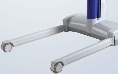
9 Product Description/Functions Parts Referred to in this Manual Fig. 3 1) Mast 2) Mast top cover 3) Maneuvering handle 4) Lift battery pack 5) Braked casters 6) Adjustable chassis legs 7) Medium DPS spreader bar (if included) 8) Lock and Load spreader bar carrier system 9) Jib 10) Control panel 11) Control handset 12)Stop 13) Power 14)Battery release 15)Battery charger 16)Two-point loop spreader bar (if included) 17) Loop medium Combi (if included) 18)Four-point loop spreader bar (if included) 19)Small DPS spreader bar (if included) 20) Medium powered DPS spreader bar (if included) 21) Large powered DPS spreader bar (if included) 22) Stretcher frame (if included) 9
10 Product Description/Functions Fig. 4 10
11 Product Description/Functions Slings The standard range of MAXI MOVE slings will support 227 kg (500 lb), the pediatric spreader bar range will support 125 kg (275 lb). All slings are size-coded with different colored edge binding or attachment strap coloring: Pediatric rated: Teal or Grey - Extra Extra Small - XXS Brown or White - Extra Small - XS Red - Small - S Standard Range: Yellow - Medium - M Green -Large - L Purple - Large Large - LL Blue - Extra Large - XL Terracotta - Extra Extra Large - XXL Always refer to the label on the sling being used to make sure of its actual safe working load (SWL). A label is placed on the spreader bar for a quick color-to-size reference (see the section entitled Labels ). A range of special purpose slings is available as accessories. For these or for special size slings, contact your ArjoHuntleigh representative. For more information on sling compatibility, use and installation, refer to Slings operating and Product Care Instructions (MAX81785M-INT). WARNING: Only use ArjoHuntleigh supplied slings and stretchers that are designed to be used with MAXI MOVE to prevent fall risk and injuries. The sling profiles illustrated (see Fig. 5) will help to identify the various ArjoHuntleigh slings and fabric stretchers available. If ArjoHuntleigh Flites (disposable slings) are to be used with your MAXI MOVE, always refer to the separate operating instructions for ArjoHuntleigh Flites (see respective sling IFU), as well as these instructions, before using. WARNING: ArjoHuntleigh slings with head supports have two pockets located in the head section. These should contain plastic reinforcement inserts during use to avoid injuries. Always ensure that these reinforcement inserts have been placed inside the sling pockets before using the sling. WARNING: ArjoHuntleigh warns of possible strangulation risks related to the use of slings. Necessary precautions should be taken to prevent these. 11
12 Product Description/Functions ArjoHuntleigh standard sling profiles that can be used with the MAXI MOVE Four-point padded sling Four-point toileting sling Four-point amputee sling Soft stretcher Strap stretcher NOTE: Other sling models are available. Contact your ArjoHuntleigh agent for more information. Scoop stretcher Fig. 5 12
13 Product Description/Functions Controls and Features Control Handset (See Fig. 6) To raise and lower the jib, open and close the chassis legs, or to operate a powered DPS spreader bar, press the appropriate on the control handset. Icons with direction arrows are printed on each for quick reference. Handset Display DPS Recline Jib Down Chassis Legs Closed Jib Up DPS Sit Up Chassis Legs Open Fig. 6 If is released during any function, powered motion will cease immediately. When not in use, the handset can be conveniently stored for later use by hooking it over the manoeuvring handle at the rear of the mast. Control Panel (See Fig. 7) An additional feature available on the MAXI MOVE, is a mast-mounted control panel, which operates in parallel with the control handset, enabling powered operations to be controlled from the lift mast as well as remotely by using the handset. As with the handset, icons with direction arrows are printed on each for quick reference. DPS Recline Jib Down Chassis Legs Closed Jib Up DPS Sit Up Chassis Legs Open Fig. 7 Stop Button (red) (See Fig. 8) In an emergency, if you have to immediately stop any powered movement (other than by releasing a control handset or control panel ), press the stop located on the control panel. Once the stop has been used, the green power will have to be pressed before the equipment can be operated again. To do this, simply push in the. Stop Power Fig. 8 Power Button (green) (See Fig. 8) Located adjacent to the stop, this is used to turn the unit on. 13
14 Product Description/Functions System Failure Wind Down Facility If electrical power fails completely due to battery power loss or other electrical malfunction, the jib can be lowered by first raising the red colored emergency lowering lever found on the rear section of the mast (See Fig. 9). Fig. 9 Next, remove the exposed locking pin from its location beneath the red colored emergency lowering lever (see Fig. 10). Fig. 10 Finally, using the lever as a crank, turn it in a clockwise rotation (see Fig. 11). One full clockwise rotation of the shaft lowers the mast jib by 10 mm (3/8 in). Fig. 11 WARNING: In order to prevent a fall risk and injuries, if the mast is in a high position and the wind-down function is used, ensure that suitable and safe measures are taken to gain access to the top cover. If the wind down function must be used, immediately remove the lift from use and contact the ArjoHuntleigh Service Department or its appointed distributor. Automatic Cut-Out This is not an operator control but a function built into the lift s electronics. If the lift is inadvertently overloaded by trying to raise or lower a load heavier than permitted, an automatic cut-out function operates to prevent the lift from raising a weight in excess of the safe working load (SWL). This will stop the lift s motion automatically. If this occurs, release the jib up on the handset or the control panel. Do not insist to raise the load. Make sure that the MAXI MOVE operates only within its safe working load. Anti-Crush System This is not an operator control but a function built into the lift s electronics. Great care should be taken not to lower the spreader bar, or stretcher onto the patient or any other obstruction. If this should happen, the unit s anti-crush system will engage, stop the motor and all downward movement will cease. If this occurs, release the jib down immediately and press the jib up to raise the jib until the lift is clear. Then remove the obstruction. Battery Indicator The battery indicator for the MAXI MOVE is a feature found on the control handset. Please refer to the Battery Charging section for operating procedures. Sleep Mode The MAXI MOVE is equipped with a powersaving feature which places the machine in sleep mode when not used for a short time. The unit is put into sleep mode in two stages: 1) After two minutes of inactivity (where no s are pressed on either the control handset or control panel), the handset s display will go into sleep mode. The display can be taken out of sleep mode by pressing any on the handset or the control panel. There will be a three second delay after which the unit is fully ready for use. 2) After six minutes of inactivity, the entire unit will placed into sleep mode and will restart only when a is pressed either on the control handset or control panel. There will be a three second delay after which the unit is fully ready for use. 14
15 Product Description/Functions Usage Counter The usage counter is a feature found on the control handset which shows the accumulated amount of time (in hours) that the lift s mast has been raised or lowered. Initially, the display will show 0.0 at the very top of the screen (right above the larger digits for the scale), indicating 0 hours of use. The measurement will increase in increments of 0.1 whenever an additional six minutes have been accumulated. Note that the counter is recording only during the movement of the mast. Keeping the unit turned on, using the powered DPS or adjusting the width of the legs will not affect the usage counter. The maintenance symbol serves as a reminder of the annual maintenance requirements for the product. It will appear on the handset display when the usage counter reaches 175 hours. This target represents the average time a lift will be used during one year. However, based on the use of the unit, the maintenance symbol can appear sooner or later than a year. When the maintenance symbol appears, the unit will still be safe to use, but the annual maintenance should be performed as soon as it is reasonably possible. The technician must reset the display to 0.0 when the annual inspection is performed to allow monitoring when the following inspection is due. Adjustable Width Chassis Legs (See Fig. 12) To open the chassis legs, press the legs open on either the control handset or control panel. When the is released, movement will stop and the chassis legs will remain securely in position. Always transfer patients with the chassis legs in the closed position. Chassis Castor Brakes (See Fig. 13) The chassis rear castors have brakes which can be foot operated to keep the MAXI MOVE in position. Lock brake Unlock brake Fig. 13 Jib and Spreader Bars/Stretcher Frame (Consult Fig. 3) Your MAXI MOVE is equipped with a quick connection device that allows you to use multiple attachments, such as loop/dps spreader bars, stretcher frames, etc. See the section entitled Using your MAXI MOVE for full instructions on installing or changing attachments. Fig
16 Using your MAXI MOVE Before Approaching the Patient Ensure that the battery pack supplied is fully charged before use (for recharging batteries, see the instructions in the Battery Charging section). When the battery pack is fully charged, remove it from the charger unit and insert it back into the MAXI MOVE. First, match the recess across the bottom of the battery pack with the protrusion at the bottom of the battery slot, then pivot the battery into position until the retaining catch engages. An electrical connection will be made automatically. Ensure that the green power (located below the control panel) is pushed in (see Fig. 8). Ensure that a selection of sling types and sizes is available for all transfers likely to be performed using the MAXI MOVE. The attendants should always tell the patient what they are going to do, and have the correct size sling ready. Whenever possible, always approach the patient from the front. NOTE: To ensure the patient s maximum comfort, do not allow the patient to hold on to the spreader bar or the jib. To remove the attachment: Hold it carefully and depress the locking clip thumb pads to release it from the T-bar (see Fig. 15A). Then, still pressing on the locking clip, lift the attachment up wards and away from the T-bar (see Fig. 15B and Fig. 15C), and store it carefully for future use. To install an attachment: Select the attachment required and while carefully handling it, with the locking clip thumb pads facing you allow the recess in the attachment to fit around the T-bar shaft (see Fig. 15D). Ensure the attachment drops down over the T-bar and that the locking clip engages fully. (see Fig. 15). A B Attachment T-bar Locking clip WARNING: Before raising the mast make sure there is enough clearance above the MAXI MOVE to ensure the safety of the patient and the people around, and to avoid injuries. Be very careful when lifting next to a door frame. WARNING: During displacement, always make sure there is enough clearance above the MAXI MOVE to ensure the safety of the patient and the people around, and to avoid injuries. Be very careful when passing through door openings. If required, the chassis legs may be opened to go around a chair or wheelchair. Powered Opening V Chassis Push the legs open on the control handset or control panel until the required width for the chassis legs is reached. To close, press the legs closed. Movement will stop if the is released, whether opening or closing. When opening or closing the legs on a powered chassis, care must be taken not to allow anything to stand in the way of the chassis moving legs. For example, pay special attention when the legs are operated around chairs or in doorways. The lift must be moved only when the chassis legs are in the closed position. MAXI MOVE Lock and Load System (See Fig. 14) If you need to install or change the attachment, such as the spreader bar or stretcher frame, proceed as follows: 16 C D Fig. 14 WARNING: Be prepared to take the full weight of the attachment when removing it from the jib to prevent a back injury. For larger attachments, or if there is any doubt about being able to lift and hold the attachment securely, use more than one person for the procedure, or support the attachment on a bed or chair.
17 Using your MAXI MOVE CORRECT CORRECT Markings on the attachment are aligned. INCORRECT WARNING: Always check that the attachment is locked in place by: 1) verifying the markings on the attachment that show that there is a proper alignment, and 2) verifying that the locking clip is fully engaged, thus ensuring that the attachment is securely fastened. An unsecured spreader bar may lead to a patient fall. Locking clip is fully engaged; the attachment is fastened securely. INCORRECT Locking clip is NOT engaged; the attachment is not fastened securely. Markings on the attachment are misaligned. Fig. 15 WARNING: DO NOT lower the attachment onto rigid surfaces (e.g. bed, floor, wheelchair armrests, etc.), to avoid the possibility of the attachment becoming dislodged from the T-bar. A dislodged attachment may later detach completely from the unit, causing the patient to fall. Testing the Attachment To ensure that the attachment is safely connected and secured to the T-bar, hold the attachment firmly with both hands, without pushing on the locking clip thumb pads, and lift the attachment upwards firmly (see Fig. 16). If the attachment becomes dislodged from the T-bar, DO NOT use the MAXI MOVE. Contact your local ArjoHuntleigh agent. Fig. 16 WARNING: Always check that the attachment is locked in place by: 1) verifying the markings on the attachment that show that there is a proper alignment, and 2) verifying that the locking clip is fully engaged, thus ensuring that the attachment is securely fastened. 17
18 Using your MAXI MOVE Using the DPS Spreader Bar To Lift from a Chair Place the sling around the patient so that the base of his/her spine is covered and the head support portion of the sling is behind the head. Pull each leg strap from under the thigh so that it emerges on the inside of the thigh (see Fig. 17). Fig. 19 Fig. 17 Ensure the positioning handle on the spreader bar is facing away from the patient, and that the open part of the spreader bar is at or just below shoulder level (see Fig. 18). CAUTION: The chassis rear castors have brakes which can be foot-operated when required (see Fig. 13). Do not apply the chassis brakes at this stage, as the position of the patient will adjust to the center of gravity of the lift while the patient is being raised. Press down on the positioning handle on the spreader bar and attach the leg strap attachment clips (see Fig. 20). Fig. 18 Ensure that the MAXI MOVE is close enough to be able to attach the sling s shoulder clips to the spreader bar. To accomplish this you may have to put the patient s feet on, or over, the chassis. WARNING: When installing and lifting using the sling with the DPS spreader bar, ensure that the patient s hands and arms are kept inside the sling at all times to prevent injuries. Do not allow the patient to hold on to the spreader bar. Once the MAXI MOVE is in position, attach the shoulder strap attachment clips to the sling attachment lugs on the spreader bar (see Fig. 19). Fig. 20 For most residents, the straight attachment of the leg clips is recommended use (see Fig. 21 ). Apply the leg clips of the sling onto the lugs so that they become positioned vertically. Fig
19 Using your MAXI MOVE If the resident is prone to kicking off the leg clip, the crossed attachment of the leg clips shall be applied, which will prohibit the clip from being kicked off (see Fig. 22). Cross the leg pieces of the sling when attaching them to the lugs. Move the lift away from the chair. The angle of recline can be adjusted to increase comfort for more restless patients. The lift can now be directed towards the following transfer point (see Fig. 24). WARNING: Do not attempt to move the lift by pulling or pushing on the mast, the jib, the spreader bar or the patient as this can cause the lift to topple over, and cause injuries. Always use the manoeuvring handle when displacing the lift. Fig. 22 If necessary, lower the spreader bar using the handset control, being careful not to lower it onto the patient. If this should happen inadvertently, there is a built-in cut-out device which will prevent any further downward movement. Do not continue to push the handset jib down. If the handset is released during the lifting or lowering procedure, powered motion will stop immediately. When lifting from a chair, some attendants prefer to connect the leg straps first. This applies in particular to patients with large thighs. In that case, press down on the position handle on the spreader bar and attach leg strap attachment clips. Then tilt the spreader bar towards the shoulders to connect the shoulder attachment clips. CAUTION: Always check that all the sling attachment clips are fully in position before and during the lifting cycle, and in tension as the patient s weight is gradually taken up. Before transferring, position the patient to face the attendant at approximately the height of a normal chair. This provides a measure of confidence and dignity to the patient. Remember to release the brakes if they have been applied, before transferring the patient. Lift the patient using the handset control, and adjust to a comfortable position for transfer (see Fig. 23). The specially designed sling, together with its integral head support, enables one person to carry out the complete lifting function without additional help. WARNING: When lowering the spreader bar, ensure that the patient s and attendant s legs and feet are well clear of any parts of the lift in order to avoid patient injuries and/or damage to the Maxi Move. Only detach the sling leg connection clips followed by the shoulder connection clips when the patient s body weight is fully supported by the bed. Fig. 24 When lowering the patient back down, lower the positioning handle to put the patient into a sitting position. This avoids further lifting strain. Take care not to push down too quickly, as this may jerk the patient s head forward. To Lift from the Bed Before lifting a person from a bed, ensure there is sufficient clearance underneath the bed to accommodate the MAXI MOVE chassis legs. Position the patient onto the sling by rolling the patient towards you, then folding the sling in half and placing it behind the patient s back (see Fig. 25). Fig. 23 Fig
20 Using your MAXI MOVE Position the sling carefully so that, when rolled back, the patient will lie on the center of the sling (see Fig. 26). Check that the head support area of the sling covers the patient s neck.. Fig. 26 When rolling the patient back onto the sling, roll the patient slightly in the opposite direction so that the folded part of the sling can be pulled forward. Alternatively, the patient can be brought into a sitting posture. Then position the sling as detailed in the section entitled To Lift From A Chair. Approach the bed with the open side of the spreader bar towards the patient s head (see Fig. 27). Fig. 28 Press down on the positioning handle until the sling leg sections can be connected (see Fig. 29). Connect the leg sections under the thighs by lifting one leg at a time. You may need to lower the spreader bar a little, using the handset control. Fig. 27 Using the adjustable width chassis, it is possible to make adjustments to the chassis leg width to assist with manoeuvrability around obstructions, such as bed legs or castors. Now position the MAXI MOVE so that the spreader bar is just above and centered over the patient. WARNING: Take care not to lower the spreader bar onto the patient to avoid injuries. Using the positioning handle, tilt the spreader bar until the shoulder attachment points can be connected to the sling shoulder strap attachment clips (see Fig. 28) Fig. 29 When lifting from the bed, some attendants prefer to connect the leg straps first. This applies in particular to patients with large thighs. In that case, raise the hip and knee into maximum flexion, and attach the leg strap attachment clips. Then tilt the spreader bar towards the shoulders to connect the shoulder attachment clips. CAUTION: Always check that all the sling attachment clips are fully in position before and during the lifting cycle, and in tension as the patient s weight is gradually taken up. Lift the patient using the handset control, and with the positioning handle, bring the patient into a comfortable position for transfer (see Fig. 30). The specially designed sling, together with its integral head support, enables one person to carry out the complete lifting function without additional help. 20
21 Using your MAXI MOVE When connecting the sling to the spreader bar, the patient s head and shoulders could be raised with pillows for additional comfort. With the open part of the spreader bar pointing down towards the shoulders, attach the shoulder strap attachment clips, as shown in Fig. 32 and inset. Fig. 30 If returning the patient to a bed, move into the desired position above the bed, adjusting the spreader bar position as necessary. Then lower the patient using the handset control When lowering the spreader bar, ensure that the patient s and attendant s legs and feet are well clear of any parts of the lift to avoid injuries. WARNING: Only detach the sling leg connection clips followed by the shoulder connection clips when the patient s body weight is fully supported by the bed to avoid any risk of fall. Pull the MAXI MOVE away before removing the sling from under the patient. If transferring the patient to a chair, refer to the section entitled To Lift from a Chair. To Lift from the Floor Fig. 32 Once connected, raise the hip and knee into maximum flexion, and push down on the positioning handle to be able to connect the leg strap attachment clips as shown in Fig. 33. This will have the effect of raising the patient s head and shoulders slightly. Put the sling around the patient, by rolling or sitting the patient up. Open the chassis legs first, then approach and lift the patient s legs over the chassis as shown in Fig. 31. CAUTION: Make sure that no strap is passing under the MAXI MOVE legs. Fig. 33 CAUTION: Always check that all the sling attachment clips are fully in position before and during the lifting cycle, and in tension as the patient s weight is gradually taken up. Fig. 31 CAUTION: While the patient is positioned over the legs as shown in Fig. 31, DO NOT operate the adjustable chassis leg controls. When lifting from the floor, some attendants prefer to connect the leg straps first. This applies in particular to very large patients with large thighs. In that case, raise the hip and knee into maximum flexion, and attach the leg strap attachment clips. Then tilt the spreader bar towards the shoulders to connect the shoulder attachment clips. When all the straps are securely attached, lift the patient from the floor in a semi-reclining position. Supporting the head can add comfort and can reassure the patient. Once raised from the floor, ensure the patient s legs are clear of the chassis before continuing to lift (see Fig. 34). 21
22 Using your MAXI MOVE The leg portions of the sling will tend to be fairly high in the patient s crotch area. Straighten them out for added comfort. The patient may then be positioned in a chair, or placed on a bed. Patients with extensor spasms may be lifted by the MAXI MOVE, but care should be taken to support the patient s legs during the beginning of the lift. WARNING: When lowering the spreader bar, ensure that the patient s and attendant s legs and feet are well clear of any parts of the lift to avoid injuries. Only detach the sling leg connection clips followed by the shoulder connection clips when the patient s body weight is fully supported by the bed. WARNING: Before using your lift equipped with the powered DPS spreader bar, familiarize yourself with the various parts as illustrated in Fig. 35. Read and thoroughly understand these operating instructions in order to avoid mistakes that could result in injury. The powered DPS spreader bar must be used in accordance with the following instructions and in conjunction with the operating instructions previously described for the manual DPS spreader bar. The lifting capacity of the lift, when equipped with the powered DPS spreader bar remains the same as the manual DPS spreader Bar. DPS actuator Sling attachment lugs Positioning handle Wet Environment Unit label Fig. 34 When lifting patients with leg amputations, use the double amputee sling (available as an accessory from ArjoHuntleigh). This sling is specially designed to accommodate each patient s center of gravity. The transferring of patients should always be done with the chassis legs closed. Manoeuvrability will be easier, especially through doorways. As usual, the patient should be positioned facing the attendant. Powered DPS Spreader Bar If your lift has been supplied equipped with a powered DPS spreader bar (see Fig. 35), the use of this type of spreader bar including sling positioning with patient, sling connection to the spreader bar, and patient handling is the same as the manual DPS spreader bar described previously in these instructions. Fig. 35 The fundamental difference is that the powered DPS spreader bar has the added advantage of enabling the patient positioning manoeuvre to be performed with minimal physical effort by the attendant. The rotation of the powered DPS spreader bar is manual and is the same as the manual DPS spreader bar. The powered DPS is classified by ArjoHuntleigh as a wet environment unit. A blue and white circular label is attached to show this. This label signifies that anything above its position must not be soaked in water, either when bathing or showering the patient. To operate the powered patient positioning function, ensure that the green power is pushed in (see Fig. 8). When ready to perform the patient positioning function (as described previously), operate the powered DPS control s on the handset (see Fig. 6) or the s found on the control panel to cause the spreader bar to move in the required position. 22
23 Using your MAXI MOVE Handset display DPS Recline Jib Down Chassis Leg Closed Jib Up DPS Sit Up Chassis Legs Open Fig. 37 Fig. 36 To stop any powered movement, release the control or press the stop. The spreader bar will remain firmly in position, once powered movement has stopped. Always ensure the spreader bar is securely connected to the jib before starting to lift. CAUTION: Before and during operation of the powered DPS spreader bar, ensure all obstructions are clear of the spreader bar, support frame and jib. Care of Your Powered DPS Spreader Bar For general care, refer to the section entitled Care of your MAXI MOVE. Refer in particular to the paragraphs on cleaning plastic parts, labels, etc. CAUTION: The DPS actuator contains moving parts. Take care not to damage it. Should the covers become damaged, do not use the lift and replace the actuator before reusing the lift. Retaining hook Sling attachment loop Two-point spreader bar Fig. 38 Use ArjoHuntleigh loop slings with the loop spreader bar (consult Fig. 4). They are available in four color-coded sizes (small, medium, large and extra-large). For details on a more specialized range of slings, please contact ArjoHuntleigh or its authorized distributors. The loop slings are available with or without a head support. A mesh sling is also available in all four sizes, with or without a head support. Using the Loop Spreader Bar If your MAXI MOVE has a loop spreader bar, ensure that the spreader bar is rotated into position before attaching the sling, so the eventual lift will resemble Fig. 37. When attaching a loop sling to the loop spreader bar, always ensure that the sling attachment loops are installed correctly into the retaining hooks (see Fig. 38). 23
24 Using your MAXI MOVE To Lift from a Chair First, ease the patient forward if necessary. Slide the sling down the patient s back until seam C reaches the base of the spine (see Fig. 39). METHOD 2 A A C B B Fig. 39 Fig. 41 Method 2 - As in Method 1, but pass each leg section of the sling under both thighs and then out the other side before attaching points B to the hooks on the opposing side of the spreader bar (see Fig. 41 above). METHOD 1 METHOD 3 Fig. 40 Method 1 - Bring attachment loops B and the leg sections of the sling underneath the patient s thighs. Ensure that the leg sections of the sling are not twisted underneath the patient. Hook the attachment loops onto the hooks on the opposing side of the spreader bar (see Fig. 40 above). Fig. 42 Method 3 - As in Method 1, but loop a leg portion of the sling under each thigh and attach to the same side hook as the shoulder attachment (left straps to left hook and right straps to right hook). This method holds the legs in abduction and is useful for toileting (see Fig. 42 above). WARNING: To prevent a fall risk, always check that all the sling attachment loops are fully in position before and during the lifting cycle, and in tension as the patient s weight is gradually taken up. When lowering, ensure that both the patient s and attendant s legs and feet are well clear of the moving mast to avoid injuries. 24
25 Using your MAXI MOVE Once the sling has been positioned and attached securely to the spreader bar, the patient can be lifted using the control handset. For general patient manoeuvring and transferring, see also the section entitled Using DPS Spreader Bar. Apart from the methods listed above, the Loop spreader bar with loop slings is also extremely useful for lifting patients who have contracted legs, which prohibit the use of the DPS spreader bar. Attach the sling as described in the section entitled To lift from the Bed. To Lift from the Bed Place the sling under the patient as if it were a sheet. Flex the patient s legs and bring the sling leg sections under the thighs. Attach the sling to the spreader bar using any of Methods 1-3 above. CAUTION: Check that all four points of the sling are securely connected before lifting. To lift from the Floor NOTE: Some attendants prefer to use a larger sling for this operation. Raise and support the patient into a sitting or half sitting position. Feed the sling down along the patient s back. Bring the leg portions of the sling into position. Raise the patient s legs over the chassis, and bring the lift into position (see Fig. 43). With the jib as low as possible, attach the shoulder loops. Bend up the patient s knees to connect up the leg portions of the sling. WARNING: When lowering the spreader bar, ensure that both the patient s and attendant s legs and feet are well clear of the moving mast to avoid injuries. Using the Stretcher Frame WARNING: To avoid tipping when using the lift with a stretcher, transfers must only be performed on flat, non-sloping surfaces/floors. Also, always make sure that the patient is positioned in the middle of the stretcher. The stretcher frame has been designed to aid portability without removing the stretcher frame from the lift, such as for going through doorways. WARNING: Do not raise or lower the patient while the stretcher frame is being used to transfer a patient to avoid injuries. WARNING: Never use Stretcher Frame with a Maxi Move equipped with extended jib. Also make sure to respect SWL rating of Stretcher Frame, as indicated on the accessory itself. Using the Soft Stretcher The soft stretcher is intended for use with the stretcher frame and is available in two sizes: large and extra-large. It is also supplied in both plain polyester or polyester mesh for washing. Both types are available with or without commode hole. Use the following procedure to lift a patient using the stretcher frame and soft stretcher. CAUTION: Before the soft stretcher can be used with the MAXI MOVE, ensure the ArjoHuntleigh stretcher frame has been correctly installed on the carrier (see Fig. 14). Once correctly installed, the stretcher frame should be able to rotate approximately 90 around its axis. Do not install the stretcher frame in line with the jib. Fig. 43 CAUTION: Check that all the loops are securely attached before lifting. When lifting or lowering a patient who is supported by a sling, do not use the castor brakes. This allows the lift to move to the correct position using the patient s center of gravity. When the patient has been returned to the bed, the patient may be laid down before the sling is detached. Identify the head section of the soft stretcher. Look for a label sewn to the end of the head section. Position the soft stretcher sling by rolling the patient over as if inserting a sheet. Ensure that the top section of the sling (as indicated by the label attached to the sling) is under the patient s head, with the top edge of the sling level with the top of the head (see Fig. 44). With the stretcher frame as high up as possible, move the lift until the frame is directly over the patient. 25
26 Using your MAXI MOVE Fig. 44 The frame is symmetrical and can be used from either side (see Fig. 45). Fig. 47 Rotate the stretcher frame until the patient s feet are close to the mast (see Fig. 48). In this position, the complete unit may be moved through wide doorways. Otherwise, leave the stretcher perpendicular to chassis legs. In this position, the lift and patient can be moved through a doorway sideways. Fig. 45 Lower the stretcher frame carefully over and just clear of the patient, aligning the center of the frame approximately over the patient s navel. Connect all the sling loops securely (see Fig. 46). Fig. 46 NOTE: The attachment straps have several connection loops. Choose whichever loop is considered the best to enable the patient to lie in the most comfortable position. Fig. 48 WARNING: Only use soft stretchers that have all blue colored attachment straps to prevent patient discomfort or a fall risk. Note: The head end straps have a black tab stitched to them that can be used with other ArjoHuntleigh stretcher frames. Do not use any other type of soft stretcher sling with the MAXI MOVE. WARNING: It is essential to keep the patient at approximately the height of the bed to ensure stability of the unit and to maintain patient/ attendant contact. When lowering the stretcher frame, ensure that the patient s and attendant s legs and feet are well clear of the moving mast in order to avoid injuries and maintain the unit s stability. Raise and move the patient away from the bed (see Fig. 47). 26
27 Using your MAXI MOVE Using the Strap Stretcher Suspension point label Head End (straps closer together) Side section (right hand) End tube End tube Side Section (left hand) Cross Straps Suspension straps Clasp Strap guide Strap locking clamp Approx. 200 mm (8 ) Patient s weight Side section orientation label Loose end Loose end of strap CORRECT INCORRECT INCORRECT CAUTION: Before the stretcher can be used with the MAXI MOVE, ensure that the ArjoHuntleigh stretcher spreader bar has been correctly installed on the carrier (see Fig. 15). Once correctly installed, the stretcher spreader bar should be able to rotate approximately 90 around its axis. Do not install the stretcher spreader bar in line with the jib. First attach the 12 cross straps to one of the side sections (see Fig. 49). To do this, push each strap through a locking clamp and press the clamp down fully to lock it. Initially, leave approximately 200 mm (8 in) of strap outside the clamp (see inset to Fig. 49). Fig. 49 Place one end tube above the patient s head and one below the feet. Place the unstrapped side section at the side of the patient with the clamps towards the top (see Fig. 50). Push each end tube through the corresponding holes in the side sections. Hold the strapped side section with the longer lengths of the straps hanging toward the patient and place it on the bed beside the patient so that the longer lengths of the straps fold under the side section (see Fig. 51). Connect the end tubes as described previously. Note that the three closely positioned strap clamps should be positioned at the head end of the strap stretcher (a label on each side section will indicate this). 27
28 Using your MAXI MOVE End of cross strap to be pushed under patient Strap guide Loose end of strap Fig. 50 Slide the straps under the patient where this can easily be done. Lift the patient s head and legs to facilitate this. For straps which are held under the weight of the patient, use the strap guide as follows: Fig. 52 Fig. 53 If required, the straps may be passed under the pillow, keeping it under the patient s head for added comfort (see Fig. 54). Fig. 51 Thread the long section of the strap that is to go under the patient through the strap guide as shown in the inset in Fig. 52. Gently push the strap and guide under the patient until the strap can be pulled clear and connected to the opposite strap clamp (see Fig. 53). Slide the guide back out from under the patient, keeping it under the positioned strap. Fig. 54 CAUTION: If they are not already attached, fix the four suspension straps in the positions indicated by labels on the side sections of the frame (see Fig. 55). 28
29 Using your MAXI MOVE WARNING: It is essential to keep the patient at approximately the height of the bed to ensure stability of the unit and to maintain patient/ attendant contact. When lowering the strap stretcher frame, ensure that both the patient s or attendant s legs and feet are clear of the moving mast in order to avoid injuries and maintain the unit s stability. Fig. 55 Strap and Scoop Stretcher connection hook positions WARNING: Especially with obese patients, or under buttocks, take care not to trap any skin while feeding the strap under the patient. Continue until all the straps are under the patient and through the clamps. Press each clasp fully down (see Fig. 43 and 46) to ensure that each strap is pulled tight and locked into position. All cross straps must enter directly into the clamps, and must not be passed around the side section (see Fig. 43). Check that both end tubes are fully inserted into each side section (with the correct matching arrow labels). All these advices must be followed to avoid injuries. Before a patient is lifted, it is essential that all the cross straps are locked into the clamps and positioned correctly as shown in Fig. 49, and that all the suspension straps are securely attached to the correct support hooks on the stretcher frame. Bring the lift towards the bed and center the stretcher frame over the patient, so that the suspension straps can be securely attached over the hooks, as shown on the hook icon label in Fig. 56. The strap or scoop stretcher should hang symmetrically from the stretcher frame. CAUTION: Always check that all the stretcher suspension straps are in position before and during the lifting cycle, and in tension as the patient s weight is gradually taken up. Once the strap stretcher is connected, operate it to lift the patient clear of the bed. Then rotate the stretcher frame until the patient s feet are close to the mast. In this position, the complete unit may be moved through wide doorways. Otherwise, leave the stretcher at 90º to the chassis legs. In this position the lift and patient can be moved through a doorway sideways. Label - Hook positions for stretcher attachment straps Fig. 56 Individual patient support cross straps can be loosened and removed for access to any part of the patient. CAUTION: To ensure that the patient is securely supported, do not remove too many straps at one time. When the patient is returned and lowered onto the bed, the strap stretcher can be removed once it has been disconnected from the stretcher frame. To do this, loosen all the clamps on one side section and gently pull each strap through under the patient. Disconnect and remove the frame and store carefully for future use. 29
30 Scale Patient Scale Information Key to Scale (Fig. 57) 1) Scale display on handset 2) Operating s on handset 3) Jib 4) Spreader bar 5) Load cell cover WARNING: The scale has been designed to weigh hospital or care facility patients under the supervision of trained nursing staff. Avoid any other uses to avoid injuries. Fig. 57 The number of the EC type approval certificate. The accuracy class. The maximum capacity. The minimum capacity Verification scale interval. Calibration counter Gravity configuration counter A seal bearing the identification and number of the inspection body. If your MAXI MOVE has been equipped with an ArjoHuntleigh scale, your lift will have the added advantage of being able to weigh patients once they have been lifted. Descriptive Marking/Seals C.E. Units only After inspection, the following marks will be found on the scale label (see Fig. 58): CE mark (signifying compliance with Council Directive 93/42/EEC for medical devices and Council Directive 90/384/EEC for nonautomatic weighing instruments, followed by the two digits of the year in which it was affixed). The identification number of the notified body that has carried out the EC surveillance. A green sticker bearing a capital letter M in black (signifying that the scale is suitable for an approved application in accordance with Council Directive 90/384/EEC). Reinspection Fig. 58 Scale marking Reinspection of approved weigh scales must be carried out in accordance with the rules stipulated by local authorities (as specified by each country). If the seals are broken such as during repair or replacement of the load cell, then the entire floor lift must be disqualified and not used again until a reinspection has been carried out by a certified inspection body. 30
31 Scale Display Symbols/Functions The handset has an LCD which displays various numbers and symbols. The LCD screen can display weight in pounds or in kilograms. The minus sign (-) shows when the weight is negative (see the section Method B - Weighing With the Patient Already Suspended in the Sling ). The scale can also display weight in Gross Weight and Net Weight modes. Additional features include the battery charge indicator and preventative maintenance indicators. Overload Warning Symbol When the load is above the scale s safe working load (SWL), the scale will display alternating large and small weight pictogramme (see Scale User Manual). This warning is displayed according to the following weight limits: For the Standard jib: Load exceeding kg For the Extended jib: Load exceeding kg If the scale is overloaded, remove the load immediately. Do not move the scale/lift until the symbol is switched off. WARNING: To avoid injuries, if the patient is agitated, the attendant should wait until the patient calms down before attempting to weigh. Gross weight refers to the zero weight reference at power up. Net weight is defined as the value of a load determined by the tare function, that allows to set the scale s display to zero when the load is suspended on the the jib. There are two methods for weighing the patient: CAUTION: The unit must be stationnary on a flat leveled surface when it is powered up to allow the scale to perform an automatic zero reset. Do not manipulate the lift or any of its components until the scale displays 0.0. Failure to do so may result in unaccurate reading of the scale. Method A - Weighing Before the Patient is Suspended in the Sling 1) Turn on the MAXI MOVE by pressing the power. 2) If the sling has already been installed on the spreader bar at start-up, the MAXI MOVE has already zeroed automatically and taken the weight of the sling into account (see Fig. 60). Move ahead to step 4. CAUTION: Do not overload the scale. If the scale unit displays alternating large and small images of the scale symbol, lower the patient immediately onto a bed or into a chair. NOTE: FOR EUROPEAN SCALES ONLY, If the display shows the larger TILT symbol alternating with the scale symbol, relocate the MAXI MOVE to a level position so that the scale can be operated correctly (see Fig. 59). NOTE: It is normal that the display occasionnaly shows a Tilt pictogram when the lift is being moved or manipulated. Fig. 60 If the sling was not already hung on the lift at start-up, install the sling. The scale will now show the weight of the sling on the screen (see Fig. 61). Fig. 59 CAUTION: Do not touch or lean on the patient, jib or spreader bar during the weighing operation. Ensure that no part of the patient, sling or spreader bar touches the mast or jib during weighing, as the jib and spreader bar are integral parts of the weighing equipment. Scale Fig. 61 3) Press the scale to zero the scale. Now the display will show a zero weight (see Fig. 62). 31
32 Scale Scale Fig. 62 4) Lift the patient until obstructions are cleared, such as the bed, chairs, the floor, etc. Allow the weight reading to stabilize. Do not press the again; the number displayed will be the patient s weight (see Fig. 63). Fig. 65 2) Complete the transfer of the patient and remove the patient from the lift. The scale will display a negative number (see Fig. 66). Save Fig. 63 5) Press the save if the net weight needs to be kept in memory. Horizontal bars will appear above and below the digits on the screen to show that the save function is activated. Save will stay active until the save is pressed again (see Fig. 64). Fig. 66 3) Reinstall the sling back on the MAXI MOVE. Ignore the minus sign preceding the digits on the screen. Allow the weight reading to stabilize. The weight shown is the patient s actual weight (see Fig. 67). Horizontal bars show that Save mode is on Fig. 64 Method B - Weighing with the Patient Already Suspended in the Sling If the patient is already on the lift, and a weight measurement is needed, ensure that the patient is suspended free and clear of any obstructions such as the bed, chairs, the floor, etc. 1) Press the scale to obtain a zero reading on the display (see Fig. 65). Fig. 67 4) Press the save if the net weight needs to be kept in memory. Horizontal bars will appear above and below the digits on the screen to show that the save function is activated. Save will stay active until the save is pressed again. CAUTION: If the unit is reset while the patient is still suspended in the sling, the scale will move out of its zero range and display to indicate an error status. Remove the patient from the MAXI MOVE and reset the unit. 32
33 Scale Units of Measure The unit of measure is set in kilograms for Europe and can t be changed. For non-european instruments, the unit of measure can be set in either kg or lb. 1) At start-up, press both operating s for the scale at the same time (see Fig. 68). Exit Enter Operating Fig. 71 4) Press the Down to switch between kg and lb. 5) To save settings and return to normal mode, press the Enter. To exit without saving changes, press the Exit. Fig. 68 This will access the Hoist Status screen. Two crossed wrenches will be displayed in the center of the screen. Up and down arrows will also appear at the top and bottom of the screen (see Fig. 69). Down Fig. 69 2) Next, press the Down to access the configuration menu. The scale icon will replace the crossed wrenches in the center of the screen (see Fig. 70). Enter Fig. 70 3) Press the Enter to access the units of measurement option. The units of measurement kg or lb will replace the scale icon in the middle of the screen (see Fig. 71). 33
34 Scale - Handset Instructions Mini-Guide METHOD A METHOD B AT START-UP With sling already on the spreader bar The unit has already zeroed automatically, and the weight of the sling has been taken into account. STEP 1 AT START-UP With sling not yet on the spreader bar Add the sling to the spreader bar. The display will show the weight of the sling. Scale STEP 1 DURING A TRANSFER With patient already on the lift Press the scale to obtain a zero reading on the display. Scale STEP 1 Weigh the patient. The number on the display is the patient s actual weight. Save STEP 2 TO SAVE DATA Press the scale to tare. Now the display will show a zero weight. STEP 2 STEP 3 Complete the transfer and remove the patient from the lift. The reading on the display will become a negative number. STEP 2 STEP 3 Press the save to keep the displayed measurement on screen. Press the save again to go back to normal use. Weigh the patient. The number displayed will be the patient s actual weight. Save Install the sling back onto the spreader bar. Ignore the minus sign. The reading on the display is the patient s actual weight TO SAVE DATA TO SAVE DATA Press the save to keep the displayed measurement on screen. Press the save again to go back to normal use. Press save to keep weight on screen. Press save again to go back to normal use
35 Scale - Handset Instructions Mini-Guide CHANGING THE UNITS OF MEASURE WARNING SCREENS To display the Hoist Status Screen, press both operating s at the same time. AT START-UP Operating s To access the configuration screen, press the down on the handset. The first screen displayed will be the Weight Unit screen. STEP 1 STEP 2 To switch between kg and lb, press the down. Down To save settings and return to normal use, press the enter. STEP 4 STEP 5 OVERLOAD WARNING The display will show alternating large and small scale symbols. Lower the patient immediately. UNDERLOAD WARNING The display will show an underload limit value. Remove the weight and reset the lift TILT WARNING (FOR EUROPEAN SCALES ONLY) Down Press the save to keep the displayed measurement on screen. Press the save again to go back to normal use. Enter STEP 3 (continued next column) The display will alternate the scale symbol with a larger tilt symbol. Relocate to a level floor and try weighing again. LOW BATTERY The top left hand corner of the display will show a low battery symbol. Recharge batteries as soon as possible. OTHER WARNINGS The display will show crossed wrenches on the top right corner. Contact an ArjoHuntleigh technician for service. 35
36 Battery Charging The MAXI MOVE has a battery charge indicator feature with the control handset. The battery charge level automatically appears on the LCD soon after the initial start-up, or after returning from sleep mode (see Fig. 72). Battery charge indicator Removing the Battery Pack When the battery charge indicator on the control handset displays the low battery icon, complete the lift cycle. Then take the lift to a convenient location and remove the battery pack. The removable battery pack reduces the time your lift is out of service because of discharged batteries. To remove a discharged battery pack, push the red and pull straight out towards you (see Fig. 74). Replace the pack with a fully charged one from the wall mounted charging unit. Fig. 72 To prolong the life of the batteries, it is recommended that the battery pack be recharged on a regular basis, before the batteries reach a low state of charge. Care should be taken so that the batteries are not drained unnecessarily. The battery indicator on the control handset will show if the batteries for the MAXI MOVE are close to being completely empty and it will emit two beep every minute (see Fig. 73). At that point, you should complete your transfer and charge the battery. Fig. 73 If the batteries are completely drained, the lift will automatically go into sleep mode. With any attempt to use the lift, the unit will beep 3 times, and the handset will briefly display the low battery icon. The lift will then return to sleep mode and will not be operable unless the batteries are recharged. Battery Pack Low battery indicator (10% charge remaining) Battery life is variable (2-3 years) and is influenced by proper charging practices and load exertion. CAUTION: Batteries need to be charged for a minimum of 8 hours prior to the initial use of the lift to ensure the efficiency of the product and extend the battery lifetime. Fig. 74 Charging your Battery The MAXI MOVE uses sealed lead-acid batteries mounted below the control box. Lead-acid batteries are not subject to a memory effect. Therefore, they need not be completely drained before being recharged. The control box is equipped with an automatic control shut-off after two minutes of inactivity to prevent any battery drainage while the lift is in the stand-by mode. Power to the lift is reactivated by pushing any handset or control panel. It is recommended that the battery pack be removed from the lift when it is not used for an extended period of time, and recharged when the battery discharge indicator on the control handset display shows a low battery indicator. To prolong the life of the batteries, recharge them before they reach a low level of battery charge. Your lift is equipped with an audible warning device, which will make a noise when the battery discharge indicator on the handset displays a low battery icon. To ensure that the MAXI MOVE is always ready for use, it is recommended that a fully charged battery pack always be on hand. Do this by having additional battery packs available and keeping one charging while the other is in use. When a fully charged battery pack is inserted into the lift, the display on the handset will show a green fully charged battery. However, if a partially charged battery is inserted, the handset will reflect the corresponding battery level status. 36
37 Battery Charging Only use batteries designed and labelled for use with the device. When not sure, do not use the battery. Make sure the battery belongs to the device by comparing the battery label with the technical specifications in the Instructions for Use. If battery type cannot be confirmed, call qualified personnel. Recharging the battery: Refer to Instructions for Use # **. WARNING: Hold the pack firmly to ensure that it does not drop and become damaged or cause personal injury. WARNING: Do not place or store the battery pack under direct sunlight or near a heat source to avoid risk of fire and/or chemical leak. WARNING: Do not expose the batteries to flames. They might open, causing a chemical leak. Do not short-circuit the battery pack. Do not crush, puncture, open, dismantle or otherwise mechanically interfere with the batteries. The power socket must be easily accessible. If a faulty condition occurs, switch off the power and remove the plug from the wall socket. Do not store battery packs at a temperature higher than 40 C (140 F). Should the battery pack casing crack and cause contents to come in contact with skin or clothing, rinse immediately with water. If content comes in contact with the eyes, rinse immediately with plenty of water and seek medical attention. The abbreviation Pb shown adjacent to the recycling and trash bin symbols on the battery pack label is the element symbol for lead. It indicates that the battery contains lead, and therefore should not be disposed of, but recycled. A good protocol to follow can include having fully charged batteries ready for the start of every work shift. For recycling and disposal of the battery packs, the rules according to local regulations must be followed. If not, they may explode, leak and cause personal injury. When returning batteries, insulate their terminals with adhesive tape, otherwise, the residual electricity in used batteries may cause fire or explosions. The following diagram shows the symbols for disposal and recycling (see Fig. 75). Fig. 75 Battery and Battery Charger Safety Practices The charger is for indoor use only, and should be used in a dry environment. Do not use it in a bathroom. Do not charge batteries in unventilated areas. The battery charger must not be covered or exposed to dust. The metal contacts must be kept clean. The battery charger is for use only with MAXI MOVE batteries that are supplied by ArjoHuntleigh. The battery pack may stay connected to the charger unit when it is fully charged without damage. 37
38 Care of your MAXI MOVE The frequency of the following actions depends on how often the product is used. Unless otherwise stated, follow the cleaning, care and inspection procedures described in this section before each and every use. Sling Cleaning and Care The slings should be checked before and after each patient use and if necessary, washed in strict accordance to the instructions on the sling. This is especially important when using the same product for another patient, as it can minimize the risk of cross-infection. Also refer to sling instruction sheet MAX81785M-INT. Slings should not be classified as linen, but as an accessory to a patient transfer lift and, therefore, are classified as a medical device accessory. Mechanical pressure, such as rolling or pressing, should be avoided during the washing and drying procedure, as this can damage parts that are vital to the safe and comfortable operation of the sling. The strap stretcher cross straps and suspension straps should be checked and washed if necessary. Washing and drying temperatures must not exceed 80 C (176 F). Wash using normal detergents. Do not iron. Also refer to the Sling Instruction sheet MAX81785M-INT. It is essential that the slings, sling loops, straps and attachment clips are carefully inspected before each and every use. If the slings, loops or straps are frayed or the clips damaged, the sling must not be used and should be replaced immediately. Lift Cleaning and Care NOTE: The lift and the sling should be cleaned between use of different patients and/or when suspected to be contaminated. WARNING: To avoid eye and skin injury never disinfect the lift or accessories in the presence of a patient and always use protective gloves. If contact occur rinse with plenty of water. If eyes or skin become irritated seek for medical attention. Always read the material safety data sheet related to the disinfectant. Removing visible residues: 1) Remove the battery pack and general parts such as slings, cushions and suspension straps (if applicable). 2) Remove visible residues from the MAXI MOVE using a cloth soaked in water. Start from top and move downwards. 3) Remove visible residues from the removed parts and battery pack with a cloth soaked in water mixed with cleaning fluid. Cleaning: 1) Using a brush or a cloth soaked in cleaning fluid, wipe the lift, battery pack and removed parts vigorously (to remove any deposits). 2) Use a new damped cloth with clean water to wipe off all traces of cleaning fluid on the lift, the battery pack and removed parts. 3) If cleaning fluid cannot be removed on some hard-to-access parts, spray water on the affected part and wipe off with disposable towels/cloth. Repeat until all of the cleaning fluid has been removed. 4) Repeat steps 1 to 3. 5) Let the parts dry. 6) Reinstall the removed parts and battery pack on the lift. NOTE: Pay special attention to areas pointed below. These are most likely to enclose germs. Use a smaller brush and/or cotton swab to reach them. MAXI MOVE s Special Areas to Clean Spreader bar assembly Handset handle Control box membrane edge Locking clip Fig
39 Care of your MAXI MOVE CAUTION: Do not drench the product, as this could damage electrical components and cause internal corrosion. If a hot air dryer is used to dry the lift, the temperature must not exceed 80 C (176 F). Do not use petroleum-based solvents, as this may damage plastic parts. Disinfectant wipes, which are supplied impregnated with a 70% v/v solution of Isopropyl Alcohol, can also be used. Rub the equipment vigorously when using the wipes, to promote an effective disinfection of the lift s surfaces. Using 70% v/v Isopropyl Alcohol wipes has been proven to be effective against MRSA and several other micro-organisms under light soiling conditions. Mandatory Daily Checks The following checks should be carried out daily: Ensure that the battery pack is always fully charged. Ensure that the castors are firmly secured to the chassis. Carefully inspect all parts, in particular where there is close contact with the patient s body. Ensure that no cracks or sharp edges have developed which could injure the patient s skin or become unhygienic. Check that all external fittings are secure and that all screws and nuts are tight. Ensure that all the instruction labels are firmly attached and in a readable condition. Periodic Testing Some testing needs to be carried out at weekly intervals. Periodic testing of the various functions is advisable to ensure everything operates properly. If there is anything you are not sure about, or if you notice any changes in the performance of your lift, please contact your local ArjoHuntleigh agent. Test for full and efficient movement of the lift/ lower mechanism: Raise and lower the jib using the control handset. Test the mechanism with the switches on the control panel as well. Automatic Stop Function: With the jib well above its lowest position and the lift positioned over an empty bed, use the handset control to lower the jib onto the bed. When the jib lowering becomes restricted, the motor will stop. Release the handset lower after a second or two. Use the control handset to raise the jib. Then repeat this test using the control panel. This is to check for the correct functioning of the automatic stop. Immediate Stop: To test the immediate stop function, operate the remote control handset to lift or lower the jib. While operating, press the stop (see Fig. 8). Powered movement should stop immediately. Press the power to reset to the normal function (see Fig. 8). Repeat this test using the control panel. Reset to normal function. Repeat this check for the chassis leg opening/closing function, and reset the power. Adjustable Width Chassis Function: Use the control handset or the control panel to open and close the chassis legs to check for full and efficient movement. General Lift Condition: Perform a general visual inspection of all external parts, and test all functions for correct operation, to ensure that no damage has occurred during use. CAUTION: If in doubt about the correct functioning or lack of performance of the MAXI MOVE, do not use it and contact the ArjoHuntleigh Service Department. Servicing Advice ArjoHuntleigh recommends that the MAXI MOVE be maintained at regular intervals. See the MAXI MOVE Preventive Maintenance Schedule (ArjoHuntleigh Literature No ). Under normal use, the following items are subject to wear: slings, batteries, straps and castors. These items must be regularly checked as described previously, and replaced as needed. WARNING: Never proceed to do maintenance or to service the lift while in use with a patient. WARNING: UK LIFTS ONLY: Important legislation came into force on 5th December 1998, which has an impact on the schedule of service for your patient lift(s), variable height baths and other raising and lowering equipment. The Lifting Operations and Lifting Equipment Regulations (LOLER) 1998 and The Provision and Use of Work Equipment Regulations (PUWER 98) must be satisfied by the owner. A schedule of thorough examinations every six months has been developed to comply with the law. Details can be obtained from ArjoHuntleigh Service UK. Parts lists and circuit diagrams are available upon request from ArjoHuntleigh or its approved distributors. If required, spare parts are available from ArjoHuntleigh or its approved distributors. Special tools are required for the replacement of certain components. The simplest, safest and most effective way to maintain your product is to have it methodically and professionally serviced by an ArjoHuntleigh approved representative using ArjoHuntleigh approved spare parts. For information on service including Repair and Maintenance manuals, as well as maintenance contracts, please contact your local ArjoHuntleigh distributor. 39
40 Troubleshooting Lift Trouble Handset does not respond RAISE and LOWER s on control box do not respond Powered DPS does not respond The control box emits two audible beeps every 30 seconds. The control box emits three audible beeps and the lift shuts-off. The control box emits audible beeps in conditions other than those mentionned above. Actuator stalls during lift Resolution Check the red stop on the control box. Check the connector on handset cord. Check the battery condition (replace with a fully charged battery pack). Check the red on the control box. Check the battery condition (replace with a fully charged battery pack). Check the red stop on control box. Check if the handset is connected. Check if the carry bar is correctly installed Battery is low. Replace with a freshly charged battery pack. Battery is low. Replace with a freshly charged battery pack. Call ArjoHuntleigh for service. Battery is low. Replace with a freshly charged battery. Do not exceed the lifting capacity. Resolution Charger Trouble Power on light on charger is not lit Check if the charger is plugged into the wall receptacle. Charger is plugged in, but Power on light is not lit Battery Trouble Battery pack is properly seated but no lights are visible. Yellow indicator light does not go off after several hours of charging time. Battery pack indicates it is fully charged when in the charger, but when placed in the lift, will only do a few lifts. Check that there is power to the wall outlet.* Resolution Call for service (charger may be faulty). Battery pack needs replacing. Call ArjoHuntleigh for replacement. Battery pack needs replacing. Call ArjoHuntleigh for replacement. * Some power outlets (power receptacles) are controlled by light switches. Ensure that power to the outlet is continuous even when the light switch is turned off. 40
41 Labels Key to Labels: 1. ArjoHuntleigh wet environment product identification 2. Safe working load label 3. Sling Color-to-Size reference 4. Lift name label 5. ArjoHuntleigh label 6. Product information label 7. Serial number label 8. Metrological display label 9. Emergency lowering label 10. Scale marking 11. Stretcher attachment point Fig
42 Technical Specifications PRODUCT INFORMATION Total weight (standard jib, without accessory) Lifting capacity (SWL) Battery pack weight Turning Diameter Minimum door requirement MAXI MOVE 64.5 kg (142 lb) Regular jib: 227 kg (500 lb) Extended jib: 130 kg (287 lb) 5.0 kg (11 lb) 1222 mm (48 in) 717 mm (28.25 in) for Standard Base (KMCS ** ) & Low Height Base (KMCL ** ) 770 mm (30 3/8) in) for Extra Low Height Base (KMCE ** ) Operating forces of controls ELECTRICAL Degree of protection Internally powered Battery Type Battery Capacity Battery charger input (part #NDA8200) 2.5-3N IPx7 - Hand control IP24 - MAXI MOVE 24 Vdc Rechargeable (Sealed Lead Acid) 24 Vdc, 4.0 Ah to 5.5 Ah 100 to 240 Vac / 50 to 60 Hz Up and down current limiting 12 ± 1 Amp. Duty cycle 15% - max. 2 min. continuous use Sound power level up 61.9 dba Sound power level down 61.7 dba Medical equipment Type BF protection against electrical shock in accordance with IEC ArjoHuntleigh products meet the requirements of Electromagnetic Compatibility (EMC) as stated in clause 12.5 of the Medical Devices Directive 93/42/EEC. The MAXI MOVE is compliant to IEC series including applicable collateral standards and national deviations. The MAXI MOVE is also designed according to ISO standard (except when being used in conjunction with a stretcher; see Using your MAXI MOVE section). WARNING: Wireless communication equipment such as wireless home network devices, mobile phones, cordless telephones, and their base stations, walkie-talkies, etc., can affect the MAXI MOVE and should be kept at least 2.34 m away from it. Cables from potentially strong sources of electromagnetic fields should not be placed near the unit. See Electromagnetic Compatibility section for more details. DIGITAL SCALE SPECIFICATIONS Weight range 227 kg (500 lb) Display resolution and type 0.1 kg (0.2 lb), liquid crystal display 2-50 kg ±50g / lb ±0.1 lb Accuracy (in service) Class III kg ±100g / lb ±0.2 lb kg ±150g / lb ±0.3 lb OPERATION AND STORAGE CONDITIONS Ambient temperature range Relative humidity range Atmospheric pressure range Operation: 5 to 40 C (+41 to +104 F) Storage: - 25 to 70 C (-13 to 158 F) Operation: 15 to 93% (non condensing) Storage: Up to 93%, (non condensing) Operation: 700 hpa to 1060 hpa (2000 m max) Storage: 500 hpa to 1060 hpa WARNING: The equipment is not suitable in the presence of flammable anesthetic mixture with air or oxygen, or with nitrous oxide. Using the MAXI MOVE in this environment might lead to an explosion. The lift might create some spark internally and ignite the gas. RECYCLING Battery Package The Lift Sealed lead-acid, rechargeable, recyclable Cardboard recyclable Separated and recycled, according to the European Directive 2002/96/EG (WEEE). 42
43 Technical Specifications Lift Dimensions 1) DIMENSIONS TAKEN WITH HOIST UNLOADED 2) DIMENSIONS TOLERANCES: ± 10 MM (3/8 ) GESCHLOSSENES FAHRGESTELL 320 [ 12 5/8" ] OFFENES FAHRGESTELL 280 [11''] GESCHLOSSENES FAHRGESTELL 330 [ 13" ] OFFENES FAHRGESTELL 290 [11 3/8''] 1402 [ 55 1/4" ] 2213 [ 87 1/8" ] 1348 [ 53 1/8" ] 2213 [ 87 1/8" ] 1348 [ 53 1/8" ] 250 [ 9 7/8" ] STANDARD- FAHRGESTELL 115 [ 4 1/2" ] LOW NIEDRIGES 1575 [ 62" ] FAHRGESTELL 101 [4''] 1402 [ 55 1/4" ] 260 [ 10 1/4" ] 227 [ 8 7/8" ] 1575 [ 62" ] 525 [ 20 5/8" ] 1118 [ 44" ] 227 [ 8 7/8" ] 525 [ 20 5/8" ] 1128 [ 44 3/8" ] 19 [ 3/4" ] 57 [ 2 1/4" ] MIT DPS-AUFHÄNGUNG, STANDARD-FAHRGESTELL & NIEDRIGEM FAHRGESTELL (STANDARD-AUSLEGER) MIT DPS-AUFHÄNGUNG, BESONDERS NIEDRIGEM FAHRGESTELL (STANDARD-AUSLEGER) 578 [ 22 3/4" ] 718 [ 28 1/4" ] 1074 [ 42 1/4" ] 1196 [ 47 1/8" ] 640 [ 25 1/4" ] 770 [ 30 3/8" ] 1072 [ 42 1/4" ] 1200 [ 47 1/4" ] ( 7 3/4" ) 225 [ 8 7/8" ] FAHRGESTELL-ABMESSUNGEN (STANDARD-FAHRGESTELL & NIEDRIGES FAHRGESTELL) FAHRGESTELL-ABMESSUNGEN (BESONDERS NIEDRIGES FAHRGESTELL) Fig
44 Technical Specifications Lift Dimensions 1) DIMENSIONS TAKEN WITH HOIST UNLOADED 2) DIMENSIONS TOLERANCES: ± 10 MM (3/8 ) 2213 [ 87 1/8" ] 1402 [ 55 1/4" ] GESCHLOSSENES FAHRGESTELL 121 [ 4 3/4" ] OFFENES FAHRGESTELL 80 [3 1/8''] STANDARD- FAHRGESTELL 115 [ 4 1/2" ] LOW NIEDRIGES FAHRGESTELL 101 [4''] 1585 [ 62 3/8" ] 614 [ 24 1/8" ] 608 [ 23 7/8" ] 1962 [ 77 1/4" ] 1956 [ 77" ] 1348 [ 53 1/8" ] 1348 [ 53 1/8" ] 1348 [ 53 1/8" ] 596 [ 23 1/2" ] 1944 [ 76 1/2" ] 1118 [ 44" ] MIT DPS-AUFHÄNGUNG, STANDARD-FAHRGESTELL & NIEDRIGEM FAHRGESTELL (VERLÄNGERTER AUSLEGER) MIT 4-PUNKT-AUFHÄNGUNG FÜR SCHLAUFENGURTE MIT 2-PUNKT-AUFHÄNGUNG FÜR SCHLAUFENGURTE Fig. 79 MIT GURTLIEGEAUFHÄNGUNG 44
45 Appendix - Scale Gravity Code Configurations Whenever the MAXI MOVE floor lifts with scale are sold in Europe, the conformity of the scale with the requirements of the Council Directive 90/ 384/EEC as amended, are established by tests referred to in EN This verification of conformity is valid only for the location of use, since the gravity has been adjusted prior to delivery of the unit and sealed by the calibration and gravity counter on the scale marking. A two-digit gravity code is assigned to the scale according to the geographical location where it will be used. This code can be viewed by following the step outlined below. Viewing the Gravity Code Configuration To display the Hoist Status Screen, press both operating s at the same time. STEP 1 NOTE: When the preset code is 99, it means that the scale has been adjusted to the exact latitude and altitude corresponding to the specific geographical location where it will be used. NOTE: Gravity codes cannot be changed using the operating menu. Contact your ArjoHuntleigh representative for more information. Press the down three times to find the Gravity Codes settings. STEP 3 Operating s Down Once in the Hoist Status screen, press on the enter. Enter STEP 2 To return to normal scale function, press the exit. STEP 4 Gravity code Elevation and latitude (only for code 99) Calibration counter value Gravity counter value Exit 45

46 Appendix - Scale Gravity Code Configurations European Gravity Zones Map The gravity codes (MFG) below and in the following page correspond to countries with their individual gravity zones. The gravity zone tables in the maps specify a region within a country, along with its zone in latitude and altitude, or its corresponding acceleration of gravity. For more detailed information, see the Gravity Adjustment Table on page 49. Norway MFG CODE GRAVITY ZONE 12 Kristiansand, Stavanger, Oslo, Bergen, Hamar g R = m/s 2 50 Alesund, Trondheim g R = m/s 2 51 Bodo, Tromso g R = m/s 2 Iceland MFG CODE GRAVITY ZONE 39 g R = Denmark MFG CODE GRAVITY ZONE 17 g R = Netherlands MFG CODE GRAVITY ZONE :0-300 Ireland MFG CODE GRAVITY ZONE U.K. 38 g R =9.814 MFG CODE GRAVITY ZONE : : :0-200 Luxemburg MFG CODE GRAVITY ZONE 47 g R = France MFG CODE GRAVITY ZONE : : : : : : : : : : : : Spain MFG CODE GRAVITY ZONE 18 g R = m/s 2 ( m/s m/s 2 ) 23 g R = m/s 2 ( m/s m/s 2 ) 24 g R = m/s 2 ( m/s m/s 2 ) Italy. MFG CODE GRAVITY ZONE 40 g R = m/s 2 41 g R = m/s 2 42 g R = m/s 2 43 g R = m/s 2 44 g R = m/s 2 46

47 Appendix - Scale Gravity Code Configurations Belgium MFG CODE GRAVITY ZONE : : :0-700 Germany Sweden MFG CODE GRAVITY ZONE 12 Zone 2 g= m/s 2 15 Zone 5 g= m/s 2 Estonia MFG CODE GRAVITY ZONE 21 g R = m/s 2 Lithuania MFG CODE GRAVITY ZONE :0-300 MFG CODE GRAVITY ZONE Latvia 05 g R =9.810 m/s 2 MFG CODE GRAVITY ZONE :0-300 Poland MFG CODE GRAVITY ZONE :0-300 Czech Republic MFG CODE GRAVITY ZONE : Slovakia MFG CODE GRAVITY ZONE : Hungary MFG CODE GRAVITY ZONE 37 g R = m/s 2 Romania MFG CODE GRAVITY ZONE :0-300 Austria MFG CODE GRAVITY ZONE 06 g R = m/s 2 Switzerland MFG CODE GRAVITY ZONE 01 Zone 1 g R = m/s 2 02 Zone 2 g R =9.806 m/s 2 03 Zone 3 g R = m/s 2 Slovenia MFG CODE GRAVITY ZONE : Zone 4 g R = m/s 2 Malta MFG CODE GRAVITY ZONE 48 g R = m/s 2 Cyprus MFG CODE GRAVITY ZONE 10 g R = m/s 2 47
Operating and Product Care Instructions KPX GB KKX GB/2. November 2003
 Tempo TM Operating and Product Care Instructions KPX 50550.GB KKX 52180.GB/2 Aug 2000 Issue 5 November 2003 Country Approvals The vertical and horizontal lines printed in the margins adjacent to the text/illustrations
Opera. Operating and Product Care Instructions KPX GB KKX GB/2. Jan. 2001
 TM Opera Operating and Product Care Instructions KPX 01700.GB KKX 52180.GB/2 Aug 2000 Issue 1 Jan. 2001 The vertical and horizontal lines printed in the margins adjacent to the text/illustrations in these
Maxi Twin INSTRUCTIONS FOR USE
 Maxi Twin INSTRUCTIONS FOR USE 0086 04.KT.00_13US.CA September 2014...with people in mind To avoid injury, always read this Instructions for Use and accompanied documents before using the product. Mandatory
MAXI LITE Instruction for Use
 MAXI LITE Instruction for Use March 2014 Design Policy and Copyright and are trademarks belonging to the ArjoHuntleigh group of companies. ArjoHuntleigh 2013. As our policy is one of continuous improvement,
SARA PLUS INSTRUCTIONS FOR USE
 SARA PLUS INSTRUCTIONS FOR USE 0086...with people in mind ArjoHuntleigh ArjoHuntleigh products are patented or patent pending. Patent information is available by contacting ArjoHuntleigh. The policy of
MAXI 500 Instruction for Use
 MAXI 500 Instruction for Use February 2014 Design Policy and Copyright and are trademarks belonging to the ArjoHuntleigh group of companies. ArjoHuntleigh 2014. As our policy is one of continuous improvement,
MAXI SKY 600 OPERATING AND PRODUCT CARE INSTRUCTIONS
 MAI SKY 600 OPERATING AND PRODUCT CARE INSTRUCTIONS 001.14150.33.EN rev.4 February 2006 ARJO AB 2005 ARJO products are patented or patent pending. Patent information is available by contacting ARJO AB.
SARA PLUS THE ADVANCED STANDING AND RAISING AID
 SARA PLUS THE ADVANCED STANDING AND RAISING AID OPERATING AND PRODUCT CARE INSTRUCTIONS KKX52180M-EN Issue 2 October 2006 ARJO ARJO products are patented or patent pending. Patent information is available
Maxi Sky 2 A complete patient handling system
 Maxi Sky 2 A complete patient handling system Enhancing care worldwide With over 50 years experience of serving healthcare, ArjoHuntleigh is dedicated to increasing the quality and efficiency of care.
Chorus. Operating and Product Care Instructions KKX US KKX GB/2. October 2002
 TM Chorus Operating and Product Care Instructions KKX 55440.US KKX 52180.GB/2 Aug 2000 Issue 3 October 2002 The vertical and horizontal lines printed in the margins adjacent to the text/illustrations in
Maxi Sky 600, Maxi Sky 600 ECS. Instructions for Use
 Maxi Sky 600, Maxi Sky 600 ECS Instructions for Use June 2013 Design Policy and Copyright and are trademarks belonging to the ArjoHuntleigh group of companies. ArjoHuntleigh 2013. As our policy is one
Maxi Sky 600, Maxi Sky 600 ECS. Instructions for Use
 Maxi Sky 600, Maxi Sky 600 ECS Instructions for Use 001.14150.33.EN rev. 8 April 2011 BHM Medical Inc. 2010 ArjoHuntleigh products are patented or patent pending. Patent information is available by contacting
Free Standing Track. Owner s Manual. Use and Care Trouble Shooting
 Free Standing Track Owner s Manual Use and Care Trouble Shooting VANCARE, INC. 1515 1ST STREET, AURORA, NE 68818 T (800) 694-4525 F (402) 694-3994 info@vancare.com www.vancare.com Table of Contents Free
Maxi 500. Instructions for Use. ...with people in mind EN rev /2016
 Maxi 500 Instructions for Use 04/2016...with people in mind WARNING To avoid injury, always read this Instructions for Use and accompanied documents before using the product. Mandatory to read the Instructions
Maxi Sky Instructions for Use
 Maxi Sky 1000 Instructions for Use June 2014 Design Policy and Copyright and are trademarks belonging to the ArjoHuntleigh group of companies. ArjoHuntleigh 2014. As our policy is one of continuous improvement,
MAXI SKY with people in mind
 MAXI SKY 2 A complete patient handling system...with people in mind enhancing care worldwide With over 50 years experience of serving healthcare, ArjoHuntleigh is dedicated to increasing the quality and
INVACARE Birdie PATIENT LIFTERS
 New Intelligent Monitoring System INVACARE Birdie With maximum space for the user, the Birdie offers a truly comfortable transfer to or from beds, chairs or even the floor. The Birdie maximises space for
Overhead lift Roomer 5200
 USER S MANUAL Overhead lift Roomer 5200 The Roomer 5200 offers you the unique ability to lift and move a patient from one room to another. The lift is equipped with two belts. When transferring from room
DOC /500/600 Series Sit to Stand Lift Owner's Manual REV 001
 Page1 BESTCARE MODELS COVERED BestStand 400 Series Sit to Stand BestStand 500 Series Sit to Stand BestStand 600 Series Sit to Stand CONTENTS Product Features Assembly Operating Instructions Warranty BEFORE
Liko M220 / Liko M230
 Liko M220 / Liko M230 Instruction Guide English 7EN150106-04 2012-03-06 Applies to the following models: Liko M220 Prod. no. 2050010 Liko M230 Prod. no. 2050015 Liko M230 Product Description Liko M220
The Future of Homecare Lifting is Here!
 HYDRAULIC OR BATTERY OPERATED MODEL:400H / 400EL / 400LK The Future of Homecare Lifting is Here! Thank you for choosing the BestLift 400 To better serve you, please record the following information: Dealer
Owners Manual Unilift
 Owners Manual Unilift Contents Chapter Page Introduction 2 Safety Advise 3 Warranty 4 Using the Unilift 5 Fitting the Sling 6 Lifting and lowering 7 Emergency Controls 8 Battery and Charging Systems 9
DOC /500/600 Series Patient Lift Owner's Manual REV 001
 Page1 BESTCARE MODELS COVERED 400 Series 500 Series 600 Series CONTENTS Product Features Assembly Operating Instructions Warranty BEFORE USE: Ensure the product has been assembled according to the instructions
USER MANUAL. Item: #13246 Stand-Aid Lift. Drive Medical Design and Manufacturing
 USER MANUAL Item: #13246 Stand-Aid Lift IMPORTANT SAFEGUARDS Your lift is for transferring patients only. Do not use the lift for any other purpose. Stand-Aid Lift is intended to be used for persons within
EZ Way Shower Trolleys
 EZ Way Shower Trolleys 2000/3000 Operator s Instructions EZ Way, Inc. PO Box 89 Clarinda, IA 51632 1-800-627-8940 www.ezlifts.com Form 2-207 Rev. 12/14/11 The EZ Way Shower trolley is unique with its side-mounted
BATTERY OPERATED PATIENT LIFT MODEL:650HD OWNER S MANUAL
 BATTERY OPERATED PATIENT LIFT MODEL:650HD OWNER S MANUAL Thank you for choosing BestcareLift! To better serve you, please record the following information: Supplier Name: Telephone: Serial #: Date of Purchase:
A205 Patient Lifter - Aluminium USER MANUAL
 A205 Patient Lifter - Aluminium USER MANUAL IMPORTANT: Do not use the ASPIRE A205 Lifter without having first read this manual. TABLE OF CONTENTS 1. Overview 3 2. Safety Precautions 4 3. Parts Glossary
USER MANUAL. Item: #13246 Stand-Aid Lift. Drive Medical Design and Manufacturing Push Handle. Base Width Adjustment Handle.
 USER MANUAL Item: #13246 Stand-Aid Lift Push Handle Base Width Adjustment Handle Mast Sling Attachment Hook Adjustable Knee Pad Front Caster W/Brake Foot Plate Front Caster W/O Brake Rev1.06.11.14 IMPORTANT
Instruction Manual UK
 Instruction Manual UK Product: Monterey2 child booster seat Model: 15000 Mfg. by: DIONO Unit D Ventura House Ventura Park Road Tamworth Staffs B78 3LZ UK CUSTOMER SERVICE Tel: 0845.300.9071 Email: dionouk@diono.com
MAXi twin CoMPACt the optimum LiftEr for CArE in ConfinED spaces
 MAXI TWIN COMPACT THE OPTIMUM LIFTER FOR CARE IN CONFINED SPACES with people in mind Big benefits in small spaces Maxi Twin Compact opens up new possibilities to improve resident and patient handling in
Maxi Sky 2 Plus The complete ceiling lift system
 Maxi Sky 2 Plus The complete ceiling lift system A twin cassette ceiling lift system for patients up to 454 kg/1000 lbs with people in mind A versatile ceiling lift system for bariatric patients and the
Visual inspection Inspect lift functions regularly. Check to ensure that material is free from damage.
 MiniLift200 Manual The MiniLift200 is an electrically powered stand-up lifter for people with impaired mobility and strength and who are unable to stand up unassisted. The MiniLift200 is designed for indoor
Ensure the product has been assembled according to the instructions in this manual.
 ConvaLift F U L LB O D YPAT I E N TL I F T MODELS ConvaLift CL600E ConvaLift CL600E-D PRODUCT FEATURES t alif v Con ASSEMBLY OPERATING INSTRUCTIONS *ConvaQuip CL600E shown Ensure the product has been assembled
BATTERY OPERATED PATIENT LIFT MODEL: 650HD OWNER'S MANUAL
 BATTERY OPERATED PATIENT LIFT MODEL: 650HD OWNER'S MANUAL Apex Dynamics Healthcare Products, LLC. 6225 Shiloh Road, Suite C Alpharetta, GA 30005 70-888-0796 or 1-800-742-0453 Copyright 2002 Apex Dynamics
Ensure the product has been assembled according to the instructions in this manual.
 ConvaQuip S I T - T O - S T A N D L I F T MODELS ConvaQuip STS600E ConvaQuip STS600E-D PRODUCT FEATURES *ConvaQuip STS600E shown Ensure the product has been assembled according to the instructions in this
Molift Mover 180. EN - User manual. BM08101 Rev. D
 Molift Mover 180 EN - User manual BM08101 Rev. D 2016-04-01 English manual Content Molift Mover 180...2 Lifter components...2 About Molift Mover 180...2 General...3 Declaration of conformity...3 Conditions
MINOS GLOBAL ALU User Manual
 MINOS GLOBAL ALU User Manual Think Global Introduction Thank you for choosing a MINOS wheelchair. Our company is young but we have broad experience in the sector. The wheelchair you have just bought is
Pallas/150. Stand-aid lifter. User instruction. Important - information. This user instruction must be read before the Pallas 150 is used.
 Pallas/150 Stand-aid lifter User instruction Important - information This user instruction must be read before the Pallas 150 is used. This user instruction is intended for technicians, installers, therapists
CAUTION -TABLE OF CONTENTS- II. OPERATING INSTRUCTIONS
 -PRINT- -TABLE OF CONTENTS- II. OPERATING INSTRUCTIONS his chapter contains safety precautions, daily safety check instructions, control and indicator descriptions, and operating instructions that apply
U S E R M A N U A L. To avoid injury, read user manual prior to use. enablelifecare.com.au. Hoyer Journey. Joerns Hoyer Presence
 U S E R M A N U A L Hoyer Journey To avoid injury, read user manual prior to use. enablelifecare.com.au Contents 1. The Hoyer Journey Patient Lift... 3 2. Introduction: About Your Lift... 4 3. Assembly
Floor Lifts. We re the company that brings you. next generation of mobile lifts. Toll Free:
 We re the company that brings you Floor Lifts next generation of mobile lifts For the most strenuous lifting tasks, the Prism Medical Mobile Floor Lifts enable the caregiver to lift patients from one surface
Molift Mover 300. EN - User manual. BM06101 Rev. F
 Molift Mover 300 EN - User manual BM06101 Rev. F 2016-06-01 English Manual Content Molift Mover 300...2 Lifter components...2 About Molift Mover 300...2 General...3 Declaration of conformity...3 Conditions
SGA-440 by Prism Medical
 SGA-440 by Prism Medical Introduction... 2 Overview... 2 Components of the Sit to Stand Lift... 3 Component List... 4 Specifications... 5 Cautions... 6 Assembly Instruction... 7 Operation Charging......12
Voyager Duo. Instructions for Use
 Voyager Duo Instructions for Use March 2013 Design Policy and Copyright and are trademarks belonging to the ArjoHuntleigh group of companies. ArjoHuntleigh 2011. As our policy is one of continuous improvement,
Viking L. Product Description. Instruction Guide
 Viking L Instruction Guide English 7EN136102-02 2009-07-06 Applies to the following model: Viking L Prod. No. 2040004 Product Description Viking L is a mobile lift that has been specially developed for
Sectional and Tilting Door Opener
 Sectional and Tilting Door Opener Installation Instructions and User Guide 600 800 1000 S/N WARNING Please read the manual carefully before installation and use. The installation of your new door opener
Wheelchair Safety, Maintenance and Operations Guide
 Wheelchair Safety, Maintenance and Operations Guide Back Arm Seat Tire Cross brace Axle Foot rest Hand rim Caster Index Page Introduction 3 Knowing equipment and be organised 3 Opening a wheelchair 4 Closing
Graduate 150 Scholar 175 Master 200
 Instruction Manual for Graduate 150 Scholar 175 Master 200 Contents Unihoist Ltd Electric and Hydraulic illustrations..... 2-3 Introduction.. 4 Assembly and commissioning instructions... 5-6 Safety precautions....
Entroy. With people in mind
 Entroy With people in mind Entroy Pool access for everybody ARJO believes the benefits of hydrotherapy should be available to everybody. The new Entroy pool lift system makes this possible by providing
CONVERTIBLE CAR SEAT ISOFIX COMPATIBLE Birth to 4 years (approx)
") CONVERTIBLE CAR SEAT ISOFIX COMPATIBLE Birth to 4 years (approx) REARWARD FACING Birth to 2-3 years (approx) Series No. BS7200A-i20133 FORWARD FACING 12 months to 4 years (approx) IMPORTANT: KEEP THIS
CONVERTIBLE CAR SEAT ISOFIX COMPATIBLE Birth to 4 years (approx) REARWARD FACING Birth to 2-3 years (approx) Series No. BS7200A-i20133 FORWARD FACING 12 months to 4 years (approx) IMPORTANT: KEEP THIS
Sequoia 2 Post System
 Sequoia 2 Post System Owner s Manual Use and Care Fault Finding Warranty Information Table of Contents Sequoia 2 Post System Introduction... 3 Overview... 3 Placement of the Sequoia... 4 Components of
P44 Stepper. User Manual
 P44 Stepper User Manual Table of Contents Introduction 1 Safety Warning 2 Overview of Parts 2 Attaching to Chair 3 Manoeuvring Around 4 Setting Pedal Stops 4 Getting On 5 Setting the Resistance (models
A200S Patient Stander - Aluminium USER MANUAL
 A200S Patient Stander - Aluminium USER MANUAL IMPORTANT: Do not use the ASPIRE A200S Stander without having first read this manual. TABLE OF CONTENTS 1. Overview 3 2. Safety Precautions 4 3. Parts Glossary
atient lifters Assembly, Maintenance & Specifications Manual SUNRISE HML400 Hoyer Manual Patient Lift HPL400 Hoyer Power Patient Lift Sunrise Medical
 SUNRISE 800-556-5438 Oshkosh, WI 54901 2815 Oregon Street Continuing Care Group Sunrise Medical HML400 Hoyer Manual Patient Lift HPL400 Hoyer Power Patient Lift Assembly, Maintenance & Specifications Manual
TR 2000/3000. Operating manual. Shower Trolleys. Hygiene Equipment Designed for People
 Operating manual Always study this manual carefully before operating the Shower Trolley. Operating instructions and recommended maintenance procedures are explained in the following pages. Only qualified
MAXI SKY 600 THE COMPLETE, CUSTOMISED CEILING LIFT SYSTEM
 MAXI SKY 600 THE COMPLETE, CUSTOMISED CEILING LIFT SYSTEM with people in mind 2 Maxi Sky 600 A TOTAL CEILING LIFT CONCEPT Maxi Sky 600 is a ceiling lift system that enables patients and residents to be
Uplift Power Seat Users Guide
 Safety Precautions 1. Use the Uplift Power Seat only in armchairs or sofas with at least one armrest for optimum stability when sitting or rising. 2. Uplift Power Seat is not intended for use in rocking
Guidelines for the Safe Use of Mobile Electric Patient Lifting Hoists
 Guidelines for the Safe Use of Mobile Electric Patient Lifting Hoists Responsible person: Tina Sore, Clinical Skills Lead Reviewed by: Tina Sore, Clinical Skills Lead and Anita Mobley, Manual Handling
Multirall 200. Prod. No
 English Instruction Guide 7EN125103-01 2007-05-11 Multirall 200 Prod. No. 3130001 Multirall is a versatile new type of overhead lift with many different applications. Multirall can easily be moved between
FGSH-450 by Prism Medical
 FGSH-450 by Prism Medical Introduction... 2 Overview... 2 Components of the Floor Lift... 3 Specifications... 4 Cautions... 5 Shipping & Transportation Instruction... 6 Assembly Instruction......7 Operation
Enigma Travel Chair and Lightweight Aluminium Wheelchair Owner s Handbook
 Enigma Travel Chair and Lightweight Aluminium Wheelchair Owner s Handbook Please read this manual before operation for maintenance instructions and safe usage of this wheelchair. Introduction The Enigma
Viking M / Viking L / Viking XL
 Viking M / Viking L / Viking XL Instruction Guide English 7EN137106 Rev. 3 Applies to the following models: Viking M Prod. No. 2040035 Viking L Prod. No. 2040034 Viking XL Prod. No. 2040033 (Viking M)
Molift Partner 255. EN - User manual. BM03101 Rev. L
 Molift Partner 255 EN - User manual BM03101 Rev. L 2016-06-14 English Manual Content Molift Partner 255...2 Lifter components...2 About Molift Partner 255...2 General...3 Declaration of conformity...3
User Instruction Manual Hoyer. HPL700 and HPL700WSC To avoid injury, read user manual prior to use.
 User Instruction Manual Hoyer HPL700 and HPL700WSC To avoid injury, read user manual prior to use. Hoyer English Contents 1. Introduction... 3 2. Safety Precautions... 4 3. Assembly and Commissioning Instructions...
Instruction Manual. Made in Israel Distributed by:
 Instruction Manual Made in Israel Distributed by: 1333 South Claudina Street Anaheim, CA 92805, U. S. A. Toll Free: (800) 854 9305 Telephone: (714) 533 2221 FAX: (714) 635 7539 Web Site: http://www.mettlerelectronics.com
Easy Lift Patient Lifting System
 Easy Lift Patient Lifting System Easy Lift Patient Lifting System Heavy-gauge steel construction Six-Point spreader bar with 360 rotation tilts to enhance comfort and safety Uses Lumex six-point, four-point,
Phoenix Buggy User Instructions
 Phoenix Buggy User Instructions Issued 1 st March 2015 Introduction Welcome to the Phoenix Buggy User Guide. The Phoenix Buggy has been designed to provide a robust, transportable mobility solution for
Owner s Manual for the Travelite Electric Wheelchair
 Tel: 083 284 2973 Fax:086 232 5223 Email:ruan@cheapest-wheelchairs.co.za OR rosslyn@adpwheelchairs.co.za Web: www.cheapest-wheelchairs.co.za ORwww.adpwheelchairs.co.za Owner s Manual for the Travelite
All-in-One Hoist User Manual , , ,
 All-in-One Hoist User Manual 25-20010, 25-20020, 25-20030 25-20040, 25-20050 PDF 5946 Nov-2010 General about the hoist Index General about the hoist 3 Operation Operating instructions 4 Battery charging
EZ Ceiling Lift System
 EZ Ceiling Lift System CL650, CL1000 Owner s Manual Use and features Warranty Specifications EZ Way, Inc. PO Box 89 Clarinda, IA 51632 1-800-627-8940 www.ezlifts.com Form #2-209 Rev. 3/20/18 1 2 The EZ
Eva450EE. Functional inspection. Always read the manual. SystemRoMedic TM. Manual - English
 Eva450EE Manual - English 1 3 4 5 6 7 2 13 11 12 9 1. Boom 2. Mast 3. Handlebar 4. Battery pack 5. Emergency stop 6. Control box 7. Motor for base-width adjustment 8. Rear castors with brakes 9. SlingBar
1. Safety. Contents. Warning: The Maxi-Cosi Pearl can ONLY be used on a Maxi-Cosi FamilyFix base with IsoFix.
 Maxi-Cosi Pearl H Dear Parents, To ensure maximum protection and optimum comfort for your child, it is important that you read through the entire manual accompanying the product carefully and follow all
Molift Mover 205. EN - User manual. BM05101 Rev. L
 Molift Mover 205 EN - User manual BM05101 Rev. L 2016-04-01 English Manual Content Molift Mover 205...2 Lifter components...2 About Molift Mover 205...2 General...3 Declaration of conformity...3 Conditions
Poollift Neptune with Transporter
 Poollift Neptune with Transporter Operating and Product Care Instructions Doc.:065 Rev.: 0 Datum: 26/11/2012 Thank you for purchasing Nibotechncis equipment. Your POOL LIFT is one of a series of quality
HYDRAULIC HITCH CRANE
 HYDRAULIC HITCH CRANE OWNER S MANUAL WARNING: Read carefully and understand all ASSEMBLY AND OPERATION INSTRUCTIONS before operating. Failure to follow the safety rules and other basic safety precautions
Instructions for: FOLDING ENGINE CRANE PREMIER 2 TONNE. MODEL No: SPC2000
 Instructions for: FOLDING ENGINE CRANE PREMIER 2 TONNE MODEL No: SPC2000 Thank you for purchasing a Sealey product. Manufactured to a high standard, this product will, if used according to these instructions,
U S E R M A N U A L. To avoid injury, read user manual prior to use. enablelifecare.com.au. Joerns Hoyer Presence
 U S E R M A N U A L Hoyer Presence To avoid injury, read user manual prior to use. enablelifecare.com.au Contents 1. The Hoyer Presence Patient Lift... 3 2. Introduction: About Your Lift... 4 3. Assembly
Owner s Operating and Maintenance Manual For Standard Wheelchairs
 L200 Owner s Operating and Maintenance Manual For Standard Wheelchairs INTRODUCTION Standard wheelchairs are the result of extensive engineering research, and rigid quality assurance testing. Every new
RESTWELL RISE & RECLINE ARMCHAIRS LARS AND SVEN - OWNER S HANDBOOK MODEL DESCRIPTION
 RESTWELL RISE & RECLINE ARMCHAIRS LARS AND SVEN - OWNER S HANDBOOK CONTENTS 1. Introduction 2. Model Description 3. Parts Description 4. Personal Safety 5. Installation Instructions 6. Operating Instructions
Multirall 200. Product Description. Instruction Guide
 Multirall 200 Instruction Guide English 7EN125103 rev. 6 2013-11-22 Applies to the following model: Multirall 200 Prod. No. 3130001 Product Description Multirall 200 is a flexible overhead lift with a
BRIANA: Bedside Lift MODEL:BSL220. ALTON: Bathtub Lift MODEL:BTL330. The Future of HomeCare Lifting is Here!
 BRIANA: Bedside Lift MODEL:BSL220 ALTON: Bathtub Lift MODEL:BTL330 The Future of HomeCare Lifting is Here! SAFETY PRECAUTIONS The ApexLift Alton/Briana allows a caregiver to lift and transfer a patient
Alrick 7000 Series Nursing Bed Instruction & Safety Manual
 Alrick 7000 Series Nursing Bed Instruction & Safety Manual Please read this manual before operation, for maintenance instructions and safe usage The enabling power of applied knowledge 1 Alrick 7000 Series
Maxi sky 600. with people in mind
 Maxi sky 600 The complete, customised ceiling lift system with people in mind 2 Maxi Sky 600 A TOTAL CEILING LIFT CONCEPT Maxi Sky 600 is a ceiling lift system that enables patients and residents to be
Oxford. Manufacturer s Contact Details. Contents. Oxford Presence. English
 English Manufacturer s Contact Details EUROPE Joerns Healthcare Limited Drakes Broughton Business Park, Worcester Road Drakes Broughton, Pershore, Worcestershire WR10 2AG United Kingdom Tel: 0844 811 1156
Roze Stand Up Patient Lift
 User Manual Roze Stand Up Patient Lift DEALER: This manual MUST be given to the user of this product. USER: BEFORE using this product, read this manual and save for future reference. For more information
Installing instruction Power-restraining FB33 March 2005
 Installing ROLTEC restraining system for vehicles, model FB33 for ROLTEC Vision electric wheelchair Table of contents General - - - - - - - - - - - - - - - - - - - - - - - - - - page 1 Included in the
Roller Door Operator
 INSTALLATION INSTRUCTIONS AND OWNERS MANUAL Roller Door Operator IMPORTANT PLEASE READ THESE INSTRUCTIONS CAREFULLY PRIOR TO COMMENCING THE INSTALLATION OF THE OPERATOR UNIT CAUTION This Automatic Opener
K-SERIES PUBLIC USE LIFT OPERATING INSTRUCTIONS
 -PRINT- II. T K-SERIES PUBLIC USE LIFT OPERATING INSTRUCTIONS -TABLE OF CONTENTS- his chapter contains safety precautions, daily safety check instructions, control and indicator descriptions, and operating
S-Drive Performance Trainer
 S-Drive Performance Trainer SERVICE MANUAl Table of contents CHAPTER 1: Serial number location... 1 CHAPTER 2: Important Safety instructions 2.1 Read and Save These Instructions... 2 2.2 Before Getting
AND RENEWS IT FOR THE FUTURE
 AND RENEWS IT FOR THE FUTURE PRODUCT SPECIFICATIONS Space requirement Product information Max. safe working load Weighing capacity Weight 200 kg /440 lbs 190 kg/418 lbs 62 kg / 137 lbs 3000 mm (118 ) Weight
AquaLift Bath Lift System MODEL #8100
 AquaLift Bath Lift System MODEL #8100 Thank you for Choosing Columbia! Your AquaLift Bath Lift has been built to the highest standards of quality to ensure years of superior service. Please take the time
XXL-Rehab Minimaxx Folding Wheelchair
 user manual user manual user manual user manual user manual user manual L-Rehab Minimaxx Folding Wheelchair Strongly engineered and functionally designed exclusively for bariatric users! Push handle Back
Pro Battery-Powered Floor Lift
 Pro Battery-Powered Floor Lift provide safer and more secure transfers of patients by caregivers. Lumex lifts are very sturdy and easy to use. Optional digital scale DSC270 and rubber-coated low base legs
DC Series Installation Manual (# )
") DC Series Installation Manual (# 101630) Page 1 of 33 In this booklet you will find: TOWER INSTALLATION... 3 U-Bolt Style mount... 4 Side Frame Style mount... 4 PIVOT INSTALLATION... 5 External Pivot Installation:
DC Series Installation Manual (# 101630) Page 1 of 33 In this booklet you will find: TOWER INSTALLATION... 3 U-Bolt Style mount... 4 Side Frame Style mount... 4 PIVOT INSTALLATION... 5 External Pivot Installation:
Eva400EE/Eva400EM. Functional inspection. Always read the manual. SystemRoMedic TM. Manual - English
 DRAWN APPROVED BY STATUS: COMMENTS: NAME DATE TITLE SIZE MATERIAL: SCALE:1:10 DW Eva400EE/Eva400EM SystemRoMedic TM Manual - English 2 3 1 5 4 6 7 REVISION HISTO A REV. DESCRIPTION 3 4 5 6 7 2 B C D 13
WheelieSafe. WheelieSafe. User Manual. Motorized Trolley. Distributor:
 WheelieSafe Motorized Trolley WheelieSafe Distributor: User Manual You must read this manual before using your WheelieSafe trolley P/N: 9023100 Rev. 01/16 Table of contents Contents Pages Safety Symbols,
USER MANUAL PRODUCT CODE: WC CareCo (UK) Ltd, Hubert Road, Brentwood, Essex, CM14 4JE PAGE 1
 Ltd, Hubert Road, Brentwood, Essex, CM14 4JE PAGE 1") by USER MANUAL PRODUCT CODE: WC01059 CareCo (UK) Ltd, Hubert Road, Brentwood, Essex, CM14 4JE PAGE 1 CONTENTS 1. INTRODUCTION 2. IDENTIFICATION OF PARTS 3. SAFETY REGULATIONS 4. SAFETY WARNINGS 5. USER
by USER MANUAL PRODUCT CODE: WC01059 CareCo (UK) Ltd, Hubert Road, Brentwood, Essex, CM14 4JE PAGE 1 CONTENTS 1. INTRODUCTION 2. IDENTIFICATION OF PARTS 3. SAFETY REGULATIONS 4. SAFETY WARNINGS 5. USER
QA4 Surgery Trolley System Manual Function Operating Instructions
 QA4 Surgery Trolley System Manual Function Operating Instructions Catalogue No. 21310 Anetic Aid Ltd. Queensway Guiseley West Yorkshire, LS20 9JE United Kingdom T +44 (0) 1943 878647 F +44 (0) 1943 870455
R710. R710 Product Manual
 R710 R710 Product Manual Contents Safety messages and important information 3 Recommended use and item dimensions 4 Check your order 5 Basic components 5-7 SoloVest 7 Directions for use 8 Operation and
Owner s Manual. Transport / Companion Wheelchairs M4TV M2TF M2TC M2TL HEALTH PRODUCTS, INC.
 Owner s Manual M4TV M2TF Transport / Companion Wheelchairs M2TL M2TC HEALTH PRODUCTS, INC. INTRODUCTION Congratulations on the purchase of your new companion chair. Please read this introduction with your