Free Standing Track. Owner s Manual. Use and Care Trouble Shooting
|
|
|
- Warren Davidson
- 5 years ago
- Views:
Transcription
 694-4525 F (402) 694-3994 info@vancare.com www.")
1 Free Standing Track Owner s Manual Use and Care Trouble Shooting VANCARE, INC ST STREET, AURORA, NE T (800) F (402) info@vancare.com
2 Table of Contents Free Standing Track Introduction... 3 Overview... 3 Placement of the Free Standing Track... 4 Components of system... 5 Component list... 6 Specifications... 6 Cautions... 7 Assembly Opening of package Assembling the Side Supports Assembly of the Track Assembly Mounting the Track Mounting the C-300 Lift Mounting the P-300 Lift Raising up the Free Standing Track System Full raised Free Standing Track Disassembly of Free Standing Track Disassembly of Post Packaging of Post Packaging of Track Packaging of Rolling Bag Trouble Shooting General Inspection and Maintenance Service Record History Initial Information Service record History Contact Information Free Standing Track - User Guide Part# Rev: 05/01/2012 Page: 2
3 Introduction CAUTION: DO NOT ATTEMPT TO USE THIS EQUIPMENT WITHOUT FIRST UNDERSTANDING THE CONTENTS OF THIS MANUAL. Before using this equipment, and to ensure the safe operation of your Free Standing Track system, carefully read this entire manual, especially the section on Cautions. The Free Standing Track system is designed to be used in conjunction with Vancare portable lift units, accessories and slings. Please refer to any user guides supplied with these components and reference them while reviewing this manual. Should any questions arise from reviewing this manual contact your local authorised Vancare dealer. Failure to comply with warnings in this manual may result in injury to the operator, or the individual being lifted/transferred. Damage to the lift and/or related components may occur. Be sure that the contents of this manual are completely understood prior to using this piece of equipment. Store this manual with the documents included with the lift system and sling (s). Contents of this manual are subject to change without prior written notice. Overview of the Free Standing Track System The Free Standing Track system is a lifting aid to help lift, position and transfer clients or a disabled family member. The Free Standing Track system is part of what is termed overhead lift technology which takes advantage of lifting from above and not from below or the side. The Free Standing Track system makes it possible to move mobility impaired individuals with minimal strain or risk to the caregiver, while providing complete safety, dignity and comfort for the client or family member. The Free Standing Track system is designed to work with a Vancare portable lift system such as the P/C-300 ( Free Standing Track Maximum Safe Working Load is 300lbs). Use of other portable lift units with this system may be possible. However, please contact your local authorised Vancare dealers in order to obtain approval before use. The Free Standing Track system is a floor based free standing system that can be used to lift and transfer individuals from a bed, chair or similar fixture. It needs basic level of expertise to assemble or setup. It is easy to assemble and can be completed by just one person in a short period of time. Additionally, no tools are required. It is also light weight and once dismantled, can be moved to another location. Its quick setup (less than 5 minutes) and lightweight assemblies allows the caregiver to transport and transfer the client with minimum effort. Please review the following pages that outline the parts included with your package. Should you have any questions about this product or its use contact your local authorised dealer. Free Standing Track - User Guide Part# Rev: 05/01/2012 Page: 3
 The Bases of the Free Standing Track must always be placed on a hard level surface.")
4 General Placement Track Trolley Portable Lift Side Support Assembly Foot Photo showing Side View and the general placement of a bed in relationship to the Free Standing Track. General Placement Requirements 1) The Bases of the Free Standing Track must always be placed on a hard level surface. 2) Do not place the Bases on surfaces that will cause them to wobble or be unstable. Make sure the surfaces are free of any obstacles that may cause the Bases to be unstable. 3) Never place the Bases on wet surfaces. 4) Assemble the Free Standing Track so that the Track is directly over the location where the transfer will occur. For beds this is generally between (1000mm mm) from the head of the bed. For wheelchairs, living room chairs, recliner chairs and similar furniture this is directly above the middle (center) of the seat. Free Standing Track - User Guide Part# Rev: 05/01/2012 Page: 4
 x 5-7.5 Adjustable Height (H) x 8 Length (L) Free Standing Track - User Guide Part#633282 Rev: 05/01/2012 Page: 5")
5 Components of the Free Standing Track Track Assembly Locking Handle Post Assembly -Right hand Leg Assemblies Post Assembly- Left hand Clamp Ratchet Figure 1A - Disassembled Free Standing Track. Minimum - Maximum Dimensions 3 Wide (W) x Adjustable Height (H) x 8 Length (L) Free Standing Track - User Guide Part# Rev: 05/01/2012 Page: 5
 Specifications of the Free Standing Track High-strength")
6 Component List The following components are included with your Free Standing Track: Description Part Number Quantity Post Assembly-RH Post Assembly-LH Track Assembly Leg Assembly Owners Manual CAUTION: DO NOT EXCEED THE CAPACITY OF THE FREE STANDING TRACK (Maximum Safe Working Load of 300 LBS) Specifications of the Free Standing Track High-strength lightweight Aluminum Track weight is 15 lbs Post and leg assembly weight 12 lbs Unit weight is 41 lbs including trolley Portable installation Eliminates the mounting of a connection system in the ceiling One person set up (less than 5 minutes) Addresses a number of different set ups Weight capacity Maximum Safe Working Load of 300lb Adjustable in height Minimum height 5 feet Maximum height 7.5 feet Height adjustable in 2 inches increments Model Table for the FST-300 System Code Description Free Standing Track Free Standing Track - User Guide Part# Rev: 05/01/2012 Page: 6
7 Before you start: Check Requirements and Cautions Cautions: Failure to observe cautions listed below could result in serious injury or death. The Free Standing Track system must be assembled prior to use. Should you have any questions during assembly contact your local authorised dealer. The Free Standing Track system parts should not be loose, broken or bent. If any part is missing or damaged do not install. Contact your local authorised dealer immediately. Under no circumstance should the track, lift and sling (s) or entire system be put in control of a person who has not been properly trained in the use and care of this equipment. Failure to adhere to this warning may result in serious injury to the operator, and/or the individual being lifted/transferred. Never expose the Free Standing Track directly to water. Warranty does not cover any misuse or abuse of the Free Standing Track system. Any accessories used with the Free Standing Track including lift and sling (s), should be checked to ensure that they are in good working order. Check for signs of wear or fraying prior to use. Report any unusual wear or damage immediately to your local authorised dealer. The Free Standing Track and associated lift, and sling (s) are intended only for lifting and transferring of a person. Vancare will not be responsible for any damage caused by the misuse, neglect or purposeful destruction of the lift and/or its associated components. The installation of the Free Standing Track, lift, accessories, and sling are certified to a maximum load. Do not exceed the maximum rated load of any of the components. Ensure that a clear space is maintained around the Free Standing Track. Remove all furniture and other obstacles out of the way before performing a transfer. The Free Standing Track has been designed to lift vertically at its maximum load and at maximum height. Do not attempt to lift an individual at an angle to the track. Do not install The Free Standing Track on an uneven floor. Do not install on a sloped floor greater than.5 degree. Ensure floor area is clear off dirt and debris. Do not drop product, it may cause breakage. Protect the Free Standing Track and its accessories during transport. Prior to each use of the equipment, complete a visual inspection. A monthly maintenance inspection must be done in order to ensure good operating conditions. Make sure the Lift is in Parking spot before raising or lowering the Posts. Free Standing Track - User Guide Part# Rev: 05/01/2012 Page: 7
8 Check Requirements and Cautions-continued Cautions: After Installation Ensure that the Handle lock are fully in locked position as per labels. Make sure track is sitting properly on the posts. There should be no gap between Track and Track Holders. Make sure all four foot pads are sitting flat on the floor. There should be no gap between the foot pads and floor. Make sure clamp levers are locked always when in use. During the use of Free Standing Track, do not bump or lean against the posts. This might cause system to become unstable. In places where more than one operator will be responsible for using the Free Standing Track, associated lift and sling(s), it is imperative that all operators be trained in its proper use. To maintain optimum function, the Free Standing Track should be inspected and maintained on a regular basis. See the section titled General Inspection and Maintenance. The manufacturer's warranty is void if persons unauthorized by Vancare, perform work on the Free Standing Track System. Do not attempt to lift the patient at an angle. See below picture. Free Standing Track - User Guide Part# Rev: 05/01/2012 Page: 8


9 Assembly Caution: Before using the Free Standing Track,- the Post assembly and track must be visually checked to ensure that they are not damaged. Should anything look unusual contact your local dealer prior to use. Failure to comply with this caution could result in serious injury to the operator, the individual being lifted and/or damage to the Free Standing Track and/or portable lift unit. Cleaning Rubber Feet : Prior to each installation, clean the rubber feet with wet cloth soaked with water. Note: After cleaning, Make sure the rubber feet are clean and dry with no residue of dirt or dust left on them. Also, ensure Floor area is cleaned and free of dirt & debris. Clean all 8 Rubber pieces. Wipe off the dirt with a wet cloth as shown in picture. Free Standing Track - User Guide Part# Rev: 05/01/2012 Page: 9


10 Assembly of the supporting Post Step 1 - Place the Post in Standing Position. Step 2 - Grab the Side leg to open the foot. Always support the post with one hand and open the leg with the other hand. Step 3 - Open the other leg of the post. Make sure that the both hinges are flat and they can not go further down. Step 4 - Completed Post assembly. Note Follow Steps 1 4 to finish 2nd post assembly. Free Standing Track - User Guide Part# Rev: 05/01/2012 Page: 10

11 Completed Post Assembly of Free Standing Track Track Holders Must face each other Distance the 2 posts at 8 Feet apart from each other and completely parallel Track Holder Must face each other as shown in above Figure Free Standing Track - User Guide Part# Rev: 05/01/2012 Page: 11


12 Trolley Installation C-300 Trolley P-300 Trolley Step 1 Detach the hook/eyelet of trolleys as per step 1 in trolley disassembly (page 27) by removing the split ring and pin. Step 2 Fold and place the track on a secure place. Insert the trolley into the middle of the track. Step 3 Using a screw driver push the trolley lock button down to be able to fit the trolley into the track opening. Step 4 Attach the hook/eyelet of the trolley to the trolley using the pin and split ring. Free Standing Track - User Guide Part# Rev: 05/01/2012 Page: 12


13 Assembly of the Track Click Step 1 - Place the track on the floor. Unfold the track as shown in figure until it is fully straight. Step 2 - Track should automatically locks itself in place with a click sound. Note: Ensure Track is locked and fully straight. Note: If you do not hear the click sound, press the lock with hand until it is in locking position. Step 3 Lay Track Flat on the floor. Free Standing Track - User Guide Part# Rev: 05/01/2012 Page: 13


14 Assembly Mounting the Track Step 1 - Place the Track against the floor. Step 2- Grab the handle and pull the hook inside the track slightly out using a finger and Twist the handle towards the unlock direction until the lock is fully opened. Step 3 Repeat the same step for other side handle. Free Standing Track - User Guide Part# Rev: 05/01/2012 Page: 14


15 Assembly Mounting the Track Step 4 - lift the track with both hands and Place one end of the track on the Post Assembly as shown in figure. Note: always make sure that handles are in open position before placing the track on the post. Step 5 - Track should fall into place and sit flat on the track holder of the Post as you see in next figure. No Gap Step 6: Place the other end of the track on the other Post. Note: Make sure there is no gap between the Track and Track Holder. Step 7 Both ends should lay completely Flat on the top of post assemblies. Free Standing Track - User Guide Part# Rev: 05/01/2012 Page: 15


16 Assembly Mounting the Track Continued... Step 8 - Grab Track Lock handle A big gap should be visible after locking handle Step 9 - Twist the handle downwards in the lock direction Spring should be visible after locking handle Step 10 - Twist until you hear a click indicating that track is locked in position and the Safety lock pops out. Note: Big gap between the Track and the safety lock indicates that track is locked as shown above. Note: Above picture shows that the track is not completely locked. You should hear a click sound and spring should be visible. Step 12 - Repeat steps 9-11 to lock the other side of the Track. Note: Read instructions for mounting a Portable lift to the Free Standing Track on the next page. For ease of assembly, Track should be raised up untill your eyelevel before mounting the Portable lift. Free Standing Track - User Guide Part# Rev: 05/01/2012 Page: 16


17
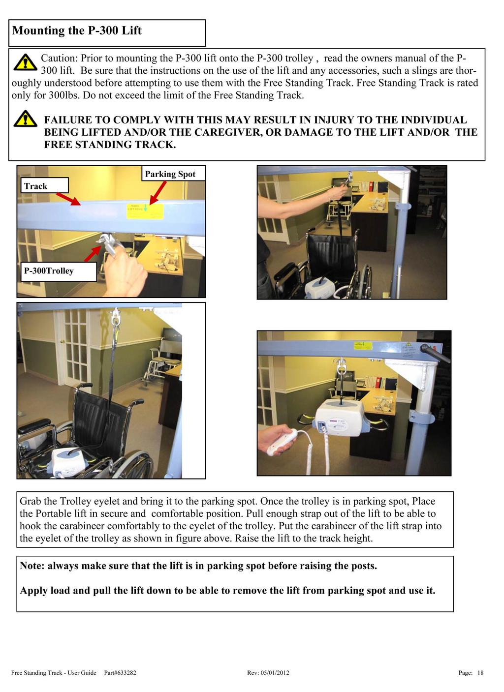

18


19 Raising up the Free Standing Track Step 1 - Grab The Post Centre to open the post clamp Step 2 - Fully Open The clamp Step 3 - Grab The Inner Post with one hand and grab the Outer Post section with the other hand. Step 4: Raise the Post Up using the height indicators. Note: When Raising the Post from Lowest setting, it is recommended to raise in 1 Foot increments. Step 5 - Repeating steps 1-5, raise the other Post. Free Standing Track - User Guide Part# Rev: 05/01/2012 Page: 19


20 Raising up the Free Standing Track Continued... Note: Free Standing Track will be in a slanting position as shown in figure. Set up the Free Standing Track by raising the post assemblies one by one. Note: a caution sign at the 7 feet indicates that you are approaching the end of the post. Carefully extend the post until you approach the stop sign or 7.5 feet if desired or applicable. Max Height of Free Standing Track Do not extend post after 7.5 Feet height mark. Note: Maximum height of Free Standing Track is 7.5 Feet. Free Standing Track - User Guide Part# Rev: 05/01/2012 Page: 20

 No Gap between Track and track Holder.")
21 Raising up the Free Standing Track Continued... Step 6 - Close the post clamp as shown in figure. Step 7 - Make sure the clamp is fully closed on both posts. Completely Installed Free Standing Track Always Before Use check the following steps: 1) Make sure the height indicator shows the same number on both posts. 2) No Gap between Track and track Holder. 3) No Gap Between Foot Pads and Floor. Free Standing Track - User Guide Part# Rev: 05/01/2012 Page: 21

22 Attaching the Skirt Optional Accessory Step 1 - Rap the skirt around the legs and close it using the Velcro hooks. Step 2 - Use the pocket as a storage for the sling or as you require. Free Standing Track - User Guide Part# Rev: 05/01/2012 Page: 22


.")
23 Disassembly of Free Standing Track Step 1 - Before disassembly, make sure the lift and /or Trolley is in parking spot. Step 2 - Grab The Post Centre to open the post clamp and fully open the clamp. Step 3 - Grab The Post and press the Ratchet with thumb. Step 4 - Bring down the Free Standing Track by sliding down the inner Post while keep pressing down the Ratchet Lock. Note: When Lowering down the Post from highest setting, it is recommended to lower in 1 Foot increments. To prevent sudden drop of the post you should release the ratchet in at least every 12 ( or every 6 holes). Failure to do this step might cause injury or damage to the floor. Free Standing Track - User Guide Part# Rev: 05/01/2012 Page: 23


24 Disassembly of Free Standing Track Note: Free Standing Track will be in a slanting position as shown in figure. Bring down the other side of the Free Standing Track following steps 2-5. Note: Make sure the posts are parallel and not twisted inside each other. Failing to do that, user might experience resistance in lowering down the posts. Safety lock Button Step 5 - Bring the Free Standing Track to the shoulder height and dismantle the lift from the trolley following the user manual of the lift. Step 6 - Push the safety lock button to unlock the track from Post assembly. Press Step 7 - Press the Push button and Twist handle in unlock direction at the same time. Step 8 - Repeat step 11 & 12 for other end to unlock the track from both ends. Free Standing Track - User Guide Part# Rev: 05/01/2012 Page: 24


25 Disassembly of Free Standing Track Step 9 - Lift The track up from post assembly and place it on the floor. Step 10 - Press the Track lock hook as shown in figure to fold the track. While holding the lock, slightly fold the track. Step 11 - Let go of the lock and fold the track. Step 16 - Close the track fully. Free Standing Track - User Guide Part# Rev: 05/01/2012 Page: 25


26 Disassembly of Legs Step 1 - Pull the hinge slightly upwards as shown in figure. Caution: Do not place your finger underneath the hinge Step 2 - Grab The side leg and press in as shown in figure. Repeat the step 1 and 2 for the other side Step 3 - Fully closed legs. Repeat the steps 1 to 3 for the other leg and post assembly. Free Standing Track - User Guide Part# Rev: 05/01/2012 Page: 26


27 Trolley Disassembly Removing Trolley C-300 (Prism part number ) Step 1 Remove the split ring as shown in figure. Step 2 Detach the hook of the C-300 by taking the pin out as shown in figure. Step 3 Make sure not to loose any part. Step 4 Fold and place the track on the floor or on a secure table. Bring the trolley to the opening of the track. Free Standing Track - User Guide Part# Rev: 05/01/2012 Page: 27


28 Trolley Disassembly Continued... Step 5 Use a screw driver and push the trolley lock button down to allow the trolley to come out. Step 6 Remove the trolley. Removing Trolley P-300 (Prism part number ) Step 1 Follow the step 1 to 6 from the removing trolley C-300. Note: Make sure not to loose any part. Free Standing Track - User Guide Part# Rev: 05/01/2012 Page: 28
29 Trouble Shooting Should problems arise with the use of the Free Standing Track review the following chart. Find the fault and complete the recommended solution. If the fault is not found and/or the solution does not correct the problem contact your local authorized dealer for service immediately. Fault Reason Recommended Solution Visually the system is not aligned straight. 1. Post is not set straight. 2. Floor is not leveled. Feet are slipping after installation. 1. Feet are not cleaned. 2. Floor is not cleaned. 1) Set up the post following Post Assembly instructions. Note: Make sure the track is seating completely flat on the track holder. 2) Foot pads must be seating completely flat on the floor. There should be no gap between the foot and floor pads. If problem persists, contact your local authorized dealer immediately. 1) Clean the feet as per Cleaning Rubber Feet Instructions. 2) Ensure floor area is dry and free of debris. If problem persists, contact your local authorized dealer immediately. Clamp Lever can not be fully closed. 1. Clamp bolt is tight 1) Open the Clamp Lever and use 3/16 Allen key to loose the bolt one turn each time. Close the clamp lever and see if closes fully. After closing the clamp press the ratchet. You should not be able to open the ratchet. If the ratchet gets open while the clamp is fully closed, it means that you have loosen the bolt too much. Tight the bolt back till you are not able to open the latch. Note: Do not loose bolt too much. If problem persists, contact your local authorized dealer immediately. The Folded Track does not sit properly on the post assemblies. Trolley does not move smoothly along the adjustable track. 1. Physical damage to track. 2. Handle lock is in lock position. 1. Physical damage to track or trolley wheels. 2. Track slots or trolley wheels are not cleaned. Trolley does not park 1. Parking hole is filled with dirt or debris. 2. Trolley spring is damaged. 3. Trolley lock button is damaged. 1) Check for physical damage to track. If so, contact local authorized dealer immediately. 2) Follow the track assembly instructions and open the handle lock. 3) Posts are not parallel or not standing completely straight. 1) Visually make sure tracks and wheels are not damaged. 2) Ensure that tracks are cleaned with cloth and free of dirt. If problem persists, contact local authorized dealer immediately. 1) Clean the hole with cloth and remove dirt or debris. 2) Contact local authorized dealer. 3) Contact local authorized dealer immediately. The folded track is not locking on the Post assembly. 1. Track Handle Lock hook damaged or broken. 2. Track Handle Lock Push button damaged or broken. Do not use the system. Contact your local authorized dealer immediately. Free Standing Track - User Guide Part# Rev: 05/01/2012 Page: 29
30 Ratchet sticks out when lowering or raising and dose not lock 1. Ratchet spring is damaged 1) Do not use the system. Contact your local authorized dealer immediately. Track Lock Not working. 1. Physical damage to track lock assembly. 2. Track Lock Spring breaks or damaged. Ratchet can be pushed out when the clamp lever is locked FAQs 1) Unfold the Track and the fold it together to see if the track lock set it self in locking position or not. If not then contact local authorized dealer immediately. 2) Do track assembly steps and see the if the track locks or not. If not then contact local authorized dealer immediately. 1. Clamp bolt is loose 1) Open the Clamp Lever and use a 3/16 Allen key to tight the bolt one turn at a time. Close the clamp lever and then push the Ratchet to see if it opens up. Note: Do not over tight the bolt. You should be still able to close the clamp lever without any problem. If problem persists, contact your local authorized dealer immediately. Question: The Free Standing Track seems unstable. Should I be worried? Answer: No. you should not be worried/concerned. Provided the Free Standing Track has been installed per the manuals specifications. After spending some time with the device, especially once a client has become accustomed to the device, the lateral stability issue will be less obvious. Question: How stable is the device? Answer: This device has been tested as per ISO requirements for Free Standing Hoists. This testing includes; a 10 degree tilts test (on all four sides) with 375lbs ( 300lbs safe working load x 1.25).The hoist has passed all testing procedures. Question: Is the device strong enough to stand the load of 300lbs? Answer: This device has been tested to maximum load of 450lbs ( 300lbs safe working load x 1.5). The hoist has passed the test with no sign of defect. Question: If the floor has a slope, will the trolley slide towards the direction of slope by itself? Answer: A braking mechanism is integrated to the design of the trolley which prevents it from sliding unintentionally. You need to apply force to be able to move the trolley to the desire location. Free Standing Track - User Guide Part# Rev: 05/01/2012 Page: 30
31 General Inspection and Maintenance Failure to follow inspection and maintenance instructions below may result in serious injury or death. Periodic general inspection and maintenance should be performed by a person who is properly qualified and trained with the use and care of The Free Standing Track System. Any defects and damage to the Free Standing Track that have lead to corrective actions should be noted and dated by the inspector. The defects and corrective actions report should be submitted in written form to the dealer. Upon Receipt of The Free Standing Track system: Ensure all the received components are according to the component list. Ensure the user manual is present otherwise do not install the Free Standing Track system. Ensure all the components are in working condition and not damaged. Ensure service record history forms are included in the package to record any completed service and repairs. Complete the Purchase and Service Information as soon as this equipment is installed. Each Use To be completed by user Prior to each use, the Free Standing Track and associated lift, accessories and sling (s), must be visually inspected. Refer to the lift, accessory and sling user guides for specific details regarding their inspection. Should any of these items below fail the inspection do not use the Free Standing Track Contact your local authorized dealer for service. Visually check for the following: Ensure all the components of Free Standing Track System are in working condition. If damaged, please contact the dealer for replacement before use. All 4 feet are on a stable, level surface and the supporting post assemblies are secure. Check rubber feet for damages. If damage is noticed, please contact dealer for replacement. Make sure that they are clean before placing them on the floor. ( refer to cleaning rubber feet instruction) The Post clamps are locked. The ratchets are locked The handles are locked The trolley moves easily along the track. The adjustment track is placed in the correct location for transferring. Ensure the labels are legible and in good condition. If not contact dealer for replacement. Record the service record history form for any completed service and repairs. Ensure that the service record is signed and dated each time it is used. The portable lift has been inspected as outlined in it s owners manual. The sling (s) has been inspected as outlined in it s owners manual. Free Standing Track - User Guide Part# Rev: 05/01/2012 Page: 31
32 Service Record History - Initial Information Complete the following section- Purchase and Service Information as soon as this equipment is installed. Use the service record history to record any completed service and repairs. Ensure that the service record is signed and dated each time it is used. Be sure to have this piece of equipment serviced on a regular basis as described in the General Inspection and Maintenance Section PURCHASE INFORMATION: Free Standing Track System Product Name: Serial#: Date of Purchase: Date Installed: Purchased From: Address: City: Post Code: Telephone No: Comments: SERVICE INFORMATION: Contact the following company for service: Company: Address: City: Post Code: Telephone No: Comments: Free Standing Track - User Guide Part# Rev: 05/01/2012 Page: 32
33 Service Record History Complete this section after each service, repair inspection and/ or maintenance. Photocopy additional pages as required. Date: Time: Service Type: Periodic Inspection Monthly Inspection 6 Month Inspection Repair Yearly Inspection Other: Completed By: Printed Name Signature Company: Remarks & Action Taken: Date: Time: Service Type: Periodic Inspection Monthly Inspection 6 Month Inspection Repair Yearly Inspection Other: Completed By: Printed Name Signature Company: Remarks & Action Taken: Date: Time: Service Type: Periodic Inspection Monthly Inspection 6 Month Inspection Repair Yearly Inspection Other: Completed By: Printed Name Signature Company: Remarks & Action Taken: Date: Time: Service Type: Periodic Inspection Monthly Inspection 6 Month Inspection Repair Yearly Inspection Other: Completed By: Printed Name Signature Company: Remarks & Action Taken: Date: Time: Service Type: Periodic Inspection Monthly Inspection 6 Month Inspection Repair Yearly Inspection Other: Completed By: Printed Name Signature Company: Remarks & Action Taken: Date: Time: Service Type: Periodic Inspection Monthly Inspection 6 Month Inspection Repair Yearly Inspection Other: Completed By: Printed Name Signature Company: Remarks & Action Taken: Free Standing Track - User Guide Part# Rev: 05/01/2012 Page: 33
34 Service Record History Complete this section after each service, repair inspection and/ or maintenance. Photocopy additional pages as required. Date: Time: Service Type: Periodic Inspection Monthly Inspection 6 Month Inspection Repair Yearly Inspection Other: Completed By: Printed Name Signature Company: Remarks & Action Taken: Date: Time: Service Type: Periodic Inspection Monthly Inspection 6 Month Inspection Repair Yearly Inspection Other: Completed By: Printed Name Signature Company: Remarks & Action Taken: Date: Time: Service Type: Periodic Inspection Monthly Inspection 6 Month Inspection Repair Yearly Inspection Other: Completed By: Printed Name Signature Company: Remarks & Action Taken: Date: Time: Service Type: Periodic Inspection Monthly Inspection 6 Month Inspection Repair Yearly Inspection Other: Completed By: Printed Name Signature Company: Remarks & Action Taken: Date: Time: Service Type: Periodic Inspection Monthly Inspection 6 Month Inspection Repair Yearly Inspection Other: Completed By: Printed Name Signature Company: Remarks & Action Taken: Date: Time: Service Type: Periodic Inspection Monthly Inspection 6 Month Inspection Repair Yearly Inspection Other: Completed By: Printed Name Signature Company: Remarks & Action Taken: Free Standing Track - User Guide Part# Rev: 05/01/2012 Page: 34
35 Service Record History Complete this section after each service, repair inspection and/ or maintenance. Photocopy additional pages as required. Date: Time: Service Type: Periodic Inspection Monthly Inspection 6 Month Inspection Repair Yearly Inspection Other: Completed By: Printed Name Signature Company: Remarks & Action Taken: Date: Time: Service Type: Periodic Inspection Monthly Inspection 6 Month Inspection Repair Yearly Inspection Other: Completed By: Printed Name Signature Company: Remarks & Action Taken: Date: Time: Service Type: Periodic Inspection Monthly Inspection 6 Month Inspection Repair Yearly Inspection Other: Completed By: Printed Name Signature Company: Remarks & Action Taken: Date: Time: Service Type: Periodic Inspection Monthly Inspection 6 Month Inspection Repair Yearly Inspection Other: Completed By: Printed Name Signature Company: Remarks & Action Taken: Date: Time: Service Type: Periodic Inspection Monthly Inspection 6 Month Inspection Repair Yearly Inspection Other: Completed By: Printed Name Signature Company: Remarks & Action Taken: Date: Time: Service Type: Periodic Inspection Monthly Inspection 6 Month Inspection Repair Yearly Inspection Other: Completed By: Printed Name Signature Company: Remarks & Action Taken: Free Standing Track - User Guide Part# Rev: 05/01/2012 Page: 35

36 If you have any questions about the manufacture or operation of this equipment, please contact Vancare, or your local authorized dealer. Manufactured for: Vancare, Inc st Street Aurora, NE Telephone: (402) Fax: (402) Toll Free: Free-Standing Track- User Guide Rev: 2/06/09 Page: 36
37 VANCARE Ceiling lift Skills Observation Assessment Staff Member Observed Date PROCEDURE - DID THE EMPLOYEE: Select the correct size sling? Have the required number of staff members present? Inspect the sling and lift for damage and proper operation? If DAMAGED, did the employee get another lift/sling and notify charge nurse? Correctly position the sling so that the bottom center of the sling is at the tailbone? Perform environment assessment and move objects that would impede operation of lift? Move the lift into position with the hanger bar in the H position in front of the resident and the base properly opened? Properly use the locking casters (locking only on ramped surfaces )? Lower the lift using the Pendant Switch? Connect the sling loops to the hanger bar hooks? Use the same loops on each side? Double check the sling attachment to the lift? Lift the resident only as high as necessary? Moving the lifter with a patient in the sling? (1 person pushes lift, while the other controls the resident, using the hand-loops.) Lower the lift until the resident is sitting on the chair or lying on the bed? Remove the sling loops from the hanger bar hooks, and prevent the hanger bars from coming in contact with the patient? Back the lift away from the resident and remove the sling? Make certain the resident is safe and comfortable before leaving? KNOWLEDGE CAN THE EMPLOYEE: Properly use the Scale attachment? Identify lifting capabilities (maximum weight)? Identify location and use of Emergency Stop Switch? Identify location and use of Emergency Lowering? Identify location and use of Auxiliary Up/Down Switch? Identify Low Battery Indicator light and/or LCD Battery Display? Demonstrate how and when to recharge batteries? Identify sling parts: head support, shoulder loops, leg supports, leg loops, stabilizing handles? Demonstrate ability to adjust angle of recline to maintain hip precautions? Demonstrate transfer of patient, using Vancare ceiling lift, from bed to to chair, chair to bed, and floor to bed? Demonstrate proper understanding of how to clean the sling and lift? Refer to Operator s Manual for more detailed description of transfer technique. Pass Fail Observations Observer s Name Observer s Signature
Sequoia 2 Post System
 Sequoia 2 Post System Owner s Manual Use and Care Fault Finding Warranty Information Table of Contents Sequoia 2 Post System Introduction... 3 Overview... 3 Placement of the Sequoia... 4 Components of
FGSH-450 by Prism Medical
 FGSH-450 by Prism Medical Introduction... 2 Overview... 2 Components of the Floor Lift... 3 Specifications... 4 Cautions... 5 Shipping & Transportation Instruction... 6 Assembly Instruction......7 Operation
SGA-440 by Prism Medical
 SGA-440 by Prism Medical Introduction... 2 Overview... 2 Components of the Sit to Stand Lift... 3 Component List... 4 Specifications... 5 Cautions... 6 Assembly Instruction... 7 Operation Charging......12
Prism A-205. Owner s Manual. Aluminium Mobile Hoist. Use and Care Trouble Shooting Warranty Information. Introduction Overview...
 Prism A-205 Aluminium Mobile Hoist Introduction... 2 Overview... 2 Components of the Mobile hoist... 3 Component List... 4 Specifications... 5 Cautions... 6 Assembly Instruction... 7 Operation Charging......13
P-440. Use and Care Fault Finding Warranty Information
 P-440 Owner s Manual Use and Care Fault Finding Warranty Information Waverley Glen Systems, Ltd. 87 Sharer Road, Vaughan, ON L4L 8Z3 T (905) 850-0093 F (905) 850-8377 1-800-265-0677 info@waverleyglen.com
Apollo Tilt Wheelchair 18" and 20" Instruction Manual
 Apollo Tilt Wheelchair 18" and 20" Instruction Manual Table of Contents Contents Table of Contents... 2 Introduction... 3 Warning... 4 Safety Guidelines... 5 Parts of the Tilt Wheelchair... 6 Setup & Operation...
Owners Manual Unilift
 Owners Manual Unilift Contents Chapter Page Introduction 2 Safety Advise 3 Warranty 4 Using the Unilift 5 Fitting the Sling 6 Lifting and lowering 7 Emergency Controls 8 Battery and Charging Systems 9
Owner s Manual. Bariatric Manual Wheelchairs. Specializing in Bariatric Patient Aids
 Owner s Manual Bariatric Manual Wheelchairs 700 LB CAPACITY XL Series Wheelchair by ConvaQuip Specializing in Bariatric Patient Aids P.O. Box 3417 * Abilene, TX 79604 U.S.A. Toll 800/637-8436 * FAX 325/677-7217
Heavy Duty Four Wheeled Walker
 Heavy Duty Four Wheeled Walker Weight Capacity: 500 lbs. ITEM # W1802 Made in China 2011 ESSENTIAL MEDICAL SUPPLY, INC. Manufactured for Orlando, FL 32822 -- SAVE THESE INSTRUCTIONS -- Do not attempt to
Breezy EC Transport Wheelchair
 B r e e z y E C Tr a n s p o r t W h e e l c h a i r Breezy EC Transport Wheelchair O w n e r s M a n u a l READ BEFORE USE REVIEW THIS MANUAL Before using this chair you, and each person who may assist
Owner s Manual. Transport / Companion Wheelchairs M4TV M2TF M2TC M2TL HEALTH PRODUCTS, INC.
 Owner s Manual M4TV M2TF Transport / Companion Wheelchairs M2TL M2TC HEALTH PRODUCTS, INC. INTRODUCTION Congratulations on the purchase of your new companion chair. Please read this introduction with your
USER MANUAL PRODUCT CODE: WC CareCo (UK) Ltd, Hubert Road, Brentwood, Essex, CM14 4JE PAGE 1
 Ltd, Hubert Road, Brentwood, Essex, CM14 4JE PAGE 1") by USER MANUAL PRODUCT CODE: WC01059 CareCo (UK) Ltd, Hubert Road, Brentwood, Essex, CM14 4JE PAGE 1 CONTENTS 1. INTRODUCTION 2. IDENTIFICATION OF PARTS 3. SAFETY REGULATIONS 4. SAFETY WARNINGS 5. USER
by USER MANUAL PRODUCT CODE: WC01059 CareCo (UK) Ltd, Hubert Road, Brentwood, Essex, CM14 4JE PAGE 1 CONTENTS 1. INTRODUCTION 2. IDENTIFICATION OF PARTS 3. SAFETY REGULATIONS 4. SAFETY WARNINGS 5. USER
Compact Easy Rollator M66739
 User Instructions Compact Easy Rollator M66739 Maximum Safe Working Load 21st 135kg Please ensure these Instructions are fully read and understood before using this equipment. Retain these instructions
Euro Lightweight Wheeled Walker
 Euro Lightweight Wheeled Walker Handle with lever brake Backrest Brake cable Handle height adjustment button Removable shopping bag 8 inch (200 mm) wheels Cane holder user guide Prior to use please read
Mighty Mack Wheeled Walker
 Mighty Mack Wheeled Walker Handle with lever brake Backrest Handle height adjustment knob Brake cable Extra wide padded seat Shopping basket Side brace 7 inch (180 mm) wheels user guide Prior to use please
The Future of Homecare Lifting is Here!
 HYDRAULIC OR BATTERY OPERATED MODEL:400H / 400EL / 400LK The Future of Homecare Lifting is Here! Thank you for choosing the BestLift 400 To better serve you, please record the following information: Dealer
Nimbo Lightweight Posterior Posture Walker
 Nimbo Lightweight Posterior Posture Walker Assembly & Operating Instructions with optional Forearm Platforms with optional Pelvic Stabiliser Please read these instructions carefully before assembling or
ALUMINUM CARGO CARRIER WITH FOLDING RAMP
 ALUMINUM CARGO CARRIER WITH FOLDING RAMP OWNER S MANUAL WARNING: Read carefully and understand all ASSEMBLY AND OPERATION INSTRUCTIONS before operating. Failure to follow the safety rules and other basic
Push Down Wheeled Walker
 Push Down Wheeled Walker Push down hand grip Handle height adjustment knob Backrest Padded seat with concealed pouch Side brace Bag with shopping basket inside Push down brake stopper 6 inch (150 mm) wheels
DWHOIST. Drywall Hoist Assembly & Operating Instructions
 DWHOIST Drywall Hoist Assembly & Operating Instructions READ ALL INSTRUCTIONS AND WARNINGS BEFORE USING THIS PRODUCT. SAVE THESE INSTRUCTIONS FOR FUTURE REFERENCE. This manual provides important information
Uplift Power Seat Users Guide
 Safety Precautions 1. Use the Uplift Power Seat only in armchairs or sofas with at least one armrest for optimum stability when sitting or rising. 2. Uplift Power Seat is not intended for use in rocking
Package Contents Part A (3) I-Beam (1) Base (2) Other parts
 I-Beam (1) Base (2) Other parts") Page 1 Installation Instructions for 81245 Adjustable Height Gantry Crane 1-Ton Capacity Table of Contents Important Safety Information pg. 2 Specific Operation Warnings pg. 2 Main Parts of Product pg.
Page 1 Installation Instructions for 81245 Adjustable Height Gantry Crane 1-Ton Capacity Table of Contents Important Safety Information pg. 2 Specific Operation Warnings pg. 2 Main Parts of Product pg.
On-A-Roll Lifter Instruction Manual for Standard Models Read Before Use!
 On-A-Roll Lifter Instruction Manual for Standard Models Read Before Use! Important instructional, safety and precautionary information! It is the user s responsibility to exercise good judgment, common
USER MANUAL. Item: #13246 Stand-Aid Lift. Drive Medical Design and Manufacturing
 USER MANUAL Item: #13246 Stand-Aid Lift IMPORTANT SAFEGUARDS Your lift is for transferring patients only. Do not use the lift for any other purpose. Stand-Aid Lift is intended to be used for persons within
2,000 Lbs Heavy-Duty Engine Stand
 ITEM#: TR29005 2,000 Lbs Heavy-Duty Engine Stand WARNING: Read carefully and understand all ASSEMBLY AND OPERATION INSTRUCTIONS before operating. Failure to follow the safety rules and other basic safety
Advancement Chair. R901, R902, & R903 Product Manual
 Advancement Chair R901, R902, & R903 Product Manual Contents Warnings and Important Information 3 Recommended Use 4 User and Item Dimensions 4 Assembly and Adjustment Information 5 Maintenance 14 Cleaning
A935 OWNER'S MANUAL ASSEMBLY INSTRUCTIONS
 2013.02 A935 OWNER'S MANUAL ASSEMBLY INSTRUCTIONS A. SAFETY INSTRUCTIONS Read all cautions/warnings and obtain proper instruction on use of the machines prior to using. Use appropriate positioning and
Booster Car Seat User Guide
 Booster Car Seat User Guide For future use, STORE USER GUIDE in location on bottom of base. IS0133.E 2015 Artsana USA, Inc. If you have any problems with your Chicco Booster Seat, or any questions regarding
Marlin Bath Lift BLM-8200 WARNING! Read ALL instructions before using this product!
 Marlin Bath Lift BLM-8200 www.inspiredbydrive.com WARNING! Read ALL instructions before using this product! PRODUCT DESCRIPTIONS Your Marlin Bath Lift has been built to the highest standards of quality
Tri-Wheel Wheeled Walker
 Tri-Wheel Wheeled Walker Handle with lever brake Brake cable Handle height adjustment knob Removable basket and tray Large vinyl bag 8 inch (203 mm) wheels user guide Prior to use please read all instructions.
Prime Engineering GRANSTAND II
 OWNER S MANUAL PRODUCT PHOTO PARTS LIST ASSEMBLY INSTRUCTIONS FITTING & ADJUSTING DAILY USAGE ACCESSORIES MAINTENANCE WARRANTY Prime Engineering GRANSTAND II Manufactured By Prime Engineering A Division
Owners Manual POWER PLUS MOBILITY OUR PRODUCTS WILL MOVE YOU
 Owners Manual POWER PLUS MOBILITY OUR PRODUCTS WILL MOVE YOU At Power Plus Mobility, we care! Thank you for choosing a wheelchair from Power Plus Mobility Inc. We are always improving in our ways to serve
Before equipment use, please read this operation manual carefully. Serial Number: Date Purchased:
 Pushed & Geared Trolleys OPERATION MANUAL This operation manual is intended as an instruction manual for trained personnel who are in charge of installation, maintenance, repair etc. Before equipment use,
DOC /500/600 Series Sit to Stand Lift Owner's Manual REV 001
 Page1 BESTCARE MODELS COVERED BestStand 400 Series Sit to Stand BestStand 500 Series Sit to Stand BestStand 600 Series Sit to Stand CONTENTS Product Features Assembly Operating Instructions Warranty BEFORE
QUALITY TESTED PRODUCT OWNERS MANUAL
 TM Est. 1965 QUALITY TESTED PRODUCT OWNERS MANUAL TM Est. 1965 This product is made in Australia by TOPFORM FURNITURE Pty Ltd who are a member of the FIAA and a signatory to the Residential Furnishing
Low Profile Wrenches Operation and Maintenance Manual
 Low Profile Wrenches Operation and Maintenance Manual http://www.torquetoolsinc.com Use the HEXPRO Series Low Profile Wrenches Model 2HP 4HP 8HP 14HP 30HP to install and remove large bolts that have minimal
Backs and Support OWNER MANUAL. J&L Hardware. TFB Hardware J&L Owner s Manual
 Backs and Support OWNER MANUAL J&L Hardware TFB Hardware J&L Owner s Manual Customer Satisfaction 1.0 Stealth Products strives for 100% customer satisfaction. Your complete satisfaction is important. Please
Two Seat Bicycle Trailer
 Two Seat Bicycle Trailer User s Manual This manual contains safety, assembly, use and maintenance instructions. Read these instructions carefully before use and keep them for future reference. Your child
USER MANUAL. Item: #13246 Stand-Aid Lift. Drive Medical Design and Manufacturing Push Handle. Base Width Adjustment Handle.
 USER MANUAL Item: #13246 Stand-Aid Lift Push Handle Base Width Adjustment Handle Mast Sling Attachment Hook Adjustable Knee Pad Front Caster W/Brake Foot Plate Front Caster W/O Brake Rev1.06.11.14 IMPORTANT
(H) TOUR VANTAGE STROLLER ASSEMBLY INSTRUCTIONS ADULT ASSEMBLY REQUIRED. Styles and colors may vary
 TOUR VANTAGE STROLLER ASSEMBLY INSTRUCTIONS ADULT ASSEMBLY REQUIRED. Styles and colors may vary") TOUR VANTAGE STROLLER ASSEMBLY INSTRUCTIONS ADULT ASSEMBLY REQUIRED Styles and colors may vary IMPORTANT: Read all instructions before assembly and use of the stroller Keep the instructions for future
TOUR VANTAGE STROLLER ASSEMBLY INSTRUCTIONS ADULT ASSEMBLY REQUIRED Styles and colors may vary IMPORTANT: Read all instructions before assembly and use of the stroller Keep the instructions for future
PN: 6410T0022 Rev. 8/18/2014 Revision D Albany RR300 Stainless Mechanical Install & Owner s Manual
 PN: 6410T0022 Rev. 8/18/2014 Revision D Albany RR300 Stainless Mechanical Install & Owner s Manual ASSA ABLOY ENTRANCE SYSTEM. All Rights Reserved 975-A Old Norcross Road, Lawrenceville, Georgia 30046
Quick Release Mounting Hardware
 Mounting Hardware USER MANUAL Quick Release Mounting Hardware Stealth s User Manual and Maintenance Guide for ADI s Quick Release Mounting Hardware Customer Satisfaction 1.0 Stealth Products strives for
UniLink Elbow Support Hardware
 Upper Extremities OWNER MANUAL UniLink Elbow Support Hardware UniLink Elbow Hardware Owner s Manual Customer Satisfaction 1.0 Stealth Products strives for 100% customer satisfaction. Your complete satisfaction
Single Seat Trailer. Owner s manual and safety instructions
 Single Seat Trailer Owner s manual and safety instructions Owner s Manual Every effort has been made to ensure your trailer is of top quality and proven safe design, ready to provide you with many years
Spirit Trailer with stroller attachment
 Spirit Trailer with stroller attachment User s Manual This manual contains safety, assembly, use and maintenance instructions. Read these instructions carefully before use and keep them for future reference.
REACH USER MANUAL USER: READ THIS MANUAL BEFORE USING THIS DEPENDENT MOBILITY BASE AND SAVE FOR FUTURE REFERENCE
 USER MANUAL CHAIR PROVIDER: THIS MANUAL MUST BE GIVEN TO THE USER OF THIS DEPENDENT MOBILITY BASE USER: READ THIS MANUAL BEFORE USING THIS DEPENDENT MOBILITY BASE AND SAVE FOR FUTURE REFERENCE Revision
OPERATION AND MAINTENANCE MANUAL FOR 3002-SERIES ULTRALINER FRAME MACHINES
 OPERATION AND MAINTENANCE MANUAL FOR 3002-SERIES ULTRALINER FRAME MACHINES CONTENTS: 1. GENERAL INFORMATION 2. OPERATION 3. MAINTENANCE 4. SAFETY WARNINGS 5. WARRANTY NOTES: Please read this entire manual
Installation and Service Manual
 RAVE Star Lift Installation and Service Manual WARNING! STRICT ADHERENCE TO THESE INSTALLATION INSTRUCTIONS is required and will promote the safety of those installing this product, as well as those who
K710 Product Manual. Support Station. K710 Product Manual
 K710 Product Manual Support Station K710 Product Manual Contents Important information 2 Safety messages 3 Recommended use 4 Item dimensions 5 Check your order 6 Installation 6 Basic components 7 Accessories
Liko M220 / Liko M230
 Liko M220 / Liko M230 Instruction Guide English 7EN150106-04 2012-03-06 Applies to the following models: Liko M220 Prod. no. 2050010 Liko M230 Prod. no. 2050015 Liko M230 Product Description Liko M220
IBT Series Square Drive Torque Wrenches
 IBT Series Square Drive Torque Wrenches Operation and Maintenance Manual Model.75, 1, 3, 5, 8, 10, 20, 25, 35, 50 http://www.torsionx.com Use the IBT Series Square Drive Torque Wrenches Model.75, 1, 3,
OPERATOR S MANUAL 2200 SERIES LIFT - LIL HOISTER. July 2017
 July 2017 OPERATOR S MANUAL 2200 SERIES LIFT - LIL HOISTER! Before operating this lift, read and understand this Operator s Manual. Become familiar with the potential hazards of this unit. Call SUMNER
UltraSlim Mechanical Install & Owner s Manual
 PN: 6410T0020 Version C Rev: 5/01/2012 UltraSlim Mechanical Install & Owner s Manual Doors are Ultra-Tough, Ultra-Reliable, and Ultra-Affordable. ASSA ABLOY ENTRANCE SYSTEMS All Rights Reserved 975-A Old
C300/P300. Technical Manual
 C300/P300 By Vancare Technical Manual Manufactured for: VANCARE, INC. 1515 1ST STREET, AURORA, NE 68818 T (800) 694-4525 F (402) 694-3994 info@vancare.com www.vancare.com P300/C300 Technical Manual REV
USER MANUAL. CareCo (UK) Ltd, Hubert Road, Brentwood, Essex, CM14 4JE PAGE 1 PRODUCT CODE WC01060.BLU
 Ltd, Hubert Road, Brentwood, Essex, CM14 4JE PAGE 1 PRODUCT CODE WC01060.BLU") by USER MANUAL PRODUCT CODE WC01060.BLU PAGE 1 CareCo (UK) Ltd, Hubert Road, Brentwood, Essex, CM14 4JE INFORMATION Thank you for purchasing a wheelchair from I-GO. This I-GO wheelchair has been designed
by USER MANUAL PRODUCT CODE WC01060.BLU PAGE 1 CareCo (UK) Ltd, Hubert Road, Brentwood, Essex, CM14 4JE INFORMATION Thank you for purchasing a wheelchair from I-GO. This I-GO wheelchair has been designed
Healthy Care High Chair
 Healthy Care High Chair Product features and decoration may vary from the photo above. Model Number: 79638, 79639, 79640, 79641, B2875 Please keep this instruction sheet for future reference, as it contains
2 in 1 Rollator and Transit Chair M58203
 User Instructions 2 in 1 Rollator and Transit Chair M58203 Maximum Safe Working Load Please ensure these Instructions are fully read and understood before using this equipment. Retain these instructions
HitchHoist Assembly & Operating Instructions IMPORTANT NOTICE
 HitchHoist Assembly & Operating Instructions IMPORTANT NOTICE FAILURE TO READ AND COMPLY WITH THE INSTRUCTIONS PRINTED IN THIS MANUAL COULD RESULT IN SERIOUS INJURY! IT IS STRONGLY RECOMMENDED THAT PERSONNEL
MODEL 7400 STRUT SPRING COMPRESSOR
 MODEL 7400 STRUT SPRING COMPRESSOR Installation, Operation & Repair Parts Information Branick Industries, Inc. 4245 Main Avenue P.O. Box 1937 Fargo, North Dakota 58103 REV112712 P/N: 81-0103A TABLE OF
 Operation and Maintenance Manual http://www.torsionx.eu Use the MaxDrv Series Square Drive Torque Wrench Model.75, 1, 3, 5, 8, 10, 20, 25, 35, 50 to install and remove threaded fasteners requiring precise
2000-LB. ENGINE STAND
 2000-LB. ENGINE STAND WARNING: Read carefully and understand all ASSEMBLY AND OPERATION INSTRUCTIONS before operating. Failure to follow the safety rules and other basic safety precautions may result in
Dealer Stamp. Rollator (R6 and R8) Assembly & Operating Instructions
 Assembly & Operating Instructions") The manufacturer reserves the right to alter without notice any weights, measurements or other technical data shown in this manual. All figures, measurements and capacities shown in this manual are approximate
The manufacturer reserves the right to alter without notice any weights, measurements or other technical data shown in this manual. All figures, measurements and capacities shown in this manual are approximate
Responsible Unit: Facilities Management
 Policy Sponsor: Assistant Vice President Approval Date: January 2010 Mobile Overhead Cranes Safe Work Instructions Responsible Unit: Revisions: Service: Trade Services Shop: Mechanical & Welding Hazards
Booster Car Seat. User Guide. in location on bottom of base. IS0174E_ Artsana USA, Inc. 01/19
 Booster Car Seat User Guide For future use, STORE USER GUIDE in location on bottom of base. IS0174E_03 2019 Artsana USA, Inc. 01/19 www.chiccousa.com TABLE OF CONTENTS If you have any problems with your
WHEELED WALKER OWNER S HANDBOOK
 CONTENTS 1. Contents 2. Introduction 3. Parts Description 4. Personal Safety 5. Adjustments for Comfort 6. Transportation & Assembly 7. Care and Maintenance 8. Brake Operation 9. Assembling the Walker
MODEL 7600 STRUT SPRING COMPRESSOR
 MODEL 7600 STRUT SPRING COMPRESSOR Installation, Operation & Repair Parts Information Branick Industries, Inc. 4245 Main Avenue P.O. Box 1937 Fargo, North Dakota 58103 REV6162014 P/N: 81-0246 TABLE OF
IMPORTANT! KEEP INSTRUCTIONS FOR FUTURE REFERENCE.
 T1838 IMPORTANT! KEEP INSTRUCTIONS FOR FUTURE REFERENCE. www.fisher-price.com.au Consumer Information WARNING Prevent serious injury or death from falls or sliding out: Always use the restraint system
S-Drive Performance Trainer
 S-Drive Performance Trainer SERVICE MANUAl Table of contents CHAPTER 1: Serial number location... 1 CHAPTER 2: Important Safety instructions 2.1 Read and Save These Instructions... 2 2.2 Before Getting
GoFitTM. Booster Car Seat User Guide. in location on bottom of base. IS0147E_ Artsana USA, Inc. 01/19
 GoFitTM Booster Car Seat User Guide For future use, STORE USER GUIDE in location on bottom of base. IS047E_04 209 Artsana USA, Inc. 0/9 www.chiccousa.com TABLE OF CONTENTS If you have any problems with
adopts a holistic approach to patient transfers and is organized in four categories: transfer, positioning, support and lifting.
 Manual - English 1 3 4 5 6 7 2 13 11 12 9 1. Boom 2. Mast 3. Handlebar 4. Battery pack 5. Emergency stop 6. Control box 7. Motor for base-width adjustment 8. Rear castors with brakes 9. SlingBar with safety
RUFNEX Series Low Profile Wrenches Operation and Maintenance Manual
 RUFNEX Series Low Profile Wrenches Operation and Maintenance Manual http://www.torsionx.com Use the RUFNEX Series Ultra-Low Profile Wrenches to install and remove large bolts that have minimal wrench clearance.
INSTRUCTIONS AND WARRANTY FOR THE STAND AID MODEL 1501 STAND AID SERIAL #
 MAKERS OF STAND AID AND ROLL AID STAND AID MODEL 1501 PO BOX 386 Sheldon, IA 51201 1-800-831-8580 1-712-324-2153 (In Iowa) Fax: 712-324-5210 INSTRUCTIONS AND WARRANTY FOR THE STAND AID MODEL 1501 STAND
User Guide MDS86850E MDS86850EB Rollator
 Supplying Hospitals for Over 90 Years User Guide MDS86850E MDS86850EB Rollator Revised: May 06, 2009 Safety Instructions To ensure your safety in using the Medline rollator, the following safety information
HexPro Series Low Profile Wrenches
 HexPro Series Low Profile Wrenches Operation and Maintenance Manual Model 2HP 4HP 8HP 14HP 30HP www.torquetoolsinc.com Use the HEXPRO Series Low Profile Wrenches Model 2HP 4HP 8HP 14HP 30HP to install
XChange Seat Service and Maintenance Guide
 XChange Seat Service and Maintenance Guide Table Of Contents Page General Information... 1 Registration Information... 1 Seat Cushion Latch... 2 Lap Shoulder Belt Replacement... 2 Sliding Buckles Replacement...
190/195 Tilt Shower Commode User Manual
 ... 190/195 Tilt Shower Commode User Manual Healthline Products 1065 E Story Rd Winter Garden Florida 34787 Fax 407-656-5641 Toll Free: 800-987-3577 Product Information This series of rehab commodes offer
Petite Wheeled Walker
 Petite Wheeled Walker Handle with lever brake Brake cable Handle height adjustment knob Backrest Padded seat with concealed pouch Bag with shopping basket inside Side brace 6 inch (150 mm) wheels user
 Operation and Maintenance Manual Model.75,, 3, 5, 8, 0, 0, 5, 35, 50 http://www.torsionx.com Use the MaxDrv Series Square Drive Torque Wrench Model.75,, 3, 5, 8, 0, 0, 5, 35, 50 to install and remove threaded
SB2 TubBuddy Owners Manual. elimination through innovation
 SB2 TubBuddy Owners Manual elimination through innovation contents Exploded Parts... 3 Parts List... 4 Securing Clip Sizes... 4 TubBuddy Assembly... 5 TubBuddy Setup... 12 TubBuddy Operation... 17 Cleaning
Able Assist Transfer Aids User Manual
 www.drivemedical.co.uk The Team at Drive Medical develops its products to give our customers the freedom to live independently. This encompasses their daily home life and provides them with the opportunity
TXJ0500/RR500 1,000-lbs. Truck Bed Roller Dolly
 OWNER S MANUAL TXJ0500/RR500 1,000-lbs. Truck Bed Roller Dolly WARNING: Questions, problems, missing parts? Before returning to your retailer, call our customer service department at 1-888-448-6746, 8
Rocket. Two Seat Bicycle Trailer. Model Number ACIS99ROCKTBLU
 Rocket Two Seat Bicycle Trailer Model Number ACIS99ROCKTBLU User s Manual This manual contains safety, assembly, use and maintenance instructions. Read these instructions carefully before use and keep
USER AND SAFETY MANUAL
 USER AND SAFETY MANUAL HANDLE- BARS STEM COLLAR ROD SADDLE SAFETY HOOK- STRIP BRAKE SUPPORT BARS AFT TUBE FRONT TUBE SAFETY RULES SECURE THE ROD AND ATTACH SAFETY HOOK-STRIP before every ride. RIDE WHEELA
expandable booster Instruction Manual US Version
 expandable booster Instruction Manual US Version product: monterey expandable booster model series: 15000 mfg. by: Diono LLC 14810 Puyallup Avenue Sumner, WA 98390 Customer Care Tel: 1 (855) 463-4666 us.diono.com
TABLE OF CONTENTS Safe Use Checklist Registration & Recal Assistance Warnings Base Features Carrier Features Securing Child In Carrier
 TABLE OF CONTENTS Safe Use Checklist...4 Registration & Recall...5 Assistance...5 Warnings...6 Base Features Base Overview... Storage Compartment...3 Recline Adjustment...3 LATCH Removal & Storage...4
BATTERY OPERATED PATIENT LIFT MODEL:650HD OWNER S MANUAL
 BATTERY OPERATED PATIENT LIFT MODEL:650HD OWNER S MANUAL Thank you for choosing BestcareLift! To better serve you, please record the following information: Supplier Name: Telephone: Serial #: Date of Purchase:
GoFitTM. Booster Car Seat User Guide. in location on bottom of base. IS0147.2E Artsana USA, Inc.
 GoFitTM Booster Car Seat User Guide For future use, STORE USER GUIDE in location on bottom of base. IS047.2E 207 Artsana USA, Inc. www.chiccousa.com TABLE OF CONTENTS If you have any problems with your
User Guide. Always abide by this User Guide
 User Guide This User Guide and all the safety instructions must be read and adhered to before use of the StrideOn. For questions, please contact the place of purchase/rental or call StrideOn Australia
Wallace Tri-Adjustable Gantry Cranes Square Tube Assembly Instructions
 Wallace Tri-Adjustable Gantry Cranes Square Tube Assembly Instructions For any additional information, Please call 1- S 1. Read and understand instructions before using this gantry. 2. Inspect gantry thoroughly
This is the way your new rollator works
 This is the way your new rollator works Volaris S7 User Manual Volaris S7 Art. no. 1 422 150 1 Congratulations to your new rollator! The Volaris S7 will in many ways simplify your daily life. Acquaint
Talon. Assembly, Mounting And Operating Manual. Thank you for purchasing the
 And Operating Manual Thank you for purchasing the VARILITE. Because a back system can have a dramatic impact on a person s quality of life, we recommend consulting a therapist or seating specialist who
Operator s Manual. Single Hand Manual Drive Wheelchair
 Operator s Manual Single Hand Manual Drive Wheelchair Jordan R. Smith Kayla Gosse Leah McElhaney Team #5 Project for Client: Danielle Giroux Client Contact Information: Dave and Suzanne Giroux 53 Charlotte
PRISM MEDICAL UK SA160C STAND AID
 PRISM MEDICAL UK SA160C STAND AID USER GUIDE Unit 1, Tir Llwyd Industrial Estate, St Asaph Avenue, Kinmel Bay, Nr Rhyl, Conwy, LL18 5JZ info@prismmedical.co.uk Tel +44 (0)1924 840100 www.prismmedical.co.uk
SUS9 Swing Away Series
 Positioning & Support USER MANUAL SUS9 Swing Away Series Stealth s User Manual and Maintenance Guide for the SUS9 Swing Away Series Customer Satisfaction 1.0 Stealth Products strives for 100% customer
48 in. DELUXE ALUMINUM CARGO CARRIER WITH RAMP
 48 in. DELUXE ALUMINUM CARGO CARRIER WITH RAMP OWNER S MANUAL WARNING: Read carefully and understand all ASSEMBLY AND OPERATION INSTRUCTIONS before operating. Failure to follow the safety rules and other
INSTRUCTIONS AND WARRANTY FOR THE STAND AID MODEL 1501 STAND AID SERIAL #
 MAKERS OF STAND AID, PTA, FREEDOM CHAIR STAND AID MODEL 1501 PO BOX 386 Sheldon, IA 51201 1-800-831-8580 1-712-324-2153 (In Iowa) Fax: 712-324-5210 www.stand-aid.com INSTRUCTIONS AND WARRANTY FOR THE STAND
CAUTION -TABLE OF CONTENTS- II. OPERATING INSTRUCTIONS
 -PRINT- -TABLE OF CONTENTS- II. OPERATING INSTRUCTIONS his chapter contains safety precautions, daily safety check instructions, control and indicator descriptions, and operating instructions that apply
KidWalk KidWalk II Dynamic Mobility System
 OWNER S MANUAL KidWalk KidWalk II Dynamic Mobility System Manufactured By Prime Engineering A Division of Axiom Industries, Inc. Supplier Info 70111KWOM 2 TABLE OF CONTENTS This owner s manual is organized
AquaLift Bath Lift System MODEL #8100
 AquaLift Bath Lift System MODEL #8100 Thank you for Choosing Columbia! Your AquaLift Bath Lift has been built to the highest standards of quality to ensure years of superior service. Please take the time
Assembly, Mounting And Operating Manual
 The VARILITE family of products: And Operating Manual SEATING SYSTEMS BACK SYSTEMS SECONDARY SUPPORTS EVOLUTION PSV EVOLUTION PRO-FORM ZOID PSV STRATUS DROP BASE RIGIDIZER CHEAT SHEETS TALON EVOLUTION