ELECTRIC SERVICE MANUAL
|
|
|
- Juliana Greer
- 5 years ago
- Views:
Transcription

1 ELECTRIC SERVICE MANUAL Issued: November 2018 For the most current version of the Jo-Carroll Energy electric service manual please visit
2 TABLE OF CONTENTS Chapter 1. General Information Contact Information Area Purpose Interpretations Reliability Procedures to Obtain Electric Code Compliance Size and Voltages Number of s: Connections and Point of Ownership Short Circuit Duty Requirements Conductor Identification Cooperative Facilities and Equipment on Member Premises General Entrance Requirements Entrance Upgrades Disconnect and Meter Sequence Engineering Manual...10 Chapter 2. Temporary Temporary Overhead s Temporary Underground...12 Chapter 3. Overhead General Requirements General Location of Electric s Overhead Electric Arrangements...13 Chapter 4. Underground General Requirements General Location of Electric s Underground Electric Arrangements Single-Phase Transformer Pad Three-Phase Transformer Concrete Pad Protective Posts for Padmount Equipment...16 Chapter 5. Grounding and Bonding General Requirements Grounding Electrodes Grounding Electrode Conductor Bonding and Metering Equipment...18
3 Chapter 6. Metering General Requirements Single-Phase, Self-Contained Meters Three-Phase, Self-Contained, Meters Instrument Transformer Metering Overhead (600 to 800) Ampere with Current Transformer Metering Underground (400 to 3,000) Ampere with Current Transformer Metering Multiple Meter Installations (2 to 4 Meters) Indoor Meter Clearances Meter Ice and Snow Shield...27 Chapter 7. Mobile Home s General Specific Requirements...29 Chapter 8. Farm s Farm Pole Top s...31 Chapter 9. Special s Cable and Communication Power Supplies Unmetered Decorative Holiday Lighting Communication Tower Installation...34 Chapter 10. Primary s Primary...36 Chapter 11. Clearances General Vertical Clearance Requirements for Overhead Conductors Horizontal Clearance Requirements for Overhead Conductors Padmounted Transformer Clearances Clearance from Gas Lines Clearance from Wells Clearance from Sewer Equipment Clearance from Material Storage Areas Clearance from Fuel Storage Tanks Clearance from Antennas Requirements for Conductors under Structures Clearance from Swimming Pools Clearance Envelope for Grain Bins...42 Chapter 12. On-Site Generation (Distributed Energy Resources) General Standby Generators Parallel Generation Interconnection Application...43
4 1205. Modifications to Cooperatives System Primary Metering Labeling Requirements...44 Chapter 13. Equipment Requirements to Maintain Power Quality Motors and Associated Equipment Electric Water Heating Electric Space Heating Electric Welders and Furnaces Harmonics and High Frequency Equipment Air Conditioners Phase Balance Equipment Power Factor Correction Electrical Equipment Protection and Safety...48 FIGURES Figure 1-1. Electrical Summary Guide Figure 2-1. Temporary Overhead Figure 2-2. Temporary Underground Figure 2-3. Temporary Underground Figure 3-1. Location Clearance Requirements Figure 3-2. Through the Roof Installations Figure 3-3. Wall Mount Installations Figure 3-4. Pole Mounted (Secondary Pole) Figure 4-1. Wall Mount Installation Figure 4-2. Outdoor Installation Figure 4-3. Meter Pedestal Installation Figure 4-4. Concrete Transformer Pad. Figure 4-5. Protective Posts for Padmounted Transformers Figure 5-1. Wall Mounted Meter Details. Figure 6-1. Instrument Transformer Metering Guide Figure 9-1. Typical Cable & Communication Power Supply Arrangement Figure 9-2. Typical Decorative Holiday Lighting Arrangement Figure Primary Metering Options Figure Padmounted Oil Insulated Transformer Clearance from Non-Combustible and Combustible Walls Figure Padmounted Oil Insulated Transformer Clearance from Doors, Windows & Openings. Figure Padmounted Oil Insulated Transformer Clearances with Fire-resistant Barrier Figure Padmounted Oil Insulated Transformer Clearance from Fire Escapes Figure Clearance Envelope for Grain Bins Filled by Portable Equipment Figure Clearance Envelope for Grain Bins Filled by Permanent Equipment Figure On-Site Generation (Distributed Generation Resources) General Configuration
5 Updates to this manual may be necessary throughout the year. Please see Jo-Carroll Energy s website for the most up-to-date information. Contractors It is your responsibility to read and understand all specifications in this manual that are required by Jo-Carroll Energy.
6 Chapter 1. General Information 101. Contact Information Call or Click before you Dig! JULIE Illinois One Call System 811 or or Jo-Carroll Energy Contacts Main Telephone: Fax: Elizabeth Office Location Savanna Office Location Geneseo Office Location P.O. Box Chicago Avenue 1004 S. Chicago St. 793 US Route 20 West Savanna, IL Geneseo, IL Elizabeth, IL 61028

7 102. Area *Visit connectsp.com for information
8 103. Purpose This document serves as Jo-Carroll Energy s Electric Manual, herein referred to as the Manual. The purpose of this Manual is to supply essential information to Members, employees, contractors, architects, engineers, builders, and others concerned with the planning, construction, and operation of electric service installations in the Jo-Carroll Energy service area. Jo-Carroll Energy s objective is to assist Members in obtaining safe and efficient electric service. Throughout the Manual, Jo-Carroll Energy may also be referred to as the Cooperative. A Member is an individual, firm, association, corporation, partnership, irrevocable trust or other business organization that meets the Membership qualifications of the Cooperative and whose application for membership has been approved by the Cooperative s Board of Directors. A customer is an individual, firm, association, corporation, partnership, irrevocable trust or other business organization who is receiving electric service supplied by the Cooperative and who has not met the qualifications of membership. The term Member as used in this manual shall mean either a Member or a customer. Information supplied in the Manual is intended to cover typical electric installations. Please consult the Cooperative for special cases not specifically covered in the Manual. All of the information contained in the Manual is to be used in conjunction with the Cooperative s Policies and Procedures, the National Electric Code, the National Electric Safety Code, and all applicable local, state, and federal regulations. The information contained in the Manual does not cover in detail the requirements of the Cooperative s rates, extension rules, or general rules. The Cooperative should be consulted regarding the specific information concerning these matters. The Cooperative may refuse or discontinue service if a Member does not comply with the Manual, the Cooperative s policies and procedures, applicable codes, and applicable regulations. Unless there is an imminent safety concern, the Member will first be notified and afforded reasonable opportunity to comply. may be discontinued without prior notice when a dangerous condition exists to a Member, a Member s premises, to the public, or to the Cooperative s employees. Members are responsible for maintaining their electrical wiring and equipment in safe operating condition. This edition of the Manual shall supersede all previous editions. The information contained in the Manual will be revised and added to from time to time. For the most recent edition please visit The Cooperative s website at Interpretations Throughout this Manual, the terms shall and should are used. The term shall indicates provisions that are mandatory.
9 The term should indicates provisions that are normally and generally practical for the specified conditions. However, where the word should is used, it is recognized that, in certain instances, additional local conditions not specified herein may make these provisions impractical Reliability It is the Cooperative s goal to provide continuous electric service, restore interrupted service quickly, and maintain its facilities and equipment with minimal inconvenience to its Members. However, the Cooperative does not guarantee continuous service, standard voltage, or standard frequency at all times. Members operating sensitive equipment or requiring a higher quality of electric service may need to install specific backup generation, interruptible power supplies, specific protection and/or power-conditioning equipment at their own expense Procedures to Obtain Electric Arrangements for new, upgraded, rewired, or temporary electric services are made by contacting the Cooperative. Making these arrangements with the Cooperative well in advance will help prevent delays in providing electric service when it is needed. The following shall be taken care of prior to any utility construction. Important Note: Members and/or electrical contractors shall not schedule construction until they are ready for the Cooperative to complete the installation. If Cooperative personnel arrive and find the site unready for complete installation, a minimum $100 trip fee will be assessed. A. Please visit the Cooperative s website for new service policies and practices. B. Electric service entrance and meter locations must be approved by the Cooperative before new electric service will be provided. The Member will provide service entrance information, such as size, voltage, and connected load information, to the Cooperative. A completed Electric and Natural Gas Application must be received by the Cooperative prior to Cooperative visiting the site. An Electric and Natural Gas Application can be found on the Cooperative s website C. A list of approved meter sockets, meter pedestals and current transformer cabinets can be found on the Cooperative s website Upon request, the Cooperative may provide approval of other equipment in-kind. Please contact the Cooperative for review and approval prior to purchase or installation. D. All easements required to extend electric service must be provided prior to construction. E. Any required clearing of trees and brush or any other obstructions must be completed and the ground surface must be within 6 inches of final grade prior to any construction.
10 107. Code Compliance Throughout this Manual both the National Electrical Code (NEC) and National Electrical Safety Code (NESC) are referenced. Member equipment must be installed in accordance with all applicable electrical codes. In some areas, state and municipal electrical inspections are required prior to service connection. The Cooperative reserves the right not to connect the service if it believes there is non-compliance with the NEC, state and local requirements, or the requirements set forth in this Manual. The State of Illinois allows local jurisdiction of adopted NEC codes. Default to the most current version of NEC unless local jurisdiction requires otherwise Size and Voltages The Cooperative furnishes 60 hertz alternating current, single and three phase, at various voltages. It shall be noted that not all voltages are readily available in all areas, and service extension charges may apply to extend the necessary distribution facilities. The Cooperative should be consulted as to the type of service available in any area before wiring layouts are made, equipment is purchased, or when extensive wiring changes are contemplated. The types, sizes, and nominal voltages of services furnished are shown below. These voltages shall conform to the ANSI Voltage Standard C84.1. A. Single Phase, 120/240 Volt, Three Wire: This service voltage configuration is available to Members where the maximum service entrance does not exceed 600 amps (limited by loading on a 167 kva transformer). 1 The maximum single-phase 120-volt and 240-volt motor sizes shall be limited to 2.5 and 5.0 horsepower respectively. Larger services and motor sizes must receive approval from the Cooperative. B. Single Phase, 120/208 Volt, Three Wire: This service voltage configuration is available in a few designated areas. The maximum service entrance shall not exceed 200 amps. The maximum single-phase 120-volt and 208-volt motor sizes shall be limited to 2.5 and 5.0 horsepower respectively. Larger motor sizes must receive approval from the Cooperative. C. Three Phase, 480 Volt, Three Wire Delta: This service voltage configuration is closed to new services and service conversions. D. Combination Single and Three Phase, 120/208/240 Volt, Four Wire Delta: This service voltage configuration is closed to new services and service conversions. E. Three Phase, 120/208 Volt, Four Wire Wye: This service voltage configuration is available to Members where the maximum service entrance does not exceed 2,500 amps (limited by loading on a 1,000 kva transformer). 2 The maximum single-phase 120-volt and three-phase Amp Continuous or 800 Amp Intermittent Duty. 2 Continuous Duty.
11 208-volt motor sizes shall be limited to 10 and 40 horsepower respectively. Larger motor sizes must receive approval from the Cooperative. F. Three Phase 277/480, Four Wire Wye: This service voltage configuration is available to Members where the maximum service entrance does not exceed 3,000 amps (limited by loading on a 2500 kva transformer). 2 The maximum single-phase and three-phase motor sizes shall be limited to 10 and 40 horsepower respectively. Larger motor sizes must receive approval from the Cooperative. G. Single and Three Phase, Primary Voltage: Primary voltage service may be available to Members where deemed appropriate and available. The maximum single-phase and threephase motor sizes shall be limited to 10 and 40 horsepower respectively. Larger motor sizes must receive approval from the Cooperative. A summary of service voltages and other electric service information is provided in Figure 1-1 at the back of this Manual Number of s: The Cooperative will normally supply the following to each Member: One Lateral One Class of One Meter A. The following shall be considered as exceptions to the rule, if allowed by the NEC: 1. Special Conditions Additional s shall be permitted to supply the following: a. Fire pumps. b. Emergency systems. c. Legally required standby systems. d. Optional standby systems. e. Parallel power production systems. f. Systems designed for connection to multiple sources for the purpose of enhanced reliability. 2. Special Occupancies By special permission, additional services shall be permitted for either of the following: a. Multiple occupancy buildings where there is no available space for service equipment accessible to all occupants. b. A single building or other structure sufficiently large to make two or more services necessary.
12 3. Capacity Requirements Additional services shall be permitted under any of the following: a. Where the capacity requirements are in excess of 2,000 Amperes at a supply voltage of 600 Volts or less. b. Where the load requirements of a single-phase installation are greater than what the serving agency normally supplies through one service. c. By special permission. 4. Different Characteristics Additional services shall be permitted for different voltages, frequencies, or phases, or for different uses, such as for different rate schedules. B. Where more than one point of delivery or more than one point of metering is necessary because of interruptible service rate, dual fuel, governmental requirements or regulatory rules which require separate meters for each dwelling and commercial unit in a multi-dwelling unit residential building, mobile home park, and commercial building. This rule applies to any existing building which undergoes alterations involving a change in type of occupancy or substantial remodeling. C. Exceptions to the above rules may be made when clearly warranted due to unusual engineering or economic circumstances. Any exception shall be compliant with the NEC. D. The Cooperative may refuse to supply two separate services on large electrical service entrances where there is no indication of sufficient load Connections and Point of Ownership A. The Cooperative will make all service connections to its electrical system. The Cooperative shall immediately disconnect any unauthorized connections or alterations to its electrical facilities and other equipment. B. The Cooperative shall be notified when it is necessary to cut the meter seal due to situations where the electric service must be disconnected during an emergency, or where it necessary to access the meter socket by a qualified person. No persons, other than employees or agents of the Cooperative, may relocate meters or other equipment owned by the Cooperative. A $50 penalty will be assessed for Members or contractors found to have broken a meter seal without prior approval from the Cooperative. Repeated violations will be subject to escalating fines and/or penalties up to and including disconnection. C. Energy and facilities provided by the Cooperative change ownership at the point of service connection. The overhead point of ownership is where the Cooperative s service drop attaches to the Member s wires on a building or pole above the service mast. The underground point of ownership is where the Cooperative s service lateral connects to the lugs in a metering pedestal, termination box, or at the Member s disconnect (only in multi-metered installations where a disconnect is required before the meters).
13 111. Short Circuit Duty Requirements The Member s service equipment and other devices shall be adequate to withstand and interrupt the maximum available short circuit current. A summary of minimum short circuit duty requirements is provided in Figure 1-1 at the back of this Manual. The total amperage of all present and future service entrance equipment connected to the same utility transformer shall determine the minimum required short circuit current interrupting rating. Please contact the Cooperative if there is question as to the available fault current Conductor Identification The neutral or grounded conductor of a service entrance (480 volts and under) shall be identified by a white or gray color/tape, or by three continuous white stripes on other than green insulation along its entire length. On four wire, delta connected secondary, the phase conductor having the higher voltage to ground (i.e. wild leg) shall be identified by orange insulation, orange tape, by tagging, or other effective means. Such identification shall be placed at each location where a connection is made if the grounded conductor is also present Cooperative Facilities and Equipment on Member Premises The Cooperative shall have the right to install, inspect, and maintain its equipment on the Member's premises as necessary to furnish proper service. All such equipment will remain the Cooperative s property, and the Cooperative shall have the right to remove equipment upon discontinuance of service. The Member shall be responsible for utility equipment damages and losses resulting from Member interference, tampering, or negligence General Entrance Requirements A. Electrical wiring should only be done by those who have been trained in wiring techniques, code requirements, and safety. The Cooperative will not inspect Member wiring or provide electrical code interpretations. B. The minimum service size shall be 200 amps for underground service and 100 amps for overhead service. Underground services rated less than 200 amps may be approved on a case by case basis. C. A single main breaker or fused disconnect is required. For services greater than 200 amps, two main breaker/fused disconnects are permitted. D. The main disconnect must be located within 8 feet of where the service enters the structure unless NEC exceptions are met.
14 E. The equipment grounds, (green and bare conductors) must be bonded to the neutral in the main distribution panel. Equipment grounding conductors are not permitted in the meter socket or other entrance equipment. F. Grounding electrode conductors are not allowed to be installed in meter pedestals or meter sockets. The only exception is free standing meter pedestals containing a main disconnect. G. The following table shows minimum conductor sizes for residential 120/240 single phase, three wire service entrances. Size Minimum Entrance Conductor (AWG or kcmil) 1 Minimum Grounding Electrode Conductor (AWG/kcmil) 2 Amperes Copper Aluminum Copper 100 #4 #2 #4* 150 #1 2/0 #4* 200 2/0 4/0 # /0 1) Per NEC and applies for wire/cable types THW, THWN, THHN, and USE. 2) Per NEC and table * Sizes shown exceed NEC, however are preferred by the Cooperative for standardization. H. Conduit for underground services must be gray Schedule 40 PVC. Conduit for risers must be gray Schedule 80 PVC. I. Rigid metal conduit is required for overhead masts to the weatherhead unless the weatherhead is below the roofline and secondary messenger is appropriately secured to the structure. J. All overhead masts should be back-guyed if the service drop attachment point is more than 48 inches above the roof. No couplings are allowed in the service mast above the roof line. The top section of conduit must be securely anchored to the building just above any coupling Entrance Upgrades The Member shall give the Cooperative reasonable notice of substantial load increases (permanent or temporary) that may require increased Cooperative electric system capacity. The Member shall be required to convert to a service voltage presently provided by the Cooperative if the load increase requires replacement of a main service disconnect Disconnect and Meter Sequence The location of the Member owned service disconnect, unless specifically approved by the Cooperative, shall be on the load side of the metering (meter-switch-fuse sequence).
15 Exception #1 - In multiple meter locations where the National Electric Code requires a main disconnect, the sequence shall be main service disconnect-meter-switch-fuse. Exception #2 - For all 277/480Y volt services with self-contained meters, the sequence shall be switch-meter-switch-fuse Engineering Manual Supplemental to the requirements identified in this Manual, Member installations, Member owned equipment, power quality parameters, and other operating standards must also comply with the Cooperative s Engineering Manual.
16 Chapter 2. Temporary Temporary services may be allowed with the Cooperative s permission and cannot be in-service longer than 90 days. If a temporary service is expected to be used longer than 90 days, it shall be installed as a permanent service. Primary metered temporary services are not allowed on Cooperative-owned structures. The following are general technical requirements that apply to temporary services. A. Meter sockets shall be rated 100 or 200 Amperes, be UL approved, be of ringless design, and have bypass horns or a manual lever bypass. B. The breaker panel shall be weatherproof or protected from the elements, have ground fault protection on all outlets, and be NEC compliant. C. Entrance conductor shall be a minimum of #4 copper or #2 aluminum for 100 ampere service and 2/0 copper or 4/0 aluminum for 200 ampere service. The Member must provide protection for cable and conductors that is acceptable to the local electrical inspector and the Cooperative. D. Two ground rods are required in addition to a bond to metallic water piping, if present, for grounding. The grounding electrode conductor should be terminated in the switchgear and not run through or terminated in the meter socket. E. Junk, unserviceable, or inadequate capacity equipment, such as 60 ampere meter sockets and/or indoor 60 ampere fuse panels are not acceptable for temporary service. F. Any required return trips because of clearance problems, or unsafe and inappropriate equipment, will be at the Member s expense. G. Must use GFCI protected outlets. H. Only the Cooperative shall connect the temporary service to its system Temporary Overhead s Please refer to the permanent overhead service section for additional requirements. Figure 2-1 in the back of this Manual illustrates a typical temporary overhead service arrangement that is acceptable to the Cooperative. The following are technical requirements that apply to temporary overhead services: A. The Cooperative shall specify the location of temporary service pole(s) to avoid clearance problems. The temporary service pole(s) will need to be clear of the route for permanent service. B. The service drop to the temporary service pole shall not exceed 100 feet.
17 C. The service attachment shall be installed at a height that maintains the following clearances: Residential Driveways A minimum of 16.5 feet. Roads, Non-Residential Driveways, and Surfaces Subject to Truck Traffic A minimum of 18 feet. Pedestrian Areas A minimum of 12.5 feet. D. The temporary service pole shall be constructed of treated lumber. E. If service drop must be attached at a point higher than 12 feet in order to obtain clearances to ground, use two 2x4x8 braces nailed tighter for increased stiffness and support Temporary Underground Please refer to the permanent underground service section (Chapter 4) for additional requirements. Figure 2-2 and Figure 2-3 in the back of this Manual illustrates a typical temporary underground service arrangements that are acceptable to the Cooperative. The following are technical requirements that apply to temporary overhead services: A. The Member may install a permanent meter pedestal and breaker panel to avoid using a temporary service. B. The temporary service structure will need to be clear of the route for permanent service. C. The service lateral to the temporary service structure shall not exceed 100 feet. D. The temporary service support structure shall be constructed of treated lumber.
18 Chapter 3. Overhead 301. General Requirements The following general requirements shall apply to overhead services. A. The Cooperative will make all service connections to its electric distribution system. Connection to or alteration of the Cooperative s facilities by others is prohibited and such action is subject to immediate disconnection. Under emergency conditions, prior approval may be obtained from the Cooperative to make a temporary service connection. B. All overhead service drop conductors are furnished and installed by the Cooperative. C. The Member shall provide and maintain an adequate service drop attachment to support the service drop conductor. D. Only service drop facilities shall be permitted to be attached to a service mast. E. A maximum of four service conduit risers shall be allowed at the building or structure. F. The service weatherhead is to be located at a height such that the service drop can be attached to the support and still maintain proper code clearance above ground. The maximum allowable attachment height is 24 feet above ground. Grounding requirements are provided in Chapter 5. Metering requirements are provided in Chapter General Location of Electric s All metering facilities shall be on the exterior of the building. The proposed service conductor route should be clear of obstructions from trees and have sufficient clearances to windows, doors, vents, and other utilities. The Member should consult with the Cooperative for the proper meter and service conductor attachment locations to the building. The electric meter may not be installed within 10 feet of any existing or future decks. Any meter location found unsuitable to the Cooperative will be required to be moved at the Member's expense. Figure 3-1 in the back of this Manual illustrates clearance requirements from doors, windows, and gas utility equipment Overhead Electric Arrangements The following Figures are provided in the back of this Manual illustrating typical overhead electric service arrangements: Figure 3-2: Through the Roof Installations. Figure 3-2: Wall Mount Installations Figure 3-4: Pole Mounted (Secondary Pole)
19 Chapter 4. Underground 401. General Requirements The following general requirements shall apply to underground services. A. An underground service lateral is defined as the Cooperative s underground conductors from the last pole, pedestal, transformer, or any other Cooperative facility connecting to the Member s metering point, termination equipment, or disconnect equipment. The Cooperative will supply, own, and maintain the underground service lateral in accordance with its extension rules. B. The Cooperative will not allow the installation of underground service lateral unless the proposed cable route is clear of all obstructions and within 6 inches of final grade. C. Grade changes of more than 6 inches above the Cooperative s buried cables are not allowed. D. The Member shall contact the Cooperative for approval of the service location prior to installing their service entrance equipment. The Member will own, maintain, and install all service entrance facilities except the service lateral, meter, instrument transformers, and instrument transformer wiring. E. The Cooperative will make all service connections to its electric distribution system. Connection to or alteration of the Cooperative s facilities is prohibited and such action is subject to immediate disconnection. F. The Cooperative will not terminate service laterals inside the Member s building or Member owned switchgear. The termination point shall be outside the Member s building in free standing or wall-mounted equipment. G. The Member is responsible for providing the trench for all underground installations. Trench depths shall accommodate the following minimal burial requirements: Minimum Burial Depth for Supply Cable, Conductor, and Ducts 1 Application Voltage (phase-to-phase) Depth (in) All Secondary 0 to Single-Phase Primary 601 to 25, Three-Phase Primary 601 to 25, Where minimum burial depths cannot be met, lesser depths than indicate may be approved by the Cooperative if supplemental mechanical protection or duct of sufficient strength is provided. H. Where minimal burial depths cannot be met, lesser depths may be used if supplemental mechanical protection approved by the Cooperative is provided. The supplemental mechanical
20 protection shall be sufficient to protect the cable or conduit from damage imposed by expected service usage. Where the cable is installed in conduit approved by the Cooperative, additional supplemental mechanical protection is not required if the conduit is of sufficient strength to protect the cable from expected surface usage. I. All trenches will be backfilled with dirt, free of any construction waste(s) and rocks that are ½ or larger. Unsuitable backfill may be augmented with sand, or ¼ crushed limestone 6 below and 6 above installed cable. J. Member supplied conduits must meet the Cooperative s standard of gray, PVC, schedule 40 for below ground applications and schedule 80 for above ground applications. The conduit shall also contain a pulling tape with a minimum tensile strength of 1,500 lbs. K. The Cooperative may provide primary and secondary conductors in conduit at an additional charge. Please contact the Cooperative for current availability and pricing. Grounding requirements are provided in Chapter 5. Metering requirements are provided in Chapter General Location of Electric s All metering facilities shall be on the exterior of the building or approved meter pedestal. The proposed service conductor route should be clear of obstructions from landscaping and have sufficient clearances from other utilities. The Member should consult with the Cooperative for the proper meter and service conductor locations. The electric meter may not be installed within 10 feet of any existing or future decks. Any meter location found unsuitable to the Cooperative will be required to be moved at the Member's expense. Figure 3-1 in the back of this Manual illustrate clearance requirements from doors, windows, and gas utility equipment Underground Electric Arrangements The following Figures are provided in the back of this Manual illustrating typical underground electric service arrangements: Figure 4-1: Wall Mount Installation Figure 4-2: Outdoor Installations Figure 4-3: Meter Pedestal Installation 404. Single-Phase Transformer Pad Pads for single-phase padmount transformers are provided by the Cooperative. The location of the pad shall be determined by the Cooperative.
21 405. Three-Phase Transformer Concrete Pad Concrete pads for three-phase padmount transformers are the Member s responsibility, however the Cooperative may provide and install the pad at an additional charge. Contact the Cooperative for approval, pricing, and availability. The location of the concrete pad shall be determined by the Cooperative. The Cooperative may require the installation of a foundation wall below the concrete pad, depending on site conditions and service/transformer size. Verify with the Cooperative to determine if a foundation wall is needed prior to the installation. Construction specifications for concrete transformer pads and foundation walls are illustrated in Figure 4-4 in the back of this Manual Protective Posts for Padmount Equipment Protective posts are required where single phase or three phase padmount transformers are subject to vehicular traffic. Installation and the cost are the responsibility of the Member. If the Cooperative installs this protection, the cost will be billed to the Member or included in the service extension contract. Figure 4-5 in the back of this Manual illustrates how the posts should be installed.
22 Chapter 5. Grounding and Bonding 501. General Requirements All installations shall be grounded and bonded in accordance with the NEC. It is the responsibility of the Member and the Authority Having Jurisdiction to verify all applicable code grounding requirements are met. Additional requirements at the service entrance include: A. A permanent and effective grounding system shall be provided for all service entrance equipment. B. The neutral conductor shall be bonded to the grounding system. C. The grounding electrodes and conductor shall be buried a minimum of 6 inches below final grade. D. Figure 5-1 in the back of this Manual illustrates grounding and bonding arrangements for various service entrance configurations Grounding Electrodes A. Grounding electrodes identified by NEC include: Metal Underground Water Pipe NEC (A)(1) Metal Frame of a Building of Structure NEC (A)(2) Concrete Encased Electrode NEC (A)(3) Ground Ring NEC (A)(4) Rod and Pipe Electrodes NEC (A)(5) Plate Electrodes NEC (A)(6) B. If present on the premise at each building or structure served, each item in NEC (A) 1-7, shall be bonded together to form the grounding electrode system. Where none of these grounding electrodes exist, one or more of the grounding electrodes specified in NEC (A) (4) through (A) (8) shall be installed and used. C. Metal underground gas piping systems on the line side of the gas meter shall not be used as a grounding electrode or bonded to the grounding electrode system. D. Two ground rods are installed (NEC (A)(2)), at a minimum distance of 6 feet apart. Both ground rods shall be installed to the left or right of the meter socket but not in front Grounding Electrode Conductor A. The grounding electrode conductor shall not run through meter sockets, metering transformer cabinets, or the Cooperative s portion of a meter pedestal.
23 B. The grounding electrode conductor may be terminated in one of the following ways: disconnect(s). Metering equipment containing a service disconnect. Termination compartment of multiple metering installations. C. The grounding conductor shall be one piece in length and supported and protected by rigid conduit or as required by NEC (B) and where physical damage may occur. D. The Cooperative requires a minimum #4 copper grounding electrode conductor. All other grounding electrode conductors shall follow the minimum requirements defined by the NEC. Size of Largest Ungrounded Entrance Conductor or Equivalent Area for Parallel Conductors (AWG/kcmil) Size of Grounding Electrode Conductor (AWG/kcmil) 1 Copper Aluminum or Copper-Clad Aluminum Copper #2 or smaller 1/0 or smaller #4* #1 or 1/0 2/0 or 3/0 #4* 2/0 or 3/0 4/0 or 250 #4 Over 3/0 through 350 Over 250 through 500 #2 Over 350 through 600 Over 500 through 900 1/0 Over 600 through 1100 Over 900 through /0 Over 1100 Over /0 1) Per NEC and table * Sizes shown exceed NEC, however are preferred by the Cooperative for standardization Bonding and Metering Equipment A. The Member or Member s electrical contractor shall be responsible for all bonding connections. B. The meter socket enclosure, termination cabinet, and metering transformer cabinet shall be bonded to: 1. The system neutral when they are located on the line side of or at the main disconnect. 2. The equipment grounding conductor, when all of the following apply: Installed on the load side of the main disconnect, and ground-fault protection does not exist, and
24 Located immediately adjacent to the main disconnect. C. Bonding shall be provided where necessary to ensure electrical continuity and to have the capacity to safely conduct any fault current likely to be imposed on it.
25 Chapter 6. Metering 601. General Requirements Members shall provide a suitable location for meters and associated metering equipment without charge to the Cooperative. The Cooperative shall review and approve the proposed location of metering equipment before it is installed. Additional requirements include: A. Meter shall be located outdoors unless special approval has been provided by the Cooperative. B. Meter shall be in an accessible location to permit the Cooperative to read, inspect and test at reasonable times. C. Meter shall be located in a location free of hazardous conditions such as explosive fumes or materials. D. Meter face shall generally be 5 feet above final grade unless it is incorporated in an underground pedestal or meter bank. E. Meter face shall be no lower than 3 feet above grade and no higher than 6 feet above grade if incorporated in a meter pedestal or meter bank. F. Meter and associated equipment shall be located on a solid structure that is free from vibration, possible mechanical damage, and supported to maintain the meter socket in a level and plumb position. G. Meter and associated equipment shall be protected from damage by falling ice, snow, or other objects. A protective shield for the meter should be provided where the meter is not shielded by a roof overhang. H. Meter and associated equipment shall have a minimum 3 foot clearance in the front, a vertical clearance of 5 feet 6 inches, and 2 feet of horizontal clearance on either side. Where instrument transformer cabinets are used, the clear working space in front of the cabinet shall be 2 feet greater than with the cabinet cover in an extended position, or 3 feet, whichever is greater. I. Have a minimum of 4 inches of clearance on all sides of the meter socket. J. Have a single disconnecting means for group-metered installations of more than six meters. K. Have pedestal style meter sockets for outdoor locations if the design permits. This is applicable for installations of up to 4 meter positions. L. In addition to the above requirements, multiple meter installations shall also: 1. Be grouped at a location suitable to and approved by the Cooperative. Have each meter socket and service switch permanently marked with the location being served.
26 2. The location being served shall be similarly labeled. The identifications shall be on the outside of the metering panels (for the meter readers and tenants), inside the meter enclosure on a non-movable surface and at the service panel that the meter serves. Inside identification is often done with a permanent black marker or white paint. The meter shall not: Be installed in a patio, porch, deck, or carport area, or areas likely to be enclosed. Changes to the Member's service area shall not result in making an existing metering location unsafe or inaccessible for reading, inspecting, or testing. The Member will be required to make changes to this wiring if such changes do not comply with these rules. If after a reasonable length of time has passed after receiving a non-compliance notification from the Cooperative and the Member has not suitably brought the installation into compliance, the Cooperative will terminate service until the non-compliance has been remedied. Be installed on mobile homes. Have Member or Member-owned lightning arrestors or surge protection devices installed in metering equipment. The Member should install these devices on the load side of the service over current protection devices. Similarly, metered and unmetered conductors shall not be installed in the same raceway or conduit, nor shall any Member meters or instruments be connected to the Cooperative s meter wiring Single-Phase, Self-Contained Meters A. Single-phase, 120/240 Volt, services with an electric panel rating of 400 Amperes or less will be metered with 100, 200 or 320 class, self-contained meters of ringless type with horned bypass or manual lever bypass. 320 class meters are used for 400 Ampere services. B. Single-phase, 120/280 Volt, network services are limited 200 class, self-contained meters which are rated at 200 Amperes. s greater than 200 Amperes under this category shall use a balanced load three-phase service to supply single phase loads. C. The fifth jaw can be added to most new single-phase 120/240 Volt meter sockets for singlephase, 120/208 Volt, network services. The fifth jaw shall be added at the 9 o'clock position, anchored to the meter socket, and secured as shown in the following illustration.
27 D. Typical meter installation arrangements for single-phase, self-contained, meters are illustrated in the following Figures in the back of this Manual: Figure 2-1: Temporary Overhead Figures 2-2 & 2-3: Temporary Underground Figures 3-1 through 3-5: Overhead s Figures 4-1 through 4-3: Underground s E. Meter and grounding arrangements are illustrated in Figure 5-1 in the back of this Manual. F. The service disconnect shall be located in the meter pedestal if the service panel is more than 8 feet from the outer building wall Three-Phase, Self-Contained, Meters A. Three-phase, 120/208 Volt and 277/480 Volt, services with an electric panel rating of 400 Amperes or less will be metered with 200 or 320 class, self-contained, meters. 320 class meters are used for 400 Ampere services. B. Minimum meter socket requirements shall include:
28 1. Rated up to 400 Amperes, 600 Volts, ringless, clamp type jaws, sealable, with wrench operated connectors. 2. A manual levered bypass switch designed to permit visual checking of the bypass connections with the meter installed. The socket must also be designed so that the cover cannot be installed in the bypass closed position. C. The following illustrates the typical electrical connections for three-phase, four wire, applications at 400 Ampere or less. (Note: Four wire delta applications only pertain to existing installations and are no longer provided as new services by the Cooperative) D. Termination enclosures may be necessary with certain wiring, spacing, clearance or equipment choices. The Member shall consult with the Cooperative before planning or utilizing these enclosures Instrument Transformer Metering A. Commercial installations over 200 Amperes will be evaluated to determine if the class 320 meter will be adequate. B. Current transformers for underground and overhead services shall be installed in an approved cabinet, typically pad-mounted or wall-mounted. All low side wiring on the current transformers will be done by the Cooperative. Polarity marks (H1 or white dot) on the CT window must face in the direction of the supply. Conductors from the utility supply shall enter the CT at the end with the polarity mark. All conductors of one phase shall pass through the same current transformer. The Cooperative will furnish all current transformers. C. Voltage transformers may be required on all transformer rated 480 volt services. Voltage transformers shall be mounted in the same cabinet as the current transformers. On overhead services, they may be mounted on the mast head along with the current transformers. The voltage transformers should be mounted in a location where the conductors will not interfere
29 with proper access. The Cooperative will furnish the voltage transformers and complete all voltage transformer wiring. D. Instrument transformer cabinet must have provisions for a padlock and meter seal, must be weather tight, and must be large enough to allow ample space for CT s, VT s, and conductors. E. The instrument transformer cabinet must be bonded and grounded as illustrated in Figure 5-1 and Figure 6-1 provided in the back of this Manual. F. Figure 6-1, provided in the back of his Manual, illustrates the typical arrangements for threephase current transformer cabinets Overhead (600 to 800) Ampere with Current Transformer Metering A. This metering requirement is applicable for overhead services from 600 Amperes through 800 Amperes. For 400 Amp single phase services, a 320 Ampere plug-in meter socket is standard for residential and some commercial services. The Member shall submit its plan to the Cooperative for review and approval before using CT cabinets. Other general requirements are noted below. B. The Member shall install the meter socket, current transformer cabinet, and conduit between the meter socket and CT cabinet. The Cooperative will supply the meter, current transformers, and meter wiring. C. The CT cabinet must be bonded in accordance with applicable electrical codes. A bonding conductor table can be found in Figure 6-1 that provided in the back of this Manual. D. The minimum clear space in front of the CT cabinet shall be 3 feet or 2 feet beyond the maximum cover swing distance, whichever is greater. E. In existing four wire, 120/240 Volt, three phase installations, the wild leg shall be located on the right side and identified with orange tape. (Note: Four wire delta applications only pertain to existing installations and are no longer provided as new services by the Cooperative) F. A list of approved meter sockets, meter pedestals and current transformer cabinets can be found on the Cooperative s website Underground (400 to 3,000) Ampere with Current Transformer Metering A. This metering arrangement is applicable to underground service from 400 to 3,000 Amps using bolt-in current transformers only. For 400 Ampere single-phase services, a 320 Class selfcontained meter is standard for residential and certain commercial services. B. The Member shall consult with the Cooperative early in the planning and design phase on metering and current transformer layouts to obtain timely approval before ordering equipment. C. The CT cabinet must be mounted outdoors.
30 D. The CT cabinet must be bonded in accordance with applicable electrical codes. E. The following summarizes the typical arrangement for three-phase current transformer cabinets. 1. The minimum depth of the CT cabinet is 24". 2. Doors shall be hinged and have a lockable hasp. 3. Buses should be braced to support conductors and CT's. 4. CT's must be adjustable for depth and height. 5. Buses shall be adequately braced to support CT s and conductors. F. See Figure 6-1, provided at the back of this Manual, for instrument transformer metering guidelines. G. Minimum working clearance in front of the CT cabinet shall be 3 feet, or 2 feet beyond the maximum cover swing distance, whichever is greater. H. For existing four-wire, 120/240 Volt, three phase installations, the wild leg shall be identified with orange tape or other appropriate means. (Note: Four wire delta applications only pertain to existing installations and are no longer provided as new services by the Cooperative) 607. Multiple Meter Installations (2 to 4 Meters) A. All multi-meter socket equipment must be approved by the Cooperative before installation. B. Meter sockets must be ringless style, 200 Amp minimum rating, clamp type jaws, sealable, wrench operated connectors, with a protective shield covering the jaws. C. The design of the meter socket shall be such that the cover cannot be installed with the bypass closed. D. Each meter position must be permanently labeled on the inside and on the exterior of the meter socket identifying the service panel. If possible, avoid exterior labeling on removable portions of the socket. E. Each meter socket must have a horn type or manual lever by-pass, be ringless, and UL approved. F. A minimum clear working space of 3 feet in front and 2 feet on either side of the meter panel must be maintained. Headroom shall be a minimum of 6'6". The main entrance enclosure or termination enclosure shall be at least 4 from any barrier or wall. Also, meter sockets shall be located no closer than 10 to a barrier or wall.
31 G. Each meter socket must be identified with the same permanent label identification as the space it meters both inside and outside of the metering panel. If possible, this identification should be on a non-removable part of this metering equipment. H. Member shall furnish, install, and maintain the metering equipment. This includes all meter sockets, switches, fuses, circuit breakers, termination enclosures, load conductors, lugs, and associated equipment. I. Meters shall be individually sealable Indoor Meter Clearances Indoor meters are normally not allowed and require Cooperative approval. The following requirements shall apply for any type of metering installation located indoors. A. The Cooperative shall review and approve the proposed location of metering equipment before it is installed. B. A key shall be provided by the owner to the utility for 24 hour access. No other materials shall be stored in the indoor metering area. C. Meters shall not be installed on walls where they will be behind an open swinging door. D. Meters require protective barriers if traffic through a doorway could cause damage to the meter. A minimum clearance of 12 inches is required from the center line of the meter-connection device to the barrier. E. The minimum separation distance from meter stacks on adjacent walls is 24 inches. F. A 3 foot minimum working space shall be provided in front of all metering. G. The location of the electric meter must comply with the minimum clearances shown in the following illustration.

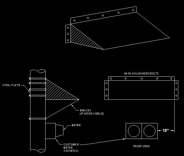
32 609. Meter Ice and Snow Shield A. The meter ice and snow shield should be utilized where meters are not protected by a building overhang and are subject to damage from falling ice and snow, particularly from metal roofs. The building owner is responsible for furnishing and installing the shield. B. The following illustrates typical ice and snow shield configurations.
33
34 Chapter 7. Mobile Home s 701. General A mobile home is defined as: a factory-assembled structure or structures transportable in one or more sections, that is built on a permanent chassis and designed to be used as a dwelling without a permanent foundation where connected to the required utilities, and includes the plumbing, heating, air-conditioning and electric systems contained therein. For the purpose of this manual, unless otherwise indicated, the term "mobile home" includes manufactured homes". Mobile homes, if the axles, wheels, and/or tongue are still in place are considered movable. The code authority or local or state inspector should be consulted for the applicable code sections if the mobile home has been rendered immovable. The Cooperative will consider all manufactured homes to be mobile homes unless the code authority issues an opinion to the contrary Specific Requirements Mobile home service extensions shall comply with the following standards: A. entrance location should be reviewed and accepted by the Cooperative before it is installed. B. The service entrance cannot be mounted on the mobile home and must be within sight of the mobile home, but not more than 30 feet from the mobile home. C. will be 120/240 Volt single-phase. D. The service entrance equipment must be rated 100 Amperes or greater, be waterproof, and mounted at least 2 feet above finished grade level. E. The entrance panel must have at least a 50 ampere 120/240 Volt breaker. F. The Member will install the mobile home service pedestal(s) with the meter pointed toward the driveway or street. G. The Member shall label the pedestal to identify the mobile home being served where it is not obvious. H. The electrical panel shall have branch circuit capability for serving an accessory building, structure, or additional electric equipment. I. The entrance equipment should also have provisions for serving an outdoors 15 or 20 Ampere, 120 Volt GFI outlet. J. The Member cable or cord from the entrance panel shall have an equipment ground, neutral conductor, and two hot conductors.
35 K. Typical mobile home service installation arrangements for single-phase, self-contained, meters are illustrated in the following Figures provided in the back of this Manual: Figure 3-4: Pole Mounted (Secondary Pole) Figure 4-2: Outdoor Installation Figure 4-3: Meter Pedestal Installation Please contact the Cooperative to discuss the arrangement for installations involving more than one meter at a single location.
36 Chapter 8. Farm s 801. Farm Pole Top s Farm pole-top services requiring a minimum 400 Ampere service capacity should follow this general standard. The Member will install a yard pole to support its electrical distribution center. A. All farm use meters must be installed on the yard pole. Member owned equipment is not allowed on Cooperative owned poles. B. The Cooperative will not install additional service drops to any farm building or structure within 50 yards of the Member's distribution center. The Cooperative may provide additional service points beyond the 50 yard minimum separation distance when justified. A separate meter may be installed to another building which is not part of the farm operation. C. The Member shall protect the yard pole from physical damage caused by vehicles and farm operations and maintain its equipment in good operating order. When an existing Cooperative owned yard pole is replaced, it is the Member's responsibility to move its equipment at its own expense. At the Cooperative s option, the existing pole may be given to the Member and the Cooperative may install a new transformer pole. D. The Cooperative will perform all work on its equipment and complete the connection to the Member's service conductors. The Member shall not connect any conductors to the Cooperative s equipment or extend any unmetered wires from the service source. E. The Member will furnish, install and maintain the following: 1. Suitable pole. 2. UL listed pole top transfer switch to interrupt all energized conductors. 3. Meter socket, metering conduit, and metering weather head. 4. ground. F. Optional but desirable Member furnished equipment may include: 1. Guys for Member overhead branch service circuits. 2. Overhead circuits - 4 wire (single phase) or 5 wire (three phase). 3. Yard light. 4. Pole top disconnect operating handle. 5. Standby generator circuit within conduit and weatherproof junction box.

37 G. Member underground circuits extended from the yard pole shall have overcurrent protection. All Member wires on the yard pole shall be installed in conduit. H. The neutral from the pole top switch and all grounding conductors must be bonded together at the yard pole. I. The Member s drip loop conductors shall provide a minimum of 36" leads from the pole top switch. J. The following illustrates typical farmyard pole arrangements.
38 Chapter 9. Special s 901. Cable and Communication Power Supplies Cable and communication power supply service is available at 120/240 Volt, three-wire, single phase. The cable or communication company should contact the Cooperative to ensure that this voltage is available at the desired location. The following requirements apply: A. All installations must conform to all applicable electrical codes and the Cooperative s requirements for clearances, climbing space, and working space. B. Only qualified and authorized representatives for the cable or communication company shall make this installation. Those representatives shall be trained and knowledgeable of clearance requirements and working rules of the NESC and requirements of OSHA. The qualified and authorized representatives shall be trained and competent in: 1. Identifying and distinguishing electric utility system components and exposed live parts. 2. The techniques necessary to determine the nominal voltage of exposed live parts. 3. The minimum safe approach distances corresponding to the voltages to which the qualified representatives will be exposed. C. The cable or communication company shall furnish and install all equipment and materials except the Cooperative s meter. D. The meter socket shall be a minimum of 100 Ampere, ringless, and have manual bypass horns for 120/240 Volt three wire service. E. The service entrance conductors shall be run in non-metallic conduit. The service entrance conductors shall use 600 Volt insulation and shall extend a minimum of 36" beyond the weather head. The Cooperative will make the service connections. F. The service disconnect, power supply unit, meter socket and cable television cable shall be located in the same quadrant on the pole. There shall also be a maximum of 6" between the service entrance conductors and the cable television cable. G. grounding shall comply with the NEC which requires a separate ground, ground lead, and two ground rods for the service. H. The service conductor should be sized for the actual disconnect size utilized. I. Figure 9-1 provided at the back of this Manual illustrates typical cable and communication power supply arrangements.
39 902. Unmetered Decorative Holiday Lighting Unmetered decorative holiday lighting service is available to local governmental units only with Cooperative approval. A master agreement between the Cooperative and the governmental unit is required. The Cooperative reserves the right to deny such attachments. The preferred method is to meter this service. Decorations and festoonery should be removed when billing is terminated. All decorative materials and service equipment must be of approved materials. Decorations shall not be strung between utility poles. Figure 9-2 provided in the back of this Manual illustrates a typical decorative lighting arrangement. The following requirements apply: A. All installations must conform to all applicable electrical codes and the Cooperative s requirements for clearances, climbing space, and working space. B. All work must be done by trained and qualified personnel. C. The service entrance may be 120 Volts or 120/240 Volts, depending on the load requirements and the availability of the supply voltage at the service location. D. equipment should be securely bonded or lagged to the pole. Drilling of holes in poles is not permitted without specific authorization from the Cooperative. E. entrances shall not be installed on poles with transformers, regulation, switching or protective devices, or on corner poles. F. If the entire installation is above communications conductors, the receptacle can be as close as 40" above the communications conductors. G. Non-current carrying metallic parts of decorations operating at less than 150 Volts to ground may be installed no closer than 20" to communications cable or 20" above and 24" below communications conductors. H. An earth ground is not required, provided that a separate grounding conductor is run from the entrance switch enclosure with the service entrance conductors and connected to the secondary neutral by the Cooperative. The green ground wire must connect the switch box, receptacle, and conduit. I. The weatherproof receptacle must have a minimum ground clearance of 10 feet Communication Tower Installation All communication towers are considered to be structures. The Cooperative will provide either one underground service lateral or one overhead service drop to a tower site regardless of the number of tower users.
40 The tower owner shall be responsible for providing metering and service entrance facilities to serve all tenants utilizing the tower facilities. The owner shall contact the Cooperative in advance to plan a suitable metering arrangement and location. Meters will be located outside of the fenced-in tower site. s for cell towers may require the use of special filtering equipment. Consult with the Cooperative before installing. The cost of any additional filtering equipment or other protective device will be borne by the Member.
41 Chapter 10. Primary s Primary Primary service (service at voltages above 600 Volts) is only available upon Cooperative approval. The Member must make application to the Cooperative for the proposed primary service and obtain approval of the location, equipment, and design before starting installation of the service entrance. The Cooperative furnishes, installs, and maintains the primary service and metering equipment in accordance with the Cooperative 's applicable rates and extension rules. The Member furnishes, installs, and maintains all service entrance facilities at the service point other than the metering equipment, regardless of the metering location. Other general requirements for primary metered service include: A. The Member's system beyond the metering point must comply with all applicable NESC, NEC, state, and local electric code requirements. B. entrance equipment located at the point of service shall include: 1. a three-phase, gang-operated load break disconnecting means and over current protection for a thee phase-service, or; 2. a single-phase handle operated disconnect and overcurrent protection for a single-phase service. C. Overcurrent protection shall be provided for all branch lines and transformers. D. Members shall only use grounded wye/grounded wye five-legged or triplex core transformers. Members may only use delta-wye wound transformers with advance approval from the Cooperative. Members may not use three-legged transformers because they can cause substantial overvoltage damage to the Cooperative and Member owned equipment during single phase outages. E. The disconnecting device shall be located to provide a visible open and operating capability to both the member and the Cooperative. F. Clearances and separations must be maintained to the Cooperative s metering equipment. Refer to Chapter 11 for required clearances. G. The sequence of the equipment toward the load shall be meter-switch-fuse with variations approved by the Cooperative. H. Figure 10-1 provided in the back of this Manual illustrates the typical primary service metering schematic and point of service.
42 Chapter 11. Clearances General The NESC, NEC, OSHA and public road authorities specify minimum clearance from electric lines and equipment for safety. Unless otherwise noted, all clearances are from surface-to-surface, and all distance requirements are measured center-to-center Vertical Clearance Requirements for Overhead Conductors The below table provides preferred minimum vertical clearance requirements for overhead secondary and primary conductors. These clearances are under the following conductor temperature and loading conditions, whichever produces the largest final sag: A. 120 degree Fahrenheit, no wind displacement B. Maximum conductor temperature for which the line is to operate, with no wind displacement. C. 32 degree Fahrenheit, ½ radial ice, no wind displacement. Some of these clearances may be reduced if allowed by NESC exceptions. Verify with the Cooperative before applying lesser clearances than those identified in the below table. Preferred Minimum Vertical Clearances to Overhead Conductors Nature of Surface Underneath Conductors Secondary Voltage Conductors (ft) Primary Voltage Conductors (ft) Ground below drip loop of service conductor N/A Streets, alleys, parking lots, driveways, and other areas subject to truck traffic State and county roads Roofs, balconies, and decks Roofs not readily accessible, and outside a 6 radius from service mast, where insulated service wire is 3.0 N/A attached to a service mast. Roofs not readily accessible, and inside a 6 radius from service mast, where insulated service wire is attached to 1.5 N/A a service mast. Signs, chimneys, billboards, antennas, flagpoles, banners, and tanks
43 1103. Horizontal Clearance Requirements for Overhead Conductors The table below provides preferred minimum horizontal clearance requirements for overhead secondary and primary conductors. Some of these clearances may be reduced if allowed by NESC exceptions. Verify with the Cooperative before applying lesser clearances than those identified in the below table. Preferred Horizontal Clearances to Overhead Conductors Nature of Object Horizontal to Conductors Building walls, projections, windows, balconies, fire escapes signs, chimneys and antennas from conductor not attached to the building. Windows, balconies and fire escapes from insulated service wire attached to the building Padmounted Transformer Clearances Secondary Voltage Conductors (ft) Primary Voltage Conductors (ft) N/A The Cooperative shall approve the location of all padmounted transformer. Padmounted transformer locations shall be in accordance with the requirements of NEC, NESC, and National Fire Protection Association (NFPA). In addition, they are to be located far enough from the building overhang so they will not be subject to damage by falling snow and ice. Padmount transformer locations shall be graded for proper drainage and be readily accessible by truck or other means for change-out. Where danger of snow plowing or traffic damage exists, barriers consisting of concrete filled pipe shall be provided for protection. Costs for these barriers shall be borne by the Member. Transformers shall have a minimum separation of 5 feet from natural gas service equipment. A minimum separation of 5 feet shall be maintained between transformers and liquid petroleum facilities on site but not filled on site. If the liquid petroleum facilities are filled on-site, the minimum separation is 10 feet. A 10 foot clearance is required in front of the padmount transformer doors. The following clearances apply to the location of oil-insulated padmount transformers near buildings. A. Non-Combustible Walls (Includes wood framed brick veneered buildings, metal clad steel framed buildings, asbestoscement-board walled metal framed buildings and masonry buildings with a one hour fire rating.)
44 1. Padmount oil-insulated transformers may be located a minimum distance of 2 feet from the roof overhang of a non-combustible walled building if all clearances are maintained from doors, windows, and other building openings. 2. If a combustible first floor overhang exists, a 10-foot distance from the edge of the transformer to the edge of the overhang or its associated roof overhang (combination of vertical and horizontal distance) shall be required in addition to other clearance requirements. 3. Figure 11-1 provided in the back of this Manual illustrates clearances from noncombustible walls. B. Combustible Walls (Includes wood buildings and metal clad building with wood framed construction.) 1. Padmount oil-insulated transformers shall be located a minimum of 10 feet from the roof overhang of combustible walled buildings if all clearances are maintained from doors, windows, and other building openings. 2. If a combustible first floor overhang exists, a 10-foot distance from the edge of the transformer to the edge of the overhang or its associated roof overhang (combination of vertical and horizontal distance) shall be required in addition to other clearance requirements. 3. Figure 11-1 provided in the back of this Manual illustrates clearances from combustible walls. C. Doors, Windows, and Building Openings (Building openings are defined as operable and stationary windows, air intakes and exhaust vents.) 1. Padmount oil-insulated transformers shall not be located within a zone extending 20 feet outward and 10 feet to either side of a building door used primarily as an entrance or exit. Doors to electrical equipment rooms are not considered a primary entrance. 2. Padmount oil-insulated transformers shall not be located within a zone extending 10 feet outward and 10 feet to either side of an opening located at the level of the transformer. If the opening is located above the transformer, the distance from the top of the transformer to the opening shall be a minimum of 10 feet. 3. Figure 11-2 provided in the back of this Manual illustrates clearances from doors, windows, and other openings.
45 D. Fire-Resistant Barrier Walls (Includes reinforced concrete, brick, or concrete block barrier walls with a three-hour fire rating.) 1. If the above clearances cannot be established, a barrier wall may be required. 2. The barrier wall shall have a minimum distance of 2 feet from the padmount oil-insulated transformer. 3. The barrier wall shall extend three feet beyond each side of the padmount oil-insulated transformer. The height of the barrier shall be 3 feet above the top of the padmount oilinsulated transformer. 4. If a combustible first floor overhand exists, the barrier wall must be a minimum distance of 2 feet from the roof overhang. 5. The barrier wall shall extend to a projection line from the corner of the padmount transformer to the furthest corner of a window, door or opening. 6. Figure 11-3 provided in the back of this Manual illustrates clearances with fire-resistance barriers. E. Fire Escapes 1. Padmount oil-insulated transformers shall be located such that a minimum clearance of 20 feet is maintained from a fire escape. 2. This distance can be reduced if a fire resistance barrier is constructed around the padmount oil-filled transformer (side wall and roof). The barrier shall extend a minimum of one foot beyond the transformer in all directions. A clearance of 10 feet is required in front of the padmount transformer doors. Adequate transformer accessibility and ventilation must be provided. 3. Figure 11-4 provided in the back of this Manual illustrates clearances from fire escapes Clearance from Gas Lines The separation in any direction between buried gas and electric and/or communications facilities shall be a minimum of 12 inches. If this clearance cannot be attained, the gas line shall be protected from damage that might result from the proximity of the electric supply or communication directburied system Clearance from Wells Overhead open supply conductors shall not run over wells. The horizontal clearance with conductors at rest shall not be less than ¾ of the vertical clearance to ground. The horizontal clearance shall not be less than 10 feet while the conductors are displaced by wind.
46 Underground supply cable shall have at least a 5 foot separation to the well installation Clearance from Sewer Equipment The horizontal separation between direct-buried cable and other underground sewer equipment should not be less than 12 inches, to permit maintenance access to either facility without damage to the other. The separation in any direction between buried electric conductors and drain fields, alternate fields, or septic tanks should be at least 5 feet if less than 480 Volts and 10 feet if 480 Volts or more Clearance from Material Storage Areas Overhead lines shall not be run over designated material storage areas where material is regularly stored and handled by cranes, dump trucks, elevators, or other types of high machinery, unless the clearance of such lines is adequate to permit the full use of the equipment Clearance from Fuel Storage Tanks Electric lines shall not be run over above-ground flammable liquid or liquefied petroleum gas (LPG) storage tanks. A horizontal clearance of not less than 8 feet is required for services and secondary cables and 15 feet for all other conductors. LPG tanks with a capacity of 1,000 gallons or less or tanks enclosed in a building or fully covered by a roof or canopy capable of preventing a falling overhead supply conductor from directly contacting the tank are exempt from this requirement. A horizontal clearance of not less than 20 feet is required from gasoline dispensers, not less than 10 feet is required from tank fill pipes, and not less than 3 feet is required from tank vent pipes. Underground supply cables shall not come within 10 feet of above ground or below ground fuel storage tanks. Underground cables shall not go under fuel storage tanks Clearance from Antennas Outdoor antennas and supporting structures attached to buildings shall have a horizontal clearance from utility electric lines greater than the total height of the antenna and supporting structure. cables of 150 Volts or less to ground shall have a minimum clearance of 3 feet 6 inches from the antenna and supporting structure except a minimum clearance of 2 feet is permitted from the service conductor drip loop Requirements for Conductors under Structures Any electric facilities proposed to pass under structures must be approved by the Cooperative. All such approved facilities shall be installed in conduit.
47 1112. Clearance from Swimming Pools Cooperative owned supply cables operating at 750 Volts or less shall have at least 22.5 feet of clearance in any direction from the pool s water level, edge, base of diving platform, or anchored raft. The clearance shall be at least 14.5 feet in any direction from the diving platform, tower, water slide, or other fixed, pool-related structures Clearance Envelope for Grain Bins NESC rule 234F specifies the minimum clearances of wires, conductors, cables, and rigid live parts from grain bins. A. The horizontal clearance requirement on the loading side of a grain bin filled with portable auger/elevator systems is increased to the sum of the grain bin height plus 18 feet. A clearance of not less than 18 feet is required in all directions from probe ports in the grain bin roof to all wires, conductors and cables. Figure 11-5 provided in the back of this Manual illustrates clearances from grain bins filled by portable augers, conveyors, or elevators. B. A vertical clearance of at least 13.5 feet and a horizontal clearance of at least 15 feet shall be maintained between grain bins with permanently installed elevator systems and open supply conductors operating from 0-22,000 Volts. The distances are measured from the outermost and uppermost parts of the grain bin/elevator structure. Figure 11-6 provided in the back of this Manual illustrates clearances from grain bins filled with permanently installed augers, conveyors, or elevators. Consult with the Cooperative prior to siting new bin installations. If NESC clearance violations are found, the cost for moving Cooperative facilities shall be borne by the Member.
48 Chapter 12. On-Site Generation (Distributed Energy Resources) General Member owned emergency, standby, and parallel generation systems are also referred to distributed generation (DG) and distributed energy resources (DER). These systems are subject to the Cooperative s distributed generation policy in addition to federal, state, and local rules. The Cooperative s rules include: A. The Member shall inform the Cooperative of plans to install and connect any generating equipment to its electrical system. B. The generating equipment shall not introduce potentially dangerous situations to the Cooperative s personnel or the public. C. Generation that can operate either momentarily or continuously in parallel with the Cooperative s facilities shall incorporate protective devices (relays, circuit breakers, etc.) and metering equipment as specified by the Cooperative s specific interconnection agreement with the Member. D. The interconnection of a DG facility to an electric service must be to the same electric service that is common to the electrical system of a building or premises where the DG facility is physically installed. Conversely a DG facility CANNOT be interconnected with an electric service that is not common to the electric system of a building or premises where the DG facility is physically installed Standby Generators Standby generating equipment shall be connected to the Member side of the meter with properly sized double-throw switches or transfer switches so that the Member s generating equipment cannot reverse energize the Cooperative s supply lines Parallel Generation Proposed parallel generation installations require that the Member enter into a contractual agreement with the Cooperative. The Member should consult the Cooperative for the rules and requirements that are specific to the proposed arrangement. Figure 12-1 in the back of this Manual provides drawings intended to aid the interconnection application process Interconnection Application Prior to the interconnection and energization of any member-owned generation with the Cooperative s system, an application must first be submitted to the Cooperative. The specific location and the effect of the proposed generation on the distribution system must first be evaluated. Technical drawings and operating characteristics must also be reviewed. The drawings provided in Figure 12-1 may serve as a template for rating specification but may not be used in
49 lieu of detailed engineering schematics for interconnection review. Additional application information is beyond the scope of this document Modifications to Cooperatives System Any modification to the Cooperative s distribution system determined to be required to accommodate member-owned generation will be at the Member s expense Primary Metering Primary metered Members wishing to install a distributed energy resource must abide by the Cooperative s existing primary meter standards within this manual. Please contact the Cooperative for further details and requirements Labeling Requirements The Member must provide all labels in accordance with the appropriate edition of the NFPA 70 (National Electric Code). At a minimum, the Member shall install labels at the meter socket and distributed energy resource interconnection switch, indicating the following information: At Meter: DUAL POWER SOURCE DER CIRCUIT Operating Voltage: Maximum Current: Maximum Power: At DER Disconnect Switch: INTERCONNECTION DISCONNECT SWITCH Labeling material must be made of a suitable material for permanent installation. Material shall be rigid, engraved plastic, brass, or aluminum, and must consist of ¼ block lettering, minimum. A permanent plaque identifying all disconnecting means at the facility must be installed at each service equipment location and at each system disconnect for any power source that may be interconnected.
50 Chapter 13. Equipment Requirements to Maintain Power Quality Supplemental to the requirements identified in this Manual, Member installations, Member owned equipment, power quality parameters, and other operating standards must also comply with the Cooperative s Engineering Manual Motors and Associated Equipment The Member is responsible for providing protection, uninterruptible power supplies, or other accessories needed to prevent undesirable operation of other Members equipment or the Cooperative s sensitive equipment created by voltage or current waveform distortion within the thresholds established in IEEE Standard 519. The Member is responsible for ensuring that their equipment is protected from excessive currents which may result from overvoltage, undervoltage, single-phase operation of three-phase equipment, phase reversal, or other abnormal conditions by means of Member installed fuses, thermal cutouts, overload relays, or other relays and devices designed to protect the individual s equipment. The Member is also responsible for notifying the Cooperative in advance of planned load increases as well as planned service modifications or upgrades. Advance notification will permit the Cooperative to evaluate the adequacy of the existing facilities to serve the load increase and/or service capacity of the facilities, if necessary. Prior to selecting and purchasing motor equipment, it is the Member s responsibility to consult the Cooperative to determine the availability of specific service voltages and capacity limitations at any location. Member installed motors shall not cause problematic momentary voltage fluctuations on the Cooperative s electric distribution system. The below table lists motor sizes that may be installed if the starting current does not exceed the limits illustrated under the various services and starting types listed. Multiple motors starting simultaneously shall be classified as one motor. Type Motor Type Maximum HP* Source Voltage at Starter Reduced Voltage/ Frequency Starter Type Maximum Locked Rotor Amps Maximum kva Inrush 1-Phase 1-Phase 5.0 hp 120 None (Across the Line) Phase 1-Phase 7.5 hp 240 None (Across the Line) Phase 1-Phase 10 hp 240/480 Autotransformer & Solid State 200/ Phase 1-Phase 15 hp 240/480 Variable Frequency Drive 200/ Phase 3-Phase 10 hp 240/480 Rotary Converter, 20 kva 200/ Phase 3-Phase 40 hp ** 120/208 Across the Line ** Phase 3-Phase 40 hp ** 277/480 Across the Line ** * Based on NEC locked rotor indicating code letters A-G. ** As with single-phase motors, the allowable size of these 3-phase motors can be increased with use of reduced voltage/frequency starters or soft-start motors.
51 Upon request of the Member, the Cooperative will evaluate services for motor starting conditions that exceed the maximum allowable kva motor inrush identified in the previous table. kva motor starting inrush larger than what is stated in table may be permitted at locations where the Cooperative facilities are adequate. Single-phase to three-phase rotary phase converters may be connected only if the inrush current of the rotary converter itself does not exceed that for single-phase motor kva inrush listed in the previous table. Rotary phase converters typically require a kva rating twice that of the largest three-phase motor they supply. After the rotary converter attains full speed, the starting of the motor fed from the phase converter must not cause current on the source side of the converter to be greater than that allowed for the converter on its source side. When reduced voltage starters are applied to motors to minimize flicker, the motor starting torque is also reduced. The Member is responsible for verifying that the reduced voltage or lower frequency applied to the motor will allow starting for all required load conditions. Motors subject to frequent starts and inrush currents, such as elevators and hoist and rock crushers, when connected to the secondary distribution system, shall have their starting current limited to 100 amperes at volts basis. The Member is responsible for complying with IEEE Standard 141 and ANSI C84.1 Electric Power Systems and Equipment with respect to power quality and voltage regulation, and any other applicable industry standards. Voltage fluctuations at the point of common connection in the sub-transient and transient (near instantaneous) realm, due to Member s controlling of motor(s), must not adversely affect sensitive electronic equipment installed at this or other Member locations, or the Cooperative s equipment. The standard voltage tolerances for operating electronic equipment represented by the Information Technology Information Council (ITI) curve shall not be infringed upon. The ITI curve is an update of the CBEMA curve. Motors used to drive equipment that creates an extreme variation in electric load over a short period of time in a continuous manner, such as saw mills, electrical welding machines, x-ray machines, arc furnaces, etc., are subject to engineering review before they will be allowed to be connected to the Members s distribution system. Motors that create a voltage rise when switched off, which cause the voltage flicker to exceed the values stated herein are not allowed. Voltage flicker limits that are exceeded when motors are switched off require mitigation methods typically found in a solid-state starter or a variable speed drive where the ramp down feature gradually reduces the load so as not to create an excessive rise in voltage flicker above the stated limits herein. For larger motors that do not meet the limitations stated herein, the locked rotor current limits, or the maximum number of starts per hour, preapproval in writing of the installation will be required by the Member after an engineering evaluation and before connection is permitted. The Member s
52 design criteria is intended to limit the primary line voltage flicker to 3% or less, and limit the secondary voltage flicker to 5% for the Member. Approval by the Cooperative of a motor on the basis of analyzing the effect of voltage flicker does not necessarily imply that the motor meets other requirements, such as harmonics Electric Water Heating All electric water heaters shall be connected in accordance with local and state plumbing codes. Water heaters shall be equipped with resistive heating elements which may be connected to 120 Volts or 240 Volts. If connected at 120 Volts, the maximum heating element is 1,650 Watts. If connected at 240 Volts, the maximum heating element size shall be 5,500 Watts. Water heaters having two or more elements shall have the heating elements interlocked to limit the connected load to the above limits. Instant recovery water heaters with wattages above 5,500 require the permission of the Cooperative to connect. If allowed by the Cooperative, the Member may be responsible for the cost of transformer and secondary conductor upgrades required to accommodate the water heater Electric Space Heating Electric space heating equipment designed to operate at 120 Volts shall be limited to 1,650 Watts controlled by a single thermostat. Electric space heating equipment designed to operate at 208 Volts and greater shall be limited to 6,000 Watts controlled by a single thermostat. Equipment exceeding 6,000 Watts shall be energized in stages not exceeding 6,000 Watts per stage and at time intervals between stages of at least 3 seconds Electric Welders and Furnaces Electric welders and furnaces may not cause interference or impairment to the service of other Members. The Cooperative requests notification before a welder or furnace is connected to ensure that its facilities have adequate capacity and service to other Members is not impaired Harmonics and High Frequency Equipment The Cooperative will provide electric service to the Member in compliance with the latest version of IEEE Standard 519. In return, the Member is responsible to comply with the same Standard in respect to current harmonic distortion. Member owned utilization and production equipment causing high frequency current or harmonics must comply with IEEE Standard 519. All wiring carrying high-frequency current shall be located as remotely as possible from the meter and wiring of the building. The Cooperative may require the Member to install an isolation transformer or filters to protect the meter and metering devices, and limit service interference to adjacent Members.
53 1306. Air Conditioners Air conditioners for use at 120 Volt single phase are limited to a maximum locked rotor current of 50 amps and a maximum of 4 starts per hour. Air conditioners and heat pumps for use at 240 Volts or 208 Volts single phase are limited to locked rotor currents as follows and a maximum of 4 starts per hour. BTU per Hour Rating Total Locked Rotor Current (BTUH) Limitation Up to 20, amps 20,000 to 36, amps plus 3 amps per 1000 BTUH in excess of 20,000 BTUH Over 36,000 Consult the Cooperative Note: 12,000 BTU = 1 Ton Please refer to the table in Section 1301 for starting limitations on three-phase air conditioners Phase Balance Equipment The Member shall balance electrical loads on the service entrance. Each phase conductor shall carry at least 25% of the total KVA at maximum load conditions Power Factor Correction The Member may be required to limit the size of static power factor correction installations or to maintain effective control of the capacitors in order to prevent excessively high voltage at the service location. Member owned power factor corrective equipment shall be installed on the load side of the service disconnecting device and metering Electrical Equipment Protection and Safety The Member shall provide protection against low voltage or phase loss where low voltage, phase loss, or unexpected restarting could cause damage to the Member s equipment or result in personal injury. The Member shall install control apparatus equipped with reverse-phase relays on all poly-phase motor installations for elevators, hoists, cranes, and any manufacturing processes where accidental reversal of rotation may cause injury to persons or damage to equipment or work in progress.
54 Jo-Carroll Energy Inc. (NFP) Electric s Min Max Meter Form Meter Connection Min Breaker kaic Rating # of Conduits Conduit Size Min Bend Radius Phase Wire Voltage (Volts) (Amps) (Amps) (ka) (in) (steel) (pvc) 100 (OH Only) 150 (OH Only) Min Bend Radius 2S 10, " 18" Self-Contained S 22, " 24" Single Three-Wire 120/ S CTs required 42, " 30" Three- Network 120/ S Self-Contained 22, " 18" S Self-Contained 22, " 30" , " 30" , " 30" >800 1,200 9S CTs required 65, " 30" Three Four-Wye 120/208 > 1,200 1,600 42, " 36" > 1,600 2,500 65, " 36" , " 30" 16S Self-Contained > , " 30" , " 30" > 700 1,100 9S CTs Required 22, " 36" 277/480 >1100 3,000 65, " 36" Notes: 1. Location, Lateral Length and Lateral Route shall be determined and/or approved by Jo-Carroll Energy, Inc. (NFP) 2. Conduits shall be Schedule 40 PVC below grade and Schedule 80 PVC above grade. NO DRAIN TILE ALLOWED amp service with self-contained meter current connection shall not exceed 320 amps of continuous current. Electrical Summary Guide (Figure 1-1) DATE: DRAWN BY: APPROVED BY: SCALE: 08/21/2018 KPI ESS N.T.S.
55 2 Notes: 1 Temporary overhead service drop not to exceed 100 ft. Overhead service drop conductor and wire holder provided and installed by Cooperative. 2 The service attachment shall be installed at a height that maintains NEC and NESC clearance requirements for service drop conductors at final worst case sag and not be less than: (a) Residential driveways: A minimum of 16.5' in span clearance is required over residential driveways. (b) Roads, non-residential driveways, etc., subject to truck traffic: A minimum of 20' in span clearance is required over roads, streets, non-residential driveways, parking lots and other areas subject to truck traffic. (c) Pedestrian areas: A minimum of 12.5' in-span clearance is required for service drop conductors over spaces and ways subject to pedestrians '-0" (min.) copper clad ground rods furnished and installed by Member. 12 Grounding electrode conductor, #4 copper minimum, provided and installed by Member in accordance with NEC and local regulations. 13 Treated lumber field built structure provided and installed by Member. Installation must meet Cooperative's requirements. (a) Nail 2"x6" timbers full length, minimum size 16D (3-1/2") nails. (b) If service drop must be attached at a point higher than 12' in order to obtain required clearance to ground, use two 2" x 4" x 8'-0" braces nailed together for increased stiffness. (c) A tool shed (if available) or other type of fixed support may be used as a temporary service drop attachment if such support provides equal strength and proper clearances 3 3 Point of Demarcation (service point) between Cooperative and Member. Member service conductors shall extend beyond weatherhead a minimum of 36". 6" min 18" max 4 4 drop wire holder provided and installed by the Member at a minimum height of 10'-0" above final grade '-0" Approx. 5 mast provided, securely installed and maintained by Member. Conduit straps as required by conduit size. 6 Conductors in conduit to be furnished, installed and maintained by the Member. Minimum conductor size to be according to the NEC. 2 7 Meter base furnished and installed by the Member in a plumb position at a location to be designated by Cooperative at 5'-0" above final grade to center of meter. 8 Meter provided and installed by Cooperative. 9 Fuse/breaker box and switch (weatherproof or covered) provided and installed by Member on a board base on structure. 10 Member to provide and install receptacle. Mount outlets down. Ground Fault Interrupter (GFI) as required by NEC and the local governing authority. 6" Grade '-6" Max. 7'-0" Approx. 5'-0" M 10 5 One 6"x6" (nom.) or three 2"x6" (nom.) treated timbers nailed back to back (Note 12) Use 20D (4") min. nails at this point Use 16D (3-1/2") min. nails 2"x4"x8'-0" brace (Note 12) 1"x6" common board for cross bracing. (Note 12) Use 10D (3") min. nails (either end) 1'-6" 6" 13 Top View 2"x4" stake nailed with 10D (3") nails minimum to both 8 ft. braces. (Note 12) 2nd 2x4 if req'd 5'-0" Approx. 6'-0" Min. 1'-6" Min. 3'-9" Min. 11 # - Designates Cooperative provided Temporary Temporary Overhead (Figure 2-1) 06/23/2017 KPI ESS N.T.S. DATE: DRAWN BY: APPROVED BY: SCALE: # - Designates Member provided

56 1 10 Notes: 1 Temporary service lateral not to exceed 100 ft. 2 Conduit on pole provided and installed by Cooperative. 3 Member to trench to pole or transformer. 4 Right of way strip for trenching must be graded to within 4" of final grade prior to trenching. 5 Bottom of trench must be level and free of loose or projecting stones and debris. Backfill shall be sand or screened earth for the first 6" above directly buried cable. 6 Under driveway, walkway and patio crossings Member to provide 2" minimum diameter galvanized rigid steel conduit or schedule 80 or better PVC listed for underground use. 7 Underground secondary cables to be furnished, installed and maintained by the Cooperative under the conditions of the existing underground service policy. 8 Member to provide insulated bushings required on all conduit ends degree conduit sweep required at 36" trench depth. 10 Depth must be maintained to final grade. 11 If concrete is to be poured around conduit Member shall use sleeve to provide clearance between conduit and concrete. Sleeve to be 1 1/4" larger than conduit O.D. 12 Secondary cable conduit provided by Member. 13 Slip joint with a minimum of 12" travel supplied by Member. 14 Meter base furnished and installed by the Member in a plumb position at a location to be designated by Cooperative at 5'-0" above final grade to center of meter. 15 Meter provided and installed by Cooperative. 16 Fuse/breaker box and switch (weatherproof or covered) provided and installed by Member on board base on post. 17 Member to provide and install receptacle. Mount outlets down. Ground Fault Interrupter (GFI) as required by NEC and the local governing authority. 18 Conduit to be furnished, securely installed and maintained by Member. Conduit straps as required by conduit size. 19 Conductors in conduit to be furnished, installed and maintained by the Member. Minimum conductor size to be according to the NEC. 20 8'-0" (min.) copper clad ground rods furnished and installed by Member Grounding electrode conductor, #4 copper minimum, provided and installed by Member in accordance with NEC and local regulations M "x4" treated lumber post provided and installed by Member. Installation must meet Cooperative's requirements. 6" " dia. post hole 13 5'-0" above grade Walkway 3 Roadway or Driveway 4 2 Grade Pole Padmount Transformer 36" 36" Min Install warning tape '-0' Minimum ' Max. 6 7 # - Designates Cooperative provided Temporary Temporary Underground (Figure 2-2) 06/23/2017 KPI ESS N.T.S. DATE: DRAWN BY: APPROVED BY: SCALE: # - Designates Member provided
57 1 10 Notes: 1 Temporary service lateral not to exceed 100 ft. 2 Conduit on pole provided and installed by Cooperative. 3 Member to trench to pole or transformer. 4 Right of way strip for trenching must be graded to within 4" of final grade prior to trenching. 5 Bottom of trench must be level and free of loose or projecting stones and debris. Backfill shall be sand or screened earth for the first 6" above directly buried cable. 6 Under driveway, walkway and patio crossings Member to provide 2" minimum diameter galvanized rigid steel conduit or schedule 80 or better PVC listed for underground use. 7 Underground secondary cables to be furnished, installed and maintained by the Cooperative under the conditions of the existing underground service policy. 8 Member to provide insulated bushings required on all conduit ends degree conduit sweep required at 36" trench depth. 10 Depth must be maintained to final grade. 11 If concrete is to be poured around conduit Member shall use sleeve to provide clearance between conduit and concrete. Sleeve to be 1 1/4" larger than conduit O.D. 12 Secondary cable conduit provided by Member. 13 Slip joint with a minimum of 12" travel supplied by Member. 14 Meter base furnished and installed by the Member in a plumb position at a location to be designated by Cooperative at 5'-0" above final grade to center of meter. 15 Meter provided and installed by Cooperative. 16 Fuse/breaker box and switch (weatherproof or covered) provided and installed by Member on field built structure. 17 Member to provide and install receptacle. Mount outlets down. Ground Fault Interrupter (GFI) as required by NEC and the local governing authority. 18 Conduit to be furnished, securely installed and maintained by Member. Conduit straps as required by conduit size. 19 Conductors in conduit to be furnished, installed and maintained by the Member. Minimum conductor size to be according to the NEC. 20 8'-0" (min.) copper clad ground rods furnished and installed by Member Grounding electrode conductor, #4 copper minimum, provided and installed by Member in accordance with NEC and local regulations. M Treated lumber field built structure provided and installed by Member. Installation must meet Cooperative's requirements '-0" above grade 2 6" " dia. post hole Walkway 3 Roadway or Driveway 4 Grade Pole Padmount Transformer 36" 36" Min Install warning tape 20 6'-0' Minimum ' Max. 6 7 # - Designates Cooperative provided Temporary Temporary Underground (Figure 2-3) 06/23/2017 KPI ESS N.T.S. DATE: DRAWN BY: APPROVED BY: SCALE: # - Designates Member provided
58 Openable Window 36" 36" 36" 5'-0" 36" Gas 36" 36" = Areas to avoid with meter and service mast Overhead Location Clearance requirements (Figure 3-1) DATE: DRAWN BY: APPROVED BY: SCALE: 06/23/2017 KPI ESS N.T.S.
 Joist 2\" RGS conduit Pipe clamp 9 Rafter 10 Two hole, 2\" pipe clamp (1 1 4\" x 1 4\" stock) bolted to building plate.")
59 "x4" plate Siding Roof Rafters 3 3" 5 10 "X" To Cooperative pole 36" Max " x 5" mach. bolts, round washer and flat washer (countersink bolt into plate if necessary) Joist 2" RGS conduit Pipe clamp 9 Rafter 10 Two hole, 2" pipe clamp (1 1 4" x 1 4" stock) bolted to building plate. Ream holes in clamp for 1 2 " bolt. Refer to Detail "A". 16" 16" DETAIL "A" Method of attaching 2" conduit to building plate 10 Wood frame building: - use 5 16" x 2" wood screw (galv.) Masonry building: - use 5 16" x 2" expansion bolts or expansion shields Tile or cinder block building: - use 5 16" x 4" toggle bolts (galv.) 7 House siding Wireholder with pipe mounting bracket provided and installed by Member. Only Cooperative service conductors are allowed to contact the service mast. Minimum allowable distance between roof and service attachment is 18" if dimension "X" is 4'-0" or less. Maximum height without guying is 36". 10 Two hole, 2" pipe clamp (1 1 4" x 1 4" stock) with 3/8" dia. holes (galv.) 5'-0" above grade Point of Demarcation (service point) between Cooperative & Member. 5 Rigid steel conduit service mast and weather head provided, securely installed and maintained by Member. Location designated by Cooperative. mast to be used as service drop attachment point only where it is impossible to attach wire holders to the building wall and maintain proper clearance. To electric panel 6" Final Grade 6 Conductors in conduit to be furnished, installed and maintained by the Member. Minimum conductor size to be according to the NEC. Maximum conductor fill in 2" RGS conduit is 3-#4/0 conductors or service entrance cable equivalent. entrance conductors shall extend beyond weather head a minimum of 36". 11 6'-0" Minimum 7 Meter base furnished and installed by the Member in a plumb position at a location to be designated by Cooperative at 5'-0" above final grade to center of meter. 8 Meter provided and installed by Cooperative. Notes: 9 Member to install service mast through a 2-3/8" dia. hole in a 2"x12" min. block solidly mounted between rafters using 3/8"x4" wood screws, four on each side. 2 1 Overhead service drop conductors provided and installed by Cooperative. 2 The service attachment shall be installed at a height that maintains the following clearances for service drop conductors at final worst case sag. (a) Residential driveways: A minimum of 16.5' in span clearance is required over residential driveways. (b) Roads, non-residential driveways, etc., subject to truck traffic: A minimum of 20' in span clearance is required over roads, streets, non-residential driveways, parking lots and other areas subject to truck traffic. (c) Pedestrian areas: A minimum of 12.5' in-span clearance is required for service drop conductors over spaces and ways subject to pedestrians. 10 Member to provide and install roof flashing with waterproof seal around conduit, building plate attachment and building attachments. Conduit straps as noted on drawing. 11 8'-0" (min.) copper clad ground rod provided and installed by Member in accordance with NEC and local regulations. 12 Grounding electrode conductor, #4 copper minimum, provided and installed by Member in accordance with NEC and local regulations. Ground wire shall not be connected to meter socket. # - Designates Cooperative provided Overhead Through the Roof Installations (Figure 3-2) 06/23/2017 KPI ESS N.T.S. DATE: DRAWN BY: APPROVED BY: SCALE: # - Designates Member provided
60 6 5 2 drop attachment 1 To Cooperative pole To electric panel M '-0" above grade 10'-0" Min The service attachment shall be installed at a height that maintains NEC and NESC clearance requirements for service drop conductors at final worst case sag and not be less than: (a) Residential driveways: A minimum of 16.5' in span clearance is required over residential driveways. (b) Roads, non-residential driveways, etc., subject to truck traffic: A minimum of 20' in span clearance is required over roads, streets, non-residential driveways, parking lots and other areas subject to truck traffic. (c) Pedestrian areas: A minimum of 12.5' in-span clearance is required for service drop conductors over spaces and ways subject to pedestrians. 4 Point of Demarcation (service point) between Cooperative & Member. 5 Rigid steel or Sched. 80 PVC conduit service mast and weather head provided, securely installed and maintained by Member. Location designated by Cooperative. 6" 11 Final Grade 6 Conductors in conduit to be furnished, installed and maintained by the Member. Minimum conductor size to be according to the NEC. Maximum conductor fill in 2" RGS conduit is 3-#4/0 conductors or service entrance cable equivalent. entrance conductors shall extend beyond weather head a minimum of 36". Notes: 10 6'-0" Minimum 1 Overhead service drop conductors provided and installed by Cooperative. drop tension to be limited to 500 lbs. under loaded conditions. 2 drop wire holder provided and installed by the Member at a minimum height of 10'-0" above final grade. 7 Member to provide and install conduit straps as required by conduit size. 8 Meter base furnished and installed by the Member in a plumb position at a location to be designated by Cooperative at 5'-0" above final grade to center of meter. 9 Meter provided and installed by Cooperative. 10 8'-0" (min.) copper clad ground rods provided and installed by Member in accordance with NEC and local regulations. 11 Grounding electrode conductor, #4 copper minimum, provided and installed by Member in accordance with NEC and local regulations. Ground wire shall not be connected to meter socket. Overhead Wall Mount Installations (Figure 3-3) 06/23/2017 KPI ESS N.T.S. DATE: DRAWN BY: APPROVED BY: SCALE: # - Designates Cooperative provided # - Designates Member provided

61 Notes: 1 Pole provided and installed by Member. Consult the Cooperative for appropriate class, setting depth and pole length. Location designated by Cooperative. 2 Overhead service drop conductors provided and installed by Cooperative. 6" min 18" max To Cooperative pole 3 drop wire holder provided and installed by the Member at a minimum height of 10'-0" above final grade The service attachment shall be installed at a height that maintains NEC and NESC clearance requirements for service drop conductors at final worst case sag and not less than: (a) Residential driveways: A minimum of 16.5' in span clearance is required over residential driveways. (b) Roads, non-residential driveways, etc., subject to truck traffic: A minimum of 20' in span clearance is required over roads, streets, non-residential driveways, parking lots and other areas subject to truck traffic. (c) Pedestrian areas: A minimum of 12.5' in span clearance is required for service drop conductors over spaces and ways subject to pedestrians. 5 Point of Demarcation (service point) between Cooperative and Member '-0" Min Rigid steel or Sched. 80 PVC conduit service mast and weather head provided, securely installed and maintained by Member. 7 Conductors in conduit to be furnished, installed and maintained by the Member. Minimum conductor size to be according to the NEC. Maximum conductor fill in 2" RGS conduit is 3-#4/0 conductors or service entrance cable equivalent. entrance conductors shall extend beyond weather head a minimum of 36". 8 Member to provide and install conduit straps as required by conduit size. 9 Meter base furnished and installed by the Member in a plumb position at 5'-0" above final grade to center of meter. 10 Meter provided and installed by Cooperative. 11 disconnect provided and installed by Member '-0" (min.) copper clad ground rods provided and installed by Member in accordance with NEC and local regulations M 13 Grounding electrode conductor, #4 copper minimum, provided and installed by Member in accordance with NEC and local regulations. Ground wire shall not be connected to meter socket. 13 5'-0" above grade 14 Member to provide and install down-guy and anchoring when required. Consult Cooperative to obtain service drop tension and direction so adequate and effective guying can be installed. Final Grade 6" 12 Minimum 6'-0" 6'-0" Minimum Overhead Pole Mounted (Secondary Pole) (Figure 3-4) 06/23/2017 KPI ESS N.T.S. DATE: DRAWN BY: APPROVED BY: SCALE: # - Designates Cooperative provided # - Designates Member provided
62 Notes: 9 1 Conduit on pole provided and installed by Cooperative. 2 Member to trench to pole or transformer. 3 Right of way strip for trenching must be graded to within 6" of final grade prior to trenching. 4 Bottom of trench must be level and free of loose or projecting stones and debris. Backfill shall be sand, 1/4" crushed limestone or screened earth for the first 6" above directly buried cable. 5 Under driveway, walkway and patio crossings Member to provide 2" minimum diameter galvanized rigid steel conduit or schedule 80 or better PVC listed for underground use. 6 Underground secondary cables to be furnished, installed and maintained by the Cooperative under the conditions of the existing underground service policy. 7 Member to provide bell ends required on all conduit ends degree conduit sweep required at 36" trench depth. 9 Depth must be maintained to final grade. 10 If concrete is to be poured around conduit, Member shall use sleeve to provide clearance between conduit and concrete. Sleeve to be 1 1/4" larger than conduit O.D. 11 Secondary cable conduit provided by Member. 12 Slip joint with a minimum of 12" travel supplied by Member. 13 Meter base furnished and installed by the Member in a plumb position at a location to be designated by Cooperative at 5'-0" above final grade to center of meter. 14 Meter provided and installed by Cooperative. 15 Conduit to be furnished, securely installed and maintained by Member. Conduit straps as required by conduit size. 16 Conductors in conduit to be furnished, installed and maintained by the Member. Minimum conductor size to be according to the NEC. 17 Grounding electrode conductor, #4 copper minimum, provided and installed by Member in accordance with NEC and local regulations. 18 8'-0" (min.) copper clad ground rods furnished and installed by Member M " 17 5'-0" above grade 10 Walkway 2 Roadway or Driveway 3 1 Grade Pole Padmount Transformer 8 36" Min. 9 9 Install warning tape 18 6'-0' Minimum # - Designates Cooperative provided Underground Wall Mount Installation (Figure 4-1) 09/21/2017 KPI ESS N.T.S. DATE: DRAWN BY: APPROVED BY: SCALE: # - Designates Member provided

63 Notes: 9 1 Conduit on pole provided and installed by Cooperative. 2 Member to trench to pole or transformer. 3 Right of way strip for trenching must be graded to within 6" of final grade prior to trenching. 4 Bottom of trench must be level and free of loose or projecting stones and debris. Backfill shall be sand, 1/4" crushed limestone or screened earth for the first 6" above directly buried cable. 5 Under driveway, walkway and patio crossings Member to provide 2" minimum diameter galvanized rigid steel conduit or schedule 80 or better PVC listed for underground use. 6 Underground secondary cables to be furnished, installed and maintained by the Cooperative under the conditions of the existing underground service policy. 7 Member to provide bell ends required on all conduit ends degree conduit sweep required at 36" trench depth. 9 Depth must be maintained to final grade. 10 If concrete is to be poured around conduit, Member shall use sleeve to provide clearance between conduit and concrete. Sleeve to be 1 1/4" larger than conduit O.D. 11 Conduit to be furnished, securely installed and maintained by Member. Conduit straps as required by conduit size. 12 Slip joint with a minimum of 12" travel supplied by Member. 13 Meter base furnished and installed by the Member in a plumb position at a location to be designated by Cooperative at 5'-0" above final grade to center of meter. 14 Meter provided and installed by Cooperative. 15 Fuse/breaker box and switch (weatherproof or covered) provided and installed by Member on field built structure. 16 Conductors in conduit to be furnished, installed and maintained by the Member. Minimum conductor size to be according to the NEC. 17 Grounding electrode conductor, #4 copper minimum, provided and installed by Member in accordance with NEC and local regulations. 18 8'-0" (min.) copper clad ground rods furnished and installed by Member Treated lumber field built structure provided and installed by Member. Installation must meet Cooperative's requirements. 14 M '-0" above grade 1 6" " dia. post hole Walkway 2 Roadway or Driveway 3 Grade Pole Padmount Transformer 36" 36" Min. 9 9 Install warning tape To Member '-0' Minimum Underground Outdoor Installation (Figure 4-2) 09/21/2017 KPI ESS N.T.S. DATE: DRAWN BY: APPROVED BY: SCALE: # - Designates Cooperative provided # - Designates Member provided


64 Notes: 1 Conduit on pole provided and installed by Cooperative. 2 Member to trench to pole or transformer. 3 Right of way strip for trenching must be graded to within 6" of final grade prior to trenching. 4 Bottom of trench must be level and free of loose or projecting stones and debris. Backfill shall be sand, 1/4" crushed limestone or screened earth for the first 6" above directly buried cable. 5 Under driveway, walkway and patio crossings Member to provide 2" minimum diameter galvanized rigid steel conduit or schedule 80 or better PVC listed for underground use. 6 Underground secondary cables to be furnished, installed and maintained by the Cooperative under the conditions of the existing underground service policy. 10 If concrete is to be poured around pedestal, Member shall use sleeve to provide clearance between pedestal and concrete. 11 Secondary cable conduit provided by Member. 12 Meter pedestal furnished and installed by the Member in a plumb position at a location to be designated by Cooperative. 13 Meter provided and installed by Cooperative. 14 Grounding electrode conductor, #4 copper minimum, provided and installed by Member in accordance with NEC and local regulations. 15 8'-0" (min.) copper clad ground rods furnished and installed by Member. 7 Member to provide insulated bushings required on all conduit ends degree conduit sweep required at 36" trench depth. 9 9 Depth must be maintained to final grade M 6" 14 36" Min. above grade 10 Walkway 2 Roadway or Driveway 3 1 Grade Pole Padmount Transformer 18" Min " Min. 9 9 Install warning tape 15 6'-0' Minimum # - Designates Cooperative provided Underground Meter Pedestal Installation (Figure 4-3) 09/21/2017 KPI ESS N.T.S. DATE: DRAWN BY: APPROVED BY: SCALE: # - Designates Member provided
65 B B A This area to be backfilled with well tamped gravel. See Note 5 8" Typ. Window in pad A C 39" min. E Chamfer all around 30" D Conduits 13" Primary Secondary Alternate locations Foundation Wall Top View Alternate locations Foundation Pad Dimensions Top View See Note 4 4" Pad (shown for ref.) 4" 2" 3" clear all around See Note 5 2" 12" 36" 2" Typ. 18" Min. 12" 15" Alternate locations 2" See Note 5 2" 4" 6" Foundation Wall Front View 12" 12" Window in pad 27" 30" 27" Partial Foundation Wall - Alternate Top View 27" Pad (shown for ref.) Foundation Wall - Alternate Front View 14" 4" 36" Alternate locations Pad I II XFMR kva Primary Secondary Foundation Pad Reinforcing Top View A Dimensions in Inches C D E B Thickness 6 8 Notes: 1. The Member shall install, own and maintain a concrete pad whenever the underground service requires a 3ɸ transformer pad. 2. If required by the Cooperative, additional transformer pad foundation walls shall be used for locations having poor soil conditions or a large number of secondary cables. 3. Concrete testing: 3000 lbs. min. per square inch, 4% to 6% entrained air, 3/4" max. size aggregate. 4. Foundation pad to be reinforced with #4 rebar, place approx. 6" O.C. each way and securely tied together. 5. Foundation walls to be reinforced with #4 rebar, place 12" O.C. each way and securely tied together. Extend corner rebar 4" above wall for anchoring to pad. 6. Minimum concrete cover over reinforcing steel 2" unless noted. 7. Wood float finish, leaving no depressions. 8. The contractor shall contact the Cooperative for sizes and number of primary and secondary conduits. 9. For a service requiring more than eight conduits, contact the Cooperative for details on transformer pad design. 10. A clear space of 10 ft. shall be maintained in front of the transformer to provide working space for hot-stick operation of the transformer and 3 ft. on all other sides. Transformers or other pad-mounted equipment shall not be covered with decorative objects. 11. All conduits shall enter through the window opening provided in the pad foundation. these conduits shall be cut off so the top of the conduit is flush with the surface of the pad 12. All metallic conduits shall be fitted with an insulating bushing. 13. The top of the pad shall be level and all edges and corners chamfered. 14. Plug ends of conduit. Mark ends of conduit with a stake labeled "conduit". 15. Contractor to install primary conduit with 36" or 48" standard elbows for Cooperative primary conductors. Backfill around conduits with sand or soil, not gravel. Underground Concrete Transformer Pad (Figure 4-4) DATE: DRAWN BY: APPROVED BY: SCALE: 08/13/2018 KPI ESS N.T.S.
66 Non-combustible fire rated wall, building or post for 3'-0" dimension. Post if req'd 3'-0" Min. Post if req'd 1'-0" 1'-0" Filled and capped with concrete Area within protection pipes must remain clear for opening of equip. doors and maintenance. Transformer Post (typ.) See Post Detail 3'-0" 3'-0" 4" IPS pipe 5'-0" 5'-0" 1'-0" 1'-0" 7'-0" Slope away from pipe Grade Single-phase Padmount Transformer Non-combustible fire rated wall, building or post for 3'-0" dimension. 3'-0" Concrete Backfill Post if req'd 2'-6" 2'-6" 3'-0" Min. 1'-0" Post Detail 1'-0" 1'-0" 5'-0" Max. 3'-0" Min. Transformer 3'-0" Min. 5'-0" Max. Area within protection pipes must remain clear for opening of equip. doors and maintenance. 2'-6" 2'-6" Door swing 4'-0" Min. Post (typ.) See Post Detail Three-phase Padmount Transformer Underground Protective Posts for Padmounted Transformers (Figure 4-5) DATE: DRAWN BY: APPROVED BY: SCALE: 09/21/2017 KPI ESS N.T.S.
67 Exterior wall Exterior wall Meter socket Meter disconnect Meter socket Meter disconnect Raceway Neutral bus 6" Min. Grounding Electrode Conductor Grade Neutral bus 6" Min. Grounding Electrode Conductor Grade 8'-0" 6'-0" minimum Grounding Electrode 8'-0" 6'-0" minimum Grounding Electrode Wall Mounted Meter Socket (Figure 5-1a) Wall Mounted Meter/Main Combination (Figure 5-1b) Exterior wall Meter socket Meter Equipment Bonding Conductor (meter socket) C.T. cabinet Equipment Bonding Conductor (C.T. cabinet) Cabinet bonding point Raceway disconnect Neutral bus 6" Min. Grounding Electrode Conductor Grade 8'-0" 6'-0" minimum Grounding Electrode Wall Mounted Meter Socket with Instrument Transformer Cabinet (Figure 5-1c) Grounding and Bonding Wall Mounted Meter Details (Figure 5-1) DATE: DRAWN BY: APPROVED BY: SCALE: 10/26/2018 KPI ESS N.T.S.
68 Transformer Pad Top View 4' Clear working space in front of all metering equipment Mount base 5' (+/- 3") above grade Bonding Conductor See CT Bar detail below C L M 1" Galv. 6" min. Meter Base Insulating Bushing Conduit Strap Rigid Conduit Expansion Sleeve(s) Grade Cabinet Bonding Conductor & Conn. Point 24"-30" for A 20"-24" for A Outside Wall Disconnect Neutral Bus Grounding Electrode 25' Max. Open Space Secondary Conduits Sleeve (if encased in concrete or asphalt) Primary Conduits Front Notes: 1. All conduits shall enter through the window opening provided in the pad foundation and shall be cut off so the top of the conduit is flush with the surface of the pad. 2. All metallic conduits (if installed) shall be fitted with an insulating bushing. 3. Riser material shall be Schedule 80 PVC (electric rated), galvanized steel or IMC. Bonding Conductor Table Metering Cabinet Rating (Amps) No. of Runs Entrance Cond. Size 75 C (CU) Min. Equipt. Bonding Cond. Size or Equivalent Area for Parallel Conds (CU, AWG/kcmil) Min. Equipt. Bonding Cond. Size or Equivalent Area for Parallel Conds (AL, AWG/kcmil) /0 2 #2 1/0 2 4/0 2 1/0 3/ /0 3/ /0 2 1/0 3/0 3 4/0 2 2/0 4/ /0 4/ /0 4/ / / /16" 3/4" 3/4" 1 11/16" Amps 400 W (in.) W/2 (in.) CT Bar Requirements 7/8" W/2 W Neutral Tapped for Brass Screw for Potential Tap 10 7/8" 6" Customer shall furnish 1/2" mounting bolts for CT's. 9/16" x 3/4" Slotted Holes Amp Bus 3/4" 1 11/16" /2 3-1/ /4 1-5/8 1-1/2 1-1/2 1-1/2 1-1/2 1-1/2 3 Metering Instrument Transformer Metering Guideline (Figure 6-1) DATE: DRAWN BY: APPROVED BY: SCALE: 10/02/2018 KPI ESS N.T.S.

69 Notes: 1 Pole and transformer provided and installed by Cooperative. 1 2 Overhead service drop conductors provided and installed by Cooperative Point of Demarcation between Cooperative and Cable or Communication Company. 2 4 Rigid steel or Sched. 80 PVC conduit service mast and weather head provided, securely installed and maintained by Cable or Communication Company. See Section 4 for minimum conduit size. 5 Conductors in conduit to be furnished, installed and maintained by the Cable or Communication Company. Minimum conductor size to be according to the NEC. Maximum conductor fill in 2" RGS conduit is 3-#4/0 conductors or service entrance cable equivalent. entrance conductors shall extend beyond weather head a minimum of 36". 6 Cable or Communication Company to provide and install conduit straps as required by conduit size " Minimum 3 12" 3 Neutral 12 12" Min. 7 Meter base furnished and installed by the Cable or Communication Company in a plumb position at a location to be designated by Cooperative at 5'-0" above final grade to center of meter. 8 Meter provided and installed by Cooperative. 9 disconnect provided and installed by Cable or Communication Company. 10 Amplifier provided and installed by Cable or Communication Company. 11 Conduit for amplifier power provided and installed by Cable or Communication Company. 10 (overhead option) 11 (overhead option) M Cable or communications cable provided and installed Cable or Communication Company. 13 8'-0" (min.) copper clad ground rods provided and installed by Cable or Communication Company in accordance with NEC and local regulations. 14 Grounding electrode conductor, #4 copper minimum, provided and installed by Cable or Communication Company in accordance with NEC and local regulations. Ground wire shall not be connected to meter socket. Ground wire shall not be connected to Cooperative grounding electrode conductor. 10 (pedestal option) '-0" (min.) copper clad ground rod provided and installed by Cooperative in accordance with NESC. 11 (pedestal option) 5'-0" above grade Utility grounding electrode conductor, #4 copper minimum, provided and installed by Cooperative in accordance with NESC. Bond to equipment 14 12" Min. Final Grade 13 6'-0" Minimum 2'-0" Min. 15 # - Designates Cooperative provided Special s Typical Cable & Communication Power Supply Arrangement (Figure 9-1) 11/20/2017 KPI ESS N.T.S. DATE: DRAWN BY: APPROVED BY: SCALE: # - Designates Cable or Communication Co. provided
70 Existing 120/240V Secondary " 3 Existing communication conductors or cable Existing pole " Minimum 1 Notes: 1 Point of Demarcation (service point) between Cooperative and Member. Connection by Cooperative. 4 40" Minimum 2 Rigid steel or Sched. 80 PVC conduit service mast and weather head provided, securely installed and maintained by Member. See Section 4 for minimum conduit size. 5 3 Conductors in conduit to be furnished, installed and maintained by the Member. Minimum conductor size to be according to the NEC. Maximum conductor fill in 2" RGS conduit is 3-#4/0 conductors or service entrance cable equivalent. entrance conductors shall extend beyond weather head a minimum of 36". 6 4 Member to provide and install conduit straps as required by conduit size. 5 Weatherproof disconnect and overcurrent protection provided and installed by Member. 10'-0" Minimum 6 Weatherproof receptacle provided and installed by Member. Mount outlets down. Ground Fault Interrupter (GFI) as required by NEC and the local governing authority. Ground Level Special s Typical Decorative Holiday Lighting Arrangement (Unmetered and where permitted) (Figure 9-2) 11/20/2017 KPI ESS N.T.S. DATE: DRAWN BY: APPROVED BY: SCALE: # - Designates Cooperative provided # - Designates Cable or Communication Co. provided
71 Meter - Switch - Fuse Utility Facilities Point of Member Facilities Optional To Fire Pump Primary Metering When Required Member's Distribution Equipment Legend Gang Operated Switch Fuses to Coordinate with Cooperative System Requirements Cooperative Instrument Transformers Primary s Primary Metering Options (Figure 10-1) DATE: DRAWN BY: APPROVED BY: SCALE: 11/20/2017 KPI ESS N.T.S.
72 24" Min. Non-Combustible Walls Combustible Wall 10'-0" Min. 10'-0" Min. Combustible Walls Clearances Padmounted Oil Insulated Transformer Clearance from Non-Combustible and Combustible Walls (Figure 11-1) 11/21/2017 KPI ESS N.T.S. DATE: DRAWN BY: APPROVED BY: SCALE:
73 Structure Wall Door 10'-0" 20'-0" 10'-0" 10'-0" Clearance from Doors Note: Hatched area denotes area transformer cannot be located. Structure Wall Window or Opening 10'-0" 10'-0" 10'-0" Clearance from Windows & Openings Note: Hatched area denotes area transformer cannot be located. Clearances Padmounted Oil Insulated Transformer Clearance from Doors, Windows & Openings (Figure 11-2) DATE: DRAWN BY: APPROVED BY: SCALE: 11/21/2017 KPI ESS N.T.S.
74 Combustible Wall (solid or with window/opening) 24" Min. 24" Min. Fire-resistant barrier 36" Min. 3'-0" 3'-0" Combustible Wall with Fire-resistant Barrier Window or Opening Non-Combustible Wall Window, Door or Opening Non-Combustible Wall 24" Min. 24" Min. Fire-resistant barrier 24" Min. Fire-resistant barrier Non-Combustible Wall with Fire-resistant Barrier Clearances Padmounted Oil Insulated Transformer Clearances with Fire-resistant Barrier (Figure 11-3) DATE: DRAWN BY: APPROVED BY: SCALE: 11/21/2017 KPI ESS N.T.S.
75 Structure Wall Fire escape meets ground 10'-0" 20'-0" 10'-0" 10'-0" Note: Hatched area denotes area transformer cannot be located. Clearances Padmounted Oil Insulated Transformer Clearance from Fire Escapes (Figure 11-4) 11/21/2017 KPI ESS N.T.S. DATE: DRAWN BY: APPROVED BY: SCALE:
76 Follows the ground slope Flat '-0" '-0" H See NESC Rule 232 A B See NESC Rule 232 Ground B = Height of highest filling or probing port on grain bin A = B + 18ft H = B + 18ft Loading Side ELEVATION Non Loading Side In the area of sloped clearance, the vertical clearance is reduced by 1 ft. for each 1.5 ft. of horizontal distance from the grain bin. Flat top of clearance over grain bin See NESC Rule 232 Loading Side A 15'-0" Non Loading Side See NESC Rule 232 Area of sloped clearance Area of sloped clearance PLAN VIEW Clearances Clearance Envelope for Grain Bins Filled by Portable Equipment (Figure 11-5) 11/21/2017 KPI ESS N.T.S. DATE: DRAWN BY: APPROVED BY: SCALE:
 V 2 = Vertical clearance above a building required by Rule 232B (Table 232-1 or 232-2)")
77 V 1 V 1 Permanent Elevator P P T Probe ports V 1 V 1 P T H Grain Bin Grain Bin H V 2 V 2 ELEVATION P = Probe clearance 18 ft required by Rule 234F1a H = Horizontal clearance 15 ft required by Rule 234F1b T = Transition clearance V 1 = Vertical clearance above a building required by Rule 234C (Table 234-1) V 2 = Vertical clearance above a building required by Rule 232B (Table or 232-2) Clearances Clearance Envelope for Grain Bins Filled by Permanent Equipment (Figure 11-6) 11/21/2017 KPI ESS N.T.S. DATE: DRAWN BY: APPROVED BY: SCALE:
AMENDMENT ELECTRIC SERVICE MANUAL 2014
 AMENDMENT (Pages 20,43,50,72,74,,76,78,83,86,99) ELECTRIC SERVICE MANUAL 2014 Effective April 1, 2015 18-7 6.0 SERVICE AND SERVICE ENTRANCES (General), Continued Conductor Sizing It is recommended that
STOUGHTON UTILITIES ELECTRIC SERVICE RULES AND INFORMATION
 CHAPTER 1 - GENERAL INFORMATION 100. Purpose 101. Codes and rules 102. Continuity of service 103. Frequency, Voltage, and Amperage Limitations 104. High voltages 105. Unusual capacity requirements 106.
GENERAL INFORMATION 1.01 PURPOSE
 GENERAL INFORMATION 1.01 PURPOSE The purpose of this manual is to supply essential information to customers, employees, architects, engineers, contractors, and others concerned with electrical installations
ELECTRIC POLICY INTRODUCTION CHAPTER I GENERAL
 INTRODUCTION This policy has been adopted by the Board of Public Works as a guide to obtaining electric service and to set forth the services available, conditions for service, and standards for materials
10 Commercial, Industrial, Agricultural Services
 10 Commercial, Industrial, Agricultural Services This section describes the Power Company requirements for commercial, industrial, and agricultural services. This section covers single phase and three
Metering and Service Installation:
 Table of Contents 1. Metering Installation Requirements, General... 1 2. Type of Service... 2 3. Definitions... 2 4. Who Provides Metering Equipment?... 2 5. Establishment of Service... 2 6. Meter Access...
10. METERING General Requirements
 10. METERING 10.1 General Requirements A. The Company will not supply service to a Customer whose wiring is designed for resale of electricity through submetering except for recreational campgrounds, marinas,
Installing or Rebuilding Your Electric Service
 Installing or Rebuilding Your Electric Service 2 3 Contents Policies for New and Rebuilt Electric Service 2-4 Paperwork and fees...2 Five-year policy...3 Proposed route location and conditions...3 Construction
9. Non-Residential Services (Commercial, Industrial, and Agricultural)
") Section 9 2016 Electric Service Requirements, 3rd Edition Section 9 Non-Residential Services Directory Page 9.1 General Requirements 68 9.2 Direct-Connect Metering, Single Installations 69 9.3 Direct-Connect
Section 9 2016 Electric Service Requirements, 3rd Edition Section 9 Non-Residential Services Directory Page 9.1 General Requirements 68 9.2 Direct-Connect Metering, Single Installations 69 9.3 Direct-Connect
SOUTHWEST LOUISIANA ELECTRIC MEMBERSHIP COORPORATION COMMERCIAL SERVICE REQUIREMENTS
 SOUTHWEST LOUISIANA ELECTRIC MEMBERSHIP COORPORATION COMMERCIAL SERVICE REQUIREMENTS November 17, 2016 Engineering Service Specifications Table of Contents Commercial Service Requirements SLEMCO Commercial
NEW SERVICE HANDBOOK COMMERCIAL & IRRIGATION SUPPLEMENT
 NEW SERVICE HANDBOOK COMMERCIAL & IRRIGATION SUPPLEMENT Meter Installations There are three basic ways to measure electricity consumption: Small and medium services are metered directly using direct connect
SECTION 300 OVERHEAD SERVICE
 SECTION 300 OVERHEAD SERVICE 300.01 General Company provides, installs, and maintains service drop to point of delivery approved by Company. Customer provides point of attachment which is acceptable to
Indianapolis Power & Light Company
 Indianapolis Power & Light Company Electric Service and Meter Manual The Electric Service & Meter Manual is not copyrighted and permission is hereby given to reproduce this document. However, the Indianapolis
AGRICULTURAL UNDERGROUND SERVICE 500 HP OR LESS
 Prepared by: ABB1 AGRICULTURAL UNDERGROUND SERVICE 500 HP OR LESS 05619 Asset Type: Electric Metering Function: Design and Construction Issued by: Lisseth Villareal (LDV2) Date: 07-31-15 Rev. #10: This
D9-3. No. WIRING DIAGRAM CONNECTIONS FOR UNDERGROUND SELF CONTAINED METERS JRH JED krich95 LINE LINE ABCN SOURCE SOURCE GROUND GROUND STUD STUD SOURCE
 SOURCE 20V 240V STUD (PER NEC) A customer supplied and installed teaser wire is required from the neutral lug to a 5th terminal mounted on the left side of the meter block between the line and load terminals.
Requirements for Secondary Voltage Revenue Metering (750 V and less)
") Requirements for Secondary Voltage Revenue Metering (750 V and less) To view the latest revision of this document go to: http://www.bchydro.com/ext/metering/ January 28, 2010 Copyright 2008 by BC Hydro.
Requirements for Secondary Voltage Revenue Metering (750 V and less) To view the latest revision of this document go to: http://www.bchydro.com/ext/metering/ January 28, 2010 Copyright 2008 by BC Hydro.
COMMERCIAL QUICK REFERENCE
 COMMERCIAL QUICK REFERENCE PROVO CITY POWER STANDARDS ELECTRICAL ENGINEERING UPDATED: 2016 SPECIFICATIONS SUBJECT TO CHANGE WITHOUT NOTIFICATION. 18" MIN. OF TAIL. (NEUTRAL CONDUCTOR MUST BE WHITE OR
UNDERGROUND SERVICES - SECONDARY
 UNDERGROUND SERVICES - SECONDARY Contents - Underground Services... U-1 General Requirements for Underground Service...U-2 Names of Parts for Underground Service... U-3 Service Termination in a Service
WPS SERVICE MANUAL. Section Amp and Smaller - Common
 Revised 01/2017 Section 2 200 AMP AND SMALLER - COMMON Page 1 of 17 Section 2 200 Amp and Smaller - Common 2-0 General Metering Requirements... 2 2-1 Basic Calculations... 4 2-2 100-200 Amp Single-Phase
ENTRANCE EQUIPMENT ER D PAGE 1 OF 5
 PAGE 1 OF 5 USE: Requirements for entrance equipment. PREVIOUS REVISION 07-01-98 ORIGINATED 03-94 PREVIOUS NUMBER ER 100 (12-01-81) LATEST REVISION: Updated meter socket labeling specification and instrument
Approved Contractor Construction e-guide Residential Commercial
 Approved Contractor Construction e-guide Residential Commercial Clark Public Utilities PO Box 8900 Vancouver, WA 98668 (PAGE 2) TABLE OF CONTENTS PAGE Trenching 3 Wire 8 Single-Phase Transformer Set 13
Electric Service Requirements & Guidelines
 Electric Service Requirements & Guidelines Montana Service Area September 2011 NORTHWESTERN ENERGY Montana Service Area ELECTRIC SERVICE REQUIREMENTS AND GUIDELINES CONTENTS I. GENERAL INFORMATION 1.01
Marshfield Utilities Rules for Electric Service Installations. Table of Contents
 ELECTRIC SERVICE MANUAL 2018 Marshfield Utilities Rules for Electric Service Installations Table of Contents Section Topic Page Table of Contents... I Mission and Vision Statements... VII Introduction
Electric Service Requirements
 Electric Service Requirements for Residential & Commercial Service Committed to safely and economically provide reliable energy and other services which bring value to its membership. ELECTRIC SERVICE
Pentahead bolts See note 2. Conduit run as specified. Company facility. Refer to drawing SS8.6-2 or SS8.6-3 STANDARD SERVICE INSTALLATION
 PULL BOX F SECONDARY SYSTEM Typical grade Pentahead bolts See note 2 Conduit run as specified Plastic or fiberglass for grass areas or Polymer concrete for light duty areas (see notes 2, 3, & 4) Company
Clark Public Utilities Commercial Electric Service Handbook. This page left blank intentionally.
 This page left blank intentionally. 38 Chapter 4: Commercial Metering / January 2011 APPENDIX Glossary Approval Acceptable to the authority having jurisdiction. Associated equipment As related to metering
CONTENTS BY CHAPTER. Chapter 2: COMPANY EQUIPMENT ON CUSTOMER PREMISES
 CONTENTS BY CHAPTER Chapter 1: GENERAL INFORMATION Chapter 2: COMPANY EQUIPMENT ON CUSTOMER PREMISES Chapter 3: SERVICE ENTRANCES Chapter 4: METERING INSTALLATION Chapter 5: CUSTOMER-INSTALLED SERVICE
SINGLE PHASE WIRING SPECIFICATIONS
 SINGLE PHASE WIRING SPECIFICATIONS 1-866-MEC-ELEC (1-866-632-3532) Office Locations: Hondo Office 237 Hwy 173 N Hondo, TX 78661-0370 Fax 830.426.3335 Dilley Office 1718 W. FM 117 Dilley, TX 78017 Fax 830.965.1425
PEU reserves the right to determine all meter locations. Only authorized PEU personnel will determine this location.
 I N T R O D U C T I O N - M-1 RIGHTS: PEU reserves the right to determine all meter locations. Only authorized PEU personnel will determine this location. NOTIFICATION: Customers planning to install or
UNDERGROUND SERVICE. Items to consider. There will be charges from ComEd if you convert from overhead to underground service.
 UNDERGROUND SERVCE tems to consider f your trenching route has to be dug by hand, or if a cable must be installed under a paved surface, additional charges apply. f your service cable has to be moved later
7. Residential Single-Family and Duplex Buildings (Dwellings)
") Sin g le -F a mily a n d Du p le x Bu ild in g s 2016 Electric Service Requirements, 2 nd Edition Section 7 Section 7 Residential Single-Family and Duplex Buildings (Dwellings) Directory Page 7.1 General
Sin g le -F a mily a n d Du p le x Bu ild in g s 2016 Electric Service Requirements, 2 nd Edition Section 7 Section 7 Residential Single-Family and Duplex Buildings (Dwellings) Directory Page 7.1 General
RESIDENTIAL UNDERGROUND AND OVERHEAD SERVICE REQUIREMENTS SECTION II RESIDENTIAL UNDERGROUND AND OVERHEAD SERVICE REQUIREMENTS
 SECTION II This section discusses the City of Palo Alto's requirements for establishing electric service to new or upgraded residential installations. The same requirements apply to both underground and
THREE PHASE WIRING SPECIFICATIONS
 THREE PHASE WIRING SPECIFICATIONS 1-866-MEC-ELEC (1-866-632-3532) Office Locations: Hondo Office 237 Hwy 173 N Hondo, TX 78661-0370 Fax 830.426.3335 Dilley Office 1718 W. FM 117 Dilley, TX 78017 Fax 830.965.1425
For Conduit Inspections
 Underground Conduit Standards - Table of Content 5/8/2017 Section S22 Underground Conduit Standard Index: Description: 00 Table of Content 01 General Notes 02 Definition of Terms 03 Primary Riser Conduit
SECTION VII METERING INSTALLATIONS
 SECTION VII METERING INSTALLATIONS 1. GENERAL Outdoor metering is required for all new service installations to one, two, and three family detached, semi-detached and row houses. 2. COMPANY FURNISHES AND
New Service. From... BARRON. Spooner Office: P.O. Box 261 Spooner, WI Barron Office: P.O. Box 40 Barron, WI
 New Service Guidelines and Diagrams From... BARRON www.barronelectric.com email: janderson@barronelectric.com Barron Office: P.O. Box 40 Barron, WI 54812-0040 Spooner Office: P.O. Box 261 Spooner, WI 54801-0261
SALEM CITY POWER ELECTRICAL REQUIREMENTS & STANDARDS MANUAL
 SALEM CITY POWER DEPARTMENT TABLE OF CONTENTS Section 1 General Requirements Purpose...1.1 Codes and Ordinances...1.1 Changes or Conflicts in Requirements and Guidelines...1.1 Application for Service...1.2
Electric Service Rules
 2017 Electric Service Rules GENERAL INFORMATION TEMPORARY SERVICES OVERHEAD SERVICES UNDERGROUND SERVICES DISTRIBUTED GENERATION METERING HUD MANUFACTURED HOMES FARM SERVICES UTILITY/CATV SERVICES PRIMARY
Commercial Electric Service Handbook
 Commercial Electric Service Handbook January 2011 CONTACTS Clark Public Utilities: Website........................................... www.clarkpublicutilities.com Construction Services department (To initiate
RESIDENTIAL SUBDIVISION SERVICE REQUIREMENTS SECTION VI RESIDENTIAL SUBDIVISION SERVICE REQUIREMENTS
 SECTION VI SERVICE REQUIREMENTS This section discusses the requirements for establishing electric service to new residential subdivisions in Palo Alto. Subdivisions are normally constructed on dedicated
CHAPTER 2 TYPES OF SERVICE AND VOLTAGES AVAILABLE 8 Types of Service and Nominal Voltage Furnished
 Table of Contents Page CHAPTER 1 3 Purpose of Service Rules Code Compliance and Inspection Service Entrance Equipment Application for Service Increased Loads Continuity and Quality of Service Neutral Voltages
Section 6 Electric Metering: Residential
 Section 6 Electric Metering: Residential 6.1. Scope This section provides specific information for residential metering that is not covered by the basic requirements in Section 5, Electric Metering: General.
Table of Contents. Electrical Service Requirements. 1. General Requirements
 Table of Contents 1. General Requirements 1.1 General Definition.................................................... 1 1 1.2 Booklet Purpose and Organization....................................... 1-1
TABLE OF CONTENTS. Important Notices Underground Plant Protection Information. Commercial/Industrial Information Sheet
 DRAWING NUMBER INTRODUCTORY INFORMATION Important Notices Underground Plant Protection Information Code Clearances Commercial/Industrial Information Sheet Work Management Customer Projects Engineering
ELECTRIC SERVICE RULES DISTRIBUTED GENERATION Issued Jan 2016
 DISTRIBUTED GENERATION CHAPTER 5 500. SCOPE This chapter includes distributed or customer-owned generation connected in parallel and operating with Alliant Energy s electric distribution system. For all
7 Single Family Service
 7 Single Family Service 7. General The location of the service entrance on the Customer s premises is an important consideration. For clearance and location information see section 5 (Clearances). Consult
Metering and Control Standards OFF-PEAK & DUAL FUEL WIRING DIAGRAMS
 Metering and Control Standards OFF-PEAK & DUAL FUEL WIRING DIAGRAMS REVISED FEBRUARY 2017 TABLE OF CONTENTS Metering Equipment & Installation Standards... 1 Metering Equipment & Installation Standards
SERVICE ATTACHMENT ON A BUILDING WITH BUS DUCT SERVICE ENTRANCE AND INDOOR METERING
 SERVICE ATTACHMENT ON A BUILDING WITH BUS DUCT SERVICE ENTRANCE AND INDOOR METERING Obtain acceptance and specific details from the local Company office. 1. Service entrance duct (see Note 1). Company
Engineering Service Specifications. Commercial Single-Phase Current Transformer Metering Schemes
 Engineering Service Specifications Commercial Single-Phase Current Transformer Metering Schemes Specifications for Commercial Underground Current Transformer Metering Requirements for a Single-Phase Customer
RESIDENTIAL. Metering Guidelines for Electric Service. Meter Standards. October 25, 2017
 Meter Standards RESIDENTIAL Metering Guidelines for Electric Service October 25, 2017 13315 Goodnough Drive NW Gig Harbor WA 98332-8640 Phone (253) 857-1547 Fax (253) 857-1557 www.penlight.org Residential
REQUIREMENTS FOR A RESIDENTIAL STRUCTURE TO BE CONSIDERED A PERMANENT INSTALLATION
 REVISIONS (Note: All pages have been renumbered) Section 2.0 DEFINITIONS Removed the reference to the State of Ohio in the definition of COMPANY and also removed the reference to the State of Ohio throughout
ELECTRIC DIVISION RULES AND PROCEDURES FOR ELECTRIC SERVICE
 Public Works and Utilities 1250 N. Highland St. Mount Dora, FL 32757 352-735-7151 ext. 1805 Fax: 352-735-1539 E-mail: publicworks@cityofmountdora.com ELECTRIC DIVISION RULES AND PROCEDURES FOR ELECTRIC
Engineering Rules and Regulations for Electric Service Platte-Clay Electric Cooperative, Inc.
 Engineering Rules and Regulations for Electric Service Platte-Clay Electric Cooperative, Inc. December 2016 (Expires 9/30/18) Kearney Cooperate Headquarters 1000 W. 92 Highway Kearney, MO Platte City District
RIVER FALLS MUNICIPAL UTILITIES ELECTRIC SERVICE MANUAL
 RIVER FALLS MUNICIPAL UTILITIES ELECTRIC SERVICE MANUAL PURPOSE This Electric Service Manual is published for the convenience of River Falls Municipal Utilities (RFMU) customers, electricians, architects
BRYAN ELECTRIC DEPARTMENT General Rules and Regulations. Bryan Municipal Utilities 841 E. Edgerton St. Bryan, OH (419)
") BRYAN ELECTRIC DEPARTMENT General Rules and Regulations Bryan Municipal Utilities 841 E. Edgerton St. Bryan, OH 43506 (419) 633-6100 1 Table of Contents Section Page 1. General 3 2. Applicability, General
BRYAN ELECTRIC DEPARTMENT General Rules and Regulations Bryan Municipal Utilities 841 E. Edgerton St. Bryan, OH 43506 (419) 633-6100 1 Table of Contents Section Page 1. General 3 2. Applicability, General
ELECTRIC SERVICE RULES UTILITY/CATV SERVICES Issued Jan 2016
 UTILITY/CATV SERVICES CHAPTER 9 900. GENERAL A. Alliant Energy receives many requests for electric service from other utilities; telephone, telecommunications companies, cable television, the Department
Service Requirements
 Service Requirements General Contact Idaho Power before beginning work on any new service. All meter installations must meet current electrical code requirements and display the proper electrical permit.
Associated equipment As related to metering equipment: such as the current transformers, CT wiring and test switches.
 APPENDIX Glossary Approval Acceptable to the authority having jurisdiction. Assessor s Parcel Number (APN) Identifying number assigned by the county assessor s office to each taxable building lot in the
PUBLIC UTILITY DISTRICT NO. 1 OF LEWIS COUNTY METERING SPECIFICATIONS
 PUBLIC UTILITY DISTRICT NO. 1 OF LEWIS COUNTY METERING SPECIFICATIONS 1. General Metering Requirements a. Interpretation The District s metering requirements shall not be interpreted to conflict with the
CHAPTER V RESIDENTIAL WIRING
 CHAPTER V RESIDENTIAL WIRING 5.1. THE SERVICE ENTRANCE Buildings and other structures receive the electrical energy through the service entrance. In residential wiring, the electric company supply this
CHAPTER 1 INTRODUCTION
 CHAPTER 1 INTRODUCTION Installing new electric service is a joint project between the customer and the power company. The power company is responsible for bringing power to the site, for installing the
Electric Service Standards
 VI - 1 of 17 VI. METERING EQUIPMENT A. Equipment Furnished and Installed by FPL FPL provides and installs, at its expense, adequate metering instruments to measure the electric service used by the Customer.
SPECIFICATIONS FOR RESIDENTIAL CONSTRUCTION
 Roseville Electric SPECIFICATIONS FOR RESIDENTIAL CONSTRUCTION REVISED 04/25/18 Specifications for Residential Construction Revision List REVISION Date Page No. Description 03/20/00 6.1-6.2 Added Armorcast
Electric Service Requirements
 Electric Service Requirements Section V Commercial Industrial July 2007 ENGINEERING SPECIFICATION 620 S Street, P.O. Box 5830, Sacramento, CA 95852-830 The Power To Do More ṢM SM A registered service mark
1. General Requirements
 Ge n e ra lre q u ire me n ts 2016 Electric Service Requirements, 3rd Edition Section 1 Section 1 General Requirements Directory Page 1.1 Manual Purpose and Scope 1 1.2 Customer and Power Company Defined
Electric Service and Meter Installations Manual SCANA Corporation 2018
 Electric Service and Meter Installations Manual SCANA Corporation 2018 Revised: January 2018 On file with South Carolina Public Service Commission Table of Contents Section 1: Introduction Customer Call
KIUC Service Installation Manual
 KIUC Service Installation Manual Second Edition (November 2016) This manual provides the general requirements for electric service and metering for Kauaʻi Island Utility Cooperative ("KIUC") and is meant
UPPCO SERVICE MANUAL
 Revised 01/2015 Section 6 ELECTRIC SERVICE - GENERAL Page 1 of 10 Section 6 Electric Service - General 6-1 Number of Services and Voltages / Meter... 2 6-2 Energy Conversion Factors... 7 6-3 Lightning
Commercial & Industrial
 The Empire District Electric Company Requirements For Electric Service And Meter Installations Commercial & Industrial (800) 206 2300 The latest revision of this book can be found at www.empiredistrict.com
SPECIFICATIONS FOR RESIDENTIAL CONSTRUCTION
 Roseville Electric SPECIFICATIONS FOR RESIDENTIAL CONSTRUCTION REVISED 10/03/17 Specifications for Residential Construction Revision List REVISION Date Page No. Description 8/18/09 T.O.C., 8.1-8.1.5 &
Electric Service Guidelines TSN
 Electric Service Guidelines TSN 449260 May 2017 Important Notice Regarding Removal of Oncor Electric Delivery Company LLC Meters to Perform Work on Customer s Premise Effective October 15, 2013, as provided
34.00 METERING GENERAL LABELING MULTIPLE METER ENCLOSURES ON A SINGLE PREMISE
 4. METERING GENERAL LABELING MULTIPLE METER ENCLOSURES ON A SINGLE PREMISE 4.-4 4. SELF-CONTAINED METERING, SINGE-PHASE INSTALLATION DETAILS /4 VOLT SINGLE-PHASE UNDERGROUND RESIDENTIAL SERVICE AND METER
METERING REQUIREMENTS
 METERING REQUIREMENTS KUA will not accept a non-securable service trough entrance. That is, all enclosed conductors prior to the meter (line side) will be securable by and accessible to KUA personnel only.
TEMPORARY ELECTRIC WIRING FOR CARNIVALS, CONVENTIONS, EXHIBITIONS, FAIRS AND SIMILAR USES
 INFORMATION BULLETIN / PUBLIC - ELECTRICAL CODE REFERENCE NO.: LAMC 93.0230 Effective: 3-24-69 DOCUMENT NO. P/EC 2002-006 Revised: 11-17-00 Previously Issued As: RGA #7-69 TEMPORARY ELECTRIC WIRING FOR
ENGINEERING SPECIFICATION
 December 206 ENGINEERING SPECIFICATION No. of 6 DATE: 2-9-6 CATEGORY SUBJECT TABLE OF CONTENTS. Overview... 2 2. General Requirements for Service... 3 3. Definitions... 3 4. Abbreviations... 5 5. References
OVERHEAD SERVICE. Items to consider
 OVERHEAD SERVICE Items to consider The maximum length of the service wire from the ComEd pole to the point of attachment on your residence is 150 feet, if practical. Your service wire installation must
Meter Installation. -and- Padmount Transformer Guide
 Meter Installation -and- Padmount Transformer Guide Feb. 2016 METERING REQUIREMENTS The following information shall be used as a guide for installing metering equipment. A self-contained meter has all
Service Requirements
 Service Requirements General Contact Idaho Power before beginning work on any new service. All meter installations must meet current electrical code requirements and display the proper electrical permit.
OREGON TRAIL ELECTRIC CO-OP ELECTRIC SERVICE REQUIREMENTS & GUIDELINES
 10/12/2016 ARTICLE OREGON TRAIL ELECTRIC CO-OP ELECTRIC SERVICE REQUIREMENTS & GUIDELINES TABLE OF CONTENTS LOCATION OF OTEC OFFICES... IV OTEC SERVICE AREA... V SECTION I GENERAL INFORMATION 1.1 PURPOSE...
Customer Guide to Electric Service Requirements
 Customer Guide to Electric Service Requirements Tillamook People s Utility District Power Services Group 1115 Pacific Avenue Tillamook, Oregon 97141 OFFICE: 503.815.8629 FAX: 503.815.8648 TOLL FREE: 800.422.2535
SECTION 500 METERING AND ASSOCIATED EQUIPMENT
 SECTION 500 METERING AND ASSOCIATED EQUIPMENT 500.0 General Meter sockets shall be provided, installed and maintained by Customer. When the ratings of meter sockets are exceeded, transockets shall be used.
2. DEFINITIONS. 2.3 APPROVED Acceptable to the authority enforcing the National Electric Code
 2. DEFINITIONS 2.1 ACCEPTABLE Acceptable to the Company. 2.2 ADVANCED METER A meter that is capable of remote reading, and is capable of storing electric consumption data at specified time intervals of
Published 2018 RULES AND REGULATIONS FOR ELECTRIC SERVICE
 Published 2018 RULES AND REGULATIONS FOR ELECTRIC SERVICE TABLE OF CONTENTS Page No. SECTION I INTRODUCTION 1 A. PURPOSE 1 B. SCOPE 1 C. CORPORATION 1 D. CODES 1 E. RESPONSIBILITY 1 F. INSPECTION 2 G.
Commercial Electric Policy
 Commercial Electric Policy 7/19/16 1 Table of Contents General Information..3 Construction.3 Ownership.4 Multi-Unit/Multi-Service Buildings....4 Secondary Termination Enclosures.4 Meter Bases.5 Temporary
WPS SERVICE MANUAL. Section 7 Clearances. 7-1 Basic Electric Clearances - Services Miscellaneous Clearances Antenna Clearances...
 Revised 03/2016 Section 7 CLEARANCES Page 1 of 9 Section 7 Clearances 7-1 Basic Electric Clearances - Services... 2 7-2 Miscellaneous Clearances... 7 7-3 Antenna Clearances... 9 Revised 03/2016 Section
Electric Service Policy Kerrville Public Utility Board
 Electric Service Policy Kerrville Public Utility Board 1 SCOPE AND PURPOSE... 1 2 DEFINITIONS... 1 2.1 Agreement for Electric Service... 1 2.2 City of Kerrville... 1 2.3 Connected Load...1 2.4 Contribution
2016 METER SERVICES SPECIFICATION GUIDE
 2016 METER SERVICES SPECIFICATION GUIDE 802.01.ST (10-16) CONTENTS Introduction 2 Disclaimers 2 LES contacts 3 Definitions 4 LES Meter Services department requirements for approval of connection to LES
Meter Standards COMMERCIAL. Metering Guidelines for Electric Service. March 28, 2014
 Meter Standards COMMERCIAL Metering Guidelines for Electric Service March 28, 2014 13315 Goodnough Drive NW Gig Harbor WA 98332-8640 Phone (253) 857-1547 Fax (253) 857-1557 www.penlight.org Commercial
MECKLENBURG COUNTY. Land Use and Environmental Service Agency Code Enforcement 9/14/11 ELECTRICAL CONSISTENCY MEETING. Code Consistency Questions
 MECKLENBURG COUNTY Land Use and Environmental Service Agency Code Enforcement 9/14/11 ELECTRICAL CONSISTENCY MEETING Code Consistency Questions 1. I recently installed a 45-KVA transformer, 480-volt primary
Approved Meter Sockets and Cabinets
 Single Unit Residential Guide 1 PHASE, 120/240 VOLT SERVICES SERVICE CAPACITY OWNED METERING (Metering sockets and cabinets are supplied by Customer). Outdoor meter mounting height is 1730 mm ( 5 8 ) to
SPRINGVILLE CITY ELECTRICAL REQUIREMENTS & STANDARDS MANUAL
 POWER DEPARTMENT EFFECTIVE AS OF FEBRUARY 1, 2008, REVISED JULY 1, 2013 STANDARDS ARE SUBJECT TO REVIEW TABLE OF CONTENTS Section 1 General Requirements Purpose...1.1 Codes and Ordinances...1.1 Changes
The Reliable Choice. Field Pocket Guide
 The Reliable Choice Field Pocket Guide Allowable Ampacities of STABILOY Brand XHHW-2 and Copper 75 C (167 F) 90 C (194 F) 75 C (167 F) 90 C (194 F) Conductor Size (AWG or kcmil) Types RHW, THHW, THW, THWN,
WIRING DESIGN & PROTECTION REQUIREMENTS CHECKLIST
 WIRING DESIGN & PROTECTION REQUIREMENTS CHECKLIST Use & Identification of Grounded and Grounding Conductors YES NO N/A Grounded conductors are identifiable and distinguishable from all other conductors.
TEMPORARY SERVICE TABLE OF CONTENTS PUD SERVICE TERRITORY AND CONTACTS CHAPTER ONE - INTRODUCTION CHAPTER TWO - TEMPORARY OVERHEAD SERVICE
 Electrical Service Requirements TEMPORARY SERVICE TABLE OF CONTENTS PUD SERVICE TERRITORY AND CONTACTS CHAPTER ONE - INTRODUCTION Inspections and codes Underground Utility locates Meter socket requirements
Parkland Light & Water Co. ELECTRIC SERVICE REQUEST AND METER STANDARDS
 Parkland Light & Water Co. ELECTRIC SERVICE REQUEST AND METER STANDARDS Revised: January, 2017 Contents SERVICE REQUEST FORMS RECEIPT OF ELECTRIC SERVICE REQUEST AND METER STANDARDS ELECTRIC SERVICE REQUEST
Revision of the CNP Service Standards Book (Effective Date )
") 0 9-7-2018 Revision of the CNP Service Standards Book (Effective Date 10-8-2018) 1. FOREWORD Add Turn Down/Unexecutable Codes (Page 4). For service connection issues, please refer to the Turn Down/Unexecutable
0 9-7-2018 Revision of the CNP Service Standards Book (Effective Date 10-8-2018) 1. FOREWORD Add Turn Down/Unexecutable Codes (Page 4). For service connection issues, please refer to the Turn Down/Unexecutable
Customer Metering and Services Guide Revised: May 2017
 Revised: May 2017 This document is an uncontrolled copy and may not be the most current copy. The most current copy is available at atcoelectric.com. This document is the property of ATCO Electric and
4/1/2016 Revision of the CNP Service Standards Book (Effective Date )
") 0 4/1/2016 Revision of the CNP Service Standards Book (Effective Date 5-1-2016) 1. Article 422.1 Meter Pole Installations - Requirements (Page 59). Revised paragraph - Steel poles shall be truck accessible.
0 4/1/2016 Revision of the CNP Service Standards Book (Effective Date 5-1-2016) 1. Article 422.1 Meter Pole Installations - Requirements (Page 59). Revised paragraph - Steel poles shall be truck accessible.
MECKLENBURG COUNTY. Land Use and Environmental Service Agency Code Enforcement 2/8/12 ELECTRICAL CONSISTENCY MEETING. Code Consistency Questions
 MECKLENBURG COUNTY Land Use and Environmental Service Agency Code Enforcement 2/8/12 ELECTRICAL CONSISTENCY MEETING Code Consistency Questions 1. I am inspecting a building addition. They have a 480V to
Michigan State University Construction Standards SECONDARY UNIT SUBSTATIONS PAGE
 PAGE 261116-1 SECTION 261116 PART 1 - GENERAL 1.1 RELATED DOCUMENTS A. Drawings and general provisions of the Contract, including General and Supplementary Conditions and Division 01 Specification Sections,