REQUIREMENTS FOR A RESIDENTIAL STRUCTURE TO BE CONSIDERED A PERMANENT INSTALLATION
|
|
|
- Bruce Rogers
- 6 years ago
- Views:
Transcription
1
2 REVISIONS (Note: All pages have been renumbered) Section 2.0 DEFINITIONS Removed the reference to the State of Ohio in the definition of COMPANY and also removed the reference to the State of Ohio throughout the remainder of the document. Allegheny Power no longer has service territory in the State of Ohio. Section 4.03 REQUIREMENTS FOR A RESIDENTIAL STRUCTURE TO BE CONSIDERED A PERMANENT INSTALLATION Added the phrase meeting all applicable local requirements to the end of the sentence in subsection (a) for both Masonry or Wood Structure ( Stick built or Modular) Type Home and Mobile or Manufactured Home. Section 4.04 INSTALLATION AND RESPONSIBILITY Revised the description of a qualified electrician to match the definition in the 2008 National Electrical Code. Section 4.04 INSTALLATION AND RESPONSIBILITY Added the term high harmonic content to the list in the last sentence of this section. Loads of high harmonic content are deleterious to the quality of service and should be contained in the list along with loads that are highly fluctuating or of low power factor characteristics. IEEE 519 Recommended Practices and Requirements for Harmonic Control in Electric Power Systems provides the levels of harmonic content in customer loads. Section 4.05 CUSTOMER ALTERATIONS AND ADDITIONS Changed the term Company-approved to Company-recognized in the last sentence for clarity and to more accurately reflect the status of electrical inspection agencies. Inspection agencies are recognized by Allegheny Power and not approved by Allegheny Power. Certification/qualification for electrical inspectors is done by individual State agencies rather than Allegheny Power. Section 4.06 REQUIREMENTS OF ELECTRICAL INSPECTION Changed the term Company-approved to Company-recognized in the last sentence for clarity and to more accurately reflect the status of electrical inspection agencies. Inspection agencies are recognized by Allegheny Power and not approved by Allegheny Power. Certification/qualification for electrical inspectors is done by individual State agencies rather than Allegheny Power. Section 4.08 BUILDINGS / STRUCTURES NEAR ELECTRIC LINES Changed title of section to include buildings and to reference all electric lines- (overhead and underground). Added buildings to first sentence. Added sentence - NESC clearances shall be maintained. Section 5.03 SERVICE ENTRANCE Revised the fourth paragraph by adding a sentence as follows: Unmetered service entrance cables or service entrance conduits on buildings, poles or structures shall not be concealed or recessed. Current wording does not prohibit service conductors and/or conduits from being concealed or run inside of a building or structure, such as an eave, hollow pole, etc. Section 5.07 MOBILE/MANUFACTURED HOME OVERHEAD SERVICE INSTALLATIONS Revised Subsection (e) to clarify the term (HUD 3280) as Part 3280, Manufactured Home Construction and Safety Standards, of the Federal Department of Housing and Urban Development. i
3 Section 5.08 Recreational Vehicle Service Installations Added a new Section to describe the National Electrical Code requirements for services for Recreational Vehicles or Recreational Vehicle Parks. The existing Section 5.08 Central Distribution Service Installations (Farm Pole) was renumbered 5.09 and appears after this new Section. Section 5.10 SMALL NON-RESIDENTIAL SERVICE INSTALLATIONS Added a new Section to describe the National Electrical Code requirements for small nonresidential service installations. The existing Section 5.09 Overhead Services in Excess of 600 Volts was renumbered 5.11 and appears at the end of Chapter 5. Section 6.02 SERVICE LATERAL (RESIDENTIAL) VIRGINIA ONLY Revised the first sentence as follows: For residential single-phase subdivisions of five or more lots contracted under tariff plan Schedule E, Plan C, the Company shall provide all necessary facilities for electric service, including excavating and backfill. The revision is for clarity of interpretation. Section 7.05 ELECTRIC WATER HEATERS Revised the second and third sentence of the second paragraph to include provisions to handle instantaneous water heaters that exceed 5,500 W. The revision is for clarification on handling these new large load devices and for clarity of interpretation. Section 8.01 GENERAL Revised the third paragraph by adding a sentence as follows: Unmetered service entrance cables or service entrance conduits on buildings, poles or structures shall not be concealed or recessed. Current wording does not prohibit service conductors and/or conduits from being concealed or run inside of a building or structure, such as an eave, hollow pole, etc. Section 9.01 GENERAL Revised the third paragraph by adding a sentence as follows: Unmetered service entrance cables or service entrance conduits on buildings, poles or structures shall not be concealed or recessed. Current wording does not prohibit service conductors and/or conduits from being concealed or run inside of a building or structure, such as an eave, hollow pole, etc. Back Cover When planning to excavate in the following States, Call: Added the National Call Before you Dig Hotline 811 to the list Figure 1 Figure 2 Figures 6a, b, c Figure 7a SERVICE DROP CLEARANCE MINIMUMS FOR SERVICES UNDER 600 VOLTS Item G - conductors over buildings is revised to refer to Sections 4.08 and TYPICAL GROUNDING DETAILS Addition of a new note to reference the intersystem bonding requirement that is contained in the 2008 NEC. GENERAL OVERHEAD POLE MOUNTED SELF-CONTAINED SERVICE Single or Three Phase (Excludes Mobile Home and Central Distribution Service) New figures to show options for pole type service that does not serve a mobile home or an agricultural installation (farm). These service options are currently permitted by the National Electrical Code. POLE MOUNTED SELF CONTAINED METER NOT EXCEEDING 320 AMPS, CUSTOMER CENTRAL DISTRIBUTION SERVICE Revision old Figure 6 was re-numbered Figure 7a. ii
4 Figure 7b POLE MOUNTED SELF CONTAINED METER NOT EXCEEDING 320 AMPS, CUSTOMER CENTRAL DISTRIBUTION SERVICE WITH STAND-BY GENERATOR FACILITIES Revision old Figure 7 was re-numbered Figure 7b. Figure 4, 5, Revision: The word MINIMUM was removed from the description of pole 6, 7a, 7b, requirements in notes of these six figures. and 11 Figure 20 TYPICAL 320 AMP OR LESS UNDERGROUND SERVICE INSTALLATION Revised note indicating that load conductors shall not obstruct service riser conduit opening. The old note stated that line and load conductors were not permitted to cross in the meter socket. This note was removed because it caused misinterpretation of the requirement. Figure 20, DRAWING REVISION to the illustrations in the five figures show proper trench 21, 28, 29 depths and backfill requirements of NESC. and 31 Figure 32 Figure 33 Figure 42 Page 67 Page 68 Page 69 Page 70 Page 71 TYPICAL TRENCHING DETAILS FOR INSTALLATION OF SECONDARY/SERVICE LATERAL AND PRIMARY CONDUIT New figure to show proper trench depths and backfill requirements of the NESC. This figure was created to address the field installation problems of trench depth and conduit sweeps at poles. TYPICAL TRENCHING DETAILS FOR INSTALLATION OF SECONDARY/SERVICE LATERAL AND PRIMARY CONDUIT NOTES New figure to show the notes for proper trench depths and backfill requirements of the NESC. This figure was created to address the field installation problems of trench depth and conduit sweeps at poles. SELF-CONTAINED METER INSTALLATION 480/277 VOLT WYE, 3-PHASE, 4-WIRE Added note *WEST VIRGINIA ONLY: METER SOCKETS FURNISHED BY COMPANY. APPLICATION FOR NEW RESIDENTIAL ELECTRIC SERVICE Revision to the application for new residential service. APPLICATION FOR UPGRADE RESIDENTIAL ELECTRIC SERVICE Addition of an application for upgraded residential service. APPLICATION FOR NEW NON-RESIDENTIAL ELECTRIC SERVICE Revision to the application for new non- residential service. APPLICATION FOR UPGRADE NON-RESIDENTIAL ELECTRIC SERVICE Addition of an application for upgraded non-residential service. MOTOR SPECIFICATIONS Addition of a new form to communicate needed motor parameters as required in Section iii
5 TABLE OF CONTENTS 1.0 Introduction Definitions Electric Services Available General Requirements Application for Electric Service Extension of Company s Facilities Requirements for a Residential Structure to be Considered a Permanent Installation Installation and Responsibility Customer Alterations and Additions Requirements of Electrical Inspection Swimming Pool Location Buildings/Structures Near Electric Lines Attachments on Company-Owned Facilities Requested Protection for Persons Working near Company Facilities Access to Customer s Premises Company s Equipment on Customer s Premises Company s Responsibility Right to Refuse or Discontinue Service Stand-by Generator Service Transformer Vaults Overhead Service Requirements (600 Volts or Less) General Service Drop Service Entrance Connections Between Company s & Customer s Facilities Permanent Overhead Service Installations Temporary Overhead Service Installations Mobile/Manufactured Home Overhead Service Installations Recreation Vehicle Service Installations Central Distribution Service Installations (Farm Pole) Small Non-Residential Service Installations Overhead Services in Excess of 600 Volts Underground Service Requirements (600 Volts or Less) General Service Lateral (Residential) Service Lateral (Commercial or Industrial) Service Entrance Connections Between Company s & Customer s Facilities Permanent Underground Service Installation Temporary Underground Service Installation Mobile/Manufactured Home Underground Service Installation Underground Service Installations in Excess of 600 Volts Excavation Near Utility Underground Facilities Page iv
6 Page 7.0 Customer Equipment General Motor Installations Required Equipment Protections Air Conditioners, Central Space heating, Heat Pumps Including Supplemental Heating Elements in Heat Pumps Electric Water Heaters 7.06 Electric Welding, X-ray, Radio, Electronic Equipment, etc Lightning and Surge Protection Three-phase Converter Meter Installations General Meter Locations Meter Relocations Emergency Meter Removal Group Meter Installation Transformer-Rated Meter Installations Transformer-Rated Metering at Pad-Mounted Transformer Metering Communications Seals Meter Sockets General Company-Furnished Meter Sockets Customer-Furnished Meter Sockets Meter Socket Repairs/Replacements Meter Socket Specifications...18 Fax Applications for New Electric Service Fax Cover Sheet...65 New Residential Electrical Service...67 Upgrade Residential Service...68 New Non-Residential Electrical Service...69 Upgrade Non-Residential Service...70 Motor Specifications...71 v
7 APPENDIX: SERVICE AND METER INSTALLATION SPECIFICATION Overhead Service Installation 600 Volts or Less Figure 1 Service Drop Clearance Minimums for Services Under 600 Volts...22 Figure 2 Typical Grounding Details...23 Figure 3 Typical 320 AMP or Less Overhead Service Installation...24 Figure 4 Temporary Overhead Service Support...25 Figure 5 Typical Overhead Service for Individually Located Mobile Homes...26 Figure 6a General Overhead Pole Mounted, Self Contained Building/Structure Mounted Service Equipment...27 Figure 6b General Overhead Pole Mounted, Self Contained Pedestal Mounted Service Equipment...28 Figure 6c General Overhead Pole Mounted, Self Contained Pole Mounted Service Equipment...29 Figure 7a Pole Mounted Self-Contained Meter Not Exceeding 320 AMPS, Customer Central Distribution Service...30 Figure 7b Pole Mounted Self Contained Meter Not Exceeding 320 AMPS, Customer Central Distribution Service with Stand-by Generator Facilities...31 Figure 8 Stand-by Generator for 120/240 Volt Single-Phase Service (Customer-owned)...32 Figure 9 Typical Overhead Service Installation, Building Attachment, 3-Phase, 4-Wire Service...33 Figure 10 Connecting Multiple Services...34 Figure 11 Pole Mounted Transformer-Rated Metering (Customer-Owned Pole)...35 Underground Service Installations 600 Volts or Less Figure 20 Typical 320 AMP or Less Underground Service Installation...37 Figure 21 Typical Underground Mobile Home Service for Parks or Individually Located Homes...38 Figure 22 Temporary Underground Service Support at Transformer...39 Figure 23 Underground Transformer-Rated Metering Installation (3-Phase, 4-Wire Service)...40 Figure 24 Typical Transformer-Rated Metering Installation at Pad-Mounted Transformer (3-Phase, 4-Wire Service)...41 Figure 25 Clearance Requirements from Buildings for Pad-Mounted Transformer...42 Figure 26 Clearances of Pad-Mounted Equipment from Shrubs, Plants and Other Obstructions...43 Figure 27 Vehicular Barrier for Pad-Mounted Equipment...44 Figure 28 Concrete Pad Foundation Pad-Mounted Transformer 75 to 500 KVA, 3-phase, 12.5 & 34.5 KV High Side Figure 29 Concrete Pad Foundation Pad-Mounted Transformer 750 to 2500 KVA, 3-phase, 12.5 & 34.5 KV High Side...46 Figure 30 Concrete Pad Foundation Pad-Mounted Transformer General Notes...47 Figure 31 Pad Foundation Pad-Mounted Transformer Single Phase...48 Figure 32 Typical Trenching Details for Installation of Secondary/Service Lateral and Primary Conduit Figure 33 Typical Trenching Details for Installation of Secondary/Service Lateral and Primary Conduit General Notes Meter Location and Installation Figure 40 Residential Service-Meter Location...52 Figure 41 Self-Contained Meter Socket Connections...53 Figure 42 Self-Contained Meter Installation 480/277 Volt, 3-Phase, 4-Wire...54 Figure 43 Multiple Metering Installations 480Y/277 Volt...55 Figure 44 Multiple Meter Installation 240 Volts or Less...56 Figure 45 Pre-Assembled Multiple Meter Installation...57 Figure 46 Wiring Trough Installation with Metering Transformer Cabinet...58 Figure 47 Typical Transformer-Rated Metering Installation Cabinet-Mount, Single-Phase, 120/240 Volt or 120/208 Volt...59 Figure 48 Typical Transformer-Rated Metering Installation Cabinet-Mount, 3-phase, 240/120 Volt Delta or 208/120 Volt Wye...60 Figure 49 Typical Transformer-Rated Metering Installation Cabinet-Mount, 3-phase, 480/277 Volt Wye...61 Figure 50 Typical Transformer-Rated Metering Installation 600 Volts or Less Outdoor Overhead...62 vi
8 1.0 INTRODUCTION These Customer Requirements for Electric Service are published as a reference for Customers, Contractors, Architects, Engineers and other interested parties who may be concerned with installation considerations that the Company s experience has shown to be necessary in order to provide safe and satisfactory electric service. It is the intention of the Company that the Customer s service facilities requirements in this booklet shall be consistent with all applicable federal, state, county and municipal regulations, laws, codes, and ordinances as may be in effect now or hereafter in the areas served by this Company. To the extent such governmental regulations are more stringent than the requirements herein, the governmental regulations shall control. To the extent such governmental regulations are less stringent, the requirements herein shall control. Requirements herein are not necessarily complete facility or safety specifications. Rather, they cover matters of mutual concern to the Customer and the Company, which facilitate the supplying of electric service. The requirements are subject to revision from time to time without notification so that they keep pace with developments and progress in the electric industry. Compliance with these requirements does not absolve the Customer from obligation to install and maintain wiring and equipment in a safe condition; also, the Company does not accept any responsibility for the quality or condition of the Customer s wiring and equipment. The Customer shall comply with the latest edition of the National Electrical Code (NEC) and all applicable safety codes and practices. Unless otherwise noted, statements and drawings in this booklet refer to services of 600 volts or less. Contact the Company with questions regarding services at higher voltages and special residential, commercial and industrial requirements. The Company s Rate Schedules and associated Rules and Regulations for all classes of service will be furnished to any Customer upon request. These Customer Requirements for Electric Service are supplementary to those contained in the formal Tariffs currently on file with regulatory agencies having jurisdiction over the Company s operations. Unresolved disputes that a Customer has with the Company regarding the requirements of this booklet may be resolved by the appropriate State Commission. Mandatory rules of this document are those that identify actions that are specifically required or prohibited and are characterized by the use of terms shall or shall not. 1
9 2.0 DEFINITIONS Unless the context clearly indicates otherwise, certain words and phrases when used in this booklet shall be defined as shown below. For additional definitions, see the latest edition of the National Electrical Code. AMPACITY Current carrying capacity expressed in amperes. APPROVED Indicates approval by Allegheny Power. COMMISSION The state regulatory agency having jurisdiction. COMPANY Allegheny Power and the areas it serves in Maryland, Pennsylvania, Virginia and West Virginia. CUSTOMER Any present or prospective user of the Company s services or his representative. FURNISHED AND INSTALLED BY THE COMPANY Either the Company or an authorized agent acting on its behalf shall provide labor and material at the expense of the Company for the items so specified. FURNISHED BY COMPANY, INSTALLED BY CUSTOMER Materials so specified shall be provided by the Company at no expense to the Customer and be installed at the Customer s expense. NEC National Electrical Code, NFPA 70. SERVICE DROP The overhead wires through which service is supplied between the Company s distribution facilities and the point of their connection to the Customer s service facilities located at the Customer s building or other support. SERVICE LATERAL The underground wires through which service is supplied between the Company s distribution facilities and the first point of their connection to the Customer s service facilities located at the building or other support. SERVICE ENTRANCE All components between the service point of the overhead service drop or underground service lateral and the Customer s main disconnecting means with the exception of the Company s metering equipment. SERVICE ENTRANCE CONDUCTORS The wires between the point of termination of the overhead service drop or underground service lateral and the Customer s main disconnecting device. SERVICE POINT Point of connection between the facilities of the Company and the Customer s wiring. TARIFF The schedules of rates or charges of the Company and its associated Rules and Regulations as filed with the regulatory agency having jurisdiction over its operations. TEMPORARY SERVICE Service supplied for construction purposes or of limited duration and delivered to a single point through one meter. WORK REQUEST NUMBER A unique number assigned by the Company for the purpose of designing, tracking, constructing and billing a project. 2
10 3.0 ELECTRIC SERVICES AVAILABLE The Company supplies alternating current only at a nominal frequency of 60 Hertz (Hz) or cycles per second. The following table lists the standard voltages, 600 volts or less, which are available depending upon the Company s available facilities, method of service, and the size and character of the Customer s load: Voltage No. of Phases No. of Conductors Notes 120/ /120 3 Wye /277 3 Wye 4 Consult the Company for availability of the following: Voltage No. of Phases No. of Conductors Notes 240/120 3 Delta 4 2 NOTES: 1. Single-phase, 120/208 volt, 3-wire service (network), not exceeding 200 amperes, may be obtained for multi-family dwelling units where meters are grouped at one location. Meter sockets for such service require a fifth terminal (jaw) mounted in the 9 o clock position for the neutral connection (see Figure 41). 2. This service voltage is not available for underground service energized from an underground primary source regardless of the source voltage. This service voltage is available from an overhead closed-delta or open-delta transformer bank energized from an overhead kv and below primary source. Also, this service is available from an open-delta transformer bank with a maximum transformer capacity of 1-75 kva and 1-25 kva energized from an overhead 34.5 kv primary source. Overhead closeddelta transformer banks are not permitted on a 34.5 kv primary source. Voltages in excess of 600 volts (2,400 to 138,000) are available depending upon the Company s available facilities, method of service and the size and character of the Customer s load. 4.0 GENERAL REQUIREMENTS 4.01 APPLICATION FOR ELECTRIC SERVICE Application for electric service shall be made to and be accepted by the Company before service will be supplied. Application can be made by contacting the Company at ALLEGHENY ( ), sending an to newbusiness@alleghenypower.com, or faxing the service application to (see pages for residential and non-residential fax applications). Applications should be made, as far in advance as possible of the date service is required. Once application for electric service has been made, a Work Request number will be assigned by the Company for the work. The Customer shall reference the Work Request number in all correspondence with the Company. Application for an electrical inspection is not considered to be an application for service. The Customer shall consult the Company for information concerning the point of attachment of the Company s service facilities to the Customer s building, the location of the meter, characteristics of service, and other pertinent matters before proceeding with the installation of the service entrance. The standard overhead and underground electrical distribution utilized by the Company is front lot construction EXTENSION OF COMPANY S FACILITIES Extension of the Company s facilities to serve a Customer will be made in accordance with provisions of the Company s filed Tariff. When the Customer requests the Company to install facilities that are more costly than those normally furnished by the Company, the Customer may be required to pay the additional costs. The Company will be pleased to discuss the terms and conditions of extending its facilities to supply service upon request REQUIREMENTS FOR A RESIDENTIAL STRUCTURE TO BE CONSIDERED A PERMANENT INSTALLATION Masonry or Wood Structure ( Stick built or Modular) Type Home (a) (b) (c) (d) Directly connected to a public water system, water well, or other reasonable source of potable water meeting all applicable local requirements. Directly connected to an approved septic system, a public sewage system, or an alternate sewage method meeting all applicable local requirements. Containing a living area, kitchen, and bathroom. Located on a permanent foundation. 3
11 Mobile or Manufactured Home (a) Directly connected to a public water system, water well, or other reasonable source of potable water meeting all applicable local requirements. (b) Directly connected to an approved septic system, a public sewage system, or an alternate sewage method meeting all applicable local requirements. (c) Wheels and axles removed. (d) Underpinnings or some type of permanent connection. Note: The term connection as used in (d) above is a means for anchoring the mobile or manufactured home to earth, and does not refer to an electrical connection. Vehicular-type units primarily intended as temporary living quarters, to include, but not limited to, recreational vehicles ( RV s ), motor homes, travel trailers, truck campers, park trailers and camping trailers, shall not be considered as permanent. Mobile or manufactured homes for purposes other than as a dwelling unit (i.e. on-site offices, mobile dressing rooms, banks, clinics, stores, or mobile displays) shall not be considered as permanent INSTALLATION AND RESPONSIBILITY It is necessary for the protection of the Customer that all work, wiring and apparatus be installed and maintained in a safe manner by a qualified electrician. A qualified electrician is one who has the skills and knowledge related to the construction and operation of the electrical equipment, systems and installations and has received safety training to recognize and avoid the hazards involved. Some jurisdictions require electrical work to be performed by a licensed electrician. The Customer, in accepting service from the Company, assumes full responsibility for the safety of his or her wiring and equipment. The Customer agrees to indemnify and save the Company harmless from any liability that may arise as the result of the use of service supplied to the Customer by the Company. The Customer shall not operate any apparatus which creates a condition that interferes with the Company s operation and prevents the Company from supplying satisfactory service to the Customer or to other Customers. This includes, but is not limited to, operating equipment which interferes with the satisfactory operation of other Customers radio, television and communication equipment (see Section 4.14). The Company reserves the right to place restrictions on the type and manner of use of all the Customer s electrical equipment which is connected to the Company s lines, especially prohibiting any large loads that are highly fluctuating, high harmonic content, or low power factor characteristics CUSTOMER ALTERATIONS AND ADDITIONS The Company s facilities used to provide service have definite capacity limitations and can be damaged by overloads. Therefore, the Customer shall notify the Company prior to increasing the load requirements or making alterations to the service entrance equipment so that facilities of proper capacity may be provided. At that time, the Company will assign a Work Request number for the work. The Customer shall reference the Work Request number in all correspondence with the Company. Failure to properly notify the Company of such additional requirements may result in damage to the Customer s and/or the Company s equipment. The Customer shall be responsible for all expenses and/or damages to the Customer s and/or Company s facilities resulting from failure to give proper notification. The Customer may also be subject to charges by the Company for work required to meet the Customer s alterations. The Customer should contact the Company for information concerning charges for such work. A certificate of electrical inspection approval shall be required from a Company-recognized electrical inspection agency REQUIREMENTS OF ELECTRICAL INSPECTION The Company will supply service to new electrical installations when all the requirements contained in this book and the Company s electric service Tariffs, as filed with regulatory agencies having jurisdiction over the Company s operations, have been met. Electrical installations requiring inspections include, but are not limited to the following: (a) New services, temporary services, mobile home feeders, service upgrades or modifications (including changes in grounding) and repairs to existing installations (see f below). (b) Service disconnected for more than one year. Service disconnected INCLUDE cut and de-energized installations. Service disconnected DO NOT INCLUDE energized booted but inactive (no usage) installations. (c) When tampering resulting in a dangerous condition is detected. (d) Where the installation is deemed unsafe by the Company. (e) When service poles are replaced. (f) Inspections are not required when a main breaker only is replaced in like kind. A certificate of electrical inspection approval shall be required from a Company-recognized electrical inspection agency.
12 4.07 SWIMMING POOL LOCATION For safety reasons, the Company does not recommend placing a swimming pool under its existing service drop or other conductors. Specifically, a swimming pool is not to be located within twenty-five (25) feet of the Company s overhead conductors measured horizontally from the edge of the pool without written approval of the Company. The Company s primary and secondary underground cable shall not be installed within five (5) feet measured horizontally from the edge of the pool or its auxiliary equipment BUILDINGS/STRUCTURES NEAR ELECTRIC LINES Buildings and Structures (including signs, flag poles, light standards, antennas or aerials) shall not be installed under, over or in such close proximity to electric lines that they could be raised into or fall onto such lines or that they cannot be safety maintained. Antennas or aerials shall not be attached to a company pole or any pole used in supplying electric service to the Customer. NESC clearances shall be maintained. Consult the Company for clearance requirements. Fire hydrants shall be a minimum distance of four (4) feet from Company facilities ATTACHMENTS ON COMPANY-OWNED FACILITIES Under no conditions will the Customer s facilities or other equipment such as signs, posters, or notices be installed on the Company s poles or other property unless special arrangements have been made with the Company REQUESTED PROTECTION FOR PERSONS WORKING NEAR COMPANY FACILITIES Upon reasonable advance notification to the Company, by an individual or contractor, that proposed work is to be performed within such distance of the Company s facilities that could be hazardous for the person(s) performing the work, or may otherwise be in violation of federal or state regulations, the Company will cover, de-energize, or temporarily move its facilities in the work area as it deems appropriate under the circumstances. The Company may bill the notifying individual or contractor for the amount of its costs of performing such work. If circumstances require work outside normal work hours, costs for the overtime period will be computed and billed at overtime rates ACCESS TO CUSTOMER S PREMISES The Company s authorized agents and employees shall have access to the Customer s premises, only to the extent needed by the Company for access to its property and at 5 all reasonable hours, for purposes necessary in connection with supplying and maintaining service, and upon termination of service shall be permitted to remove any or all such property. Authorized Company employees visiting the premises of the Customer for any purposes are furnished with an identification card. The Customer should refuse admission to persons not having proper identification COMPANY S EQUIPMENT ON CUSTOMER S PREMISES The Customer shall provide, without cost to the Company, satisfactory right-of-way and suitable location and housing for the Company s equipment which is necessary for supplying service to the Customer on premises owned or leased by the Customer COMPANY S RESPONSIBILITY The Company will use reasonable diligence in providing reliable electric service. However, the Company shall not be liable for any loss, cost, damage or expense to any Customer occasioned by any failure to supply electricity according to the terms of the contract, or by an interruption or reversal of the supply of electricity, if such failure, interruption or reversal shall be due to the elements, public enemies, strikes or order of Court, which are beyond the control of the Company, or any cause except willful default or neglect on its part. Unless caused by an unreasonable practice of the Company, the Company may, without liability, interrupt or limit service to any or all Customers whenever, in the sole judgment of the Company, such action is necessary in order to prevent or limit any actual or threatened instability or disturbance on the electric system of the Company or any electric system interconnected with the Company. Customers should be aware that they could occasionally experience intermittent power interruptions. Since most interruptions are temporary, the Company designs its electrical system to clear these intermittent interruptions without permanently interrupting electric service RIGHT TO REFUSE OR DISCONTINUE SERVICE Since it is the Company s obligation to provide safe and satisfactory service to all Customers, the Company reserves the right to refuse or discontinue service without notice if, in the opinion of the Company, the Customer s wiring, equipment or appliances are unsafe for receiving electric service or are harmful to the service of other Customers. The Company will make a reasonable effort to notify the Customer prior to disconnection and shall inform the Customer of the steps that shall be taken to have service restored. The Company reserves the right to refuse or discontinue service with or without notice, and without liability, under various circumstances other than those mentioned above. These circumstances are set forth in the Company s Tariff as filed with the applicable regulatory agencies and the rules and regulations of the commissions.
13 4.15 STAND-BY GENERATOR SERVICE The generator and all wiring installations connecting the generator to the Customer s wiring shall be installed in accordance with the NEC. The Customer assumes full responsibility for the installation and safe operation of the generator. The Company reserves the right to discontinue service to the Customer, without notice, any time it is discovered that the generator is improperly connected to the Customer s circuits or is otherwise unsafe TRANSFORMER VAULTS When conditions are such that it is necessary to install transformers within a building on the Customer s premises, the Customer will provide a suitable vault to house the transformers and accessories. Customers shall secure vault specifications from the Company and consult the Company regarding the location and construction of transformer vaults while building plans are being prepared. Vaults or rooms shall be so located as to be easily accessible by direct entry from outside the building, for the purpose of installation, maintenance and removal of Company equipment. Vaults shall be of standard fireproof construction, be adequately ventilated and drained. Customer shall provide and install oil containment in vaults where oil-filled Company equipment will be located. Vaults shall comply with the NEC and any applicable codes. Transformer vaults shall contain only the transformers and their auxiliary equipment. The Customer s secondary fuses, switches, circuit breakers and the Company s meters shall not be installed in the transformer vault. The Company requires, out of consideration for the safety of all concerned, that it be notified and give its permission to a Customer or agent to perform work on the Customer s facilities which are included in the vault (see Sections 8.02 and 8.06). The Company reserves the right to serve other Customers from the Company s equipment located in vaults on the Customer s premises, provided this does not interfere with the Customer s service. 5.0 OVERHEAD SERVICE REQUIREMENTS (600 VOLTS OR LESS) 5.01 GENERAL Customers desiring overhead service shall contact the Company, prior to the start of construction, to obtain the point of service drop attachment at the Customer s building or other support, type of metering facilities to be used, cost and other information relative to this type of service. The Company will provide overhead electrical service in accordance with the state regulatory agency requirements for overhead extension or, in the absence of such requirements, in accordance with the Company s electric service Tariff. The Company shall not be required to provide rear-lot construction to any Customer. The Company shall provide service from facilities located along public roadways that the Company has a legal right to occupy or on public lands and private property across which satisfactory rights-of-way or easements may be obtained. If the Company requests, the Customer shall furnish the Company, at no charge, property plats, utility plans, grading plans, roadway profiles, load requirements and other items showing details of proposed construction in a reasonable time to allow the Company to engineer, design, acquire materials and construct its facilities in a safe, efficient manner. MARYLAND ONLY: The Maryland Public Service Commission generally requires extension of service to new buildings for residential, commercial and industrial occupancy to be made underground. However, where the Commission permits overhead construction, provisions of this section will apply SERVICE DROP The Company shall provide, install, own and maintain the service drop conductors from the overhead distribution system to the point of attachment to the Customer s overhead service entrance (125 feet maximum). The Company will furnish and the Customer will install the service bracket necessary for the attachment of the Company s service drop conductors. In cases where a service mast is required, only power service drop conductors shall be attached to the service mast. The Customer shall provide and maintain a safe, substantial support for the Company s overhead service connections. In no case will the Company be responsible for the condition of any Customer s building or structure to which service conductors are attached, unless caused by an unreasonable practice of the Company. Cinder blocks, stucco, veneered and similar type walls usually require Company approved anchor bolts, or other acceptable means of support for 6
14 termination of the service drop. Parapet walls and chimneys are not acceptable supports. The Company reserves the right to approve or deny alternate support designs. The service drop will not cross over property other than that of the Customer to be served unless the Company has obtained or received written consent from the owner of such property. The service drop should not be installed over buildings or swimming pools. If the service drop must be installed over buildings, NESC clearances shall be maintained. Refer to Section 4.07 for required swimming pool clearances. Trees should not be planted under service drop conductors. The Company shall not be required to furnish or install more than one service drop for each building served. However, exceptions to this rule will be made if Company approval is obtained prior to proceeding with any work and any of the following conditions are met: (a) Where required for types of service of different phase or voltage. (b) Where required by law. (c) Where required for fire pumps or emergency lighting or public safety regulations. (d) Where a single property extends over an area that makes it impractical to serve through one service drop. (e) Where the Company needs more than one service drop to supply the Customer s load requirements. (f) Where multi-occupancy buildings have no common locations for service equipment that is accessible to all occupants SERVICE ENTRANCE The Customer shall provide, install, own and maintain the complete service entrance when supplied from an overhead service drop, including meter socket*. In addition, the Customer shall supply, install, own and maintain all material located on the load side of the service entrance disconnect. * WEST VIRGINIA ONLY: The Company shall supply and the Customer shall install the required meter socket (see Section 9.02). Where required, all transformer-operated metering enclosures (including current and voltage transformers) shall be pre-wired and furnished by the Company and installed by the Customer (see Section 8.06). For remote metering communications requirements, see section The service entrance conductors shall be of sufficient ampacity to meet the requirements of the NEC and any other applicable codes. The service entrance conductors shall not be spliced. Unmetered service entrance cables or service entrance conduits on buildings, poles or structures shall not be concealed or recessed. The Customer s service entrance shall have a minimum of two driven ground rods (8 feet minimum length) at least six (6) feet apart. The grounding electrode conductor shall be continuous from the service entrance main disconnect to both driven ground rods. The Customer shall install the service entrance in such a manner to insure that all of the grounding/ bonding requirements of the NEC are met or exceeded CONNECTIONS BETWEEN COMPANY S AND CUSTOMER S FACILITIES The connections between the Company s and the Customer s facilities shall be made only by authorized employees of the Company. The Customer s installation shall be completed and any required inspections obtained prior to the Company installing its facilities (see Section 4.06). The Customer will be responsible for connecting all service entrance conductors to any form of Customer-owned disconnecting devices or equipment. In cases involving large service drops, or parallel services, the Company will advise the Customer sufficiently in advance of the time when service is required concerning the number, size and type of the Company s conductor(s). The Customer will also be responsible for insuring that the main disconnect or terminal box has the proper number and size of terminals and that the connected loads are balanced among phases and sets of conductors. The Company will be responsible for making all connections to the Company s power transformers or metering transformers, regardless of whether involved conductors are Company or Customer-owned. The Company will provide connectors, and make the connections between the Customer s service entrance conductors and the Company s service drop conductors. This will be at a point designated by the Company when the Customer s service entrance conductors are 750 kcmil or smaller and not more than one entrance cable or set of conductors per Customer. If the service entrance conductors are larger than 750 kcmil, the Customer furnishes Company-approved connectors. The Customer shall provide sufficient length of conductor for Company to make required bends and connections. When the Customer s load necessitates parallel service entrance conductors, the Customer shall furnish and install suitable equipment to allow the Company to connect the service drop with a single set of attachments (see Figures 10 & 45). 7
15 5.05 PERMANENT OVERHEAD SERVICE INSTALLATIONS A typical permanent overhead service installation is shown in Figure 3. The service drop support provided by the Customer shall be installed in such a manner to maintain the clearances specified in Figure 1. If the Customer s building is not of sufficient height to provide for the clearances required, the Customer shall provide a support for attaching the Company s service drop similar to that shown in Figure 6a TEMPORARY OVERHEAD SERVICE INSTALLATIONS A typical temporary overhead service installation is shown in Figure 4. The service drop support provided by the Customer shall be installed in such a manner to maintain the clearances specified in Figure 1. The longest section of conduit shall be used on the top section of the service mast MOBILE/MANUFACTURED HOME OVERHEAD SERVICE INSTALLATIONS A typical mobile home overhead service installation is shown in Figure 5. The service drop support provided by the Customer shall be installed in such a manner to maintain the clearances specified in Figure 1. Upon Company approval, a combination meter socket/disconnect enclosure may be used for this type of installation. A manufactured home is considered a mobile home if any of the following conditions exist: (a) Located on leased or rented property. (b) Located in a trailer park. (c) Wheels, axles, and towing mechanisms are not removed when installed. (d) If it is not installed on a permanent foundation or foundation that meet the requirements of local building codes. A permanent foundation can be either a perimeter or pier-type with concrete blocks or poured concrete. (e) If it does not have a manufacturer s sticker to indicate that the home is manufactured in accordance with government specifications (Part 3280, Manufactured Home Construction and Safety Standards, of the Federal Department of Housing and Urban Development). If none of the above conditions exist, a manufactured home can either have an overhead or underground service entrance and meter socket installed on the outside of the home RECREATION VEHICLE SERVICE INSTALLATIONS For service to an individual Recreational Vehicle or Recreational Vehicle park, the applicable requirements should adhere to Part VI, Articles through of the current addition of the NEC CENTRAL DISTRIBUTION SERVICE INSTALLATIONS (FARM POLE) A farm or commercial operation with specific load requirements may have service from a Customer-owned central distribution pole to which the Company will extend its overhead secondary service drop. Figure 7a provides the specific details for this type of installation. When the Customer elects to utilize an emergency generator, the Customer s facilities shall be arranged as shown in Figures 7b & SMALL NON-RESIDENTIAL SERVICE INSTALLATIONS For installations such as billboards, lights, signs, bus shelters, phone booths, etc., which only have one or two branch circuits serving the load, NEC Sections , , and , including the following, shall apply: In general, the rating of the service disconnecting means ( main breaker ) shall not be rated less than the load to be carried. For a service installation having only one branch circuit, the service disconnecting means shall not be rated at less than 15 amps. The branch circuit breaker also becomes the service s main disconnect and overcurrent protection device. For a service installation having no more than two, 2 wire branch circuits, the service disconnecting means shall not rated at less than 30 amps. In this case, the service s main disconnect will be a separate breaker from the branch circuit breakers, but can be within the same panel or enclosure. For all other electrical services on general service rates (non-residential rates), the service disconnecting means shall be at least 60 amps or greater. The service supplied to non-residential service installations can be 120V, 2-wire or 120/240V, 3-wire. The minimum meter socket size in all cases will be 100 amps, and the service entrance conductors can be sized according to the load served, down to a minimum of #12 AWG copper. All other applicable sections of this document shall apply, including attachment point heights, clearances, grounding, inspection requirements, notifications, Work Request numbers, etc OVERHEAD SERVICES IN EXCESS OF 600 VOLTS The Customer shall contact the Company if a service voltage in excess of 600 volts is required. 8
16 6.0 UNDERGROUND SERVICE REQUIREMENTS 6.01 GENERAL Customers desiring new underground service or modifications to existing underground service, shall contact the Company prior to the start of construction to obtain the point of service lateral attachment at the Customer s building or other support, type of metering facilities to be used, cost and other information relative to this type of service. The length, nature and route of an underground service lateral shall be governed by good engineering practices and shall be installed in such a manner that they are free of drainage fields, septic systems, pipes, areas of deep cultivation and other interference. Shrubs and trees should not be planted over the underground service lateral. The Customer shall obtain all rights-of-way, easements and local, state, and federal governmental agency permits required for service on the Customer s owned or leased property prior to the Company installing its facilities. The Company will obtain all rights-of-way, easements and permits required for service beyond the Customer s property. In those governmental jurisdictions where the Customer is not permitted to perform trenching work under the Company s permit, the Customer shall obtain all permits required to complete the work. The Customer shall be required to clear the service lateral route of trees, tree stumps and other obstructions and prepare rough grade to within six (6) inches of final grade on the Customer s property prior to the Company installing its facilities. If the Customer performs any future modifications, (such as grading, building additions, swimming pools, etc.) that will require the service lateral to be relocated, the Customer shall pay for this relocation. The Company shall control the initial and subsequent use of the trench and its backfill. At the Company s option, communication utilities such as telephone and CATV, may share the trench. No separation between the Company s cables and telephone or CATV facilities is required by the Company when the cables are installed in conduit. Telephone and CATV companies may have requirements for separation. Joint trench with gas, water or sewer should be avoided unless local conditions or regulations require the use of a shared trench. Gas, water and sewer lines may share the trench provided a twelve (12) inch minimum separation, preferably horizontal, is maintained between the gas, water, sewer and electric lines; however, greater separation should be maintained where practical. Local gas, water and sewage companies may require further separation. Customer s private lines are not permitted to be placed in trenches provided for Company use. 9 The Company will provide underground electrical service in accordance with the state regulatory agency requirements for underground extension or, in the absence of such requirements, in accordance with the Company s electric service Tariff. The Company shall not be required to provide rear-lot construction to any Customer. The Company shall provide service from facilities located along public roadways that the Company has a legal right to occupy or on public lands and private property across which satisfactory rights-of-way or easements may be obtained. If the Company requests, the Customer shall furnish the Company, at no charge, property plats, utility plans, grading plans, roadway profiles, load requirements and other items showing details of proposed construction in a reasonable time to allow the Company to engineer, design, acquire materials and construct its facilities in a safe efficient manner. Special requirements are necessary for electrical service in the following states: MARYLAND ONLY: The Maryland Public Service Commission generally requires extension of service to new buildings for residential, commercial and industrial occupancy to be made underground. PENNSYLVANIA ONLY: The Pennsylvania Public Utility Commission requires the Company to install electric distribution facilities underground for the following Customers: (a) Residential developments, including mobile home developments, when there are five or more adjoining unoccupied lots (shall be utilities ready). (b) Multi-family buildings in which there are five or more single-family residences. VIRGINIA ONLY: When the Customer requests the Company to install underground facilities in residential subdivisions of five or more lots, the Company shall install all underground facilities in accordance with its Tariff on file with the Virginia State Corporation Commission SERVICE LATERAL (RESIDENTIAL) The Customer shall provide a location suitable to the Company for the required pad-mounted transformer(s) and other devices. Such location shall be free from obstructions and, where required, the Customer shall furnish and install protection from vehicular traffic as shown in Figure 27. The Company will furnish and install single-phase, pad-mounted transformer foundation(s). For services to multi-family residential buildings that require 3-phase services, the Customer shall furnish and install 3-phase pad mounted transformer foundations in
17 accordance with the Company s specifications (see Figures 28, 29 and 30). When the Customer decides to install shrubs to shield a pad-mounted transformer or other pad-mounted equipment, see Figure 26 for recommended plant types and planting distances from equipment. The Customer is warned that pad-mounted transformers and padmounted equipment have underground electric cables entering and exiting them below grade. State law requires the Customer to call the toll free number to have the underground cables located before digging. (see Section 6.10) The Company accepts no responsibility for damage to Customer-owned shrubs resulting from maintenance of Company-owned facilities. The Customer shall provide, at his expense, all necessary excavating and backfill and shall furnish and install the service lateral conduit. The Company shall own and maintain all service lateral facilities, including the service lateral facilities installed by the Customer. The Company will specify the type and size of the conduit to be installed. Also, the Customer shall install a 1/4 diameter, nylon or polypropylene, pulling rope that is necessary for the Company to install its underground conductors. Final acceptance of all work performed by the Customer shall be determined by Company personnel subsequent to the installation of the Company s facilities. The Company reserves the right to refuse service until the Company s standards and specifications have been met. VIRGINIA ONLY: For residential single-phase subdivisions of five or more lots contracted under tariff plan Schedule E, Plan C, the Company shall provide all necessary facilities for electric service, including excavating and backfill. For all other underground service requests, the Customer shall provide all necessary excavating and backfill and shall furnish and install the service lateral conduit. The Company shall own and maintain the service lateral. The Company will specify the type and size of the conduit to be installed. Also, the Customer shall install a 1/4 diameter, nylon or polypropylene, pulling rope that is necessary for the Company to install its underground conductors SERVICE LATERAL (COMMERCIAL OR INDUSTRIAL) The Customer shall provide a location suitable to the Company for the required pad-mounted transformer(s) and other equipment. Such location shall be free from obstructions and, when required, the Customer shall furnish and install protection from vehicular traffic as shown in Figure 27. For single-phase installations; (a) The Company will furnish and install single-phase padmounted transformer foundation(s) (See Figure 31). (b) When the metering is located on the Customer s building or structure, the Company will provide and install all service lateral conductors to the point of metering. Customer shall provide, for the Company s use, all necessary excavating and backfill and shall furnish and install the service lateral conduit. The Company will specify the type and size of the conduit to be installed. Also the Customer shall install a 1/4 diameter, nylon or polypropylene, pulling rope that is necessary for the Company to install its underground conductors. The Company shall own and maintain all service lateral facilities to the point of metering, including the service lateral conduit installed by the Customer. (c) When the metering (transformer-rated) is located at the Company s pad-mounted transformer, the Customer shall provide all necessary excavating and backfill and shall furnish, own, install, and maintain the service lateral conduits and conductors. The Customer shall furnish, own, install, and maintain a Company-approved meter socket mounting structure within five (5) feet of the transformer and install a 1-1/4 IMC or rigid metallic conduit between the transformer and the meter socket. For three-phase installations; (a) The Customer shall furnish and install three-phase, pad mounted transformer foundation(s) in accordance with the Company specifications (see Figures 28, 29, and 30.) (b) For three-phase service lateral installed in conduit, the conductors shall be installed as A-B-C-N in each conduit rather than segregated by phases. (c) When the metering is located on the Customer s building or structure, the Company will provide and install all service lateral conductors to the point of metering. Customer shall provide, for the Company s use, all necessary excavating and backfill and shall furnish and install the service 10
18 lateral conduit. The Company will specify the type and size of the conduit to be installed. Also the Customer shall install a 1/4 diameter, nylon or polypropylene, pulling rope that is necessary for the Company to install its underground conductors. The Company shall own and maintain all service lateral facilities to the point of metering, including the service lateral conduit installed by the Customer. For transformer-rated meter installations refer to Section (d) When the metering is located at the Company s padmounted transformer (preferred), the Customer shall provide all necessary excavating and backfill and shall furnish, own, install, and maintain the service lateral conduits and conductors. For transformerrated metering at pad-mounted transformer, refer to Section (e) For metering communications, refer to Section 8.08 Existing services. Where the customer installed service lateral conduits and service lateral conductors to metering equipment using the Customer Requirements for Electric Service standards prior to 2/1/1997, the Customer shall be responsible for repairs and upgrades SERVICE ENTRANCE The Customer shall provide and install, own and maintain the complete service entrance from and including the meter socket* to the service entrance disconnect. In addition, the Customer shall supply, install, own and maintain all material located on the load side of the service entrance disconnect. * WEST VIRGINIA ONLY: The Company shall supply and the Customer shall install the required meter socket (see Section 9.02). Where required, all transformer-operated metering enclosures (including current and voltage transformers) shall be pre-wired and furnished by the Company and installed by the Customer (see Section 8.06). The service entrance conductors shall be of sufficient ampacity to meet the requirements of the NEC and any other applicable codes. The service entrance conductors shall not be spliced. The Customer s service entrance shall have a minimum of two driven ground rods (eight (8) feet minimum length) at least six (6) feet apart. The grounding electrode conductor shall be continuous from the service entrance main disconnect to both driven ground rods. The Customer shall install the service entrance in such a manner to insure that all of the grounding/bonding requirements of the NEC are met or exceeded CONNECTIONS BETWEEN COMPANY S & CUSTOMER S FACILITIES The connections between the Company s and the Customer s facilities shall be made only by authorized employees of the Company. The Customer s installation shall be completed and any required inspections obtained prior to the time the Company installs its facilities (see Section 4.06). The Customer will be responsible for connecting all service entrance conductors to any form of Customerowned disconnecting devices or equipment. In cases involving underground service laterals, or parallel services, the Company will advise the Customer sufficiently in advance of the time when service is required concerning the number, size and type of conductor(s) the Company will use. The Customer will also be responsible for insuring that the main disconnect or terminal box has the proper number and size of terminals to accept the Company s conductors and that loads shall be so connected as to be balanced among phases and sets of conductors. The Company will be responsible for making all connections to its power transformer or metering transformers regardless of whether involved conductors are Company or Customer owned. The Company will connect its service lateral to the Customer s service entrance. For commercial or industrial Customers, the Company will furnish and install the connectors necessary to connect the Customer s service lateral to the Company s pad-mounted transformer. The Customer shall provide sufficient length of conductor for Company to make required bends and connections PERMANENT UNDERGROUND SERVICE INSTALLATION Typical permanent underground service installations are shown in Figures 20, 21, 23 and 24. The service lateral shall be installed in such a manner to maintain the clearances as shown TEMPORARY UNDERGROUND SERVICE INSTALLATION A typical temporary underground service installation is shown in Figure MOBILE/MANUFACTURED HOME UNDERGROUND SERVICE INSTALLATION A typical mobile home underground service installation is shown in Figure 21. The Customer will be required to provide a suitable support for the Company s metering facilities. The location of this support shall be subject to Company approval. In addition to the installation shown 11
19 in Figure 21, when a combination meter socket/disconnect or load center is used as service equipment for any mobile home the following shall apply: a) The line side lugs of the meter socket shall be factory wired or bussed to a location in or below the disconnect or load center and allow the service lateral conductors to terminate without bending or passing over top of or around other equipment or terminations. b) The meter socket shall be in the top position of the combination equipment, above the disconnect or load center section. (c) That a utility s underground facilities are not within the area of proposed excavation and therefore do not have to be marked. In the event excavation uncovers buried electrical cables, conduits, or warning tape with the following message CAUTION BURIED ELECTRICAL LINE BELOW, please discontinue excavation immediately and notify the Company ( ). The National Call Before You Dig Hotline number (811) is available to request underground location in many states. To determine whether or not a manufactured home is considered a mobile home, refer to items (a) through (e) in Subsection UNDERGROUND SERVICE INSTALLATIONS IN EXCESS OF 600 VOLTS The Customer shall contact the Company if a service voltage in excess of 600 volts is required EXCAVATION NEAR UTILITY UNDERGROUND FACILITIES For safety to persons, property, or to prevent loss of service to the public, person(s) planning to excavate shall mark the area to be excavated with white paint and call the telephone number listed below for that state for assistance in locating and marking underground facilities. This call shall be made at least 48 hours (72 hours in PENNSYLVANIA), not including weekends and holidays, in advance of the planned excavation. MARYLAND: Miss Utility ( ) PENNSYLVANIA: Pennsylvania One-Call ( ) VIRGINIA: Miss Utility ( ) WEST VIRGINIA: Miss Utility ( ) Excavation shall not begin until excavator has been notified: (a) That the line location has been marked by stakes, paint, or other suitable identifying means as indicated below: MARYLAND: within 18 inches (3 feet in Montgomery County) on either side. PENNSYLVANIA: within 18 inches on either side horizontally from the outside wall of such line. VIRGINIA & WEST VIRGINIA: within 2 feet on either side. (b) That in extraordinary cases, if the utility cannot mark within 2 working days, it will notify the person proposing to excavate of this fact and will advise the person of the date and time when the underground facility will be marked. 12
20 7.0 CUSTOMER EQUIPMENT 7.01 GENERAL The Customer shall notify the Company prior to adding electrical equipment so that facilities of proper capacity may be provided to assure satisfactory operation of the Customer s equipment and to protect both the Customer s and the Company s equipment against damage. The Customer is required to provide protection that will prevent damage to equipment from normal operations of the Company s supply system. This equipment includes motors, welders, heating equipment, voltage sensitive devices, harmonic producing equipment, x-ray equipment, and other equipment that may require special starting and protection MOTOR INSTALLATIONS It is characteristic for most motors to draw a heavy momentary current on starting. The starting current for A- C motors can be on the order of three to ten times the normal running current. If sufficient capacity is not present in the Customer s circuits and in the Company s facilities serving them, the motor may not start properly, resulting in overheating, blown fuses or damage to the motor and other equipment. In addition, it may result in excessive voltage fluctuations and light flicker that may be objectionable to the Customers using the motor, as well as to other Customers supplied from the same lines. It is, therefore, necessary for the Company to place restrictions on the starting current of a motor either by limiting the size of the motor or by requiring the Customer to install suitable starting devices. Motors installed should be suitable for operation at the service voltage available. The Customer shall consult the Company ( ) prior to purchasing or installing any motor to verify the voltage, frequency and phase characteristics of the services to be supplied, the capacity available, and the suitability of the proposed equipment for operation at the intended location. *Upon proper application, the Company will investigate the possibility of serving single-phase capacitor start, capacitor run motors larger than 6.5 hp where such service does not adversely affect our Customers. **Three-phase supply is not available for residential rate schedule service. For poly-phase motors and equipment to be operated at voltages other than 240 volts, the locked rotor currents specified for 240 volts shall be multiplied by the inverse ratio of the voltages. Where equipment, ratings or starting characteristics other than those covered in the preceding table are being considered, the Company will furnish information regarding higher starting currents for single-phase motors and 3-phase motors which will be permitted under specific conditions. Permissible starting currents will depend upon the size of the motor, the frequency of the starting, the character of the Customer s load, and the design and capacity of the Company s supply system in the area. Generally, this will be equivalent to the maximum starting current that, in the Company s opinion, can be supplied without causing undue interference with service to other Customers. Whenever a starting current that is not covered in the preceding table causes undue interference with service to other Customers, the Customer shall provide a starting device of a type that will reduce the starting current to the value required to eliminate such interference. The Customer shall contact the Company prior to the installation of any D-C motor or adjustable speed drive. The following maximum permissible motor starting currents shall apply to the installation of motors: Equipment for Operation at: Total Locked Rotor Current Not to Exceed: Single-Phase 120 volts 50 amp 240 volts 2 hp or less 60 amp 2 hp to 6.5 hp 60 amp plus 20 amp per hp in excess of 2 hp Over 6.5 hp Consult Company* Three-Phase 240 volts** 2 hp or less 50 amp 2 hp to 19.9 hp 50 amp plus 14 amp per hp in excess of 2 hp Over 19.9 hp Consult Company 13
21 7.03 REQUIRED EQUIPMENT PROTECTION It is the Customer s responsibility to provide protection in accordance with the Customer s requirements and any applicable codes. Specifically, the use of phase-failure and phase-reversal relays, are required on all new poly-phase motor installations. It is also highly recommended that existing poly-phase motor installations be retrofitted with phasefailure and phase-reversal relays to protect the motors from damage. Single-phasing conditions in the electrical supply system may damage motors. The Customer has several options to provide phase-failure and phasereversal protection. Some of the options are as follows: (a) One phase-failure and phase-reversal device may protect single motor or a group of motors. (b) The phase-failure and phase-reversal device can be installed on each motor and open all motor contacts and/or the device can activate an alarm to alert the Customer that a phase-failure or reversal condition exists. The Company will not be responsible in any way for damage to the Customer s equipment that is due to failure of the Customer to provide adequate protection AIR CONDITIONERS, CENTRAL SPACE HEATING, HEAT PUMPS, INCLUDING SUPPLEMENTAL HEATING ELEMENTS IN HEAT PUMPS Thermostatically controlled electric furnaces, boilers, and supplemental resistance heating elements in heat pumps with an installed capacity greater than 12kW shall be switched in 6kW (max.) increments at minimum intervals of 10 seconds, whether incrementally increasing or decreasing the load. For installations greater than 24kW, the Company shall be consulted to determine staging parameters, unless switching can be accomplished in stages of 6kW as indicated in the preceding paragraph. A Customer, installing a heat pump or air conditioner, in excess of 5 ton (single-phase) or 20 ton (three-phase), shall contact the Company prior to installation of the equipment ELECTRIC WATER HEATERS The heating elements of residential electric water heaters and tank-less water heaters shall be limited to a maximum of 5,500 watts each, shall be 208 or 240 volts, thermostatically controlled and connected to prevent simultaneous operation. All water heaters shall be equipped with an American Standards Association approved pressure-temperature relief valve located in the top of the tank, a two-pole, manual reset over-temperature cutoff switch with 190 o F maximum cutoff of electric supply and UL listed. Water heater elements exceeding these parameters may cause excessive flicker to Customer. The Company shall be consulted before installing electric water heating equipment with heating elements in excess of 5,500 watts. The Company is not responsible for unsatisfactory service resulting from the operation of such water heaters installed by Customer without consulting Company. When the installation of residential electric water heating equipment with heating elements in excess of 5,500 watts requires additional facilities, Customer shall pay the costs of additional facilities beyond those facilities normally furnished by the Company. All bathtubs, showers, sinks, and washtubs shall have all their metallic parts, metallic water pipes, and metallic drainpipes bonded and grounded ELECTRIC WELDING, X-RAY, RADIO, ELECTRONIC EQUIPMENT, ETC. Electric welding equipment shall not be connected to the Company s lines without first consulting the Company. Electric welding equipment may cause serious flicker in the Customer s lighting as well as that of other neighboring Customers. On rural lines and urban residential distribution systems, welding equipment shall be limited to a maximum of 50 amperes when supplied at 240 volts. A transformer-type welder is recommended for use on the Company s lines. Straight resistance line voltage welders are not acceptable. Electric apparatus (such as X-ray equipment, radio, television and electronic transmitting equipment, and other electronic applications), which have an adverse effect on the Company s ability to supply adequate service to all its Customers, shall not be installed on and operated from the Company s lines until the Customer has secured specifications and available capacity from the Company LIGHTNING AND SURGE PROTECTION The Company provides protection on its lines to minimize damage from lightning. The Company will not be responsible for damage to Customer s equipment because the Customer did not provide adequate lightning or surge protection or due to the failure of any such devices THREE-PHASE CONVERTER Phase converters may be used to supply energy to 3-phase motors from a single-phase service. 3-phase motors served from phase converters may cause serious flicker in the Customer s lighting or adversely affect the operation of other equipment in the Customer s premises. The phase converter shall be sized properly for the load to be 14
22 served in order to minimize the magnitude of voltage fluctuations caused by motor starting. The Company shall be consulted before a phase converter is installed to insure that its operation will not affect other neighboring Customers. The Company reserves the right to refuse service to a phase converter installation if it is determined that it would adversely affect the Company s ability to supply adequate service to all its Customers. 8.0 METER INSTALLATIONS 8.01 GENERAL Meters and meter testing devices are furnished, installed and maintained by the Company. They remain the property of the Company and shall not be moved or the connections changed by any person other than authorized employees of the Company. All metering shall be installed on the line side of the Customer s main disconnecting means except for a 480Y/277 volt metering installation where the Company requires a meter disconnect ahead of the meter or where the NEC requires a main disconnect ahead of a group of more than six (6) meters. See Figures 42, 43 and 45 for self-contained, 480Y/277 volt, 4-wire metering installations. Consult Company prior to purchasing or installing equipment. Meter sockets, metering transformer cabinets and all other enclosures and switchboxes installed on the line side of the meter shall be equipped with provisions to accept a Company meter seal before connection will be made by the Company. Meter sockets, transformer cabinets, and other meter service enclosures are not to be used by the Customer as junction boxes only service entrance conductors are permitted. Metered and unmetered conductors shall not be installed in the same conduit, enclosure or raceway. Any energized meter socket must be properly covered at all times when the meter is not in place. Meter sockets and service conduits shall not be recessed into the wall. Unmetered service entrance cables or service entrance conduits on buildings, poles or structures shall not be concealed or recessed. Meter installations that have the meter socket as part of a pedestal, multi-metered equipment, or attached to or an integral part of customer-owned service equipment shall be approved by the Company prior to purchase and installation by the Customer. The Company, in accordance with the rate schedule selected and the type of service supplied, determines the capacity and type of meter installation to accommodate the Customer s load METER LOCATIONS The Customer shall provide space for the installation of the Company s meters and equipment at an outside 15 location designated by the Company. Outdoor meter locations are required for all meters except where the Company gives approval otherwise. For residential single-family, duplex and townhouse dwellings, the meter socket shall be located outside within 15 feet of the nearest corner of the dwelling to the Company facilities. If this location is not feasible due to physical obstructions, such as garage doors or windows, the Company will choose an alternate location closest to its service facilities (see Figure 40). The meter socket shall be installed so that the top of the socket is not more than 5-6 or less than 4-0 above the finished grade. Meter socket height for pedestals, multimetered equipment, or meter sockets attached to or an integral part of customer-owned service equipment shall be approved by the Company. The Customer shall provide at least 15 of clear space on all sides of the meter as well as 30 in front of the meter. The above clearances shall be maintained regardless of structural changes of the building. The Company will not accept a meter to be located in an area which could be dangerous to meter readers or testers, or where conditions would prevent the meter person from standing in front of the meter to test or read. Meters, meter sockets and metering transformers shall not be located in a manhole or any similarly classified location. A meter may be located on a Customer-owned pole with prior Company approval. This pole shall be yellow pine, cedar or equivalent, pressure-treated and provide proper clearances (see Figure 1). Before installing pole, consult the Company ( ) for proper size and setting depth (see Figures 5, 6, and 7). Any metering installation on a Company-owned pole shall have the specific written approval of the Company METER RELOCATIONS When alterations or additions to a building or its wiring require a change in meter location, the Customer shall notify the Company before proceeding with any work. The Customer may be responsible for the Company s costs for facility modifications. The Customer shall be responsible for all costs incurred in moving the socket and wiring EMERGENCY METER REMOVAL Firefighters and other emergency personnel SHALL NOT remove electric meters during fires or other emergencies. Removing a meter MAY NOT de-energize the building or contribute to the safety of firefighters or emergency personnel GROUP METER INSTALLATION In serving groups of residential or commercial installations, provisions may be made to group meters at a single location that will be accessible to the tenant and
23 to the Company (see Figures 43, 44 & 45). The Customer is responsible for permanently labeling each meter socket with its corresponding apartment, office, etc. being served. Labeling shall be by stenciled paint, engraving, stamping or riveted metal tag. In large buildings, special conditions may make it desirable to group, on each floor or area, the meters for individual Customers located on that floor or area. Detailed plans of such installations shall be submitted to the Company for approval before construction is started or equipment purchased. When it is necessary that the Customer install a main/service disconnecting means because of the number of meters, this disconnecting means shall be sealed and the Customer will be permitted to break the switch seals only for the purpose of replacing fuses or for maintenance. In such instances, the Customer shall promptly notify the Company that the seals have been broken TRANSFORMER-RATED METER INSTALLATIONS All transformer-rated metering enclosures (including metering current and voltage transformers) shall be prewired and furnished by the Company and installed by the Customer. Consult the Company for details (see Figures 47, 48 & 49). Provisions shall be made for the installation of metering transformers for single-phase or 3-phase services in excess of 320 amperes. Metering transformers are normally installed on the line side of all service protective equipment, except where the NEC requires a main disconnect ahead of the metering. When overhead service is provided, the metering transformer(s) will normally be of the outdoor-type and mounted sufficiently high, on the outside of the building, so that a transformer enclosure is not required (see Figures 11 & 50). When a busway is used for the service entrance conductors, the Customer shall mount metering transformers, furnished by the Company, in the busway. Metering transformers may be installed in Customerowned transformer vaults, cubicles, switchgear or on switchboards, when prior arrangements are made with the Company. Meters, meter sockets and metering transformers shall not be located in a manhole or any similarly classified location. Sufficient access and working space shall be provided and maintained about all metering equipment. The meter socket shall be located outside and be mounted so that the top of the socket is between 5-6 maximum and 4-0 minimum above finished grade and within 30 (cable length) of the current transformers. If changes are made on the premises, thereby making the existing meter location unsafe or inaccessible for reading or testing, the Customer shall be required to make the 16 necessary changes to correct the situation. Customer-owned equipment shall not be connected in the secondary metering circuit TRANSFORMER-RATED METERING AT PAD- MOUNTED TRANSFORMER The preferred location for transformer-rated metering will be at the Company-owned, pad-mounted transformer. The Customer shall be required to provide all facilities on the load side of the metering. For remote metering communication requirements see Section The Company shall be consulted regarding necessary space requirements and equipment to be furnished and installed by the Customer METERING COMMUNICATIONS The Company may require remote interrogation of metering when the assigned rate schedule deems interval metering is required. When the Company deems remote interrogation is required, the following shall apply: (a) Transformer Rated Metering At Pad- Mounted Transformer Customer shall furnish and install a 1-1/4 conduit and 1/4 nylon or polypropylene pulling rope from the secondary compartment of the pad-mounted transformer to a location at the Customer s building where telephone line service can be made available at the telephone company s demarcation point. Once the conduit from the pad-mounted transformer enters the building, cable may be used to the demarcation point or the conduit may be continued to the demarcation point (See Figures 24, 28, and 29). Consult Company for details prior to installation. (b) Transformer Rated Metering Cabinet or Channel Package Customer shall provide access (cable or conduit) to the telephone company facilities (demarcation point) within 5 feet of the meter socket on the same wall surface exclusively for Company remote metering purposes. Conduit shall be a minimum 1-1/4 diameter, with a 1/4 nylon or polypropylene pulling rope from the meter point to the telephone company facilities (See Figures 23, 48, 49 and 50). Consult Company for details prior to installation SEALS The Company will seal all meters and points of access to the wiring, ahead of the meter. All cabinets, switchboxes, terminal boxes, etc., either inside or outside the building, which contain unmetered wires, shall be made sealable by the Customer before service will be supplied. Where
24 equipment is not arranged for sealing, 1/8 diameter holes shall be provided by the Customer for sealing purposes. All service entrance conduit fittings used outside the building ahead of the meter shall have nonremovable covers. All such fittings used inside the building ahead of the meter, if not of the non-removable cover-type, shall be drilled for sealing. The Company prohibits the breaking of Company seals by unauthorized persons, or tampering with meters or with any wiring equipment located ahead of the meter. 9.0 METER SOCKETS 9.01 GENERAL A self-contained meter socket will be used for singlephase and 3-phase electric service not exceeding 320 amperes at service voltages less than 600 volts. Meter sockets shall be of the ring-less type and conform to Section 9.05 METER SOCKET SPECIFICATIONS. Meter sockets that are part of a pedestal, multi-metered equipment, or attached to or an integral part of customer-owned service equipment shall be approved by the Company prior to purchase and installation by the Customer. A self-contained meter socket shall be an outdoor-type, weatherproof construction, Underwriter s Laboratories (UL) listed, suitable for overhead or underground installation and plug-in type meter. The enclosure shall be a minimum of 16 gauge galvanneal or zinc coated steel or 14-gauge aluminum with painted finish. Provision shall be made for sealing by wire and padlock. Meter sockets shall be securely mounted in a true vertical position on a wall or other support with a minimum of four (4) corner fasteners. For non-masonry structures, meter sockets shall be secured to bracing installed between exterior wall studs with 1/4 lag screws (or No. 12 sheet metal screws) embedded 1-1/2" into the wood. Where secured to brick or other masonry, 1/4" lag screws (or No. 12 sheet metal screws) with lead anchor shields embedded 1-1/2" into the masonry shall be used. For manufactured homes (HUD approved) mounted on a permanent foundation, meter sockets shall be mounted to the exterior wall studs using the center hole positions in the socket. Meter sockets and service conduits shall not be recessed into the wall. Unmetered service entrance cables or service entrance conduits on buildings, poles or structures shall not be concealed or recessed. All cable or conduit connections on the top of the meter socket shall be rain tight COMPANY-FURNISHED METER SOCKETS The Company will furnish meter sockets for the following: (See Section 9.03 for Customer-furnished meter sockets) (a) Transformer-rated meters. (b) Meter sockets mounted on 3-phase, pad-mounted transformers. (c) Meter sockets shall not be installed on single-phase, pad-mounted transformers. (d) WEST VIRGINIA ONLY: All self-contained, singleposition meter sockets will be furnished by the Company and installed by the Customer. The Customer shall obtain the Company s approval, prior to purchase, for installation of other than Companysupplied meter sockets. 17
25 Company Stock No. WEST VIRGINIA ONLY: METER SOCKETS SUPPLIED BY ALLEGHENY POWER Cont. Ampacit Phase Approx. Size* Description X 10.5 For overhead (250kcmil lugs) X 14 For overhead (350kcmil lugs) " X X 30 For underground use only (350kcmil lugs) For overhead and underground (3/8 studs) X 19 For overhead (350kcmil lugs) X 33 * Consult Company for actual size. For overhead and underground (3/8 studs) 9.03 CUSTOMER-FURNISHED METER SOCKETS The Customer will furnish meter sockets for the following: (See Section 9.02 for Company-furnished meter sockets and Section 9.05 for meter socket specifications). (a) All self-contained sockets for 100, 200 and 320 ampere, single-phase, 120/240 volt service. Also, all self-contained sockets for 100 and 200 ampere, single-phase, network, 120/208 volt service, only where 120/208 volt is available. (b) All self-contained sockets for 200 and 320 ampere, 3-phase, 4-wire, 240/120 volt delta, 208/120 volt wye and 480/277 volt wye services. (c) All 2, 4 or 6 position multi-gang meter sockets, factory assembled multi-meter centers, mobile home pedestals and other special locations requiring 120/240 volt or120/208 volt, single-phase, 3-wire service. (d) WEST VIRGINIA ONLY -- See Section 9.02 (d) METER SOCKET REPAIRS/REPLACEMENTS Customers are responsible for the maintenance and replacement of their meter sockets, except those listed in Section In the event of a failure, damage or the replacement of the socket due to rewiring, the Customer shall engage an electrical contractor to have this work performed. WEST VIRGINIA ONLY: In the event of failure of a Company-owned standard meter socket, the Company will repair the socket or provide a replacement for the failed meter socket. The Customer is responsible for the installation of the replacement meter socket. If the Customer s service entrance conductors require replacement, the Company will furnish a replacement socket to the Customer for installation by the Customer s electrical contractor METER SOCKET SPECIFICATIONS Single-phase, 3-wire 120/240 volt meter sockets General: 4-terminal, ring-less, UL label, socket suitable for plug-in meter. For 120/208 volt (network), meter sockets require a fifth terminal (jaw) in the 9 o clock position. Requirements for approximate physical dimensions do not apply to multi-position sockets. Number of concentric knockouts may be increased on multi-position sockets. 100 Ampere Continuous (Overhead Service) (1) Line and load lugs: lay-in for #2 AL or CU. (2) Neutral: double lay-in for #2 AL or CU. (3) By-pass: horn-type (4) Approximate physical dimensions: 8.0 W X 10.5 H X 3.5 D minimum. (5) Raised hub opening in the top with provisions for interchangeable gasket-less conduit hubs or closure plate. 200 Ampere Continuous (Overhead Service) (1) Line and load lugs: lay-in for up to 350kcmil AL or CU. (2) Neutral: double lay-in for up to 350kcmil AL or CU. (3) By-pass: horn-type. (4) Approximate physical dimensions: 11.0 W X 14.0 H X 4.5 D minimum. (5) Raised hub opening in the top with provisions for interchangeable gasket-less conduit hubs or closure plate. 200 Ampere Continuous (Underground Service) (1) Line and load lugs: lay-in for up to 350kcmil AL or CU. Line terminals to be offset (bussed) to side. (2) Neutral: double lay-in for up to 350kcmil AL or CU offset (bussed) to side. (3) By-pass: horn-type. (4) Approximate physical dimensions: 13 W X 15.5 H X 5 D minimum. (5) Knockouts: two sets of concentric knockouts in bottom plate for 3 conduit. 320 Ampere Continuous (Overhead/Underground Service) (1) Line and load: 3/8 stud with belleville washer and nut to accommodate AL/CU terminal lugs. Line terminals to be offset (bussed) to side. (2) Neutral: two 3/8 studs, same as line and load. (3) By-pass: lever arm by-pass with jaw tension release. (4) Approximate physical dimensions 15.0 W X 29 H X 5.0 D minimum. (5) Knockouts: two sets of concentric knockouts in bottom plate for 3 conduit. (6) Raised hub opening in the top with provisions for interchangeable gasket-less conduit hubs or closure plate. (7) Socket shall be able to accept either a 200 or 320 ampere meter. 18
26 Three-phase, 4-wire, 240/120 volt delta, 208/120 volt wye and 480/277 volt wye meter sockets General: 7-terminal, ring-less, UL label, socket suitable for plug-in meter. Meter socket shall have a transparent, crack resistant safety shield to provide protection from shorts and shock. Requirements for approximate physical dimensions do not apply to multi-position sockets. Number of concentric knockouts may be increased on multi-position sockets. 200 Ampere Continuous (Overhead Service) (1) Line and load lugs: lay-in for up to 350kcmil AL or CU. (2) Neutral: double lay-in for up to 350kcmil AL or CU. (3) By-pass: lever arm by-pass with jaw tension release. (4) Raised hub opening in the top with provisions for interchangeable gasket-less 3 conduit hubs or closure plate. (5) Approximate physical dimensions: 12.0 W X 19.0 H X 5.0 D minimum. (6) Knockouts: two sets of concentric knockouts in bottom plate for 3 conduit. 320 Ampere Continuous (Overhead/Underground) (1) Line and load: 3/8 stud with belleville washer and nut to accommodate AL/CU terminal lugs. Line terminals to be offset (bussed) to side. (2) Neutral: two 3/8 studs, same as line and load. (3) By-pass: lever arm by-pass with jaw tension release. (4) Approximate physical dimensions 18.0 W X 33.0 H X 6.0 D minimum. (5) Knockouts: two sets of concentric knockouts in bottom plate for 4 conduit. (6) Raised hub opening in the top with provisions for interchangeable gasket-less conduit hubs or closure plate. (7) Socket shall be able to accept either a 200 or 320 ampere meter. 19
27 Appendix: Service and Meter Installation Specification Drawings 20
28 Overhead Service Installations 600 volts or Less 21
29 SERVICE DROP CLEARANCE MINIMUMS FOR SERVICES UNDER 600 VOLTS FIG. 1 MINIMUM CLEARANCE A B Telephone service at point of attachment Doors, porches, fire escapes and similar locations 12 3 C D Lowest point of drip loop: Multiplex Windows: Beside and below 10 3 Open wire to 300V to ground Above window 12 4 Gutters and downspouts 3 E Sidewalks and finished grade: Multiplex 12 F Open wire to 300V to ground 12.5 G Refer to Section 4.08 and 5.02, for conductors not attached to but crossing over buildings - H I J K L M P Q R Residential driveways Public street, alley, public parking lot and areas subject to truck traffic Telephone service drop at crossing Optional method by use of mast. Conduit coupling must be located near meter socket. Only power service drop conductors shall be attached to the mast. Overhanging roof: if service overhang (R) 6 feet or less and M is 4 feet or less If service overhanging (R) greater than 6 feet, vertical clearance above the roof for remainder of horizontal distance. Distance from service mast to edge of roof (see dimension L ) Point of attachment shall not be higher than the weatherhead Service drop attachment Service overhang of roof (see dimensions L )
30 TYPICAL GROUNDING DETAILS FIG. 2 23
31 TYPICAL 320 AMP OR LESS OVERHEAD SERVICE INSTALLATION FIG. 3 COMPANY WILL FURNISH AND INSTALL SERVICE DROP AND BRACKET AND ATTACH TO SERVICE ENTRANCE. BRACKET FURNISHED BY COMPANY AND INSTALLED BY CUSTOMER. FOR MASONRY FACADES, BRACKET SHALL BE INSTALLED BY CUSTOMER DURING CONSTRUCTION. MAST SHALL BE FULL SECTION OF PIPE WITH COUPLING LOCATED NEAR METER SOCKET. ONLY POWER SERVICE DROP CONDUCTORS SHALL BE PERMITTED TO BE ATTACHED TO MAST. GALVANIZED RIGID CONDUIT OR IMC ONLY. IF EXTENSION ABOVE ROOF TO ATTACHMENT POINT IS: USE 2 DIAM. MIN USE 2 1/2 DIAM. MIN. 3 DIAM. MINIMUM FOR 320 AMP. 24 MINIMUM LEAD FROM SERVICE HEAD, LOCATED ABOVE SERVICE DROP ATTACHMENT. CUSTOMER SHALL FURNISH AND INSTALL ALL FACILITIES LOCATED ON LOAD SIDE OF SERVICE DROP CONNECTORS INCLUDING METER SOCKET* AND SERVICE HEAD. METER SOCKET* SHALL NOT BE RECESSED INTO WALL. COMPANY WILL FURNISH AND INSTALL METER. WEST VIRGINIA ONLY: METER SOCKETS FURNISHED BY COMPANY. NOTES: 1. SEE FIGURE 1 FOR MINIMUM GROUND CLEARANCE. 2. SEE FIGURE 2 FOR GROUNDING REQUIREMENTS. 3. CUSTOMER SHALL CONSULT COMPANY FOR POINT OF ATTACHMENT OF SERVICE DROP AND METER LOCATION. IF COMPANY AGREES TO ALLOW CUSTOMER TO INSTALL BRACKET ABOVE SERVICE HEAD, BRACKET SHALL BE LOCATED NO MORE THAN 24 INCHES FROM SERVICE HEAD. 4. INHIBITOR COMPOUND SHALL BE USED ON ALL ALUMINUM WIRE TERMINATIONS. 5. ALL CUSTOMER WORK SHALL BE COMPLETE AND INSPECTIONS OBTAINED (SEE SECTION 4.06) BEFORE COMPANY WILL PROVIDE SERVICE. 6. FOR METER SOCKET SPECIFICATIONS AND MOUNTING, SEE SECTION 9. 24
32 TEMPORARY OVERHEAD SERVICE SUPPORT FIG. 4 COMPANY WILL FURNISH AND INSTALL SERVICE DROP AND BRACKET AND WILL CONNECT TO SERVICE ENTRANCE. SEE FIG. 1 FOR GROUND CLEARANCES. CUSTOMER TO PROVIDE 24 MINIMUM WIRE LEAD FROM SERVICE HEAD. SERVICE ENTRANCE CABLE OR RACEWAY. CUSTOMER SHALL FURNISH AND INSTALL ALL SERVICE ENTRANCE FACILITIES LOCATED ON LOAD SIDE OF SEVICE DROP CONNECTORS (INCLUDING METER SOCKET* AND WEATHERPROOF AND SEALABLE FUSE DISCONNECT OR BREAKER PANELBOARD GFCI PROTECTION PER NEC). COMPANY WILL FURNISH AND INSTALL METER. *WEST VIRGINIA ONLY: METER SOCKETS FURNISHED BY COMPANY. NOTES: 1. CUSTOMER SHALL CONSULT WITH COMPANY FOR LOCATION OF TEMPORARY SERVICE POLE. SUCH POLE SHALL BE LOCATED NOT LESS THAN 10 OR MORE THAN 75 FROM COMPANY S TRANSFORMER SECONDARY, UNLESS OTHERWISE APPROVED BY COMPANY. CUSTOMER MAY BE REQUIRED TO FURNISH AND INSTALL PROPER GUYING. COMPANY WILL BOND GUY TO SERVICE NEUTRAL. ALSO, CUSTOMER SHALL PAY APPLICABLE CHARGES. 2. ALL CUSTOMER WORK SHALL BE COMPLETED AND INSPECTIONS OBTAINED (SEE SECTION 4.06) BEFORE COMPANY WILL PROVIDE SERVICE. 3. SERVICE POLE OR SUPPORT, FURNISHED AND INSTALLED BY CUSTOMER. REQUIREMENTS: 18 MINIMUM LENGTH CHEMICAL PRESERVATIVE TREATED POLE OR 18 MINIMUM CONTINUOUS LENGTH 6 X 6 CHEMICAL PRESERVATIVE TREATED TIMBER FREE OF UNACCEPTABLE DEFECTS, INSTALLED MINIMUM 4 IN GROUND AND WELL TAMPED. 4. INHIBITOR COMPOUND SHALL BE USED ON ALL ALUMINUM WIRE TERMINATIONS. 5. COMPLETE CUSTOMER POLE INSTALLATION SUBJECT TO COMPANY APPROVAL PRIOR TO CONNECTION. 25
33 TYPICAL OVERHEAD SERVICE FOR INDIVIDUALLY LOCATED MOBILE HOMES FIG. 5 SEE FIG. 1 FOR GROUND CLEARANCES. CUSTOMER TO PROVIDE 24 MINIMUM WIRE LEAD FROM SERVICE HEAD. *WEST VIRGINIA ONLY: METER SOCKETS FURNISHED BY COMPANY NOTES: 1. CUSTOMER SHALL FURNISH AND INSTALL COMPANY APPROVED POLE. POLE REQUIREMENTS: 25 CLASS 7 (RECOMMENDED), CHEMICAL PRESERVATIVE TREATED POLE, INSTALLED MINIMUM 5 IN GROUND AND WELL TAMPED. IF RECOMMENED POLE HEIGHT NEEDS TO BE EXCEEDED, COMPANY TO BE CONSULTED FOR APPROVAL PRIOR TO POLE BEING SET. 2. IF SERVICE DROP EXCEEDS 100 OR PROPER POLE SETTING DEPTH CANNOT BE OBTAINED, CUSTOMER SHALL INSTALL PROPER GUYING. COMPANY WILL BOND GUY TO SERVICE NEUTRAL. 3. CUSTOMER SHALL FURNISH AND INSTALL ALL SERVICE ENTRANCE FACILITIES LOCATED ON THE LOAD SIDE OF SERVICE DROP CONNECTORS (INCLUDES METER SOCKET* AND WEATHERPROOF AND SEALABLE FUSE DISCONNECT OR BREAKER PANELBOARD). COMPANY WILL FURNISH AND INSTALL METER. 4. THE SERVICE ENTRANCE SHALL BE A MINIMUM 100 AMP. WITH MAIN DISCONNECT AND MEANS FOR CONNECTING AN ACCESSORY BUILDING OR ADDITIONAL ELECTRICAL EQUIPMENT LOCATED OUTSIDE MOBILE HOME. SERVICE DISCONNECT SHALL BE LOCATED WITHIN SIGHT OF AND WITHIN 30 FEET OF THE MOBILE HOME. 5. ALL CUSTOMER WORK SHALL BE COMPLETED AND INSPECTIONS OBTAINED (SEE SECTION 4.06) BEFORE COMPANY WILL PROVIDE SERVICE. 6. FEEDER: 4-WIRE, USE PERMANENT WIRING IF OVER 50 AMP. 7. BURIAL DEPTH MAY BE REDUCED TO 18 IF FEEDER IS IN CONDUIT. 8. INHIBITOR COMPOUND SHALL BE USED ON ALL ALUMINUM WIRE TERMINATIONS. 9. ANTENNAS OR AERIALS SHALL NOT BE ATTACHED TO ANY POLE USED FOR SUPPLYING OF ELECTRIC SERVICE TO CUSTOMERS. 26
34 FIG. 6a GENERAL OVERHEAD POLE MOUNTED SELF CONTAINED SERVICE SINGLE OR THREE PHASE BUILDING/STRUCTURE MOUNTED SERVICE EQUIPMENT/MAIN DISCONNECT (EXCLUDES MOBILE HOME AND CENTRAL DISTRIBUTION SERVICE) COMPANY WILL FURNISH AND INSTALL SERVICE DROP AND BRACKET AND WILL CONNECT TO SERVICE ENTRANCE. *WEST VIRGINIA ONLY: METER SOCKETS FURNISHED BY COMPANY. CUSTOMER TO PROVIDE 24 MINIMUM WIRE LEAD FROM SERVICE HEAD. METER SOCKET SERVICE EQUIPMENT / MAIN DISCONNECT NOTES: 1. CUSTOMER SHALL FURNISH AND INSTALL COMPANY APPROVED POLE. POLE REQUIREMENTS: 25 CLASS 7 (RECOMMENDED), CHEMICAL PRESERVATIVE TREATED POLE, INSTALLED MINIMUM 5 IN GROUND AND WELL TAMPED. IF RECOMMENDED POLE HEIGHT NEEDS TO BE EXCEEDED, COMPANY TO BE CONSULTED FOR APPROVAL PRIOR TO POLE BEING SET. 2. IF SERVICE DROP EXCEEDS 100' OR PROPER POLE SETTING DEPTH CANNOT BE OBTAINED, CUSTOMER SHALL INSTALL PROPER GUYING. COMPANY WILL BOND GUY TO SERVICE NEUTRAL. 3. CUSTOMER SHALL FURNISH AND INSTALL ALL SERVICE ENTRANCE FACILITIES LOCATED ON THE LOAD SIDE OF SERVICE DROP CONNECTORS (INCLUDING METER SOCKET*). COMPANY WILL FURNISH AND INSTALL METER. 4. IF CUSTOMER S SERVICE EQUIPMENT AND MAIN DISCONNECT ARE NOT LOCATED ON THE POLE BELOW THE METER SOCKET, NO ADDITIONAL DISCONNECTING MEANS IS REQUIRED AT THE POLE ON THE LOAD SIDE OF THE METER SOCKET. 5. THE SERVICE ENTRANCE SHALL BE MINIMUM 100 AMP. WITH MAIN DISCONNECT MEANS AND LABELED SUITABLE FOR USE AS SERVICE EQUIPMENT. 6. FOR 480/277 VOLT WYE SERVICES (3-PHASE, 4-WIRE), SEE FIGURE 42. METER DISCONNECT REQUIRED AHEAD OF METER SOCKET. 7. ALL CUSTOMER WORK SHALL BE COMPLETED AND INSPECTIONS OBTAINED (SEE SECTION 4.06) BEFORE COMPANY WILL PROVIDE SERVICE. 8. MINIMUM BURIAL DEPTH OF 24. BURIAL DEPTH MAY BE REDUCED TO 18" IF SERVICE CONDUCTORS ARE IN CONDUIT. 9. INHIBITOR COMPOUND SHALL BE USED ON ALL ALUMINUM WIRE TERMINATIONS. 10. ANTENNAS OR AERIALS SHALL NOT BE ATTACHED TO ANY POLE USED FOR SUPPLYING ELECTRIC SERVICE TO CUSTOMERS. 27
35 GENERAL OVERHEAD POLE MOUNTED SELF CONTAINED SERVICE SINGLE OR THREE PHASE PEDESTAL MOUNTED SERVICE EQUIPMENT/MAIN DISCONNECT (EXCLUDES MOBILE HOME AND CENTRAL DISTRIBUTION SERVICE) COMPANY WILL FURNISH AND INSTALL SERVICE DROP AND BRACKET AND WILL CONNECT TO SERVICE ENTRANCE. *WEST VIRGINIA ONLY: METER SOCKETS FURNISHED BY COMPANY. FIG. 6b CUSTOMER TO PROVIDE 24 MINIMUM WIRE LEAD FROM SERVICE HEAD. METER SOCKET PEDESTAL MOUNTED SERVICE EQUIPMENT / MAIN DISCONNECT NOTES: 1. CUSTOMER SHALL FURNISH AND INSTALL COMPANY APPROVED POLE. POLE REQUIREMENTS: 25 CLASS 7 (RECOMMENDED), CHEMICAL PRESERVATIVE TREATED POLE, INSTALLED MINIMUM 5 IN GROUND AND WELL TAMPED. IF RECOMMENDED POLE HEIGHT NEEDS TO BE EXCEEDED, COMPANY TO BE CONSULTED FOR APPROVAL PRIOR TO POLE BEING SET. 2. IF SERVICE DROP EXCEEDS 100' OR PROPER POLE SETTING DEPTH CANNOT BE OBTAINED, CUSTOMER SHALL INSTALL PROPER GUYING. COMPANY WILL BOND GUY TO SERVICE NEUTRAL. 3. CUSTOMER SHALL FURNISH AND INSTALL ALL SERVICE ENTRANCE FACILITIES LOCATED ON THE LOAD SIDE OF SERVICE DROP CONNECTORS (INCLUDING METER SOCKET*). COMPANY WILL FURNISH AND INSTALL METER. 4. IF CUSTOMER S SERVICE EQUIPMENT AND MAIN DISCONNECT ARE NOT LOCATED ON THE POLE BELOW THE METER SOCKET, NO ADDITIONAL DISCONNECTING MEANS IS REQUIRED AT THE POLE ON THE LOAD SIDE OF THE METER SOCKET. 5. THE SERVICE ENTRANCE SHALL BE MINIMUM 100 AMP. WITH MAIN DISCONNECT MEANS AND LABELED SUITABLE FOR USE AS SERVICE EQUIPMENT. 6. FOR 480/277 VOLT WYE SERVICES (3-PHASE, 4-WIRE), SEE FIGURE 42. METER DISCONNECT REQUIRED AHEAD OF METER SOCKET. 7. ALL CUSTOMER WORK SHALL BE COMPLETED AND INSPECTIONS OBTAINED (SEE SECTION 4.06) BEFORE COMPANY WILL PROVIDE SERVICE. 8. MINIMUM BURIAL DEPTH OF 24. BURIAL DEPTH MAY BE REDUCED TO 18" IF SERVICE CONDUCTORS ARE IN CONDUIT. 9. INHIBITOR COMPOUND SHALL BE USED ON ALL ALUMINUM WIRE TERMINATIONS. 10. ANTENNAS OR AERIALS SHALL NOT BE ATTACHED TO ANY POLE USED FOR SUPPLYING ELECTRIC SERVICE TO CUSTOMERS. 28
36 GENERAL OVERHEAD POLE MOUNTED SELF CONTAINED SERVICE SINGLE OR THREE PHASE POLE MOUNTED SERVICE EQUIPMENT/MAIN DISCONNECT (EXCLUDES MOBILE HOME AND CENTRAL DISTRIBUTION SERVICE) COMPANY WILL FURNISH AND INSTALL SERVICE DROP AND BRACKET AND WILL CONNECT TO SERVICE ENTRANCE. *WEST VIRGINIA ONLY: METER SOCKETS FURNISHED BY COMPANY. FIG. 6c CUSTOMER TO PROVIDE 24 MINIMUM WIRE LEAD FROM SERVICE HEAD. METER SOCKET POLE MOUNTED SERVICE EQUIPMENT / MAIN DISCONNECT NOTES: 1. CUSTOMER SHALL FURNISH AND INSTALL COMPANY APPROVED POLE. POLE REQUIREMENTS: 25 CLASS 7 (RECOMMENDED), CHEMICAL PRESERVATIVE TREATED POLE, INSTALLED MINIMUM 5 IN GROUND AND WELL TAMPED. IF RECOMMENDED POLE HEIGHT NEEDS TO BE EXCEEDED, COMPANY TO BE CONSULTED FOR APPROVAL PRIOR TO POLE BEING SET. 2. IF SERVICE DROP EXCEEDS 100' OR PROPER POLE SETTING DEPTH CANNOT BE OBTAINED, CUSTOMER SHALL INSTALL PROPER GUYING. COMPANY WILL BOND GUY TO SERVICE NEUTRAL. 3. CUSTOMER SHALL FURNISH AND INSTALL ALL SERVICE ENTRANCE FACILITIES LOCATED ON THE LOAD SIDE OF SERVICE DROP CONNECTORS (INCLUDING METER SOCKET*). COMPANY WILL FURNISH AND INSTALL METER. 4. THE SERVICE ENTRANCE SHALL BE MINIMUM 100 AMP. WITH MAIN DISCONNECT MEANS AND LABELED SUITABLE FOR USE AS SERVICE EQUIPMENT. 5. FOR 480/277 VOLT WYE SERVICES (3-PHASE, 4-WIRE), SEE FIGURE 42. METER DISCONNECT REQUIRED AHEAD OF METER SOCKET. 6. ALL CUSTOMER WORK SHALL BE COMPLETED AND INSPECTIONS OBTAINED (SEE SECTION 4.06) BEFORE COMPANY WILL PROVIDE SERVICE. 7. MINIMUM BURIAL DEPTH OF 24. BURIAL DEPTH MAY BE REDUCED TO 18" IF SERVICE CONDUCTORS ARE IN CONDUIT. 8. INHIBITOR COMPOUND SHALL BE USED ON ALL ALUMINUM WIRE TERMINATIONS. 9. ANTENNAS OR AERIALS SHALL NOT BE ATTACHED TO ANY POLE USED FOR SUPPLYING ELECTRIC SERVICE TO CUSTOMERS. 29
37 POLE MOUNTED SELF-CONTAINED METER NOT EXCEEDING 320 AMPS, CUSTOMER CENTRAL DISTRIBUTION SERVICE FIG. 7a COMPANY WILL FURNISH AND INSTALL SERVICE DROP AND BRACKET AND WILL CONNECT TO SERVICE ENTRANCE. NOTE 3 CUSTOMER TO PROVIDE 24 MINIMUM WIRE LEAD FROM SERVICE HEAD. SEPARATE CONDUIT, SERVICE ENTRANCE CABLE OR RACEWAY REQUIRED FOR METERED AND UNMETERED CONDUCTORS. CUSTOMER SHALL FURNISH AND INSTALL ALL SERVICE ENTRANCE FACILITIES LOCATED ON LOAD SIDE OF SERVICE DROP CONNECTORS (INCLUDES METER SOCKET* AND WEATHERPROOF AND SEALABLE FUSE DISCONNECT OR BREAKER PANELBOARD). COMPANY WILL FURNISH AND INSTALL METER. CUSTOMER OWNED FACILITIES. OPTIONAL CUSTOMER UNDERGROUND FEEDER. *WEST VIRGINIA ONLY: METER SOCKETS FURNISHED BY COMPANY. NOTES: 1. CUSTOMER SHALL CONSULT WITH COMPANY BEFORE INSTALLING CENTRAL DISTRIBUTION SERVICE. 2. ALL CUSTOMER WORK SHALL BE COMPLETED AND INSPECTIONS OBTAINED (SEE SECTION 4.06) BEFORE COMPANY WILL PROVIDE SERVICE. 3. CUSTOMER SHALL FURNISH AND INSTALL COMPANY APPROVED POLE TREATED WITH CHEMICAL PRESERVATIVE. POLE REQUIREMENTS: 30 LENGTH, CLASS 6 (RECOMMENDED); INSTALLED MINIMUM 5 IN GROUND AND WELL TAMPED. IF SERVICE DROP EXCEEDS 100 OR PROPER SETTING DEPTH CANNOT BE OBTAINED, CUSTOMER SHALL INSTALL PROPER GUYING. COMPANY WILL BOND GUY TO SERVICE NEUTRAL. IF RECOMMENDED POLE HEIGHT NEEDS TO BE EXCEEDED, COMPANY TO BE CONSULTED FOR APPROVAL PRIOR TO POLE BEING SET. 4. ANTENNAS OR AERIALS SHALL NOT BE ATTACHED TO ANY POLE USED FOR SUPPLY OF ELECTRIC SERVICE TO CUSTOMER. 5. INHIBITOR COMPOUND SHALL BE USED ON ALL ALUMINUM WIRE TERMINATIONS. 6. WHEN LOAD EXCEEDS 320 AMPS, SEE FIGURE
38 FIG. 7b POLE MOUNTED SELF-CONTAINED METER NOT EXCEEDING 320 AMPS, CUSTOMER CENTRAL DISTRIBUTION SERVICE WITH STAND-BY GENERATOR FACILITIES COMPANY WILL FURNISH AND INSTALL SERVICE DROP AND BRACKET AND WILL CONNECT TO SERVICE ENTRANCE. NOTE 3 CUSTOMER TO PROVIDE 24 MINIMUM WIRE LEAD FROM SERVICE HEAD. SEPARATE CONDUIT, SERVICE ENTRANCE CABLE OR RACEWAY REQUIRED FOR METERED AND UNMETERED CONDUCTORS. CUSTOMER SHALL FURNISH AND INSTALL ALL SERVICE ENTRANCE FACILITIES LOCATED ON LOAD SIDE OF SERVICE DROP CONNECTORS (INCLUDES METER SOCKET* AND WEATHERPROOF AND SEALABLE FUSE DISCONNECT OR BREAKER PANELBOARD). CUSTOMER OWNED FACILITIES COMPANY WILL FURNISH AND INSTALL METER. APPROVED DOUBLE-THROW SWITCH. CORD AND CAP FOR CONNECTING GENERATOR. *WEST VIRGINIA ONLY: METER SOCKETS FURNISHED BY NOTES: COMPANY. 1. CUSTOMER SHALL CONSULT WITH COMPANY BEFORE INSTALLING CENTRAL DISTRIBUTION SERVICE. 2. ALL EMERGENCY STAND-BY GENERATOR FACILITIES SHALL BE INSTALLED IN ACCORDANCE WITH APPLICABLE CODES AND BE SUBJECT TO COMPANY APPROVAL. 3. CUSTOMER SHALL FURNISH AND INSTALL COMPANY APPROVED POLE TREATED WITH CHEMICAL PRESERVATIVE. POLE REQUIREMENTS: 30 LENGTH, CLASS 6 (RECOMMENDED); INSTALLED MINIMUM 5 IN GROUND AND WELL TAMPED. IF SERVICE DROP EXCEEDS 100 OR PROPER SETTING DEPTH CANNOT BE OBTAINED, CUSTOMER SHALL INSTALL PROPER GUYING. COMPANY WILL BOND GUY TO SERVICE NEUTRAL. IF RECOMMENDED POLE HEIGHT NEEDS TO BE EXCEEDED, COMPANY TO BE CONSULTED FOR APPROVAL PRIOR TO POLE BEING SET. 4. ANTENNAS OR AERIALS SHALL NOT BE ATTACHED TO ANY POLE USED FOR SUPPLY OF ELECTRIC SERVICE TO CUSTOMER. 5. INHIBITOR COMPOUND SHALL BE USED ON ALL ALUMINUM WIRE TERMINATIONS. 6. ALL CUSTOMER WORK SHALL BE COMPLETED AND INSPECTIONS OBTAINED (SEE SECTION 4.06) BEFORE COMPANY WILL PROVIDE SERVICE. 7. WHEN LOAD EXCEEDS 320 AMPS, SEE FIGURE
39 32
40 33
41 34
42 TO CUSTOMER S LOAD: SERVICE EQUIPMENT TO BE ON NEXT LOAD SIDE CUSTOMER-OWNED STRUCTURE. CUSTOMER FURNISHES AND INSTALLS POLE (SEE NOTES 1 AND 3). CUSTOMER FURNISHES AND INSTALLS 1-1/4 IMC OR RIGID METALLIC CONDUIT FOR METERING CONDUCTORS. CONDUIT SHALL ENTER BOTTOM OF SOCKET. USE 1-1/4 METALLIC FLEXIBLE CONDUIT ON ALL BENDS. NOTES: CUSTOMER TO FURNISH AND INSTALL 8 GROUND ROD WITH A #6 AWG COPPER GROUND WIRE CONNECTED TO SOCKET GROUND LUG. PROTECT WIRE WITH NON- METALLIC CONDUIT. 1. CUSTOMER SHALL CONSULT COMPANY FOR LOCATION OF POLE. 2. ALL CUSTOMER WORK SHALL BE COMPLETED AND INSPECTIONS OBTAINED (SEE SECTION 4.06) BEFORE COMPANY WILL PROVIDE SERVICE. 3. CUSTOMER SHALL FURNISH AND INSTALL COMPANY APPROVED POLE TREATED WITH CHEMICAL PRESERVATIVE. POLE REQUIREMENTS: 30 LENGTH, CLASS 6 (RECOMMENDED); INSTALLED MINIMUM 5 IN GROUND AND WELL TAMPED. IF SERVICE DROP EXCEEDS 50 OR PROPER SETTING DEPTH CANNOT BE OBTAINED, CUSTOMER SHALL INSTALL PROPER GUYING. COMPANY WILL BOND GUY TO SERVICE NEUTRAL. 4. METERING TRANSFORMER PACKAGE AND METER SOCKET SUPPLIED BY COMPANY AND INSTALLED BY CUSTOMER. NUMBER OF CURRENT AND VOLTAGE TRANSFORMERS WILL VARY WITH SERVICE TYPE. 35
43 Underground Service Installations 600 volts or Less 36
44 FIG. 20 TYPICAL 320 AMP OR LESS UNDERGROUND SERVICE INSTALLATION CUSTOMER SHALL FURNISH AND INSTALL 200 AMP MINIMUM METER SOCKET* AND CONNECT LOAD SIDE CONDUCTORS. COMPANY WILL CONNECT LINE SIDE CONDUCTORS AND INSTALL METER. SOCKET SHALL NOT BE RECESSED INTO WALL. USE ONLY TWO OUTSIDE KNOCKOUTS (NOT CENTER OF BOTTOM) FOR UNDERGROUND SERVICE, SEE SECTION 9.01 FOR PROPER METER SOCKET MOUNTING. *WEST VIRGINIA ONLY: METER SOCKETS FURNISHED BY COMPANY. NOTES: CUSTOMER SHALL FURNISH AND INSTALL 3 CONDUIT RISER, CLAMPS AND 3 SWEEP ELL (30 MINIMUM RADIUS) TO MEET SERVICE LATERAL CONDUIT (SEE NOTE 6). METER SOCKET SHALL BE LEFT OR RIGHT BUSSED. SERVICE RISER CONDUIT SHALL BE INSTALLED IN THE KNOCKOUT DIRECTLY UNDER THE LINE SIDE TERMINALS. LOAD CONDUCTORS SHALL NOT OBSTRUCT SERVICE RISER CONDUIT OPENING. SECURE CONDUIT RISER FROM MOVEMENT (DUE TO SETTLING) WITH A MINIMUM OF TWO CLAMPS: ONE CLAMP, SECURELY ANCHORING RISER TO THE BUILDING FOUNDATION BELOW GRADE AND ONE CLAMP SECURELY ANCHORING RISER TO BUILDING WALL ABOVE GRADE. IDENTIFICATION TAPE PROVIDED BY COMPANY AND INSTALLED BY CUSTOMER. ENTIRE TRENCH TO BE WELL TAMPED. CLEAN BASE AND BACKFILL REQUIRED (2 UNDER AND 6 OVER CONDUIT). 1, CUSTOMER SHALL CONTACT COMPANY FOR METER LOCATION. CUSTOMER TO TRENCH AND BACKFILL; FURNISH AND INSTALL CONDUIT WITH 1/4 NYLON OR POLYPROPYLENE PULL ROPE FOR COMPANY SERVICE LATERAL CONDUCTORS. TRENCH IS TO BE EXCAVATED IN LOCATION INDICATED BY COMPANY AND GRADED TO WITHIN 6 OF FINISHED GRADE. SEE FIGURES 32 AND 33 FOR TYPICAL TRENCHING DETAILS. 2. ALL CUSTOMER WORK SHALL BE COMPLETED AND INSPECTIONS OBTAINED (SEE SECTION 4.06) BEFORE COMPANY WILL PROVIDE SERVICE. 3. SEE FIG. 2 FOR GROUNDING REQUIREMENTS. 4. SEE SECTION 9 FOR METER SOCKET SPECIFICATIONS. 5. INHIBITOR COMPOUND SHALL BE USED ON ALL ALUMINUM WIRE TERMINATIONS. 6. CONDUIT RISER AND SWEEP ELL SHALL BE 3 SCHEDULE 80 PVC OR EQUIVALENT. SERVICE LATERAL CONDUIT SHALL BE 3 DIAMETER TYPE II PVC RIGID CONDUIT DB60, DB120, OR SCHEDULE 40. ALL CONDUIT SHALL BE ELECTRICAL GRADE. CLAMPS SHALL BE SECURELY ANCHORED TO FRAMING TIMBER OR MASONRY. 7. CONDUIT RISER SHALL HAVE WEEP HOLES AT GROUND LINE WHEN REQUIRED. 8. CUSTOMER SHALL PROVIDE 3 TYPE II PVC OR SCHEDULE 40 SWEEP ELL (30 MINIMUM RADIUS) AT TERMINAL POLE OR PAD MOUNTED TRANSFORMER. 37
45 FIG. 21 TYPICAL UNDERGROUND MOBILE HOME SERVICE FOR PARKS OR INDIVIDUALLY LOCATED HOMES *WEST VIRGINIA ONLY: METER SOCKETS FURNISHED BY COMPANY. CUSTOMER SHALL FURNISH AND INSTALL CONDUIT RISER AND 3 SWEEP ELL (30 MINIMUM RADIUS) TO MEET SERVICE LATERAL CONDUIT (SEE NOTE 3). ENTIRE TRENCH TO BE WELL TAMPED. CLEAN BASE AND BACKFILL REQUIRED (2 UNDER AND 6 OVER CONDUIT). NOTES: 1. CUSTOMER SHALL FURNISH AND INSTALL 200 AMP MINIMUM METER SOCKET* ; 100 AMP MINIMUM MAIN DISCONNECT AND MEANS FOR CONNECTING AN ACCESSORY BUILDING OR ADDITIONAL ELECTRICAL EQUIPMENT LOCATED OUTSIDE MOBILE HOME; AND APPROPRIATE CONDUIT TYPE WHEN USED ON MINIMUM SIZE 4 X 4 X 8 PRESSURE TREATED POST. METERING PEDESTAL OR METER SOCKET/MAIN DISCONNECT COMBINATION ALSO ACCEPTABLE (SEE SECTION 6.08). SERVICE DISCONNECT SHALL BE LOCATED WITHIN SIGHT OF AND WITHIN 30 FEET OF THE MOBILE HOME. 2. CUSTOMER SHALL FURNISH AND CONNECT ALL LOAD SIDE CONDUCTORS. COMPANY WILL CONNECT LINE SIDE CONDUCTORS AND INSTALL METER. CUSTOMER SHALL FURNISH AND INSTALL 4-WIRE, PERMANENT WIRING IF OVER 50 AMPS. 3. CUSTOMER SHALL FURNISH AND INSTALL CONDUIT RISER AND SWEEP ELL. CONDUIT RISER AND SWEEP ELL SHALL BE 3 SCHEDULE 80 PVC OR EQUIVALENT. SERVICE LATERAL CONDUIT SHALL BE 3 DIAMETER TYPE II PVC RIGID CONDUIT DB60, DB120 OR SCHEDULE 40. ALL CONDUIT MUST BE ELECTRICAL GRADE. 4. CUSTOMER TO TRENCH AND BACKFILL; FURNISH AND INSTALL CONDUIT WITH 1/4 NYLON OR POLYPROPYLENE PULL ROPE FOR COMPANY SERVICE LATERAL CONDUCTORS. TRENCH TO BE EXCAVATED IN LOCATION INDICATED BY COMPANY. IDENTIFICATION TAPE PROVIDED BY COMPANY AND INSTALLED BY CUSTOMER. SEE FIGURES 32 AND 33 FOR TYPICAL TRENCHING DETAILS. 5. BURIAL DEPTH MAY BE REDUCED TO 18 IF FEEDER IS IN CONDUIT. 6. INHIBITOR COMPOUND SHALL BE USED ON ALL ALUMINUM WIRE TERMINATIONS. 7. ALL CUSTOMER WORK SHALL BE COMPLETED AND INSPECTIONS OBTAINED (SEE SECTION 4.06) BEFORE COMPANY WILL PROVIDE SERVICE. 8. CUSTOMER SHALL PROVIDE 3 TYPE II PVC OR SCHEDULE 40 SWEEP ELL (30 MINIMUM RADIUS) AT TERMINAL POLE OR PAD MOUNTED TRANSFORMER. 38
46 TEMPORARY UNDERGROUND SERVICE SUPPORT AT TRANSFORMER FIG. 22 CUSTOMER SHALL FURNISH, INSTALL AND CONNECT ALL INTERNAL WIRING FOR METER SOCKETS* AND WEATHERPROOF, SEALABLE FUSE OR BREAKER TYPE DISCONNECTING MEANS. MINIMUM SIZE METER SOCKET TO BE INSTALLED IS 100 AMP. COMPANY WILL FURNISH AND INSTALL METER. ALL 125 VOLT RECEPTACLE OUTLETS SHALL HAVE GROUND FAULT CIRCUIT INTERRUPTER PROTECTION. CUSTOMER SHALL FURNISH AND INSTALL ALL SERVICE ENTRANCE FACILITIES AND 2 MINIMUM CONDUIT EXTENDING TO GROUND LINE FOR SERVICE LATERAL. CUSTOMER TO TRENCH AND BACKFILL TO EDGE OF PAD. TRENCH DEPTH 12 MINIMUM. TRANSFORMER ON PAD. COMPANY WILL FURNISH AND CONNECT SERVICE LATERAL FROM TRANSFORMER TO METER SOCKET. *WEST VIRGINIA ONLY: METER SOCKETS FURNISHED BY COMPANY. NOTES: 1. CUSTOMER SHALL CONSULT WITH COMPANY FOR LOCATION OF TEMPORARY SERVICE POST OR SUPPORT. SUCH SUPPORT SHALL BE LOCATED WITHIN 5 OF COMPANY S TRANSFORMER OR SECONDARY, UNLESS OTHERWISE APPROVED BY COMPANY. 2. CUSTOMER SHALL FURNISH AND INSTALL A NOMINAL 4 X 4 X 8, PRESSURE TREATED POST OR OTHER COMPANY APPROVED SUPPORT. 3. CUSTOMER SHALL TRENCH AND BACKFILL FOR COMPANY SERVICE LATERAL CONDUCTORS. TRENCH TO BE EXCAVATED IN LOCATION INDICATED BY COMPANY. 4. INHIBITOR COMPOUND SHALL BE USED ON ALL ALUMINUM WIRE TERMINATIONS. 5. ALL CUSTOMER WORK SHALL BE COMPLETED, ARRANGEMENTS MADE FOR PAYMENT OF APPLICABLE CHARGES AND INSPECTIONS OBTAINED (SEE SECTION 4.06) BEFORE COMPANY WILL PROVIDE SERVICE. 39

47 NOTES: 1. FOR METERING LOCATED ON BUILDING, SERVICE LATERAL CONDUIT(S) SHALL BE FURNISHED AND INSTALLED BY CUSTOMER, OWNED AND MAINTAINED BY COMPANY. TRENCHING AND BACKFILLING IS RESPONSIBILITY OF CUSTOMER. CONDUIT SHALL HAVE WEEP HOLES AT GROUND LINE WHEN REQUIRED. CUSTOMER TO FURNISH A 1/4 NYLON OR POLYPROPYLINE PULL ROPE IN THE SERVICE LATERAL CONDUIT(S). COMPANY WILL PROVIDE AND INSTALL ALL SERVICE LATERAL CONDUCTORS. 2. CUSTOMER SHALL FURNISH AND INSTALL 1-1/4 DIAMETER CONDUIT WITH 1/4 NYLON OR POLYPROPYLENE PULL ROPE FROM METER SOCKET TO LOCATION AT CUSTOMER S BUILDING WHERE TELEPHONE LINE SERVICE CAN BE MADE AVAILABLE AT THE TELEPHONE DEMARCATION POINT (SEE SECTION 8.08). 3. SERVICE LATERAL INSTALLED IN CONDUIT SHALL BE INSTALLED AS A-B-C-N IN EACH CONDUIT. 4. COMPANY WILL PROVIDE ALL CONNECTORS AND MAKE ALL CONNECTIONS AT METERING CABINET. 5. CUSTOMER SHALL GIVE COMPANY ADEQUATE ADVANCE NOTICE AS TO NUMBER AND SIZE OF CONDUCTORS CUSTOMER WILL INSTALL. 40

48 CURRENT (AND VOLTAGE IF REQUIRED) TRANSFORMERS INSTALLED INSIDE PAD-MOUNTED TRANSFORMER BY COMPANY. TRANSFORMER PAD SPECIFICATIONS BY COMPANY, PAD INSTALLED BY CUSTOMER. SERVICE LATERAL CONDUIT (S). NOTES: 12 MINIMUM HORIZONTAL OR VERTICAL SEPARATION BETWEEN SERVICE LATERAL CONDUIT AND PHONE LINE CONDUIT. 1. FOR METERING LOCATED AT PAD-MOUNTED TRANSFORMER, SERVICE LATERAL SHALL BE FURNISHED, INSTALLED, OWNED AND MAINTAINED BY CUSTOMER (SEE SECTION 6.03). IN ADDITION TO SERVICE LATERAL CONDUIT, CUSTOMER SHALL FURNISH AND INSTALL 1-1/4 DIAMETER CONDUIT WITH 1/4 NYLON PULL ROPE FROM SECONDARY COMPARTMENT OF PAD-MOUNTED TRANSFORMER TO LOCATION AT CUSTOMER S BUILDING WHERE TELEPHONE LINE SERVICE CAN BE MADE AVAILABLE AT THE TELEPHONE DEMARCATION POINT (SEE SECTION 8.08). 2. TRENCHING AND BACKFILLING SHALL BE DONE BY THE CUSTOMER. 3. SERVICE LATERAL INSTALLED IN CONDUIT SHALL BE INSTALLED AS A-B-C-N IN EACH CONDUIT. 4. CONDUIT SHALL HAVE WEEP HOLES AT GROUND LINE WHEN REQUIRED. 5. COMPANY WILL PROVIDE ALL CONNECTORS AND MAKE ALL CONNECTIONS AT TRANSFORMER. 6. CUSTOMER SHALL GIVE COMPANY ADEQUATE ADVANCE NOTICE AS TO NUMBER AND SIZE OF CONDUCTORS CUSTOMER WILL INSTALL. 7. BARRIERS MAY BE REQUIRED BY COMPANY FOR PROTECTION OF TRANSFORMER FROM VEHICULAR DAMAGE. 41
49 42
50 43
51 VEHICULAR BARRIER FOR PAD-MOUNTED EQUIPMENT CONSULT COMPANY FOR DETAILS BEFORE INSTALLATION NOTES: 1. USE BARRIER TO PROTECT EQUIPMENT FROM POSSIBLE DAMAGE FROM VEHICLES. 2. USE 6 RIGID GALVANIZED STEEL CONDUIT, CUT TO 8 AND FILL WITH CONCRETE. ENCASE IN 3 OF CONCRETE, AS SHOWN. 3. THIS DISTANCE MAY BE REDUCED TO 24 PROVIDED CLEARANCES ARE MAINTAINED FOR ITEMS SUCH AS TRANSFORMER RADIATORS AND EQUIPMENT DOOR OPENINGS. 4. PROVIDE CLEARANCE FOR REMOVAL OR REPLACEMENT OF EQUIPMENT WHEN OVERHEAD OBSTACLES PREVENT REMOVAL OF EQUIPMENT, ONE BARRIER SHALL BE REMOVABLE. 5. WHEN NECESSARY, HEIGHT OF BARRIER ABOVE GROUND MAY BE INCREASED TO PREVENT LARGE VEHICLES FROM STRIKING PAD-MOUNTED EQUIPMENT 6. FOR REMOVABLE VEHICLE BARRIERS, USE 6 PVC SCHEDULE 40 CONDUIT, CUT TO 54 AND ENCASED IN CONCRETE. INSERT 8 OF 5 GALVANIZED STEEL CONDUIT, WITH CAP, INTO PVC CONDUIT. 7. USE 6 OF COMPACTED STONE OR GRAVEL FOR SUMP. 44
52 NOTES: 1. REFERENCE FIGURE 30 FOR CONCRETE PAD FOUNDATION, PAD-MOUNTED TRANSFORMER GENERAL NOTES. 2. SECONDARY CONDUITS SHOULD NOT EXTEND MORE THAN 2 ABOVE TOP OF FOUNDATION. PRIMARY CONDUITS SHOULD BE CUT OFF 2 BELOW TOP OF FOUNDATION TO ALLOW FOR TERMINATING THE CABLES. 3. CUSTOMER SHALL FURNISH AND INSTALL GROUND RODS AND GROUNDING CONNECTIONS. EXTEND GROUND RODS 2 ABOVE TOP OF FOUNDATION TO ACCOMMODATE GROUND JUMPER. 4. SEE FIGURE 25 FOR CLEARANCE FROM BUILDING WALL OR OTHER PARTS OF BUILDING. 5. EXTEND 1-1/4 CONDUIT TO LOCATION AT CUSTOMER S BUILDING WHERE TELEPHONE LINE SERVICE CAN BE MADE AVAILABLE AT THE TELEPHONE DEMARCATION POINT (SEE SECTION 8.08). 45
53 NOTES: 1. REFERENCE FIGURE 30 FOR CONCRETE PAD FOUNDATION, PAD-MOUNTED TRANSFORMER GENERAL NOTES. 2. SECONDARY CONDUITS SHOULD NOT EXTEND MORE THAN 2 ABOVE TOP OF FOUNDATION. PRIMARY CONDUITS SHOULD BE CUT OFF 2 BELOW TOP OF FOUNDATION TO ALLOW FOR TERMINATING THE CABLES. 3. CUSTOMER SHALL FURNISH AND INSTALL GROUND RODS AND GROUNDING CONNECTIONS. EXTEND GROUND RODS 2 ABOVE TOP OF FOUNDATION TO ACCOMMODATE GROUND JUMPER. 4. SEE FIGURE 25 FOR CLEARANCE FROM BUILDING WALL OR OTHER PARTS OF BUILDING. 5. EXTEND 1-1/4 CONDUIT TO LOCATION AT CUSTOMER S BUILDING WHERE TELEPHONE LINE SERVICE CAN BE MADE AVAILABLE AT THE TELEPHONE DEMARCATION POINT (SEE SECTION 8.08). 46
54 FIG. 30 NOTES: 1. INSTALL ALL CONDUITS BEFORE PLACING PAD. CONDUITS SHOULD NOT BE PLACED UNDER SECTIONS OF PAD SUPPORTING TRANSFORMER SO THAT ORIGINAL GROUND WILL NOT BE DISTURBED. 2. CONDUIT SHALL BE RIGID TYPE II PVC, SCHEDULE 40, SCHEDULE 80 PVC OR GALVANIZED STEEL. 3. BACKFILL SHALL BE CLEAN GRANULAR SOIL, FREE OF LARGE STONES AND PERISHABLE MATERIAL. ALL BACKFILL SHALL BE SPREAD AND COMPACTED IN MAXIMUM LAYERS OF 8 INCHES. 4. THOROUGHLY COMPACT CRUSHED STONE OR GRAVEL. 5. CONCRETE PAD MAY BE POURED IN PLACE OR MAY BE PRECAST. 6. TO PREVENT WATER MIGRATION FROM CONCRETE WHEN POURING, PLACE WATERPROOF MEMBRANE ON CRUSHED STONE OR GRAVEL BEFORE POURING CONCRETE. 7. REINFORCING WIRE MESH SHALL CONFORM TO ASTM DESIGNATION A CEMENT TO BE 1 OR 1-A AND MEETING ASTM DESIGNATIONS C-150 AND C-175 RESPECTIVELY. 9. CONCRETE TO DEVELOP 3000 PSI AT 28 DAY S AGE, CONTAIN MINIMUM OF 5.5 BAGS OF CEMENT PER CU. YD. AND MAXIMUM OF 6 GALLONS OF WATER PER 94 POUND BAG OF CEMENT, AND CONFORM TO ASTM DESIGNATION C DAY S MINIMUM DRYING TIME BEFORE TRANSFORMER IS SET. FOR FIGURE 28, VOLUME OF CONCRETE IS APPROXIMATELY 0.7 CU YARDS. FOR FIGURE 29, VOLUME OF CONCRETE IS APPROXIMATELY 1.7 CU YDS. 10. SEAL ALL OPENINGS AROUND CONDUITS WITH GROUT; CAP ALL SPARE CONDUITS TO PREVENT ENTRY OF RODENTS AND ANIMALS INTO TRANSFORMER COMPARTMENT. 11. IF CONDUIT EXTENDS INTO BUILDING, IT SHALL BE SEALED (PER NEC) AT BUILDING END TO PREVENT GAS FROM ENTERING BUILDING THROUGH THE CONDUIT. 12. WHERE DAMAGE TO TRANSFORMER BY VEHICLES IS POSSIBLE, TRANSFORMER SHALL BE PROTECTED BY APPROPRIATE BARRIER SHOWN ON FIGURE COMMUNICATION GROUND - BONDING OF ALL COMMUNICATIONS EQUIPMENT (TELEPHONE, CATV, ETC.) THAT ARE WITHIN 6 OF THE PAD IS REQUIRED. CONNECTION FOR COMMUNICATIONS GROUND SHALL BE MINIMUM #6 SOLID COPPER WIRE, THAT IS ATTACHED DIRECTLY TO THE GROUND RODS, AND EXTENDS 9 BEYOND THE EDGE OF THE CONCRETE PAD FOUNDATION. 47
55 NOTES: 1. PRIMARY CONDUITS ARE LOCATED ON THE LEFT SIDE OF THE PAD OPENING. 2. SERVICE LATERAL CONDUITS ARE LOCATED ON THE RIGHT SIDE OF THE PAD OPENING. 3. ELEVATION DETAIL IS LOOKING FROM THE STREET SIDE OF THE TRANSFORMER. 4. THE CUSTOMER IS RESPONSIBLE FOR SITE PREPARATIONS (GRAVEL, CONDUIT, ETC.). COMPANY SHALL FURNISH TRANSFORMER PADS FURNISH AND INSTALL GROUND RODS AND GROUNDING CONNECTIONS. THE CUSTOMER SHALL PROVIDE A 6 WIDE BY 6 LONG, CLEAR LEVEL AREA AT THE TRANSFORMER PAD SITE WITH PAD TO BE CENTERED IN THE AREA. THE PAD SITE SHALL BE ELEVATED SLIGHTLY SUCH THAT SURFACE WATER WILL NOT ENTER PAD SLOT OR CONDUITS. A 6 DEEP CRUSHED STONE OR GRAVEL BASE SHALL BE INSTALLED ON FIRM OR TAMPED SOIL UNDER THE ENTIRE PAD AND SHALL EXTEND 6 BEYOND ALL SIDES OF THE PAD. PROVIDE A CLEAR, LEVEL AREA OF APPROXIMATELY PAD WIDTH TO A DISTANCE OF 10 TO THE FRONT OF THE PAD FOR OPERATION PURPOSES. 48
56 FIG. 32 TYPICAL TRENCHING DETAILS FOR INSTALLATION OF SECONDARY/SERVICE LATERAL AND PRIMARY CONDUIT 49
57 FIG. 33 TYPICAL TRENCHING DETAILS FOR INSTALLATION OF SECONDARY/SERVICE LATERAL AND PRIMARY CONDUIT GENERAL NOTES NOTES: 1. CUSTOMER SHALL CONTACT COMPANY FOR LOCATION COMPANY FACILITY AND ROUTE OF UNDERGROUND CONDUIT. CUSTOMER SHALL TRENCH AND BACKFILL AND FURNISH AND INSTALL CONDUIT WITH 1/4 INCH NYLON OR POLYPROPYLENE PULL ROPE FOR COMPANY TO INSTALL CONDUCTORS. ANY FAILURE OF THIS PULL ROPE SHALL BE CORRECTED BY THE CUSTOMER. TRENCH SHALL BE EXCAVATED IN LOCATION INDICATED BY COMPANY AND GRADED TO WITHIN 6 INCHES OF FINISHED GRADE. 2. THE BOTTOM OF TRENCH MUST BE FREE OF ROCK, CINDERS, OR SHARP OBJECTS. A 2 BED OF APPROVED BACKFILL SHALL BE INSTALLED BELOW THE CONDUIT. AN ENCASEMENT OF 6 OF APPROVED BACKFILL COVER SHALL BE INSTALLED ABOVE THE TOP OF THE CONDUIT TO PREVENT CONDUIT DAMAGE. CUSTOMER SHALL BACKFILL ABOVE CONDUIT BEDDING USING NATIVE BACKFILL TO A DEPTH 12 BELOW FINISHED GRADE AND INSTALL IDENTIFICATION TAPE PROVIDED BY COMPANY. THE REMAINDER OF THE TRENCH SHALL BE BACKFILLED TO GRADE USING NATIVE BACKFILL MATERIAL. ALL BACKFILL LAYERS SHALL BE TAMPED AND COMPACTED TO AVOID SETTLING. 3. APPROVED BACKFILL FOR CONDUIT BEDDING AND COVER SHALL BE STONE DUST, GRADED SAND, LIMESTONE SAND, ROCK-FREE EARTH OR TOPSOIL WITH NO STONES LARGER THAN 1 1/2 INCH IN DIAMETER. APPROVED BACKFILL MATERIAL SHALL ALSO INCLUDE CONCRETE ENCASEMENT. CONSULT COMPANY FOR LOCATIONS REQUIRING CONCRETE ENCASEMENT. NATIVE BACKFILL FROM 6 ABOVE THE TOP OF ANY CONDUIT TO FINISHED GRADE SHALL BE NATIVE SOIL AND NOT CONTAIN LARGE ROCKS. 4. SECONDARY AND SERVICE LATERAL CONDUITS SHALL BE TYPE II DB60 PVC OR SCHEDULE 40 PVC INCLUDING SWEEP ELL (30 MINIMUM RADIUS) AT TERMINAL POLE. ALL CONDUITS SHALL BE ELECTRICAL GRADE. CUSTOMER SHALL CONTACT COMPANY FOR PROPER SECONDARY/SERVICE CONDUIT DIAMETER. 5. PRIMARY CONDUITS ARE SIZED FOR INSTALLATION OF CONDUCTORS. CUSTOMER SHALL CONTACT COMPANY FOR PROPER PRIMARY CONDUIT DIAMETER. CONDUIT TYPE SHALL BE TYPE II DB60 PVC OR SCHEDULE 40 SWEEP ELL (36 MINIMUM RADIUS) AT TERMINAL POLE. ALL CONDUITS SHALL BE ELECTICAL GRADE. 6. PRIMARY, SECONDARY AND SERVICE LATERAL CONDUITS MAY BE INSTALLED IN THE SAME TRENCH, PROVIDED THE PRIMARY TRENCH COVER DIMENSIONS ARE USED. 7. CUSTOMER TO MAINTAIN PROPER COVER DEPTH, SWEEP ELL SHALL NOT EXTEND MORE THAN 6 ABOVE GRADE AT POLE. COMPANY SHALL INSTALL CONDUIT PROTECTOR (BOOT) AT GRADE LEVEL AND EXTEND CONDUIT RISER UP POLE. 8. THE CUSTOMER SHALL COORDINATE THE JOINT USE/OCCUPANCY OF THE TRENCH WITH OTHER UTILITIES. 9. SEPARATION BETWEEN ELECTRIC CONDUITS AND GAS, WATER OR SEWER LINES SHALL BE 12 MINIMUM. GREATER SEPARATION SHALL BE MAINTAINED WHERE PRACTICAL. LOCAL GAS, WATER AND SEWER COMPANIES MAY REQUIRE GREATER SEPARATION. CUSTOMER SHALL DETERMINE SEPARATION REQUIREMENTS IN ADVANCE. 10. NO SEPARATION BETWEEN ELECTRIC CONDUITS AND TELEPHONE OR CATV FACILITIES IS REQUIRED BY THE COMPANY. THE CUSTOMER SHALL DETERMINE THE SEPARATION REQUIRED BY THE TELEPHONE OR CATV COMPANIES, IN WHICH CASE THE POWER CABLE DEPTHS SHOWN MAY HAVE TO BE INCREASED TO MAINTAIN SEPARATION. CONSULT THE COMPANY IF THE TRENCH DEPTH MUST BE MORE THAN 4 FEET. 50
58 Meter Location and Installation 51
59 52
60 53
61 SELF-CONTAINED METER INSTALLATION 480/277 VOLT WYE, 3-PHASE, 4-WIRE CONSULT COMPANY FOR DETAILS BEFORE INSTALLATION. TO SERVICE POINT NEUTRAL BONDED TO SWITCH ENCLOSURE CUSTOMER SHALL FURNISH AND INSTALL METER DISCONNECT SWITCH (UNFUSED). SWITCH SHALL BE LOCATED ON THE LINE SIDE OF THE METER SOCKET (SEE SECTION 8.01). CONTACT COMPANY FOR EXACT LOCATION. SCHEDULE 80 PVC OR RIGID METALLIC CONDUIT (BONDED) FURNISHED AND INSTALLED BY CUSTOMER. CUSTOMER SHALL FURNISH AND INSTALL METER SOCKET* AND WILL CONNECT ALL CONDUCTORS. *WEST VIRGINIA ONLY: METER SOCKETS FURNISHED BY COMPANY. CONDUIT TO CUSTOMER S MAIN DISCONNECTING MEANS. 54
62 FIG. 43 MULTIPLE METER INSTALLATIONS 480Y/277 VOLT CONSULT COMPANY FOR DETAILS BEFORE INSTALLATION. FOR UNDERGROUND SERVICE, CUSTOMER SHALL FURNISH AND INSTALL EITHER A MAIN/SERVICE DISCONNECT (MORE THAN SIX (6) METERS) OR A TERMINAL BOX EQUIPED WITH AN APPROPRIATE TERMINAL BOARD THAT WILL ACCEPT COMPANY CONDUCTORS. WIRING TROUGH FURNISHED, INSTALLED AND MAINTAINED BY CUSTOMER. *WEST VIRGINIA ONLY: METER SOCKETS FURNISHED BY COMPANY NOTES: 1. CUSTOMER SHALL CONSULT WITH COMPANY FOR POINT OF ATTACHMENT OF SERVICE LATERAL OR DROP, METERING LOCATION, AND PROPOSED SERVICE ENTRANCE FACILITIES PRIOR TO PROCEEDING WITH THIS INSTALLATION. 2. ALL CUSTOMER WORK SHALL BE COMPLETED AND INSPECTIONS OBTAINED (SEE SECTION 4.06) BEFORE COMPANY WILL PROVIDE SERVICE. 3. CUSTOMER SHALL BE RESPONSIBLE FOR FURNISHING, INSTALLING AND CONNECTING ALL SERVICE ENTRANCE WIRING FROM TERMINAL BOX OR MAIN DISCONNECT TO METER SCOKETS AND ALSO BE RESPONSIBLE FOR INSURING THAT TERMINAL BOX OR MAIN DISCONNECT HAS PROPER NUMBER, SIZE AND TYPE TERMINALS TO ACCEPT COMPANY SERVICE LATERAL. 4. CUSTOMER SHALL FURNISH AND INSTALL ALL METER SOCKETS * AND CONNECT ALL CONDUCTORS IN METER SOCKETS. CUSTOMER SHALL PERMANENTLY AND CLEARLY LABEL EACH METER SCOKET TO SHOW AREA SERVED. 5. COMPANY WILL FURNISH AND INSTALL METERS. 6. METERED CONDUCTORS SHALL NOT BE INSTALLED IN WIRING TROUGH(S). 7. CUSTOMER MAY INSTALL METER STACK OR METER TROUGH TYPE EQUIPMENT SUBJECT TO COMPANY APPROVAL. 8. WHEN SERVICE ENTRANCE CONSISTS OF MORE THAN ONE SET OF CONDUCTORS, INDIVIDUAL LOADS SHALL BE CONNECTED SO AS TO BE BALANCED AMONG ALL SETS OF CONDUCTORS. 9. WIRING TROUGH(S), MAIN SERVICE DISCONNECT OR TERMINAL BOX SHALL BE SEALABLE AND SHALL ALSO BE WEATHERPROOF WHEN INSTALLED OUTDOORS. 10. INHIBITOR COMPOUND SHALL BE USED ON ALL ALUMINUM WIRE TERMINALS. 11. CUSTOMER SHALL FURNISH AND INSTALL METER DISCONNECT SWITCH (UNFUSED). SWITCH SHALL BE LOCATED ON THE LINE SIDE OF EACH METER SOCKET (SEE SECTION 8.01). 55
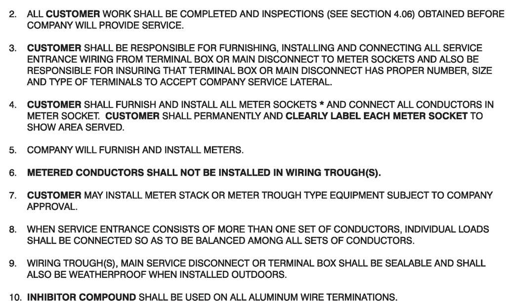
63 56
64 57

65 58
66 59
67 60
68 61
69 62
70 Fax Cover Sheet & Application Forms 63
71 This page was intentionally left blank. 64
72 FAX COVER SHEET Date: To: Allegheny Power s Customer Service Center Fairmont, WV Fax: From: Fax Number: (include area code) Location: Number of pages to follow: If you do not receive pages properly, please contact: (Phone number with area code & contact) Allegheny Power, please accept the following information as an application for service and fax the reference number verification to: (Phone number with area code & contact) (PLEASE TYPE OR PRINT THE INFORMATION USING BLACK INK) 65
73 This page was intentionally left blank. 66
74 APPLICATION FOR NEW RESIDENTIAL ELECTRIC SERVICE (This sheet to follow FAX Cover Sheet provided to you) Customer or Company Name: Customer Mailing Address: (If Customer Name) Date of Birth: Social Security #: (If Company Name) Tax ID # or EIN #: Phone Number: _( ) FAX Number: _( ) Contractor Name: Contractor Phone # : Subdivision Name & Lot No.: County: New Home Address: (Street Address, City, State, Zip Code) Type of Dwelling: Temporary Construction Power Needed: Yes No Service entrance size: 100 amp 200 amp 400 amp Other Service entrance type: Overhead Underground (Charges may apply) Stage of Construction: staked foundation in framing under roof Square Footage of Dwelling (REQUIRED): Electric Heat: Yes No (If yes, indicate type below - if no, go to other heating types) Baseboard kw Electric Furnace kw Heat Pump ton unit and kw auxiliary Geothermal Heat Pump ton unit kw auxiliary Other Heating Types: Natural Gas Bottled Gas Oil Coal Other: Please mark if any of the following apply: Furnace Boiler Baseboard Electric water heater Electric air conditioning: ton unit or size in BTU s Heat Pump ton unit or size in BTU s Detailed directions to new home site: 67
75 Customer Name: Address: APPLICATION FOR UPGRADE RESIDENTIAL SERVICE Account #: Meter # (REQUIRED): Customer Phone #: ( ) Work phone #: ( ) Contact Person for scheduling Phone #: ( ) Fax #: ( ) Directions: Existing Service Size: 60 Amp 100 Amp 200 Amp Upgrading To: 100 Amp 200 Amp 400 Amp Other (Explain): Are you moving the location of meter socket? Yes No Are you changing the point of attachment of overhead line to your house? Yes No (Company shall approve meter socket location and point of attachment. Company may require a move in meter socket location or point of attachment change as a result of upgrade) Are you switching from overhead to underground service? Yes No Please check all applicable equipment upgrades or changes: Entire Service (no need to check other individual boxes) Entrance cable or service mast Meter socket Panel box Main disconnect Grounding Proposed completion date? (Local Service Center will schedule appointments) (ASAP not accepted) ADDITIONAL INFORMATION If adding electric heat? Furnace kw Heat Pump kw Tons Baseboard kw If adding air conditioning? Tons Additional information please note: 68
76 APPLICATION FOR NEW NON-RESIDENTIAL ELECTRIC SERVICE CUSTOMER (Party to be billed) JOB ADDRESS SERVICE TO: CONTACT DETAILS ELECTRIC SERVICE DETAILS LOAD COMMENTS Customer/Company Name: DBA: EIN/SS #: DOB: Telephone #: Billing Address: City: State: Zip Code: Service Address: City: State: Zip Code: County: Township: Development: Lot #: Building/site use: Square Footage: Operating Hours/Day: /Week: Contact Name: Telephone #: Cell #: Alt #: FAX #: Temporary Service Required? Service Entrance Size (Amps): Overhead: Underground: 1 or 3 Phase: Voltage: / Permanent Service - Service Entrance Size (Amps): Overhead: Underground: 1 or 3 Phase: Voltage: / Note: Failure to complete load information may cause service delay. Description 1 PH Hours/Day 3 PH Hours/Day Air Conditioning kw Space Heating - kw Water Heating kw Refrigeration - kw Cooking - kw Process Heating - kw Lighting - kw Misc. - kw Motors total connected kw * Largest Motor - HP Electronic Equip - kw * Provide listing for motors over 6.5 HP (1 PH) or 19.9 HP (3 PH). Stage of construction: Closest Pole or Pad-mounted Transformer #: Directions: Submitted By (required): AP USE ONLY Work Request # A security deposit of $ will be added to your first bill. 69
77 APPLICATION FOR UPGRADE NON-RESIDENTIAL SERVICE Account # Meter # Contact Person: Contact Phone Number: Customer Name: Customer Project Name/Job Location: ELECTRIC SERVICE DETAILS Permanent Service Existing Service Entrance Size (Amps): Overhead: New Service Entrance Size ( Amps ): Overhead: 1 or 3 Phase: Voltage: / Underground: Underground: Note: Failure to complete load information may cause service delay. LOAD Description Air Conditioning kw Space Heating - kw Water Heating kw Refrigeration - kw Cooking - kw Process Heating - kw Lighting - kw Misc. - kw Motors total connected kw * Largest Motor - HP Sensitive Electronic Equip - kw Existing 1PH New 1PH Hours/Day Existing 3PH New 3PH Hours/Day * Provide listing for motors over 6.5 HP (1 PH) or 19.9 HP (3 PH). COMMENTS Additional Notes or Directions: Submitted by (Required): AP USE ONLY Work Request # 70
78 MOTOR SPECIFICATIONS Please provide the following information for each motor over 6.5 HP (Single-Phase) or 19.9 HP (Three-Phase). (List motors starting with the largest.) Motor 1 Motor 2 Motor 3 Motor 4 Motor 5 Description / Purpose / Use Horsepower Rating in HP Voltage & No. of Phases V Ø V Ø V Ø V Ø V Ø Service Factor RPM at full load Locked-Rotor kva Code (letter) LRA (Locked Rotor Amps) (If marked) Indicate Either No. of Starts per Hour or Starts per Day Design Letter (A, B, C or D) FLA (Full Load Amps) Efficiency (If marked) Power Factor (If marked) Reduce Voltage Start Y / N? Provide the Method of Starting /Hr /Day /Hr /Day /Hr /Day /Hr /Day /Hr /Day Y / N Y / N Y / N Y / N Y / N The Typical Methods of Starting are Across the Line, Wye-Delta Starting, Resistor Starting, Reactor Starting, Autotransformer Starting, Solid State Starting, or Adjustable Speed Drive Starting. Motor 6 Motor 7 Motor 8 Motor 9 Motor 10 Description / Purpose / Use Horsepower Rating in HP Voltage & No. of Phases V Ø V Ø V Ø V Ø V Ø Service Factor RPM at full load Locked-Rotor kva Code (letter) LRA (Locked Rotor Amps) (If marked) Indicate Either No. of Starts per Hour or Starts per Day Design Letter (A, B, C, or D) FLA (Full Load Amps) Efficiency (If marked) Power Factor (If marked) Reduce Voltage Start Y / N? Provide the Method of Starting /Hr /Day /Hr /Day /Hr /Day /Hr /Day /Hr /Day Y / N Y / N Y / N Y / N Y / N The Typical Methods of Starting are Across the Line, Wye-Delta Starting, Resistor Starting, Reactor Starting, Autotransformer Starting, Solid State Starting, or Adjustable Speed Drive Starting. Total motor load for motors not shown above: 71
79 This page was intentionally left blank. 72
80
ELECTRIC POLICY INTRODUCTION CHAPTER I GENERAL
 INTRODUCTION This policy has been adopted by the Board of Public Works as a guide to obtaining electric service and to set forth the services available, conditions for service, and standards for materials
GENERAL INFORMATION 1.01 PURPOSE
 GENERAL INFORMATION 1.01 PURPOSE The purpose of this manual is to supply essential information to customers, employees, architects, engineers, contractors, and others concerned with electrical installations
ELECTRIC DIVISION RULES AND PROCEDURES FOR ELECTRIC SERVICE
 Public Works and Utilities 1250 N. Highland St. Mount Dora, FL 32757 352-735-7151 ext. 1805 Fax: 352-735-1539 E-mail: publicworks@cityofmountdora.com ELECTRIC DIVISION RULES AND PROCEDURES FOR ELECTRIC
1. General Requirements
 Ge n e ra lre q u ire me n ts 2016 Electric Service Requirements, 3rd Edition Section 1 Section 1 General Requirements Directory Page 1.1 Manual Purpose and Scope 1 1.2 Customer and Power Company Defined
STOUGHTON UTILITIES ELECTRIC SERVICE RULES AND INFORMATION
 CHAPTER 1 - GENERAL INFORMATION 100. Purpose 101. Codes and rules 102. Continuity of service 103. Frequency, Voltage, and Amperage Limitations 104. High voltages 105. Unusual capacity requirements 106.
2. DEFINITIONS. 2.3 APPROVED Acceptable to the authority enforcing the National Electric Code
 2. DEFINITIONS 2.1 ACCEPTABLE Acceptable to the Company. 2.2 ADVANCED METER A meter that is capable of remote reading, and is capable of storing electric consumption data at specified time intervals of
Metering and Service Installation:
 Table of Contents 1. Metering Installation Requirements, General... 1 2. Type of Service... 2 3. Definitions... 2 4. Who Provides Metering Equipment?... 2 5. Establishment of Service... 2 6. Meter Access...
Section 6 Electric Metering: Residential
 Section 6 Electric Metering: Residential 6.1. Scope This section provides specific information for residential metering that is not covered by the basic requirements in Section 5, Electric Metering: General.
10 Commercial, Industrial, Agricultural Services
 10 Commercial, Industrial, Agricultural Services This section describes the Power Company requirements for commercial, industrial, and agricultural services. This section covers single phase and three
10. METERING General Requirements
 10. METERING 10.1 General Requirements A. The Company will not supply service to a Customer whose wiring is designed for resale of electricity through submetering except for recreational campgrounds, marinas,
UPPCO SERVICE MANUAL
 Revised 01/2015 Section 6 ELECTRIC SERVICE - GENERAL Page 1 of 10 Section 6 Electric Service - General 6-1 Number of Services and Voltages / Meter... 2 6-2 Energy Conversion Factors... 7 6-3 Lightning
BRYAN ELECTRIC DEPARTMENT General Rules and Regulations. Bryan Municipal Utilities 841 E. Edgerton St. Bryan, OH (419)
") BRYAN ELECTRIC DEPARTMENT General Rules and Regulations Bryan Municipal Utilities 841 E. Edgerton St. Bryan, OH 43506 (419) 633-6100 1 Table of Contents Section Page 1. General 3 2. Applicability, General
BRYAN ELECTRIC DEPARTMENT General Rules and Regulations Bryan Municipal Utilities 841 E. Edgerton St. Bryan, OH 43506 (419) 633-6100 1 Table of Contents Section Page 1. General 3 2. Applicability, General
7. Residential Single-Family and Duplex Buildings (Dwellings)
") Sin g le -F a mily a n d Du p le x Bu ild in g s 2016 Electric Service Requirements, 2 nd Edition Section 7 Section 7 Residential Single-Family and Duplex Buildings (Dwellings) Directory Page 7.1 General
Sin g le -F a mily a n d Du p le x Bu ild in g s 2016 Electric Service Requirements, 2 nd Edition Section 7 Section 7 Residential Single-Family and Duplex Buildings (Dwellings) Directory Page 7.1 General
Electric Service Rule No. 2 Description of Service
 Page 1 of 6 A. General 1. All electric service described in this Rule is subject to conditions in the applicable Rate Schedule, other pertinent Rules, and the Electric Service Guides. 2. Alternating-current
AGRICULTURAL UNDERGROUND SERVICE 500 HP OR LESS
 Prepared by: ABB1 AGRICULTURAL UNDERGROUND SERVICE 500 HP OR LESS 05619 Asset Type: Electric Metering Function: Design and Construction Issued by: Lisseth Villareal (LDV2) Date: 07-31-15 Rev. #10: This
For Conduit Inspections
 Underground Conduit Standards - Table of Content 5/8/2017 Section S22 Underground Conduit Standard Index: Description: 00 Table of Content 01 General Notes 02 Definition of Terms 03 Primary Riser Conduit
RESIDENTIAL SUBDIVISION SERVICE REQUIREMENTS SECTION VI RESIDENTIAL SUBDIVISION SERVICE REQUIREMENTS
 SECTION VI SERVICE REQUIREMENTS This section discusses the requirements for establishing electric service to new residential subdivisions in Palo Alto. Subdivisions are normally constructed on dedicated
Installing or Rebuilding Your Electric Service
 Installing or Rebuilding Your Electric Service 2 3 Contents Policies for New and Rebuilt Electric Service 2-4 Paperwork and fees...2 Five-year policy...3 Proposed route location and conditions...3 Construction
KAUAI ISLAND UTILITY COOPERATIVE KIUC Tariff No. 1 Lihue, Kauai, Hawaii Original Sheet 5 RULE NO. 2 CHARACTER OF SERVICE
 Lihue, Kauai, Hawaii Original Sheet 5 RULE NO. 2 A. GENERAL 1. The character of service available at any particular location must be ascertained by the Company business office, and will depend upon the
DIVISION 311 MISCELLANEOUS ELECTRICAL RULES
 DIVISION 311 MISCELLANEOUS ELECTRICAL RULES 918-311-0000 Design, Planning and Lay Out of Electrical Installations by Supervising Electricians A licensed supervising electrician may design, plan and lay
Requirements for Secondary Voltage Revenue Metering (750 V and less)
") Requirements for Secondary Voltage Revenue Metering (750 V and less) To view the latest revision of this document go to: http://www.bchydro.com/ext/metering/ January 28, 2010 Copyright 2008 by BC Hydro.
Requirements for Secondary Voltage Revenue Metering (750 V and less) To view the latest revision of this document go to: http://www.bchydro.com/ext/metering/ January 28, 2010 Copyright 2008 by BC Hydro.
Engineering Rules and Regulations for Electric Service Platte-Clay Electric Cooperative, Inc.
 Engineering Rules and Regulations for Electric Service Platte-Clay Electric Cooperative, Inc. December 2016 (Expires 9/30/18) Kearney Cooperate Headquarters 1000 W. 92 Highway Kearney, MO Platte City District
Electric Service Requirements & Guidelines
 Electric Service Requirements & Guidelines Montana Service Area September 2011 NORTHWESTERN ENERGY Montana Service Area ELECTRIC SERVICE REQUIREMENTS AND GUIDELINES CONTENTS I. GENERAL INFORMATION 1.01
Electric Service and Meter Installations Manual SCANA Corporation 2018
 Electric Service and Meter Installations Manual SCANA Corporation 2018 Revised: January 2018 On file with South Carolina Public Service Commission Table of Contents Section 1: Introduction Customer Call
SALEM CITY POWER ELECTRICAL REQUIREMENTS & STANDARDS MANUAL
 SALEM CITY POWER DEPARTMENT TABLE OF CONTENTS Section 1 General Requirements Purpose...1.1 Codes and Ordinances...1.1 Changes or Conflicts in Requirements and Guidelines...1.1 Application for Service...1.2
SECTION VII METERING INSTALLATIONS
 SECTION VII METERING INSTALLATIONS 1. GENERAL Outdoor metering is required for all new service installations to one, two, and three family detached, semi-detached and row houses. 2. COMPANY FURNISHES AND
Table of Contents. Electrical Service Requirements. 1. General Requirements
 Table of Contents 1. General Requirements 1.1 General Definition.................................................... 1 1 1.2 Booklet Purpose and Organization....................................... 1-1
ELECTRIC SERVICE HANDBOOK INFORMATION & REQUIREMENTS
 ELECTRIC SERVICE HANDBOOK INFORMATION & REQUIREMENTS 2012 EDITION PASCOAG UTILITY DISTRICT ELECTRIC COMPANY 253 Pascoag Main Street Pascoag, RI 02859 PO. BOX 107 TROUBLE AND EMERGENCY ONLY 568-6222 MAIN
Guide for Electric Service and Meter Installations
 Guide for Electric Service and Meter Installations September 2016 American Electric Power Company Meter and Service Guide Preface This booklet is not intended to conflict with the National Electrical Safety
Guide for Electric Service and Meter Installations
 Guide for Electric Service and Meter Installations 2017 American Electric Power Company Meter and Service Guide Preface This booklet is not intended to conflict with the National Electrical Safety Code,
ELECTRIC SERVICE MANUAL
 ELECTRIC SERVICE MANUAL Issued: November 2018 For the most current version of the Jo-Carroll Energy electric service manual please visit www.jocarroll.com TABLE OF CONTENTS Chapter 1. General Information...1
Electric Service Rules
 2017 Electric Service Rules GENERAL INFORMATION TEMPORARY SERVICES OVERHEAD SERVICES UNDERGROUND SERVICES DISTRIBUTED GENERATION METERING HUD MANUFACTURED HOMES FARM SERVICES UTILITY/CATV SERVICES PRIMARY
SECTION 300 OVERHEAD SERVICE
 SECTION 300 OVERHEAD SERVICE 300.01 General Company provides, installs, and maintains service drop to point of delivery approved by Company. Customer provides point of attachment which is acceptable to
UNS Electric, Inc. Rules and Regulations
 Original Sheet No.: 902 A. In these, the following definitions will apply unless the context requires otherwise: 1. Actual Cost: The cost incurred by the Company for labor, materials and equipment including
City of Westerville Electric Division
 Terms and Conditions Of Electric Service City of Westerville Electric Division 139 East Broadway Avenue Westerville, Ohio 43081 614-901-6700 www.westerville.org revised December 2009 1. CONTRACTS, APPLICATIONS
TABLE OF CONTENTS. Important Notices Underground Plant Protection Information. Commercial/Industrial Information Sheet
 DRAWING NUMBER INTRODUCTORY INFORMATION Important Notices Underground Plant Protection Information Code Clearances Commercial/Industrial Information Sheet Work Management Customer Projects Engineering
WELLS RURAL ELECTRIC COMPANY Adopted: March 1976 Revised: March 21, 2017 Reviewed: August 21, 1998 RULE NO. 2
 WELLS RURAL ELECTRIC COMPANY Adopted: March 1976 Revised: March 21, 2017 Reviewed: August 21, 1998 DESCRIPTION OF SERVICE A. General: RULE NO. 2 1. Alternating current service at 60-hertz (cycles per second)
ENTRANCE EQUIPMENT ER D PAGE 1 OF 5
 PAGE 1 OF 5 USE: Requirements for entrance equipment. PREVIOUS REVISION 07-01-98 ORIGINATED 03-94 PREVIOUS NUMBER ER 100 (12-01-81) LATEST REVISION: Updated meter socket labeling specification and instrument
Associated equipment As related to metering equipment: such as the current transformers, CT wiring and test switches.
 APPENDIX Glossary Approval Acceptable to the authority having jurisdiction. Assessor s Parcel Number (APN) Identifying number assigned by the county assessor s office to each taxable building lot in the
APPLICATION FOR PERMIT to construct, operate, maintain, use and/or remove within a county road right-of-way
 IONIA COUNTY ROAD COMMISSION 170 E. Riverside Drive; P.O. Box 76, Ionia MI 48846 (616) 527-1700 (office) or (616) 527-8848 (fax) APPLICATION FOR PERMIT to construct, operate, maintain, use and/or remove
CHAPTER V RESIDENTIAL WIRING
 CHAPTER V RESIDENTIAL WIRING 5.1. THE SERVICE ENTRANCE Buildings and other structures receive the electrical energy through the service entrance. In residential wiring, the electric company supply this
Clark Public Utilities Commercial Electric Service Handbook. This page left blank intentionally.
 This page left blank intentionally. 38 Chapter 4: Commercial Metering / January 2011 APPENDIX Glossary Approval Acceptable to the authority having jurisdiction. Associated equipment As related to metering
Member Installation Standards for Electric Service
 Member Installation Standards for Electric Service December 2010 Edition This document is not copyrighted. Copying is encouraged. First Electric Cooperative Member Installation Standards for Electric Service,
9. Non-Residential Services (Commercial, Industrial, and Agricultural)
") Section 9 2016 Electric Service Requirements, 3rd Edition Section 9 Non-Residential Services Directory Page 9.1 General Requirements 68 9.2 Direct-Connect Metering, Single Installations 69 9.3 Direct-Connect
Section 9 2016 Electric Service Requirements, 3rd Edition Section 9 Non-Residential Services Directory Page 9.1 General Requirements 68 9.2 Direct-Connect Metering, Single Installations 69 9.3 Direct-Connect
Specifications and Requirements for Electric Installations
 Specifications and Requirements for Electric Installations Effective August 2015 Directory of Company Offices Directory of Company Offices Upper Hudson Division Catskill Office 7964 Route 9W Catskill,
Indianapolis Power & Light Company
 Indianapolis Power & Light Company Electric Service and Meter Manual The Electric Service & Meter Manual is not copyrighted and permission is hereby given to reproduce this document. However, the Indianapolis
Electric Service Requirements
 Electric Service Requirements for Residential & Commercial Service Committed to safely and economically provide reliable energy and other services which bring value to its membership. ELECTRIC SERVICE
MECKLENBURG COUNTY. Land Use and Environmental Service Agency Code Enforcement 9/14/11 ELECTRICAL CONSISTENCY MEETING. Code Consistency Questions
 MECKLENBURG COUNTY Land Use and Environmental Service Agency Code Enforcement 9/14/11 ELECTRICAL CONSISTENCY MEETING Code Consistency Questions 1. I recently installed a 45-KVA transformer, 480-volt primary
A member-consumer with a QF facility shall not participate in the Cooperative s electric heat rate program.
 Electric Tariff _2nd Revised Sheet No. 72 Filed with Iowa Utilities Board Cancels _1st Sheet No. _72 Cooperative is a member of Central Iowa Power Cooperative (CIPCO), a generation and transmission cooperative
RULES AND REGULATIONS FOR ELECTRIC SERVICE
 RULES AND REGULATIONS FOR ELECTRIC SERVICE PUBLISHED 1993 TABLE OF CONTENTS SECTION I INTRODUCTION... 5 1. PURPOSE... 5 2. SCOPE... 5 3. COOPERATION... 5 4. CODES... 5 5. RESPONSIBILITY... 5 6. INSPECTION...
CHAPTER 2 TYPES OF SERVICE AND VOLTAGES AVAILABLE 8 Types of Service and Nominal Voltage Furnished
 Table of Contents Page CHAPTER 1 3 Purpose of Service Rules Code Compliance and Inspection Service Entrance Equipment Application for Service Increased Loads Continuity and Quality of Service Neutral Voltages
Published 2018 RULES AND REGULATIONS FOR ELECTRIC SERVICE
 Published 2018 RULES AND REGULATIONS FOR ELECTRIC SERVICE TABLE OF CONTENTS Page No. SECTION I INTRODUCTION 1 A. PURPOSE 1 B. SCOPE 1 C. CORPORATION 1 D. CODES 1 E. RESPONSIBILITY 1 F. INSPECTION 2 G.
ELECTRIC SERVICE RULES UTILITY/CATV SERVICES Issued Jan 2016
 UTILITY/CATV SERVICES CHAPTER 9 900. GENERAL A. Alliant Energy receives many requests for electric service from other utilities; telephone, telecommunications companies, cable television, the Department
CHAPTER 25. SUBSTANTIVE RULES APPLICABLE TO ELECTRIC SERVICE PROVIDERS.
 25.211. Interconnection of On-Site Distributed Generation (DG). (a) (b) (c) Application. Unless the context indicates otherwise, this section and 25.212 of this title (relating to Technical Requirements
Member Installation Standards for Electric Service
 Member Installation Standards for Electric Service June 2014 Edition This document is not copyrighted. Copying is encouraged. Contents Section 1: Foreword, General Information, and Terms...6 1.1 Purpose...
Residential Application for New Electric Service
 Attn: Engineering Department 42 Wescom Rd Johnson VT 05656 1-800-832-2667 ext. 1171 802-635-2331 ext. 1171 802-635-4210 fax Residential Application for New Electric Service INVOICE Attn: Engineering Department
Approved Meter Sockets and Cabinets
 Single Unit Residential Guide 1 PHASE, 120/240 VOLT SERVICES SERVICE CAPACITY OWNED METERING (Metering sockets and cabinets are supplied by Customer). Outdoor meter mounting height is 1730 mm ( 5 8 ) to
MECKLENBURG COUNTY. Land Use and Environmental Service Agency Code Enforcement 2/8/12 ELECTRICAL CONSISTENCY MEETING. Code Consistency Questions
 MECKLENBURG COUNTY Land Use and Environmental Service Agency Code Enforcement 2/8/12 ELECTRICAL CONSISTENCY MEETING Code Consistency Questions 1. I am inspecting a building addition. They have a 480V to
Commercial Electric Service Handbook
 Commercial Electric Service Handbook January 2011 CONTACTS Clark Public Utilities: Website........................................... www.clarkpublicutilities.com Construction Services department (To initiate
INTERCONNECTION STANDARDS FOR CUSTOMER-OWNED GENERATING FACILITIES 25 kw OR LESS PUBLIC UTILITY DISTRICT NO. 1 OF CHELAN COUNTY
 INTERCONNECTION STANDARDS FOR CUSTOMER-OWNED GENERATING FACILITIES 25 kw OR LESS PUBLIC UTILITY DISTRICT NO. 1 OF CHELAN COUNTY Table of Contents Chapter 1. Purpose and scope. Pg 3 Chapter 2. Application
Customer Guide for Electric Service Maryland
 Customer Guide for Electric Service Maryland May 2015 (Page Intentionally Blank) TABLE OF CONTENTS 1.0 INTRODUCTION...1 2.0 DEFINITIONS...2 3.0 GENERAL INFORMATION...6 3.1 Availability & Character of Service...6
SINGLE PHASE WIRING SPECIFICATIONS
 SINGLE PHASE WIRING SPECIFICATIONS 1-866-MEC-ELEC (1-866-632-3532) Office Locations: Hondo Office 237 Hwy 173 N Hondo, TX 78661-0370 Fax 830.426.3335 Dilley Office 1718 W. FM 117 Dilley, TX 78017 Fax 830.965.1425
SANTA CLARA CITY RENEWABLE NET METERING & INTERCONNECTION AGREEMENT
 SANTA CLARA CITY RENEWABLE NET METERING & INTERCONNECTION AGREEMENT This Net Metering and Interconnection Agreement ( Agreement ) is made and entered into as of this day of, 2018, by the City of Santa
57. Line Extensions Policy 1: Individual Residential Customers
 Page 1 of 36 NHPUC NO. 20 - ELECTRICITY DELIVERY Original Page 57 LIBERTY UTILITIES Line Extensions Policy 1: Individual Residential Customers 57. Line Extensions Policy 1: Individual Residential Customers
SOLAR PHOTOVOLTAIC DISTRIBUTED GENERATION CUSTOMER GUIDELINES, APPLICATION & INTERCONNECTION AGREEMENT
 SOLAR PHOTOVOLTAIC DISTRIBUTED GENERATION CUSTOMER GUIDELINES, APPLICATION & INTERCONNECTION AGREEMENT INTERCONNECTION AGREEMENT FOR SOLAR PHOTOVOLTAIC DISTRIBUTED GENERATION THIS AGREEMENT MUST ACCOMPANY
Customer Installation Standards for Electric Service
 Customer Installation Standards for Electric Service Effective June 1, 2008 A transition period will exist from June 1 through December 31, 2008 in which installations may be approved and connected as
Pentahead bolts See note 2. Conduit run as specified. Company facility. Refer to drawing SS8.6-2 or SS8.6-3 STANDARD SERVICE INSTALLATION
 PULL BOX F SECONDARY SYSTEM Typical grade Pentahead bolts See note 2 Conduit run as specified Plastic or fiberglass for grass areas or Polymer concrete for light duty areas (see notes 2, 3, & 4) Company
THREE PHASE WIRING SPECIFICATIONS
 THREE PHASE WIRING SPECIFICATIONS 1-866-MEC-ELEC (1-866-632-3532) Office Locations: Hondo Office 237 Hwy 173 N Hondo, TX 78661-0370 Fax 830.426.3335 Dilley Office 1718 W. FM 117 Dilley, TX 78017 Fax 830.965.1425
COMMERCIAL QUICK REFERENCE
 COMMERCIAL QUICK REFERENCE PROVO CITY POWER STANDARDS ELECTRICAL ENGINEERING UPDATED: 2016 SPECIFICATIONS SUBJECT TO CHANGE WITHOUT NOTIFICATION. 18" MIN. OF TAIL. (NEUTRAL CONDUCTOR MUST BE WHITE OR
COUNTY ROAD COMMISSION RULES FOR THE MOVEMENT OF OVERSIZE OR OVERWEIGHT VEHICLES AND LOADS
 COUNTY ROAD COMMISSION RULES FOR THE MOVEMENT OF OVERSIZE OR OVERWEIGHT VEHICLES AND LOADS General instructions, information and rules governing the issuance of special permits for the movement of oversize
Louisville Gas and Electric Company
 P.S.C. Electric No. 11, Original Sheet No. 57 APPLICABLE In all territory served. AVAILABILITY OF SERVICE Available to any customer-generator who owns and operates a generating facility located on Customer
PUBLIC UTILITY DISTRICT NO. 1 OF LEWIS COUNTY METERING SPECIFICATIONS
 PUBLIC UTILITY DISTRICT NO. 1 OF LEWIS COUNTY METERING SPECIFICATIONS 1. General Metering Requirements a. Interpretation The District s metering requirements shall not be interpreted to conflict with the
Application for Service Residential Subdivision / Development
 Application for Service Residential Subdivision / Development Please complete this application and submit the completed form and attachments to PG&E Application for Service at P.O. Box 24047 Fresno CA
KIUC Service Installation Manual
 KIUC Service Installation Manual Second Edition (November 2016) This manual provides the general requirements for electric service and metering for Kauaʻi Island Utility Cooperative ("KIUC") and is meant
New Service. From... BARRON. Spooner Office: P.O. Box 261 Spooner, WI Barron Office: P.O. Box 40 Barron, WI
 New Service Guidelines and Diagrams From... BARRON www.barronelectric.com email: janderson@barronelectric.com Barron Office: P.O. Box 40 Barron, WI 54812-0040 Spooner Office: P.O. Box 261 Spooner, WI 54801-0261
RESIDENTIAL NEW CONSTRUCTION PACKET CITY OF VERO BEACH UTILITIES. Important Notice to Builders/Contractors/Developers From Electrical Engineering
 1036 20 TH ST. PO BOX 1389 VERO BEACH, FLORIDA 32961-1389 TELEPHONE: (772) 978-5100 FAX: (772) 978-5125 Important Notice to Builders/Contractors/Developers From Electrical Engineering You must contact
Customer Guide to Electric Service Requirements
 Customer Guide to Electric Service Requirements Tillamook People s Utility District Power Services Group 1115 Pacific Avenue Tillamook, Oregon 97141 OFFICE: 503.815.8629 FAX: 503.815.8648 TOLL FREE: 800.422.2535
INTERCONNECTION STANDARDS FOR PARALLEL OPERATION OF SMALL-SIZE GENERATING FACILITIES KILOWATTS IN THE STATE OF NEW JERSEY
 INTERCONNECTION STANDARDS FOR PARALLEL OPERATION OF SMALL-SIZE GENERATING FACILITIES 10-100 KILOWATTS IN THE STATE OF NEW JERSEY January 1, 2005 Rockland Electric Company 390 West Route 59 Spring Valley,
The cost estimation methodology used to update the charges and credits is the same methodology the Company utilized in the prior year s filing.
 LISA D. NORDSTROM Lead Counsel lnordstrom@idahopower.com December 28, 2018 Public Utility Commission of Oregon Filing Center 201 High Street SE, Suite 100 P.O. Box 1088 Salem, Oregon 97301 Re: Tariff Advice
Customer Guide for Electric Service Ohio
 Customer Guide for Electric Service Ohio September 2017 (Page Intentionally Blank) TABLE OF CONTENTS 1.0 INTRODUCTION...1 2.0 DEFINITIONS...2 3.0 GENERAL INFORMATION...6 3.1 Availability & Character of
ELECTRIC SERVICE REQUIREMENTS
 ELECTRIC SERVICE REQUIREMENTS Single-Family and Duplex Dwelling Connection Checklist A customer building a new single-family or duplex dwelling and connecting to the Power Company s electrical system may
9/7/2010. Objectives. Article 90. Introduction NEC Significant Changes. Review significant revisions in the 2011 NEC
 2011 NEC Significant Changes Courtesy of NJATC Courtesy of NFPA Presented By: Michael J. Johnston Executive Director of Standards and Safety, NECA Objectives Review significant revisions in the 2011 NEC
7 Single Family Service
 7 Single Family Service 7. General The location of the service entrance on the Customer s premises is an important consideration. For clearance and location information see section 5 (Clearances). Consult
TEMPORARY SERVICE TABLE OF CONTENTS PUD SERVICE TERRITORY AND CONTACTS CHAPTER ONE - INTRODUCTION CHAPTER TWO - TEMPORARY OVERHEAD SERVICE
 Electrical Service Requirements TEMPORARY SERVICE TABLE OF CONTENTS PUD SERVICE TERRITORY AND CONTACTS CHAPTER ONE - INTRODUCTION Inspections and codes Underground Utility locates Meter socket requirements
CONTENTS BY CHAPTER. Chapter 2: COMPANY EQUIPMENT ON CUSTOMER PREMISES
 CONTENTS BY CHAPTER Chapter 1: GENERAL INFORMATION Chapter 2: COMPANY EQUIPMENT ON CUSTOMER PREMISES Chapter 3: SERVICE ENTRANCES Chapter 4: METERING INSTALLATION Chapter 5: CUSTOMER-INSTALLED SERVICE
Electric Service Guidelines TSN
 Electric Service Guidelines TSN 449260 May 2017 Important Notice Regarding Removal of Oncor Electric Delivery Company LLC Meters to Perform Work on Customer s Premise Effective October 15, 2013, as provided
SPECIFICATIONS FOR RESIDENTIAL CONSTRUCTION
 Roseville Electric SPECIFICATIONS FOR RESIDENTIAL CONSTRUCTION REVISED 04/25/18 Specifications for Residential Construction Revision List REVISION Date Page No. Description 03/20/00 6.1-6.2 Added Armorcast
ENGINEERING SPECIFICATION
 December 206 ENGINEERING SPECIFICATION No. of 6 DATE: 2-9-6 CATEGORY SUBJECT TABLE OF CONTENTS. Overview... 2 2. General Requirements for Service... 3 3. Definitions... 3 4. Abbreviations... 5 5. References
201 S. Anaheim Blvd. Page No Anaheim, CA RULE NO. 2 DESCRIPTION OF SERVICE
 201 S. Anaheim Blvd. Page No. 3.2.1 A. GENERAL 1. The character of electric service available at any particular location should be ascertained by inquiry at the City's Electrical Engineering Division office.
AMENDMENT ELECTRIC SERVICE MANUAL 2014
 AMENDMENT (Pages 20,43,50,72,74,,76,78,83,86,99) ELECTRIC SERVICE MANUAL 2014 Effective April 1, 2015 18-7 6.0 SERVICE AND SERVICE ENTRANCES (General), Continued Conductor Sizing It is recommended that
Noble County Rural Electric Membership Corporation
 Albion, Indiana Page 1 of 5 SCHEDULE NB-1 RESIDENTIAL NET BILLING I. AVAILABILITY This Net Billing Rate is available to any residential member in good standing of Noble REMC (Noble) who owns and operates
Northeastern Rural Electric Membership Corporation Schedule DG-2 Columbia City, Indiana Page 1 of 5
 Columbia City, Indiana Page 1 of 5 SCHEDULE DG-2 LARGE POWER DISTRIBUTED GENERATION I. AVAILABILITY This Distributed Generation Rate is available to any member in good standing of Northeastern REMC (Northeastern)
Commercial & Industrial
 The Empire District Electric Company Requirements For Electric Service And Meter Installations Commercial & Industrial (800) 206 2300 The latest revision of this book can be found at www.empiredistrict.com
ROCHESTER PUBLIC UTILITIES
 ROCHESTER PUBLIC UTILITIES ELECTRIC SERVICE RULES AND REGULATIONS Revised August 2011 INTRODUCTION Rochester Public Utilities (hereafter referred to as RPU) has assembled this booklet to assist its customers
See NT POWERCOS , Classification Based On Service Size.
 Newmarket-Tay Power Distribution Ltd. Conditions of Service Number: NT POWER COS 310 01 Issue Date: July, 2007 Next Review Date: February, 2020 Residential 1. Preamble This section covers all items that
KAUAI ISLAND UTILITY COOPERATIVE KIUC Tariff No. 1 RULE NO. 17 NET ENERGY METERING
 Third Revised Sheet 55a Cancels Second Revised Sheet 55a A. ELIGIBLE CUSTOMER-GENERATOR RULE NO. 17 NET ENERGY METERING Net energy metering is available to eligible customer-generators, defined as, permanent
M.P.S.C. No. 2 Electric Third Revised Sheet No. 65 (Rate Case) Cancels Second Revised Sheet No. 65
 Cancels Second Revised Sheet No. 65") M.P.S.C. No. 2 Electric Third Revised Sheet No. 65 (Rate Case) Cancels Second Revised Sheet No. 65 CLASS OF SERVICE: CUSTOMER GENERATING SYSTEMS OVER 20 KW RATE CGS 1 AVAILABILITY To customers owning generating
M.P.S.C. No. 2 Electric Third Revised Sheet No. 65 (Rate Case) Cancels Second Revised Sheet No. 65 CLASS OF SERVICE: CUSTOMER GENERATING SYSTEMS OVER 20 KW RATE CGS 1 AVAILABILITY To customers owning generating
D9-3. No. WIRING DIAGRAM CONNECTIONS FOR UNDERGROUND SELF CONTAINED METERS JRH JED krich95 LINE LINE ABCN SOURCE SOURCE GROUND GROUND STUD STUD SOURCE
 SOURCE 20V 240V STUD (PER NEC) A customer supplied and installed teaser wire is required from the neutral lug to a 5th terminal mounted on the left side of the meter block between the line and load terminals.
TEMPORARY ELECTRIC WIRING FOR CARNIVALS, CONVENTIONS, EXHIBITIONS, FAIRS AND SIMILAR USES
 INFORMATION BULLETIN / PUBLIC - ELECTRICAL CODE REFERENCE NO.: LAMC 93.0230 Effective: 3-24-69 DOCUMENT NO. P/EC 2002-006 Revised: 11-17-00 Previously Issued As: RGA #7-69 TEMPORARY ELECTRIC WIRING FOR
THE PUBLIC SERVICE COMMISSION OF WYOMING
 NAME: Powder River Energy Corporation WY PSC Tariff No. 7 ADDRESS:, Sundance, WY 82729 THE PUBLIC SERVICE COMMISSION OF WYOMING TARIFF RATE RIDER 5th Revised Sheet No. 1 Cancels 4th Revised Sheet No. 1