ELECTRIC SERVICE HANDBOOK INFORMATION & REQUIREMENTS
|
|
|
- Rosamond Burns
- 5 years ago
- Views:
Transcription
1 ELECTRIC SERVICE HANDBOOK INFORMATION & REQUIREMENTS 2012 EDITION
2 PASCOAG UTILITY DISTRICT ELECTRIC COMPANY 253 Pascoag Main Street Pascoag, RI PO. BOX 107 TROUBLE AND EMERGENCY ONLY MAIN OFFICE GENERAL MANAGER MICHAEL KIRKWOOD Phone: ASSISTANT GENERAL MANAGER WIILIAM J. GUERTIN Phone: Cell: DISTRIBUTION FOREMAN CHRISTOPHER PICCARDI Phone: Cell: METER TECHNICIAN JOHN R. BLODGETT Phone: Cell: SERVICE AREA Pascoag Bridgeton Harrisville
3 CONTENTS ARTICLE 100 General Information 9 Section 101 Purpose Scope Effective Date and Revisions Enforcement of Rules Space Requirements Advisory Service Excavations in Roads and Highways Construction in the Proximity to Conductors Attachments to Utility Poles.15 ARTICLE 200 Request for Service Information 17 Section 201 Where to Apply When to Apply Availability of Service Public Grants, Special Permits and Easements Additional Loads and/or Alteration of Service Contribution-in Aid-of-Construction Inspection Certificates Temporary Service and Installation Charges Voltage Sensitive Equipment 25 ARTICLE 300 Services.27 Section 301 General Service and Design Standard Service Characteristics Customer s Emergency Generator Co-Generation Final Connections Transformer Vaults 31
4 ARTICLE 400 Service Installations Overhead..33 Section 401 Secondary Services Overhead Maximum Spans for Service Drops Point of Attachment Overhead Single-Phase Line Extensions Three-Phase Line Extensions Service to Mobile Homes Service to Commercial and Industrial Customers Primary Lines to Transformer Installations on Customer s Premises Three-Phase Transformer Installations...42 ARTICLE 500 Service Installations Underground 45 Section 501 Secondary Underground Service from Company Overhead Lines Secondary Underground Service from Company Underground System Underground Residential Distribution (URD) Primary Underground Supply from Company Overhead Lines Primary Underground Supply from Company Underground System Three-Phase Transformer Installations Ground Level.54 ARTICLE 600 Service Entrance.57 Section 601 Size of Conductors Service Equipment Disconnecting Means Assigning Location of Service and Metering Equipment Unmetered Conductors Fuses Anchorage for Service Drop Conductors Building Alterations Affecting the Electric Service Connection to Company s Overhead Conductors Grounding 63 ARTICLE 700 Wiring and Voltage Requirements...65 Section 701 Single-Phase Service...67
5 703 Three-Phase Four Wire Service Electrical Fluctuating Loads Power Factor Power Factor Correction Capacitors Off-Peak Water Heaters..68 Article 800 Meters 69 Section 801 Scope Meter and Equipment Seals Standard Meter Installations Assigning Location of Service and Metering Equipment Outdoor Meter Locations Indoor Meter Locations Meter Boards Clearances Identification of Meter Sockets and Customer Disconnecting Means Unmetered Conductors Moving or Removing Metering Equipment Meter Sockets Cover Plates Installation of Sockets Socket Connections Grounding of Meter Sockets Instrument Transformers and Enclosures Meter Test Switches and Sockets Use of Instrument Transformer Cabinets.82 ARTICLE 900 Motors..83 Section 901 General Single-Phase Motors and/or Air Conditioners Three-Phase Motors and/or Air Conditioners Protective Devices Protection Against Single-Phase Operation Undervoltage Protection Overload Protection Protection Against Phase Reversal..89 APPENDIX...91 Excerpts from General Laws Massachusetts...93 Excerpts from General Laws Rhode Island 107
6 ILLUSTRATIONS Figure 1 Temporary Service Structure Overhead Distribution.120 Figure 2 Temporary Service Underground Residential Distribution Figure 3 Typical Service Mast Construction Low Buildings With Roof Overhang Figure 4 Typical Service Mast Construction Low Buildings Without Roof Overhang..123 Figure 5 Terminal Box.124 Figure 6 Typical Transformer Pad Figure 7 Minimum Wire Clearance From Buildings And Signs..126 Figure 8 Minimum Vertical Service Clearance 128
7 ARTICLE 100 GENERAL INFORMATION SECTION 101 PURPOSE SCOPE EFFECTIVE DATE AND REVISIONS ENFORCEMENT OF RULES SPACE REQUIREMENTS ADVISORY SERVICE EXCAVATIONS IN ROADS AND HIGHWAYS CONSTRUCTION IN THE PROXIMITY TO CONDUCTORS ATTACHMENTS TO UTILITY POLES 15
8 101 PURPOSE. Information and requirements for Electric Service, is issued to provide information to Pascoag Utility District Associates customers, electrical contractors, architects and engineers, so that electrical installations, to be connected to the Company s system, may be made in a standard, uniform and proper manner. These requirements supplement the Company s Schedule of Rates and Terms and Conditions filed from time to time with the state regulatory agencies. It is not intended that this booklet give complete coverage for wiring details and other lawful requirements. It has been prepared as a guide and is supplementary to the applicable national, state and local electrical codes, safety code, OSHA requirements, and to ordinances passed by authorities having jurisdiction. This booklet shall not be construed as relieving the customer and/or his contractor from the responsibility of installing wiring in accordance with the rules and regulations published by authorities having jurisdiction, nor shall the Company be responsible for the condition of the customer s wiring and equipment. 103 SCOPE. The information contained in this booklet applies primarily to electric service requirements for installations at voltages not exceeding 480 volts. Contact the Consumer Services Department for information on services not covered in this booklet. 105 EFFECTIVE DATE AND REVISIONS. This issue of Information and Requirements for Electric Service supercedes all previous issues and is effective at once for all new construction, with reasonable allowance for the completion of work in progress or already under contract. Revisions of this information will be made when necessary and the Company reserves the right to make such revisions. The Company cannot guarantee to give notice of revisions to persons who may have received this book. 107 ENFORCEMENT OF RULES. The Company requires that all wiring intended for connection to its electric system shall be installed in accordance with the rules of the applicable national, state and local electrical codes and with the laws and ordinances of state, city and town authorities having jurisdiction over the area in which the work is located, and with the requirements set forth in the succeeding pages of this booklet. All connections to the Company s system shall be designed, installed and operated in a manner that will not cause undue disturbance to other customers, and shall not handicap the Company in maintaining proper system conditions.
9 The Company reserves the right to require notification and inspection of the installation, to ensure compliance with the requirements of this booklet, during construction and prior to energizing the service. The Company requires the customer to notify the Consumer Services Department for inspections and/or when service is completed and ready to be energized. The Company reserves the right to refuse to connect and/or the right to disconnect a service where the customer s installation does not comply with the provisions and requirements outlined above SPACE REQUIREMENTS. The Company requires adequate space at an acceptable and accessible location for the purpose of erecting, removing, operating or maintaining its facilities, including the reading and testing of its meters, such locations to be approved by the Company. 111 ADVISORY SERVICE. The Company offers an advisory service to all customers, architects, contractors and engineers, to assist them in obtaining installations that conform to the requirements of the Company. All persons are encouraged to use the advisory services of the Company with respect to applications of power, electric heating, lighting, water heating, etc. Such advice may avoid delays and result in greater satisfaction and more efficient use of electrical service. Consumer Services Departments are responsible for negotiations with customers. They should be consulted on matters of rates, the availability of service and the cost, if any, to supply each service. Although the Company endeavors to keep informed of conditions under which customers use electricity, the customer should contact the Company anytime a significant change in their use of patterns occur to request a review of available rates. The customer may request a rate review at any time by contacting the Consumer Services Department. The Company does not in any way give any warranty, expressed or implied, as to the adequacy, safety, or other characteristics of any equipment, wires, appliances, or devices owned, used or maintained by customers. 113 EXCAVATIONS IN ROADS AND HIGHWAYS. All contractors, municipal departments and other utility companies which may be required to excavate roads or highways shall provide to the Maps and Records Department of the appropriate Company a minimum of two working days written notice of such intent to excavate. Upon request, drawings will be made available that show the approximate location of underground ducts and cables, if present.
10 Note: For work done in Rhode Island, see appendix General Laws of Rhode Island and contact DIG SAFE, Tel DIG SAFE. 115 CONSTRUCTION IN THE PROXIMITY TO CONDUCTORS. A. Construction in the proximity to any electrical conductor shall not be started until the Company has been contacted and it has been determined that such construction will not violate the requirements of the applicable electrical codes, National Electrical Safety Code, laws of the state and/or local municipal authorities. B. Swimming Pools shall not be constructed in the proximity to any electrical conductor per the applicable electrical codes. C. The cost of relocation of electrical facilities to comply with A and B above shall be borne by the customer. 117 ATTACHMENTS TO UTILITY POLES. All unauthorized attachments to utility poles are subject to removal without notice. Any customers or contractors seeking permission to install privately owned facilities such as telephone communication conductors must request permission in writing to the Consumer Services Department. If permission is granted, the Company will arrange to have a Pole Attachment Agreement prepared for signature by the participating utility companies and the customer.
11 ARTICLE 200 REQUEST FOR SERVICE INFORMATION SECTION 201 WHERE TO APPLY WHEN TO APPLY AVAILABILITY OF SERVICE PUBLIC GRANTS, SPECIAL PERMITS AND EASEMENTS ADDITIONAL LOADS AND/OR ALTERATION OF SERVICE CONTRIBUTION-IN-AID-OF- CONSTRUCTION INSPECTION CERTIFICATES TEMPORARY SERVICE AND INSTALLATION CHARGES VOLTAGE SENSITIVE EQUIPMENT 25
12 201 WHERE TO APPLY. All requests for service information should be directed to the Consumer Services Department. An application to have electricity turned on or off should be made, at a convenient business office of the Company serving the location of the installation, either in person or by telephone. Business offices are listed in front of this booklet. 202 WHEN TO APPLY. In order for the Company to design and construct the new or changed facilities that may be needed to meet the customer s requirements, it is essential that an application for new, additional or changes to service be made as early as possible. All contracts and correspondence with the Company for single phase residential services less than 400 Amperes are to be directed to the Residential Service Group Meter Section for the Pascoag Utility District. All three phase service requests should be directed to the Consumer Service Departments at all locations. When developing plans and specifications for single-phase service 400 amperes and larger three phase service 200 amperes and larger the procedure to follow is: A: Communications 1. All contacts and correspondence with the Company should be directed to the Consumer Services Department. 2. The customer or his representative (architect, engineer, electrical contractor) should notify the Company as soon as the planning and design for the project starts and provide the location, type of project, size of load, and estimated completion date. This advance notice is required to allow time for the Company to order equipment with long delivery time. Also, to avoid delays, the customer should provide, at the earliest possible date, the information necessary for the Company to obtain any easements and grants required. See section 205. B. Design 1. The customer or his representative should provide a set of 75 percent completed plans to the Company for use in designing and laying out the required changes or additions to the distribution system. The plans should include, but not be limited to, the following: a. Electrical Loads b. Service Location c. Summary of total connected loads (kw) d. One Line Diagram Showing the Electrical Service and Metering Installation Including Service Size, Voltage, Number of Phases (Single or Three) and Metering (Master or Individual)
13 e. Location of Building f. Size of Building g. Roads or Parking Area h. Location of Water, Drains, Gas and Telephone i. Topographical Elevations of Area and Building Elevations 2. The Distribution Engineering Section will review all submitted plans and information for completeness. A preliminary review will be made regarding the amount of time and materials necessary to design and complete the project. This information will be furnished to the customer or their representatives within an agreed upon time frame. Any meetings required by the interested parties will be coordinated by the Consumer Services Department 3. All Company design work will be laid-out on the customer s plans and returned via the Consumer Services Representative along with any other pertinent information. e.g. metering information C. Approval The customer or his representative should supply two sets of final plans and specifications ready for bidding or construction, to the Company for review by the Engineering and Meter Departments. One set of plans will be returned with a statement of approval and/or a list of changes required. 203 AVAILABILITY OF SERVICE. Before ordering any electrical equipment, or starting any electrical construction which would affect the Company s electrical system, the customer should contact the Company to insure that the desired and/or additional capacity is available. The Company does not accept responsibility for the information given orally relative to the type of service available at specific locations. The Company will only accept responsibility for written information from an authorized company representative relative to a specific project. 205 PUBLIC GRANTS, SPECIAL PERMITS AND EASEMENTS. Before wires can be run over, under or across public ways, the company must obtain public grants and in many cases must obtain special permits. These grants and permits can be issued in some instances only after public hearings are held. Where it is found necessary that Company wires and equipment must be installed over, under or across the property of a second party or a multi-customer installation such as a shopping center, the customer must obtain, at his/her expense, the necessary signatures on an easement prepared by the Company. Under such circumstances, delays to service connections can be avoided by applying for service at the earliest possible date. Any questions or details pertaining to the required easement should be clarified with the Company. 207 ADDITIONAL LOADS AND/OR ALTERATION OF SERVICE. Company facilities are designed to meet the customer s initial requirements at the time the service is installed. When an additional load is contemplated, the Company should be notified as early as possible so that proper provisions can be made to furnish the additional service.
14 Failure to notify the Company of an increase in load may result in improper billing, burning out of apparatus, or serious interruption to service. Whenever changes are made to an existing service installation involving relocation, replacement, and/or additions, the entire service installation may require rebuilding and/or relocation to conform to the present requirements of the Company and applicable electrical codes. The decision as to the actual changes required will be determined by consultation with the Company and the Municipal Wiring Inspector. In some instances there may be a charge by the Company for service relocation. Contractors requesting these charges for bidding purposes shall submit necessary information at least three weeks prior to the required date. 209 CONTRIBUTION-IN-AID-OF-CONSTRUCTION. Information relating to the portion of the service construction cost to be borne by the customer, if any, will be supplied by the Consumer Services Department. Customers should request this information before ordering equipment or starting construction. Any contribution required must be paid-in-full prior to the commencement of any construction by the Company. Any customer/contractor/developer that turns over ownership of electric facilities to the Company will be responsible for a Tax Adjustment Factor (TAF) in accordance with the Tax Reform Act of The TAF must be paid in full prior to the Company taking ownership of the equipment and before any cable or transformers are installed. 213 INSPECTION CERTIFICATES. The Company is not allowed to energize wiring until written approval is received in the form of an Inspection Certificate from an authorized inspector. 215 TEMPORARY SERVICE AND INSTALLATION CHARGES. A temporary service will, in general, be supplied by the Company for periods not exceeding six (6) months. Upon request from the customer, the Company may grant an extension for such service. For temporary service, the customer will pay an amount equal to the cost of installing and removing the Company s service facilities, plus the cost of nonsalvageable material used. Estimates of these charges will be furnished by the Company on request. The customer shall supply a suitable structure as follows: A.OVERHEAD The customer shall provide a service entrance which meets the requirements of a permanent installation with respect to service drop clearances, metering, grounding and safety. The service entrance may be installed on a guyed or braced 4 inch x 6 inch timber structure which meets the specifications and installation requirements of the Company. Where a laminated 4 inch x 6 inch structure is to be assembled using two 2 inch x 6 inch planks, these planks should be bolted together at intervals not exceeding 4 feet *See Figure 1. B. UNDERGROUND RESIDENTIAL DISTRIBUTION (URD) See figure No. 2. C. UNDERGROUND FROM UNDERGROUND SYSTEM
15 Consult the Company. *NOTE: Designs for structures other than those specified in this booklet must be submitted to the Company for approval before starting construction. 217 VOLTAGE SENSITIVE EQUIPMENT. Customers owning or planning to purchase sensitive electronic equipment should be aware that this type of sensitive electronic equipment can be extremely sensitive to power system transients or loss of voltage. Customers should consult the manufacturer of their equipment for suitable devices to protect against the foregoing. The Company is not responsible for voltage variations which may be caused by switching, lightning surges, vehicles hitting utility poles, or other conditions of an emergency nature.
16 ARTICLE 300 SERVICES SECTION 301 GENERAL SERVICE AND DESIGN STANDARD SERVICE CHARACTERISTICS CUSTOMER S EMERGENCY GENERATOR CO-GENERATION FINAL CONNECTIONS TRANSFORMER VAULTS.18
17 301 GENERAL. Alternating current, 60-hertz service is supplied throughout the territory served by the Company. Characteristics of the service available at any specific location should be obtained from the Company before ordering any new, additional or replacement equipment. Normally, only one service drop or lateral will be installed for a customer at a given location. Two or more service drops or laterals may be installed at the option of the Company, when approved by the Municipal Wiring Inspector, to provide suitable capacity to supply special loads or to meet unusual conditions. When electricity is metered by more than one meter, the cost of service delivered through each meter will be computed separately and the rate for the second meter will be set at a commercial rate. All Circuits shall be metered. This includes fire-alarms, pumps, ground-fault circuit-interrupters, etc. 302 SERVICE AND DESIGN. The Company will supply a service to the customer the least expensive way, providing it is in keeping with good construction practices and is revenue justified. Refer to Sections 407 and 409 for information relative to cost of providing service. Any additional expense to service the customer in an alternative manner including the cost of alternate transformers and other such equipment and hardware will be paid by the customer. 303 STANDARD SERVICE CHARACTERISTICS. The characteristics and nominal voltages of the various forms of service commonly supplied by the Company are as follows: A. 120/240 volts, single-phase, three wire. B. 208Y/120 volts, three-phase, four wire. C. 480Y/277 volts, three-phase, four wire. Primary voltages may be available at the option of the Company. 305 CUSTOMER S EMERGENCY GENERATOR. Where the customer installs an emergency generator for the purpose of supplying all or part of the load in the event of an interruption of service, the customer s wiring shall be arranged so that no electrical connection can occur between the Company s service and the customer s other source of supply. 306 CO-GENERATION. When a customer intends to become a co-generator utilizing new or existing on-site generation, he shall contact the Company in writing in advance of procuring any equipment. This is necessary to determine the availability of service,
18 technical or special equipment requirements and any associated cost which may be essential to serve this customer. The Company does not accept responsibility for information given orally relative to the type of service available at specific locations. The Company will only accept responsibility for written information from an authorized company representative relative to a specific project. 307 FINAL CONNECTIONS. Only the Company, or authorized persons working in accordance with Company specifications, is allowed to connect or disconnect a customer s wiring to Companies facilities. 309 TRANSFORMER VAULTS. Where large capacity services are required, and/or where an outdoor location for transformers is not available, the Company may require the customer to furnish a suitable vault or metal enclosure on his/her premises for the necessary transformers and protective equipment. Such vaults or enclosures must meet the requirements of the applicable electrical codes and the Company.
19 ARTICLE 400 SERVICE INSTALLATIONS OVERHEAD SECTION 401 SECONDARY SERVICES OVERHEAD MAXIMUM SPANS FOR SERVICE DROPS POINT OF ATTACHMENT OVERHEAD SINGLE-PHASE LINE EXTENSIONS THREE-PHASE LINE EXTENSIONS SERVICE TO MOBILE HOMES SERVICE TO COMMERCIAL AND INDUSTRIAL CUSTOMERS PRIMARY LINES TO TRANSFORMER INSTALLATIONS ON CUSTOMER S PREMISES THREE-PHASE TRANSFORMER INSTALLATIONS 19
20 401 SECONDARY SERVICES-OVERHEAD. In cases where service drops of 400 amperes or less are supplied from a transformer(s) on a pole, the service drop will be supplied and installed by the Company. Customers requiring secondary service drops larger than 400 amperes shall supply all secondary wiring and transformer bus wiring, including any necessary transformer lugs and/or connectors, as specified by the Company. The customer shall install all equipment at the building and the Company will install the customer s equipment at the pole at no charge. Preferred location for transformer banks is on customer s property at a location acceptable to the Company. If the customer installs two or more services in the same location or adds one or more services to an existing service drop, the ampacity of the service drop required shall be equal to the sum of the individual service ampacities. If the customer installs multiple conductors in a service or installs additional conductors in an existing service, the ampacity of the service drop shall be equal to the sum of the individual conductor ampacities. Where compression connectors are to be used, the customer may be required to supply the proper tool and die. 403 MAXIMUM SPANS FOR SERVICE DROPS. The maximum single span distance the Company will run its overhead service drop conductors is dependent on such factors as building heights, size of conductors and necessary clearances. This distance will be determined by the Company. 405 POINT OF ATTACHMENT. The service drop shall be attached to the building or other structure at a suitable point, determined by the Company. The Company will not permit a service drop to be attached to an intermediate building or structure. To prevent the entrance of moisture into the service entrance conductors, the service entrance weather cap shall be so located that the connection between the service entrance and service drop conductors must be made at a point below the level of the weather cap. The service drop building attachment should be accessible from a ladder without climbing on a roof and shall be of a height to permit the following clearances: A. CLEARANCE FROM GROUND-(SERVICE BELOW 600V) Above finished grade, sidewalks or from any platform or projection from which they might be reached. 12 feet*
21 Over residential driveways not subject to truck traffic. 15 feet** Over commercial areas, parking lots, agricultural or other areas subject to truck traffic. 15 feet Over public streets, roads, alleys and driveways other than residential. 16 feet Over state highways in RI 18 feet Table Reference: Applicable codes *The distance to the bottom of drip loops may be reduced to 10-6 for service drops limited to 300V to ground and 10 for multiplex service drops limited to 150V to ground. **For residential driveways where the height of attachment to a building or installation does not permit service drops to meet this value, the clearance may be reduced to 12-6 for service drops limited to 300V to ground and 12 for multiplex service drops limited to 150V to ground. Wherever the type of building will not provide these clearances and the building is within a normal service span, the customer will be expected to provide an approved support or attachment or install an underground service. In the event a mast-type riser is required to attain the required height, it shall be of such construction and so supported that it will withstand the strain imposed by the service drop. A typical serviceentrance mast installation is shown in Figures 3 and 4. B. CLEARANCE OVER A ROOF In general, service drop conductors shall not pass over roofs. When this is unavoidable, conductors shall have a clearance of not less than eight feet from the highest point of roofs over which they pass. The only exceptions to this clearance are those allowed by the electrical codes. 407 OVERHEAD SINGLE-PHASE LINE EXTENSIONS. When an extension of an overhead line is necessary to provide service to a permanent structure, the length of the extension along the public street shall be determined. If this length exceeds the limit set forth in paragraph A below, an agreement must be negotiated to compensate the Company for the cost of all construction in excess of this limit. The length of the extension shall be measured from the last pole carrying the circuit with the required voltage from which a customer can be served. If the extension involves both public streets and private property, the negotiated agreement will cover the entire extension and any payment required will be the sum of the deposit required under Paragraph A below and any contribution required under paragraph B below.
22 All construction will be owned and maintained by the Company. The Company will begin construction of a line under this policy when the customer(s) to be supplied has signed the necessary Letter of Agreement. If a Letter of Agreement is not required, construction under this policy will begin when the customer(s) to be supplied has completed most of the wiring of the premises to be supplied. Construction will not commence or continue during periods of inclement weather or other abnormal conditions. Public grants, special permits and easements may be required for line extensions. See Section 205. A. EXTENSIONS ALONG A PUBLIC HIGHWAY 1. The Company may, at no charge to the customer, extend an overhead single-phase line up to 500 feet, along an accepted public street, having a minimum acceptable right-of-way width of 33 feet when normal construction, as defined by the Company, can be used. When, in the Company s opinion, the potential for additional load growth in a reasonable time exists, the distance may be extended. 2. When the single-phase overhead line extension exceeds 500 feet, the Company may require the customer to provide a contribution-in-aid-ofconstruction. Consult the Consumer Services Department for details. 3. For extensions in areas with abnormal conditions such as unpaved roadways or undefined roadways requiring excessive tree clearing, surveying, etc., the excess cost will be treated as the same as above. B. EXTENSION OVER PRIVATE PROPERTY 1. The Company will, at no charge to the customer, extend an overhead single-phase line up to two pole sections per service. The line extension is for distance only. The Company must be granted an acceptable right-ofway for construction and maintenance of the line extension. 2. For extensions in excess of two poles the customer must negotiate a contractual agreement to provide for a contribution towards the cost of the construction of the extension beyond the second pole based on the following: a. Installed unit cost for each pole. b. Installed unit cost for each guy. c. Installed unit cost for each foot of extension. d. Installed full cost of abnormal construction such as long span, extra large conductor or ledge. Initial tree trimming on private property will be done by the customer at their expense. Consult Consumer Services Department for details.
23 If a customer desires more than one service in order to separately meter another building on the same property, the entire cost of installing the additional service will be paid by the customer. 409 THREE-PHASE LINE EXTENSIONS. All three-phase line extensions will be considered on an individual basis. If anticipated revenue does not support construction costs the customer will be required to make a contribution-in-aid-of-construction. Customers requesting this type of service should contact the Consumer Services Department as well in advance of construction as possible. This must be done to determine availability, construction requirements and cost of the proposed extension SERVICE TO MOBILE HOMES. Overhead or underground service is available to mobile homes under the arrangements as provided for other individual residences with the following considerations: A. The meter facilities and service equipment shall be installed on a permanent supporting structure or pole provided by the owner and located adjacent to the mobile home. B. It is recommended that an approved rain-tight disconnecting means having a capacity of not less than 100 amperes be provided for each home at the meter location. Pre-wired combination meter and service pedestal may be used subject to advance approval by the Company SERVICE TO COMMERCIAL AND INDUSTRIAL CUSTOMERS. The customer or his agent shall consult the appropriate Consumer Services Department for information regarding the availability of service, the appropriate rate and specific details dealing with overhead or underground construction costs, if any, to supply the required service. Customers may be required to supply space for the Company s equipment on private property PRIMARY LINES TO TRANSFORMER INSTALLATIONS ON CUSTOMER S PREMISES. Primary lines to transformers located on secondary metered customer s premises will normally consist of overhead facilities installed and maintained by the Company. Refer to sections 407 and 409 for information relative to cost of providing service. 417 THREE-PHASE TRANSFORMER INSTALLATIONS*. Customers whose services require an ultimate transformer capacity of 500 kva or less may be served with either an overhead or ground-level transformer installation. Customers whose services require an ultimate transformer capacity of more than 500 kva will be served from ground-level transformer installation.
24 The Company reserves the right to give final approval to the type of installation selected. Some overhead installations and all ground-level installations will be installed on the customer s property. See section 511 for ground-level transformer installation. *This section does not apply to services which will be fed from one of the Company s under-ground network systems.
25 ARTICLE 500 SERVICE INSTALLATIONS UNDERGROUND SECTION 501 SECONDARY UNDERGROUND SERVICE FROM COMPANY OVERHEAD LINES SECONDARY UNDERGROUND SERVICE FROM COMPANY UNDERGROUND SYSTEM UNDERGROUND RESIDENTIAL DISTRIBUTION (URD) PRIMARY UNDERGROUND SUPPLY FROM COMPANY OVERHEAD LINES PRIMARY UNDERGROUND SUPPLY FROM COMPANY UNDERGROUND SYSTEM THREE-PHASE TRANSFORMER INSTALLATIONS GROUND-LEVEL.54
26 501 SECONDARY UNDERGROUND SERVICE FROM COMPANY OVERHEAD LINES. When the customer requires an under-ground service from Company overhead lines, he shall furnish and install at his expense the following equipment in accordance with Company specifications: conduit, 10 rigid, spare conduit for riser, weather cap, clamps, conductors and terminal enclosure. When the service is larger than 400 amperes, the customer shall supply all connectors and/or transformer bus wiring including any necessary transformer lugs for use at the pole as specified by the Company. The conduits to be installed from the riser pole to the service location shall be in accordance with the applicable electrical codes except that that the conduit shall not be smaller than 2-inch trade size, up to four* conduits may be installed on a riser pole including telephone, fire alarm, etc. Nonmetallic conduit, except Schedule 40 or Schedule 80 plastics, shall be encased in concrete under traveled ways. The Company may require inspection of the conduit before encasing in concrete and/or backfill. At the riser pole the vertical conduit shall terminate not less than 2 inches above finished grade. Any bends shall have a radius in accordance with applicable electrical codes except that it shall not be less than 24 inches. Mechanical protection shall be provided for the cable for at least 10 feet 2 inches above finished grade; if metal conduit is used for mechanical protection, a grounding connector will be required and installed at the top of the conduit by the contractor. The location of the riser on the riser pole will be on the quarter of the pole away from traffic and opposite the telephone overhead cable. The location shall be approved by the Company. If an existing pole is not adequate for use as a riser pole or is not in the correct location, the Company will replace and/or relocate the pole. When the Company s overhead facilities are on the opposite side of the street from the building to be served, a riser pole will be installed at the Company s expense and will be owned and maintained by the Company at its expense. The location of this pole, usually at the back of the curb or 2 feet back of the front property line, shall be determined by the Company. The customer may also choose to install the underground service across the public way to the existing pole at his/her expense. The service will be installed to the Company specifications and will include a hand-hole located two (2) feet inside the property line. *The Company reserves the right to limit the size and number of conduits that may be installed on each riser pole.
27 The number, size and type of conductors shall be in accordance with applicable electrical codes. The Company shall be informed as to the type and size of conductors to be installed. The customer shall furnish and install conductors of sufficient length to reach the secondary conductors or transformers on the pole plus (3) feet for connections. The excess conductors shall be left coiled at the top of the riser conduit. The Company will attach the conductors from the top of the riser to the appropriate conductors on the pole and connect the customer s conductors to the Company s conductors or transformers at no cost to the customer. The customer shall identify the individual phase and neutral conductors with permanent markings. Public grants, special permits and easements may be required for underground service construction. See Section 205. The customer shall turn over ownership of all underground equipment in the public way up to a point two (2) feet inside the property line to the Company at no cost. The Company will maintain this equipment at the customer s expense. The customer will own and maintain at his/her expense all equipment over two (2) feet inside the property line. 503 SECONDARY UNDERGROUND SERVICE FROM COMPANY UNDERGROUND SYSTEM. (This section does not apply to URD developments. See next section for these services.) When the customer requires an underground system, the responsibilities of the Company and the customer are as follows: A. CONDUIT 1. The Company will furnish, install and maintain the required number of conduits to a point designated by the Company, two (2) feet inside the customer s property line. Where this penetrates the customer s building foundation, the customer will provide the necessary sleeves for conduit. 2. The customer shall furnish, install and maintain the conduit system from the point two (2) feet inside his/her property line to a terminal box at the building entrance point. 3. The customer will furnish, install and maintain an approved terminal box. The specifications and sizes of standard terminal boxes are shown in Figure NO.5. When requested by the customer and approved by the Company and Municipal Inspector, the terminal box may be reduced in size or may be omitted and the conduits terminated in a main disconnect enclosure with sufficient space. 4. The required number and size of conduit will be determined by the Company. B. SERVICE LATERAL
28 Two alternate methods are available for installing cables. The Company reserves the right to give final approval to the method selected. The alternates are as follows: 1. The Company will supply, install and maintain the cable at no expense to the customer to an approved handhole furnished and installed by the customer at the point designated by the Company, two (2) feet inside the customer s property line. The customer will supply, install and maintain at his/her expense the cable from the handhole to the building entrance point. 2. The Company will supply, install and maintain the cable, in the Customer s conduit on private property, to the terminal box at the building entrance point under the following conditions: a. The building entrance point is located 25 conduit feet or less from the point designated by the Company, two (2) feet inside the customer s property line. At the option of the Company, distances greater than 25 feet will be considered. b. There is no more than the equivalent of two (2) 90 degree bends in the customer s conduit. The customer s conduit shall be laid not less than 24 inches below finished grade and shall be pitched so as to drain away from the building. Nonmetallic conduit, except Schedule 40 or Schedule 80 plastic, shall be encased in concrete. All conduits shall be encased in concrete under public traveled ways. c. On new installations, the required number and size of conduit shall be specified by the Company to assure compatibility with Company supplied cable. The Company shall specify the protective devices to be installed on the service cable and the size of the terminal box at the building entrance required to accommodate the protective device. d. The customer shall reimburse the Company for the installed cost and maintenance cost of the cable from the Company designated point two (2) feet inside the customer s property line to the terminal box. C. CABLE TERMINATIONS All terminations to the cable installed by the Company and connections to the customer s conductors shall be made by the Company at its expense. Customer s entrance conductors shall not be larger than 750 KCMil or smaller
29 than #4 AWG. A minimum length of three (3) feet for each entrance conductor shall be left at the terminal box or handhole by the customer for connection by the Company to its conductors. The customer shall identify the individual phase and neutral conductors with permanent markings. The Company will furnish and install mole-type connectors in the customer s terminal box or handhole. If the customer s entrance conductors are other than the Company standard, he/she must provide a suitable adapter for the Company s mole. If the Company s connectors are installed directly into the main disconnect enclosure, the Company will terminate the conductors and the customer will connect them to the main disconnect. Public grants, special permits and easements may be required for underground service construction. See Section UNDERGROUND RESIDENTIAL DISTRIBUTION (URD). The standard underground installation for residential development is a conduit and manhole system. The Company policy for all underground distribution other than network is available for qualified developments. A qualified development is a land area defined in a real estate development plan approved by the municipality, and consisting of a minimum of five (5) sequential lots for permanent single family residences and situated where no electric distribution system exists and no other electric distribution system will be required. A development of less than five (5) sequential lots or any other non-qualifying development may be served underground at the discretion of the Company. Underground Residential Distribution for multi-family residential developments will be considered on an individual basis. Contact Consumer Services six (6) months in advance of conduit installation for complete details regarding design, construction, advance payments, and division of work responsibilities. 507 PRIMARY UNDERGROUND SUPPLY FROM COMPANY OVERHEAD LINES. Customers requesting this type of service should contact the Consumer Services Department as well in advance of construction as possible. This must be done to determine availability, construction requirements and cost of the proposed installation. 509 PRIMARY UNDERGROUND SUPPLY FROM COMPANY UNDERGROUND SYSTEM. Customers requesting this type of service should contact the Consumer Services Department as well in advance of construction as possible. This must be done to determine availability, construction requirements and cost of the proposed installation. 511 THREE-PHASE TRANSFORMER INSTALLATIONS GROUND LEVEL* Customers whose services require an ultimate transformer capacity of more than 500 kva will be served from a ground-level transformer installation. Customers whose
30 services require transformer capacity of 500kva or less may be served with either an overhead or a ground-level transformer installation. The Company reserves the right to give final approval to the type of installation selected. All ground-level transformer installations will be installed on the customer s property. Ground-level transformer installation may be of the pad-mounted type, or of the fenced or walled enclosure type. Where an outdoor location is not available for a groundlevel installation, the Company may require the customer to furnish a suitable vault on his premises for the transformer installation. The customer will furnish, install, own and maintain at his/her own expense all transformer pads, vaults, walls, doors, ventilation, drainage, fences, gates, grounding, conduit and secondary conductors as specified by the Company and subject to the requirements of the applicable electrical codes. It is the responsibility of the customer to maintain his/her facilities consistent with utility safety, operational standards and applicable codes. The Company will normally furnish, install, own and maintain at its own expense all transformers and transformer protective equipment in accordance with filed tariffs. To facilitate the installation of a large number of secondary conductors on a padmounted transformer installation, it may be necessary to install a Company approved intermediate secondary terminating enclosure. The customer will be responsible for furnishing, installing, owning and maintaining these facilities. In installations where a customer s service terminates in a transformer: A. The customer will furnish and install the secondary conductors to the transformer(s) as specified by the Company. The size of the conductor shall be in accordance with the applicable electrical codes. Sufficient conductors shall be left at the transformer(s) so that connections can be made without splicing. The customer will be responsible for providing and installing any necessary mechanical support for the secondary wiring so that there will be no strain on the transformer bushings. B. The customer will furnish all necessary transformer terminal lugs and all transformer bus wiring as specified by the Company. Expansion type terminal lugs are normally not required and are not acceptable without prior approval. C. The Company will install the customer s transformer lugs, terminate the customer s secondary conductors and make all connections to the transformer(s) at no charge to the customer.
31 In installations where the customer s service terminates in an intermediate secondary terminating enclosure: A. The customer will furnish and install the secondary conductors to the enclosure as specified by the Company. The size of the conductor shall be in accordance with the applicable electrical codes. B. The customer will be responsible for furnishing and installing terminal lugs to his/her secondary conductors and connecting them to the secondary bus as directed by the Company. C. The Company will be responsible for furnishing and installing the secondary conductors from the enclosure to the transformer, plus furnishing and installing the terminal lugs and connecting them to the enclosure secondary bus and transformer. *This section does not apply to services which will be supplied from one of the Company s low voltage underground or underground network systems.
32 ARTICLE 600 SERVICE ENTRANCE SECTION 601 SIZE OF CONDUCTORS SERVICE EQUIPMENT DISCONNECTING MEANS ASSIGNING LOCATION OF SERVICE AND METERING EQUIPMENT UNMETERED CONDUCTORS FUSES ANCHORAGE FOR SERVICE DROP CONDUCTORS BUILDING ALTERATIONS AFFECTING THE ELECTRIC SERVICE CONNECTION TO COMPANY S OVERHEAD CONDUCTORS GROUNDING 61
33 601 SIZE OF CONDUCTORS. The size of service entrance conductors shall be in accordance with applicable electrical codes. 603 SERVICE EQUIPMENT. One or more service switches or circuit breakers shall be installed as part of the permanent wiring for each service entrance. These devices shall conform to the following: All service switches or circuit breakers shall meet the requirements of all applicable codes and be of a type listed by the Underwriters Laboratories, Inc. or approved by both the Company and local municipal authorities. All equipment shall be installed in accordance with all applicable electrical codes. 607 DISCONNECTING MEANS. In general the service disconnect shall be located on the load side of the meter (Hot Sequence Metering). The service disconnecting means shall be installed outside the building wall. Exception No. 1: At any location where more than six (6) meter sockets are required, the service disconnect shall be installed on the line side of the metering equipment. Exception No. 2: In underground network areas the service disconnect shall be installed on the line side of the metering equipment. This is called Cold Sequence Metering. Exception No. 3: If the phase to phase voltage is above 240 volts and instrument transformers are not required, the service disconnect device shall be installed on the line side of the metering equipment. This is called Cold Sequence Metering. 609 ASSIGNING LOCATION OF SERVICE AND METERING EQUIPMENT. The customer or his/her agent shall notify the Company on an approved form provided by the Company of their intent to do work far enough in advance to allow the Company time to assign locations. The locations of the service and metering equipment shall be assigned by the Company, but when so assigned are subject to the approval of the Municipal Wiring Inspector. No wiring dependent upon service-entrance and meter locations shall be started until these locations have been definitely assigned and approved by the Company.
34 Failure to obtain a location from the Company may result in the customer/electrician having to relocate the service to an acceptable location at their expense. 611 UNMETERED CONDUCTORS. Un-metered conductors on customer s premises shall not be installed in the same raceway or conduit with metered conductors. Where un-metered conductors are run through customer s premises, they shall be enclosed in a continuous run of rigid metal conduit or service busway. The installation of pull boxes or other similar devices is not permitted on un-metered raceways on the customers premises. All installations of un-metered conductors shall be submitted to the Company for approval. The Company reserves the right to seal all access to un-metered wiring. Provisions for sealing must be available. 613 FUSES All fuses shall be supplied by the customer. It is recommended that spare fuses be available at each point of utilization. On installations where special types of fuses, such as high-interrupting capacity or current limiting fuses are used, it is very important that the customer maintain a stock of replacement fuses. Where a new service is to be supplied from the Company s underground or underground network system, or from a high capacity transformer bank, the Company should be consulted as to the available short circuit current. For the safe and proper operation of the customer s equipment, it is recommended that fuse types and sizes be selected to achieve proper coordination. 615 ANCHORAGE FOR SERVICE DROP CONDUCTORS. Anchorage for service drop conductors will be supplied and installed by the customer. A. INSTALLATION OF SERVICE ANCHORAGE An eye bolt or screw eye is required on all structures and supports to obtain adequate anchorage for the service drop conductors. Washers may be required for added strength. Minimum anchorage strength should be 1,000 lbs. B. LOCATION OF THE SERVICE ATTACHMENT The location of the service attachment shall be approved by the Company and located approximately 12 inches below the service head or weather cap and
35 have a horizontal clearance of 6 to 12 inches from the service entrance cable or conduit. C. SPECIFICATION FOR ANCHORAGE HARDWARE Eye bolts, screw eyes, nuts and washers must be as follows: 1. Eye bolt and screw eye stock must be a minimum of 5/8 inches in diameter. 2. Hot dip galvanized steel. 3. Eye must be welded closed. Service anchorage hardware will be furnished by the Company upon request for services 400 amps and less. D. LOW BUILDINGS Refer to section 405 for ground and roof clearances. A typical serviceentrance-mast installation is shown Figures 3 and BUILDING ALTERATIONS AFFECTING THE ELECTRIC SERVICE. To insure continuity of service, the customer should notify the Company before starting alterations to a building which might affect the electrical service. 619 CONNECTION TO COMPANY S OVERHEAD CONDUCTORS. A minimum length of three (3) feet for each conductor shall be left at the upper end of the service entrance to provide for connection to Company service drop conductors. Connections to Company lines will be made by the Company. 621 GROUNDING. All grounding shall be done in accordance with the applicable electrical codes.
36 ARTICLE 700 WIRING AND VOLTAGE REQUIREMENTS SECTION 701 SINGLE-PHASE SERVICE THREE-PHASE FOUR WIRE SERVICE ELECTRICAL FLUCTUATING LOADS POWER FACTOR POWER FACTOR CORRECTION CAPACITORS OFF-PEAK WATER HEATER..68
37 701 SINGLE-PHASE SERVICE. The service entrance equipment for single-phase services shall be suitable for 3- wire 120/240 volts. The loads on all 3-wire services shall be balanced 703 THREE-PHASE FOUR WIRE SERVICE. The Company shall be consulted to ascertain the type of service and voltage available. The service-entrance equipment shall be suitable for either 3-wire or 4-wire, 208Y/120 or 4-wire, 480Y/277 depending on the size of the proposed load and shall conform to the following: A service-entrance not exceeding 100 amperes may be wired for 3-wire service (2 phases and a neutral), provided the load does not include motors larger than 3 horsepower. All loads shall be balanced. Loads exceeding 100 amperes, or having a motor larger than 3 horsepower shall be wired for 4-wire wye service where this service is available. The entire load on such services shall be properly balanced between phases. Single-phase motors or other single-phase loads shall be properly balanced between phases when connected to a three-phase service. 707 ELECTRICAL FLUCTUATING LOADS. Welders, furnaces, boilers, X-ray equipment, compressors, pumps, moulding machines, air conditioners, or similar equipment with load fluctuations at a frequency greater than four times per hour should not be installed except under conditions specified by the Company. Voltage dips caused by load fluctuations, regardless of their frequency, shall not cause undue disturbance to other customers nor hinder the Company in maintaining proper voltage conditions. If it is necessary for the Company to install transformers or special equipment to eliminate and/or prevent the detrimental effects of an electrical fluctuating load, the equipment shall be installed at the customer s expense. The Company reserves the right to withhold connection to loads which are considered detrimental to the service of other customers. 709 POWER FACTOR. Maintenance of a high power factor is of the utmost importance to both the customer and the Company in the operation of their distribution systems. 711 POWER FACTOR CORRECTION CAPACITORS.
38 When a customer desires to install capacitors for the purpose of power factor corrections, the Company should be notified in writing prior to the ordering of such equipment. Capacitors rated 2400 volts and above will not be allowed. 713 OFF-PEAK WATER HEATERS. Electric water heaters must be wired to Company specifications for the applicable service voltage and rate. Water heaters operating at either 240 volts or 208 volts, single-phase, shall be limited to one 4500 watt element operating at one time. The Company should be consulted on any three-phase water heater installation.
39 ARTICLE 800 METERS SECTION 801 SCOPE METER AND EQUIPMENT SEALS STANDARD METER INSTALLATIONS ASSIGNING LOCATION OF SERVICE AND METERING EQUIPMENT OUTDOOR METER LOCATIONS INDOOR METER LOCATIONS METER BOARDS CLEARANCES IDENTIFICATION OF METER SOCKETS AND CUSTOMER DISCONNECTING MEANS..75
40 817 UNMETERED CONDUCTORS MOVING OR REMOVING METERING EQUIPMENT METER SOCKETS COVER PLATES INSTALLATION OF SOCKETS SOCKET CONNECTIONS GROUNDING OF METER SOCKETS INSTRUMENT TRANSFORMERS AND ENCLOSURES METER TEST SWITCHES AND SOCKETS USE OF INSTRUMENT TRANSFORMER CABINETS.82
41 801 SCOPE. The installation of wiring and equipment for all types of meters 480 volt and below shall comply with the requirements set forth in this Article. 802 METER AND EQUIPMENT SEALS. Authorization is required before removing Company seals in order to work on customer equipment. Permission will be given in the form of a seal authorization number issued by the Consumer Services Department. 803 STANDARD METER INSTALLATIONS. The following are standard meter installations normally specified for the various types of service installations: A. SINGLE-PHASE SERVICES Where the service equipment does not exceed a 400 ampere rating (320 ampere continuous current carrying capacity) and the metering requirements are satisfied with a watthour meter or watthour demand meter, self-contained socket type meters will be used. Where the rating is in excess of 400 amperes (320 ampere continuous current carrying capacity) or reactive metering is required, current transformers with socket-type meters will be installed. B. THREE-PHASE SERVICES Where the rating of the service equipment does not exceed 400 amperes (320 ampere continuous current carrying capacity) the service voltage does not exceed 480Y/277 volts, and reactive metering is not required, self-contained socket-type meters may be installed. On all other installations, current transformers with socket-type meters will be installed. Consult the Company before starting construction of any three-phase metering installation. Consult the following sections for further information relative to three-phase meter installations: 607 DISCONNECTING MEANS 611 UNMETERED CONDUCTORS 811 METER BOARDS 821 METER SOCKETS 831 INSTRUMENT TRANSFORMERS AND ENCLOSURES
42 805 ASSIGNING LOCATION OF SERVICE AND METERING EQUIPMENT. See section OUTDOOR METER LOCATIONS. Outdoor meter locations are required on single-phase installations. Exceptions to this requirement will be permitted only by specific approval of the Company. Outdoor type sockets with UL labels shall be used for all outdoor metering. A. GENERAL. Outdoor meter locations shall be readily accessible to Company representatives for meter reading, testing and maintenance. The location shall be such that meters shall not be subject to damage and will not require the Company representative to use adjacent property, climb fences or other obstructions, expose themselves to undue hazards, or cause damage to the customer s property, such as shrubbery and flower beds in gaining access to and servicing the meters. B. HEIGHT OF SOCKET. Outdoor meter sockets or troughs should be mounted so that the dials/display of the meter is five feet above the ground or final graded level. In no instance will any meter be installed with the top of the meter more than six feet nor the bottom of the meter less than three feet above the ground or final graded level. A clear area of four feet is required in front of the meter. C. The customer is responsible for damage to Company metering equipment. Meters installed in isolated locations, or in such areas where accidental or malicious damage may be anticipated, should be located indoors provided they will normally be accessible for reading and servicing. However, where premises are closed for long periods, such as camps, or roadside stands, or where there is no indoor location, as at outdoor signs or outdoor lighting, meters shall be located within a Company approved enclosure, furnished, installed and maintained by the customer. Hasps shall be provided on such enclosure for the installation of Company padlocks. 809 INDOOR METER LOCATIONS A. GENERAL The preferred location for all single-phase meters is outdoors. When outdoor locations are not feasible, meters should be located indoors near the service entrance, in a clean, dry place, reasonably secure from damage, not subject to vibration and readily accessible for reading and testing. In multiple-occupancy buildings, meters shall be in a public or common area of the building.
43 B. HEIGHT FROM FLOOR Indoor meter sockets or troughs should be mounted so that the dials/display of the meter is five feet above the floor. In no instance will any meter be installed with the top of the meter more than six feet nor the bottom of the meter less than three feet above the floor. Where a meter stack is used, the distance from the floor may be reduced to two feet. A clear area of four feet is required in front of the meter. C. UNACCEPATABLE INDOOR METER LOCATIONS Metering equipment shall not be installed in locations subject to excessive moisture, dust, heat, chemical fumes or in locations which are hazardous or inaccessible. Meter locations are not acceptable in: bedrooms, bathrooms, toilets, closets, kitchens, kitchenettes, display windows, attics, boiler rooms, coal bins, elevator shafts, fruit or vegetable cellars, over stairways, doors, stoves or sinks; directly under, in the rear of or close to steam, gas, water or drain pipes; near moving machinery; or where excessive vibration or moisture may occur. Meters in garages shall be so located that they will not be damaged by motor vehicles. 811 METER BOARDS. Meter boards shall be mounted plumb and firmly secured to supports. Where supports are attached to masonry or concrete walls, expansion bolts or anchors shall be used. Wooden plugs driven into holes in masonry, concrete, plaster or similar materials are not acceptable. Meter boards shall be constructed of ¾ inch plywood. 813 CLEARANCES. Ample space shall be provided around meters to allow for testing, reading and repairing, as required by applicable codes. 815 IDENTIFICATION OF METER SOCKETS AND CUSTOMER DISCONNECTING MEANS. Where more than one socket is installed at one address, all meter sockets and customer disconnecting means must be plainly and permanently marked for proper suite, floor, apartment, office, etc., before service is provided. Where offices, apartments or other areas are not assigned numbers by the building owner, the electrical contractor shall designate the location of each tenant s premises, such as: Basement Front, 1 st Floor Right, or 2 nd Floor Rear. Such locations shall be determined from a position facing the front of the building from outside. 817 UNMETERED CONDUCTORS. See Section MOVING OR REMOVING METERING EQUIPMENT. Meters, instrument transformers and other metering devices are the property of the Company and shall not be moved, removed or altered by other than authorized
44 employees of the Company, except when specific permission is obtained from the Company. 821 METER SOCKETS. The Company s Meter section will specify the type of metering for each installation. Self-contained single-phase socket metering is standard where the service equipment does not exceed a 400 ampere rating (320 continuous current carrying capacity) and the metering requirements are satisfied with a watthour meter or watthour demand meter. In general, self-contained polyphase socket type metering is standard where the rating of the service equipment does not exceed 400 amperes (320 ampere continuous current carrying capacity), the secondary voltage is 480Y/277 volts or less and reactive metering is not required. For each service with self-contained socket metering, the customer shall furnish, install, own and maintain an approved socket. Approved sockets for self-contained meters must meet the following Company Specification and the requirements of the applicable electrical codes: A. Sockets shall be UL listed and have a UL label. B. Sockets must have a continuous current carrying capability equal to that of the associated equipment. C. Sockets at the time of installation must be equipped with the number of terminals required by the type of service to be metered. The number of terminals required is as follows: 1. Single-Phase, Three-Wire 4 Terminals. 2. Single-Phase, Three Wire service fed from Three-Phase Wye Systems 5 Terminals. 3. Three-Phase, Four-Wire 7 Terminals. D. Shields for socket jaws are required on all sockets for commercial and industrial services, for all service off the three-phase four-wire wye systems and all 400 amperes (320 ampere continuous current) residential services and are recommended on all sockets for 200 ampere residential services. E. Manual bypasses are required for all commercial, municipal, industrial and multi-dwelling common area meters and for 400 ampere residential services (320 ampere continuous current). Bypasses are recommended for 200 ampere residential services. Bypasses allow for meter exchange without interrupting service to the customer. Bypasses are not designed for and must not be used as load-breaking devices. The bypass mechanism must meet the following requirements: 1. Only manual bypasses are permitted. 2. The bypass must have a mechanism operated by a single handle.
45 3. The non-bypassed, in-service position of the operating mechanism must be visible when the meter is installed. 4. It must not be possible to replace the meter socket cover when the operating mechanism handle is in the bypassed position ampere five and seven terminal sockets with bypasses must have a mechanism which locks the meter blades in the socket jaws. Meter sockets with bypasses whose operating mechanism is not visible when the meter is installed or bypasses which require auxiliary equipment such as straps, jumpers, etc., are not allowed. Meter sockets for use with large instrument transformer-rated installations are normally larger than sockets for self-contained metering so as to provide a space for the meter test switch. These sockets will be furnished by the Company and installed by the customer. Please contact Consumer Services Dept. When using a meter stack for specific requirements. 823 COVER PLATES. After the wiring has been completed, the customer/electrician shall install transparent cover plates (socket covers), furnished by the Company, to protect the interior of the sockets from the weather and protect the public from injury from possible energized socket terminals. All unused meter socket positions shall be covered with transparent socket cover plates also INSTALLATION OF SOCKETS. Meter sockets must be mounted plumb and level, using wood screws of sufficient length and size to hold the socket securely, independent of conduit or cable connections. Rust-resisting screws shall be used outdoors and in damp locations. Standard expansion bolts or anchors shall be used on masonry walls. 827 SOCKET CONNECTIONS. The service or line side phase-conductors which terminate in the meter socket are always connected to the top terminals, and the respective load side conductors to the bottom terminals. See section 829 for grounding requirements. 829 GROUNDING OF METER SOCKETS. Where the meter socket is installed on the line side of the service disconnecting means, the socket shall be grounded by bonding to the grounding (neutral) conductor. Where the socket is installed on the load side of the service disconnecting means, the socket shall be grounded by means of an equipment-grounding conductor. The grounded (neutral) conductor shall be insulated from the grounded parts of the socket. 831 INSTRUMENT TRANSFORMERS AND ENCLOSERS
46 When serving a single customer, the preferred location of the current transformers will be at the secondary terminals of the transformers. For all installations requiring instrument transformers, the instrument transformers will be furnished without charge by the Company and installed by where applicable by the customer. Instrument transformer cabinets, when necessary, shall be furnished and installed by the customer to Company specifications and must be UL listed. Instrument transformers that are to be installed in separate compartments of the switch gear or other service equipment will be installed by the customer. Such compartments shall have: A. A barrier which physically isolates the instrument transformers from all other equipment. B. A separate door for the compartment and sealing facilities. Current transformer primary connectors and connections to service conductors shall be supplied by the customer. Except for Company-owned metering equipment, no instruments, meters or other equipment shall be placed in the instrument transformer cabinets or compartments, or connected to the secondaries of metering transformers. 833 METER TEST SWITCHES AND SOCKETS. Sockets with provisions for test switches for use with transformer rated meter installations will be furnished by the Company and installed by the customer. Meter test switches, for use with instrument transformers, will be furnished and installed by the Company. A 1 ¼ conduit of rigid steel, IMC, EMT, or Schedule 40 or better plastic shall be furnished and installed by the customer between the meter socket and the transformer enclosure. Secondary metering conductors will be furnished and installed by the Company. The Company will not permit connection of any customer s equipment to the metering-transformer secondaries. When the instrument transformer cabinet is not adjacent to the associated meter, it must be located in an area accessible to Company personnel. 835 USE OF INSTRUMENT TRANFORMER CABINETS. Instrument transformer cabinets shall not be used as junction boxes or for branch circuit wireways. Service conductors shall enter and leave the cabinet as one circuit with no branches regardless of the number of conductors per phase. Lineside connections to other meters shall not be made in the transformer cabinet.
47 ARTICLE 900 MOTORS SECTION 901 GENERAL SINGLE PHASE MOTORS AND/OR AIR CONDITIONERS THREE PHASE MOTORS AND/OR AIR CONDITIONERS PROTECTIVE DEVICES PROTECTION AGAINST SINGLE-PHASE OPERATION UNDERVOLTAGE PROTECTION OVERLOAD PROTECTION PROTECTION AGAINST PHASE REVERSAL 89
48 901 GENERAL. The Company should be consulted regarding the voltage and capacity available at each location. All installations shall be in accordance with the applicable electrical codes. 903 SINGLE-PHASE MOTORS AND/OR AIR CONDITIONERS. Single-phase motors and/or air conditioners will be supplied at one of the nominal voltages indicated below. The motor size, full load current and/or locked rotor current shall not exceed the values below for each voltage. This table is based on not more than four starts per hour with long periods of continuous operation under maximum load conditions. Consult the Company where these conditions cannot be met, or where equipment rating and/or starting characteristics exceed the following: A. Equipment with Motors rated in horse power Rated at volts (1/2hp) 240 volts, single-phase 2 hp or less 2.5 to 5 hp Maximum Locked-Rotor Current 58.8 amperes 72.0 amperes Residential use: Consult Company Commercial use: 62.6 amperes plus 20.9 amperes per hp in excess of 2hp. B. Air Conditioning or Heat Pump Equipment Rated in Btu per Hour 240 volts, single-phase 20,000 Btuh or less 21,000-30,000 Btuh 62.6 amperes 62.6 amperes plus 3.1 amperes per 1000 Btuh in excess of 20,000 Btuh Over 30,000 Btuh Consult Company
49 If the use of equipment with locked-rotor current listed above causes flicker in illumination or dips in voltage which are objectionable to other customers, the lockedrotor current must be reduced. If the locked-rotor current cannot be reduced, the load shall be considered as a fluctuating electrical load under the terms of Section 707. In predominantly residential areas and for small commercial installations, the Company should be consulted before installing motors with ratings over two horsepower or 70 amperes locked-rotor current. 905 THREE-PHASE MOTORS AND/OR AIR CONDITIONERS. Where there is three-phase service available, any motor ½ horsepower or larger shall be three-phase. The Company should be consulted in regard to the installation of three-phase motors larger than 10 horsepower. Starting compensators are ordinarily required for three-phase motors and/or air conditioners that exceed the following size, full load current and/or locked-rotor current. This table is based on not more than four starts per hour with long periods of continuous operation under maximum load conditions. Consult the Company where these conditions cannot be met, or where equipment rating and/or starting characteristics exceed the following: A: Equipment with Motors Rated in Horse power Rated at 208 volts, three-phase* 2hp or less 2.5 to 19.9 hp Maximum Locked-Rotor Current 62.7 amperes 62.7 amperes plus 17.6 amperes per hp in excess of 2hp Consult Company B: Air Conditioning or Heat Pump Equipment Rated in Btu per Hour 208 volts, three-phase* 20,000 Btuh or less 21,000-50,000 Btuh 62.7 amp 62.7 amp plus 3.1 amp per 1000 Btuh in excess of 20,000 Btuh 51,000 to 225,000 Btuh Over 225,000 Btuh amp plus 1.3 amp per 1000 in excess of 50,000 Btuh Consult Company
50 For 240 volts multiply current by.87 For 480 volts multiply current by.43 Exception to this practice will be allowed to the extent local distribution facilities will permit. Motors having locked-rotor current in excess of the above shall be equipped with devices which will limit the currents to the values specified. Increment-start motors must have not less than a one-half second interval between steps. 907 PROTECTIVE DEVICES. The customer s equipment shall be equipped with devices which protect against single-phase operation, overload (overcurrent) and phase reversal. Such devices shall be in accordance with applicable electrical codes. 909 PROTECTION AGAINST SINGLE-PHASE OPERATION Three-phase motors shall be protected against the possibility of the failure of any one phase of the supply circuit. Three overcurrent (overload) units shall be used on all motors unless the motor is protected against the single-phase operation by other approved means. 911 UNDERVOLTAGE PROTECTION. Motors that cannot be safely subjected to full voltage at starting, or motors the starting of which on return of normal voltage after an interruption would endanger life or property, should be provided with automatic undervoltage protection. Such protective device should insure that with either no voltage or undervoltage the motor will be disconnected from the line or the starter will be returned to the off position. The Company recommends the use of time delay undervoltage protection because instantaneous undervoltage will operate on momentary fluctuations of voltage. 913 OVERLOAD PROTECTION. All motors should be protected against overload by the installations of adequate overcurrent thermal protective devices or their equivalent in all three-phases, which will operate so as to prevent excessive motor winding temperatures. 915 PROTECTION AGAINST PHASE REVERSAL. On motors for passenger and freight elevators, cranes, hoists and other equipment where reversal of direction of rotation might cause property damage or injury, a reversephase relay should be installed so the motor circuit will be opened in the event of a phase-reversal or the loss of any phase. The operation of this relay and associated circuit breaker should be instantaneous and should be such that the circuit can not be reenergized until the normal phase relations are restored.
51 APPENDIX EXCERPTS FROM GENERAL LAWS RHODE ISLAND 107
52 EXCERPTS FROM GENERAL LAWS OF RHODE ISLANDS Injuries to electric or communication lines. Every person who shall wantonly or willfully and maliciously cut, destroy, break down or injure, or attempt to cut, destroy, break down or injure any machine, appliance or apparatus used for generating electric currents or any electric wire or other appliance or apparatus used for the purpose of conducting or transmitting electric currents for using and furnishing power, motive power, light, heat or used for the purpose of transmitting intelligence by means of telegraphic or telephonic apparatus or by means of fire alarm signals, burglar-alarm signals, police signals or other apparatus or appliance for the transmission of intelligence, or shall cut, destroy, break down or injure or shall attempt to cut, destroy, break down or injure any pole, bracket, insulator or other device, apparatus or appliance for supporting or carrying any such electric wire, or shall do any other act interrupting or intended to interrupt the transmission of the electric current over any such electric wire, shall be liable to indictment therefore, and upon conviction shall be fined not exceeding $3, or imprisoned not exceeding 2 years: PROVIDED:, that nothing herein contained shall be construed to authorize or permit the attachment, erection, use, operation or maintenance of any such electric wire, apparatus, pole, bracket, insulator, or other device or appliance, upon the property of any person or corporation, without the consent of the owner or owners thereof; nor to prevent any properly authorized person from removing any such electric wire, apparatus, pole, bracket, insulator or other device or appliance for the purpose of permitting the passage of any building or structure, the moving of which has been duly authorized by any city or town council Aiding, abetting, counseling, or procuring line injuries. Every person who shall aid, assist, abet, counsel, hire, command or procure any person to do or attempt any of the acts mentioned in of this chapter, shall be subject to like fine or imprisonment as in said section provided Interference with electric meter. Every person who shall willfully or fraudulently injure, or shall knowingly suffer to be injured, any meter, or any wire, fittings or appliances connected with any meter belonging to any wire, fittings or appliances connected with any meter belonging to any corporation furnishing electric current for light, heat, power or other purposes at a stipulated rate of payment, or shall willfully tamper or meddle with any other of the appliances or appurtenances connected with any meter belonging to any such corporation, in such manner as to cause loss of damage to such corporation, or who shall willfully or fraudulently prevent any meter used in registering the quantity of the electric current supplied through the same from duly registering the quantity so passing through
53 the same or alter index in such meter, or in any way hinder or interfere with its proper action or just registration or shall fraudulently use the electric current of said corporation passing through such meter wire, fittings or other of the appliances or appurtenances connected with or belonging to said corporation, or willfully waste said electric current, shall be deemed guilty of a misdemeanor and shall be imprisoned not exceeding thirty (30) days or be fined not exceeding five hundred dollars ($500). In any prosecution here under proof that any such meter, or any wire, fitting, appliance or appurtenance connected therewith, has been injured, or tampered or meddled with, or that any such meter has been prevented from duly registering the quantity of electric current supplied through the same, while on the premises occupied by the defendant, shall be prima facie evidence that the defendant caused the injury or tampered or meddled with said meter, wire, fitting, appliance or appurtenance, or prevented the meter from duly registering the quantity of electric current supplied through the same, willfully and fraudulently and with intent to injure or defraud Bypassing electric meter Use of electricity with intent to defraud. Every person who, with intent to injure or defraud any person, persons, association or corporation generating, conducting, using or supplying the electric current, either for the purposes of his, its or their own business or for the purpose of selling such electric current at a stipulated rate of payment, shall make or cause to be made any wire or other instrument or contrivance and connect the same or cause the same to be connected with any electric wire appliance apparatus or appurtenances used for or in connection with the wires or apparatus employed for generating, conducting, using or supplying such electric current, in such manner as to be calculated either to waste and dissipate such electric current or to supply such electric current to any lamp, burner, heater, machine, motor or other apparatus or appliance whatsoever, without such electric current passing through a meter provided by said person, persons, association or corporation and used for registering the quantity thereof so passing through, or without the consent of said person, persons, association or corporation to such connections aforesaid, or who shall otherwise use any such electric current with the intent to defraud said person, persons, association or corporation of payment therefore, shall be deemed guilty of a misdemeanor and shall be imprisoned not exceeding (30) days or be fined not exceeding five hundred dollars ($500). In any prosecution hereunder proof that any of the acts herein specified was done on or about the premises occupied by the defendant, or proof of the presence on or about said premises of any wire or other instrument or contrivance which effects the waste of dissipation or the diversion of electric current without such electric current being measured or registered by a meter provided therefore as aforesaid or without the consent of said person, persons, association or corporation as aforesaid, shall be prima facie evidence that the defendant committed said acts, or aided or abetted in the commission thereof, maliciously and with intent to injure or defraud as aforesaid. EXCAVATION NEAR UNDERGROUND UTILITY FACILITIES Definitions. As used in this chapter:
54 (a) Person shall mean an individual, partnership, corporation, association, or a public utility, including a person engaged as a contractor by a public agency. (b) Public agency shall mean the state or any political subdivision thereof, including any governmental agency. (c) Public utility shall mean the owner or operator of underground facilities for furnishing electric, gas, or telephone service including a municipal or other public owner or operator. (d) Association shall mean the group of public utilities formed pursuant to of this chapter for the purpose of receiving and giving notice of excavation activity within the state. (e) Excavation shall mean an operation for the purpose of movement or removal of earth, rock or other materials in or on the ground, or otherwise disturbing the subsurface of the earth, by the use of powered or mechanized equipment, including but not limited to digging, blasting, auguring, back filling, test boring, drilling, pile driving, grading, plowing in, hammering, pulling in, trenching, and tunneling; excluding the movement of earth by tools manipulated only by human or animal power and the tilling of the soil for agricultural purposes. (f) Demolition shall mean the wrecking, razing, rending, moving or removing of any structure. (g) Damage includes but is not limited to the substantial weakening of structural or lateral support of a utility line, penetration or destruction of any utility line protective coating, housing, or other protective device or the severance, partial or complete of any utility line. (h) Approximate location of underground facilities shall mean a strip of land extending not more than one-half (1 ½) feet on either side of the underground facilities. (i) Administrator shall mean the administrator of the division of public utilities Excavation or demolition near public utility. No
55
56
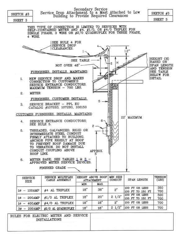
57
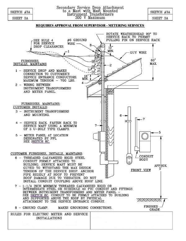
58
ELECTRIC POLICY INTRODUCTION CHAPTER I GENERAL
 INTRODUCTION This policy has been adopted by the Board of Public Works as a guide to obtaining electric service and to set forth the services available, conditions for service, and standards for materials
RESIDENTIAL SUBDIVISION SERVICE REQUIREMENTS SECTION VI RESIDENTIAL SUBDIVISION SERVICE REQUIREMENTS
 SECTION VI SERVICE REQUIREMENTS This section discusses the requirements for establishing electric service to new residential subdivisions in Palo Alto. Subdivisions are normally constructed on dedicated
GENERAL INFORMATION 1.01 PURPOSE
 GENERAL INFORMATION 1.01 PURPOSE The purpose of this manual is to supply essential information to customers, employees, architects, engineers, contractors, and others concerned with electrical installations
7. Residential Single-Family and Duplex Buildings (Dwellings)
") Sin g le -F a mily a n d Du p le x Bu ild in g s 2016 Electric Service Requirements, 2 nd Edition Section 7 Section 7 Residential Single-Family and Duplex Buildings (Dwellings) Directory Page 7.1 General
Sin g le -F a mily a n d Du p le x Bu ild in g s 2016 Electric Service Requirements, 2 nd Edition Section 7 Section 7 Residential Single-Family and Duplex Buildings (Dwellings) Directory Page 7.1 General
Metering and Service Installation:
 Table of Contents 1. Metering Installation Requirements, General... 1 2. Type of Service... 2 3. Definitions... 2 4. Who Provides Metering Equipment?... 2 5. Establishment of Service... 2 6. Meter Access...
STOUGHTON UTILITIES ELECTRIC SERVICE RULES AND INFORMATION
 CHAPTER 1 - GENERAL INFORMATION 100. Purpose 101. Codes and rules 102. Continuity of service 103. Frequency, Voltage, and Amperage Limitations 104. High voltages 105. Unusual capacity requirements 106.
10 Commercial, Industrial, Agricultural Services
 10 Commercial, Industrial, Agricultural Services This section describes the Power Company requirements for commercial, industrial, and agricultural services. This section covers single phase and three
AMENDMENT ELECTRIC SERVICE MANUAL 2014
 AMENDMENT (Pages 20,43,50,72,74,,76,78,83,86,99) ELECTRIC SERVICE MANUAL 2014 Effective April 1, 2015 18-7 6.0 SERVICE AND SERVICE ENTRANCES (General), Continued Conductor Sizing It is recommended that
ENTRANCE EQUIPMENT ER D PAGE 1 OF 5
 PAGE 1 OF 5 USE: Requirements for entrance equipment. PREVIOUS REVISION 07-01-98 ORIGINATED 03-94 PREVIOUS NUMBER ER 100 (12-01-81) LATEST REVISION: Updated meter socket labeling specification and instrument
7 Single Family Service
 7 Single Family Service 7. General The location of the service entrance on the Customer s premises is an important consideration. For clearance and location information see section 5 (Clearances). Consult
Installing or Rebuilding Your Electric Service
 Installing or Rebuilding Your Electric Service 2 3 Contents Policies for New and Rebuilt Electric Service 2-4 Paperwork and fees...2 Five-year policy...3 Proposed route location and conditions...3 Construction
TABLE OF CONTENTS. Important Notices Underground Plant Protection Information. Commercial/Industrial Information Sheet
 DRAWING NUMBER INTRODUCTORY INFORMATION Important Notices Underground Plant Protection Information Code Clearances Commercial/Industrial Information Sheet Work Management Customer Projects Engineering
RESIDENTIAL UNDERGROUND AND OVERHEAD SERVICE REQUIREMENTS SECTION II RESIDENTIAL UNDERGROUND AND OVERHEAD SERVICE REQUIREMENTS
 SECTION II This section discusses the City of Palo Alto's requirements for establishing electric service to new or upgraded residential installations. The same requirements apply to both underground and
ELECTRIC DIVISION RULES AND PROCEDURES FOR ELECTRIC SERVICE
 Public Works and Utilities 1250 N. Highland St. Mount Dora, FL 32757 352-735-7151 ext. 1805 Fax: 352-735-1539 E-mail: publicworks@cityofmountdora.com ELECTRIC DIVISION RULES AND PROCEDURES FOR ELECTRIC
Section 6 Electric Metering: Residential
 Section 6 Electric Metering: Residential 6.1. Scope This section provides specific information for residential metering that is not covered by the basic requirements in Section 5, Electric Metering: General.
Requirements for Secondary Voltage Revenue Metering (750 V and less)
") Requirements for Secondary Voltage Revenue Metering (750 V and less) To view the latest revision of this document go to: http://www.bchydro.com/ext/metering/ January 28, 2010 Copyright 2008 by BC Hydro.
Requirements for Secondary Voltage Revenue Metering (750 V and less) To view the latest revision of this document go to: http://www.bchydro.com/ext/metering/ January 28, 2010 Copyright 2008 by BC Hydro.
SPECIFICATIONS FOR RESIDENTIAL CONSTRUCTION
 Roseville Electric SPECIFICATIONS FOR RESIDENTIAL CONSTRUCTION REVISED 04/25/18 Specifications for Residential Construction Revision List REVISION Date Page No. Description 03/20/00 6.1-6.2 Added Armorcast
10. METERING General Requirements
 10. METERING 10.1 General Requirements A. The Company will not supply service to a Customer whose wiring is designed for resale of electricity through submetering except for recreational campgrounds, marinas,
SERVICE ATTACHMENT ON A BUILDING WITH BUS DUCT SERVICE ENTRANCE AND INDOOR METERING
 SERVICE ATTACHMENT ON A BUILDING WITH BUS DUCT SERVICE ENTRANCE AND INDOOR METERING Obtain acceptance and specific details from the local Company office. 1. Service entrance duct (see Note 1). Company
2. DEFINITIONS. 2.3 APPROVED Acceptable to the authority enforcing the National Electric Code
 2. DEFINITIONS 2.1 ACCEPTABLE Acceptable to the Company. 2.2 ADVANCED METER A meter that is capable of remote reading, and is capable of storing electric consumption data at specified time intervals of
For Conduit Inspections
 Underground Conduit Standards - Table of Content 5/8/2017 Section S22 Underground Conduit Standard Index: Description: 00 Table of Content 01 General Notes 02 Definition of Terms 03 Primary Riser Conduit
Engineering Rules and Regulations for Electric Service Platte-Clay Electric Cooperative, Inc.
 Engineering Rules and Regulations for Electric Service Platte-Clay Electric Cooperative, Inc. December 2016 (Expires 9/30/18) Kearney Cooperate Headquarters 1000 W. 92 Highway Kearney, MO Platte City District
The cost estimation methodology used to update the charges and credits is the same methodology the Company utilized in the prior year s filing.
 LISA D. NORDSTROM Lead Counsel lnordstrom@idahopower.com December 28, 2018 Public Utility Commission of Oregon Filing Center 201 High Street SE, Suite 100 P.O. Box 1088 Salem, Oregon 97301 Re: Tariff Advice
Approved Meter Sockets and Cabinets
 Single Unit Residential Guide 1 PHASE, 120/240 VOLT SERVICES SERVICE CAPACITY OWNED METERING (Metering sockets and cabinets are supplied by Customer). Outdoor meter mounting height is 1730 mm ( 5 8 ) to
SPECIFICATIONS FOR RESIDENTIAL CONSTRUCTION
 Roseville Electric SPECIFICATIONS FOR RESIDENTIAL CONSTRUCTION REVISED 10/03/17 Specifications for Residential Construction Revision List REVISION Date Page No. Description 8/18/09 T.O.C., 8.1-8.1.5 &
INTERCONNECTION STANDARDS FOR CUSTOMER-OWNED GENERATING FACILITIES 25 kw OR LESS PUBLIC UTILITY DISTRICT NO. 1 OF CHELAN COUNTY
 INTERCONNECTION STANDARDS FOR CUSTOMER-OWNED GENERATING FACILITIES 25 kw OR LESS PUBLIC UTILITY DISTRICT NO. 1 OF CHELAN COUNTY Table of Contents Chapter 1. Purpose and scope. Pg 3 Chapter 2. Application
9. Non-Residential Services (Commercial, Industrial, and Agricultural)
") Section 9 2016 Electric Service Requirements, 3rd Edition Section 9 Non-Residential Services Directory Page 9.1 General Requirements 68 9.2 Direct-Connect Metering, Single Installations 69 9.3 Direct-Connect
Section 9 2016 Electric Service Requirements, 3rd Edition Section 9 Non-Residential Services Directory Page 9.1 General Requirements 68 9.2 Direct-Connect Metering, Single Installations 69 9.3 Direct-Connect
WELLS RURAL ELECTRIC COMPANY Adopted: March 1976 Revised: March 21, 2017 Reviewed: August 21, 1998 RULE NO. 2
 WELLS RURAL ELECTRIC COMPANY Adopted: March 1976 Revised: March 21, 2017 Reviewed: August 21, 1998 DESCRIPTION OF SERVICE A. General: RULE NO. 2 1. Alternating current service at 60-hertz (cycles per second)
1. General Requirements
 Ge n e ra lre q u ire me n ts 2016 Electric Service Requirements, 3rd Edition Section 1 Section 1 General Requirements Directory Page 1.1 Manual Purpose and Scope 1 1.2 Customer and Power Company Defined
BRYAN ELECTRIC DEPARTMENT General Rules and Regulations. Bryan Municipal Utilities 841 E. Edgerton St. Bryan, OH (419)
") BRYAN ELECTRIC DEPARTMENT General Rules and Regulations Bryan Municipal Utilities 841 E. Edgerton St. Bryan, OH 43506 (419) 633-6100 1 Table of Contents Section Page 1. General 3 2. Applicability, General
BRYAN ELECTRIC DEPARTMENT General Rules and Regulations Bryan Municipal Utilities 841 E. Edgerton St. Bryan, OH 43506 (419) 633-6100 1 Table of Contents Section Page 1. General 3 2. Applicability, General
Residential Application for New Electric Service
 Attn: Engineering Department 42 Wescom Rd Johnson VT 05656 1-800-832-2667 ext. 1171 802-635-2331 ext. 1171 802-635-4210 fax Residential Application for New Electric Service INVOICE Attn: Engineering Department
Electric Service Rule No. 2 Description of Service
 Page 1 of 6 A. General 1. All electric service described in this Rule is subject to conditions in the applicable Rate Schedule, other pertinent Rules, and the Electric Service Guides. 2. Alternating-current
COMMERCIAL QUICK REFERENCE
 COMMERCIAL QUICK REFERENCE PROVO CITY POWER STANDARDS ELECTRICAL ENGINEERING UPDATED: 2016 SPECIFICATIONS SUBJECT TO CHANGE WITHOUT NOTIFICATION. 18" MIN. OF TAIL. (NEUTRAL CONDUCTOR MUST BE WHITE OR
Published 2018 RULES AND REGULATIONS FOR ELECTRIC SERVICE
 Published 2018 RULES AND REGULATIONS FOR ELECTRIC SERVICE TABLE OF CONTENTS Page No. SECTION I INTRODUCTION 1 A. PURPOSE 1 B. SCOPE 1 C. CORPORATION 1 D. CODES 1 E. RESPONSIBILITY 1 F. INSPECTION 2 G.
KAUAI ISLAND UTILITY COOPERATIVE KIUC Tariff No. 1 Lihue, Kauai, Hawaii Original Sheet 5 RULE NO. 2 CHARACTER OF SERVICE
 Lihue, Kauai, Hawaii Original Sheet 5 RULE NO. 2 A. GENERAL 1. The character of service available at any particular location must be ascertained by the Company business office, and will depend upon the
KIUC Service Installation Manual
 KIUC Service Installation Manual Second Edition (November 2016) This manual provides the general requirements for electric service and metering for Kauaʻi Island Utility Cooperative ("KIUC") and is meant
2008 Guidebook of Requirements. for Electric Service
 2008 Guidebook of Requirements for Electric Service TABLE OF CONTENTS 1. General Information... 1 1.1 Introduction... 1 1.2 Policies & Procedures... 1 1.3 Safety...2 1.4 Electrical Codes...2 1.5 Effective
201 S. Anaheim Blvd. Page No Anaheim, CA RULE NO. 2 DESCRIPTION OF SERVICE
 201 S. Anaheim Blvd. Page No. 3.2.1 A. GENERAL 1. The character of electric service available at any particular location should be ascertained by inquiry at the City's Electrical Engineering Division office.
ELECTRIC SERVICE RULES UTILITY/CATV SERVICES Issued Jan 2016
 UTILITY/CATV SERVICES CHAPTER 9 900. GENERAL A. Alliant Energy receives many requests for electric service from other utilities; telephone, telecommunications companies, cable television, the Department
RULES AND REGULATIONS FOR ELECTRIC SERVICE
 RULES AND REGULATIONS FOR ELECTRIC SERVICE PUBLISHED 1993 TABLE OF CONTENTS SECTION I INTRODUCTION... 5 1. PURPOSE... 5 2. SCOPE... 5 3. COOPERATION... 5 4. CODES... 5 5. RESPONSIBILITY... 5 6. INSPECTION...
UNS Electric, Inc. Rules and Regulations
 Original Sheet No.: 902 A. In these, the following definitions will apply unless the context requires otherwise: 1. Actual Cost: The cost incurred by the Company for labor, materials and equipment including
AUSTIN UTILITIES. CHARACTER OF SERVICE: AC, 60 cycles, 120/240 Volt, three wire, single-phase; or 120 Volt, two wire.
 AVAILABLE: Within established City Limits. AUSTIN UTILITIES Schedule (110) Issued 11/12/13 Supersedes (110) Issued 11/13/12 Sheet No. 1 of 1 RESIDENTIAL SERVICE APPLICABLE: To single-family residences
A member-consumer with a QF facility shall not participate in the Cooperative s electric heat rate program.
 Electric Tariff _2nd Revised Sheet No. 72 Filed with Iowa Utilities Board Cancels _1st Sheet No. _72 Cooperative is a member of Central Iowa Power Cooperative (CIPCO), a generation and transmission cooperative
PERMANENT RESIDENTIAL UNDERGROUND SERVICE
 CITY OF RICHLAND ENERGY SERVICES DEPARTMENT 505 Swift Boulevard, MS-21 Richland, WA 99352 Telephone (509) 942-7403 Fax (509) 942-7405 PERMANENT RESIDENTIAL UNDERGROUND SERVICE A. INTRODUCTION This guide
Application for Service Residential Subdivision / Development
 Application for Service Residential Subdivision / Development Please complete this application and submit the completed form and attachments to PG&E Application for Service at P.O. Box 24047 Fresno CA
Table of Contents. Electrical Service Requirements. 1. General Requirements
 Table of Contents 1. General Requirements 1.1 General Definition.................................................... 1 1 1.2 Booklet Purpose and Organization....................................... 1-1
Commercial Electric Policy
 Commercial Electric Policy 7/19/16 1 Table of Contents General Information..3 Construction.3 Ownership.4 Multi-Unit/Multi-Service Buildings....4 Secondary Termination Enclosures.4 Meter Bases.5 Temporary
Pentahead bolts See note 2. Conduit run as specified. Company facility. Refer to drawing SS8.6-2 or SS8.6-3 STANDARD SERVICE INSTALLATION
 PULL BOX F SECONDARY SYSTEM Typical grade Pentahead bolts See note 2 Conduit run as specified Plastic or fiberglass for grass areas or Polymer concrete for light duty areas (see notes 2, 3, & 4) Company
TEMPORARY ELECTRICAL SERVICE
 ENERGY SERVICES ENGINEERING 840 Northgate Drive Telephone (509) 942-7403 Fax (509) 942-7405 P.O. Box 190 Richland, WA 99352 www.ci.richland.wa.us/energyservices TEMPORARY ELECTRICAL SERVICE A. INTRODUCTION
COMMERCIAL HANDBOOK 2013 EDITION MATANUSKA ELECTRIC ASSOCIATION, INC. PALMER, ALASKA
 COMMERCIAL HANDBOOK 2013 EDITION MATANUSKA ELECTRIC ASSOCIATION, INC. PALMER, ALASKA ~ &teauea~. 'l«e. PtUt tjutee a'~ 2929 Pa/mete. Ata414 99645. ~~/7
Panola-Harrison Electric Cooperative, Inc. Louisiana Tariff Effective: March 3, 2004
 Rate Schedule: R Page 1 of 1 RESIDENTIAL RATE SCHEDULE R Available in all territory served by the Cooperative, in accordance with the established rules and regulations of the Cooperative. Residential uses
Associated equipment As related to metering equipment: such as the current transformers, CT wiring and test switches.
 APPENDIX Glossary Approval Acceptable to the authority having jurisdiction. Assessor s Parcel Number (APN) Identifying number assigned by the county assessor s office to each taxable building lot in the
RESIDENTIAL NEW CONSTRUCTION PACKET CITY OF VERO BEACH UTILITIES. Important Notice to Builders/Contractors/Developers From Electrical Engineering
 1036 20 TH ST. PO BOX 1389 VERO BEACH, FLORIDA 32961-1389 TELEPHONE: (772) 978-5100 FAX: (772) 978-5125 Important Notice to Builders/Contractors/Developers From Electrical Engineering You must contact
Electric Service and Meter Installations Manual SCANA Corporation 2018
 Electric Service and Meter Installations Manual SCANA Corporation 2018 Revised: January 2018 On file with South Carolina Public Service Commission Table of Contents Section 1: Introduction Customer Call
57. Line Extensions Policy 1: Individual Residential Customers
 Page 1 of 36 NHPUC NO. 20 - ELECTRICITY DELIVERY Original Page 57 LIBERTY UTILITIES Line Extensions Policy 1: Individual Residential Customers 57. Line Extensions Policy 1: Individual Residential Customers
UNDERGROUND SERVICES - SECONDARY
 UNDERGROUND SERVICES - SECONDARY Contents - Underground Services... U-1 General Requirements for Underground Service...U-2 Names of Parts for Underground Service... U-3 Service Termination in a Service
See NT POWERCOS , Classification Based On Service Size.
 Newmarket-Tay Power Distribution Ltd. Conditions of Service Number: NT POWER COS 310 01 Issue Date: July, 2007 Next Review Date: February, 2020 Residential 1. Preamble This section covers all items that
2017 EDITION. Guidebook of Requirements for Electric Service
 2017 EDITION Guidebook of Requirements for Electric Service TABLE OF CONTENTS 1. General Information...1 1.1 Introduction...1 1.2 Policies & Procedures...1 1.3 Safety...1 1.4 Electrical Codes...2 1.5 Effective
PUBLIC UTILITY DISTRICT NO. 1 OF CHELAN COUNTY
 Fees and Charges PUBLIC UTILITY DISTRICT NO. 1 OF CHELAN COUNTY 1 SECTION TABLE OF CONTENTS Fees and Charges PAGE TABLE OF CONTENTS... 2 DELEGATED AUTHORITY... 3 ELECTRICAL FEES AND CHARGES... 4 SERVICE
CONTENTS BY CHAPTER. Chapter 2: COMPANY EQUIPMENT ON CUSTOMER PREMISES
 CONTENTS BY CHAPTER Chapter 1: GENERAL INFORMATION Chapter 2: COMPANY EQUIPMENT ON CUSTOMER PREMISES Chapter 3: SERVICE ENTRANCES Chapter 4: METERING INSTALLATION Chapter 5: CUSTOMER-INSTALLED SERVICE
Access Management Standards
 Access Management Standards This section replaces Access Control Standards on Page number 300-4 of the Engineering Standards passed February 11, 2002 and is an abridged version of the Access Management
New Service. From... BARRON. Spooner Office: P.O. Box 261 Spooner, WI Barron Office: P.O. Box 40 Barron, WI
 New Service Guidelines and Diagrams From... BARRON www.barronelectric.com email: janderson@barronelectric.com Barron Office: P.O. Box 40 Barron, WI 54812-0040 Spooner Office: P.O. Box 261 Spooner, WI 54801-0261
Customer Guide to Electric Service Requirements
 Customer Guide to Electric Service Requirements Tillamook People s Utility District Power Services Group 1115 Pacific Avenue Tillamook, Oregon 97141 OFFICE: 503.815.8629 FAX: 503.815.8648 TOLL FREE: 800.422.2535
REQUIREMENTS FOR PARALLEL OPERATION FOR CUSTOMERS WITH GENERATION NOT EXCEEDING 50 kw
 REQUIREMENTS FOR PARALLEL OPERATION FOR CUSTOMERS WITH GENERATION NOT EXCEEDG 50 kw FOREWARD Requirements for Parallel Operations for Customers with Generation Not Exceeding 50 kw is intended to be used
Electric Service Requirements
 Electric Service Requirements for Residential & Commercial Service Committed to safely and economically provide reliable energy and other services which bring value to its membership. ELECTRIC SERVICE
ROCHESTER PUBLIC UTILITIES
 ROCHESTER PUBLIC UTILITIES ELECTRIC SERVICE RULES AND REGULATIONS Revised August 2011 INTRODUCTION Rochester Public Utilities (hereafter referred to as RPU) has assembled this booklet to assist its customers
Revised Cal. P.U.C. Sheet No E Cancelling Revised Cal. P.U.C. Sheet No E
 Revised Cal. P.U.C. Sheet No. 33883-E Cancelling Revised Cal. P.U.C. Sheet No. 28182-E ELECTRIC SCHEDULE LS-2 Sheet 1 APPLICABILITY: TERRITORY: RATES: This schedule is applicable to services for lighting
Customer Installation Standards for Electric Service
 Customer Installation Standards for Electric Service Effective June 1, 2008 A transition period will exist from June 1 through December 31, 2008 in which installations may be approved and connected as
Approved Contractor Construction e-guide Residential Commercial
 Approved Contractor Construction e-guide Residential Commercial Clark Public Utilities PO Box 8900 Vancouver, WA 98668 (PAGE 2) TABLE OF CONTENTS PAGE Trenching 3 Wire 8 Single-Phase Transformer Set 13
Indianapolis Power & Light Company
 Indianapolis Power & Light Company Electric Service and Meter Manual The Electric Service & Meter Manual is not copyrighted and permission is hereby given to reproduce this document. However, the Indianapolis
Please Refer to Attached Sample Form
 Pacific Gas and Electric Company San Francisco, California U 39 Revised Cal. P.U.C. Sheet No. 32105-E Cancelling Revised Cal. P.U.C. Sheet No. 28313-E Electric Sample Form No. 62-0686 Application for Service
SINGLE PHASE WIRING SPECIFICATIONS
 SINGLE PHASE WIRING SPECIFICATIONS 1-866-MEC-ELEC (1-866-632-3532) Office Locations: Hondo Office 237 Hwy 173 N Hondo, TX 78661-0370 Fax 830.426.3335 Dilley Office 1718 W. FM 117 Dilley, TX 78017 Fax 830.965.1425
Electric Service Guidelines TSN
 Electric Service Guidelines TSN 449260 May 2017 Important Notice Regarding Removal of Oncor Electric Delivery Company LLC Meters to Perform Work on Customer s Premise Effective October 15, 2013, as provided
CITY OF BOWLING GREEN, OHIO MUNICIPAL UTILITIES ELECTRIC RATE SCHEDULES
 MUNICIPAL UTILITIES S BOARD OF PUBLIC UTILITIES WILLIAM CULBERTSON MIKE FROST JOYCE KEPKE JOHN MEKUS MEGAN NEWLOVE MAYOR RICHARD A. EDWARDS MUNICIPAL ADMINISTRATOR JOHN S. FAWCETT UTILITIES DIRECTOR BRIAN
Specifications and Requirements for Electric Installations
 Specifications and Requirements for Electric Installations Effective August 2015 Directory of Company Offices Directory of Company Offices Upper Hudson Division Catskill Office 7964 Route 9W Catskill,
Louisville Gas and Electric Company
 P.S.C. Electric No. 11, Original Sheet No. 57 APPLICABLE In all territory served. AVAILABILITY OF SERVICE Available to any customer-generator who owns and operates a generating facility located on Customer
SECTION VII METERING INSTALLATIONS
 SECTION VII METERING INSTALLATIONS 1. GENERAL Outdoor metering is required for all new service installations to one, two, and three family detached, semi-detached and row houses. 2. COMPANY FURNISHES AND
City of Banning Electric Utility - Residential Self Generating Facility Program (Photovoltaic Systems <48kW)
") City of Banning Electric Utility - Residential Self Generating Facility Program (Photovoltaic Systems
City of Banning Electric Utility - Residential Self Generating Facility Program (Photovoltaic Systems
Meter Installation. -and- Padmount Transformer Guide
 Meter Installation -and- Padmount Transformer Guide Feb. 2016 METERING REQUIREMENTS The following information shall be used as a guide for installing metering equipment. A self-contained meter has all
REQUIREMENTS FOR A RESIDENTIAL STRUCTURE TO BE CONSIDERED A PERMANENT INSTALLATION
 REVISIONS (Note: All pages have been renumbered) Section 2.0 DEFINITIONS Removed the reference to the State of Ohio in the definition of COMPANY and also removed the reference to the State of Ohio throughout
Electric Service Requirements
 Electric Service Requirements Section V Commercial Industrial July 2007 ENGINEERING SPECIFICATION 620 S Street, P.O. Box 5830, Sacramento, CA 95852-830 The Power To Do More ṢM SM A registered service mark
SECTION 300 OVERHEAD SERVICE
 SECTION 300 OVERHEAD SERVICE 300.01 General Company provides, installs, and maintains service drop to point of delivery approved by Company. Customer provides point of attachment which is acceptable to
All territory within the incorporated limits of the City and land owned or leased by the City.
 A. APPLICABILITY: This schedule applies to all connections, expansions, and upgrades to the City's Electric Distribution System except those that serve street lighting or traffic signals. B. TERRITORY:
TERMS AND CONDITIONS
 XXV. NET METERING A. Applicability and Availability 1. The terms Net Metering Service, Demand Charge-based Time-of- Use Tariff, Net Metering Customer, Customer, Time-of-Use Customer, Time-of-Use Tier,
3.1 Overview of ATCO Electric s URD System Design
 Page: 3-1 3.0 URD DESIGN GUIDELINES 3.1 Overview of ATCO Electric s URD System Design The power supply to all single lot underground residential services is through front lot service. Single phase transformers
Columbia Water & Light Interconnection & Net Metering Agreement Electrical Facility
 Processed Date Columbia Water & Light Interconnection & Net Metering Agreement Electrical Facility Customer s Printed Name Installation Street Address Account Number Please note: Columbia Water & Light
THREE PHASE WIRING SPECIFICATIONS
 THREE PHASE WIRING SPECIFICATIONS 1-866-MEC-ELEC (1-866-632-3532) Office Locations: Hondo Office 237 Hwy 173 N Hondo, TX 78661-0370 Fax 830.426.3335 Dilley Office 1718 W. FM 117 Dilley, TX 78017 Fax 830.965.1425
Please Refer to Attached Sample Form
 Pacific Gas and Electric Company San Francisco, California U 39 Revised Cal. P.U.C. Sheet No. 32104-E Cancelling Revised Cal. P.U.C. Sheet No. 28312-E Electric Sample Form No. 62-0685 Application for Service
Member Installation Standards for Electric Service
 Member Installation Standards for Electric Service June 2014 Edition This document is not copyrighted. Copying is encouraged. Contents Section 1: Foreword, General Information, and Terms...6 1.1 Purpose...
Contents. 1 Introduction. 2. Advisory and Information Systems. 3. Supply. 3.1 Quality of Electric Supply. 3.2 Interference with other Customers
 DISTRIBUTION CODE Contents 1 Introduction 2. Advisory and Information Systems 3. Supply 3.1 Quality of Electric Supply 3.2 Interference with other Customers 3.3 Application for the Supply of Electricity
SECTION 3 CUSTOMER CLASS SPECIFIC
 SECTION 3 CUSTOMER CLASS SPECIFIC 3.0 General PowerStream shall recover costs associated with the installation of Connection Assets, by customer class, via a Basic Connection Charge and a Variable Connection
Commercial Electric Service Handbook
 Commercial Electric Service Handbook January 2011 CONTACTS Clark Public Utilities: Website........................................... www.clarkpublicutilities.com Construction Services department (To initiate
TEMPORARY ELECTRIC WIRING FOR CARNIVALS, CONVENTIONS, EXHIBITIONS, FAIRS AND SIMILAR USES
 INFORMATION BULLETIN / PUBLIC - ELECTRICAL CODE REFERENCE NO.: LAMC 93.0230 Effective: 3-24-69 DOCUMENT NO. P/EC 2002-006 Revised: 11-17-00 Previously Issued As: RGA #7-69 TEMPORARY ELECTRIC WIRING FOR
CITY OF BOWLING GREEN, OHIO MUNICIPAL UTILITIES ELECTRIC RATE SCHEDULES
 MUNICIPAL UTILITIES S BOARD OF PUBLIC UTILITIES AMY CRAFT-AHRENS WILLIAM CULBERTSON MIKE FROST MEGAN NEWLOVE MATT PAQUETTE MAYOR RICHARD EDWARDS MUNICIPAL ADMINISTRATOR LORI TRETTER UTILITIES DIRECTOR
A. Submit manufacturer's literature and technical data before starting work.
 SECTION 16425 SWITCHBOARD PART 1 GENERAL 1.01 SUMMARY A. Related Section: 1. 16450 - Grounding. 1.02 SUBMITTALS A. Submit manufacturer's literature and technical data before starting work. B. Submit Shop
SECTION ENCLOSED SWITCHES AND CIRCUIT BREAKERS
 SECTION 26 28 16 ENCLOSED SWITCHES AND PART 1 - GENERAL 1.1 SUMMARY A. Section includes the following individually mounted, enclosed switches and circuit breakers rated 600V AC and less: 1. Fusible switches.
Electric Service Requirements & Guidelines
 Electric Service Requirements & Guidelines Montana Service Area September 2011 NORTHWESTERN ENERGY Montana Service Area ELECTRIC SERVICE REQUIREMENTS AND GUIDELINES CONTENTS I. GENERAL INFORMATION 1.01
d/b/a EVERSOURCE ENERGY Cancels M.D.P.U. No. 44 STREET AND SECURITY LIGHTING RATE S-1
 Page 1 of 10 AVAILABILITY Street and security lighting services are available under this rate to public authorities for street, highway, bridge, parkway and adjacent area lighting and flood lighting. Area
A. This Section includes Low Voltage Switchgear Work, as indicated on the drawings, and as specified herein.
 16425 SWITCHBOARD ************************************************************************************************************* SPECIFIER: CSI MasterFormat 2004 number: 26 24 13 An optional keynote to
M.P.S.C. No. 2 Electric Ninth Revised Sheet No. 50 (Rate Case) Cancels Eighth Revised Sheet No. 50
 Cancels Eighth Revised Sheet No. 50") WI WISCONSIN ELECTRIC POWER COMPANY M.P.S.C. No. 2 Electric Ninth Revised Sheet No. 50 (Rate Case) Cancels Eighth Revised Sheet No. 50 CLASS OF SERVICE: INCANDESCENT STREET LIGHTING FULL REQUIREMENTS SERVICE
WI WISCONSIN ELECTRIC POWER COMPANY M.P.S.C. No. 2 Electric Ninth Revised Sheet No. 50 (Rate Case) Cancels Eighth Revised Sheet No. 50 CLASS OF SERVICE: INCANDESCENT STREET LIGHTING FULL REQUIREMENTS SERVICE