ISB6.7 CM2350 B101 for School Bus Applications
|
|
|
- Colin Daniel
- 6 years ago
- Views:
Transcription


1 ISB6.7 CM2350 B101 for School Bus Applications 2014
2 Source Of The Engine Name The ISB6.7 CM2350 B101 engine names are derived from many sources: The IS portion of the name represents the Interact System. The Interact System is Cummins automotive/on-highway full-authority electronic engine control system. The B portion of the name represents the engine family. The ISB is part of the B series mid-range engine family. The 6.7 portion represents the engine displacement. The CM2350 portion of the name represents the engine control system. The B101 suffix means that this engine equipped with EPA 2013 On-Board Diagnostics (OBD) and following aftertreatment hardware: Exhaust Gas Recirculation (EGR) Aftertreatment Outlet NOx Sensor Diesel Oxidation Catalyst (DOC) Aftertreatment Diesel Particulate filter (DPF) Aftertreatment Diesel Exhaust Fluid (DEF) Quality Sensor Integrated Aftertreatment Dosing Control Unit Aftertreatment Airless Selective Catalytic Reduction (SCR) Aftertreatment intermediate NH3 Sensor Aftertreatment Outlet NOx Sensor
3 Base Engine Specifications: The ISB6.7 CM2350 is a 6.7 liter displacement inline 6 cylinder engine. Firing order: Rear gear train only Engine operation voltage 12 V and 24 volts. All required components are available in 12 and 24 volts: CM2350 ECM Grid heaters Aftertreatment NOx Sensors VGT actuator DEF Supply Module Starter, Alternator
4 Base Engine Specifications: Model, BHP, Peak Torque Governed RPM School Bus Applications ISB ISB ISB ISB ISB ISB ISB

5 Engine Dataplate Location And Information: The dataplate contains the following information: Engine serial number, Control parts list (CPL), Model, Horsepower and rpm rating. If the engine dataplate is not readable, the engine serial number can be identified on the engine block on top of the lubricating oil cooler housing. Additional engine information is available by reading the ECM dataplate.
6 Engine Quick Identifiers: The CM2350 ECM with two connectors: A ninety six pin Engine harness connector A ninety six pin OEM harness connector Aftertreatment System: New aftertreatment system sensors Aftertreatment Intermediate NH3 Sensor Diesel Exhaust Fluid (DEF) Quality Sensor (Optional) Datalinked Temperature Sensors Dosing Control Module eliminated (Integrated with CM2350 ECM) Air Handling New intake air throttle New programmable turbocharger actuator


7 Engine Systems The following sections will cover the systems and components of the engines including: Mechanicals Air system Cooling system Lubrication system Fuel system
8 8 MECHANICALS


9 Front Gear Cover The front gear cover houses the lubricating oil pump, front crankshaft seal, and camshaft speed indicator ring. The front gear covers also contains the oil pressure switch, camshaft speed/position sensor, and crankshaft speed/position sensor. 9

10 Front Crankshaft Seal The front crankshaft seal is a dual or non-lip style seal which utilize a built in wear sleeve and a concealed sealing lip. Because the rotating portion of the seal does not contact the crankshaft, wear will not occur at the crankshaft but instead internal to the seal. No wear sleeve or oversize front crankshaft seal is available 10


11 Crankshaft Seal, Front - Install 11 Use tool, Part Number , to install the oil seal into the front gear cover. Mount the replacer screw assembly onto the crankshaft nose. Install the two M12 x 1.25 x 60 mm socket head capscrews. Place the new front crankshaft seal over the crankshaft nose and slide it by hand toward the front gear cover as far as possible. NOTE: Make sure the seal is positioned square with the crankshaft. While holding the replacer screw, install the crankshaft seal replacer onto the replacer screw assembly. Advance the crankshaft seal replacer toward the seal by rotating it clockwise until it is positioned against the seal. While holding the crankshaft seal replacer, rotate the replacer screw counterclockwise until the crankshaft seal replacer contacts the front gear cover.

12 Rear Crankshaft Seal Lip-style rear crankshaft seal 12

 One for Rear Gear Train Engine (2) The")

13 Rear Crankshaft Seal - Continued Each new rear crankshaft seal will come with 2 disposable seal drivers One for Front Gear Train Engine (1) One for Rear Gear Train Engine (2) The rear crankshaft seal is installed in the flywheel housing bore, 2 installation methods available 13


14 Rear Crankshaft Seal - Install Rear Crankshaft Seal Replacer Kit, Part # Part # Description Q-ty Replacer screw assembly Crankshaft seal replacer Socket head capscrew, M12 x 1.25x 25 mm Sheet metal screw, Number 10x25.4 mm [1 in] long Disposable plastic driver (purchased with rear crankshaft seal kit)


15 15 Rear Gear Train

16 Vibration Damper and Crankshaft Speed Indicator Ring Viscous damper is standard Vibration damper and crankshaft speed indicator ring are a permanent assembly When either damaged replace as assembly 16


17 17 Rocker Levers Mounted on a common rocker shaft Receives pressurized oil for lubrication from a drilling in the rocker shaft Each rocker lever actuates two valves by the crosshead Each rocker lever has two drillings: One drilling supplies lubrication oil to the push rod Other drilling supplies lubrication oil to e-foot

18 18 Crosshead Same as used on all 4 valve per cylinder B product The crosshead allows the rocker lever to move both exhaust or intake valves at the same time. The crosshead receives its lubrication from a drilling in the rocker lever and rocker shaft


19 19 Overhead Set Overhead setting is only required at the interval specified in the appropriate Operation and Maintenance / Owners manuals, or, When engine repairs cause removal of the rocker levers and/or loosening of the adjusting screws.


20 20 Overhead Set TDC 1 1I, 1E, 2I, 3E, 4I, and 5E. TDC 6 2E, 3I, 4E, 5I, 6I, and 6E. Intake Exhaust in in
 Three pass through connectors in rocker housing Three small wiring harnesses connect passthrough connectors to injectors 21")
21 Rocker Lever Housings Two options: Standard (rocker cover mounted breather) Features two electrical connectors Connectors are part of the rocker cover gasket Low Clearance (flywheel mounted breather) Three pass through connectors in rocker housing Three small wiring harnesses connect passthrough connectors to injectors 21
 Crankcase")

22 22 Rocker Lever Cover Crankcase Breather mounted in the rocker cover Same as used on many current increased displacement ISB series product Has a permanently attached breather baffle (1) Crankcase gases exist at the rear of the rocker lever cover and enter the crankcase breather tube Solids/liquids drain back into the crankcase through a tube connecting the breather to the top of the rear-gear housing


23 Open Crankcase Breather System Consists of a housing, breather element, and drain tubes Maintenance: 2,500 hrs or 75,000 miles 23
24 AIR INTAKE AND EXHAUST SYSTEM

25 Air Intake Diagram 25


26 Air Intake Connection Two drillings for easier cleaning Change made on 2010 product Same Differential pressure sensor for B & L

27 ENGINE INTAKE THROTTLE ACTUATOR Intake throttle actuator is used on the midrange engines provides better air control for EGR mixing The ITA acts as an EGR assist device to reduce pumping losses to EGR flow and exhaust restriction Allows for greater optimization of engine timing. Closing the ITA limits the intake (boost) air and reduces the pressure the EGR flow works against ITA closes when EGR and VGT are not capable of providing the commanded EGR flow without assistance 27
 and fully closed (0")

28 ENGINE INTAKE THROTTLE ACTUATOR Actuator controls the movement of the throttle plate. The position of the engine intake throttle actuator moves between fully open (100 percent) and fully closed (0 percent). Normally Open / Spring Loaded Expected Actuator Position At key off 100 % At engine start - 90 % While the engine is running, the engine intake throttle actuator should never be fully open (100 %) Actuator position could be monitored with INSITE

29 ENGINE INTAKE THROTTLE ACTUATOR - Codes Actuator Codes Electronic Throttle Control Actuator Driver Circuit - Voltage above normal, or shorted to high source Electronic Throttle Control Actuator Driver Circuit - Voltage below normal, or shorted to low source Electronic Throttle Control Actuator - Mechanical system not responding or out of adjustment Position Sensor Codes Engine Intake Throttle Actuator Position Sensor Circuit - Voltage above normal, or shorted to high source Engine Intake Throttle Actuator Position Sensor Circuit - Voltage below normal, or shorted to low source Engine Intake Throttle Actuator Position Sensor - Data erratic, intermittent or incorrect 29

30 Exhaust Diagram 30
31 31 Variable Geometry Turbocharger Images shown are from ISB6.7 CM2350
32 Variable Geometry Turbochargers Function The Variable Geometry Turbochargers primary function is to build boost pressure more quickly to improve transient response. The VG turbo can also be used to increase the exhaust manifold backpressure. This increased backpressure is used to force a portion of the exhaust gases through the EGR system. This helps to increase the pressure on the exhaust gas over that of the boosted air from the chargeair-cooler. The VGT can also be used to provide exhaust braking. 32


33 VGT Components Turbo Speed Sensor 2. The turbine and housing 3. Yoke Mechanism Nozzle Ring 2. Shroud Plate 3. The compressor and housing 33


34 VGT Actuator 34 The VGT Actuator has built in electronics that send information to the ECM about its travel capabilities. The travel capabilities include total range of movement (fully opened/ fully closed) the amount of energy required to accomplish movement and current position of the actuator. All of these electronic capabilities of the actuators provide diagnostic and fault code reporting through the ECM.

35 Fully Closed Nozzle Ring With the nozzle ring fully closed the turbine volute exit area is at its minimum. This creates the maximum exhaust manifold pressure. Turbocharger shaft speed and boost pressure are at there highest. 35


36 36 Sector gear setup Smaller frame size turbo on the ISL (same as B, but with Top mount actuator) New Actuator Re-flashable There will be markings on the bearing housing for sector gear travel checks and installation alignment Pinon gear on actuator may not rotate during actuator initial installation step INSITE/Calibration May cause confusion compared to previous product that had the pinion gear move for alignment
37 Variable Geometry Turbocharger - Remove Preparatory Steps: NOTE: Be sure the coolant is completely drained from the engine. After draining the coolant, it may be necessary to unhook the turbocharger coolant return hose. Steam clean the area around the turbocharger actuator and dry with compressed air. Drain the coolant. Apply compressed air to push coolant out of the cavity between the turbocharger bearing housing and the actuator. Remove the turbocharger actuator wiring harness zip ties and P-clips. Take note of the wiring harness routing. 37

38 Variable Geometry Turbocharger - Remove Disconnect the wiring harness from the turbocharger actuator by sliding the locking tang to the open position, then push down on the release lever and pull the connection apart. Remove the turbocharger actuator mounting capscrews with a 5 mm Allen wrench. Discard the capscrews. Remove the actuator. Remove and discard the turbocharger actuator sealing gaskets. 38

39 39 Clean and Inspect for Reuse Inspect the sector gear on the turbocharger for excessive wear, damaged teeth, or a broken shaft. Grasp the sector gear by hand and move it through its operational range. The sector gear must move smoothly by hand through its entire range of motion. It takes considerable effort to begin moving the sector gear. However, once the sector gear begins to move, minimal force is required to continue moving the sector gear through its operating range. The sector gear travel gauges are designed for specific turbocharger models. To determine the correct gauge, verify the turbocharger model number from the turbocharger dataplate. Select the gauge that matches the first three characters of the model numbers, such as He5xx or He4xx.
40 Variable Geometry Turbocharger - Install NOTE: Following these instructions in order is very important. NOTE: If the VGT actuator must be replaced, the new device must be calibrated. New VGT actuators are not calibrated by the manufacturer.?!?! 40 Continue through the entire turbocharger actuator installation procedure before attempting to troubleshoot any other fault codes. Verify that the turbocharger actuator is removed from the turbocharger bearing housing. Verify that the turbocharger actuator electrical connector is disconnected from the engine wiring harness. Turn the keyswitch ON. Connect INSITE electronic service tool and wait 60 seconds. Connect the turbocharger actuator electrical connector to the engine wiring harness. If Fault Code 2634 becomes active, disconnect the turbocharger actuator connector from the engine wiring harness with the keyswitch ON. Connect the turbocharger actuator electrical connector. Fault Code 2634 will go inactive. It is normal and expected to have Fault Code 2449 active when a new turbocharger actuator is connected to the engine, because it is not calibrated to the turbocharger. Continue through the engine turbocharger actuator installation procedure before attempting to troubleshoot any other fault codes.
 Service Procedures 011-022 EGR Valve")

41 EGR Valve Service Strategy One piece valve assembly (nonserviceable) Service Procedures EGR Valve EGR Connection Tubes EGR crossover tube is sealed with gaskets at each end Exhaust manifold style gaskets

 with common")
42 EGR Cooler Same as 2010 cooler design 2010 EGR leak test kit and procedure EGR cooler o-rings must never be reused No V-band clamps on crossover tubes (all 2 bolt flanges) with common gasket B, C, & L
43 43 COOLING SYSTEM
44 Cooling System Specifications Coolant Capacity 11.5 liters [3.0 gal] Standard Modulating Thermostat Range 86 to 97 C [186 to 207 F] Maximum Allowed Operating Temperature 107 C [225 F] Minimum Recommended Operating Temperature 71 C [160 F] Minimum Recommended Pressure Cap 90 kpa [13 psi] Maximum Recommended Pressure Cap 172 kpa [25 psi] 44

45 45 Changes from ISB6.7 CM2250 Coolant vent lines: Turbocharger Actuator does NOT have vent line EGR cooler has vent line Added vent line from engine block Proper de-aeration of system is still a critical factor for life of EGR cooler


46 46 Thermostat Thermostat Modulation Range Initial Opening 86oC MIN 186oF 89oC MAX 193oF Fully Opened 97oC MAX 207oF The thermostat contains two check balls to vent air past the thermostat when it is closed. This helps to vent air during the cooling system fill process.
47 47 Sequence of Events for Coolant Fill and De-aeration for EGR engines Please refer to QSOL for latest procedure
48 Background Critical part of the engines equipped with EGR, is the proper coolant fill procedure. Air pockets in EGR cooler result in cooler failure Customer complaints of incorrect coolant level following service events involving the cooling system Changes have been made to the following Service Procedures Cooling System Cooling System Diagnostics 48
49 Diagnostic Improvements In the event of a cooling system related failure, it is recommended the coolant level switch(s) be checked for proper operation. Refer to OEM troubleshooting information for operational checks & repairs Removal & reinstallation of the coolant level switch(s) is not recommended for diagnostics The switch bodies are typically made of composite materials 49 The switch should only be removed if being replaced, or required as part of the OEM troubleshooting procedure Installation torque is critical. Refer to OEM service literature for more information
50 De-Aeration Heater Lines: When possible isolate the engine from any heating system loops if the OEM has installed flow valves This helps prevent heater circuits from draining and creating additional air pockets Air trapped in the heating circuits can be some of the most difficult to purge due to length of the plumbing, numerous heater cores, and associated control valves OEM Recommendations: Consult the OEM service literature to understand any special coolant drain and fill requirements of recommendations 50 Some OEMS may also place special instructions near cooing system access or fill locations

51 Basic Cooling System Re-fill procedure 51
52 CUMMINS COOLANT REPLACER KIT 52
53 COOLANT REPLACER KIT, PART # Coolant replacer accomplishes several important tasks: Reduces the time required to drain and fill cooling systems. Reduces the risk of air pockets trapped in the cooling system. (It is known that air trapped in the engine can cause engine damage or shortened component life, and result in low coolant level complaints after the unit/engine is released to the customer.) Reduces coolant spills and waste. Reduces the possibility of contact with hot coolant. 53


54 COOLANT REPLACER KIT, PART # Capacity - 68 L [18 gal] Main function: Coolant drain Coolant fill Pressure testing of the cooling system The coolant replacer can be used immediately on equipment with a quick disconnect fitting in the cooling system. Volvo trucks built since 2000 and Navistar trucks built since 2010 are equipped from the OEM with a quick disconnect fitting installed in the cooling system. Service locations can install quick disconnect fittings during the service event to allow usage of the coolant replacer in the future. Part Number (1/4 NPT) Part Number (3/8 NPT) 54
55 55 LUBRICATION SYSTEM
56 System Specifications Crankcase Ventilation System: Open Oil filter: LF3970 Oil pans are available in : 15 quart (14.2 liter) capacity in ridged front sump 15 quart (14.2 liter) capacity in ridged rear sump 19 quart (18 liter) capacity in suspended front sump 19 quart (18 liter) capacity in suspended rear sump 56
57 Specifications Continued Oil Pressure: Low idle (minimum allowed) At rated (minimum allowed) 69 kpa [10 psi] 207 kpa [30 psi] Oil-regulating valve-opening pressure range: 448 kpa [65 psi] to 517 kpa [75 psi] Oil filter differential pressure to open bypass 345 kpa [50 psi] Lubricating Oil Filter Capacity: Maximum Oil Temperature: 0.95 liters [1 qt] 138 C [280 F] 57

58 58 Lubricating Oil Cummins Inc. recommends the use of a high-quality SAE 15W-40 heavy-duty engine oil, such as Valvoline Premium Blue. While the preferred viscosity grade is 15W-40, lower viscosity multigrade oils can be used in colder climates. Any viscosity grade lower than 15W-40 must still meet CES 20081


59 Lubricating Oil Cooler and Cover 9 plate oil cooler Cover common with other Cummins oil coolers Pressure Regulator Dump to Sump Design 59

 60 Second Stage")
60 Torque sequence is critical High mounted filter Low mounted filter NOTE: Snug capscrew numbers six and eight, then tighten in stages the sequence shown. First Stage Torque Value 17 Nm (150 in-lb) 60 Second Stage Torque Value 28 Nm (248 in-lb)

61 Lubricating Oil Filter and Dipstick Locking Dipstick Because of the crankcase breather Filter Head and bypass valve are part of the oil cooler cover Could be remotely mounted 61
62 62 Fuel System


63 HPCR Fuel System Safety Wear your safety glasses Use cardboard or paper for identifying/troubleshooting highpressure leaks... Never use your hands or fingers 1800 bar = 26,106 PSI Bar (30 PSI) is enough to penetrate human skin and cause a pressure injection. Always wait at least 10 minutes following engine shut down before opening the high pressure fuel system If possible, use INSITE to monitor the fuel pressure to ensure it is safe to open the system Never place your hands near fuel system fittings when loosening them 63

64 Fuel System Cleanliness During Repairs Is Very Important Clean all fuel system fittings, lines, and components before disassembly. Make sure that no dirt or debris enters the fuel system components to prevent the passing of contaminants to the high pressure fuel rail and injectors. Small amounts of dirt and debris can cause a malfunction of these components. 64
65 Fuel Quality Specifications Ultra Low Sulfur Diesel (ULSD) fuel is required B20 biodiesel blend is suitable for use Refer to the fuels service bulletin # for more details. Pressure side fuel filter: Suction Side fuel filter: 5 micron 25 micron 65
66 Fuel System Specifications High-pressure common rail (HPCR) system 1800 Bar System Pressure Single-Stage High Pressure Relief Valve Full authority electronic control of injectors Manually primed fuel system Engine mounted and off engine mounted suction side fuel filter options The suction side fuel filter must include: Water separator Water-in-fuel (WIF) sensing features Optional 12 or 24 VDC fuel heater with integral thermostatic control is available from Cummins 66

67 Priming Pump ISB CM2350 engines do not utilize an electric motor driven lift pump. The OEM installed hand priming pump is used to prime the fuel system. It can be remote or mounted on the engine. During normal engine operation, the gear pump mounted on the fuel pump will draw fuel from the OEM fuel tank 67

68 Fuel Filter Head / Bracket The fuel filter head and bracket are separate pieces. The bracket mounts to the intake manifold cover The filter head mounts to the filter bracket 68

")

69 Pressure Side Fuel Filtration Provided by Cummins 5 micron rating Engine or remote mounted options NanoNet media provides a substantial improvement in particle efficiency in the 4, 5 and 6micron(c) range. a substantial improvement in particle efficiency under vibrations A lower ΔP across the media 69


70 High-Pressure Fuel Pump Gear driven by the crankshaft gear. Pump pressure is 1800 bar. 2 mounting locations: high position low position. 70


71 High-Pressure Fuel Pump The high-pressure fuel pump consists of 3 main components: Gear pump - used to increase supply fuel pressure before delivering the fuel to the highpressure section of the fuel pump. This is not a serviceable component. Fuel pump actuator - used to control the fuel pressure developed by the fuel pump. This is a serviceable component. Pumping chamber - uses three radial pumping plungers to build high fuel pressure (250 to 1800 bar [3626 to 26,107 psi]). 71

72 Fuel Pump Actuator PWM (Pulse Width Modulated) device driven by the ECM Normally Open The fuel pump actuator is a serviceable part. Troubleshooting procedures have been updated to reflect when the fuel pump actuator should be replaced vs. the entire fuel pump assembly 72
73 INJECTORS AND FUEL LINES GROUP 73

74 Low Pressure Fuel Lines Quick connect fuel lines are utilized on the low pressure side of the fuel system. Fuel supply line connecting the fuel pump outlet to the fuel filter head inlet. Fuel supply line connecting the fuel filter head outlet to the fuel pump inlet. 74

75 Fuel Manifold Fuel Rail Relief Valve Drain Drain Back to Tank High-Pressure Pump Drain line Injector Drain No fuel return manifold as found on other Cummins HPCR engines The OEM drain line will attach at fuel pump drain connection. To aid in separating fuel system drain flows, quick disconnect fittings have been added Critical fuel drain flows for troubleshooting include Fuel Pressure Relief Valve Injector Drain Fuel Pump Drain 75

76 Fuel Rail Supply Line High pressure fuel from the high pressure pump to the fuel rail. 76

 Mounting bracket (s) 4) High pressure injector supply fitting (s)")
77 Fuel Rail The fuel rail contains high pressure fuel from the fuel pump. The fuel pressure relief valve is a cartridge located at the front end of the fuel rail, Fuel pressure relief valve 1) Fuel pressure relief valve drain 2) High pressure fuel supply fitting from fuel pump 3) Mounting bracket (s) 4) High pressure injector supply fitting (s) 5) Fuel pressure sensor 77


78 Fuel Rail Pressure sensor New design and service procedure Higher torque value to install Socket must be used 78


79 Fuel connector Why Fuel System Clean Care Really Does Matter? 79


80 Fuel Injector / Connector The high-pressure connector and injector must be replaced if failure is observed The high-pressure connector should be replaced anytime the injector is replaced Be sure not to over torque the connector retaining nut. Over torquing the retaining nut may cause the connector to rotate out of the connector retaining slot. 80


81 Fuel Injector The injector is manufactured by Bosch The injector retainer is part of the fuel injector The injectors entrance into the combustion chamber is sealed with a brass seal 81

82 Supply Fuel 25 Micron Filtered Fuel 5 Micron Filtered Fuel High Pressure Fuel Return Fuel 82
83 Using The Right Tools Three return flows Injector Return High Pressure Pump Return High Pressure Relief valve Return Isolating the flows with the allows us to determine which component is has excessive leakage. Excessive leakage can cause. Hard or no start conditions Low power with fault codes indicating low rail pressure 83
84 Primary Filter HP Pump Return HP Relief Return Injector Return ISB CM2150 Engine High Pressure Common Rail Fuel Rail Pressure Relief Valve CYL Head Injectors High Pressure Fuel Line to Rail High Pressure Connectors Secondary Filter Fuel Return Hand Primer Pump Fuel Out H.P. Fuel Pump 84 Fuel Gear Pump Fuel Tank
85 Primary Filter Injector Return High Pressure Common Rail CYL Head ISB CM2150 Engine Fuel Rail Pressure Relief Valve Block Off Tool Injectors High Pressure Fuel Line to Rail High Pressure Connectors Secondary Filter Fuel Return Hand Primer Pump Fuel Out H.P. Fuel Pump 85 Fuel Gear Pump Fuel Tank
86 86 CM2350 Electronic Controls


87 CM2350 ECM Identification Mounting Locations (B, L, & X) Cooling Strategies Air on ISB6.7 Battery supply & return integrated into the OEM 96 pin connector Integrated Aftertreatment DEF Dosing control More Datalinked sensor Options way connector service
88 Fault Codes Types All Fault codes could be categorized and troubleshoot in following categories: Electrical failure Inputs Outputs Mechanical failure / conditions / response ECM Logical Faults Communications Faults 88
89 Fault Codes Types Electrical Failure INPUT Components Voltage Above Normal, or Shorted to High Source Voltage Below normal, or Shorted to Low Source OUTPUT Components Current above normal or grounded circuit Current below normal or open circuit Mechanical Failure Data erratic, intermittent or incorrect (also could be Communication failure) Mechanical system not responding or out of adjustment Abnormal rate of change 89
90 Fault Codes Types ECM Logical Faults Data not Rational Data erratic, intermittent or incorrect (also could be Mechanical failure) Data Valid But Above Normal Operating Range Least Severe Level, Moderately Severe Level, Most Severe Level Data Valid But Below Normal Operating Range Least Severe Level, Moderately Severe Level, Most Severe Level Condition Exists Out of Calibration Communications Faults Received Network Data In Error 90 Abnormal update rate Root Cause Not Known Bad intelligent device or component
91 What is Fault Code State Change? Fault Code State Change is the process of creating the opposite fault code to troubleshoot sensors, harnesses, and ECM s. Understanding the fault code state change logic can make troubleshooting as easy as disconnecting a sensor or unplugging the engine harness from the ECM. 91

92 Using Test Leads to Change the Fault Code State 92

93 Using Test Leads to Change the Fault Code State 93
94 94 ECM INPUTS
95 ECM Inputs Sensors Engine Sensors Ambient Air Temperature Sensor (Required, OEM provided) Crankcase Ventilation System Pressure Sensor Engine Camshaft Speed / Position Sensor Engine Coolant Level Sensor 1 Engine Coolant Level Sensor 2 (optional) Engine Coolant Temperature Sensor Engine Crankshaft Speed/Position Sensor Engine Exhaust Gas Recirculation Outlet Pressure Sensor Engine Fuel Temperature Sensor Engine Intake Throttle Actuator Position Sensor Engine Oil Rifle Pressure Sensor / Switch Exhaust Gas Pressure Sensor Exhaust Gas Recirculation Differential Pressure Sensor Exhaust Gas Recirculation Temperature Sensor Injector Metering Rail Pressure Sensor Intake Manifold Pressure Sensor Intake Manifold Temperature Sensor Turbocharger Compressor Intake Pressure Sensor Turbocharger Compressor Intake Temperature Sensor Turbocharger Speed Sensor Water in Fuel Indicator Sensor (Optional) Fuel Tank Level Sensor (OEM) Aftertreatment Sensors Aftertreatment Diesel Exhaust Fluid Dosing Temperature Sensor Aftertreatment Diesel Exhaust Fluid Pressure Sensor Aftertreatment Diesel Exhaust Fluid Quality Sensor Aftertreatment Diesel Exhaust Fluid Tank Level Sensor Aftertreatment Diesel Exhaust Fluid Tank Temperature Sensor Aftertreatment Diesel Particulate Filter Differential Pressure Sensor Aftertreatment Diesel Particulate Filter Outlet Pressure Sensor Aftertreatment Diesel Oxidation Catalyst Intake Temperature Sensor Aftertreatment Diesel Particulate Filter Intake Temperature Sensor Aftertreatment Diesel Particulate Filter Outlet Temperature Sensor Aftertreatment Outlet NOx Sensor Aftertreatment Intake NOx Sensor Aftertreatment SCR Intermediate Temperature Sensor Aftertreatment SCR Intermediate NH3 Gas Sensor Aftertreatment SCR Outlet Temperature Sensor
96 ECM Inputs - Sensors - OEM Provided Accelerator Position Sensor Dual Analog PWM Engine Coolant Level Sensor 1 & 2 Fan Speed Sensor Magnetic Pickup VSS Remote Accelerator Position Sensor Water in Fuel Sensor DEF Tank Temperature Sensor DEF Tank Level Sensor Fuel Tank Level Sensor 96
97 ECM Outputs - Lamps and Gauges- OEM Provided Amber Warning Lamp Air Shutoff Valve Lamp Diesel Exhaust Fluid Lamp Diesel Exhaust Fluid Level Gauge Diesel Particulate Filter Lamp High Exhaust System Temperature (HEST) Lamp Malfunction Indicator Lamp (MIL) Stop Lamp Wait To Start (WTS) Lamp 97
98 ECM Outputs - Relays/Solenoids - OEM Provided Idle Shutdown Relay Air Heater Relay (MR Only) Fan Clutch Relay/Solenoid Starter Lockout Relay DEF Line Heater Relay DEF Line 4 (Supply Module) Heater Relay DEF Coolant Flow Valve Solenoid 98
99 99 96 way connector Service


100 100


101 96 Way Connector 101
102 EPA 2013 Aftertreatment for Mid-Range Engines Version
 Catalyst ENGINE-OUT EGR PM 0.")
103 Cummins Aftertreatment System Overview HOW WE DEAL WITH BYPRODUCTS OF THE COMBUSTION??? DEF Dosing Valve Cummins Particulate Filter Decomposition Reactor Selective Catalytic Reduction (SCR) Catalyst ENGINE-OUT EGR PM 0.01 PM FILTER PM Filter NOx TAIL-PIPE OUT 0.2 SCR ENGINE-OUT TAIL-PIPE OUT 103
104 CHARGE AIR COOLER 2013 MR System Architecture dp+p Mixer NOx SCR 1 SCR 2 NOx DOC DPF Cyclone Mixer (end inlet SCR) NH 3 AMOX EGR-COOLER DEF Doser SCR Catalyst SM UQ Air Throttle CM 2350 with AT Controls + DEF Doser Controls DEF DEF Tank 104 = Change from 2010

105 105
106 Aftertreatment Fuel Doser Component DOC/DPF Component SCR Component Aftertreatment Fuel Shutoff Valve (Engine Out) X X Aftertreatment Fuel Pressure Sensor Aftertreatment Diesel Oxidation Catalyst Intake Temperature D O C Aftertreatment Diesel Particulate Filter Intake Temperature DPF Aftertreatment Diesel Particulate Filter Outlet Temperature Aftertreatment DEF Dosing Valve Aftertreatment SCR Catalyst Aftertreatment SCR Intermediate Temperature SCR Catalyst Aftertreatment Intermediate NH3 Sensor Aftertreatment SCR Outlet Temperature Aftertreatment Outlet NOx Sensor Aftertreatment Intake NOx Sensor Aftertreatment Purge Air Actuator Aftertreatment Fuel Doser HD - ONLY Aftertreatment Diesel Oxidation Catalyst Aftertreatment Particulate Filter Differential Pressure Sensor Aftertreatment Diesel Particulate Filter Outlet Pressure Sensor Aftertreatment Diesel Particulate Filter Aftertreatment DEF Line Heater 1 Aftertreatment DEF Dosing Unit Heater Relay Aftertreatment DEF Dosing Unit Aftertreatment DEF Line Heater 4 Aftertreatment DEF Pressure Aftertreatment DEF Return Valve Aftertreatment DEF Line Heater 3 Aftertreatment DEF Line Heater 2 Aftertreatment DEF Line Heater Relay 2013 Aftertreatment Component Naming Convention Aftertreatment DEF Tank Heater Control Valve (Coolant Flow) Diesel Exhaust Fluid (DEF) Aftertreatment DEF Tank Temperature Aftertreatment DEF Tank Level Aftertreatment DEF Quallity Sensor 106 Aftertreatment DEF Tank
107 AFTERTREATMENT DIESEL OXIDATION CATALYST AND DIESEL PARTICULATE FILTER 107


108 Cummins Particulate Filter Cut-a-way Sensor Table DPF OUTLET DPF DOC DOC INTAKE 108


109 Aftertreatment Diesel Particulate Filter Section Connections Function: Provide an airtight seal between each of the aftertreatment sections Limit ability to install components incorrectly or backwards Clocking features Allow service to individual components. Specs: V-Band Clamp Graphite Gasket Gasket retaining ring to aid in installation

110 Diesel Oxidation Catalyst (DOC) Function: Converts NO NO2 Converts fuel to heat (no flames) by the means of the Hydro Carbon injections in cylinder. Provide mounting location for aftertreatment gas temperature sensor #2 Provide a mounting location for the differential pressure sensor tube Specs: Platinum Washcoat Flow Through design Insulated & un-insulated
 111")
111 Midrange Hydro Carbon Injection Injection pressure from high pressure pump Capable of (4) injections per power stroke Pilot Main Post Very Late Post (Aftertreatment Injection) 111


112 Flow-Through vs. Wall Flow Diesel Oxidation Catalyst Diesel Particulate Filter 112


113 Diesel Particulate Filter (DPF) Function: Convert soot from fuel to CO2 and N2 Convert soot from oil to CO2 and N2 Store ash until cleaning Specs: Made of Ceramic Wall Flow Filter Insulated & un-insulated


114 Diesel Particulate Filter (DPF) Also could be Silicon Carbide Diesel Particulate Filter The appearance is dark grey color with light grey jointing cement


115 DPF-DOC Insulation Change 115

116 ALL Sensors must be removed prior Disassembly and after Assembly. 116
117 Regeneration Definitions Passive Regeneration Normal Operating Conditions Normal engine operation Active Regeneration Normal Operating conditions or Stationary (Parked) (Only if Passive Regeneration can not reduce or maintain acceptable soot level) EGR off Thermal Management Aftertreatment Injection Stationary Regeneration (Active) Only Stationary (Parked) [Requires INSITE or dash switch] Increased idle speed EGR off Thermal Management Aftertreatment Injection (only available when soot level is high enough for Active Regeneration) 117
 ~310 C ~600 F DPF CO2 + N2 (Carbon Dioxide + Nitrogen)")
118 Passive Regeneration NO + O2 + C (Nitric Oxide + Oxygen + Carbon) (Normal combustion byproducts) DOC ~ C ~ F NO2 (Nitrogen Dioxide) ~310 C ~600 F DPF CO2 + N2 (Carbon Dioxide + Nitrogen) 118
 Regeneration DOC HC Above 250 C only HC Above 500 F only Heat + NO + O 2 + C ~500 C ~932 F DPF CO 2 + N 2 +H 2 O")
119 Stationary Regeneration (Active) *Thermal Management* *Increased Idle RPM* NO + O 2 + C + HC (Nitric Oxide + Oxygen + Carbon + Hydrocarbon) Regeneration DOC HC Above 250 C only HC Above 500 F only Heat + NO + O 2 + C ~500 C ~932 F DPF CO 2 + N 2 +H 2 O 119

120 120 Stationary Regeneration (Active)
 HC Above 250 C only HC Above 500 F only DOC Heat + NO + O 2 + C ~500 C ~932 F CO 2 + N 2 +h")
121 Active Regeneration *Thermal Management* NO + O 2 + C + HC (Nitric Oxide + Oxygen + Carbon + Hydrocarbon) HC Above 250 C only HC Above 500 F only DOC Heat + NO + O 2 + C ~500 C ~932 F CO 2 + N 2 +h 2 O DPF 121
122 Stationary Regeneration (Active) OEM switch Engine will run at this condition for up to 60 minutes depending on... Soot load Ambient air temperature Regeneration 122

123 Operator Interface Lamps New DPF lamp - Normally OFF. When ON, the Duty-Cycle should be increased OR a Stationary Regeneration performed New HEST (High Exhaust System Temperature) lamp OEM Manditory. Used to indicate higher than normal exhaust temperatures. Information Only- Driver interaction not needed. Check Engine Lamp used with DPF Lamp to indicate need for Service Action Coupled with De-Rate Stop Engine Lamp used with DPF Lamp to indicate need for Immediate Service Action Coupled with Severe De-Rate Must be taken to a repair location. Stationary Regen Switch Used to initiate a STATIONARY Regen can also use INSITE service tool Will only function if soot level is high enough for Active Regen 123
124 Situation Normal Operation Passive Regen Stationary Regen Disabled Indication None Desired Response None Empty Auto Low Medium High Stop 124 Increasing Soot Load
125 Situation Normal Operation Passive Regen Active Regen As Conditions Permit Indication None Desired Response None Empty Auto Low Medium High Stop 125 Increasing Soot Load
126 Situation Normal Operation Aftertreatment outlet temperatures higher than normal operation Indication HEST Lamp On Solid Desired Response None Empty Auto Low Medium High Stop 126 Increasing Soot Load
127 Situation Regen Needed Low Priority Passive Regen Active Regen As Conditions Permit Stationary Regen Available Indication DPF Lamp On Solid FC 2639 Desired Response Provide Regen Opportunity Alter Duty Cycle Start Stationary Regen Seek Service Empty Auto Low Medium High Stop 127 Increasing Soot Load
128 Situation Regen Needed Medium Priority Passive Regen Active Regen as Conditions Permit Stationary Regen Available Indication DPF Lamp Flashing Moderate De- Rate FC 2639 Desired Response Suggest Regen Alter Duty Cycle Start Stationary Regen Seek Service Empty Auto Low Medium High Stop 128 Increasing Soot Load
129 Situation Regen Needed High Priority Passive Regen Active Regen Disabled Stationary Regen Available Indication DPF Lamp Flashing Severe De-Rate Check Engine Lamp On Solid FC 1921 Desired Response Require Regen Start Stationary Regen Seek Service Empty Auto Low Medium High Stop 129 Increasing Soot Load

130 Situation Regen Needed - Stop Passive Regen Active Regen Disabled Stationary Regen Disabled Indication Stop Engine Lamp On Solid Severe De-Rate FC 1922 Desired Response Stop Engine at Earliest Opportunity Seek Service Empty Auto Low Medium High Stop 130 Increasing Soot Load


131 What is Ash? OIL Viscosity Improver Detergent & Inhibitor ASH Base Stock Ash Material from oil additive package collected in the DPF. 131 McGeehan, Chevron SAE 11/05
132 Aftertreatment System Handling Handling Durable, but you need to handle with care The substrate is ceramic if you drop it, it can crack Transmission jacks work well to remove horizontal systems Ship to Recon in the same box you received it in to minimize shipping damage Cleaning of Aftertreatment filters Use only approved cleaning equipment Do NOT use a liquid to clean. 132
133 Warranty Will cover progressive damage due to engine component failures Any failure that results in excessive oil, fuel or soot into the exhaust system. Will cover failures related to materials and workmanship. Will not cover damage due to neglect Cummins Particulate Filter cleaning is treated like changing engine oil. 133
134 AFTERTREATMENT SELECTIVE CATALYTIC REDUCTION (SCR) SYSTEM 134
135 Cummins Aftertreatment System Architecture Overview DEF Dosing Valve sprays a fine mist of DEF into hot exhaust stream Cummins Particulate Filter Selective Catalytic Reduction (SCR) Catalyst 135 Decomposition occurs in 3 steps within the Decomposition Tube Step 1: Evaporation Step 2: Thermolysis Step 3: Hydrolysis


136 Decomposition Tube Decomposition occurs in 3 steps within the Decomposition Tube Step 1: Evaporation Step 2: Thermolysis Step 3: Hydrolysis 136


137 Dosing Valve Solenoid injector that delivers pressurized urea into exhaust Mounted on exhaust pipe with flange Water cooled 137


138 Doser Gasket Insulated Gasket Includes an insulation layer Utilizes current sealing surface Retains thermal isolator Addition of metal spacers under DM mounting feet 138


139 Injector Guard Injector Guard Customer Option EBU P/N

140 SCR Aftertreartment SCR 1 SCR 2 AMOX Aftertreatment Intermediate NH3 Sensor Aftertreatment Outlet NOx Sensor

141 SCR Aftertreatment Aftertreatment SCR Intermediate Temperature Aftertreatment SCR Outlet Temperature Aftertreatment SCR Sensor Table Aftertreatment Intermediate NH3 Sensor Aftertreatment Outlet NOx Sensor

142 DEF SUPPLY DIAGRAM 142
143 SCR System - Operation The SCR system is comprised of many components but requires a minimal amount of servicing or driver intervention The SCR system is comprised of FIVE main states: Initializing Priming Dosing Purging Heating.
144 Initializing Beginning: Engine ignition switch is turned on but not start engine. Action: System initialization and self-test. Ending: Priming stage is begin. 144
145 Priming State Beginning: Engine start successfully. And exhaust temperature is higher than preset value. Action: Pump running to build up constant DEF pressure. Can be monitored by Insite. Dosing Valve Test.(Dosing valve will open 2 seconds) DEF pressure should decrease and should recover quickly. Ending: DEF pressure is OK and dosing valve is OK.

146 Dosing State Beginning: When system successfully primed, it is ready to dose. At Dosing State: Pump runs continuously to maintain system pressure around 900 kpa ( 130 Psi). Dosing valve is closed. No DEF spray into exhaust. When ECM determines need to dose it will energies solenoid with PWM signal DEF will be delivered into exhaust by impulse injection DEF pressure is kept in DEF that is supplied by pump is returned to the DEF tank through backflow valve. Required Conditions for Dosing Above 392 degrees both Catalyst Inlet and Outlet No ACTIVE SCR System Related Fault codes DEF Tank Level above 6% (trimable) Above degrees F (DEF temp) Cummins NOx Calibration
147 Purging State When the driver turns the key OFF, the dosing system will shut down with a purge cycle to prevent DEF from being left in the system and in cold climates, potentially freezing. After a complete purge, the majority of the system will be free of any remaining DEF. The DEF dosing unit slides its internal return valve and causes a change in the flow direction of the DEF control. The DEF dosing unit pulls all of the DEF out of dosing valve and the lines then return the unused DEF to the DEF tank. In this process, the dosing valve will open, eliminating the vacuum created in the lines for a more complete purge process. If the main power to DEF controller was removed (via battery cut off or other means) before the purging state was competed, an internal fault will be logged in the ECM. The incomplete purge counter can be viewed in INSITE.
![Heating State - Tank If the ambient air temperature is below -4º C [25º F], the DEF controller will command the dosing system to go into the defrost state.](/docs-images/72/67907921/images/148-0.jpg "The dosing unit will turn on its internal heater to defrost any remaining DEF inside it. If the application has the DEF line heating option, the heated DEF lines will also be commanded on.")
148 Heating State - Tank If the ambient air temperature is below -4º C [25º F], the DEF controller will command the dosing system to go into the defrost state. The dosing unit will turn on its internal heater to defrost any remaining DEF inside it. If the application has the DEF line heating option, the heated DEF lines will also be commanded on. If the DEF tank temperature drops below -5º C [23º F], the DEF tank coolant valve will be commanded open by the DEF controller, engine coolant will flow through the tank to defrost the frozen DEF. The system will not prime until every component is defrosted. If ambient conditions continue to be cold after the system has primed, the DEF controller will command a maintenance heating feature to prevent the system from freezing again. This feature will cycle the heating ON and OFF to the DEF lines, DEF tank and DEF dosing unit.

149 System Flows
 Shown as")

150 150 Aftertreatment DEF Quality Sensor OEM optional design Ultrasonic density meter Smart component (datalink) Shown as separate sensor In this configuration temperature and level sensors are hardwired to the ECM and DEF quality sensor communicates via datalink
 Shown as")

151 151 Aftertreatment DEF Quality Sensor OEM optional design Ultrasonic density meter Smart component (datalink) Shown as integrated sensor with temperature and level All sensors in this setup are communicating via datalink Codes will vary due to setup configuration

152 Aftertreatment DEF Unit Subcomponents Pump Reverting valve Pressure sensor Temperature sensors Filter 152

153 Electric-Heated DEF Unit 153

154 Pump Motor Uni-directional diaphragm pump Pump delivery: 20 9 bar (gauge) Pump motor driven by PWM signal from ECM Pump can only operate after DEF Unit defrosted to avoid damage Max current draw: 14 V 154


155 Reverting Valve Enable purging with unidirectional pump Current draw: 16 V, -15 degc Normal Operation Purging 155


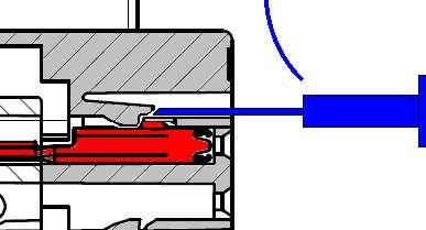
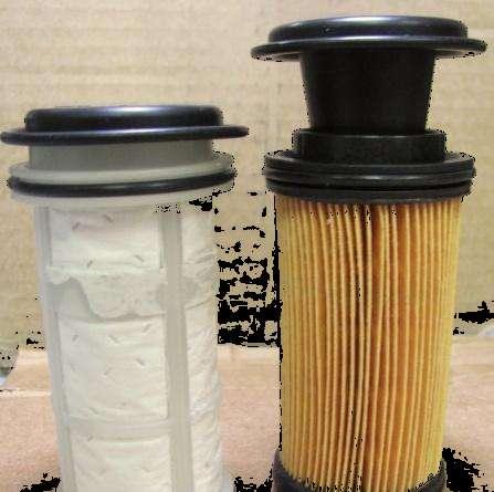
156 Service Kit Service Kit for High Capacity Filter will include Filter element Compensation device/equalizing element Tool for filter removal

157 Current vs New Components Pictures 157

158 158 Non-Interchangeable Components Proper Fit Improper Fit
159 Aftertreatment Hardware Aftertreatment OEM Supplied Parts DEF Line Heaters DEF Lines DEF Line Relays DEF Tank DEF Tank Temperature/Level Sensor/Urea Quality DEF Tank Heater DEF Tank Heater Control Valve controls coolant flow to heat DEF Tank Coolant Lines to tank and Aftertreatment DEF Dosing Valve 159
160 160 Diesel Exhaust Fluid (DEF)
161 Service Bulletin Diesel Exhaust Fluid Specifications for Cummins Selective Catalytic Reduction Systems This service bulletin provides information for Diesel Exhaust Fluid (DEF), a fluid that may have a slight ammonia smell, used with Cummins Selective Catalytic Reduction (SCR) systems. The purpose of this bulletin is to help the user understand correct specifications, usage, and handling of diesel exhaust fluid, which is: Nontoxic and nonpolluting Nonflammable Stable and colorless Composed of urea and water. Urea is naturally occurring and is biodegradable. NOTE: Diesel exhaust fluid is the generic nomenclature, but it is also commonly referred to as AdBlue and Aqueous Urea Solution (AUS)

162 162

163 CAUTION Never attempt to create diesel exhaust fluid by mixing agricultural grade urea with water. Agricultural grade urea does not meet the necessary specifications required and the aftertreatment system may be damaged. Diesel Exhaust Fluid Specifications The urea content of the solution must be 32.5 percent ± 0.7 percent by weight and must meet the International Standard ISO for diesel engines. There is no acceptable substitute. NOTE: Some locations may reference the DIN standard. Diesel exhaust fluid specification limits of this standard are identical to ISO NOTE: Cummins Inc. is not responsible for failures or damage resulting from what Cummins Inc. determines to be abuse or neglect, including but not limited to: operation without correctly specified diesel exhaust fluid, lack of maintenance of the aftertreatment system, improper storage or shutdown practices, unauthorized modifications of the engine and aftertreatment system. Cummins Inc. is also not responsible for failures caused by incorrect diesel exhaust fluid or by water, dirt, or other contaminants in the diesel exhaust fluid. For engines using SCR operating in the United States and Canada, it is also strongly recommended that the diesel exhaust fluid (DEF) used be certified by the American Petroleum Institute (API). This would be indicated by a symbol on the container/dispensing system, as shown. 163
164 CAUTION Never add water or any other fluid besides what is specified to the diesel exhaust fluid (DEF) tank. The aftertreatment system may be damaged. Adding water to the diesel exhaust fluid tank: will change the diesel exhaust fluid concentration levels, which may affect SCR efficiency. may add contaminates and/or affect the chemical properties of the diesel exhaust fluid, which may damage the aftertreatment system. will alter the freeze point and characteristics of the diesel exhaust fluid solution, potentially leading to damaged diesel exhaust fluid dosing system components during cold weather operation. Handling, Storage, and Shelf Life of Diesel Exhaust Fluid Handling: Diesel exhaust fluid is not harmful to handle, but can be reactive and/or corrosive to certain materials over time: Carbon steels, zinc coated carbon steels, and mild iron Nonferrous metals and alloys: copper, copper alloys, zinc, and lead Solders containing lead, silver, zinc, or copper Aluminum and aluminum alloys Magnesium and magnesium alloys Plastics or metals coated with nickel. If diesel exhaust fluid comes in contact with any of the materials referenced, clean immediately. Reference the Disposal and Cleaning of Diesel Exhaust Fluid section of this service bulletin for additional information. 164
165 Shelf Life: The following conditions are ideal for maintaining diesel exhaust fluid quality and shelf life during prolonged transportation and storage: 165 Storage temperature between -5 C to 25 C [23 F to 77 F] Store in sealed containers to reduce the possibility of contamination Avoid direct sunlight. In these conditions, diesel exhaust fluid has a minimum expected shelf life of 18 months. However, each 5 C [9 F] increment above recommended temperatures reduces shelf life by 6 months (for example 30 C [86 F] = 12 month shelf life, 35 C [95 F] = 6 month shelf life, etc.). Storage: Long term storage in a vehicle (in excess of 6 months) is not recommended. If long term storage is necessary, periodic testing of the diesel exhaust fluid is recommended to be performed to make sure the concentration does not fall out of specification. Reference the Testing section of this service bulletin. For detailed information on handling, transportation, and storage, reference ISO Diesel Exhaust Fluid Cleanliness Practices Materials that come into contact with diesel exhaust fluid must be free from any contamination, oil, fuel, dust, detergents, and any other chemicals.
166 NOTE: Spilled diesel exhaust fluid, if left to dry or wiped away with a cloth only, will leave a white residue. Failure to clean the spilled diesel exhaust fluid from a surface may result in an incorrectly diagnosed leak of the diesel exhaust fluid dosing system. Before the use of containers, funnels, etc. that will be used to dispense, handle, or store diesel exhaust fluid, make sure to wash them thoroughly to remove any contaminants and then rinse with distilled water. NOTE: Do not use tap water to rinse components that will be used to deliver diesel exhaust fluid. Tap water will contaminate the diesel exhaust fluid. If distilled water is not available, rinse with tap water and then rinse with diesel exhaust fluid. Disposal and Cleaning of Diesel Exhaust Fluid If spillage occurs, the diesel exhaust fluid should be either transferred into a suitable container, or covered using an absorbent material and then disposed of according to local environmental regulations. The container must be labeled correctly. Do not empty into the drainage system. Do not empty/release into surface water. Very small amounts of diesel exhaust fluid can be rinsed away with a large volume of water. 166
167 First Aid In case of contact with eyes, immediately flush eyes with large amounts of water for a minimum of 15 minutes. Do not swallow internally. In the event that diesel exhaust fluid is ingested, contact a physician immediately. Alternate Names/References for Diesel Exhaust Fluid The following are other names used for diesel exhaust fluid (DEF): Urea AUS 32 (Aqueous Urea Solution 32) AdBlue NOx Reduction Agent Catalyst Solution Stableguard 32. Regardless of what the diesel exhaust fluid is called, it must meet the requirements as outlined in the specifications section of this service bulletin. 167

168 Testing To test the concentration of the diesel exhaust fluid, use the Cummins diesel exhaust fluid refractometer, Part Number Follow the instructions provided with this service tool. For detailed instructions on testing diesel exhaust fluid, reference ISO
169 Freezing Diesel exhaust fluid freezes at approximately -11 C [12 F]. The diesel exhaust fluid system on the vehicle is designed to accommodate this and does not require any intervention by the vehicle operator. For further information, reference the diesel exhaust fluid manufacturer's Material Safety Data Sheet. CAUTION Do not add any chemicals/additives to the diesel exhaust fluid in an effort to prevent freezing. If chemicals/additives are added to the diesel exhaust fluid, the aftertreatment system may be damaged. 169
170 DEF Freeze Point Once the DEF has melted, it can be used without problem. The first melted drop has the same consistency as defined in the Diesel Exhaust Fluid specification. The SCR system is designed to provide heating for the DEF tank and supply lines which will reduce the melting time for frozen DEF. If DEF freezes, start up and normal operation of the vehicle is not inhibited so the operator is not impacted. 170
171 DEF Properties Non-toxic and non-flammable. Safe to handle and store. Poses no serious risk to humans, animals, equipment or the environment if properly handled. The product is slightly alkaline with a ph of approximately
172 How Much will DEF Cost? Automotive grade DEF is only slightly more expensive to produce compared to Agricultural grade DEF. - Requires a higher purity urea base stock and deionized water Higher prices of DEF are associated with smaller containers and low volume suppliers. DEF prices loosely follow natural gas commodity prices 172

173 How Much DEF Will I Use? Approximately 2% DEF consumption 173

174 Private Datalink On Aftertreatment Overview


 NOx heating will")
175 Aftertreatment NOx Sensor 2013 model year engines will be using updated 24 and 12 volt NOx sensors. Accuracy improvement to ± 10 ppm/%, Probe cover to improve water splash resistance Faster response time Extend the temperature range 4 pin connector change 24 volts and 12 volts sensors with specific part # s Inlet and Outlet sensors use different connector key Different internal software for Inlet and Outlet sensors (Preprogrammed) NOx heating will being when the intake NOx sensor reaches 150 C and the outlet NOx sensor reaches 200 C 175


176 Datalinked Temperature Sensors (DPF & SCR) Aftertreatment Diesel Particulate Temperature Sensors Interface Module Aftertreatment SCR Temperature Sensor Interface Module Data Erratic Intermittent or Incorrect - Communication Issues 3144 Aftertreatment 1 SCR Intake Temperature Sensor 3148 Aftertreatment 1 SCR Outlet Temperature Sensor 3228 Aftertreatment 1 Intake NOx Sensor 3315 Aftertreatment 1 Diesel Oxidation Catalyst Intake Temperature 3318 Aftertreatment 1 Diesel Particulate Filter Intake Temperature 3322 Aftertreatment 1 Diesel Particulate Filter Outlet Temperature 3681 Aftertreatment 1 Outlet NOx Sensor Power Supply 3682 Aftertreatment 1 Intake NOx Sensor Power Supply Aftertreatment Diesel Exhaust Fluid Quality 3934 Aftertreatment Outlet NH3 Gas Sensor Power Supply

")

177 Aftertreatment Intermediate NH3 Sensor Smart component (datalink) Designed to measure amount of the NH3 Gas (ammonia) and determine if DEF properly utilized (overspray and underspray) 177
178 2013 On-Board Diagnostics (OBD) Version /20/2014
179 2013 OBD Requirements Mandated for all automotive Cummins engines MIL lamps strategy INSITE fault code reading and clearing strategy Inducement charts (DEF) 179
180 On-Board Diagnostics (OBD) Terminology Diagnostic Trouble Code (DTC) A code reported and stored by the engine ECM which indicates a particular malfunction has been detected. Same as Cummins Fault Code. Malfunction Indicator Lamp (MIL) A dash lamp used to notify the operator when a malfunction has been detected that could impact emissions. 180
181 On-Board Diagnostics (OBD) Terminology Trip Definition condition(s) the engine must operate in order to run the diagnostics and ends with either key-off or 4 hours of engine run time Can be key-on, idle, stationary regen, etc OBD faults will require multiple trips to light the MIL After 1 trip has failed the fault code will be shown as active in INSITE After MIL is lit the fault will show inactive after 1 trip passes, MIL will go out once all trips have passed Example 3 trips to light MIL, 3 trips to clear MIL
182 What s different in an OBD system? Malfunction Indicator Lamp (MIL) Latches ON when an OBD fault code is logged It takes 3 operation cycles (without the fault reoccurring) to clear the lamp Extended diagnosing time is necessary for the various rationality and system monitors Diagnostic approaches must be approved by the regulatory agency (including calibrations) The OBD system detects deteriorated systems and components (not just total failures) 2 trip diagnostics exist; i.e. the failure must be detected in 2 consecutive trips before the MIL will be illuminated Cummins must demonstrate the OBD system s capabilities to detect failures Changes to the system once in production must be approved by the regulatory agency 182
183 2010 / 2013 HD-OBD Driver Interface 3 Lamp Strategy CHECK ENGINE CHECK ENGINE Check Engine Lamp - (Amber Warning Lamp) This is the standard lamp that we have used in all previous Cummins applications. Used for Non-OBD faults. Stop Engine Lamp Used to indicate Engine Protection Fault Codes. Malfunction Indicator Lamp (MIL) This lamp is used to indicate an Emissions Related Failure has occurred (OBD Faults). 183
184 Recommended Service Direction Follow Conditions for Clearing the Fault Code to perform one trip for verification purposes. Once fault code is Inactive, use INSITE Reset All Faults option to clear the fault code and extinguish the MIL. 184

185 185

186 Reset All Faults option to clear MIL 186
187 Watchouts Do not use Reset Inactive Faults if MIL is illuminated and there are no active faults. MIL will stay latched ON until 3 consecutive successful trips are completed. No fault code available in INSITE to select the Reset All Faults option. 187

188 MIL still illuminated Reset All Faults option is not available 188
Presented by. Navistar Education 2015
 Presented by Navistar Education 2015 1.2 Overview This course is intended to provide parts specialists with a description of Diesel Exhaust Fluid, or DEF, part number configuration, ordering and distribution
2013 Aftertreatment System with SCR Overview for Technicians Study Guide
 TMT121340 Class Course Code: 8359 2013 Aftertreatment System with SCR Overview for Technicians Study Guide 2013 Aftertreatment System with SCR Study Guide 2013 Navistar, Inc. All rights reserved. All marks
CUMMINS ENGINE ISX15 ISX CM2250 Service Workshop Manual
 Instant Manual Download CUMMINS ENGINE ISX15 ISX CM2250 Service Workshop Manual Download Here CUMMINS ENGINE ISX15 Service Workshop Repair Shop Manual PLEASE NOTE: YOU NEED TO BE CONNECTED TO THE INTERNET
DASH RETRIEVED FAULT CODES C ONVENTIONAL FS65 SAF T LINER C2, C2E H YBRID SAF T LINER HDX, HD, ER SAF T LINER EF, EFX A LL Y EARS
 DASH RETRIEVED FAULT CODES C ONVENTIONAL FS65 SAF T LINER C2, C2E H YBRID SAF T LINER HD, HD, ER SAF T LINER EF, EF A LL Y EARS PAGE INTENTIONALLY LEFT BLANK TABLE OF CONTENTS EARLY PRODUCTS: J1587/J1708
Exhaust After-Treatment System. This information covers design and function of the Exhaust After-Treatment System (EATS) on the Volvo D16F engine.
 on the Volvo D16F engine.") Volvo Trucks North America Greensboro, NC USA DService Bulletin Trucks Date Group No. Page 1.2007 258 44 1(6) Exhaust After-Treatment System Design and Function D16F Exhaust After-Treatment System W2005772
Volvo Trucks North America Greensboro, NC USA DService Bulletin Trucks Date Group No. Page 1.2007 258 44 1(6) Exhaust After-Treatment System Design and Function D16F Exhaust After-Treatment System W2005772
2010 MidRange Engines
 2010 MidRange Engines Global On-Highway Standards 5.0 4.5 NOx g/hp-hr 4.0 3.5 3.0 2.5 2.0 EURO IV EURO V US98 US04 1.5 1.0 0.5 US07 EURO VI 0.0 US10 0.0 0.01 0.02 0.03 0.04 0.04 0.04 0.06 0.07 0.08 0.09
Engine Emission Control 6.7L Diesel
 Page 1 of 6 SECTION 303-08: Engine Emission Control 2011 F-250, 350, 450, 550 Super Duty Workshop Manual DESCRIPTION AND OPERATION Procedure revision date: 03/12/2010 Engine Emission Control 6.7L Diesel
CANDO Diagnostic List Cummins_v8.27
 CANDO Diagnostic List Cummins_v8.27 Remark: 1. : means that the system has this function 2. - : means that the system does not have this function 3.compared with the last version, the new added function
TMT121336EN 8355 R EPA, 2013 N13 Engine Aftertreatment System Overview for Technicians Study Guide
 TMT121336EN 8355 R1 2010 EPA, 2013 N13 Engine Aftertreatment System Overview for Technicians Study Guide 2010 EPA, 2013 N13 Engine Aftertreatment System STUDY GUIDE 2014 Navistar, Inc. 2701 Navistar Drive,
Cummins engine Signature ISX QSX15 Service Workshop Shop Repair Manual - PDF Service Manual
 Cummins engine Signature ISX QSX15 Service Workshop Shop Repair Manual - PDF Service Manual DOWNLOAD HERE "Cummins engine Signature ISX QSX15 Service Workshop Shop Repair Manual - PDF Service Manual Signature
Engine Performance Troubleshooting Tree - Signature and ISX CM870
 File: 70-t02-1001 Page 1 of 64 Engine Performance Troubleshooting Tree - Signature and ISX CM870 This troubleshooting procedure should be followed for the following symptoms: Engine Acceleration or Response
Section 10 Chapter 7
 Section 10 Chapter 7 24 Valve, 8.3 Liter Engine Troubleshooting Symptoms Identification Note: All coding used in the 8.3 Liter and 9 Liter engine manuals are Cummins engine codes. These engine codes have
Table of Contents. Foreword...1. Service Diagnosis...2. Safety Information...3. Engine Systems...5. Mounting Engine on Engine Stand...
 ENGINE SERVICE MANUAL I Table of Contents Foreword...1 Service Diagnosis...2 Safety Information...3 Engine Systems...5 Mounting Engine on Engine Stand...55 Engine Electrical...65 Variable Geometry Turbocharger
INTRODUCING CE SERIES WITH CUMMINS ISB6.7
 INTRODUCING CE SERIES WITH CUMMINS ISB6.7 OVERVIEW 1. Introducing the Cummins ISB6.7 2. Cummins ISB6.7 Features, Technology and Enhancements 3. The CE Engine Portfolio INTRODUCING THE CUMMINS ISB6.7 What
Additions, Revisions, or Updates
 4 68-12 1 4 68-12 SUBJECT DATE SPN 5018/FMI 18 - GHG14 September 2012 Additions, Revisions, or Updates Publication Number / Title Platform Section Title Change DDC-SVC-MAN-0084 DD Platform SPN 5018/FMI
The Path To EPA Tier 4i - Preparing for. the 2011 transition
 The Path To EPA Tier 4i - Preparing for Presented by: Todd Howe Global Product Marketing Manager Doosan Infracore Portable Power Office: 704-883-3611 todd.howe@doosan.com the 2011 transition About the
TABLE OF CONTENTS. Foreword...1. Service Diagnosis...2. Safety Information...3. Engine Systems...5. Mounting Engine on Engine Stand...
 ENGINE SERVICE MANUAL I TABLE OF CONTENTS Foreword...1 Service Diagnosis...2 Safety Information...3 Engine Systems...5 Mounting Engine on Engine Stand...53 Engine Electrical...63 Cold Start Assist...111
Study Guide MaxxForce TM 5 Engine Update TMT
 A N AV I S TA R C O M PA N Y MaxxForce TM 5 Engine Update Study Guide TMT-120710 Study Guide MaxxForce TM 5 Engine Update TMT-120710 2007 International Truck and Engine Corporation 4201 Winfield Road,
Service Bulletin No. 2969C
 MODEL TYPE SECTION/GROUP DATE E / J Series Coaches Service Information 8--Engine April 13, 2009 SUBJECT CUMMINS ISM DIESEL EPA ENGINES CONDITIONS Service Information Only THIS BULLETIN SUPERCEDES FIELD
 TO: GRADALL Excavator Service Managers AFFECTED MODEL: Series IV Highway Speed Excavators SUBJECT: T4i Emissions System Resource Website RELEASE DATE: January 18, 2013 BULLETIN NUMBER: 41200113 The GRADALL
Section 10 Chapter 17
 Section 10 Chapter 17 24 Valve, 8.3 Liter Engine Air Intake System Note: All coding used in the 8.3 Liter and 9 Liter engine manuals are Cummins engine codes. These engine codes have no meaning to New
Additions, Revisions, or Updates
 1 11 19-13 SUBJECT DATE SPN 3216/FMI 2, 18 GHG14 (MCM2.1) November 2013 Additions, Revisions, or Updates Publication Number / Title Platform Section Title Change SPN 3216/FMI 2 DDC-SVC-MAN-0084 GHG14 DD
Systems Operation, Testing and Adjusting
 Systems Operation, Testing and Adjusting 3176C and 3196 Engines for Caterpillar Built Machines S/N: 4SS00001-UP (Excavators 345B) S/N: 7ZR01004 (ENGINE) Use the bookmarks for navigation inside of the manual
OCTOBER 2015 DLTN9501A-ILT
 OCTOBER 2015 DLTN9501A-ILT This book is designed for instructional use only for authorized Nissan North America, Inc. and Nissan dealer personnel. For additional information contact: Nissan North America,
DTC P20EE, P249D, P249E, or P2BAD
 Page 1 of 7 Document ID: 2614257 DTC P20EE, P249D, P249E, or P2BAD Diagnostic Instructions Perform the Diagnostic System Check - Vehicle prior to using this diagnostic procedure. Review Strategy Based
TABLE OF CONTENTS. Foreword...1. Service Diagnosis...2. Safety Information...3. Engine Systems...5. Mounting Engine on Engine Stand...
 ENGINE SERVICE MANUAL I TABLE OF CONTENTS Foreword...1 Service Diagnosis...2 Safety Information...3 Engine Systems...5 Mounting Engine on Engine Stand...59 Engine Electrical...71 Down Stream Injection
General Information. Note : The aftertreatment DOC is integrated into the inlet of the exhaust aftertreatment system. WARNING
 General Information The material captured in a diesel particulate filter may contain elevated concentrations of media, primarily zinc and molybdenum, and possibly polynuclear aromatic hydrocarbons that
Additions, Revisions, or Updates
 1 10 26-13 SUBJECT DATE SPN 3216/FMI 16 and 18 October 2013 Additions, Revisions, or Updates Publication Number / Title Platform Section Title Change DDC-SVC-MAN-0084 GHG14 DD Platform SPN 3216/FMI 16
Section 10 Chapter 6
 Section 10 Chapter 6 24 Valve, 8.3 Liter Engine Identification Note: All coding used in the 8.3 Liter and 9 Liter engine manuals are Cummins engine codes. These engine codes have no meaning to New Holland
Contents Safety. Emergency. Controls. Driving. Maintenance. Information. Index
 Contents Safety Emergency Controls Driving Maintenance Information Index 1 2 4 5 6 7 Contents 2010 Paccar Inc - All Rights Reserved This manual illustrates and describes the operation of features or equipment
Contents Safety. Emergency. Controls. Driving. Maintenance. Information. Index
 Contents Safety Emergency Controls Driving Maintenance Information Index 1 2 4 5 6 7 Contents 2012 Paccar Inc - All Rights Reserved This manual illustrates and describes the operation of features or equipment
Technician Turbocharger Guide for the L Power Stroke Engine
 Technician Turbocharger Guide for the 2003.25 6.0L Power Stroke Engine Vanes VGT Actuator Piston Turbine Wheel Shaft Seal Compressor Wheel VGT Control Valve TURBOCHARGER DESCRIPTION AND BASIC OPERATION
Table of Contents. Foreword Service Diagnosis Safety Information Engine Systems Mounting Engine on Engine Stand...
 ENGINE SERVICE MANUAL I Table of Contents Foreword... 1 Service Diagnosis... 2 Safety Information... 3 Engine Systems... 5 Mounting Engine on Engine Stand...59 EVRT Electronically Controlled Turbocharger...67
SPN 4364/FMI 17 - GHG17 SPN /FMI 16 - GHG17 SPN /FMI 14 - GHG17 SPN 3216/FMI 16 - GHG17 SPN 3216/FMI 18 - GHG17 SPN 3217/FMI 2 - GHG17
 11 29-16 1 11 29-16 SUBJECT SPN 4364 (ACM) (GHG17) SPN 520371 (ACM) (GHG17) SPN 520372 (ACM) (GHG17) SPN 3216 (ACM) (GHG17) SPN 3217 (ACM) (GHG17) SPN 3226 (ACM) (GHG17) SPN 3227 (ACM) (GHG17) Diagnostic
Automotive Fuel and Emissions Control Systems 4/E
 Automotive Fuel and Emissions Control Systems 4/E Opening Your Class KEY ELEMENT Introduce Content Motivate Learners State the learning objectives for the chapter or course you are about to cover and explain
Trucks. Group 28 MID 128 Fault Code Guide 2007 Emissions VN, VHD VERSION2, VT PV
 Service Manual Trucks MID 128 Fault Code Guide 2007 Emissions VN, VHD VERSION2, VT PV776-20184635 Foreword The descriptions and service procedures contained in this manual are based on designs and methods
Additions, Revisions, or Updates
 1 SUBJECT SPN 3216 (ACM) (GHG17) SPN 3217 (ACM) (GHG17) DATE March 2017 Additions, Revisions, or Updates Publication Number / Title Platform Section Title Change DDC-SVC-MAN-0193 GHG17 Medium Duty SPN
FOR HELP WITH USING witech FOR ECU FLASH REPROGRAMMING, CLICK ON THE APPLICATION S HELP TAB.
 NUMBER: 18-091-16 GROUP: Vehicle Performance DATE: July 26, 2016 This bulletin is supplied as technical information only and is not an authorization for repair. No part of this publication may be reproduced,
CUMMINS ENGINE DIAGNOSTIC CODES
 ENGINE DIAGNOSTICS GROUP 105 CUMMINS ENGINE DIAGNOSTIC CODES 1 INTRODUCTION... 1 2 TROUBLESHOOTING CODES... 1 1 INTRODUCTION. This group provides information on the engine fault codes that could potentially
Fuel Pump ( ) Table of Contents. Summary. View Related Topic. Summary. General Information Test. Preparatory Steps. Remove.
 Table of Contents. Summary. View Related Topic. Summary. General Information Test. Preparatory Steps. Remove.") View Related Topic Fuel Pump (005-016) Table of Contents Summary General Information Test Without Electric Lift Pump With Electric Lift Pump Preparatory Steps Marine Applications Remove Rear Gear Train
View Related Topic Fuel Pump (005-016) Table of Contents Summary General Information Test Without Electric Lift Pump With Electric Lift Pump Preparatory Steps Marine Applications Remove Rear Gear Train
Tier 4 Bobcat Engine. Andrew Johnson Product Service Manager, Bobcat Company Rocky Mountain Asphalt Conference and Equipment Show Feb.
 Tier 4 Bobcat Engine Andrew Johnson Product Service Manager, Bobcat Company Rocky Mountain Asphalt Conference and Equipment Show Feb. 21 st 2018 Overview Tier 4 Diesel Engine Technologies Bobcat s Tier
DEF Q&A. A. SCR is a technology that uses a urea based diesel exhaust fluid (DEF) and a
 and a") Selective Catalytic Reduction (SCR) Q. What is Selective Catalytic Reduction (SCR)? A. SCR is a technology that uses a urea based diesel exhaust fluid (DEF) and a catalytic converter to significantly reduce
Selective Catalytic Reduction (SCR) Q. What is Selective Catalytic Reduction (SCR)? A. SCR is a technology that uses a urea based diesel exhaust fluid (DEF) and a catalytic converter to significantly reduce
NUMBER: S.M. REF.: Listed in Table ENGINE: EPA07 Series 60 DATE: October 2012 SUBJECT: REFERENCES TO THE TURBOCHARGER PURGE ROUTINE
 NUMBER: 10 01 12 S.M. REF.: Listed in Table ENGINE: EPA07 Series 60 DATE: October 2012 SUBJECT: REFERENCES TO THE TURBOCHARGER PURGE ROUTINE ADDITIONS, REVISIONS, OR UPDATES Publication Number Platform
Oregon Fuel Injection
 2001 2006 Dodge Mercedes - Freightliner Sprinter Diagnostics In order to do proper diagnostics you will need a scan tool and some special tools available from Mopar Special Tools http://mopar.snapon.com.
2010 MaxxForce 11 and 13L Diagnostics
 2010 MaxxForce 11 and 13L Diagnostics Study Guide TMT-121130 Study Guide 2010 MaxxForce 11 and 13L Diagnostics TMT-121130 2011 Navistar, Inc. 4201 Winfield Road, Warrenville, IL 60555. All rights reserved.
TABLE OF CONTENTS. Foreword...1. Service Diagnosis...2. Safety Information...3. SCR Component Locator Guide...7. Engine Systems...
 DIAGNOSTIC MANUAL I TABLE OF CONTENTS Foreword...1 Service Diagnosis...2 Safety Information...3 SCR Component Locator Guide...7 Engine Systems...13 Engine and Vehicle Features...75 Diagnostic Software
Air Management System Components
 AIR M anagement Sys tem Air Management System Components Air Management System Features Series Sequential The series sequential turbocharger is a low pressure/high pressure design working in series with
EVERY ALTERNATIVE. Next Generation Natural Gas Engine 4/23/2013. Why Natural Gas Engines for Buses & Trucks?
 EVERY ALTERNATIVE. Why Natural Gas Engines for Buses & Trucks? Emissions Leadership Meet 2010 EPA Emissions in Next Generation Natural Gas Engine Economic Benefits Continued reliability improvement Improved
FOR HELP WITH USING witech FOR ECU FLASH REPROGRAMMING, CLICK ON THE APPLICATION S HELP TAB.
 NUMBER: 18-043-17 GROUP: Vehicle Performance DATE: May 04, 2017 This bulletin is supplied as technical information only and is not an authorization for repair. No part of this publication may be reproduced,
QuickServe Online ( ) ISB6.7 CM2350 B101 Service Manual
 ISB6.7 CM2350 B101 Service Manual") Page 1 of 31 (/qs3/pubsys2/xml/en/manual/2883567/2883567-titlepage.html) Select Service Tools Recommended Cummins Service Tools 0.043 inch orificed diagnostic fuel line, Part Number 3164621 Diagnostic
Page 1 of 31 (/qs3/pubsys2/xml/en/manual/2883567/2883567-titlepage.html) Select Service Tools Recommended Cummins Service Tools 0.043 inch orificed diagnostic fuel line, Part Number 3164621 Diagnostic
TC Series Cooling Systems
 TC Series Cooling Systems Table of Contents Table of Contents...1 List of Figures...1 Safety...2 Introduction...2 General Specifications...2 Types of Coolant...2 Routine Maintenance...2 Surge Tank Coolant
Exhaust System - 2.2L Diesel
 Page 1 of 9 Published: Mar 8, 2007 Exhaust System - 2.2L Diesel COMPONENT LOCATION - WITH DIESEL PARTICULATE FILTER Item Part Number Description 1 Exhaust manifold (ref only) 2 Pressure differential sensor
Service Bulletin Published by Sudden Service, Inc.
 Service Bulletin Published by Sudden Service, Inc. Volume 18 / Number 2 / February 1, 2018 Louisville, Mississippi Preventative Maintenance (PM) Requirements for Diesel Engines Equipped With EPA Tier 4
INTERNATIONAL Diesel Engine Emissions Requirements & Technology
 INTERNATIONAL 2010 Diesel Engine Emissions Requirements & Technology Independent Armored Car Operators Association, Inc. 2008 Annual Convention Monday, June 23, 2008 2007 EPA Emissions Standards 1994 500
SPN 4364 (ACM)(EPA10); SPN 4364 (ACM)(GHG14) January Publication Number / Title Platform Section Title Change SPN 4364/FMI 18 - EPA10
(EPA10); SPN 4364 (ACM)(GHG14) January Publication Number / Title Platform Section Title Change SPN 4364/FMI 18 - EPA10") 01 01-18 1 01 01-18 SUBJECT DATE SPN 4364 (ACM)(EPA10); SPN 4364 (ACM)(GHG14) January 2018 Additions, Revisions, or Updates Publication Number / Title Platform Section Title Change DDC-SVC-MAN-0084 DD
01 01-18 1 01 01-18 SUBJECT DATE SPN 4364 (ACM)(EPA10); SPN 4364 (ACM)(GHG14) January 2018 Additions, Revisions, or Updates Publication Number / Title Platform Section Title Change DDC-SVC-MAN-0084 DD
INTAKE AND EXHAUST GROUP CONTENTS CHARGE AIR COOLER <2.0L ENGINE> GENERAL DESCRIPTION SERVICE SPECIFICATIONS...
 15-1 GROUP 15 INTAKE AND EXHAUST CONTENTS GENERAL DESCRIPTION 15-2 SERVICE SPECIFICATIONS 15-2 DIAGNOSIS 15-2 INTRODUCTION 15-2 TROUBLESHOOTING STRATEGY 15-2 SYMPTOM CHART 15-2 SYMPTOM PROCEDURES 15-3
Chapter 20 OBD-II Diesel Monitors
 Light Vehicle Diesel Engines First Edition Chapter 20 OBD-II Diesel Monitors LEARNING OBJECTIVES (1 of 2) 20.1 Prepare for the Light Vehicle Diesel Engine (A9) ASE certification fuel system diagnosis and
ISC, QSC8.3, and ISL (FIS )
") Fault Information System... 1 FIS Usage Recommendations... 2 FIS Usage Recommendations... 2 Diagnostic Methods... 9 Troubleshooting Fault Codes... 9 Information Fault Codes... 3 (fc211) Fault Code 211...
Fault Information System... 1 FIS Usage Recommendations... 2 FIS Usage Recommendations... 2 Diagnostic Methods... 9 Troubleshooting Fault Codes... 9 Information Fault Codes... 3 (fc211) Fault Code 211...
Fuel Metering System Component Description
 1999 Chevrolet/Geo Tahoe - 4WD Fuel Metering System Component Description Purpose The function of the fuel metering system is to deliver the correct amount of fuel to the engine under all operating conditions.
ENGINE AND EMISSION CONTROL
 17-1 ENGINE AND EMISSION CONTROL CONTENTS ENGINE CONTROL SYSTEM........ 3 SERVICE SPECIFICATION............... 3 ON-VEHICLE SERVICE.................. 3 Accelerator Cable Check and Adjustment... 3 ACCELERATOR
m b e E M I S S I O N S E N G I N E
 m b e 4 0 0 0 2 0 0 7 E M I S S I O N S E N G I N E We re DRIVING TECHNOLOGY. Detroit Diesel and Mercedes-Benz have over 150 combined years of experience designing, testing and manufacturing diesel engines.
SECTION D Engine 6.0L Diesel
 303-01D-i Engine 6.0L Diesel 303-01D-i SECTION 303-01D Engine 6.0L Diesel CONTENTS PAGE DESCRIPTION AND OPERATION Engine... 303-01D-2 303-01D-2 Engine 6.0L Diesel 303-01D-2 DESCRIPTION AND OPERATION Engine
C18 ACERT Fire Pump Tier bkw/ rpm
 CATERPILLAR ENGINE SPECIFICATIONS I-6, 4-Stroke-Cycle Diesel Bore...145.0 mm (5.71 in) Stroke...183.0 mm (7.2 in) Displacement... 18.1 L (1,104.53 in3) Aspiration...Turbocharged Aftercooled Compression
 Page 1 of 9 303-01C Engine 6.0L Diesel 2004 F-Super Duty 250-550/Excursion DESCRIPTION AND OPERATION Procedure revision date: 08/06/2003 Engine Printable View Engine Description The 6.0L diesel engine
Additions, Revisions, or Updates
 1 12 02-12 SUBJECT DATE Test E - Three-Filter Fuel System December 2012 Additions, Revisions, or Updates Publication Number / Title Platform Section Title Change DDC-SVC-MAN-0084 DD Platform Test E - Three-Filter
THE witech SOFTWARE IS REQUIRED TO BE AT THE LATEST RELEASE BEFORE PERFORMING THIS PROCEDURE.
 NUMBER: 18-057-15 GROUP: Vehicle Performance DATE: July 25, 2015 This bulletin is supplied as technical information only and is not an authorization for repair. No part of this publication may be reproduced,
EveryTM. Coverage. North American Truck Coverages For 2013 ISL9 And ISB6.7 Engines.
 EveryTM Coverage. North American Truck Coverages For 2013 ISL9 And ISB6.7 Engines. EveryTM Confidence. You can have confidence knowing that your Cummins 2013 engine is backed by the total coverage of Cummins
Powertrain DTC Summaries EOBD
 Powertrain DTC Summaries Quick Reference Diagnostic Guide Jaguar X-TYPE 2.0 L 2002.25 Model Year Refer to page 2 for important information regarding the use of Powertrain DTC Summaries. Jaguar X-TYPE 2.0
3406E Truck Engine 5EK01821-UP(SEBP ) - Document Structure. Media Number -RENR Publication Date -01/02/2008 Date Updated -07/02/2008
 - Document Structure. Media Number -RENR Publication Date -01/02/2008 Date Updated -07/02/2008") Page 1 of 11 Shutdown SIS Previous Screen Product: TRUCK ENGINE Model: 3406E TRUCK ENGINE 5EK Configuration: 3406E Truck Engine 5EK01821-UP Systems Operation 3406E Truck Engine Media Number -RENR1273-07
Page 1 of 11 Shutdown SIS Previous Screen Product: TRUCK ENGINE Model: 3406E TRUCK ENGINE 5EK Configuration: 3406E Truck Engine 5EK01821-UP Systems Operation 3406E Truck Engine Media Number -RENR1273-07
using Diesel exhaust fluid with the duramax 6.6L turbo-diesel
 using Diesel exhaust fluid with the duramax 6.6L turbo-diesel the most powerful duramax diesel ever now runs cleaner too! using diesel exhaust fluid new system reduces tailpipe Nox emissions The enhanced,
Engine Replacement Procedures September Removal of the Complete Powertrain Assembly. Replacement Long Block Engine Preparation
 9 05-15 1 9 05-15 SUBJECT DATE Engine Replacement Procedures September 2015 Additions, Revisions, or Updates Publication Number / Title Platform Section Title Change Removal of the Complete Powertrain
2200 Series 2206F/J-E13TA Industrial Engine EU Stage V/U.S. EPA Tier 4 Final/Japan 2014/Korea Tier 4 Final kw / hp
 The ability to power your machine line-up with one engine supplier is truly achieveable with Perkins. We have introduced a platform of 9-18 litre industrial engines that completes our market-leading industrial
Perfectly Adapted. ISL Euro 6 Diesel Engine PS
 ISL Euro 6 Diesel Engine 280-380PS The SCR aftertreatment system used at Euro 5 has been updated by Cummins Emission Solutions. For Euro 6 the compact design incorporates a diesel particulate filter to
Driver Tips For Fire And Emergency Vehicles. For EPA 2013 Cummins On-Highway Heavy-Duty And MidRange Engines With Aftertreatment.
 Driver Tips For Fire And Emergency Vehicles. For EPA 2013 Cummins On-Highway Heavy-Duty And MidRange Engines With Aftertreatment. This guide covers engine, aftertreatment and emissions-related indicator
Information Type: Date: 2014/5/14 Profile: WLO, L150G [GB] Service Information
![Information Type: Date: 2014/5/14 Profile: WLO, L150G [GB] Service Information](/thumbs/80/80567703.jpg "Information Type: Date: 2014/5/14 Profile: WLO, L150G [GB] Service Information") Service Information Document Title: Engine, description Function Group: 200 Information Type: Service Information Date: 2014/5/14 Profile: WLO, L150G [GB] Go back to Index Page Engine, description Engines
Service Information Document Title: Engine, description Function Group: 200 Information Type: Service Information Date: 2014/5/14 Profile: WLO, L150G [GB] Go back to Index Page Engine, description Engines
C18 ACERT Fire Pump Tier bkw/ rpm
 CATERPILLAR ENGINE SPECIFICATIONS I-6, 4-Stroke-Cycle Diesel Bore...145.0 mm (5.71 in) Stroke...183.0 mm (7.2 in) Displacement... 18.1 L (1,104.53 in3) Aspiration...Turbocharged Aftercooled Compression
C18 ACERT Fire Pump Tier bkw/ rpm
 CATERPILLAR ENGINE SPECIFICATIONS I-6, 4-Stroke-Cycle Diesel Bore...145.0 mm (5.71 in) Stroke...183.0 mm (7.2 in) Displacement... 18.1 L (1,104.53 in3) Aspiration...Turbocharged Aftercooled Compression
P249E-CLOSED LOOP SCR REDUCTANT INJECTION CONTROL AT LIMIT - FLOW TOO HIGH
 2015 - DJ - RAM 2500 PICKUP - 6.7L I6 CUMMINS TURBO DIESEL P249E-CLOSED LOOP SCR REDUCTANT INJECTION CONTROL AT LIMIT - FLOW TOO HIGH For a complete wiring diagram, refer to the Wiring Information. When
1012-Electrical Diagrams
 Term Absolute Pressure 1012-Electrical Diagrams Definition Total or true pressure. Gauge pressure plus atmospheric pressure. Absolute that includes the atmospheric pressure in its reading. This sensor
Inspection of Vehicles Equipped with 2007 or Later EPA-Certified Engines
 Summary Created: Nov. 19, 2008 Revised: May 19, 2010 Revised: April 27, 2017 This Inspection Bulletin explains how to safely inspect motorcoaches, buses, trucks and truck tractors equipped with 2007 or
UENR4504 January Troubleshooting. 854F-E34TA Industrial Engine. JU (Engine) This document has been printed from SPI2.
 This document has been printed from SPI2.") UENR4504 January 2015 Troubleshooting 854F-E34TA Industrial Engine JU (Engine) Important Safety Information Most accidents that involve product operation, maintenance and repair are caused by failure to
UENR4504 January 2015 Troubleshooting 854F-E34TA Industrial Engine JU (Engine) Important Safety Information Most accidents that involve product operation, maintenance and repair are caused by failure to
C18 ACERT Fire Pump Tier bkw/ rpm
 CATERPILLAR ENGINE SPECIFICATIONS I-6, 4-Stroke-Cycle Diesel Bore...145.0 mm (5.71 in) Stroke...183.0 mm (7.2 in) Displacement... 18.1 L (1,104.53 in3) Aspiration...Turbocharged Aftercooled Compression
ENGINE TECHNOLOGY. Bobcat Engine_B _ _EN_reworked.indd 1
 ENGINE TECHNOLOGY Bobcat Engine_B4459500_01-2015_EN_reworked.indd 1 1/30/2015 10:07:51 AM A COMPANY THAT S GROWING WITH SOCIETY Bobcat prides itself on innovations that shape the future. For decades, we
EveryTM. Alternative. ISL G. Natural Gas Engines For Truck And Bus.
 EveryTM Alternative. ISL G. Natural Gas Engines For Truck And Bus. Natural Gas Engines For Truck And Bus. Lower Emissions, Improved Performance, Lower Costs. The ISL G is the newest evolution of alternative
Oregon Fuel Injection
 Cummins PT Fuel Pump Diagnostic No Start, with no smoke 1. This could be caused by the fuel pump not turning or a seized gear pump. Remove the fuel supply hose and the fuel inlet fitting from the gear
2016 Isuzu Truck 23.1
 2016 Isuzu Truck 23.1 N-SERIES UNDERSTANDING DPF REGENERATION; MODES OF REGENERATION QUICK REFERENCE GUIDE 2011-2015MY Isuzu N-Series Equipped with Diesel Particulate Filter (DPF) 2016 Isuzu Truck 23.2
Additions, Revisions, or Updates
 1 9 04-11 SUBJECT DATE SPN 3250 / FMI 16 DOC Outlet Temperature High August 2011 Additions, Revisions, or Updates Publication Number / Title Platform Section Title Change DDC-SVC-MAN-0084 EPA07 DD13/DD15
DIAGNOSTIC REPORT. Vehicle Components. Vehicle Key Data Points
 Page 1 of 5 Vehicle Components Engine Cummins 15.0L ISX3 79270697 03684275 04017048 030711195725 08000084 B0 BAC High/Low Speed Brakes Bendix EC-60 Premium ABS N/A BB40970 High/Low Speed Vehicle Key Data
EMISSION CONTROL (AUX. EMISSION CONTROL DEVICES) H4SO
 H4SO") EMISSION CONTROL (AUX. EMISSION CONTROL DEVICES) H4SO SYSTEM OVERVIEW 1. System Overview There are three emission control systems, which are as follows: Crankcase emission control system Exhaust emission
EMISSION CONTROL (AUX. EMISSION CONTROL DEVICES) H4SO SYSTEM OVERVIEW 1. System Overview There are three emission control systems, which are as follows: Crankcase emission control system Exhaust emission
1200 Series 1206F-E70TTA Industrial Open Power Unit EU Stage IV, EPA Tier 4 Final kw / hp
 The addition of the 1206F IOPU to our 1200 Series ensures our customers have a complete power solution ready and available when they need to change over to the next stage of emissions legislation EU Stage
Engine Systems. Basic Engine Operation. Firing Order. Four Stroke Cycle. Overhead Valves - OHV. Engine Design. AUMT Engine Systems 4/4/11
 Advanced Introduction Brake to Automotive Systems Diagnosis Service and Service Basic Engine Operation Engine Systems Donald Jones Brookhaven College The internal combustion process consists of: admitting
2800 Series 2806F/J-E18TA/TTA Industrial Engine U.S. EPA Tier 4 Final / EU Stage V-capable* kw / hp
 The ability to power your machine line-up with one engine supplier is truly achieveable with Perkins. We have introduced a platform of 9-18 litre industrial engines that completes our market-leading industrial
DIAGNOSTIC REPORT. Vehicle Components. Vehicle Key Data Points
 Page 1 of 5 Vehicle Components Engine Cummins 15.0L ISX2 79312438 03684275 05026491 052311201001 08000091 B0 BAC High/Low Speed Brakes Bendix EC-60 Standard ABS N/A BB40905 High/Low Speed Vehicle Key Data
EMISSION CONTROL (AUX. EMISSION CONTROL DEVICES) H4DOTC
 H4DOTC") EMISSION CONTROL (AUX. EMISSION CONTROL DEVICES) H4DOTC SYSTEM OVERVIEW 1. System Overview There are three emission control systems, which are as follows: Crankcase emission control system Exhaust emission
EMISSION CONTROL (AUX. EMISSION CONTROL DEVICES) H4DOTC SYSTEM OVERVIEW 1. System Overview There are three emission control systems, which are as follows: Crankcase emission control system Exhaust emission
Power Rating Minimum Power 250 bkw 335 BHP Maximum Power 340 bkw 456 BHP
 The Cat C9.3B Diesel Engine is offered in ratings ranging from 250-340 bkw (335-456 bhp) @ 1800-2200 rpm. These ratings meet U.S. EPA Tier 4 Final and EU Stage V emission standards. The C9.3B engines are
NUMBER: S.M. REF.: Refer to 2.5 ENGINE: 60 DATE: January 2007
 NUMBER: 1 60 07 S.M. REF.: Refer to 2.5 ENGINE: 60 DATE: January 2007 SUBJECT: N3 ELECTRONIC INJECTOR PUBLICATION: 6SE483 The Series 60 Service Manual has been revised. Engine models built from December
EMISSION CONTROL EMISSION CONTROLS
 EMISSION CONTROL EMISSION CONTROLS Emissions control systems on Land Rover vehicles work closely with fuel system controls to reduce airborne pollutants. Improper operation of these systems can lead to
Vehicle Components. (High)/J1587 (Low) Intersection Preemption Emitter. Mack Aftertreatment Control Module
/J1587 (Low) Intersection Preemption Emitter. Mack Aftertreatment Control Module") VIN Vehicle Make Model Model Year 1M1AX07Y6DM018285 Mack GU/Granite Series 2013 Vehicle s Serial Number Software Version Network Engine Mack MP8 12358103 22468510 J1939 Vehicle ECU VMAC IV VECU 12260114
VIN Vehicle Make Model Model Year 1M1AX07Y6DM018285 Mack GU/Granite Series 2013 Vehicle s Serial Number Software Version Network Engine Mack MP8 12358103 22468510 J1939 Vehicle ECU VMAC IV VECU 12260114
Section 10 Chapter 15
 Section 10 Chapter 15 24 Valve, 8.3 Liter Engine Note: All coding used in the 8.3 Liter and 9 Liter engine manuals are Cummins engine codes. These engine codes have no meaning to New Holland warranty codes
Removal and Installation of the DD15 and DD16 Cylinder Head April Removal of the DD15 and DD16 Cylinder Head
 4 102-12 1 4 102-12 SUBJECT DATE Removal and Installation of the DD15 and DD16 Cylinder Head April 2012 Additions, Revisions, or Updates Publication Number / Title Platform Section Title Change DDC-SVC-MAN-0081