TMT121336EN 8355 R EPA, 2013 N13 Engine Aftertreatment System Overview for Technicians Study Guide
|
|
|
- Roderick O’Brien’
- 6 years ago
- Views:
Transcription


1 TMT121336EN 8355 R EPA, 2013 N13 Engine Aftertreatment System Overview for Technicians Study Guide
2
3 2010 EPA, 2013 N13 Engine Aftertreatment System STUDY GUIDE 2014 Navistar, Inc Navistar Drive, Lisle, IL All rights reserved. No part of this publication may be duplicated or stored in an information retrieval system without the express written permission of Navistar, Inc. 1
4 STUDY GUIDE 2010 EPA, 2013 N13 Engine Aftertreatment System TABLE OF CONTENTS Introduction MODULE 1: ENGINE IDENTIFICATION... 5 MODULE 2: EXHAUST GAS RECIRCULATION SYSTEM Section 1 Overview... 7 Section 2 Components... 7 Section 3 Exhaust Flow... 8 Section 4 Coolant Flow... 8 MODULE 3: AFTERTREATMENT FUEL INJECTION Section 1 Overview Section 2 Components Section 3 Injection Stage Operation Section 4 Purging Stage Operation CONCLUSION 2

5 2010 EPA, 2013 N13 Engine Aftertreatment System INTRODUCTION INTRODUCTION Welcome to the Navistar Training course on the 2010 EPA, 2013 N13 Engine Aftertreatment System. Course Navigation To skip the navigation instructions and continue with the course, click on the SKIP button near the upper right-hand corner of the screen. Navigation of this course may be performed in several ways. At the bottom of the screen are the NEXT, PREVIOUS, and REPLAY buttons. Clicking either the NEXT or PREVIOUS buttons will take you to the next or previously viewed course topic. After all information on a topic has been covered, the arrow on the NEXT button will pulse red to indicate you are ready to continue. Clicking the REPLAY button will replay the topic you are currently viewing. Near the bottom right-hand corner of the screen are the PAUSE/PLAY and NOTES buttons. Clicking the PAUSE/PLAY button allows you to pause the course and resume when you re ready to continue. Clicking the NOTES button will bring up a small window containing the narrated text for the currently viewed topic. Click the NOTES button again to hide this window. That s all for course navigation. Click the NEXT button to continue. Course Overview The goal of this course is to introduce technicians to the Engine Aftertreatment System of the 2013 N13 engine. Objectives Upon the completion of this course, you will be able to the identify the 2013 N13 engine, identify the 2013 N13 Engine Aftertreatment System Components, and identify proper operation of the 2013 N13 Engine Aftertreatment System. Identify engine Identify proper operation of the Aftertreatment System Modules This course consists of this introduction and the following three modules: Engine Identification, Exhaust Gas Recirculation, and Aftertreatment Fuel Injection. Module 1: Engine Identification Module 2: Exhaust Gas Recirculation Module 3: Aftertreatment Fuel Injection Click the NEXT button when you re ready to begin Module 1. 3
6 STUDY GUIDE 2010 EPA, 2013 N13 Engine Aftertreatment System NOTES 4


7 2010 EPA, 2013 N13 Engine Aftertreatment System MODULE 1 MODULE 1: ENGINE IDENTIFICATION Engine Identification There are several different ways you can identify the 2013 N13 engine, the first of which is by locating the Engine Serial Number. The Engine Serial Number, or ESN, is stamped on the upper left-hand side of the crankcase just above the high-pressure fuel pump. The ESN is also printed on the engine emissions label located on the top of the valve cover near the front of the engine. In addition to the ESN, the emissions label also contains engine information including the model year, engine family, engine displacement, advertised brake horsepower and torque ratings, emission family and control systems, and valve lash specifications. Model Year Engine Family Engine Displacement Advertised Brake Horsepower And Torque Ratings Emission Family And Control Systems Valve Lash Specifications Conclusion This concludes Module 1. Click the NEXT button to continue to Module 2: Exhaust Gas Recirculation System. 5
8 STUDY GUIDE 2010 EPA, 2013 N13 Engine Aftertreatment System NOTES 6


 consists of a Coolant Flow Valve and a Coolant Mixer Valve.")
.")
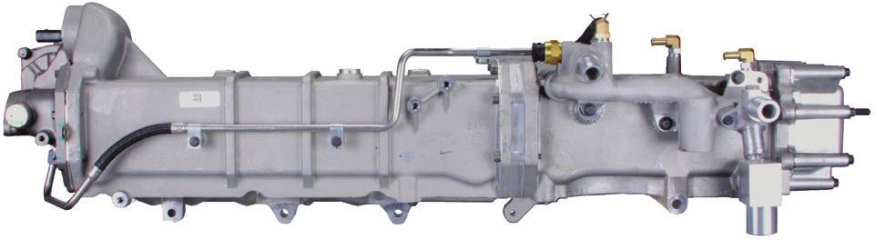
9 2010 EPA, 2013 N13 Engine Aftertreatment System MODULE 2 MODULE 2: EXHAUST GAS RECIRCULATION SYSTEM This module is divided into four subsections: Overview, Components, Exhaust Flow, and Coolant Flow. Overview The Exhaust Gas Recirculation (EGR) System reduces the engine s emission of NOx by circulating cooled, inert exhaust into the combustion chamber. The cooled exhaust gas absorbs some of the heat generated during combustion, which lowers peak exhaust temperatures and decreases NOx formation. Section 1: Overview Section 2: Components Section 3: Exhaust Flow Section 4: Coolant Flow ALTHOUGH THE NOX IN SENSOR IS ENGINE MOUNTED, IT IS NOT USED FOR EGR CONTROL. INSTEAD, THIS SENSOR IS USED AS AN INPUT TO THE AFTERTREATMENT CONTROL MODULE (ACM) TO CONTROL DIESEL EXHAUST FLUID (DEF) INJECTION. Components The EGR System consists of the Engine Throttle Valve, EGR Cooler Assembly, Oxygen Sensor, Temperature Sensors, and EGR Valve. The EGR Valve is mounted to the inlet of the EGR Cooler Assembly and is used to control the flow of exhaust gas through the EGR system. The EGR Valve consists of a motor, two butterfly valves, and an internal position sensor. The ECM uses inputs from the internal position sensor of the EGR Valve to precisely control the EGR Valve motor and position of the butterfly valves. Engine coolant is circulated through the EGR valve to increase the durability of the actuator by preventing overheating. Depending on the production date, a jumper harness my be secured with epoxy to the EGR Valve connector bolted to the top of the EGR Valve. If the EGR Valve connector needs to be disconnected, only do so at the new EGR Valve connector service location. Refer to TSI for service information.. The Coolant Control Valve (CCV) consists of a Coolant Flow Valve and a Coolant Mixer Valve. During operation, the Coolant Flow Valve (CFV) regulates the coolant flow through the Low-Temperature EGR Cooler along with the Low-Pressure Charge-Air-Cooler (LPCAC). The Coolant Mixer Valve (CMV) controls the amount of coolant that passes through the Low-Temperature Radiator (LTR). The Oxygen Sensor (O2S) is a wideband oxygen sensor and is installed in the exhaust pipe in front of the Aftertreatment Fuel Injector. The O2S is used to monitor the oxygen level of the exhaust gas exiting the Low Pressure Turbo. The Engine Throttle Valve (ETV) is mounted to the cylinder head near the front-left side of the engine and is used to restrict intake airflow and assist EGR operation. The ETV consists of a motor, a butterfly valve, and an internal position sensor. The ECM uses inputs from the internal position sensor of the ETV to precisely control the ETV motor and position of the butterfly valve. 7

 Sensor is located at the front of the EGR Cooler Assembly and measures the exhaust gas temperature exiting the EGR cooler.")


10 STUDY GUIDE 2010 EPA, 2013 N13 Engine Aftertreatment System MODULE 2: EXHAUST GAS RECIRCULATION SYSTEM The Engine Coolant Temperature 2 (ECT2) Sensor is mounted to the Low-Tempeature EGR Cooler Manifold and is used to measure the temperature of the coolant being sent to the LPCAC. The Intake Manifold Temperature (IMT) Sensor is located on the Intake Manifold and measures the temperature of charge-air inside of the manifold. The EGR Temperature (EGRT) Sensor is located at the front of the EGR Cooler Assembly and measures the exhaust gas temperature exiting the EGR cooler. The EGR Cooler Assembly is a two-stage heat exchanger mounted to the right side of the engine. The assembly consists of a high-temperature section and a low-temperature section. The high-temperature section is the back half of the EGR Cooler and the low-temperature section is the front half. Engine coolant is used to absorb heat and lower the temperature of exhaust gas as the gases flow through the high and low-temperature sections of the EGR Cooler Assembly. Now that you know what components the EGR System consists of, let s move on to the next section on Exhaust Flow. Click the NEXT button when you re ready to continue. Exhaust Flow During engine operation, EGR flow is controlled by the ECM based on the data it receives from multiple sensor inputs. These inputs include engine load, coolant temperature, manifold temperature, boost pressure, oxygen levels in the exhaust, and various inputs from the Aftertreatment Control Module. When EGR flow is required, the ECM commands the EGR valve to open, allowing exhaust gas from the exhaust manifold to enter the High-Temperature section of the EGR Cooler. As the hot exhaust gas flows through the EGR Cooler Assembly, heat from the gas is transferred to the cooler and then absorbed by engine coolant. The cooled exhaust gas flows from the Low-Temperature EGR Cooler into the mixing duct and then mixes with intake air. The ECM may also command the Engine Throttle Valve to restrict intake air flow and aid in EGR flow. Click the REPLAY button if you d like a review of the Exhaust Flow, or click the NEXT button to move on to Coolant Flow. Coolant Flow As discussed earlier, the EGR Cooler Assembly is divided into two sections: a Low Temperature EGR Cooler section at the front and a High Temperature EGR Cooler section at the back. Coolant from the Rear Coolant Crossover Tube supplies the High Temperature EGR Cooler. After flowing through the High Temperature EGR Cooler, the heated coolant is directed to the EGR Cooler spacer plate and then to a dedicated coolant passage within the Low Temperature EGR Cooler. This passage runs the length of the Low Temperature EGR Cooler and returns the heated coolant from the High-Temperature EGR Cooler to the thermostat housing. 8
11 2010 EPA, 2013 N13 Engine Aftertreatment System MODULE 2 MODULE 2: EXHAUST GAS RECIRCULATION SYSTEM While the Low Temperature EGR Cooler has a dedicated coolant passage that allows the coolant from the High Temperature EGR Cooler to exit to the thermostat housing, the coolant passages in the High and Low Temperature EGR Coolers are independent from each other. The Low Temperature EGR Cooler is supplied with coolant directly from the Water Distribution Housing. After flowing through Low-Temperature EGR Cooler, heated coolant exits through the EGR Cooler Manifold to the Coolant Control Valve. Depending on the temperature of engine coolant, the Coolant Mixer Valve and Coolant Flow Valve are commanded into various states. At low coolant temperatures, the Coolant Mixer Valve bypasses coolant flow past the Low-Temperature Radiator and sends the coolant directly to the Low-Pressure Charge-Air-Cooler. When required, the Coolant Mixer Valve will direct up to 100% of the coolant flow to the LTR for additional cooling. At the same time, the Coolant Flow Valve will regulate the volume of coolant that passing through the Low Temperature EGR Cooler and the LPCAC. The flow minimum is 20% and will increase up to 100% as conditions require. The Y fitting on the Low Temperature EGR Cooler Manifold combines the coolant flow from the CCV and the LTR. Coolant flows from the Y fitting to the back of the Low Temperature EGR Cooler Manifold, passes the Engine Coolant Temperature 2 Sensor, and then is sent to the LPCAC. Lastly, a vent on the Low Temperature EGR Cooler Manifold serves dual purposes: to cool the EGR Valve, and to purge air to the Deaeration Tank. Conclusion This concludes the description of Coolant Flow and brings us to the end of Module 2. Click the NEXT button to continue to Module 3. 9
12 STUDY GUIDE 2010 EPA, 2013 N13 Engine Aftertreatment System NOTES 10


 is located on the right side of the engine and is installed on the Exhaust Back Pressure Valve Housing, downstream of the Exhaust Backpressure Valve.")


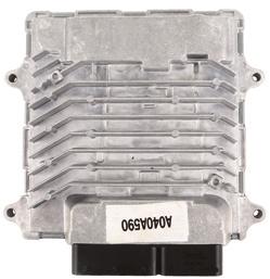
13 2010 EPA, 2013 N13 Engine Aftertreatment System MODULE 3 MODULE 3: AFTERTREATMENT FUEL INJECTION The Aftertreatment Fuel Injection Module is divided into four subsections: Overview, Components, Injection Stage Operation, and Purging Stage Operation. Overview The Aftertreatment Fuel Injection system is used to inject fuel into the exhaust system to aid in aftertreatment regeneration. The fuel, which is injected after the turbochargers, reacts with the aftertreatment system catalysts and causes an increase in exhaust temperature. This increase in exhaust temperature promotes oxidation of the soot trapped within the various components of the Aftertreatment System. Components The components used in the Aftertreatment Fuel Injection System are the Aftertreatment Fuel Dosing Module, Aftertreatment Purge Air valve, Aftertreatment Fuel Injection fuel lines, Aftertreatment Fuel Injector, and the Aftertreatment Control Module. Click the NEXT button to view a description of each component. The Aftertreatment Fuel Dosing Module is mounted on the left side of the engine and contains the Aftertreatment Fuel Shutoff Valve and the Aftertreatment Fuel Pressure 1 Sensor. Filtered, low-pressure fuel is supplied to the Aftertreatment Fuel Dosing Module from the Secondary Fuel Filter Module. The Aftertreatment Purge Air Valve (AFTPAV) is mounted on the left side of the engine and uses vehicle air pressure to purge fuel from the Aftertreatment Fuel Supply lines. The Aftertreatment Fuel Supply Line routes fuel from the Aftertreatment Fuel Dosing Module to the Aftertreatment Fuel Injector. This line is located on the rear of the engine and has very precise length, inside diameter, and tubing thickness specifications. The Aftertreatment Fuel Injector (AFTFI) is located on the right side of the engine and is installed on the Exhaust Back Pressure Valve Housing, downstream of the Exhaust Backpressure Valve. The Aftertreatment Control Module will command the AFTFI ON when injection is needed to aid with DPF Regeneration. A metal gasket, ceramic insulator, and two special high-temperature bolts seal the injector to the Exhaust Back Pressure Valve Housing. To protect the AFTFI s internal components, engine coolant continuously flows through the AFTFI. This coolant is provided by external coolant supply and return lines. The Aftertreatment Control Module, or ACM, is remotely mounted and controls the Aftertreatment Fuel Injection and the Selective Catalyst Reduction, or SCR, Aftertreatment system. The ACM and ECM communicate through two J1939 Controller Area Network (CAN) datalinks, the Private Aftertreatment CAN, and the Public CAN. The ACM and ECM communicate with various components of the aftertreatment system over the Private Aftertreatment CAN datalink. The Public CAN datalink is used by the ACM and ECM for diagnostics, programming, and communications with other modules such as the Body Control Module, Gauge Cluster, and Transmission. Now that you are familiar with the components of the Aftertreatment Fuel Injection System, let s move on to the next section on Injection Stage Operation. Click the NEXT button when you re ready to continue. Section 1: Overview Section 2: Components Section 3: Injection Stage Operation Section 4: Purging Stage Operation 11
14 STUDY GUIDE 2010 EPA, 2013 N13 Engine Aftertreatment System Injection Stage Operation When the ACM has identified that Aftertreatment Fuel Injection is required, it will communicate with the ECM via the Private Aftertreatment CAN datalink to initiate the Aftertreatment Fuel Injection process. The ACM commands the Aftertreatment Fuel Shutoff Valve open, allowing filtered, low-pressure fuel from the Secondary Fuel Filter Module to flow to the AFTFI. With the Aftertreatment Fuel Shutoff Valve open and fuel supplied to the AFTFI, the ACM will command the AFTFI to pulse, injecting fuel into the exhaust stream. Purging Stage Operation When Aftertreatment Fuel Injection is no longer required, the Aftertreatment Purge Air Valve is used to purge out any fuel remaining in the system. With the Aftertreatment Fuel Shutoff Valve closed, both the Aftertreatment Purge Air Valve and the AFTFI are commanded ON allowing vehicle air pressure to pass through the Aftertreatment Purge Air Valve and purge fuel remaining in the system out through the AFTFI. Conclusion This concludes the Navistar training course on the 2010 EPA, 2013 N13 Engine Aftertreatment System. Thank you for your participation. Close this window and return to the Course Grade Book to take the final test. 12
15
16 2010 EPA, 2013 N13 Engine Aftertreatment System
2013 Aftertreatment System with SCR Overview for Technicians Study Guide
 TMT121340 Class Course Code: 8359 2013 Aftertreatment System with SCR Overview for Technicians Study Guide 2013 Aftertreatment System with SCR Study Guide 2013 Navistar, Inc. All rights reserved. All marks
2015 PSI 8.8L LPG Engine Overview. Study Guide. Course Code: 8777
 2015 PSI 8.8L LPG Engine Overview Study Guide Course Code: 8777 1 2015 PSI 8.8L LPG Engine Overview Study Guide 2015 Navistar, Inc. 2701 Navistar Drive, Lisle, IL 60532. All rights reserved. No part of
Study Guide MaxxForce TM 5 Engine Update TMT
 A N AV I S TA R C O M PA N Y MaxxForce TM 5 Engine Update Study Guide TMT-120710 Study Guide MaxxForce TM 5 Engine Update TMT-120710 2007 International Truck and Engine Corporation 4201 Winfield Road,
Course Code: N13 Engine Exhaust Manifold Service Study Guide
 Course Code: 8573 2015 N13 Engine Exhaust Manifold Service Study Guide 2015 Navistar, Inc. 2701 Navistar Drive, Lisle, IL 60532. All rights reserved. No part of this publication may be duplicated or stored
TABLE OF CONTENTS. Foreword...1. Service Diagnosis...2. Safety Information...3. SCR Component Locator Guide...7. Engine Systems...
 DIAGNOSTIC MANUAL I TABLE OF CONTENTS Foreword...1 Service Diagnosis...2 Safety Information...3 SCR Component Locator Guide...7 Engine Systems...13 Engine and Vehicle Features...75 Diagnostic Software
Presented by. Navistar Education 2015
 Presented by Navistar Education 2015 1.2 Overview This course is intended to provide parts specialists with a description of Diesel Exhaust Fluid, or DEF, part number configuration, ordering and distribution
Engine Emission Control 6.7L Diesel
 Page 1 of 6 SECTION 303-08: Engine Emission Control 2011 F-250, 350, 450, 550 Super Duty Workshop Manual DESCRIPTION AND OPERATION Procedure revision date: 03/12/2010 Engine Emission Control 6.7L Diesel
EVERY ALTERNATIVE ISLG Combustion Air and Emission Devices. Why Cooled EGR? 4/23/2013. Why Exhaust Gas Recirculation.
 EVERY ALTERNATIVE. 2007 ISLG Combustion Air and Emission Devices Why Exhaust Gas Recirculation Basic Science NOx (Oxides of Nitrogen) pollution occurs due to high cylinder temperatures during the combustion
TABLE OF CONTENTS. Foreword...1. Service Diagnosis...2. Safety Information...3. Engine Systems...5. Mounting Engine on Engine Stand...
 ENGINE SERVICE MANUAL I TABLE OF CONTENTS Foreword...1 Service Diagnosis...2 Safety Information...3 Engine Systems...5 Mounting Engine on Engine Stand...59 Engine Electrical...71 Down Stream Injection
Table of Contents. Foreword...1. Service Diagnosis...2. Safety Information...3. Engine Systems...5. Mounting Engine on Engine Stand...
 ENGINE SERVICE MANUAL I Table of Contents Foreword...1 Service Diagnosis...2 Safety Information...3 Engine Systems...5 Mounting Engine on Engine Stand...55 Engine Electrical...65 Variable Geometry Turbocharger
Exhaust After-Treatment System. This information covers design and function of the Exhaust After-Treatment System (EATS) on the Volvo D16F engine.
 on the Volvo D16F engine.") Volvo Trucks North America Greensboro, NC USA DService Bulletin Trucks Date Group No. Page 1.2007 258 44 1(6) Exhaust After-Treatment System Design and Function D16F Exhaust After-Treatment System W2005772
Volvo Trucks North America Greensboro, NC USA DService Bulletin Trucks Date Group No. Page 1.2007 258 44 1(6) Exhaust After-Treatment System Design and Function D16F Exhaust After-Treatment System W2005772
2010 EPA 2013 HD-OBD N9 and N10 with SCR Diagnostics for Technicians. Study Guide. Course Code: 8448
 2010 EPA 2013 HD-OBD N9 and N10 with SCR Diagnostics for Technicians Study Guide Course Code: 8448 1 2010 EPA 2013 HD-OBD N9 and N10 with SCR Diagnostics for technicians Study Guide 2014 Navistar, Inc.
TABLE OF CONTENTS. Foreword...1. Service Diagnosis...2. Safety Information...3. Engine Systems...5. Mounting Engine on Engine Stand...
 ENGINE SERVICE MANUAL I TABLE OF CONTENTS Foreword...1 Service Diagnosis...2 Safety Information...3 Engine Systems...5 Mounting Engine on Engine Stand...53 Engine Electrical...63 Cold Start Assist...111
Air Management System Components
 AIR M anagement Sys tem Air Management System Components Air Management System Features Series Sequential The series sequential turbocharger is a low pressure/high pressure design working in series with
2007 MaxxForce TM 11 and MaxxForce 13 Engine Diagnostics
 A N AV I S TA R C O M PA N Y 2007 MaxxForce TM 11 and MaxxForce 13 Engine Diagnostics Study Guide TMT-120802 Study Guide MaxxForce TM 11 and MaxxForce 13 Engine Systems TMT-120802 2008 International Truck
E - THEORY/OPERATION - TURBO
 E - THEORY/OPERATION - TURBO 1995 Volvo 850 1995 ENGINE PERFORMANCE Volvo - Theory & Operation 850 - Turbo INTRODUCTION This article covers basic description and operation of engine performance-related
2010 MaxxForce 11 and 13L Diagnostics
 2010 MaxxForce 11 and 13L Diagnostics Study Guide TMT-121130 Study Guide 2010 MaxxForce 11 and 13L Diagnostics TMT-121130 2011 Navistar, Inc. 4201 Winfield Road, Warrenville, IL 60555. All rights reserved.
Additions, Revisions, or Updates
 1 10 26-13 SUBJECT DATE SPN 3216/FMI 16 and 18 October 2013 Additions, Revisions, or Updates Publication Number / Title Platform Section Title Change DDC-SVC-MAN-0084 GHG14 DD Platform SPN 3216/FMI 16
Automotive Fuel and Emissions Control Systems 4/E
 Automotive Fuel and Emissions Control Systems 4/E Opening Your Class KEY ELEMENT Introduce Content Motivate Learners State the learning objectives for the chapter or course you are about to cover and explain
Heavy-Duty Engine Lifting Bracket Installation. Study Guide. Course Code: 8803
 Heavy-Duty Engine Lifting Bracket Installation Study Guide Course Code: 8803 2015 Navistar, Inc. 2701 Navistar Drive, Lisle, IL 60532. All rights reserved. No part of this publication may be duplicated
INTRODUCING CE SERIES WITH CUMMINS ISB6.7
 INTRODUCING CE SERIES WITH CUMMINS ISB6.7 OVERVIEW 1. Introducing the Cummins ISB6.7 2. Cummins ISB6.7 Features, Technology and Enhancements 3. The CE Engine Portfolio INTRODUCING THE CUMMINS ISB6.7 What
Additions, Revisions, or Updates
 1 11 19-13 SUBJECT DATE SPN 3216/FMI 2, 18 GHG14 (MCM2.1) November 2013 Additions, Revisions, or Updates Publication Number / Title Platform Section Title Change SPN 3216/FMI 2 DDC-SVC-MAN-0084 GHG14 DD
Table of Contents. Foreword Service Diagnosis Safety Information Engine Systems Mounting Engine on Engine Stand...
 ENGINE SERVICE MANUAL I Table of Contents Foreword... 1 Service Diagnosis... 2 Safety Information... 3 Engine Systems... 5 Mounting Engine on Engine Stand...59 EVRT Electronically Controlled Turbocharger...67
Intake and Exhaust System, Design and Function
 Volvo Trucks North America Greensboro, NC USA DService Bulletin Trucks Date Group No. Page 12.2006 250 34 1(6) Intake and Exhaust System Design and Function D13F Intake and Exhaust System, Design and Function
AFC 12917: Deaeration Tank Hose Rerouting. Study Guide TMT Course Code: 8438
 AFC 12917: Deaeration Tank Hose Rerouting Study Guide TMT121373 Course Code: 8438 2013 Navistar, Inc. 2701 Navistar Drive, Lisle, IL 60532. All rights reserved. No part of this publication may be duplicated
Internal Combustion Engines
 Emissions & Air Pollution Lecture 3 1 Outline In this lecture we will discuss emission control strategies: Fuel modifications Engine technology Exhaust gas aftertreatment We will become particularly familiar
Exhaust System - 2.2L Diesel
 Page 1 of 9 Published: Mar 8, 2007 Exhaust System - 2.2L Diesel COMPONENT LOCATION - WITH DIESEL PARTICULATE FILTER Item Part Number Description 1 Exhaust manifold (ref only) 2 Pressure differential sensor
TSI : Crankcase Oil Separator Housing Replacement. Study Guide TMT Course Code: 8443
 TSI 13-12-04: Crankcase Oil Separator Housing Replacement Study Guide TMT121379 Course Code: 8443 1 TSI-13-12-04: Crankcase Oil Separator Housing Replacement Study Guide 2013 Navistar, Inc. 2701 Navistar
Additions, Revisions, or Updates
 1 SUBJECT SPN 3216 (ACM) (GHG17) SPN 3217 (ACM) (GHG17) DATE March 2017 Additions, Revisions, or Updates Publication Number / Title Platform Section Title Change DDC-SVC-MAN-0193 GHG17 Medium Duty SPN
This information covers the design and function of the intake and exhaust systems for the Volvo D16F engine.
 Volvo Trucks North America Greensboro, NC USA Intake and Exhaust System DService Bulletin Trucks Date Group No. Page 2.2007 250 35 1(6) Intake and Exhaust System Design and Function D16F W2005773 This
EMISSION CONTROL (AUX. EMISSION CONTROL DEVICES) H4DOTC
 H4DOTC") EMISSION CONTROL (AUX. EMISSION CONTROL DEVICES) H4DOTC SYSTEM OVERVIEW 1. System Overview There are three emission control systems, which are as follows: Crankcase emission control system Exhaust emission
EMISSION CONTROL (AUX. EMISSION CONTROL DEVICES) H4DOTC SYSTEM OVERVIEW 1. System Overview There are three emission control systems, which are as follows: Crankcase emission control system Exhaust emission
CUMMINS ENGINE ISX15 ISX CM2250 Service Workshop Manual
 Instant Manual Download CUMMINS ENGINE ISX15 ISX CM2250 Service Workshop Manual Download Here CUMMINS ENGINE ISX15 Service Workshop Repair Shop Manual PLEASE NOTE: YOU NEED TO BE CONNECTED TO THE INTERNET
Additions, Revisions, or Updates
 4 68-12 1 4 68-12 SUBJECT DATE SPN 5018/FMI 18 - GHG14 September 2012 Additions, Revisions, or Updates Publication Number / Title Platform Section Title Change DDC-SVC-MAN-0084 DD Platform SPN 5018/FMI
Cummins engine Signature ISX QSX15 Service Workshop Shop Repair Manual - PDF Service Manual
 Cummins engine Signature ISX QSX15 Service Workshop Shop Repair Manual - PDF Service Manual DOWNLOAD HERE "Cummins engine Signature ISX QSX15 Service Workshop Shop Repair Manual - PDF Service Manual Signature
TNV Series Common Rail. Final Tier 4 19kW to 56kW WATER-COOLED DIESEL ENGINES. EPA Tier 4 (19-56kW) EU Stage IIIB (37-56kW)
 EU Stage IIIB (37-56kW)") Final Tier 4 19kW to 56kW WATER-COOLED DIESEL ENGINES TNV Series Common Rail EPA Tier 4 (19-56kW) EU Stage IIIB (37-56kW) TNV SERIES COMMON RAIL ENGINES EPA TIER 4 (19-56kW) EU Stage IIIB (37-56kW) * DPF
Final Tier 4 19kW to 56kW WATER-COOLED DIESEL ENGINES TNV Series Common Rail EPA Tier 4 (19-56kW) EU Stage IIIB (37-56kW) TNV SERIES COMMON RAIL ENGINES EPA TIER 4 (19-56kW) EU Stage IIIB (37-56kW) * DPF
CANDO Diagnostic List Cummins_v8.27
 CANDO Diagnostic List Cummins_v8.27 Remark: 1. : means that the system has this function 2. - : means that the system does not have this function 3.compared with the last version, the new added function
EMISSION CONTROL (AUX. EMISSION CONTROL DEVICES) H4SO
 H4SO") EMISSION CONTROL (AUX. EMISSION CONTROL DEVICES) H4SO SYSTEM OVERVIEW 1. System Overview There are three emission control systems, which are as follows: Crankcase emission control system Exhaust emission
EMISSION CONTROL (AUX. EMISSION CONTROL DEVICES) H4SO SYSTEM OVERVIEW 1. System Overview There are three emission control systems, which are as follows: Crankcase emission control system Exhaust emission
DD13 FIRE AND EMERGENCY
 ENGINE DD13 FIRE AND EMERGENCY DETROIT DIESEL ENGINES: DEMAND IT ALL. Detroit Diesel has been the industry standard in the custom chassis fire truck business for more than three decades. Through the years,
DTC P20EE, P249D, P249E, or P2BAD
 Page 1 of 7 Document ID: 2614257 DTC P20EE, P249D, P249E, or P2BAD Diagnostic Instructions Perform the Diagnostic System Check - Vehicle prior to using this diagnostic procedure. Review Strategy Based
512 HO M285 Engine (FrechW) Maybach Engine M285
 Maybach Engine M285") 512 HO M285 Engine (FrechW) 08-06-03 Maybach Engine M285 These technical training materials are current as of the date noted on the materials, and may be revised or updated without notice. Always check
512 HO M285 Engine (FrechW) 08-06-03 Maybach Engine M285 These technical training materials are current as of the date noted on the materials, and may be revised or updated without notice. Always check
THE StarSCAN FLASH FILES FOR THIS BULLETIN MUST BE RETRIEVED FROM THE INTERNET. StarSCAN SOFTWARE LEVEL MUST BE AT RELEASE 9.02 OR HIGHER.
 NUMBER: 18-035-08 GROUP: Vehicle Performance DATE: September 13, 2008 This bulletin is supplied as technical information only and is not an authorization for repair. No part of this publication may be
m b e E M I S S I O N S E N G I N E
 m b e 4 0 0 0 2 0 0 7 E M I S S I O N S E N G I N E We re DRIVING TECHNOLOGY. Detroit Diesel and Mercedes-Benz have over 150 combined years of experience designing, testing and manufacturing diesel engines.
EGR System, Design and Function. This information covers design and function of the Exhaust Gas Recirculation (EGR) system on a Volvo D16F engine.
 system on a Volvo D16F engine.") Volvo Trucks North America Greensboro, NC USA DService Bulletin Trucks Date Group No. Page 12.2006 254 59 1(6) EGR System Design and Function D16F EGR System, Design and Function W2005836 This information
Volvo Trucks North America Greensboro, NC USA DService Bulletin Trucks Date Group No. Page 12.2006 254 59 1(6) EGR System Design and Function D16F EGR System, Design and Function W2005836 This information
Additions, Revisions, or Updates
 1 12 02-12 SUBJECT DATE Test E - Three-Filter Fuel System December 2012 Additions, Revisions, or Updates Publication Number / Title Platform Section Title Change DDC-SVC-MAN-0084 DD Platform Test E - Three-Filter
OCTOBER 2015 DLTN9501A-ILT
 OCTOBER 2015 DLTN9501A-ILT This book is designed for instructional use only for authorized Nissan North America, Inc. and Nissan dealer personnel. For additional information contact: Nissan North America,
SPN 4364/FMI 17 - GHG17 SPN /FMI 16 - GHG17 SPN /FMI 14 - GHG17 SPN 3216/FMI 16 - GHG17 SPN 3216/FMI 18 - GHG17 SPN 3217/FMI 2 - GHG17
 11 29-16 1 11 29-16 SUBJECT SPN 4364 (ACM) (GHG17) SPN 520371 (ACM) (GHG17) SPN 520372 (ACM) (GHG17) SPN 3216 (ACM) (GHG17) SPN 3217 (ACM) (GHG17) SPN 3226 (ACM) (GHG17) SPN 3227 (ACM) (GHG17) Diagnostic
ENGINE TECHNOLOGY. Bobcat Engine_B _ _EN_reworked.indd 1
 ENGINE TECHNOLOGY Bobcat Engine_B4459500_01-2015_EN_reworked.indd 1 1/30/2015 10:07:51 AM A COMPANY THAT S GROWING WITH SOCIETY Bobcat prides itself on innovations that shape the future. For decades, we
Engine Systems. Basic Engine Operation. Firing Order. Four Stroke Cycle. Overhead Valves - OHV. Engine Design. AUMT Engine Systems 4/4/11
 Advanced Introduction Brake to Automotive Systems Diagnosis Service and Service Basic Engine Operation Engine Systems Donald Jones Brookhaven College The internal combustion process consists of: admitting
DETROIT Engines DD15 DD13 DD16
 DETROIT Engines DD13 DD15 DD16 TECHNICAL SPECIFICATIONS 350-470 Horsepower 1250-1650 lb-ft Torque DISPLACEMENT 12.8 Liters DD13 Specifications Configuration Inline 6 Cylinder Displacement 781 cu. in. (12.8
COOLING SYSTEM - V8. Cooling system component layout DESCRIPTION AND OPERATION
 Cooling system component layout 26-2-2 DESCRIPTION AND OPERATION 1 Heater matrix 2 Heater return hose 3 Heater inlet hose 4 Heater inlet pipe 5 Throttle housing 6 Connecting hose 7 Throttle housing inlet
Additions, Revisions, or Updates
 1 9 19-13 SUBJECT DATE SPN 102/FMI 18 - GHG14 MCM2.1 October 2013 Additions, Revisions, or Updates Publication Number / Title Platform Section Title Change DDC-SVC-MAN-0084 DD Platform SPN 102/FMI 18 Complete
EURO 4-5 Diesel Exhaust Pollutant. After-Threatment
 EURO4-5 Common Rail EURO 4-5 Diesel Exhaust Pollutant After-Threatment 1 Exhaust gas recirculation EGR fundamentals: AFR: Air to Fuel Ratio. This parameter is used to define the ratio between fuel (petrol,
P Fuel Volume Regulator Control Circuit P Fuel Volume Regulator Control Circuit Range/Performance P Fuel Volume Regulator Control
 P0001 - Fuel Volume Regulator Control Circuit P0002 - Fuel Volume Regulator Control Circuit Range/Performance P0003 - Fuel Volume Regulator Control Circuit Low P0004 - Fuel Volume Regulator Control Circuit
EMISSION WARRANTIES FOR MTU ON-HIGHWAY APPLICATIONS
 2017 EMISSION WARRANTIES FOR MTU ON-HIGHWAY APPLICATIONS Page 1 of 7 1 FEDERAL EMISSION CONTROL WARRANTY STATEMENT 1.1 Emissions Warranty MTU America Inc. (MTU) warrants to the owner ( Owner ) of engines
SPN 4364 (ACM)(EPA10); SPN 4364 (ACM)(GHG14) January Publication Number / Title Platform Section Title Change SPN 4364/FMI 18 - EPA10
(EPA10); SPN 4364 (ACM)(GHG14) January Publication Number / Title Platform Section Title Change SPN 4364/FMI 18 - EPA10") 01 01-18 1 01 01-18 SUBJECT DATE SPN 4364 (ACM)(EPA10); SPN 4364 (ACM)(GHG14) January 2018 Additions, Revisions, or Updates Publication Number / Title Platform Section Title Change DDC-SVC-MAN-0084 DD
01 01-18 1 01 01-18 SUBJECT DATE SPN 4364 (ACM)(EPA10); SPN 4364 (ACM)(GHG14) January 2018 Additions, Revisions, or Updates Publication Number / Title Platform Section Title Change DDC-SVC-MAN-0084 DD
ASSEMBLY/INSTALLATION INSTRUCTIONS
 ASSEMBLY/INSTALLATION INSTRUCTIONS AURORA 3000 & 4000 SCORPION TURBO SYSTEM NOTICE: The engine oil must be changed any time the turbocharger is removed from the engine. The passages in the block underneath
DETROIT DD13 ENGINE MOTORCOACH MODEL
 DETROIT DD13 ENGINE MOTORCOACH MODEL FROM 410-450 Horsepower FROM 1450-1650 lb-ft Torque DISPLACEMENT 12.8 Liters DD13 : WITH SCR EMISSIONS TECHNOLOGY. How SCR Emissions Technology Works Selective Catalytic
How does Exhaust Gas Recirculation work?
 How does Exhaust Gas Recirculation work? Words: Dr. Johannes Kech Pictures: MTU Tags/Keywords Nitrogen oxide (NOX) emissions can be reduced using internal engine technology by cooling some of the exhaust
Variable Nozzle Turbocharger (VNT)
") Variable Nozzle Turbocharger (VNT) Figure 2-5 VNT Turbocharger Figure 2-6 Cut Away View of the Vanes The results of being able to adjust like this are as follow. See Figure 2-5 and see Figure 2-6. Enhanced
Variable Nozzle Turbocharger (VNT) Figure 2-5 VNT Turbocharger Figure 2-6 Cut Away View of the Vanes The results of being able to adjust like this are as follow. See Figure 2-5 and see Figure 2-6. Enhanced
Additions, Revisions, or Updates
 1 9 14-14 SUBJECT DATE SPN 3563 (MCM) (GHG14) September 2014 Additions, Revisions, or Updates Publication Number / Title Platform Section Title Change DDC-SVC-MAN-0084 GHG14 DD Platform SPN 3563/FMI 21
2. Air Line AIR LINE FUEL INJECTION (FUEL SYSTEM) A: GENERAL B: MANIFOLD ABSOLUTE PRESSURE SENSOR FU(H4DOTC)-3
 A: GENERAL B: MANIFOLD ABSOLUTE PRESSURE SENSOR FU(H4DOTC)-3") W1860BE.book Page 3 Tuesday, January 28, 2003 11:01 PM 2. Air Line A: GENERAL The air filtered by the air cleaner enters the throttle body where it is regulated in the volume by the throttle valve and
W1860BE.book Page 3 Tuesday, January 28, 2003 11:01 PM 2. Air Line A: GENERAL The air filtered by the air cleaner enters the throttle body where it is regulated in the volume by the throttle valve and
Chapter 20 OBD-II Diesel Monitors
 Light Vehicle Diesel Engines First Edition Chapter 20 OBD-II Diesel Monitors LEARNING OBJECTIVES (1 of 2) 20.1 Prepare for the Light Vehicle Diesel Engine (A9) ASE certification fuel system diagnosis and
NUMBER: S.M. REF.: Listed in Table ENGINE: EPA07 Series 60 DATE: October 2012 SUBJECT: REFERENCES TO THE TURBOCHARGER PURGE ROUTINE
 NUMBER: 10 01 12 S.M. REF.: Listed in Table ENGINE: EPA07 Series 60 DATE: October 2012 SUBJECT: REFERENCES TO THE TURBOCHARGER PURGE ROUTINE ADDITIONS, REVISIONS, OR UPDATES Publication Number Platform
Tier 4 overview. 1. Emission regulations 2. Product overview 3. Engine layout. Content. Vico de Bres Customer Service Department Yanmar Europe B.V.
 Tier 4 overview Date 2 April 2013 Vico de Bres Customer Service Department Yanmar Europe B.V. Content 1. Emission regulations 2. Product overview 3. Page1 Emission regulations Tier 4 Page2 USA EPA-Tier
Engine Diagrams
 100-002 Engine Diagrams Engine Views The illustrations that follow show the locations of the major external engine components, the filters, and other service and maintenance points. Some external components
DD13 Engine Fire and Emergency Model
 DD13 Engine Fire and Emergency Model FROM 470-525 Horsepower FROM 1650-1850 lb-ft Torque DISPLACEMENT 12.8 Liters DETROIT DD13 ENGINE IS EXCLUSIVE TO PIERCE CUSTOM APPARATUS. DD13: WITH SCR EMISSIONS TECHNOLOGY.
US & CANADA VOLVO ENGINE EQUIPPED VEHICLE EMISSIONS COMPONENTS COVERAGE 60 MONTHS/100K MILES Affects: VN, VHD Related: Updated: April 5, 2016
 875001 US & CANADA VOLVO ENGINE EQUIPPED VEHICLE EMISSIONS COMPONENTS COVERAGE 60 MONTHS/100K MILES Affects: VN, VHD Related: Updated: April 5, 2016 Note: PDF files are not official documents and serve
FROM DISPLACEMENT FROM Liters. lbs-ft Torque. Horsepower C U S T O M E R B R O C H U R E
 E N G I N E DD15 FROM 455-560 Horsepower FROM 1550-1850 lbs-ft Torque DISPLACEMENT 14.8 Liters C U S T O M E R B R O C H U R E Demand economy You will realize up to a 5 percent fuel economy improvement.*
eparts Guide Table of Contents
 eparts Guide Table of Contents General eparts Topics: Navigating eparts eparts Catalog Features and Functions DD Engine Platform and MBE Engine Catalog Instruction Aftertreatment Systems Overview Full
Additions, Revisions, or Updates
 1 SUBJECT DATE Parked Regeneration October 2018 Additions, Revisions, or Updates Publication Number / Title Platform Section Title Change DDC-SVC-MAN-0190 GHG17 DD Platform Parked Regeneration DDC-SVC-MAN-0083
GF07.16-P-9997OGG Overview of system components for common rail diesel injection (CDI)
") GF07.16-P-9997OGG Overview of system components for common rail diesel injection (CDI) 19.12.2016 Engine 642.8 in model 164.1 Engine 642.8 in model 164.8 Engine 642.8 in model 251.0 Engine 642.8 in model
GF07.16-P-9997OGG Overview of system components for common rail diesel injection (CDI) 19.12.2016 Engine 642.8 in model 164.1 Engine 642.8 in model 164.8 Engine 642.8 in model 251.0 Engine 642.8 in model
 Page 1 of 9 303-01C Engine 6.0L Diesel 2004 F-Super Duty 250-550/Excursion DESCRIPTION AND OPERATION Procedure revision date: 08/06/2003 Engine Printable View Engine Description The 6.0L diesel engine
IK : High-Pressure Turbocharger Replacement. Study Guide. Course Code: 8472
 IK1200938: High-Pressure Turbocharger Replacement Study Guide Course Code: 8472 1 IK1200938: High-Pressure Turbocharger Replacement Study Guide 2013 Navistar, Inc. 2701 Navistar Drive, Lisle, IL 60532.
Fuel and exhaust systems 4A 21
 Fuel and exhaust systems 4A 21 15.40 Unscrew the union nuts and disconnect the fuel feed and return hoses from the manifold 41 Disconnect the injector wiring harness connector and the vacuum hose from
 Page 1 of 12 Section 2.3 N2 Electronic Unit Injector The N2 Electronic Unit Injector (EUI) is a lightweight, compact unit that injects diesel fuel directly into the combustion chamber. See Figure "N2 Electronic
Additions, Revisions, or Updates
 1 8 22-13 SUBJECT DATE Water Manifold Assembly August 2013 Additions, Revisions, or Updates Publication Number / Title Platform Section Title Change Installation of the DD13 EGR Cooler Water DDC-SVC-MAN-0081
!"#$%&'$()*&$+,-$%&.$()*&$/01$#,23,# 43)"$)353,2$6"+3,
*&$+,-$%&.$()*&$/01$#,23,# 43)$)353,2$6+3,") 0#*?36#& 0#(7$8)9-:$;*.!"#$%&'$()*&$+,-$%&.$()*&$/01$#,23,# 43)"$)353,2$6"+3, Design and function For Volkswagen, new and further development of engines with direct petrol injection is an important
0#*?36#& 0#(7$8)9-:$;*.!"#$%&'$()*&$+,-$%&.$()*&$/01$#,23,# 43)"$)353,2$6"+3, Design and function For Volkswagen, new and further development of engines with direct petrol injection is an important
 Page 1 of 6 2008 Ford Pickup 6.4L Eng F250 Super Duty ENGINE CONTROLS - DESCRIPTION AND OPERATION - F250-F550 SUPER DUTY 6.4L (DIESEL ) FUEL SYSTEM The fuel system includes the following: low pressure
Future of Trucking Symposium 2010 Engine & Emissions Technology
 Future of Trucking Symposium 2010 Engine & Emissions Technology Winnipeg, MB Tim Tindall Director Component Sales North America February 2010 Security Classification Line 1 Daimler Commitment to SCR Strategic
HVAC System: Engine Cooling, Controls and Communication
 Course #S-AC07-04.01VCT HVAC System: Engine Cooling, Controls and Communication Participant Guide Revised: 01/24/11 Copyright 2011, General Motors Company, All Rights Reserved Caution Danger: In order
Redefining Efficiency B6.7 For Truck Applications.
 Redefining Efficiency. 2017 B6.7 For Truck Applications. Redefining Efficiency. When you say the word efficiency to anyone in the trucking industry, the conversation immediately turns to fuel economy for
Trucks. Group 28 MID 128 Fault Code Guide 2007 Emissions VN, VHD VERSION2, VT PV
 Service Manual Trucks MID 128 Fault Code Guide 2007 Emissions VN, VHD VERSION2, VT PV776-20184635 Foreword The descriptions and service procedures contained in this manual are based on designs and methods
Economic and Social Council
 United Nations ECE/TRANS/WP.29/2011/126 Economic and Social Council Distr.: General 29 August 2011 Original: English Economic Commission for Europe Inland Transport Committee World Forum for Harmonization
UENR4504 January Troubleshooting. 854F-E34TA Industrial Engine. JU (Engine) This document has been printed from SPI2.
 This document has been printed from SPI2.") UENR4504 January 2015 Troubleshooting 854F-E34TA Industrial Engine JU (Engine) Important Safety Information Most accidents that involve product operation, maintenance and repair are caused by failure to
UENR4504 January 2015 Troubleshooting 854F-E34TA Industrial Engine JU (Engine) Important Safety Information Most accidents that involve product operation, maintenance and repair are caused by failure to
Cylinder Performance Analyzer Tool Training Program Study Guide
 TMT - 121246 CLASS COURSE CODE: D1202 FIRST EDITION, FEBRUARY 2012 Cylinder Performance Analyzer Tool Training Program Study Guide Cylinder Performance Analyzer STUDY GUIDE 2012 Navistar, Inc. 2701 Navistar
Pressure transmitter CAN SAE J1939 DST P92C
 Operation guide Pressure transmitter CAN SAE J1939 DST P92C ia.danfoss.com Table of contents Contents 1. General information... 2 1.1 Contact... 2 1.2 General... 2 1.3 CAN Interface... 3 2. Specifications...
Engine Cooling. Cooling System Component Layout. https://myvpn.dealerconnection.com/extdealerlrprod/xml/parsexml.jsp,danainfo=gtr.fran...
 Page 1 of 5 Published : Apr 28, 2004 Engine Cooling Cooling System Component Layout Item Part Number Description 1 - Heater hose, inlet and outlet 2 - Heater hose, inlet and outlet for vehicles with rear
SECTION D Engine 6.0L Diesel
 303-01D-i Engine 6.0L Diesel 303-01D-i SECTION 303-01D Engine 6.0L Diesel CONTENTS PAGE DESCRIPTION AND OPERATION Engine... 303-01D-2 303-01D-2 Engine 6.0L Diesel 303-01D-2 DESCRIPTION AND OPERATION Engine
Technological breakthrough for Scania: Euro 5 without aftertreatment or fuel penalty
 PRESS info P07901EN / Per-Erik Nordström 5 September 2007 Technological breakthrough for Scania: Euro 5 without aftertreatment or fuel penalty As the first heavy vehicle manufacturer, Scania achieves Euro
EMISSION CONTROL (AUX. EMISSION CONTROL DEVICES) H6DO
 H6DO") EMISSION CONTROL (AUX. EMISSION CONTROL DEVICES) H6DO SYSTEM OVERVIEW 1. System Overview There are three emission control systems, which are as follows: Crankcase emission control system Exhaust emission
EMISSION CONTROL (AUX. EMISSION CONTROL DEVICES) H6DO SYSTEM OVERVIEW 1. System Overview There are three emission control systems, which are as follows: Crankcase emission control system Exhaust emission
Section 10 Chapter 6
 Section 10 Chapter 6 24 Valve, 8.3 Liter Engine Identification Note: All coding used in the 8.3 Liter and 9 Liter engine manuals are Cummins engine codes. These engine codes have no meaning to New Holland
Additions, Revisions, or Updates
 01 04-15 1 01 04-15 SUBJECT DATE SPN 3464/ FMI 16, 18 (MCM) (GHG14) January 2015 Additions, Revisions, or Updates Publication Number / Title Platform Section Title Change DDC-SVC-MAN-0084 DD Platform SPN
Perfectly Adapted. ISL Euro 6 Diesel Engine PS
 ISL Euro 6 Diesel Engine 280-380PS The SCR aftertreatment system used at Euro 5 has been updated by Cummins Emission Solutions. For Euro 6 the compact design incorporates a diesel particulate filter to
OBD-II Diagnostic Powertrain (P) Trouble Codes
 Trouble Codes") OBD-II Diagnostic Powertrain (P) Trouble Codes Please use our new & improved search engine to find information on your trouble codes. Search Now! This list contains standard diagnostic trouble codes (DTC
OBD-II Diagnostic Powertrain (P) Trouble Codes Please use our new & improved search engine to find information on your trouble codes. Search Now! This list contains standard diagnostic trouble codes (DTC
Table of Contents Engine Introduction
 Table of Contents Subject Page New 6-Cylinder Engines for 2007...............................3 New Engine Designations.......................................4 N54 Overview..................................................6
Federal and California Emissions Warranties Parts List
 Emissions warranties are state specific. Refer to the years/miles 1 columns below as follows: A Minimum coverage for all vehicles in all states. B Vehicles registered and normally operated in California,
The 2.0L FSI Turbocharged Engine Design and Function Self-Study Program Course Number
 www.golfmkv.com The 2.0L FSI Turbocharged Engine Design and Function Self-Study Program Course Number 821503 www.golfmkv.com Volkswagen of America, Inc. Volkswagen Academy Printed in U.S.A. Printed 08/2005
EXHAUST SYSTEM AND INTAKE MANIFOLD
 EXHAUST SYSTEM AND INTAKE MANIFOLD 11-1 EXHAUST SYSTEM AND INTAKE MANIFOLD CONTENTS page GENERAL INFORMATION... 1 SERVICE PROCEDURES... 4 page TORQUE SPECIFICATION... 13 EXHAUST SYSTEMS The exhaust systems
Combustion process Emission cleaning Fuel distribution Glow plugs Injectors Low and high pressure pumps
 Page 1 of 16 S60 (-09), 2004, D5244T, M56, L.H.D, YV1RS799242356771, 356771 22/1/2014 PRINT Combustion process Emission cleaning Fuel distribution Glow plugs Injectors Low and high pressure pumps Fuel
ENGINE INTAKE SYSTEM GENERAL 1. ENGINE INTAKE SPECIFICATIONS. 1) Specifications
 Specifications") 04-3 GENERAL 1. ENGINE INTAKE SPECIFICATIONS 1) Specifications Element Type Service Interval Dry-Element Type - Initial cleaning: 5,000 km, Clean or change every 10,000 km as required. However, change
04-3 GENERAL 1. ENGINE INTAKE SPECIFICATIONS 1) Specifications Element Type Service Interval Dry-Element Type - Initial cleaning: 5,000 km, Clean or change every 10,000 km as required. However, change