Return-Suction Filters E 158 E 198 E 248. Tank top mounting Connection up to -20 SAE Nominal flow rate up to 66 gpm us
|
|
|
- Baldwin Fowler
- 5 years ago
- Views:
Transcription


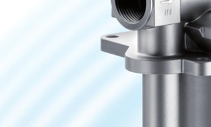


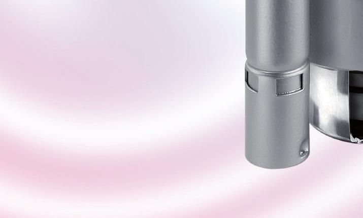

1 Return-Suction Filters E 58 E 98 E 48 Tank top mounting Connection up to - SAE Nominal flow rate up to gpm.9-7us
2 Description Application For operation in units with hydrostatic drives, when the return flow is under all operating conditions higher than the oil flow of the feed pump. Performance features Protection against wear: Suction filter function: Return filter function: By means of filter elements that, in full-flow filtration, meet even the highest demands regarding cleanliness classes. Because of the %-filtration of the suction flow, no dirt can get into the feed pump. By means of full-flow filtration in the system return, the pumps above all are protected from dirt particles remainning in the system after assembly, repairs or which are generated by wear or enter the system from outside. A The emergency-suction valve (4) with 5 µm protection strainer (5) supplies the feed pump in case of a short term of lack of oil. During normal operation, a lack of oil may definitely not occur (refer to Design section). Emergency-suction (schematic): AUS /OUT B / B Functional characteristics The hydraulic oil returning from the circuit (A) passes the filter element (), is pressurized by a 7.3 psi check valve () and supplied to the feed pump (B). The surplus oil flows filtered over the integral check valve into the reservoir. As the feed pump is always fed with pressurized oil, the risk of cavitation is minimized and full performance is available even during the critical cold start phase. An integral pressure relief valve (3) prevents too high back pressure and protects the shaft seals against damages. As this valve leads the oil directly into the tank there is no direct connection between the return line (A) and the connection of the feed pump (B) (no bypass valve function). Function (schematic): A AUS / OUT B / B Start up / Deaeration For units with emergency-suction valve and protection strainer the start up set E 98.7 can be used to de-aerate the hydraulic system at first start up or at start up after repair; hereby the immediate supply of the feed pump with hydraulic oil is guaranteed. For all other types, deaerating instructions published by the manufacturers of hydraulic drives must be observed. 3 Filter maintenance By using a clogging indicator the correct moment for maintenance is indicated and guarantees therefore the optimum utilization of the filter elements. Filter elements Flow direction from center to the outside. The star-shaped pleating of the filter material results in: large filter surfaces low pressure drop high dirt-holding capacities long service life Dirt deposits are entirely removed when the element is changed and cannot re-enter the tank. Accessories Electrical and optical clogging indicators are available. Dimensions and technical data see catalog sheet..
3 Layout General In machines with a hydrostatic drive and combined working hydraulic system, return-suction filters replace the suction or pressure filters previously required for the feed pump of the closed-loop hydrostatic drive circuit as well as the return filter for the open-loop working hydraulic circuit. While each circuit operates independently with separate filters, the combination of the two circuits via the return-suction filter causes interaction between the circuits. If the design criteria described below are taken into account, you can take full advantage of the benefits provided by the return-suction filter concept, thus making sure that your system performs reliably even under extreme operating conditions. Required return flow in the system In order to maintain a precharging pressure of approx. 7.3 psi at the intake of the feed pump, the return flow must exceed the suction flow under any operating condition: Special feature: Versions with hole (Ø. inch) in the pressurizing valve: at least 5.3 gpm of excess flow Permitted feed pump flow rate at operating temperature (ν < 8 SUS, rpm=max): feed pump flow rate <.5 x rated return flow according to column of selection table at cold start-up (ν < 435 SUS, rpm =. min - ): feed pump flow rate <. x rated return flow according to column of selection table Please contact us if your system operates with higher flow rates than stated above. Flow velocity in the connecting lines Flow velocity in the return lines 4.8 ft/s Flow velocity in the suction lines 4.9 ft/s Suggested circuit layouts A) The leakage oil of the hydrostatic drive is routed across the filter. Drain oil to filter Working hydraulics The entire dirt produced in the hydrostatic drive by abrasion is filtered out immediately and is thus not taken in by the pump of the open-loop circuit. This circuit layout is always recommended if the return flow only slightly exceeds the suction flow, i.e. if there is a risk that the 7.3 psi precharging pressure cannot be maintained. B) The drain oil of the hydrostatic drive is not routed across the filter but is discharged directly into the tank. B Working hydraulics A P Permitted pressure in the suction lines At cold start up (ν < 435 SUS, rpm =. min - ): feed pump flow rate <. x rated return flow. The pressure loss in the suction lines must not exceed 5.8 psi. Backpressures in system return lines If drain oil from the hydrostatic drive is routed across the filter in addition to the flow of the open-loop circuit, the following has to be observed in order to protect the shaft seals: permitted leakage oil pressure for a given viscosity and speed (manufacturer s specifications!) pressure loss caused by the leakage oil pipes pressure loss caused by the oil cooler used backpressure of the filter for a given flow rate or kinematic viscosity (refer to pressure loss diagrams) Depending on the application, the use of a cooler bypass valve is recommended. Generously sized drain oil pipes are also of advantage. Filter fineness grades With the filter fineness grades available, the following oil cleanliness according to ISO 44 can be achieved: EX: 8/5/... 4//7 EX: /7/... 7/4/ Even with the EX filter fineness grade, the requirements specified by manufacturers of hydrostatic drives are sometimes exceeded significantly. If components requiring a still better oil purity are used, we recommend the EX filter fineness grade. Drain oil to tank This circuit layout has the advantage that drain oil pressures are comparatively low. B A P
4 Characteristics Nominal flow rate Up to gpm in return line (see Selection Chart, column ) Up to 33 gpm feed pump flow rate (see Layout) The nominal flow rates indicated by ARGO-HYTOS are based on the following features: closed by-pass valve at ν 93 SUS element service life >, operating hours at an average fluid contamination of.7 g per gpm flow volume flow velocity in the return lines 4.8 ft/s flow velocity in the suction lines 4.9 ft/s Connection Threaded ports according to SAE standard J54. Sizes see Selection Chart, column and 7 (other port threads on request) Filter fineness µm(c)... µm(c) β-values according to ISO 889 (see Selection Chart, column 4 and diagram Dx) Dirt-holding capacity Values in g test dust ISO MTD according to ISO 889 (see Selection Chart, column 5) Hydraulic fluids Mineral oil and biodegradable fluids (HEES and HETG, see info-service.). Temperature range - F... + F (temporary - 4 F F) Viscosity at nominal flow rate at operating temperature: ν < 8 SUS as starting viscosity: ν max = 435 SUS at initial operation: The recommended starting viscosity can be read from the diagram D (pressure drop as a function of the kinematic viscosity) as follows: Find the 7 % p of the cracking pressure of the by-pass valve on the vertical axis. Draw a horizontal line so that it intersects the p curve at a point. Read this point on the horizontal axis for the viscosity. Operating pressure Max. 45 psi Materials Screw-on cap: Filter head: Filter bowl: Seals: Filter media: Polyester, GF reinforced Aluminum alloy Aluminum alloy NBR (FKM on request) EXAPOR MAX - inorganic multi-layer microfibre web Fitting position Standard type no restriction, preferably vertical Models with emergency-suction valve can vary up to 5 from the vertical Models with hole Ø 4 mm in the check valve can vary up to 45 from the vertical Even under unfavourable operating conditions (min. oil level, max. sloping) the oil outlet resp. emergency suction has to be below the oil level. Special designs are available for horizontal assembly.
5 Diagrams p-curves for complete filters in Selection Chart, column 3 (5 % of the nominal flow volume via connection B) D Pressure drop as a function of the flow volume at ν = 35 mm /s ( = casing empty with hole Ø 4 mm) 9. E Pressure drop as a function of the kinematic viscosity at nominal flow Q [gpm] ν [SUS] D Pressure drop as a function of the flow volume at ν = 35 mm /s (/ = casing empty without/with hole Ø 4 mm) 9. E Pressure drop as a function of the kinematic viscosity at nominal flow Q [gpm] ν [SUS] D3 Pressure drop as a function of the flow volume at ν = 35 mm /s ( = casing empty with hole Ø 4 mm) 9. E Pressure drop as a function of the kinematic viscosity at nominal flow Q [gpm] ν [SUS] Filter fineness curves in Selection Chart, column 4 Dx Filtration ratio β as a function of particle size x obtained by the Multi-Pass-Test according to ISO 889 Filtration ratio β for particles > x µm Efficiency [%] The abbreviations represent the following β-values resp. finenesses: For EXAPOR MAX and Paper elements: 5EX = β 5 (c) = EXAPOR MAX 7EX = β 7 (c) = EXAPOR MAX EX = β (c) = EXAPOR MAX EX = β (c) = EXAPOR MAX 3P = β 3 (c) = Paper Based on the structure of the filter media of the 3P paper elements, deviations from the printed curves are quite probable. For special applications, finenesses differing from these curves are also available by using special composed filter material. Particle size x [µm] (for particles larger than the given particle size x)
6 Selection Chart Part No. Nominal return flow rate Pressure drop see diagram D/curve no. Filter fineness see Diagr. Dx Connection A Dirt-holding capacity Connections B /B Symbol Suction valve Cracking pressure of CV Cracking pressure of PRV Replacement filter element Part No. Weight gpm g SAE SAE psi psi lbs E D/ EX V E D/ EX V Remarks E D/ EX V E D/ EX V E D3/ EX V E D3/ EX V All filters are delivered with three plugged clogging indicator connections M x.5 mm. As clogging indicators on the return side (P ) either manometers or electrical pressure switches can be used. The monitoring of the vacuum on the suction side (P ) is additionally possible. A second return port A can be opened on request. For the appropriate clogging indicators see catalog sheet.. Remarks: The start of the red area respectively the switching pressure of the electrical pressure switch has always to be lower than the cracking pressure of the pressure relief valve (see Selection Chart, column 9). Clogging indicators are optional and always delivered detached from the filter. The filters listed in this chart are standard filters. If modifications are required, e.g. with integrated suction valve (integrated into the pressure relief valve) to guarantee the emergency steering feature for vehicles with official road use, we kindly ask for your request. For deaeration a bleed screw (for connection P ) with Part No. SV.5 or a start-up set for units with emergency-suction valve and protection strainer with Part No. E 98.7 is available, for technical details see catalog sheet.87. Cracking pressure of check valve 3 corresponds to 5 /8- UN 5 With hole Ø. inch in the check valve for oil drain when opening the filter cover Cracking pressure of pressure relief valve 4 corresponds to 5 /- UN With emergency-suction valve and protection strainer (mesh size 5 µm)
7 Dimensions N øm N H A Z Z A Connection M x.5 for clogging indicator F B B E G Z Versions with emergency-suction valve and protection strainer C Y* øl ød K K Y* min. oil level min. oil level Connections M x.5 for clogging indicator Port sizes and mounting surface P P P R M U Z A A Z T V R Q O X W B P B S Measurements Type A A B / C D E F G H I K K L M N N O P Q E , E E Type R S T U V W X Y* Z Z Z mm mm E AF 55 AF 4 E AF 55 AF 4 E AF 55 AF 4 * Oil outlet resp. emergency suction has to be under all operating cond. below min. oil level (given by Y) Symbols 3 4 5
8 Spare Parts 3 Pos. Designation Part No. Screw-on cap ES 74. O-ring 3.94 x. N7.4 3 O-ring 3.8 x. N Filter element see Chart / col. 5 O-ring 4.88 x.8 N The functions of the complete filters as well as the outstanding features of the filter elements assured by ARGO-HYTOS can only be guaranteed if original ARGO-HYTOS spare parts are used. 5 Quality Assurance Quality management according to DIN EN ISO 9 To ensure constant quality in production and operation, ARGO-HYTOS filter elements undergo strict controls and tests according to the following ISO standards: ISO 398 ISO 889 ISO 38 Evaluation of pressure drop versus flow characteristics Multi-Pass-Test (evaluation of filter fineness and dirt-holding capacity) Determination of resistance to flow fatigue using high viscosity fluid ISO 94 ISO 94 ISO 943 Verification of collapse/burst pressure rating Verification of fabrication integrity (Bubble Point Test) Verification of material compatibility with fluids Various quality controls during the production process guarantee the leakfree function and solidity of our filters. Our engineers will be glad to advice you in questions concerning filter application, selection as well as the cleanliness class of the filtered medium attainable under practical operating conditions. Illustrations may sometimes differ from the original. ARGO-HYTOS is not responsible for any unintentional mistake in this specification sheet. We produce fluid power solutions ARGO-HYTOS Inc. P.O. Box 8 Bowling Green, OH 434 USA Phone: Fax: info.us@argo-hytos.com Subject to change.9-7us 74
Return-Suction Filters E 068 E 088. In-line mounting Connection up to G¾ Nominal flow rate up to 100 l/min e
 Return-Suction Filters E 68 E 88 In-line mounting Connection up to G¾ Nominal flow rate up to l/min.8-e Description Application For operation in units with hydrostatic drives, when the return flow is under
E 068 E 088 In-line mounting Connection up to G¾ Nominal flow rate up to 100 l/min
 Return-Suction Filters E 68 E 88 In-line mounting Connection up to G¾ Nominal flow rate up to l/min Description Application For operation in units with hydrostatic drives, when the return flow is under
LS 025 LS 035 In-line mounting Connection up to G¾ / -12 SAE Nominal flow rate up to 33 l/min / 8.7 gpm
 Suction Filters LS 025 LS 035 In-line mounting Connection up to G¾ / -2 SAE Nominal flow rate up to 33 l/min / 8.7 gpm Description Application To be installed in the suction line of the pumps of hydraulic
High Pressure Filters Worldline 400 HD 790 HD 990. In-line mounting Operating pressure up to 9137 psi Nominal flow rate up to gpm. 40.
 High Pressure Filters Worldline 4 HD 79 HD 99 In-line mounting Operating pressure up to 97 psi Nominal flow rate up to 64. gpm 4.9-us Description Application In the high pressure circuits of hydraulic
ES 074 ES 094 Tank top mounting Connection up G1¼ Nominal flow rate up to 80 l/min
 Suction Filters ES 074 ES 094 Tank top mounting Connection up G1¼ Nominal flow rate up to 80 l/min Description Application To be installed in the suction line of the pumps of hydraulic systems resp. upstream
ES 134 ES 144 Tank top mounting Connection up to SAE 1½ Nominal flow rate up to 130 l/min
 Suction Filters ES 134 ES 144 Tank top mounting Connection up to SAE 1½ Nominal flow rate up to 130 l/min Description Application To be installed in the suction line of the pumps of hydraulic systems resp.
High Pressure Filters HD 044 HD 064. Flangeable Operating pressure up to 500 bar Nominal flow rate up to 105 l/min e
 High Pressure Filters HD HD Flangeable Operating pressure up to bar Nominal flow rate up to l/min.3-e Description Application In the high pressure circuits of hydraulic systems. Performance features Protection
HD 790 HD 990 In-line mounting Operating pressure up to 630 bar Nominal flow rate up to l/min
 High Pressure Filters Worldline HD 79 HD 99 In-line mounting Operating pressure up to bar Nominal flow rate up to. l/min Description Application In the high pressure circuits of hydraulic systems. Performance
HD 790 HD 990 In-line mounting Operating pressure up to 630 bar / 9137 psi Nominal flow rate up to l/min / gpm
 High Pressure Filters Worldline 4 HD 79 HD 99 In-line mounting Operating pressure up to bar / 97 psi Nominal flow rate up to. l/min / 4. gpm Description Application In the high pressure circuits of hydraulic
D 162 D 232 D 332 In-line mounting Operating pressure up to 63 bar Nominal flow rate up to 350 l/min
 Pressure Filters D 1 D 3 D 33 In-line mounting Operating pressure up to 3 bar Nominal flow rate up to 3 l/min Description Application In the pressure circuits of hydraulic and lubrication systems. Performance
Off-line Filters FNS 060. With flow control valve Operating pressure up to 320 bar Nominal flow rate up to 4 l/min e
 Off-line Filters FNS 060 With flow control valve Operating pressure up to 320 bar Nominal flow rate up to 4 l/min 80.20-2e Description Application In the high pressure circuits of hydraulic and lubricating
ES 094 Tank top mounting Connection up to G1¼ Nominal flow rate up to 70 l/min
 Suction Filters ES 094 Tank top mounting Connection up to G1¼ Nominal flow rate up to 70 l/min Description pplication To be installed in the suction line of the pumps of hydraulic systems resp. upstream
FN 060 FN 300 In-line mounting Operating pressure up to 12 bar / 174 psi Nominal flow rate up to 650 l/min / 172 gpm
 Off-line Filters FN 6 FN In-line mounting Operating pressure up to bar / 74 psi Nominal flow rate up to 65 l/min / 7 gpm Description Application Return-flow filter or off-line filter in hydraulic and lubrication
FNA 008 FNA 016 Operating pressure up to 4 bar / 58 psi Nominal flow rate up to 16 l/min / 4.2 gpm
 Off-line Filter Units FNA 008 FNA 016 Operating pressure up to 4 bar / 58 psi Nominal flow rate up to 16 l/min / 4.2 gpm Description Application In the by-pass flow of hydraulic and lubrication systems.
High Pressure Filter Kits HD 049 HD 069 HD 172 HD 319 HD 419 HD 619. Operating pressure up to 9137 psi Nominal flow rate up to gpm. 40.
 High Pressure ilter Kits H 9 H 9 H 7 H 9 H 9 H 9 Operating pressure up to 97 psi Nominal flow rate up to 8.9 gpm.9-us escription Application In the high pressure circuits of hydraulic systems. Performance
FNA 045 Operating pressure up to 7 bar / 101 psi Nominal flow rate up to 45 l/min / 12 gpm
 Off-line Filter Unit FNA 045 Operating pressure up to 7 bar / 101 psi Nominal flow rate up to 45 l/min / 12 gpm Description Application In the by-pass flow of hydraulic and lubrication systems. Performance
FNK 050 FNK 100 Operating pressure up to 10 bar Nominal flow rate up to 125 l/min Cooling capacity up to 45 kw
 Filter Cooling Units FNK 050 FNK 100 Operating pressure up to 10 bar Nominal flow rate up to 125 l/min Cooling capacity up to 45 kw Description Application Return-flow or off-line filter in hydraulic systems
HD 049 HD 069 HD 172 HD 319 HD 419 HD 619 Operating pressure up to 630 bar Nominal flow rate up to 450 l/min
 High Pressure ilter Kits H 9 H 9 H 7 H 9 H 9 H 9 Operating pressure up to bar Nominal flow rate up to l/min escription Application In the high pressure circuits of hydraulic systems. Performance features
We produce fluid power solutions. Fluid Management. Off-line Filters Off-line Filter Units Oil Service Units Dewatering Systems Filter Elements
 We produce fluid power solutions Fluid Management Off-line Filters Off-line Filter Units Oil Service Units Dewatering Systems Filter Elements Products with these icons are specially made for: Industrial
L L L L Connection up to M60 x 2 Nominal flow rate up to 850 l/min
 Ventilating Filters L1.0406 L1.0506 L1.0706 L1.0807 Connection up to M60 x 2 Nominal flow rate up to 850 l/min Description pplication Ventilation of tanks for hydraulic and lubrication systems and gearboxes.
Water Absorbing Filter Elements
 Water Absorbing Filter Elements E X A P O R AQ UA Quick and efficient dewatering of hydraulic and lubrication oils Water in hydraulic and lubrication oils may have the following causes: Radiator leakage
C C C C C C With mounting bolts Bolt thread up to M10 Dipstick length up to 25.2 inch. 70.
 O i l L e v e l D i p s t i c k s C4.0410 C4.0412 C4.0421 C4.0431 C4.0450 C4.0464 With mounting bolts Bolt thread up to M10 Dipstick length up to 25.2 inch 70.10-2us D e s c r i p t i o n Application Controlling
DG 023 DG 024 DG 025 DG 041 DG 042. Clogging Indicators
 Clogging Indicators DG 03 DG 04 DG 05 DG 041 DG 04 For Pressure and High Pressure Filters Operating pressure up to 657 psi Response/Switching pressure up to 73 psi 60.30-4us Description Application Monitoring
Cleanline portable. Oil Service Units FA 016 / FAPC 016
 Oil Service Units Cleanline portable FA 016 / FAPC 016 Easy filling and cleaning Compact design, comfortable handling High filtration efficiency Option: with oil cleanliness monitor FAPC 016 with data
FA 016 FAPC 016. Oil Service Units. Description. Page 53
 Oil Service Units FA 016 FAPC 016 Easy filling and cleaning Compact design, comfortable handling High filtration efficiency Option: with oil cleanliness monitor and data storage Description FA 016 With
UM 045 UMPC 045 Oil service - simple, quick and compact with integrated particle monitor
 Oil Service Units UM 045 UMPC 045 Oil service - simple, quick and compact with integrated particle monitor Easy filling, cleaning and pumping over Unbeatable ergonomics, comfortable handling High filtration
Spin-on elements. Type 80, 81 and 82. Contents. Features. RE Edition:
 Spin-on elements Type 80, 81 and 82 RE 51478 Edition: 2015-06 Sizes according to according to Bosch Rexroth standard: 30 to 130 Pressure differential resistance up to 5 bar [72.5 psi] Filter rating: 1
Oil Filter Module Pi 8300
 Oil Filter Module Pi 8300 Volume flow 1 und 220 l/min 1. Features Compact, ready-to connect oil filter module for modern hydraulic and lubrication systems Low noise internal gear pump Minimum loss of performance
Return line and Suction Boost Filter RKM
 Return line and Suction Boost Filter up to 850 l/min, up to 10 bar 80 100 120 151 201 251 201/-TH 300 350 400 800 1. TECHNICAL SPECIFICATIONS 1.1 FILTER HOUSING Construction The filter housings are designed
Clogging Indicators. Description. Page 393. Application Monitoring the contamination of pressure and high pressure filters.
 Clogging Indicators DG 023 DG 024 DG 041 DG 042 for Pressure and High Pressure Filters Operating pressure up to 450 bar / 5627 psi Response / switching pressure up to 5.0 bar / 73 psi Description pplication
DG 060 DG 061 DG 062 DG 063 DG 064 for Pressure and High Pressure Filters Operating pressure up to 600 bar Response/switching pressure up to 5,0 bar
 Clogging Indicators DG 060 DG 061 DG 062 DG 063 DG 064 for Pressure and High Pressure Filters Operating pressure up to 600 bar Response/switching pressure up to 5,0 bar Description Application Monitoring
Innovation in Filtration. The new generation of filter elements e
 Innovation in Filtration The new generation of filter elements 90.10-1e Innovation in Filtration ARGO-HYTOS sets the standard with the introduction of EXAPOR MAX 2 Higher machine availability, longer service
SPIN-ON FILTER - LOW PRESSURE LINE
 SERIES MSH SPIN-ON FILTER - LOW PRESSURE LINE Maximum working pressure 5 psi Flow rate to 8 GPM D e s c r i p t i o n MSH working pressure of 5 psi, with a peak pressure This filter MSH series utilises
Oil Filter Module Pi 8300
 Oil Filter Module Pi 8300 Volume flow 1 und 220 l/min 1. Features Compact, ready-to connect oil filter module for modern hydraulic and lubrication systems Low noise internal gear pump Minimum loss of performance
Inline filter with filter element according to DIN 24550
 Inline filter with filter element according to DIN 24550 RE 51421/07.11 Replaces: 12.10 1/16 Type 245LEN0040 to 400; 245LE0130, 0150 Size according to DIN 24550: 0040 to 0400 Additional sizes: 0130, 0150
Block mounting filter, for lateral flange-mounting
 Block mounting filter, for lateral flange-mounting RE 51418/12.1 Replaces: 1.1 1/18 Type 245PSFN4 to 4; 245PSF13, 15 Size according to DIN 2455: 4 to 4 Additional sizes: 13, 15 Nominal pressure 25 bar
Line filter with filter element according to DIN 24550
 Line filter with filter element according to DIN 2455 RE 51423/9.12 Replaces: 7.1 1/2 Type 445LEN4 to 1 Size according to DIN 2455: 4 to 1 Nominal pressure: 45 bar [6527 psi] Connection up to G 1 1/2;
Filter elements, two-stage for installation in wind turbines with Hydac filter housings. Type 65. Filter elements. Contents.
 Filter elements, two-stage for installation in wind turbines with Hydac filter housings Type 65. Filter elements RE 51461 Edition: 2017-02 Replaces: 11.13 Exchangeable with filter element 1300 R... BN...HC/-B4-KE50
Inline filter with filter element according to DIN 24550
 Inline filter with filter element according to DIN 24550 RE 51422/07.11 Replaces: 12.10 1/18 Type 350LEN0040 to 1000; 350LE0130, 0150 Size according to DIN 24550: 0040 to 1000 Additional sizes: 0130, 0150
Block mounting filter, for lateral flange-mounting
 Block mounting filter, for lateral flange-mounting RE 51419/2.1 1/18 Type 35PSFN4 to 1; 35PSF13, 15 Size according to DIN 2455: 4 to 1 Additional sizes: 13, 15 Nominal pressure 35 bar [579 psi] Port up
Spin-on filter according to Bosch Rexroth standard. Type 7 SL ; 7 SLS Features. Contents. RE Edition: Replaces: 01.
 Spin-on filter according to Bosch Rexroth standard Type 7 SL 30 260; 7 SLS 90 260 RE 51426 Edition: 2015-03 Replaces: 01.10 Nominal sizes: 7 SL 30 260; 7 SLS 90 260 Nominal pressure 7 bar [101 psi] Connection
Block mounting filter, for vertical flange-mounting
 Block mounting filter, for vertical flange-mounting RE 51417/12.1 Replaces: 7.1 1/18 Type 45PBFN4 to 1; 45PBF13, 15 Size according to DIN 2455: 4 to 1 Additional sizes: 13, 15 Nominal pressure 45 bar [653
Filter elements for installation in Pall filter housings. Type 16. filter elements. Contents. Features. RE Edition:
 Filter elements for installation in Pall filter housings Type 16. filter elements RE 51464 Edition: 2014-04 Frame sizes: 6200 to 9801 Collapse pressure rating: 10 to 210 bar [145 to 3045 psi] Temperature
Inline filter with filter element according to DIN 24550
 Inline filter with filter element according to DIN 24550 RE 51448/06.11 Replaces: RE 51400 1/18 Type 110LEN0040 to 0400; 110LE0130, 0150 Size according to DIN 24550: 0040 to 0400 Additional sizes: 0130,
Oil Solutions. Phone Fax Low Pressure Filter Pi 150
 Oil Solutions Phone 0421 336 009 Fax 03 9012 4332 sales@oilsolutionscomau wwwoilsolutionscomau Low Pressure Filter Pi 150 Operating pressure /25 bar, Nominal size up to 630 1 Features Efficient filters
Inline Filter MFM. Flow rates up to 100 l/min Pressure range up to 280 bar Material: EN-GJS / steel E /01.04
 Inline Filter MFM Flow rates up to 100 l/min Pressure range up to 280 bar Material: EN-GJS 400-15 / steel 1. TECHNICAL SPECIFICATIONS 1.1. FILTER HOUSING Construction The inline filter consists of a filter
Mobile Filter Units Pi 8100
 Mobile Filter Units Pi 81 Flow rates 27 and 55 l/min 1. Features High performance filters for modern hydraulic systems Mobile bypass filtration for hydraulic and lubricating systems System and container
Suction Filter Pi 200
 Suction Filter Pi 0 Nominal size up to 90 1. Features High performance filters for modern hydraulic systems Provided for pipe installation Modular system Compact design Minimal pressure drop through optimal
Off-line Oil Filter Module Pi 8400
 Off-line Oil Filter Module Pi 8400 Volume flow l/min 1. Features Compact, ready-to connect oil filter module for modern hydraulic and lubrication systems Low noise internal gear pump Minimum loss of performance
Suction return line filter Pi 550
 MAHLE Industrialfiltration is now Filtration Group. For more information, visit www.filtrationgroup.com Suction return line filter Pi 550 Nominal pressure 10 bar, nominal size 100 1. Features High-performance
Low Pressure Filter Spin-on Cartridges HC/OC
 Low Pressure Filter Spinon Cartridges HC/OC Nominal pressure 10/16/25 bar (140/230/360 psi), nominal size up to 160 1. Features High performance filters for modern hydraulic systems Modular design Compact
Spin-on filter according to Bosch Rexroth standard: Type 50 SL 30 to 80D. Features. Contents. RE Edition:
 Spin-on filter according to Bosch Rexroth standard: Type 50 SL 30 to 80D RE 51476 Edition: 2015-06 Nominal sizes: 30 to 80D Connection up to G1; SAE 10 56558_d Features Spin-on filters are used in hydraulic
Series TSW Sheet No J. SUCTION FILTER, horizontal tank mounted. Dimensions: mounting surface
 SUCTION FILTER, horizontal tank mounted Sheet No. 1905 J Series TSW 210-310 Dimensions: type TSW 210 TSW 310 connection - 20 SAE -20 SAE A 12.09 15.47 B 11.57 14.96 C 11.42 14.76 D 8.62 12.00 E.26.30 weight
Low Pressure Filter Pi 2300
 Low Pressure Filter Pi 2300 Nominal pressure 25/40 bar (360/570 psi), nominal size up to 1 Filter elements according DIN 24550 1. Features High performance filters for modern hydraulic systems Provided
Return Line Filter RF
 HYDAC return line filters type RF are designed to be mounted directly on tank tops. Inline mounting is also possible. Return Line Filter RF Flow rates up to 5, l/min Pressure range up to 25 bar Material:
Tank top return-line filter Pi 5000
 MAHLE Industrialfiltration is now Filtration Group. For more information, visit www.filtrationgroup.com Tank top return-line filter Pi 5000 Nominal size 160 up to 1000 according to DIN 24550 1. Features
Block mounting filter, for sandwich plate mounting
 Block mounting filter, for sandwich plate mounting RE 51427/01.11 1/16 Type 320PZR025, 075, 125 Size according to DIN 24550: 025 to 125 Nominal pressure 320 bar [4641 psi] Port according to ISO4401 size
Type 400LDN0040 to 1000; 400LD0130, 0150
 Duplex filter with filter element according to DIN 24550 Type 400LDN0040 to 1000; 400LD0130, 0150 RE 51429 Edition: 2012-07 Replaces: 02.11 Size according to DIN 24550: 0040 to 1000 Additional sizes: 0130,
Medium Pressure Filter Pi 3000
 Medium Pressure Filter Pi 3000 Nominal pressure /315 bar (3040/4570 psi), nominal size up to 400 according to DIN 24550 1. Features High performance filters for modern hydraulic systems Provided for pipe
Replacement cartridge filter
 Replacement cartridge filter RE 426/0. /2 Type 7 SL 0 to 260; 7 SLS 90 to 260; SL 0 to 80 D Size 7 SL: 0 to 260 7 SLS: 90 to 260 SL: 0 to 80 D Nominal pressure 7 and/or bar Port up to G /4, SAE /2 (000
Type 10TDN0040 to 1000; 10TD2000 and 2500
 Duplex tank mounted return line filter, with filter element according to DIN 24550 Type 10TDN0040 to 1000; 10TD2000 and 2500 RE 51454 Edition: 2014-06 Replaces: 04.14 Size according to DIN 24550: 0040
Block mounting filter, lateral flange-mounting possible
 Block mounting filter, lateral flange-mounting possible RE 0/.0 Replaces: 0.09 / Types 0/0 FEN 000 to 000; 0/0 FE 000, 00, 008 Nominal sizes according to DIN 0: 000 to 000 Nominal sizes according to BRFS:
Low Pressure Filter Pi 2000/Pi 2200
 Low Pressure Filter Pi 2000/Pi 2200 Nominal pressure 25 bar (360 psi), nominal size 630 up to 2000 according to DIN 24550 1 Features : HIgh performance filters for modern hydraulic systems Modular system
A complete line of pressure differential visual and electrical indicators are available with this series of filters.
 D e s c r i p t i o n FHB series filters are designed for pressure line applications where manifold mounting is a specific requirement. The manifold type filters are designed to integrate onto manifold
High Pressure Filter Pi 4230
 High Pressure Filter Pi 4230 Nominal pressure 400 bar (5690 psi), nominal size 160 to 400 according DIN 24550 1. Features High performance filters for modern hydraulic systems Modular system Compact design
Low Pressure Filter Pi 1500
 Low Pressure Filter Pi 500 Nominal pressure /5 bar (40/360 psi), nominal size up to 600 Filter elements according to DIN 4550. Features High performance filters for modern hydraulic systems Provided for
Inline filter with filter element according to DIN Type 445LEN0040 to Features. Contents. RE Issue: Replaces: 09.
 Inline filter with filter element according to DIN 24550 Type 445LEN0040 to 1000 RE 51423 Issue: 2014-08 Replaces: 09.12 Sizes according to DIN 24550: 0040 to 1000 Nominal pressure 450 bar [6527 psi] Connection
Low Pressure Filter Pi 150
 Low Pressure Filter Pi 150 Nominal pressure /25 bar (140/360 psi), nominal size up to 630 1. Features. High performance filters for modern hydraulic systems _ Provided for pipe installation Modular system
Inline filter with filter element according to Bosch Rexroth standard. Type 16 FE Features. Contents
 Inline filter with filter element according to Bosch Rexroth standard Type 16 FE 2500... 7500 RE 51403 Edition: 2014-11 Replaces: 01.09 Sizes according to according to Bosch Rexroth standard: 2500... 7500
High Pressure Filter Pi 4230
 High Pressure Filter 4230 Nominal pressure 315 bar (4570 psi), nominal size 160 to 400 according DIN 24550 1. Features High performance filters for modern hydraulic systems Modular system Compact design
Type 245LEN0040 to 0400; 245LE0130, 0150
 Inline filters with filter element according to DIN 24550 Type 245LEN0040 to 0400; 245LE0130, 0150 RE 51421 Edition: 2014-08 Replaces: 07.11 Size according to DIN 24550: 0040 to 0400 additional sizes:
Suction Return Series
 Tanktop Mounted Suction & Return Line Filters - Types SR1 & MAX 25 I/min - 1 bar AN INNOVATIVE GREEN FILTER FEATURING LEIF LEIF 53 Tanktop Mounted Suction & Return Line Filters - Types SR1 & Features &
Low Pressure Filter Pi 230
 Low Pressure Filter Pi 230 Nominal pressure 25/40 bar, (360/570 psi), nominal size up to 1400 1. Features High performance filters for modern hydraulic systems Provided for pipe installation Modular system
High Pressure Filter Pi 4000
 High Pressure Filter Pi 4000 Nominal pressure 400 bar (5690 psi), nominal size up to 400 according DIN 24550 1. Features High performance filters for modern hydraulic systems Modular system Compact design
Medium Pressure Filter Pi 360
 Medium Pressure Filter Pi 360 Nominal pressure /315 bar (2990/44 psi), nominal size up to 450 1. Features High performance filters for modern hydraulic systems Provided for pipe installation Modular system
Pressure Filter for Manifold Mounting DFP and for Reversible Flow DFPF
 Pressure Filter for Manifold Mounting DFP and for Reversible Flow DFPF up to 600 l/min, up to 315 bar 60 110 140 160 240 280 330 500 660 1.X 660 2.X 990 1320 1. TECHNiCAL SPECIFICATIONS 1.1 FILTER HOUSING
Low pressure filter Spin-on cartridges PX
 MAHLE Industrialfiltration is now Filtration Group. For more information, visit www.filtrationgroup.com Low pressure filter Spin-on cartridges PX Nominal pressure 16/10 bar (230/140 psi), nominal size
Inline filter with filter element according to DIN Type 350LEN0040 to 1000; 350LE0130, 0150
 Inline filter with filter element according to DIN 24550 Type 350LEN0040 to 1000; 350LE0130, 0150 RE 51422 Edition: 2015-03 Replaces: 07.11 Size as per DIN 24550: 0040 to 1000 Other sizes: 0130, 0150 Nominal
External gear motor High Performance AZMB
 External gear motor High Performance AZMB RE 14027 Edition: 0.201 Platform B Fixed displacement Sizes 2.5 to 7.1 Continuous pressure up to 220 bar Intermittent pressure up to 2 bar Features Consistently
Pressure Filters DF...M A / DF...Q E DF...MHA / DF...MHE Flow rates up to 500 l/min Pressure range up to 315 bar Material: SG Iron/ADI, Steel
 Manifold Mounted, Rear Flanged Pressure Filters DF...M A / DF...Q E DF...MHA / DF...MHE Flow rates up to 5 l/min Pressure range up to 35 bar Material: SG Iron/ADI, Steel . DESCRIPTION.. FILTER HOUSING
Line filter Pi Features. Nominal pressure 16 bar (230 psi), nominal size 400 up to 6000
, nominal size 400 up to 6000") Line filter Pi 1907 Nominal pressure 16 bar (20 psi), nominal size 400 up to 1 Features _ High performance filters for modern hydraulic systems Provided for pipe installation Modular design Compact design
Line filter Pi 1907 Nominal pressure 16 bar (20 psi), nominal size 400 up to 1 Features _ High performance filters for modern hydraulic systems Provided for pipe installation Modular design Compact design
Filtrec elements are tested according to ISO 2941, ISO 2942 and ISO 23181
 Common HYDRAULIC FILTRATION Side wall mounting suction filters Technical Information Connection Ports: 1-1 1/4-1 1/2 BSP (other thread options on request) 1 1/2 SAE J518-3000/M12 Housing Materials: Cover:
Return line filter for direct tank mounting Type ABZFR
 RE 5 8/. Replaces: 7.99 Return line filter for direct tank mounting Type ABZFR Maximum operating pressure 5 bar Maximum flow 5 l/min H69+69.tif Return line filter type ABZFR Table of contents Contents
Inline Filter RFL. Cast version Volume rates up to 1300 l/min* Pressure range 25/40 bar
 RFL inline filters are designed for inline mounting in hydraulic and lubrication systems. Inline Filter RFL Cast version Volume rates up to 1300 l/min* Pressure range 25/40 bar * For larger flow rates,
Change-Over Pressure Filter DFDK
 Change-Over Pressure Filter up to 2500 l/min, up to 315 bar 30 60 110 140 160 240 280 330 500 660 1.x 660 2.x 990 2.x 1320 2.x 1320 3.x 2640 3.x 3960 3.x 1. TECHNiCAL SPECIFICATIONS 1.1 FILTER HOUSING
High Pressure Filter Pi 410
 High Pressure Filter Pi 410 Nominal pressure 315 bar (4480 psi), nominal size -63 1. Features High performance filters for modern hydraulic systems Provided for valve block installation Modular system
Medium Pressure Filter Pi 340
 Medium Pressure Filter Pi 340 Nominal pressure 250/315/350 bar (3560/4480/4980 psi), nominal size up to 450 (also available with filter elements acc. to DIN 24550) 1. Features. High performance filters
Pressure Filter DF Pressure Filter for Reversible Oil Flow DFF/DFFX
 Pressure Filter DF Pressure Filter for Reversible Oil Flow DFF/DFFX up to 2000 l/min, up to 420 bar DF/DFF...1.X/2.X 30 60 110 140 160 240 280 330 500 660 990 1320 1500 2000 3000 4000 DF...3.X DFFX...1.X/2.X
Line filter. Features. RE 51400/01.09 Replaces: Types 40/100 LEN 0040 to 0400; 40/100 LE 0003, 0015, 0018
 Line filter RE /.9 Replaces: 8.8 / Types / LEN to ; / LE,, 8 Nominal sizes according to DIN : to Nominal sizes according to BRFS:,, 8 Nominal pressures, bar Connections up to G / Operating temperature
Inline Filter RFLD. Change-Over. Cast Version Flow Rates up to 1300 l/min* Pressure Range 25/40/64 bar With Ball Change-Over Valve E /01.
 Change-Over Inline Filter RFLD Cast Version Flow Rates up to 3 l/min* Pressure Range 25/4/64 bar With Ball Change-Over Valve * For higher flow rates, please refer to brochure RFLD Welded Version E 7.9.2/.4
[You may download this article at: https://fluidsys.org/downloads/ ]
![[You may download this article at: https://fluidsys.org/downloads/ ]](/thumbs/79/79065708.jpg "[You may download this article at: https://fluidsys.org/downloads/ ]") Fluidsys Training Centre, Bangalore offers an extensive range of skill-based and industry-relevant courses in the field of Pneumatics and Hydraulics. For more details, please visit the website: https://fluidsys.org
Fluidsys Training Centre, Bangalore offers an extensive range of skill-based and industry-relevant courses in the field of Pneumatics and Hydraulics. For more details, please visit the website: https://fluidsys.org
Pressure Filter DF...K P, DF...M P, Flange Mounted
 Pressure Filter, DF...M P, Flange Mounted up to 550 l/min, up to 260 bar DF...M P 330...1.X 160 240 280 500...1.X 660...1.X 660...2.X 990...2.X 1320...2.X 660...3.X 990...3.X 1320...3.X 1. TECHNICAL SPECIFICATIONS
Low Pressure Filter Pi 1500
 Low Pressure Filter Pi 1500 Nominal pressure /25 bar (140/360 psi), nominal size up to 600 Filter elements according to DIN 24550 1. Features High performance filters for modern hydraulic systems Provided
Duplex Filter Pi Features. Nominal pressure 25 bar (360 psi), nominal size 800 and 1400
, nominal size 800 and 1400") Duplex Filter Pi 232 Nominal pressure 25 bar (360 psi), nominal size 800 and 1400 1. Features Duplex filter for gear boxes, lubrication and hydraulic systems Modular system Compact design Weight optimized
Duplex Filter Pi 232 Nominal pressure 25 bar (360 psi), nominal size 800 and 1400 1. Features Duplex filter for gear boxes, lubrication and hydraulic systems Modular system Compact design Weight optimized
Fluid Cooling Industrial COLW Series
 Fluid Cooling Industrial COLW Series 0916 COPPER & STEEL CONSTRUCTION Performance Notes Ideal for independent cooling and filtering of system oils Utilizes a high efficient EK series shell & tube (finned
Low Pressure Filter Pi 2000
 Low Pressure Filter Pi 00 Nominal pressure 32/63 bar (460/900 psi), nominal size up to 400 according DIN 24550 1. Features.. High performance filters for modern hydraulic systems Provided for pipe installation
SPIN-ON FILTERS & ELEMENTS
 ABSOLUTE RATED (BETA SPIN ) & NOMINAL RATED SPIN-ON FILTERS & ELEMENTS Single and Twin Element Models Pressures to 20 psi Flows to 120 gpm APPLICATION HYDAC Spin-On Filters are for filtration of hydraulic
Duplex Filter Pi Features. Nominal pressure 200/250 bar (2850/3560 psi), nominal size up to 450
, nominal size up to 450") Duplex Filter Pi 370 Nominal pressure 0/2 bar (28/3560 psi), nominal size up to 0 1. Features High performance filters for modern hydraulic systems _ Modular system Compact design Minimal pressure drop
Duplex Filter Pi 370 Nominal pressure 0/2 bar (28/3560 psi), nominal size up to 0 1. Features High performance filters for modern hydraulic systems _ Modular system Compact design Minimal pressure drop
Courtesy of CMA/Flodyne/Hydradyne Motion Control Hydraulic Pneumatic Electrical Mechanical (800)
") Features MF Filters are manufactured with an aluminum head. MF, MFD, MFDS Series Spin-On Filters Choice of NPT, SAE straight thread O-ring boss, BSPP, and SAE 4-bolt flange porting to allow easy installation
Features MF Filters are manufactured with an aluminum head. MF, MFD, MFDS Series Spin-On Filters Choice of NPT, SAE straight thread O-ring boss, BSPP, and SAE 4-bolt flange porting to allow easy installation
Series RFLD Duplex In-Line Filter
 APPLICATION Series RFLD Duplex In-Line Filter Welded Pressures to 230 psi Flows to 3900 gpm HYDAC RFLD in-line filters are designed for in-line mounting and are mainly used in continuously operating systems.