Marine Engine. IMO Tier ll and Tier lll Programme 2018
|
|
|
- Iris Gibson
- 5 years ago
- Views:
Transcription

1 Marine Engine IMO Tier ll and Tier lll Programme 2018
2 All data provided in this document is non-binding. This data serves informational purposes only and is especially not guaranteed in any way. Depending on the subsequent specific individual projects, the relevant data may be subject to changes and will be assessed and determined individually for each project. This will depend on the particular characteristics of each individual project, especially specific site and operational conditions. If this document is delivered in another language than English and doubts arise concerning the translation, the English text shall prevail.
3 Contents MAN B&W Two-Stroke Propulsion Engines Fuel oil and GI dual fuel engines Alternative fuels Tier II and Tier lll MAN B&W Two-Stroke Propulsion Systems MAN Four-Stroke Propulsion Engines MAN Four-Stroke Marine GenSets S.E.M.T. Pielstick Four-Stroke Mechanical and Diesel Electric Propulsion Engines MAN Four-Stroke Propulsion Systems MAN Turbochargers and Exhaust Gas Systems MAN PrimeServ Contacts Headquarters Worldwide Offices Licensees
4 4

5 MAN B&W Two-Stroke Propulsion Engines

6 GET THE APP DOWNLOAD THE ENGINE PROGRAMME APP ON THE APP STORE OR GOOGLE PLAY
7 MAN B&W Two-Stroke Propulsion Engines MAN Diesel & Turbo Tier II and Tier III Engine Programme The two-stroke engines in this programme are either: Tier II engines complying with IMO Tier II Tier III engines complying with Tier II when operated in Tier II mode and with Tier III when operated in Tier III mode Latest updates on engine development and options are available at: Two-Stroke Market Update Notes (MUN) Engine Type Designation To ensure that the engine designation describes the engine with regard to the fuel injection concept and applied Tier III technologies, the engine type designation also includes these concepts as described below (full designation, see page 16): 8S70ME-C10.5-GI-EGRBP Tier III technology (EGRBP, EGRTC, HPSCR, LPSCR) No designation = Tier II Fuel injection concept (GI, GIE, LGIM, LGIP) No designation = MDO/HFO Tier III technologies and fuel injection concepts are explained in detail on page 11 (GI and LGI Dual Fuel Engines) and page 12 (Tier III Technologies). ME-C engines The electronic control of ME engines includes flexible control of the cylinder process, i.e. fuel injection timing and actuation of exhaust valves, starting valves and cylinder lubrication. ME-B engines On ME-B engines, the injection timing is electronically controlled whereas actuation of the exhaust valves is camshaft operated, but with electronically controlled variable closing timing. 7
8 MAN B&W Two-Stroke Propulsion Engines CEAS and Turbocharger Selection (TCS) CEAS and TCS applications include all available Tier II, Tier III technologies and dual fuel options. These applications include all available engines and variants, and specifications can be further investigated with respect to basic data essential for the design and dimensioning of a ship s engine room (CEAS) and applicable turbochargers (TCS). CEAS and TCS are available at: Two-Stroke under CEAS Engine Calculations and Turbocharger Selection. In CEAS and TCS, all engines in this programme can be selected from the category Official Catalogue. Earlier versions of this engine programme mention additional engine types. Some of these are still available in CEAS and TCS under the category Replaced Catalogue. New development will only be implemented in these designs to the extent considered necessary based on service experience. New efficiency enhancing features will not be available on older engine types. Engine Power The engine brake power is stated in kw. The power values stated in the tables are available up to tropical conditions at sea level, i.e.: turbocharger inlet air temperature 45 C turbocharger inlet air pressure 1,000 mbar cooling water (sea/fresh) temperature 32/36 C Specific Fuel Oil Consumption (SFOC) The figures in the two-stroke chapter represent the values obtained when the engine and turbocharger are matched to the lowest possible SFOC values while fulfilling the IMO NO x Tier II or Tier III emission limits. The SFOC figures are given in g/kwh and are based on the use of a fuel oil with a lower calorific value (LCV) equal to 42,700 kj/kg at ISO conditions: turbocharger inlet air temperature 25 C turbocharger inlet air pressure 1,000 mbar cooling water temperature 25 C Most commercially available HFOs with a viscosity below 700 cst at 50 C can be used. 8
9 MAN B&W Two-Stroke Propulsion Engines Tolerances The energy efficiency design index (EEDI) has increased focus on partload SFOC. Therefore, we offer the option of selecting the SFOC guarantee at a load point in the range from 50% to 100%. It is recommended that the SFOC guarantee point should be limited to the range 50% to 85% for partload or low-load tuning methods. All engine design criteria, for example heat load, bearing load and mechanical stress on the construction, are defined at 100% load, independent of the selected guarantee point. This means that turbocharger matching, engine adjustment and engine load calibration must also be performed at 100% load, independent of the guarantee point. When choosing an SFOC guarantee at or below 100%, the tolerances, adjustment and calibration at 100% will affect engine running at the lower SFOC guarantee load point. This includes tolerances on measurement equipment, engine process control and turbocharger performance. Consequently, SFOC guarantee tolerances are as follows: 5% tolerance for % engine load 6% tolerance for <85-65% engine load 7% tolerance for <65-50% engine load Please note that the SFOC guarantee can only be given in one load point for Tier II engines. For Tier III engines see page 12. Fuel consumption on selected engines As a result of tests, the fuel consumptions of G95ME-C9.5, G90ME-C10.5, G80ME-C9.5 and S90ME-C10.5 engines have been updated. The graph below shows an example illustrating the improvement for a Tier II, L 1 rated G90ME-C10.5 engine in high-load (HL) optimisation. SFOC (g/kwh) Updated HL Previous HL % Power
10 MAN B&W Two-Stroke Propulsion Engines The fuel consumption for Tier III options and dual fuel engines has also been updated. Similar improvements can be realised with part load and low load tuning. A general overview of the changes can be seen on the individual engine pages in this programme. For detailed information, please use the CEAS application The fuel consumption behavior illustrated in the graph above also applies to the new G70ME-C10.5 and the updated S50ME-C9.6 and G50ME-C9.6 type engines. Turbocharging System Two-stroke engines can be delivered with MAN, ABB or MHI turbochargers as standard. The SFOC figures given in the two-stroke chapter are based on turbocharging with the best possible turbocharging efficiency generally available, which means 67% for all engines with 45-cm bore and larger, and 64% for engine bores smaller than 45 cm. Both efficiency figures refer to 100% SMCR. There are exceptions to this rule. The G40ME-C9.5 is available as a highefficiency application offering all Tier II standard tunings and all Tier III options requiring a high-efficiency turbocharger. The S40ME-B9 and S35ME-B9 type engines are also available as highefficiency applications offered with high-load tuning and Tier III options with conventional-efficiency turbocharging. Only engine specifications for which an applicable high-efficiency turbocharger is available are subject to firm order. All Tier II engines with high-efficiency (67%) turbochargers can be ordered with lower (conventional) turbocharging efficiency. Utilising this possibility will result in higher exhaust gas temperatures, lower exhaust gas amounts, and a slight change in SFOC. It is not possible to apply tuning methods (part- or low-load) when making such a conversion. 10 Fuel Consumption and Optimisation Possibilities for Tier II Engines Various optimisation possibilities for improved part-load and low-load SFOC are available for the MAN B&W type engines. High-load optimisation is for best possible SFOC at 100% engine load. Optimisation of SFOC in the part-load range (50-85%) or low-load range (25-70%) requires selection of the EGB (exhaust gas bypass) tuning method.
11 MAN B&W Two-Stroke Propulsion Engines Also high-pressure tuning (HPT) is available on request for ME engines. The above tuning methods are available for all SMCR points, but cannot be combined. The SFOC reduction potential of each tuning method at L1 rating can be seen on each individual engine page. In cases where part-load or low-load EGB tuning is applied, and a higher exhaust gas temperature is needed, a solution exists for additional automatic control of the EGB, the so-called economiser energy control (EEC). Forcing an open EGB at loads where the EGB is normally closed results in a higher exhaust gas temperature, but with an SFOC penalty. Calculations with this feature are made on request. GI and LGI Dual Fuel Engines This engine programme includes a number of engines designed for gas fuel (GI engines) and liquid gas fuel (LGI engines) operation. Fuel Fuel designation LCV [kj/kg] Methane GI 50,000 Ethane GIE 47,500 Methanol LGIM 19,900 LPG* LGIP 46,000 *LPG is a mixture of liquid propane and butane. In this engine programme, GI figures are included for engines where GI is applicable. As examples, figures for GIE and LGIP are included for S60ME- C10.5 and G60ME-C9.5 engines, and figures for GIE and LGIM are included for the G50ME-C9.6 engine (see pages ). SFOC figures are shown for dual fuel mode operation (i.e. operation on gas or liquid gas fuels). Fuel oil mode SFOC is identical to the SFOC for a similar fuel oil engine. Data for both modes can be found in the CEAS report. Dual fuel engines are available with standard tuning methods for part-load and low-load optimisation in both fuel oil mode and dual fuel mode. In dual fuel mode for GI, GIE and LGIP, fuel consumption consists of 3%, and 5% for LGIM, mass-based pilot liquid fuel of L 1 rating (SPOC = specific pilot oil consumption) and gas fuel (SGC = specific gas consumption). All types of GI engines can operate with fuel sharing, also referred to as specified dual fuel (SDF) operation, where the ratio between pilot fuel oil and gas fuel can be selected according to preset values. 11
12 MAN B&W Two-Stroke Propulsion Engines Guarantee figures for dual fuel engines are given for heat rate, which has the same tolerances as SFOC guarantees, i.e. see page 9. Heat rate is defined as follows [kj/kwh] (example for methane as dual fuel): Heat rate (kj/kwh) = SGC (g/kwh) 50 kj/g + SPOC (g/kwh) 42.7 kj/g The pilot oil amount typically accounts for about 5% of the heat rate, and the distribution between SGC and SPOC as well as the heat rate over the load range are available in the CEAS report. Please note that dual fuel engines must have cylinder lubrication systems capable of supplying both low-bn lubricating oils and high-bn lubricating oils. Tier III Technologies To ensure compliance with IMO Tier III regulations, EGR or SCR NO x reduction technology must be selected. Which technology is preferred depends on market demands, engine size, other requirements and operational pattern. See our Emission Project Guide for more detailed descriptions of these technologies at Two-Stroke Project Guides Other Guides Emission Project Guide All Tier III engines have two operating modes: Tier III mode fulfilling the IMO Tier III regulations Tier II mode fulfilling the IMO Tier II regulations Tier III technologies are designed for either low-sulphur fuels (0-0.1%) or highsulphur fuels (0-3.5%) in Tier III operation. In Tier II operation, the engine is in all cases capable of using fuels with a high sulphur content. The fuel sulphur content must be selected at engine order as it impacts the engine design. Fuel consumption guarantees can be given for engines for both Tier II and Tier III mode. 12 EGR Two EGR-matching concepts are available depending on engine type: EGRTC: T/C cut-out matching for engines with bores 80 cm and more than one turbocharger applied EGRBP: Bypass matching for engines with bores 70 cm and one highefficiency turbocharger and for engines with bores 40 cm and one conventional efficiency turbocharger EGR operation is possible on ME and ME-B engines, including engine types for dual fuel, except GIE.
13 MAN B&W Two-Stroke Propulsion Engines For the smallest bore engines, especially with 5 and 6 cylinders, the availability of applicable turbochargers makes it difficult to apply EGR. Therefore, SCR is recommended for these engines. SCR Two SCR concepts are available: HPSCR: High-pressure SCR with reactor installed upstream the turbocharger(s) LPSCR: Low-pressure SCR with reactor installed downstream the turbocharger(s) SCR operation applies to ME and ME-B engines, including engine types with dual fuel. For some large-bore engines (bore 90 cm) with a high cylinder number, HPSCR is only available on special request. The SCR system must be supplied by an approved supplier. Application of High-Sulphur Fuels and SO X Scrubbers All two-stroke engines in the MAN Diesel & Turbo marine engine programme are compatible with SO X scrubbers. A SOX scrubber installation will increase the back pressure, thereby affecting engine performance. Accordingly, we require that a SO X scrubber installation does not increase the back pressure by more than 30 mbar at SMCR. CEAS is updated with the SOX scrubber options available. Fuels After 2020 From 1 January 2020, the global sulphur content for marine fuels must not exceed 0.5%. To ensure compliant operation, one of the following methods must be used: Use a compliant fuel: Global: max. 0.5% sulphur ECA: max. 0.1% sulphur Use methane, ethane, methanol or LPG together with compliant pilot fuel Use a high-sulphur fuel in combination with a SOx scrubber to obtain an exhaust gas SO X level equivalent to operation on a compliant fuel The fuel specification must be selected at engine order as it impacts the engine design. 13
14 MAN B&W Two-Stroke Propulsion Engines Waste Heat Recovery Systems On engines with high-efficiency turbochargers, waste heat can be economically recovered by installing equipment for waste heat recovery (WHR) and matching the engine for WHR. WHR systems are available for both Tier II and Tier III engines on request. The following types of WHR systems have been approved for application: Power turbines with a power output equal to 3-5% of the engine shaft power at SMCR Power turbines and steam turbines with a power output corresponding to 8-10% of the engine shaft power at SMCR Steam turbine system with a power output corresponding to 4-6% of the engine shaft power at SMCR Turbochargers with a motor/generator attached to the turbocharger shaft, and with a power output equal to 3-5% of the engine shaft power at SMCR Lubricating Oil Consumption The system oil consumption varies according to engine sizes and, operational and maintenance patterns. Specific Cylinder Oil Consumption Alpha ACC (Adaptive Cylinder-oil Control) is the lubricating mode for MAN B&W two-stroke engines that involves lube dosing proportional to the engine load and to the sulphur content in the fuel being burned. Our general strategy is: Use low-bn oil for low-sulphur fuels Use high-bn oil for high-sulphur fuels Dosage: Low-sulphur fuels: min. 0.6 g/kwh High-sulphur fuels: typically 0.3 g/kwh %S for a 100 BN oil Our Service Letters SL and SL offer further information: Two-Stroke Service Letters SL and SL
15 MAN B&W Two-Stroke Propulsion Engines Extent of Delivery The final and binding extent of delivery of MAN B&W two-stroke engines is to be supplied by our licensee, the engine maker, who should be contacted in order to determine the execution for the actual project. To facilitate negotiations between the yard, the engine maker and the customer, a set of guiding Extent of Delivery (EoD) forms are available in which MAN Diesel & Turbo s recommended basic and optional executions are specified. The licensees may select a different extent of delivery as their standard. Engine Dimensions The minimum length L min is stated from the aft end of the crankshaft to the fore end of the engine. Bore: Bore: C C H 2 H 1 H 4 H 3 H 2 H 1 H 4 H 3 A L min A Lmin B B1 B2 L min Minimum length of engine A Cylinder distance B Bedplate width B 1 Bedplate width at foot flange B 2 Bedplate width at top flange C Crankshaft to underside of foot flange H 1 Normal lifting procedure H 2 Reduced height lifting procedure H 3 Reduced height lifting procedure with MAN B&W double-jib crane H 4 Normal lifting procedure with MAN B&W double-jib crane 15
16 MAN B&W Two-Stroke Propulsion Engines Dry Masses Dry masses are stated in metric tonnes for engines with MAN turbocharger(s) and a standard turning wheel. Figures will vary depending on the design and options chosen, e.g. moment compensators, tuning wheel, etc. Dry masses for Tier III engines cover components directly integrated on the engine. Indicated values are for guidance only and are not binding. Engine Type Designation 8S70ME-C10.5-GI-EGRBP Tier III technology Fuel injection concept Dot (.) number (blank) Tier ll only EGRBP EGR with bypass matching EGRTC EGR with TC cut-out matching HPSCR High-pressure SCR LPSCR Low-pressure SCR (blank) GI GIE LGIM LGIP Fuel oil only Gas injection methane Gas injection ethane Liquid gas injection methanol Liquid gas injection LPG Mark number Engine concept ME-C ME-B Electronically controlled Exhaust valve controlled by camshaft Diameter of cylinder bore in cm Stroke/bore ratio G S Green ultra long stroke Super long stroke Number of cylinders 16

17 17
18 MAN B&W G95ME-C9.6 Tier ll Cyl. L 1 kw Stroke: 3,460 mm 5 34, , , , , , , ,440 kw/cyl. L 3 6,440 4,840 L 4 75 L 16,870 5,170 L 2 80 r/min Fuel Oil L 1 MEP: 21.0 bar MAN B&W G95ME-C9.6 L 1 SFOC [g/kwh] SFOC-optimised load range Tuning High load Part load EGB Low load EGB Dual Fuel Mode for GI (Methane) L 1 MEP: 21.0 bar MAN B&W G95ME-C9.6-GI L 1 SFOC equivalent gas + pilot fuel (42,700 kj/kg) [g/kwh]* SFOC-optimised load range Tuning High load Part load EGB Low load EGB L 1 SGC 50,000 kj/kg (SPOC pilot fuel 42,700 kj/kg) [g/kwh] SFOC-optimised load range Tuning High load (7.8) (6.0) (4.9) Part load EGB (8.0) (6.1) (5.0) Low load EGB (8.0) (6.1) (5.0) * Gas fuel LCV (50,000 kj/kg) is converted to fuel oil LCV (42,700 kj/kg) for comparison with a fuel oil operated engine. Note: Also available for GIE and LGIP, see page
19 Tier lll MAN B&W G95ME-C9.6 Cyl. L 1 kw Stroke: 3,460 mm 5 34, , , ,960 9* 61,830 10* 68,700 11* 75,570 12* 82,440 kw/cyl. L 3 6,440 4,840 L 4 75 L 16,870 5,170 L 2 80 r/min Fuel Oil L 1 MEP: 21.0 bar MAN B&W G95ME-C9.6-EGRTC L 1 SFOC [g/kwh] Tier ll mode Tier lll mode MAN B&W G95ME-C9.6-HPSCR L 1 SFOC [g/kwh] Tier ll mode Tier lll mode MAN B&W G95ME-C9.6-LPSCR L 1 SFOC [g/kwh] Tier ll mode Tier lll mode * Available on request for HPSCR. 19
20 MAN B&W G95ME-C9.6 Tier lll Cyl. L 1 kw Stroke: 3,460 mm 5 34, , , ,960 9* 61,830 10* 68,700 11* 75,570 12* 82,440 kw/cyl. L 3 6,440 4,840 L 4 75 L 16,870 5,170 L 2 80 r/min Dual Fuel Mode for GI (Methane) L 1 MEP: 21.0 bar MAN B&W G95ME-C9.6-GI-EGRTC L 1 SFOC equivalent gas + pilot fuel (42,700 kj/kg) [g/kwh]** Tier ll mode Tier lll mode L 1 SGC 50,000 kj/kg (SPOC pilot fuel 42,700 kj/kg) [g/kwh] Tier ll mode (8.0) (6.1) (5.1) Tier lll mode (8.0) (6.1) (5.1) MAN B&W G95ME-C9.6-GI-HPSCR L 1 SFOC equivalent gas + pilot fuel (42,700 kj/kg) [g/kwh]** Tier ll mode Tier lll mode L 1 SGC 50,000 kj/kg (SPOC pilot fuel 42,700 kj/kg) [g/kwh] Tier ll mode (8.0) (6.1) (5.0) Tier lll mode (8.0) (6.1) (5.0) MAN B&W G95ME-C9.6-GI-LPSCR L 1 SFOC equivalent gas + pilot fuel (42,700 kj/kg) [g/kwh]** Tier ll mode Tier lll mode L 1 SGC 50,000 kj/kg (SPOC pilot fuel 42,700 kj/kg) [g/kwh] Tier ll mode (8.0) (6.1) (5.1) Tier lll mode (8.0) (6.1) (5.1) * Available on request for HPSCR. ** Gas fuel LCV (50,000 kj/kg) is converted to fuel oil LCV (42,700 kj/kg) for comparison with a fuel oil operated engine. Note: Also available for GIE and LGIP, except GIE and EGR, see pages
21 Tier ll Tier lll MAN B&W G95ME-C9.6 Engine Dimensions C H 1 H 4 L min A B Specifications Dimensions: A B C H 1 H 4 mm 1,574 5,380 2,060 15,925 15,525 Cyl. distance 5-9 cyl. 10 cyl. 11 cyl. 12 cyl. mm 1, : 1, : 1, : 1,574 mm 7-10: 1, : 1, : 1,670 Cylinders: L min mm 11,468 13,042 14,616 16,190 17,804 19,779 21,489 23,159 Dry mass Tier II t 1,080 1,250 1,430 1,625 1,820 2,010 2,210 2,400 Tier lll (added) EGR t HP SCR t LP SCR t Dual fuel (added) GI t CEAS Project Guide 21
22 MAN B&W G95ME-C9.5 Tier ll Cyl. L 1 kw Stroke: 3,460 mm 5 34, , , , , , , ,440 kw/cyl. L 3 6,010 4,520 L 4 L 1 6,870 L ,170 r/min Fuel Oil L 1 MEP: 21.0 bar MAN B&W G95ME-C9.5 L 1 SFOC [g/kwh] SFOC-optimised load range Tuning High load Part load EGB Low load EGB Dual Fuel Mode for GI (Methane) L 1 MEP: 21.0 bar MAN B&W G95ME-C9.5-GI L 1 SFOC equivalent gas + pilot fuel (42,700 kj/kg) [g/kwh]* SFOC-optimised load range Tuning High load Part load EGB Low load EGB L 1 SGC 50,000 kj/kg (SPOC pilot fuel 42,700 kj/kg) [g/kwh] SFOC-optimised load range Tuning High load (7.9) (6.0) (5.0) Part load EGB (8.0) (6.1) (5.1) Low load EGB (8.0) (6.1) (5.1) * Gas fuel LCV (50,000 kj/kg) is converted to fuel oil LCV (42,700 kj/kg) for comparison with a fuel oil operated engine. Note: Also available for GIE and LGIP, see page
23 Tier lll MAN B&W G95ME-C9.5 Cyl. L 1 kw Stroke: 3,460 mm 5 34, , , ,960 9* 61,830 10* 68,700 11* 75,570 12* 82,440 kw/cyl. L 3 6,010 4,520 L 4 L 1 6,870 L ,170 r/min Fuel Oil L 1 MEP: 21.0 bar MAN B&W G95ME-C9.5-EGRTC L 1 SFOC [g/kwh] Tier ll mode Tier lll mode MAN B&W G95ME-C9.5-HPSCR L 1 SFOC [g/kwh] Tier ll mode Tier lll mode MAN B&W G95ME-C9.5-LPSCR L 1 SFOC [g/kwh] Tier ll mode Tier lll mode * Available on request for HPSCR. 23
24 MAN B&W G95ME-C9.5 Tier lll Cyl. L 1 kw Stroke: 3,460 mm 5 34, , , ,960 9* 61,830 10* 68,700 11* 75,570 12* 82,440 kw/cyl. L 3 6,010 4,520 L 4 L 1 6,870 L ,170 r/min Dual Fuel Mode for GI (Methane) L 1 MEP: 21.0 bar MAN B&W G95ME-C9.5-GI-EGRTC L 1 SFOC equivalent gas + pilot fuel (42,700 kj/kg) [g/kwh]** Tier ll mode Tier lll mode L 1 SGC 50,000 kj/kg (SPOC pilot fuel 42,700 kj/kg) [g/kwh] Tier ll mode (8.1) (6.2) (5.1) Tier lll mode (8.1) (6.2) (5.1) MAN B&W G95ME-C9.5-GI-HPSCR L 1 SFOC equivalent gas + pilot fuel (42,700 kj/kg) [g/kwh]** Tier ll mode Tier lll mode L 1 SGC 50,000 kj/kg (SPOC pilot fuel 42,700 kj/kg) [g/kwh] Tier ll mode (8.1) (6.2) (5.1) Tier lll mode (8.1) (6.2) (5.1) MAN B&W G95ME-C9.5-GI-LPSCR L 1 SFOC equivalent gas + pilot fuel (42,700 kj/kg) [g/kwh]** Tier ll mode Tier lll mode L 1 SGC 50,000 kj/kg (SPOC pilot fuel 42,700 kj/kg) [g/kwh] Tier ll mode (8.1) (6.2) (5.1) Tier lll mode (8.1) (6.2) (5.1) * Available on request for HPSCR. ** Gas fuel LCV (50,000 kj/kg) is converted to fuel oil LCV (42,700 kj/kg) for comparison with a fuel oil operated engine. Note: Also available for GIE and LGIP, except GIE and EGR, see pages
25 Tier ll Tier lll MAN B&W G95ME-C9.5 Engine Dimensions C H 1 H 4 L min A B Specifications Dimensions: A B C H 1 H 4 mm 1,574 5,380 2,060 15,925 15,525 Cyl. distance 5-9 cyl. 10 cyl. 11 cyl. 12 cyl. mm 1, : 1, : 1, : 1,574 mm 7-10: 1, : 1, : 1,670 Cylinders: L min mm 11,468 13,042 14,616 16,190 17,804 19,779 21,489 23,159 Dry mass Tier II t 1,080 1,250 1,430 1,625 1,820 2,010 2,210 2,400 Tier lll (added) EGR t HP SCR t LP SCR t Dual fuel (added) GI t CEAS Project Guide 25
26 MAN B&W G90ME-C10.5 Tier ll Cyl. L 1 kw Stroke: 3,260 mm 5 31, , , , , , , ,880 kw/cyl. 5,350 L 3 4,010 L 4 L 1 6,240 L ,670 r/min Fuel Oil L 1 MEP: 21.5 bar MAN B&W G90ME-C10.5 L 1 SFOC [g/kwh] SFOC-optimised load range Tuning High load Part load EGB Low load EGB Dual Fuel Mode for GI (Methane) MAN B&W G90ME-C10.5-GI L 1 SFOC equivalent gas + pilot fuel (42,700 kj/kg) [g/kwh]* SFOC-optimised load range Tuning High load Part load EGB Low load EGB L 1 SGC 50,000 kj/kg (SPOC pilot fuel 42,700 kj/kg) [g/kwh] SFOC-optimised load range Tuning High load (7.8) (6.0) (4.9) Part load EGB (8.0) (6.1) (5.0) Low load EGB (8.0) (6.1) (5.0) * Gas fuel LCV (50,000 kj/kg) is converted to fuel oil LCV (42,700 kj/kg) for comparison with a fuel oil operated engine. Note: Also available for GIE and LGIP, see page
27 Tier lll MAN B&W G90ME-C10.5 Cyl. L 1 kw Stroke: 3,260 mm 5 31, , , , ,160 10* 62,400 11* 68,640 12* 74,880 kw/cyl. 5,350 L 3 4,010 L 4 L 1 6,240 L ,670 r/min Fuel Oil L 1 MEP: 21.5 bar MAN B&W G90ME-C10.5-EGRTC L 1 SFOC [g/kwh] Tier ll mode Tier lll mode MAN B&W G90ME-C10.5-HPSCR L 1 SFOC [g/kwh] Tier ll mode Tier lll mode MAN B&W G90ME-C10.5-LPSCR L 1 SFOC [g/kwh] Tier ll mode Tier lll mode * Available on request for HPSCR. 27
28 MAN B&W G90ME-C10.5 Tier lll Cyl. L 1 kw Stroke: 3,260 mm 5 31, , , , ,160 10* 62,400 11* 68,640 12* 74,880 kw/cyl. 5,350 L 3 4,010 L 4 L 1 6,240 L ,670 r/min Dual Fuel Mode for GI (Methane) L 1 MEP: 21.5 bar MAN B&W G90ME-C10.5-GI-EGRTC L 1 SFOC equivalent gas + pilot fuel (42,700 kj/kg) [g/kwh]** Tier ll mode Tier lll mode L 1 SGC 50,000 kj/kg (SPOC pilot fuel 42,700 kj/kg) [g/kwh] Tier ll mode (8.1) (6.1) (5.1) Tier lll mode (8.1) (6.1) (5.1) MAN B&W G90ME-C10.5-GI-HPSCR L 1 SFOC equivalent gas + pilot fuel (42,700 kj/kg) [g/kwh]** Tier ll mode Tier lll mode L 1 SGC 50,000 kj/kg (SPOC pilot fuel 42,700 kj/kg) [g/kwh] Tier ll mode (8.1) (6.1) (5.0) Tier lll mode (8.1) (6.1) (5.0) MAN B&W G90ME-C10.5-GI-LPSCR L 1 SFOC equivalent gas + pilot fuel (42,700 kj/kg) [g/kwh]** Tier ll mode Tier lll mode L 1 SGC 50,000 kj/kg (SPOC pilot fuel 42,700 kj/kg) [g/kwh] Tier ll mode (8.0) (6.1) (5.1) Tier lll mode (8.0) (6.1) (5.1) * Available on request for HPSCR. ** Gas fuel LCV (50,000 kj/kg) is converted to fuel oil LCV (42,700 kj/kg) for comparison with a fuel oil operated engine. Note: Also available for GIE and LGIP, except GIE and EGR, see pages
29 Tier ll Tier lll MAN B&W G90ME-C10.5 Engine Dimensions C H 1 H 4 A L min B 1 B2 Specifications Dimensions: A B 1 B 2 C H 1 H 4 mm 1,490 5,110 5,034 1,885 14,425 13,975 Cylinders: L min mm 10,740 12,040 12,855 14,345* 15,835* 18,040 19,530 21,020 Dry mass Tier II t 892 1,034 1,162 1,316 1,477 1,619 1,786 1,915 Tier lll (added) EGR t HP SCR t LP SCR t Dual fuel (added) GI t * 8-9-cylinder engines can be ordered with either divided or undivided crankshaft. Data is given for undivided crankshaft. CEAS Project Guide 29
30 MAN B&W S90ME-C10.5 Tier ll Cyl. L 1 kw Stroke: 3,260 mm 5 30, , , , , , , ,200 kw/cyl. L 3 5,230 4,180 L L 1 6,100 4,880 L 2 r/min Fuel Oil L 1 MEP: 21.0 bar MAN B&W S90ME-C10.5 L 1 SFOC [g/kwh] SFOC-optimised load range Tuning High load Part load EGB Low load EGB Dual Fuel Mode for GI (Methane) L 1 MEP: 21.0 bar MAN B&W S90ME-C10.5-GI L 1 SFOC equivalent gas + pilot fuel (42,700 kj/kg) [g/kwh]* SFOC-optimised load range Tuning High load Part load EGB Low load EGB L 1 SGC 50,000 kj/kg (SPOC pilot fuel 42,700 kj/kg) [g/kwh] SFOC-optimised load range Tuning High load (7.9) (6.0) (5.0) Part load EGB (8.0) (6.1) (5.1) Low load EGB (8.0) (6.1) (5.1) * Gas fuel LCV (50,000 kj/kg) is converted to fuel oil LCV (42,700 kj/kg) for comparison with a fuel oil operated engine. Note: Also available for GIE and LGIP, see page
31 Tier lll MAN B&W S90ME-C10.5 Cyl. L 1 kw Stroke: 3,260 mm 5 30, , , , ,900 10* 61,000 11* 67,100 12* 73,200 Fuel Oil kw/cyl. 5,230 L 3 4,180 L 4 L 1 6,100 L ,880 r/min MAN B&W S90ME-C10.5-EGRTC L 1 SFOC [g/kwh] Tier ll mode Tier lll mode MAN B&W S90ME-C10.5-HPSCR L 1 SFOC [g/kwh] Tier ll mode Tier lll mode MAN B&W S90ME-C10.5-LPSCR L 1 SFOC [g/kwh] Tier ll mode Tier lll mode * Available on request for HPSCR. 31
32 MAN B&W S90ME-C10.5 Tier lll Cyl. L 1 kw Stroke: 3,260 mm 5 30, , , , ,900 10* 61,000 11* 67,100 12* 73,200 kw/cyl. L 3 5,230 4,180 L L 1 6,100 4,880 L 2 r/min Dual Fuel Mode for GI (Methane) L 1 MEP: 21.0 bar MAN B&W S90ME-C10.5-GI-EGRTC L 1 SFOC equivalent gas + pilot fuel (42,700 kj/kg) [g/kwh]** Tier ll mode Tier lll mode L 1 SGC 50,000 kj/kg (SPOC pilot fuel 42,700 kj/kg) [g/kwh] Tier ll mode (8.1) (6.2) (5.1) Tier lll mode (8.1) (6.2) (5.1) MAN B&W S90ME-C10.5-GI-HPSCR L 1 SFOC equivalent gas + pilot fuel (42,700 kj/kg) [g/kwh]** Tier ll mode Tier lll mode L 1 SGC 50,000 kj/kg (SPOC pilot fuel 42,700 kj/kg) [g/kwh] Tier ll mode (8.1) (6.2) (5.1) Tier lll mode (8.1) (6.2) (5.1) MAN B&W S90ME-C10.5-GI-LPSCR L 1 SFOC equivalent gas + pilot fuel (42,700 kj/kg) [g/kwh]** Tier ll mode Tier lll mode L 1 SGC 50,000 kj/kg (SPOC pilot fuel 42,700 kj/kg) [g/kwh] Tier ll mode (8.1) (6.2) (5.1) Tier lll mode (8.1) (6.2) (5.1) * Available on request for HPSCR. ** Gas fuel LCV (50,000 kj/kg) is converted to fuel oil LCV (42,700 kj/kg) for comparison with a fuel oil operated engine. Note: Also available for GIE and LGIP, except GIE and EGR, see pages
33 Tier ll Tier lll MAN B&W S90ME-C10.5 Engine Dimensions C H 1 H 4 A L min B 1 B2 Specifications Dimensions: A B 1 B 2 C H 1 H4 mm 1,590 5,160 5,450 1,900 15,000 14,875 Cylinders: L min mm 10,312 11,902 13,492 16,135 17,725 19,315 20,905 22,495 Dry mass Tier II t 953 1,104 1,255 1,446 1,626 1,771 1,942 2,088 Tier lll (added) EGR t HP SCR t LP SCR t Dual fuel (added) GI t CEAS Project Guide 33
34 MAN B&W G80ME-C9.5 Tier ll Cyl. L 1 kw Stroke: 3,720 mm 6 28, , , ,390 kw/cyl. L 1 4,710 L 3 3,800 3,550 L 2 2,860 L r/min Fuel Oil L 1 MEP: 21.0 bar MAN B&W G80ME-C9.5 L 1 SFOC [g/kwh] SFOC-optimised load range Tuning High load Part load EGB Low load EGB Dual Fuel Mode for GI (Methane) L 1 MEP: 21.0 bar MAN B&W G80ME-C9.5-GI L 1 SFOC equivalent gas + pilot fuel (42,700 kj/kg) [g/kwh]* SFOC-optimised load range Tuning High load Part load EGB Low load EGB L 1 SGC 50,000 kj/kg (SPOC pilot fuel 42,700 kj/kg) [g/kwh] SFOC-optimised load range Tuning High load (7.9) (6.0) (5.0) Part load EGB (8.0) (6.1) (5.1) Low load EGB (8.0) (6.1) (5.1) * Gas fuel LCV (50,000 kj/kg) is converted to fuel oil LCV (42,700 kj/kg) for comparison with a fuel oil operated engine. Note: Also available for GIE and LGIP, see page 11 34
35 Tier lll MAN B&W G80ME-C9.5 Cyl. L 1 kw Stroke: 3,720 mm 6 28, , , ,390 kw/cyl. L 1 4,710 L 3 3,800 3,550 L 2 2,860 L r/min Fuel Oil L 1 MEP: 21.0 bar MAN B&W G80ME-C9.5-EGRTC L 1 SFOC [g/kwh] Tier ll mode Tier lll mode MAN B&W G80ME-C9.5-HPSCR L 1 SFOC [g/kwh] Tier ll mode Tier lll mode MAN B&W G80ME-C9.5-LPSCR L 1 SFOC [g/kwh] Tier ll mode Tier lll mode
36 MAN B&W G80ME-C9.5 Tier lll Cyl. L 1 kw Stroke: 3,720 mm 6 28, , , ,390 kw/cyl. L 1 4,710 L 3 3,800 3,550 L 2 2,860 L r/min Dual Fuel Mode for GI (Methane) L 1 MEP: 21.0 bar MAN B&W G80ME-C9.5-GI-EGRTC L 1 SFOC equivalent gas + pilot fuel (42,700 kj/kg) [g/kwh]* Tier ll mode Tier lll mode L 1 SGC 50,000 kj/kg (SPOC pilot fuel 42,700 kj/kg) [g/kwh] Tier ll mode (8.1) (6.2) (5.1) Tier lll mode (8.1) (6.2) (5.1) MAN B&W G80ME-C9.5-GI-HPSCR L 1 SFOC equivalent gas + pilot fuel (42,700 kj/kg) [g/kwh]* Tier ll mode Tier lll mode L 1 SGC 50,000 kj/kg (SPOC pilot fuel 42,700 kj/kg) [g/kwh] Tier ll mode (8.1) (6.2) (5.1) Tier lll mode (8.1) (6.2) (5.1) MAN B&W G80ME-C9.5-GI-LPSCR L 1 SFOC equivalent gas + pilot fuel (42,700 kj/kg) [g/kwh]* Tier ll mode Tier lll mode L 1 SGC 50,000 kj/kg (SPOC pilot fuel 42,700 kj/kg) [g/kwh] Tier ll mode (8.1) (6.2) (5.1) Tier lll mode (8.1) (6.2) (5.1) * Gas fuel LCV (50,000 kj/kg) is converted to fuel oil LCV (42,700 kj/kg) for comparison with a fuel oil operated engine. Note: Also available for GIE and LGIP, except GIE and EGR, see pages
37 Tier ll Tier lll MAN B&W G80ME-C9.5 Engine Dimensions C H 1 H 4 A L min B 1 B2 Specifications Dimensions: A B 1 B 2 C H 1 H 4 mm 1,400 5,320 5,680 1,960 16,100 15,825 Cylinders: L min mm 10,735 12,135 13,535* 15,880 Dry mass Tier II t 945 1,055 1,175* 1,350 Tier lll (added) EGR t HP SCR t LP SCR t Dual fuel (added) GI t * Dry mass and cylinder Lmin are with undivided crankshaft and chain in aft, with divided crankshaft and chain in mid, dry mass is 1,223 t and cylinder Lmin is 14,480 mm. CEAS Project Guide 37
38 MAN B&W S80ME-C9.5 Tier ll Cyl. L 1 kw Stroke: 3,450 mm 6 27, , , ,590 kw/cyl. 4,160 L 3 3,330 L 4 L 1 4,510 L 2 3, r/min Fuel Oil L 1 MEP: 20.0 bar MAN B&W S80ME-C9.5 L 1 SFOC [g/kwh] SFOC-optimised load range Tuning High load Part load EGB Low load EGB Dual Fuel Mode for GI (Methane) L 1 MEP: 20.0 bar MAN B&W S80ME-C9.5-GI L 1 SFOC equivalent gas + pilot fuel (42,700 kj/kg) [g/kwh]* SFOC-optimised load range Tuning High load Part load EGB Low load EGB L 1 SGC 50,000 kj/kg (SPOC pilot fuel 42,700 kj/kg) [g/kwh] SFOC-optimised load range Tuning High load (7.9) (6.0) (5.0) Part load EGB (8.0) (6.1) (5.0) Low load EGB (8.0) (6.1) (5.0) * Gas fuel LCV (50,000 kj/kg) is converted to fuel oil LCV (42,700 kj/kg) for comparison with a fuel oil operated engine. Note: Also available for GIE and LGIP, see page 11 38
39 Tier lll MAN B&W S80ME-C9.5 Cyl. L 1 kw Stroke: 3,450 mm 6 27, , , ,590 kw/cyl. 4,160 L 3 3,330 L 4 L 1 4,510 L 2 3, r/min Fuel Oil L 1 MEP: 20.0 bar MAN B&W S80ME-C9.5-EGRTC L 1 SFOC [g/kwh] Tier ll mode Tier lll mode MAN B&W S80ME-C9.5-HPSCR L 1 SFOC [g/kwh] Tier ll mode Tier lll mode MAN B&W S80ME-C9.5-LPSCR L 1 SFOC [g/kwh] Tier ll mode Tier lll mode
40 MAN B&W S80ME-C9.5 Tier lll Cyl. L 1 kw Stroke: 3,450 mm 6 27, , , ,590 kw/cyl. 4,160 L 3 3,330 L 4 L 1 4,510 L 2 3, r/min Dual Fuel Mode for GI (Methane) L 1 MEP: 20.0 bar MAN B&W S80ME-C9.5-GI-EGRTC L 1 SFOC equivalent gas + pilot fuel (42,700 kj/kg) [g/kwh]* Tier ll mode Tier lll mode L 1 SGC 50,000 kj/kg (SPOC pilot fuel 42,700 kj/kg) [g/kwh] Tier ll mode (8.1) (6.2) (5.1) Tier lll mode (8.1) (6.2) (5.1) MAN B&W S80ME-C9.5-GI-HPSCR L 1 SFOC equivalent gas + pilot fuel (42,700 kj/kg) [g/kwh]* Tier ll mode Tier lll mode L 1 SGC 50,000 kj/kg (SPOC pilot fuel 42,700 kj/kg) [g/kwh] Tier ll mode (8.0) (6.1) (5.0) Tier lll mode (8.0) (6.1) (5.0) MAN B&W S80ME-C9.5-GI-LPSCR L 1 SFOC equivalent gas + pilot fuel (42,700 kj/kg) [g/kwh]* Tier ll mode Tier lll mode L 1 SGC 50,000 kj/kg (SPOC pilot fuel 42,700 kj/kg) [g/kwh] Tier ll mode (8.0) (6.1) (5.1) Tier lll mode (8.0) (6.1) (5.1) * Gas fuel LCV (50,000 kj/kg) is converted to fuel oil LCV (42,700 kj/kg) for comparison with a fuel oil operated engine. Note: Also available for GIE and LGIP, except GIE and EGR, see pages
41 Tier ll Tier lll Engine Dimensions MAN B&W S80ME-C9.5 H 2 H 1 C H 3 A L min B 1 B 2 Specifications Dimensions: A B 1 B 2 C H 1 H 2 H 3 mm 1,334 5,180 5,374 1,890 15,175 13,925 13,800 Cylinders: L min mm 10,100 11,434 12,768 14,102 Dry mass Tier II t ,043 1,153 Tier lll (added) EGR t HP SCR t LP SCR t Dual fuel (added) GI t CEAS Project Guide 41
42 MAN B&W G70ME-C10.5 Tier ll Cyl. L 1 kw Stroke: 3,256 mm 5 15, ,360 kw/cyl. L 1 3,060 L 3 2,620 2,540 L 2 2,180 L r/min Fuel Oil L 1 MEP: 21.0 bar MAN B&W G70ME-C10.5 L 1 SFOC [g/kwh] SFOC-optimised load range Tuning High load Part load EGB Low load EGB Dual Fuel Mode for GI (Methane) L 1 MEP: 21.0 bar MAN B&W G70ME-C10.5-GI L 1 SFOC equivalent gas + pilot fuel (42,700 kj/kg) [g/kwh]* SFOC-optimised load range Tuning High load Part load EGB Low load EGB L 1 SGC 50,000 kj/kg (SPOC pilot fuel 42,700 kj/kg) [g/kwh] SFOC-optimised load range Tuning High load (8.7) (6.6) (5.5) Part load EGB (8.8) (6.8) (5.6) Low load EGB (8.8) (6.8) (5.6) * Gas fuel LCV (50,000 kj/kg) is converted to fuel oil LCV (42,700 kj/kg) for comparison with a fuel oil operated engine. Note: Also available for GIE and LGIP, see page
43 Tier lll MAN B&W G70ME-C10.5 Cyl. L 1 kw Stroke: 3,256 mm 5 15, ,360 kw/cyl. L 1 3,060 L 3 2,620 2,540 L 2 2,180 L r/min Fuel Oil L 1 MEP: 21.0 bar MAN B&W G70ME-C10.5-EGRBP L 1 SFOC [g/kwh] Tier ll mode Tier lll mode MAN B&W G70ME-C10.5-HPSCR L 1 SFOC [g/kwh] Tier ll mode Tier lll mode MAN B&W G70ME-C10.5-LPSCR L 1 SFOC [g/kwh] Tier ll mode Tier lll mode
44 MAN B&W G70ME-C10.5 Tier lll Cyl. L 1 kw Stroke: 3,256 mm 5 15, ,360 kw/cyl. L 1 3,060 L 3 2,620 2,540 L 2 2,180 L r/min Dual Fuel Mode for GI (Methane) L 1 MEP: 21.0 bar MAN B&W G70ME-C10.5-GI-EGRBP L 1 SFOC equivalent gas + pilot fuel (42,700 kj/kg) [g/kwh]* Tier ll mode Tier lll mode L 1 SGC 50,000 kj/kg (SPOC pilot fuel 42,700 kj/kg) [g/kwh] Tier ll mode (9.0) (6.9) (5.7) Tier lll mode (9.0) (6.9) (5.7) MAN B&W G70ME-C10.5-GI-HPSCR L 1 SFOC equivalent gas + pilot fuel (42,700 kj/kg) [g/kwh]* Tier ll mode Tier lll mode L 1 SGC 50,000 kj/kg (SPOC pilot fuel 42,700 kj/kg) [g/kwh] Tier ll mode (8.9) (6.8) (5.6) Tier lll mode (8.9) (6.8) (5.6) MAN B&W G70ME-C10.5-GI-LPSCR L 1 SFOC equivalent gas + pilot fuel (42,700 kj/kg) [g/kwh]* Tier ll mode Tier lll mode L 1 SGC 50,000 kj/kg (SPOC pilot fuel 42,700 kj/kg) [g/kwh] Tier ll mode (8.9) (6.8) (5.6) Tier lll mode (8.9) (6.8) (5.6) * Gas fuel LCV (50,000 kj/kg) is converted to fuel oil LCV (42,700 kj/kg) for comparison with a fuel oil operated engine. Note: Also available for GIE and LGIP, except GIE and EGR, see pages
45 Tier ll Tier lll MAN B&W G70ME-C10.5 Engine Dimensions C H 1 A L min B 1 B2 Specifications Dimensions: A B 1 B 2 C H 1 mm 1,044 4,460 4,600 1,750 14,000 Cylinders: 5 6 L min mm 7,400 8,300 Dry mass Tier II t Tier lll (added) EGR t HP SCR t 5 5 LP SCR t - - Dual fuel (added) GI t 5 6 CEAS Project Guide 45
46 MAN B&W G70ME-C9.5 Tier ll Cyl. L 1 kw Stroke: 3,256 mm 5 18, , , ,120 kw/cyl. L 3 2,720 L 1 3,640 L 2 2,740 2,050 L r/min Fuel Oil L 1 MEP: 21.0 bar MAN B&W G70ME-C9.5 L 1 SFOC [g/kwh] SFOC-optimised load range Tuning High load Part load EGB Low load EGB Dual Fuel Mode for GI (Methane) L 1 MEP: 21.0 bar MAN B&W G70ME-C9.5-GI L 1 SFOC equivalent gas + pilot fuel (42,700 kj/kg) [g/kwh]* SFOC-optimised load range Tuning High load Part load EGB Low load EGB L 1 SGC 50,000 kj/kg (SPOC pilot fuel 42,700 kj/kg) [g/kwh] SFOC-optimised load range Tuning High load (7.9) (6.0) (5.0) Part load EGB (8.0) (6.1) (5.1) Low load EGB (8.0) (6.1) (5.1) * Gas fuel LCV (50,000 kj/kg) is converted to fuel oil LCV (42,700 kj/kg) for comparison with a fuel oil operated engine. Note: Also available for GIE and LGIP, see page
47 Tier lll MAN B&W G70ME-C9.5 Cyl. L 1 kw Stroke: 3,256 mm 5 18, , , ,120 kw/cyl. L 3 2,720 L 1 3,640 L 2 2,740 2,050 L r/min Fuel Oil L 1 MEP: 21.0 bar MAN B&W G70ME-C9.5-EGRBP L 1 SFOC [g/kwh] Tier ll mode Tier lll mode MAN B&W G70ME-C9.5-HPSCR L 1 SFOC [g/kwh] Tier ll mode Tier lll mode MAN B&W G70ME-C9.5-LPSCR L 1 SFOC [g/kwh] Tier ll mode Tier lll mode
48 MAN B&W G70ME-C9.5 Tier lll Cyl. L 1 kw Stroke: 3,256 mm 5 18, , , ,120 kw/cyl. L 3 2,720 L 1 3,640 L 2 2,740 2,050 L r/min Dual Fuel Mode for GI (Methane) L 1 MEP: 21.0 bar MAN B&W G70ME-C9.5-GI-EGRBP L 1 SFOC equivalent gas + pilot fuel (42,700 kj/kg) [g/kwh]* Tier ll mode Tier lll mode L 1 SGC 50,000 kj/kg (SPOC pilot fuel 42,700 kj/kg) [g/kwh] Tier ll mode (8.2) (6.3) (5.2) Tier lll mode (8.2) (6.3) (5.2) MAN B&W G70ME-C9.5-GI-HPSCR L 1 SFOC equivalent gas + pilot fuel (42,700 kj/kg) [g/kwh]* Tier ll mode Tier lll mode L 1 SGC 50,000 kj/kg (SPOC pilot fuel 42,700 kj/kg) [g/kwh] Tier ll mode (8.1) (6.2) (5.1) Tier lll mode (8.1) (6.2) (5.1) MAN B&W G70ME-C9.5-GI-LPSCR L 1 SFOC equivalent gas + pilot fuel (42,700 kj/kg) [g/kwh]* Tier ll mode Tier lll mode L 1 SGC 50,000 kj/kg (SPOC pilot fuel 42,700 kj/kg) [g/kwh] Tier ll mode (8.1) (6.2) (5.1) Tier lll mode (8.1) (6.2) (5.1) * Gas fuel LCV (50,000 kj/kg) is converted to fuel oil LCV (42,700 kj/kg) for comparison with a fuel oil operated engine. Note: Also available for GIE and LGIP, except GIE and EGR, see pages
49 Tier ll Tier lll Engine Dimensions MAN B&W G70ME-C9.5 H 2 H 1 C H 3 A L min B 1 B 2 Specifications Dimensions: A B 1 B 2 C H 1 H 2 H 3 mm 1,260 4,760 4,900 1,750 14,225 13,250 12,800 Cylinders: L min mm 8,486 9,596 10,856 12,116 Dry mass Tier II t Tier lll (added) EGR t HP SCR t LP SCR t Dual fuel (added) GI t CEAS Project Guide 49
50 MAN B&W S70ME-C10.5 Tier ll Cyl. L 1 kw Stroke: 2,800 mm 5 17, , , ,440 kw/cyl. L 1 3,430 L 3 2,750 2,580 L 2 2,070 L r/min Fuel Oil L 1 MEP: 21.0 bar MAN B&W S70ME-C10.5 L 1 SFOC [g/kwh] SFOC-optimised load range Tuning High load Part load EGB Low load EGB Dual Fuel Mode for GI (Methane) L 1 MEP: 21.0 bar MAN B&W S70ME-C10.5-GI L 1 SFOC equivalent gas + pilot fuel (42,700 kj/kg) [g/kwh]* SFOC-optimised load range Tuning High load Part load EGB Low load EGB L 1 SGC 50,000 kj/kg (SPOC pilot fuel 42,700 kj/kg) [g/kwh] SFOC-optimised load range Tuning High load (7.9) (6.0) (5.0) Part load EGB (8.0) (6.1) (5.0) Low load EGB (8.0) (6.1) (5.0) * Gas fuel LCV (50,000 kj/kg) is converted to fuel oil LCV (42,700 kj/kg) for comparison with a fuel oil operated engine. Note: Also available for GIE and LGIP, see page 11 50
51 Tier lll MAN B&W S70ME-C10.5 Cyl. L 1 kw Stroke: 2,800 mm 5 17, , , ,440 kw/cyl. L 1 3,430 L 3 2,750 2,580 L 2 2,070 L r/min Fuel Oil L 1 MEP: 21.0 bar MAN B&W S70ME-C10.5-EGRBP L 1 SFOC [g/kwh] Tier ll mode Tier lll mode MAN B&W S70ME-C10.5-HPSCR L 1 SFOC [g/kwh] Tier ll mode Tier lll mode MAN B&W S70ME-C10.5-LPSCR L 1 SFOC [g/kwh] Tier ll mode Tier lll mode
52 MAN B&W S70ME-C10.5 Tier lll Cyl. L 1 kw Stroke: 2,800 mm 5 17, , , ,440 kw/cyl. L 1 3,430 L 3 2,750 2,580 L 2 2,070 L r/min Dual Fuel Mode for GI (Methane) L 1 MEP: 21.0 bar MAN B&W S70ME-C10.5-GI-EGRTC L 1 SFOC equivalent gas + pilot fuel (42,700 kj/kg) [g/kwh]* Tier ll mode Tier lll mode L 1 SGC 50,000 kj/kg (SPOC pilot fuel 42,700 kj/kg) [g/kwh] Tier ll mode (8.1) (6.2) (5.1) Tier lll mode (8.1) (6.2) (5.1) MAN B&W S70ME-C10.5-GI-HPSCR L 1 SFOC equivalent gas + pilot fuel (42,700 kj/kg) [g/kwh]* Tier ll mode Tier lll mode L 1 SGC 50,000 kj/kg (SPOC pilot fuel 42,700 kj/kg) [g/kwh] Tier ll mode (8.0) (6.1) (5.0) Tier lll mode (8.0) (6.1) (5.0) MAN B&W S70ME-C10.5-GI-LPSCR L 1 SFOC equivalent gas + pilot fuel (42,700 kj/kg) [g/kwh]* Tier ll mode Tier lll mode L 1 SGC 50,000 kj/kg (SPOC pilot fuel 42,700 kj/kg) [g/kwh] Tier ll mode (8.0) (6.1) (5.1) Tier lll mode (8.0) (6.1) (5.1) * Gas fuel LCV (50,000 kj/kg) is converted to fuel oil LCV (42,700 kj/kg) for comparison with a fuel oil operated engine. Note: Also available for GIE and LGIP, except GIE and EGR, see pages
53 Tier ll Tier lll MAN B&W S70ME-C10.5 Engine Dimensions C H 1 H 4 A L min B 1 B2 Specifications Dimensions: A B 1 B 2 C H 1 H 4 mm 1,098 4,012 4,140 1,520 12,500 11,750 Cylinders: L min mm 7,445 8,543 9,641 10,739 Dry mass Tier II t Tier lll (added) EGR t HP SCR t LP SCR t Dual fuel (added) GI t CEAS Project Guide 53
54 MAN B&W S70ME-C8.5 Tier ll Cyl. L 1 kw Stroke: 2,800 mm 5 16, , , ,160 kw/cyl. L 1 3,270 L 3 2,620 2,610 L 2 2,100 L r/min Fuel Oil L 1 MEP: 20.0 bar MAN B&W S70ME-C8.5 L 1 SFOC [g/kwh] SFOC-optimised load range Tuning High load Part load EGB Low load EGB Dual Fuel Mode for GI (Methane) L 1 MEP: 20.0 bar MAN B&W S70ME-C8.5-GI L 1 SFOC equivalent gas + pilot fuel (42,700 kj/kg) [g/kwh]* SFOC-optimised load range Tuning High load Part load EGB Low load EGB L 1 SGC 50,000 kj/kg (SPOC pilot fuel 42,700 kj/kg) [g/kwh] SFOC-optimised load range Tuning High load (8.0) (6.1) (5.0) Part load EGB (8.1) (6.2) (5.1) Low load EGB (8.1) (6.2) (5.1) * Gas fuel LCV (50,000 kj/kg) is converted to fuel oil LCV (42,700 kj/kg) for comparison with a fuel oil operated engine. Note: Also available for GIE and LGIP, see page 11 54
55 Tier lll MAN B&W S70ME-C8.5 Cyl. L 1 kw Stroke: 2,800 mm 5 16, , , ,160 kw/cyl. L 1 3,270 L 3 2,620 2,610 L 2 2,100 L r/min Fuel Oil L 1 MEP: 20.0 bar MAN B&W S70ME-C8.5-EGRBP L 1 SFOC [g/kwh] Tier ll mode Tier lll mode MAN B&W S70ME-C8.5-HPSCR L 1 SFOC [g/kwh] Tier ll mode Tier lll mode MAN B&W S70ME-C8.5-LPSCR L 1 SFOC [g/kwh] Tier ll mode Tier lll mode
56 MAN B&W S70ME-C8.5 Tier lll Cyl. L 1 kw Stroke: 2,800 mm 5 16, , , ,160 kw/cyl. L 1 3,270 L 3 2,620 2,610 L 2 2,100 L r/min Dual Fuel Mode for GI (Methane) L 1 MEP: 20.0 bar MAN B&W S70ME-C8.5-GI-EGRTC L 1 SFOC equivalent gas + pilot fuel (42,700 kj/kg) [g/kwh]* Tier ll mode Tier lll mode L 1 SGC 50,000 kj/kg (SPOC pilot fuel 42,700 kj/kg) [g/kwh] Tier ll mode (8.3) (6.3) (5.2) Tier lll mode (8.3) (6.3) (5.2) MAN B&W S70ME-C8.5-GI-HPSCR L 1 SFOC equivalent gas + pilot fuel (42,700 kj/kg) [g/kwh]* Tier ll mode Tier lll mode L 1 SGC 50,000 kj/kg (SPOC pilot fuel 42,700 kj/kg) [g/kwh] Tier ll mode (8.2) (6.2) (5.1) Tier lll mode (8.2) (6.2) (5.1) MAN B&W S70ME-C8.5-GI-LPSCR L 1 SFOC equivalent gas + pilot fuel (42,700 kj/kg) [g/kwh]* Tier ll mode Tier lll mode L 1 SGC 50,000 kj/kg (SPOC pilot fuel 42,700 kj/kg) [g/kwh] Tier ll mode (8.2) (6.2) (5.1) Tier lll mode (8.2) (6.2) (5.1) * Gas fuel LCV (50,000 kj/kg) is converted to fuel oil LCV (42,700 kj/kg) for comparison with a fuel oil operated engine. Note: Also available for GIE and LGIP, except GIE and EGR, see pages
57 Tier ll Tier lll Engine Dimensions MAN B&W S70ME-C8.5 H 2 H 1 C H 3 A L min B 1 B 2 Specifications Dimensions: A B 1 B 2 C H 1 H 2 H 3 mm 1,190 4,390 4,454 1,521 12,550 11,725 11,500 Cylinders: L min mm 7,781 8,971 10,161 11,351 Dry mass Tier II t Tier lll (added) EGR t HP SCR t LP SCR t Dual fuel (added) GI t CEAS Project Guide 57
58 MAN B&W S65ME-C8.5 Tier ll Cyl. L 1 kw Stroke: 2,730 mm 5 14, , , ,960 kw/cyl. L 1 2,870 L 3 2,330 2,290 L 2 1,860 L r/min Fuel Oil L 1 MEP: 20.0 bar MAN B&W S65ME-C8.5 L 1 SFOC [g/kwh] SFOC-optimised load range Tuning High load Part load EGB Low load EGB Dual Fuel Mode for GI (Methane) L 1 MEP: 20.0 bar MAN B&W S65ME-C8.5-GI L 1 SFOC equivalent gas + pilot fuel (42,700 kj/kg) [g/kwh]* SFOC-optimised load range Tuning High load Part load EGB Low load EGB L 1 SGC 50,000 kj/kg (SPOC pilot fuel 42,700 kj/kg) [g/kwh] SFOC-optimised load range Tuning High load (8.0) (6.1) (5.0) Part load EGB (8.1) (6.2) (5.1) Low load EGB (8.1) (6.2) (5.1) * Gas fuel LCV (50,000 kj/kg) is converted to fuel oil LCV (42,700 kj/kg) for comparison with a fuel oil operated engine. Note: Also available for GIE and LGIP, see page 11 58
59 Tier lll MAN B&W S65ME-C8.5 Cyl. L 1 kw Stroke: 2,730 mm 5 14, , , ,960 kw/cyl. L 1 2,870 L 3 2,330 2,290 L 2 1,860 L r/min Fuel Oil L 1 MEP: 20.0 bar MAN B&W S65ME-C8.5-EGRBP L 1 SFOC [g/kwh] Tier ll mode Tier lll mode MAN B&W S65ME-C8.5-HPSCR L 1 SFOC [g/kwh] Tier ll mode Tier lll mode MAN B&W S65ME-C8.5-LPSCR L 1 SFOC [g/kwh] Tier ll mode Tier lll mode
60 MAN B&W S65ME-C8.5 Tier lll Cyl. L 1 kw Stroke: 2,730 mm 5 14, , , ,960 kw/cyl. L 1 2,870 L 3 2,330 2,290 L 2 1,860 L r/min Dual Fuel Mode for GI (Methane) L 1 MEP: 20.0 bar MAN B&W S65ME-C8.5-GI-EGRBP L 1 SFOC equivalent gas + pilot fuel (42,700 kj/kg) [g/kwh]* Tier ll mode Tier lll mode L 1 SGC 50,000 kj/kg (SPOC pilot fuel 42,700 kj/kg) [g/kwh] Tier ll mode (8.3) (6.3) (5.2) Tier lll mode (8.3) (6.3) (5.2) MAN B&W S65ME-C8.5-GI-HPSCR L 1 SFOC equivalent gas + pilot fuel (42,700 kj/kg) [g/kwh]* Tier ll mode Tier lll mode L 1 SGC 50,000 kj/kg (SPOC pilot fuel 42,700 kj/kg) [g/kwh] Tier ll mode (8.2) (6.2) (5.1) Tier lll mode (8.2) (6.2) (5.1) MAN B&W S65ME-C8.5-GI-LPSCR L 1 SFOC equivalent gas + pilot fuel (42,700 kj/kg) [g/kwh]* Tier ll mode Tier lll mode L 1 SGC 50,000 kj/kg (SPOC pilot fuel 42,700 kj/kg) [g/kwh] Tier ll mode (8.2) (6.2) (5.1) Tier lll mode (8.2) (6.2) (5.1) * Gas fuel LCV (50,000 kj/kg) is converted to fuel oil LCV (42,700 kj/kg) for comparison with a fuel oil operated engine. Note: Also available for GIE and LGIP, except GIE and EGR, see pages
61 Tier ll Tier lll Engine Dimensions MAN B&W S65ME-C8.5 H 2 H 1 C H 3 A L min B 1 B 2 Specifications Dimensions: A B 1 B 2 C H 1 H 2 H 3 mm 1,084 4,124 4,170 1,410 11,950 11,225 11,025 Cylinders: L min mm 7,148 8,232 9,316 10,400 Dry mass Tier II t Tier lll (added) EGR t HP SCR t LP SCR t Dual fuel (added) GI t CEAS Project Guide 61
62 MAN B&W G60ME-C9.5 Tier ll Cyl. L 1 kw Stroke: 2,790 mm 5 13, , , ,440 kw/cyl. L 3 1,990 L 1 2,680 L 2 2,010 1,500 L r/min Fuel Oil L 1 MEP: 21.0 bar MAN B&W G60ME-C9.5 L 1 SFOC [g/kwh] SFOC-optimised load range Tuning High load Part load EGB Low load EGB Dual Fuel Mode for GI (Methane) L 1 MEP: 21.0 bar MAN B&W G60ME-C9.5-GI L 1 SFOC equivalent gas + pilot fuel (42,700 kj/kg) [g/kwh]* SFOC-optimised load range Tuning High load Part load EGB Low load EGB L 1 SGC 50,000 kj/kg (SPOC pilot fuel 42,700 kj/kg) [g/kwh] SFOC-optimised load range Tuning High load (7.9) (6.0) (5.0) Part load EGB (8.0) (6.1) (5.1) Low load EGB (8.0) (6.1) (5.1) * Gas fuel LCV (50,000 kj/kg) is converted to fuel oil LCV (42,700 kj/kg) for comparison with a fuel oil operated engine. Note: Also available for GIE and LGIP, see page 11 62
63 Tier lll MAN B&W G60ME-C9.5 Cyl. L 1 kw Stroke: 2,790 mm 5 13, , , ,440 kw/cyl. L 3 1,990 L 1 2,680 L 2 2,010 1,500 L r/min Fuel Oil L 1 MEP: 21.0 bar MAN B&W G60ME-C9.5-EGRBP L 1 SFOC [g/kwh] Tier ll mode Tier lll mode MAN B&W G60ME-C9.5-HPSCR L 1 SFOC [g/kwh] Tier ll mode Tier lll mode MAN B&W G60ME-C9.5-LPSCR L 1 SFOC [g/kwh] Tier ll mode Tier lll mode
64 MAN B&W G60ME-C9.5 Tier lll Cyl. L 1 kw Stroke: 2,790 mm 5 13, , , ,440 kw/cyl. L 3 1,990 L 1 2,680 L 2 2,010 1,500 L r/min Dual Fuel Mode for GI (Methane) L 1 MEP: 21.0 bar MAN B&W G60ME-C9.5-GI-EGRBP L 1 SFOC equivalent gas + pilot fuel (42,700 kj/kg) [g/kwh]* Tier ll mode Tier lll mode L 1 SGC 50,000 kj/kg (SPOC pilot fuel 42,700 kj/kg) [g/kwh] Tier ll mode (8.2) (6.2) (5.2) Tier lll mode (8.2) (6.2) (5.2) MAN B&W G60ME-C9.5-GI-HPSCR L 1 SFOC equivalent gas + pilot fuel (42,700 kj/kg) [g/kwh]* Tier ll mode Tier lll mode L 1 SGC 50,000 kj/kg (SPOC pilot fuel 42,700 kj/kg) [g/kwh] Tier ll mode (8.1) (6.2) (5.1) Tier lll mode (8.1) (6.2) (5.1) MAN B&W G60ME-C9.5-GI-LPSCR L 1 SFOC equivalent gas + pilot fuel (42,700 kj/kg) [g/kwh]* Tier ll mode Tier lll mode L 1 SGC 50,000 kj/kg (SPOC pilot fuel 42,700 kj/kg) [g/kwh] Tier ll mode (8.1) (6.2) (5.1) Tier lll mode (8.1) (6.2) (5.1) * Gas fuel LCV (50,000 kj/kg) is converted to fuel oil LCV (42,700 kj/kg) for comparison with a fuel oil operated engine. Note: Also available for GIE and LGIP, except GIE and EGR, see pages
65 Tier ll Tier lll MAN B&W G60ME-C9.5 Engine Dimensions H 2 H 1 C H 3 A L min B 1 B 2 Specifications Dimensions: A B 1 B 2 C H 1 H 2 H 3 mm 1,080 4,090 4,220 1,500 12,175 11,400 11,075 Cylinders: L min mm 7,390 8,470 9,550 10,630 Dry mass Tier II t Tier lll (added) EGR t HP SCR t LP SCR t Dual fuel (added) GI t CEAS Project Guide 65
66 MAN B&W S60ME-C10.5 Tier ll Cyl. L 1 kw Stroke: 2,400 mm 5 12, , , ,920 kw/cyl. L 1 2,490 L 3 2,000 1,880 L 2 1,500 L r/min Fuel Oil L 1 MEP: 21.0 bar MAN B&W S60ME-C10.5 L 1 SFOC [g/kwh] SFOC-optimised load range Tuning High load Part load EGB Low load EGB Dual Fuel Mode for GI (Methane) L 1 MEP: 21.0 bar MAN B&W S60ME-C10.5-GI L 1 SFOC equivalent gas + pilot fuel (42,700 kj/kg) [g/kwh]* SFOC-optimised load range Tuning High load Part load EGB Low load EGB L 1 SGC 50,000 kj/kg (SPOC pilot fuel 42,700 kj/kg) [g/kwh] SFOC-optimised load range Tuning High load (7.9) (6.0) (5.0) Part load EGB (8.0) (6.1) (5.0) Low load EGB (8.0) (6.1) (5.0) * Gas fuel LCV (50,000 kj/kg) is converted to fuel oil LCV (42,700 kj/kg) for comparison with a fuel oil operated engine. Note: Also available for GIE and LGIP, see page 11 66
67 Tier lll MAN B&W S60ME-C10.5 Cyl. L 1 kw Stroke: 2,400 mm 5 12, , , ,920 kw/cyl. L 1 2,490 L 3 2,000 1,880 L 2 1,500 L r/min Fuel Oil L 1 MEP: 21.0 bar MAN B&W S60ME-C10.5-EGRBP L 1 SFOC [g/kwh] Tier ll mode Tier lll mode MAN B&W S60ME-C10.5-HPSCR L 1 SFOC [g/kwh] Tier ll mode Tier lll mode MAN B&W S60ME-C10.5-LPSCR L 1 SFOC [g/kwh] Tier ll mode Tier lll mode
68 MAN B&W S60ME-C10.5 Tier lll Cyl. L 1 kw Stroke: 2,400 mm 5 12, , , ,920 kw/cyl. L 1 2,490 L 3 2,000 1,880 L 2 1,500 L r/min Dual Fuel Mode for GI (Methane) L 1 MEP: 21.0 bar MAN B&W S60ME-C10.5-GI-EGRBP L 1 SFOC equivalent gas + pilot fuel (42,700 kj/kg) [g/kwh]* Tier ll mode Tier lll mode L 1 SGC 50,000 kj/kg (SPOC pilot fuel 42,700 kj/kg) [g/kwh] Tier ll mode (8.1) (6.2) (5.1) Tier lll mode (8.1) (6.2) (5.1) MAN B&W S60ME-C10.5-GI-HPSCR L 1 SFOC equivalent gas + pilot fuel (42,700 kj/kg) [g/kwh]* Tier ll mode Tier lll mode L 1 SGC 50,000 kj/kg (SPOC pilot fuel 42,700 kj/kg) [g/kwh] Tier ll mode (8.0) (6.1) (5.0) Tier lll mode (8.0) (6.1) (5.0) MAN B&W S60ME-C10.5-GI-LPSCR L 1 SFOC equivalent gas + pilot fuel (42,700 kj/kg) [g/kwh]* Tier ll mode Tier lll mode L 1 SGC 50,000 kj/kg (SPOC pilot fuel 42,700 kj/kg) [g/kwh] Tier ll mode (8.0) (6.1) (5.1) Tier lll mode (8.0) (6.1) (5.1) * Gas fuel LCV (50,000 kj/kg) is converted to fuel oil LCV (42,700 kj/kg) for comparison with a fuel oil operated engine. Note: Also available for GIE and LGIP, except GIE and EGR, see pages
69 Tier ll Tier lll Engine Dimensions MAN B&W S60ME-C10.5 H 2 H 1 C H 3 A L min B 1 B 2 Specifications Dimensions: A B 1 B 2 C H 1 H 2 H 3 mm 940 3,440 3,520 1,300 10,500 10,000 9,775 Cylinders: L min mm 6,440 7,380 8,320 9,260 Dry mass Tier II t Tier lll (added) EGR t HP SCR t LP SCR t Dual fuel (added) GI t CEAS Project Guide 69
70 MAN B&W S60ME-C8.5 Tier ll Cyl. L 1 kw Stroke: 2,400 mm 5 11, , , ,040 kw/cyl. 1,900 1,520 L 3 L 4 L 1 2,380 L 2 1, r/min Fuel Oil L 1 MEP: 20.0 bar MAN B&W S60ME-C8.5 L 1 SFOC [g/kwh] SFOC-optimised load range Tuning High load Part load EGB Low load EGB Dual Fuel Mode for GI (Methane) L 1 MEP: 20.0 bar MAN B&W S60ME-C8.5-GI L 1 SFOC equivalent gas + pilot fuel (42,700 kj/kg) [g/kwh]* SFOC-optimised load range Tuning High load Part load EGB Low load EGB L 1 SGC 50,000 kj/kg (SPOC pilot fuel 42,700 kj/kg) [g/kwh] SFOC-optimised load range Tuning High load (8.0) (6.1) (5.0) Part load EGB (8.1) (6.2) (5.1) Low load EGB (8.1) (6.2) (5.1) * Gas fuel LCV (50,000 kj/kg) is converted to fuel oil LCV (42,700 kj/kg) for comparison with a fuel oil operated engine. Note: Also available for GIE and LGIP, see page 11 70
71 Tier lll MAN B&W S60ME-C8.5 Cyl. L 1 kw Stroke: 2,400 mm 5 11, , , ,040 kw/cyl. 1,900 1,520 L 3 L 4 L 1 2,380 L 2 1, r/min Fuel Oil L 1 MEP: 20.0 bar MAN B&W S60ME-C8.5-EGRBP L 1 SFOC [g/kwh] Tier ll mode Tier lll mode MAN B&W S60ME-C8.5-HPSCR L 1 SFOC [g/kwh] Tier ll mode Tier lll mode MAN B&W S60ME-C8.5-LPSCR L 1 SFOC [g/kwh] Tier ll mode Tier lll mode
72 MAN B&W S60ME-C8.5 Tier lll Cyl. L 1 kw Stroke: 2,400 mm 5 11, , , ,040 kw/cyl. 1,900 1,520 L 3 L 4 L 1 2,380 L 2 1, r/min Dual Fuel Mode for GI (Methane) L 1 MEP: 20.0 bar MAN B&W S60ME-C8.5-GI-EGRBP L 1 SFOC equivalent gas + pilot fuel (42,700 kj/kg) [g/kwh]* Tier ll mode Tier lll mode L 1 SGC 50,000 kj/kg (SPOC pilot fuel 42,700 kj/kg) [g/kwh] Tier ll mode (8.3) (6.3) (5.2) Tier lll mode (8.3) (6.3) (5.2) MAN B&W S60ME-C8.5-GI-HPSCR L 1 SFOC equivalent gas + pilot fuel (42,700 kj/kg) [g/kwh]* Tier ll mode Tier lll mode L 1 SGC 50,000 kj/kg (SPOC pilot fuel 42,700 kj/kg) [g/kwh] Tier ll mode (8.2) (6.2) (5.1) Tier lll mode (8.2) (6.2) (5.1) MAN B&W S60ME-C8.5-GI-LPSCR L 1 SFOC equivalent gas + pilot fuel (42,700 kj/kg) [g/kwh]* Tier ll mode Tier lll mode L 1 SGC 50,000 kj/kg (SPOC pilot fuel 42,700 kj/kg) [g/kwh] Tier ll mode (8.2) (6.2) (5.1) Tier lll mode (8.2) (6.2) (5.1) * Gas fuel LCV (50,000 kj/kg) is converted to fuel oil LCV (42,700 kj/kg) for comparison with a fuel oil operated engine. Note: Also available for GIE and LGIP, except GIE and EGR, see pages
73 Tier ll Tier lll Engine Dimensions MAN B&W S60ME-C8.5 H 2 H 1 C H 3 A L min B 1 B 2 Specifications Dimensions: A B 1 B 2 C H 1 H 2 H 3 mm 1,020 3,770 3,840 1,300 10,800 10,000 9,775 Cylinders: L min mm 6,668 7,688 8,708 9,728 Dry mass Tier II t Tier lll (added) EGR t HP SCR t LP SCR t Dual fuel (added) GI t CEAS Project Guide 73
74 MAN B&W G50ME-C9.6 Tier ll Cyl. L 1 kw Stroke: 2,500 mm 5 8, , , , ,480 kw/cyl. L 1 1,720 L 3 1,360 1,290 L 2 1,020 L r/min Fuel Oil L 1 MEP: 21.0 bar MAN B&W G50ME-C9.6 L 1 SFOC [g/kwh] SFOC-optimised load range Tuning High load Part load EGB Low load EGB Dual Fuel Mode for GI (Methane) L 1 MEP: 21.0 bar MAN B&W G50ME-C9.6-GI L 1 SFOC equivalent gas + pilot fuel (42,700 kj/kg) [g/kwh]* L 1 MEP: 21.0 bar SFOC-optimised load range Tuning High load Part load EGB Low load EGB L 1 SGC 50,000 kj/kg (SPOC pilot fuel 42,700 kj/kg) [g/kwh] SFOC-optimised load range Tuning High load (7.9) (6.0) (5.0) Part load EGB (8.1) (6.2) (5.1) Low load EGB (8.1) (6.2) (5.1) * Gas fuel LCV (50,000 kj/kg) is converted to fuel oil LCV (42,700 kj/kg) for comparison with a fuel oil operated engine. Note: Also available for GIE and LGIP, see page 11 74
75 Tier lll MAN B&W G50ME-C9.6 Cyl. L 1 kw Stroke: 2,500 mm 5 8, , , , ,480 kw/cyl. L 1 1,720 L 3 1,360 1,290 L 2 1,020 L r/min Fuel Oil L 1 MEP: 21.0 bar MAN B&W G50ME-C9.6-EGRBP L 1 SFOC [g/kwh] Tier ll mode Tier lll mode MAN B&W G50ME-C9.6-HPSCR L 1 SFOC [g/kwh] Tier ll mode Tier lll mode MAN B&W G50ME-C9.6-LPSCR L 1 SFOC [g/kwh] Tier ll mode Tier lll mode
76 MAN B&W G50ME-C9.6 Tier lll Cyl. L 1 kw Stroke: 2,500 mm 5 8, , , , ,480 kw/cyl. L 1 1,720 L 3 1,360 1,290 L 2 1,020 L r/min Dual Fuel Mode for GI (Methane) L 1 MEP: 21.0 bar MAN B&W G50ME-C9.6-GI-EGRBP L 1 SFOC equivalent gas + pilot fuel (42,700 kj/kg) [g/kwh]* Tier ll mode Tier lll mode L 1 SGC 50,000 kj/kg (SPOC pilot fuel 42,700 kj/kg) [g/kwh] Tier ll mode (8.2) (6.3) (5.2) Tier lll mode (8.2) (6.3) (5.2) MAN B&W G50ME-C9.6-GI-HPSCR L 1 SFOC equivalent gas + pilot fuel (42,700 kj/kg) [g/kwh]* Tier ll mode Tier lll mode L 1 SGC 50,000 kj/kg (SPOC pilot fuel 42,700 kj/kg) [g/kwh] Tier ll mode (8.1) (6.2) (5.1) Tier lll mode (8.1) (6.2) (5.1) MAN B&W G50ME-C9.6-GI-LPSCR L 1 SFOC equivalent gas + pilot fuel (42,700 kj/kg) [g/kwh]* Tier ll mode Tier lll mode L 1 SGC 50,000 kj/kg (SPOC pilot fuel 42,700 kj/kg) [g/kwh] Tier ll mode (8.1) (6.2) (5.1) Tier lll mode (8.1) (6.2) (5.1) * Gas fuel LCV (50,000 kj/kg) is converted to fuel oil LCV (42,700 kj/kg) for comparison with a fuel oil operated engine. Note: Also available for GIE and LGIP, except GIE and EGR, see pages
77 Tier ll Tier lll Engine Dimensions MAN B&W G50ME-C9.6 H 2 H 1 C H 3 A L min B 1 B 2 Specifications Dimensions: A B 1 B 2 C H 1 H 2 H 3 mm 872 3,776 3,652 1,205 10,775 10,075 9,775 Cylinders: L min mm 6,260 7,132 8,004 8,876 9,748 Dry mass Tier II t Tier lll (added) EGR t HP SCR t LP SCR t Dual fuel (added) GI t CEAS Project Guide 77
78 MAN B&W S50ME-C9.6 Tier ll Cyl. L 1 kw Stroke: 2,214 mm 5 8, , , , ,020 kw/cyl. 1,350 L 3 1,080 L 4 L 1 1,780 L 2 1, r/min Fuel Oil L 1 MEP: 21.0 bar MAN B&W S50ME-C9.6 L 1 SFOC [g/kwh] SFOC-optimised load range Tuning High load Part load EGB Low load EGB Dual Fuel Mode for GI (Methane) L 1 MEP: 21.0 bar MAN B&W S50ME-C9.6-GI L 1 SFOC equivalent gas + pilot fuel (42,700 kj/kg) [g/kwh]* SFOC-optimised load range Tuning High load Part load EGB Low load EGB L 1 SGC 50,000 kj/kg (SPOC pilot fuel 42,700 kj/kg) [g/kwh] SFOC-optimised load range Tuning High load (7.9) (6.0) (5.0) Part load EGB (8.1) (6.2) (5.1) Low load EGB (8.1) (6.2) (5.1) * Gas fuel LCV (50,000 kj/kg) is converted to fuel oil LCV (42,700 kj/kg) for comparison with a fuel oil operated engine. 78 Note: Also available for GIE and LGIP, see page 11.
79 Tier lll MAN B&W S50ME-C9.6 Cyl. L 1 kw Stroke: 2,214 mm 5 8, , , , ,020 kw/cyl. 1,350 L 3 1,080 L 4 L 1 1,780 L 2 1, r/min Fuel Oil L 1 MEP: 21.0 bar MAN B&W S50ME-C9.6-EGRBP L 1 SFOC [g/kwh] Tier ll mode Tier lll mode MAN B&W S50ME-C9.6-HPSCR L 1 SFOC [g/kwh] Tier ll mode Tier lll mode MAN B&W S50ME-C9.6-LPSCR L 1 SFOC [g/kwh] Tier ll mode Tier lll mode
80 MAN B&W S50ME-C9.6 Tier lll Cyl. L 1 kw Stroke: 2,214 mm 5 8, , , , ,020 kw/cyl. L 3 1,350 1,080 L 4 L 1 1,780 1,420 L r/min Dual Fuel Mode for GI (Methane) L 1 MEP: 21.0 bar MAN B&W S50ME-C9.6-GI-EGRBP L 1 SFOC equivalent gas + pilot fuel (42,700 kj/kg) [g/kwh]* Tier ll mode Tier lll mode L 1 SGC 50,000 kj/kg (SPOC pilot fuel 42,700 kj/kg) [g/kwh] Tier ll mode (8.2) (6.3) (5.2) Tier lll mode (8.2) (6.3) (5.2) MAN B&W S50ME-C9.6-GI-HPSCR L 1 SFOC equivalent gas + pilot fuel (42,700 kj/kg) [g/kwh]* Tier ll mode Tier lll mode L 1 SGC 50,000 kj/kg (SPOC pilot fuel 42,700 kj/kg) [g/kwh] Tier ll mode (8.1) (6.2) (5.1) Tier lll mode (8.1) (6.2) (5.1) MAN B&W S50ME-C9.6-GI-LPSCR L 1 SFOC equivalent gas + pilot fuel (42,700 kj/kg) [g/kwh]* Tier ll mode Tier lll mode L 1 SGC 50,000 kj/kg (SPOC pilot fuel 42,700 kj/kg) [g/kwh] Tier ll mode (8.1) (6.2) (5.1) Tier lll mode (8.1) (6.2) (5.1) * Gas fuel LCV (50,000 kj/kg) is converted to fuel oil LCV (42,700 kj/kg) for comparison with a fuel oil operated engine. Note: Also available for GIE and LGIP, except GIE and EGR, see pages
81 Tier ll Tier lll Engine Dimensions MAN B&W S50ME-C9.6 H 2 H 1 C H 3 A L min B 1 B 2 Specifications Dimensions: A B 1 B 2 C H 1 H 2 H 3 mm 875 3,350 3,290 1,190 9,875 9,125 8,850 Cylinders: L min mm 6,073 6,948 7,823 8,698 9,573 Dry mass Tier II t Tier lll (added) EGR t HP SCR t LP SCR t Dual fuel (added) GI t CEAS Project Guide 81
82 MAN B&W S50ME-C8.5 Tier ll Cyl. L 1 kw Stroke: 2,000 mm 5 8, , , , ,940 kw/cyl. L 1 1,660 L 3 1,340 1,330 L 2 1,070 L r/min Fuel Oil L 1 MEP: 20.0 bar MAN B&W S50ME-C8.5 L 1 SFOC [g/kwh] SFOC-optimised load range Tuning High load Part load EGB Low load EGB Dual Fuel Mode for GI (Methane) MAN B&W S50ME-C8.5-GI L 1 SFOC equivalent gas + pilot fuel (42,700 kj/kg) [g/kwh]* SFOC-optimised load range Tuning High load Part load EGB Low load EGB L 1 SGC 50,000 kj/kg (SPOC pilot fuel 42,700 kj/kg) [g/kwh] SFOC-optimised load range Tuning High load (8.0) (6.1) (5.1) Part load EGB (8.2) (6.2) (5.1) Low load EGB (8.2) (6.2) (5.1) * Gas fuel LCV (50,000 kj/kg) is converted to fuel oil LCV (42,700 kj/kg) for comparison with a fuel oil operated engine. Note: Also available for GIE and LGIP, see page
83 Tier lll MAN B&W S50ME-C8.5 Cyl. L 1 kw Stroke: 2,000 mm 5 8, , , , ,940 kw/cyl. L 1 1,660 L 3 1,340 1,330 L 2 1,070 L r/min Fuel Oil L 1 MEP: 20.0 bar MAN B&W S50ME-C8.5-EGRBP L 1 SFOC [g/kwh] Tier ll mode Tier lll mode MAN B&W S50ME-C8.5-HPSCR L 1 SFOC [g/kwh] Tier ll mode Tier lll mode MAN B&W S50ME-C8.5-LPSCR L 1 SFOC [g/kwh] Tier ll mode Tier lll mode
84 MAN B&W S50ME-C8.5 Tier lll Cyl. L 1 kw Stroke: 2,000 mm 5 8, , , , ,940 kw/cyl. L 1 1,660 L 3 1,340 1,330 L 2 1,070 L r/min Dual Fuel Mode for GI (Methane) L 1 MEP: 20.0 bar MAN B&W S50ME-C8.5-GI-EGRTC L 1 SFOC equivalent gas + pilot fuel (42,700 kj/kg) [g/kwh]* Tier ll mode Tier lll mode L 1 SGC 50,000 kj/kg (SPOC pilot fuel 42,700 kj/kg) [g/kwh] Tier ll mode (8.3) (6.4) (5.3) Tier lll mode (8.3) (6.4) (5.3) MAN B&W S50ME-C8.5-GI-HPSCR L 1 SFOC equivalent gas + pilot fuel (42,700 kj/kg) [g/kwh]* Tier ll mode Tier lll mode L 1 SGC 50,000 kj/kg (SPOC pilot fuel 42,700 kj/kg) [g/kwh] Tier ll mode (8.2) (6.3) (5.2) Tier lll mode (8.2) (6.3) (5.2) MAN B&W S50ME-C8.5-GI-LPSCR L 1 SFOC equivalent gas + pilot fuel (42,700 kj/kg) [g/kwh]* Tier ll mode Tier lll mode L 1 SGC 50,000 kj/kg (SPOC pilot fuel 42,700 kj/kg) [g/kwh] Tier ll mode (8.2) (6.3) (5.2) Tier lll mode (8.2) (6.3) (5.2) * Gas fuel LCV (50,000 kj/kg) is converted to fuel oil LCV (42,700 kj/kg) for comparison with a fuel oil operated engine. Note: Also available for GIE and LGIP, except GIE and EGR, see pages
85 Tier ll Tier lll MAN B&W S50ME-C8.5 Engine Dimensions C H 2 H 1 H 3 A L min B Specifications Dimensions: A B C H 1 H 2 H 3 mm 850 3,150 1,085 9,050 8,500 8,250 Cylinders: L min mm 5,924 6,774 7,624 8,474 9,324 Dry mass Tier II t Tier lll (added) EGR t HP SCR t LP SCR t Dual fuel (added) GI t CEAS Project Guide 85
86 MAN B&W S46ME-B8.5 Tier ll Cyl. L 1 kw Stroke: 1,932 mm 5 6, , , ,040 kw/cyl. L 1 1,380 L 3 1,125 1,105 L L r/min Fuel Oil L 1 MEP: 20.0 bar MAN B&W S46ME-B.5 L 1 SFOC [g/kwh] SFOC-optimised load range Tuning High load Part load EGB Low load EGB Dual Fuel Mode for GI (Methane) L 1 MEP: 20.0 bar MAN B&W S46ME-B.5-GI L 1 SFOC equivalent gas + pilot fuel (42,700 kj/kg) [g/kwh]* SFOC-optimised load range Tuning High load Part load EGB Low load EGB L 1 SGC 50,000 kj/kg (SPOC pilot fuel 42,700 kj/kg) [g/kwh] SFOC-optimised load range Tuning High load (8.1) (6.2) (5.1) Part load EGB (8.2) (6.2) (5.1) Low load EGB (8.2) (6.2) (5.1) * Gas fuel LCV (50,000 kj/kg) is converted to fuel oil LCV (42,700 kj/kg) for comparison with a fuel oil operated engine. Note: Also available for GIE. 86
87 Tier lll MAN B&W S46ME-B8.5 Cyl. L 1 kw Stroke: 1,932 mm 5 6, , , ,040 kw/cyl. L 1 1,380 L 3 1,125 1,105 L L r/min Fuel Oil L 1 MEP: 20.0 bar MAN B&W S46ME-B.5-EGRBP L 1 SFOC [g/kwh] Tier ll mode Tier lll mode MAN B&W S46ME-B.5-HPSCR L 1 SFOC [g/kwh] Tier ll mode Tier lll mode MAN B&W S46ME-B.5-LPSCR L 1 SFOC [g/kwh] Tier ll mode Tier lll mode
88 MAN B&W S46ME-B8.5 Tier lll Cyl. L 1 kw Stroke: 1,932 mm 5 6, , , ,040 kw/cyl. L 1 1,380 L 3 1,125 1,105 L L r/min Dual Fuel Mode for GI (Methane) L 1 MEP: 20.0 bar MAN B&W S46ME-B.5-GI-EGRBP L 1 SFOC equivalent gas + pilot fuel (42,700 kj/kg) [g/kwh]* Tier ll mode Tier lll mode L 1 SGC 50,000 kj/kg (SPOC pilot fuel 42,700 kj/kg) [g/kwh] Tier ll mode (8.3) (6.4) (5.3) Tier lll mode (8.3) (6.4) (5.3) MAN B&W S46ME-B.5-GI-HPSCR L 1 SFOC equivalent gas + pilot fuel (42,700 kj/kg) [g/kwh]* Tier ll mode Tier lll mode L 1 SGC 50,000 kj/kg (SPOC pilot fuel 42,700 kj/kg) [g/kwh] Tier ll mode (8.2) (6.3) (5.2) Tier lll mode (8.2) (6.3) (5.2) MAN B&W S46ME-B.5-GI-LPSCR L 1 SFOC equivalent gas + pilot fuel (42,700 kj/kg) [g/kwh]* Tier ll mode Tier lll mode L 1 MEP: 20.0 bar 88 L 1 SGC 50,000 kj/kg (SPOC pilot fuel 42,700 kj/kg) [g/kwh] Tier ll mode (8.3) (6.3) (5.2) Tier lll mode (8.3) (6.3) (5.2) * Gas fuel LCV (50,000 kj/kg) is converted to fuel oil LCV (42,700 kj/kg) for comparison with a fuel oil operated engine. Note: Also available for GIE, except GIE with EGR, see pages
89 Tier ll Tier lll MAN B&W S46ME-B8.5 Engine Dimensions C H 2 H 1 H 3 A L min B Specifications Dimensions: A B C H 1 H 2 H 3 mm 782 2, ,000 8,175 7,900 Cylinders: L min mm 5,528 6,310 7,092 7,874 Dry mass Tier II t Tier lll (added) EGR t HP SCR t LP SCR t Dual fuel (added) GI t CEAS Project Guide 89
90 MAN B&W G45ME-C9.5 Tier ll Cyl. L 1 kw Stroke: 2,250 mm 5 6, , , ,120 kw/cyl. L 1 1,390 L 3 1,090 1,045 L L r/min Fuel Oil L 1 MEP: 21.0 bar MAN B&W G45ME-C9.5 L 1 SFOC [g/kwh] SFOC-optimised load range Tuning High load Part load EGB Low load EGB Dual Fuel Mode for GI (Methane) L 1 MEP: 21.0 bar MAN B&W G45ME-C9.5-GI L 1 SFOC equivalent gas + pilot fuel (42,700 kj/kg) [g/kwh]* SFOC-optimised load range Tuning High load Part load EGB Low load EGB L 1 SGC 50,000 kj/kg (SPOC pilot fuel 42,700 kj/kg) [g/kwh] SFOC-optimised load range Tuning High load (8.0) (6.1) (5.1) Part load EGB (8.2) (6.2) (5.1) Low load EGB (8.2) (6.2) (5.1) * Gas fuel LCV (50,000 kj/kg) is converted to fuel oil LCV (42,700 kj/kg) for comparison with a fuel oil operated engine. Note: Also available for GIE. 90
91 Tier lll MAN B&W G45ME-C9.5 Cyl. L 1 kw Stroke: 2,250 mm 5 6, , , ,120 kw/cyl. L 1 1,390 L 3 1,090 1,045 L L r/min Fuel Oil L 1 MEP: 21.0 bar MAN B&W G45ME-C9.5-EGRBP L 1 SFOC [g/kwh] Tier ll mode Tier lll mode MAN B&W G45ME-C9.5-HPSCR L 1 SFOC [g/kwh] Tier ll mode Tier lll mode MAN B&W G45ME-C9.5-LPSCR L 1 SFOC [g/kwh] Tier ll mode Tier lll mode
92 MAN B&W G45ME-C9.5 Tier lll Cyl. L 1 kw Stroke: 2,250 mm 5 6, , , ,120 kw/cyl. L 1 1,390 L 3 1,090 1,045 L L r/min Dual Fuel Mode for GI (Methane) L 1 MEP: 21.0 bar MAN B&W G45ME-C9.5-GI-EGRBP L 1 SFOC equivalent gas + pilot fuel (42,700 kj/kg) [g/kwh]* Tier ll mode Tier lll mode L 1 SGC 50,000 kj/kg (SPOC pilot fuel 42,700 kj/kg) [g/kwh] Tier ll mode (8.3) (6.4) (5.3) Tier lll mode (8.3) (6.4) (5.3) MAN B&W G45ME-C9.5-GI-HPSCR L 1 SFOC equivalent gas + pilot fuel (42,700 kj/kg) [g/kwh]* Tier ll mode Tier lll mode L 1 SGC 50,000 kj/kg (SPOC pilot fuel 42,700 kj/kg) [g/kwh] Tier ll mode (8.2) (6.3) (5.2) Tier lll mode (8.2) (6.3) (5.2) MAN B&W G45ME-C9.5-GI-LPSCR L 1 SFOC equivalent gas + pilot fuel (42,700 kj/kg) [g/kwh]* Tier ll mode Tier lll mode L 1 SGC 50,000 kj/kg (SPOC pilot fuel 42,700 kj/kg) [g/kwh] Tier ll mode (8.2) (6.3) (5.2) Tier lll mode (8.2) (6.3) (5.2) * Gas fuel LCV (50,000 kj/kg) is converted to fuel oil LCV (42,700 kj/kg) for comparison with a fuel oil operated engine. Note: Also available for GIE, except GIE with EGR, see pages
93 Tier ll Tier lll Engine Dimensions MAN B&W G45ME-C9.5 H 2 H 1 C H 3 A L min B 1 B 2 Specifications Dimensions: A B 1 B 2 C H 1 H 2 H 3 mm 784 3,350 3,260 1,169 9,725 9,525 9,250 Cylinders: L min mm 5,638 6,464 7,290 8,116 Dry mass Tier II t Tier lll (added) EGR t HP SCR t LP SCR t Dual fuel (added) GI t CEAS Project Guide 93
94 MAN B&W G40ME-C9.5 Tier ll Cyl. L 1 kw Stroke: 2,000 mm 5 5, , , ,800 kw/cyl. L 1 1,100 L L L r/min Fuel Oil L 1 MEP: 21.0 bar MAN B&W G40ME-C9.5 L 1 SFOC [g/kwh] SFOC-optimised load range Tuning High load Part load EGB Low load EGB Dual Fuel Mode for GI (Methane) L 1 MEP: 21.0 bar MAN B&W G40ME-C9.5-GI L 1 SFOC equivalent gas + pilot fuel (42,700 kj/kg) [g/kwh]* SFOC-optimised load range Tuning High load Part load EGB Low load EGB L 1 SGC 50,000 kj/kg (SPOC pilot fuel 42,700 kj/kg) [g/kwh] SFOC-optimised load range Tuning High load (8.2) (6.3) (5.2) Part load EGB (8.4) (6.4) (5.3) Low load EGB (8.4) (6.4) (5.3) * Gas fuel LCV (50,000 kj/kg) is converted to fuel oil LCV (42,700 kj/kg) for comparison with a fuel oil operated engine. 94 Note: Also available for GIE.
95 Tier lll MAN B&W G40ME-C9.5 Cyl. L 1 kw Stroke: 2,000 mm 5 5, , , ,800 kw/cyl. L 1 1,100 L L L r/min Fuel Oil L 1 MEP: 21.0 bar MAN B&W G40ME-C9.5-EGRBP L 1 SFOC [g/kwh] Tier ll mode Tier lll mode MAN B&W G40ME-C9.5-HPSCR L 1 SFOC [g/kwh] Tier ll mode Tier lll mode MAN B&W G40ME-C9.5-LPSCR L 1 SFOC [g/kwh] Tier ll mode Tier lll mode
96 MAN B&W G40ME-C9.5 Tier lll Cyl. L 1 kw Stroke: 2,000 mm 5 5, ,600 kw/cyl. L 7 7, , ,800 L L L r/min Dual Fuel Mode for GI (Methane) L 1 MEP: 21.0 bar MAN B&W G40ME-C9.5-GI-EGRBP L 1 SFOC equivalent gas + pilot fuel (42,700 kj/kg) [g/kwh]* Tier ll mode Tier lll mode L 1 SGC 50,000 kj/kg (SPOC pilot fuel 42,700 kj/kg) [g/kwh] Tier ll mode (8.5) (6.5) (5.4) Tier lll mode (8.5) (6.5) (5.4) MAN B&W G40ME-C9.5-GI-HPSCR L 1 SFOC equivalent gas + pilot fuel (42,700 kj/kg) [g/kwh]* Tier ll mode Tier lll mode L 1 SGC 50,000 kj/kg (SPOC pilot fuel 42,700 kj/kg) [g/kwh] Tier ll mode (8.4) (6.4) (5.3) Tier lll mode (8.4) (6.4) (5.3) MAN B&W G40ME-C9.5-GI-LPSCR L 1 SFOC equivalent gas + pilot fuel (42,700 kj/kg) [g/kwh]* Tier ll mode Tier lll mode L 1 SGC 50,000 kj/kg (SPOC pilot fuel 42,700 kj/kg) [g/kwh] Tier ll mode (8.4) (6.4) (5.3) Tier lll mode (8.4) (6.4) (5.3) * Gas fuel LCV (50,000 kj/kg) is converted to fuel oil LCV (42,700 kj/kg) for comparison with a fuel oil operated engine. Note: Also available for GIE, except GIE with EGR, see pages
97 Tier ll Tier lll Engine Dimensions MAN B&W G40ME-C9.5 H 2 H 1 C H 3 A L min B 1 B 2 Specifications Dimensions: A B 1 B 2 C H 1 H 2 H 3 mm 700 3,020 2,942 1,039 8,700 * * Cylinders: L min mm 5,012 5,712 6,412 7,112 Dry mass Tier II t Tier lll (added) EGR t HP SCR t LP SCR t Dual fuel (added) GI t CEAS Project Guide 97
98 MAN B&W S40ME-B9.5 Tier ll Cyl. L 1 kw Stroke: 1,770 mm 5 5, , , , ,215 kw/cyl. L 1 1,135 L L L r/min Fuel Oil L 1 MEP: 21.0 bar MAN B&W S40ME-B9 L 1 SFOC [g/kwh] SFOC-optimised load range Tuning High load Dual Fuel Mode for GI (Methane) L 1 MEP: 21.0 bar MAN B&W S40ME-B9-GI L 1 SFOC equivalent gas + pilot fuel (42,700 kj/kg) [g/kwh]* SFOC-optimised load range Tuning High load L 1 SGC 50,000 kj/kg (SPOC pilot fuel 42,700 kj/kg) [g/kwh] SFOC-optimised load range Tuning High load (8.3) (6.3) (5.2) * Gas fuel LCV (50,000 kj/kg) is converted to fuel oil LCV (42,700 kj/kg) for comparison with a fuel oil operated engine. 98 Note: Also available for GIE.
99 Tier lll MAN B&W S40ME-B9.5 Cyl. L 1 kw Stroke: 1,770 mm 5 5, , , , ,215 kw/cyl. L 1 1,135 L L L r/min Fuel Oil L 1 MEP: 21.0 bar MAN B&W S40ME-B9-EGRBP L 1 SFOC [g/kwh] Tier ll mode Tier lll mode MAN B&W S40ME-B9-HPSCR L 1 SFOC [g/kwh] Tier ll mode Tier lll mode MAN B&W S40ME-B9-LPSCR L 1 SFOC [g/kwh] Tier ll mode Tier lll mode
100 MAN B&W S40ME-B9.5 Tier lll Cyl. L 1 kw Stroke: 1,770 mm 5 5, ,810 kw/cyl. L 7 7, , ,080 L , L L r/min Dual Fuel Mode for GI (Methane) L 1 MEP: 21.0 bar MAN B&W S40ME-B9-GI-EGRBP L 1 SFOC equivalent gas + pilot fuel (42,700 kj/kg) [g/kwh]* Tier ll mode Tier lll mode L 1 SGC 50,000 kj/kg (SPOC pilot fuel 42,700 kj/kg) [g/kwh] Tier ll mode (8.5) (6.5) (5.4) Tier lll mode (8.5) (6.5) (5.4) MAN B&W S40ME-B9-GI-HPSCR L 1 SFOC equivalent gas + pilot fuel (42,700 kj/kg) [g/kwh]* Tier ll mode Tier lll mode L 1 SGC 50,000 kj/kg (SPOC pilot fuel 42,700 kj/kg) [g/kwh] Tier ll mode (8.4) (6.4) (5.2) Tier lll mode (8.4) (6.4) (5.2) MAN B&W S40ME-B9-GI-LPSCR L 1 SFOC equivalent gas + pilot fuel (42,700 kj/kg) [g/kwh]* Tier ll mode Tier lll mode L 1 SGC 50,000 kj/kg (SPOC pilot fuel 42,700 kj/kg) [g/kwh] Tier ll mode (8.3) (6.3) (5.2) Tier lll mode (8.3) (6.3) (5.2) * Gas fuel LCV (50,000 kj/kg) is converted to fuel oil LCV (42,700 kj/kg) for comparison with a fuel oil operated engine. Note: Also available for GIE, except GIE with EGR, see pages
101 Tier ll Tier lll Engine Dimensions MAN B&W S40ME-B9.5 H 2 H 1 C H 3 A L min B 1 B 2 Specifications Dimensions: A B 1 B 2 C H 1 H 2 H 3 mm 700 2,650 2, ,800 7,475 7,200 Cylinders: L min mm 5,000 5,700 6,400 7,100 7,800 Dry mass Tier II t Tier lll (added) EGR t HP SCR t LP SCR t Dual fuel (added) GI t CEAS Project Guide 101
102 MAN B&W S35ME-B9.5 Tier ll Cyl. L 1 kw Stroke: 1,550 mm 5 4, , , ,960 kw/cyl. L L L L r/min Fuel Oil L 1 MEP: 21.0 bar MAN B&W S35ME-B9 L 1 SFOC [g/kwh] SFOC-optimised load range Tuning High load Dual Fuel Mode for GI (Methane) L 1 MEP: 21.0 bar MAN B&W S35ME-B9-GI L 1 SFOC equivalent gas + pilot fuel (42,700 kj/kg) [g/kwh]* SFOC-optimised load range Tuning High load L 1 SGC 50,000 kj/kg (SPOC pilot fuel 42,700 kj/kg) [g/kwh] SFOC-optimised load range Tuning High load (8.3) (6.4) (5.3) * Gas fuel LCV (50,000 kj/kg) is converted to fuel oil LCV (42,700 kj/kg) for comparison with a fuel oil operated engine. 102 Note: Also available for GIE.
103 Tier lll MAN B&W S35ME-B9.5 Cyl. L 1 kw Stroke: 1,550 mm 5 4, , , ,960 kw/cyl. L L L L r/min Fuel Oil L 1 MEP: 21.0 bar MAN B&W S35ME-B9-EGRBP L 1 SFOC [g/kwh] Tier ll mode Tier lll mode MAN B&W S35ME-B9-HPSCR L 1 SFOC [g/kwh] Tier ll mode Tier lll mode MAN B&W S35ME-B9-LPSCR L 1 SFOC [g/kwh] Tier ll mode Tier lll mode
104 MAN B&W S35ME-B9.5 Tier lll Cyl. L 1 kw Stroke: 1,550 mm 5 4, , , ,960 kw/cyl. L L L L r/min Dual Fuel Mode for GI (Methane) L 1 MEP: 21.0 bar MAN B&W S35ME-B9-GI-EGRBP L 1 SFOC equivalent gas + pilot fuel (42,700 kj/kg) [g/kwh]* Tier ll mode Tier lll mode L 1 SGC 50,000 kj/kg (SPOC pilot fuel 42,700 kj/kg) [g/kwh] Tier ll mode (8.6) (6.5) (5.4) Tier lll mode (8.6) (6.5) (5.4) MAN B&W S35ME-B9-GI-HPSCR L 1 SFOC equivalent gas + pilot fuel (42,700 kj/kg) [g/kwh]* Tier ll mode Tier lll mode L 1 SGC 50,000 kj/kg (SPOC pilot fuel 42,700 kj/kg) [g/kwh] Tier ll mode (8.4) (6.4) (5.3) Tier lll mode (8.4) (6.4) (5.3) MAN B&W S35ME-B9-GI-LPSCR L 1 SFOC equivalent gas + pilot fuel (42,700 kj/kg) [g/kwh]* Tier ll mode Tier lll mode L 1 SGC 50,000 kj/kg (SPOC pilot fuel 42,700 kj/kg) [g/kwh] Tier ll mode (8.4) (6.4) (5.3) Tier lll mode (8.4) (6.4) (5.3) * Gas fuel LCV (50,000 kj/kg) is converted to fuel oil LCV (42,700 kj/kg) for comparison with a fuel oil operated engine. Note: Also available for GIE, except GIE with EGR, see pages
105 Tier ll Tier lll Engine Dimensions MAN B&W S35ME-B9.5 H 2 H 1 C H 3 A L min B 1 B 2 Specifications Dimensions: A B 1 B 2 C H 1 H 2 H 3 mm 612 2,300 2, ,925 6,625 6,275 Cylinders: L min mm 4,378 4,990 5,602 6,214 Dry mass Tier II t Tier lll (added) EGR t HP SCR t LP SCR t Dual fuel (added) GI t CEAS Project Guide 105
106 MAN B&W S30ME-B9.5 Tier ll Tier lll Cyl. L 1 kw Stroke: 1,328 mm 5 3, , , ,120 kw/cyl L 3 L 4 L 1 L r/min Tier ll Fuel Oil L 1 MEP: 21.0 bar MAN B&W S30ME-B9 L 1 SFOC [g/kwh] SFOC-optimised load range Tuning High load Tier lll Fuel Oil L 1 MEP: 21.0 bar MAN B&W S30ME-B9-EGRBP L 1 SFOC [g/kwh] Tier ll mode Tier lll mode MAN B&W S30ME-B9-HPSCR L 1 SFOC [g/kwh] Tier ll mode Tier lll mode MAN B&W S30ME-B9-LPSCR L 1 SFOC [g/kwh] Tier ll mode Tier lll mode
107 Tier ll Tier lll Engine Dimensions MAN B&W S30ME-B9.5 H 2 H 1 C H 3 A L min B 1 B 2 Specifications Dimensions: A B 1 B 2 C H 1 H 2 H 3 mm 538 1,980 2, ,025 5,950 5,625 Cylinders: L min mm 4,087 4,625 5,163 5,701 Dry mass Tier II t Tier lll (added) EGR t HP SCR t LP SCR t CEAS Project Guide 107
108 108

109 Alternative fuels Tier II and Tier lll
110 MAN B&W G60ME-C9.5 Tier ll Cyl. L 1 kw Stroke: 2,790 mm 5 13, , , ,440 kw/cyl. L 3 1,990 L 1 2,680 2,010 L 2 1,500 L r/min Dual Fuel Mode for GIE (Ethane) L 1 MEP: 21.0 bar MAN B&W G60ME-C9.5-GIE L 1 SFOC equivalent gas + pilot fuel (42,700 kj/kg) [g/kwh]* SFOC-optimised load range Tuning High load Part load EGB Low load EGB L 1 SGC 47,500 kj/kg (SPOC pilot fuel 42,700 kj/kg) [g/kwh] SFOC-optimised load range Tuning High load (8.2) (6.2) (5.2) Part load EGB (8.3) (6.3) (5.2) Low load EGB (8.3) (6.3) (5.2) Dual Fuel Mode for LGIP (LPG) L 1 MEP: 21.0 bar MAN B&W G60ME-C9.5-LGIP L 1 SFOC equivalent gas + pilot fuel (42,700 kj/kg) [g/kwh]* SFOC-optimised load range Tuning High load Part load EGB Low load EGB L 1 SGC 46,000 kj/kg (SPOC pilot fuel 42,700 kj/kg) [g/kwh] SFOC-optimised load range Tuning High load (8.0) (6.1) (5.0) Part load EGB (8.0) (6.1) (5.1) Low load EGB (8.0) (6.1) (5.1) * Gas fuel LCV (47,500/46,000 kj/kg) is converted to fuel oil LCV (42,700 kj/kg) for comparison with a fuel oil operated engine. 110
111 Tier lll MAN B&W G60ME-C9.5 Cyl. L 1 kw Stroke: 2,790 mm 5 13, , , ,440 kw/cyl. L 3 1,990 L 1 2,680 2,010 L 2 1,500 L r/min Dual Fuel Mode for GIE (Ethane) L 1 MEP: 21.0 bar MAN B&W G60ME-C9.5-GIE-HPSCR L 1 SFOC equivalent gas + pilot fuel (42,700 kj/kg) [g/kwh]* Tier ll mode Tier lll mode L 1 SGC 47,500 kj/kg (SPOC pilot fuel 42,700 kj/kg) [g/kwh] Tier ll mode (8.3) (6.3) (5.2) Tier lll mode (8.3) (6.3) (5.2) MAN B&W G60ME-C9.5-GIE-LPSCR L 1 SFOC equivalent gas + pilot fuel (42,700 kj/kg) [g/kwh]* Tier ll mode Tier lll mode L 1 SGC 47,500 kj/kg (SPOC pilot fuel 42,700 kj/kg) [g/kwh] Tier ll mode (8.3) (6.3) (5.2) Tier lll mode (8.3) (6.3) (5.2) * Gas fuel LCV (47,500 kj/kg) is converted to diesel fuel LCV (42,700 kj/kg) for comparison with a diesel operated engine. 111
112 MAN B&W G60ME-C9.5 Tier lll Cyl. L 1 kw Stroke: 2,790 mm 5 13, , , ,440 kw/cyl. L 3 1,990 L 1 2,680 2,010 L 2 1,500 L r/min Dual Fuel Mode for LGIP (LPG) L 1 MEP: 21.0 bar MAN B&W G60ME-C9.5-LGIP-EGRBP L 1 SFOC equivalent gas + pilot fuel (42,700 kj/kg) [g/kwh]* Tier ll mode Tier lll mode L 1 SGC 46,000 kj/kg (SPOC pilot fuel 42,700 kj/kg) [g/kwh] Tier ll mode (8.2) (6.2) (5.2) Tier lll mode (8.2) (6.2) (5.2) MAN B&W G60ME-C9.5-GI-LGIP-HPSCR L 1 SFOC equivalent gas + pilot fuel (42,700 kj/kg) [g/kwh]* Tier ll mode Tier lll mode L 1 SGC 46,000 kj/kg (SPOC pilot fuel 42,700 kj/kg) [g/kwh] Tier ll mode (8.1) (6.2) (5.1) Tier lll mode (8.1) (6.2) (5.1) MAN B&W G60ME-C9.5-LGIP-LPSCR L 1 SFOC equivalent gas + pilot fuel (42,700 kj/kg) [g/kwh]* Tier ll mode Tier lll mode L 1 SGC 46,000 kj/kg (SPOC pilot fuel 42,700 kj/kg) [g/kwh] Tier ll mode (8.1) (6.2) (5.1) Tier lll mode (8.1) (6.2) (5.1) * Liquid gas fuel LCV (46,000 kj/kg) is converted to fuel oil LCV (42,700 kj/kg) for comparison with a fuel oil operated engine. 112
113 Tier ll Tier lll MAN B&W G60ME-C9.5 Engine Dimensions H 2 H 1 C H 3 A L min B 1 B 2 Specifications Dimensions: A B 1 B 2 C H 1 H 2 H 3 mm 1,080 4,090 4,220 1,500 12,175 11,400 11,075 Cylinders: L min mm 7,390 8,470 9,550 10,630 Dry mass Tier II t Tier lll (added) EGR t HP SCR t LP SCR t Dual fuel (added) GIE t CEAS 113
114 MAN B&W S60ME-C10.5 Tier ll Cyl. L 1 kw Stroke: 2,400 mm 5 12, , , ,920 kw/cyl. L 1 2,490 L 3 2,000 1,880 L 2 1,500 L r/min Dual Fuel Mode for GIE (Ethane) L 1 MEP: 21.0 bar MAN B&W S60ME-C10.5-GIE L 1 SFOC equivalent gas + pilot fuel (42,700 kj/kg) [g/kwh]* SFOC-optimised load range Tuning High load Part load EGB Low load EGB L 1 SGC 47,500 kj/kg (SPOC pilot fuel 42,700 kj/kg) [g/kwh] SFOC-optimised load range Tuning High load (8.1) (6.2) (5.1) Part load EGB (8.2) (6.3) (5.2) Low load EGB (8.2) (6.3) (5.2) Dual Fuel Mode for LGIP (LPG) L 1 MEP: 21.0 bar MAN B&W S60ME-C10.5-LGIP L 1 SFOC equivalent gas + pilot fuel (42,700 kj/kg) [g/kwh]* SFOC-optimised load range Tuning High load Part load EGB Low load EGB L 1 SGC 46,000 kj/kg (SPOC pilot fuel 42,700 kj/kg) [g/kwh] SFOC-optimised load range Tuning High load (7.9) (6.0) (5.0) Part load EGB (8.0) (6.1) (5.0) Low load EGB (8.0) (6.1) (5.0) * Gas fuel LCV (47,500/46,000 kj/kg) is converted to fuel oil LCV (42,700 kj/kg) for comparison with a fuel oil operated engine. 114
115 Tier lll MAN B&W S60ME-C10.5 Cyl. L 1 kw Stroke: 2,400 mm 5 12, , , ,920 kw/cyl. L 1 2,490 L 3 2,000 1,880 L 2 1,500 L r/min Dual Fuel Mode for GIE (Ethane) L 1 MEP: 21.0 bar MAN B&W S60ME-C10.5-GIE-HPSCR L 1 SFOC equivalent gas + pilot fuel (42,700 kj/kg) [g/kwh]* Tier ll mode Tier lll mode L 1 SGC 47,500 kj/kg (SPOC pilot fuel 42,700 kj/kg) [g/kwh] Tier ll mode (8.3) (6.3) (5.2) Tier lll mode (8.3) (6.3) (5.2) MAN B&W S60ME-C10.5-GIE-LPSCR L 1 SFOC equivalent gas + pilot fuel (42,700 kj/kg) [g/kwh]* Tier ll mode Tier lll mode L 1 SGC 47,500 kj/kg (SPOC pilot fuel 42,700 kj/kg) [g/kwh] Tier ll mode (8.3) (6.3) (5.2) Tier lll mode (8.3) (6.3) (5.2) * Gas fuel LCV (47,500 kj/kg) is converted to diesel fuel LCV (42,700 kj/kg) for comparison with a diesel operated engine. 115
116 MAN B&W S60ME-C10.5 Tier lll Cyl. L 1 kw Stroke: 2,400 mm 5 12, , , ,920 kw/cyl. L 1 2,490 L 3 2,000 1,880 L 2 1,500 L r/min Dual Fuel Mode for LGIP (LPG) L 1 MEP: 21.0 bar MAN B&W S60ME-C10.5-LGIP-EGRBP L 1 SFOC equivalent gas + pilot fuel (42,700 kj/kg) [g/kwh]* Tier ll mode Tier lll mode L 1 SGC 46,000 kj/kg (SPOC pilot fuel 42,700 kj/kg) [g/kwh] Tier ll mode (8.1) (6.2) (5.1) Tier lll mode (8.1) (6.2) (5.1) MAN B&W S60ME-C10.5-GI-LGIP-HPSCR L 1 SFOC equivalent gas + pilot fuel (42,700 kj/kg) [g/kwh]* Tier ll mode Tier lll mode L 1 SGC 46,000 kj/kg (SPOC pilot fuel 42,700 kj/kg) [g/kwh] Tier ll mode (8.0) (6.1) (5.0) Tier lll mode (8.0) (6.1) (5.0) MAN B&W S60ME-C10.5-LGIP-LPSCR L 1 SFOC equivalent gas + pilot fuel (42,700 kj/kg) [g/kwh]* Tier ll mode Tier lll mode L 1 SGC 46,000 kj/kg (SPOC pilot fuel 42,700 kj/kg) [g/kwh] Tier ll mode (8.0) (6.1) (5.1) Tier lll mode (8.0) (6.1) (5.1) * Liquid gas fuel LCV (46,000 kj/kg) is converted to fuel oil LCV (42,700 kj/kg) for comparison with a fuel oil operated engine. 116
117 Tier ll Tier lll Engine Dimensions MAN B&W S60ME-C10.5 H 2 H 1 C H 3 A L min B 1 B 2 Specifications Dimensions: A B 1 B 2 C H 1 H 2 H 3 mm 940 3,440 3,520 1,300 10,500 10,000 9,775 Cylinders: L min mm 6,440 7,380 8,320 9,260 Dry mass Tier II t Tier lll (added) EGR t HP SCR t LP SCR t Dual fuel (added) GIE t CEAS 117
118 MAN B&W G50ME-C9.6 Tier ll Cyl. L 1 kw Stroke: 2,500 mm 5 8, , , , ,480 kw/cyl. L 1 1,720 L 3 1,360 1,290 L 2 1,020 L r/min Dual Fuel Mode for GIE (Ethane) L 1 MEP: 21.0 bar MAN B&W G50ME-C9.6-GIE L 1 SFOC equivalent gas + pilot fuel (42,700 kj/kg) [g/kwh]* SFOC-optimised load range Tuning High load Part load EGB Low load EGB L 1 SGC 47,500 kj/kg (SPOC pilot fuel 42,700 kj/kg) [g/kwh] SFOC-optimised load range Tuning High load (8.2) (6.3) (5.2) Part load EGB (8.3) (6.3) (5.2) Low load EGB (8.3) (6.3) (5.2) Dual Fuel Mode for LGIM (Methanol) L 1 MEP: 21.0 bar MAN B&W G50ME-C9.6-LGIM L 1 SFOC equivalent gas + pilot fuel (42,700 kj/kg) [g/kwh]* SFOC-optimised load range Tuning High load Part load EGB Low load EGB L 1 SGC 19,900 kj/kg (SPOC pilot fuel 42,700 kj/kg) [g/kwh] SFOC-optimised load range Tuning High load (13.3) (10.1) (8.4) Part load EGB (13.5) (10.3) (8.5) Low load EGB (13.5) (10.3) (8.5) * Gas fuel LCV (47,500/19,900 kj/kg) is converted to fuel oil LCV (42,700 kj/kg) for comparison with a fuel oil operated engine. 118
119 Tier lll MAN B&W G50ME-C9.6 Cyl. L 1 kw Stroke: 2,500 mm 5 8, , , , ,480 kw/cyl. L 1 1,720 L 3 1,360 1,290 L 2 1,020 L r/min Dual Fuel Mode for GIE (Ethane) L 1 MEP: 21.0 bar MAN B&W G50ME-C9.6-GIE-HPSCR L 1 SFOC equivalent gas + pilot fuel (42,700 kj/kg) [g/kwh]* Tier ll mode Tier lll mode L 1 SGC 47,500 kj/kg (SPOC pilot fuel 42,700 kj/kg) [g/kwh] Tier ll mode (8.4) (6.4) (5.3) Tier lll mode (8.4) (6.4) (5.3) MAN B&W G50ME-C9.6-GIE-LPSCR L 1 SFOC equivalent gas + pilot fuel (42,700 kj/kg) [g/kwh]* Tier ll mode Tier lll mode L 1 SGC 47,500 kj/kg (SPOC pilot fuel 42,700 kj/kg) [g/kwh] Tier ll mode (8.4) (6.4) (5.3) Tier lll mode (8.4) (6.4) (5.3) * Gas fuel LCV (47,500 kj/kg) is converted to diesel fuel LCV (42,700 kj/kg) for comparison with a diesel operated engine. 119
120 MAN B&W G50ME-C9.6 Tier lll Cyl. L 1 kw Stroke: 2,500 mm 5 8, , , , ,480 kw/cyl. L 1 1,720 L 3 1,360 1,290 L 2 1,020 L r/min Dual Fuel Mode for LGIM (Methanol) L 1 MEP: 21.0 bar MAN B&W G50ME-C9.6-LGIM-EGRBP L 1 SFOC equivalent gas + pilot fuel (42,700 kj/kg) [g/kwh]* Tier ll mode Tier lll mode L 1 SGC 19,900 kj/kg (SPOC pilot fuel 42,700 kj/kg) [g/kwh] Tier ll mode (13.7) (10.4) (8.6) Tier lll mode (13.7) (10.4) (8.6) MAN B&W G50ME-C9.6-GI-LGIM-HPSCR L 1 SFOC equivalent gas + pilot fuel (42,700 kj/kg) [g/kwh]* Tier ll mode Tier lll mode L 1 SGC 19,900 kj/kg (SPOC pilot fuel 42,700 kj/kg) [g/kwh] Tier ll mode (13.6) (10.3) (8.5) Tier lll mode (13.6) (10.3) (8.5) MAN B&W G50ME-C9.6-LGIM-LPSCR L 1 SFOC equivalent gas + pilot fuel (42,700 kj/kg) [g/kwh]* Tier ll mode Tier lll mode L 1 SGC 19,900 kj/kg (SPOC pilot fuel 42,700 kj/kg) [g/kwh] Tier ll mode (13.5) (10.3) (8.5) Tier lll mode (13.5) (10.3) (8.5) * Liquid gas fuel LCV (19,900 kj/kg) is converted to fuel oil LCV (42,700 kj/kg) for comparison with a fuel oil operated engine. 120
121 Tier ll Tier lll Engine Dimensions MAN B&W G50ME-C9.6 H 2 H 1 C H 3 A L min B 1 B 2 Specifications Dimensions: A B 1 B 2 C H 1 H 2 H 3 mm 872 3,776 3,652 1,205 10,775 10,075 9,775 Cylinders: L min mm 6,260 7,132 8,004 8,876 9,748 Dry mass Tier II t Tier lll (added) EGR t HP SCR t LP SCR t Dual fuel (added) GIE t LGIM t CEAS 121
122 122

123 MAN B&W Two-Stroke Propulsion Systems


124 Propeller Programme FPP and CPP 6.9-metre MAN Alpha Kappel propeller for a 105,000 dwt crude oil carrier The MAN Alpha FPP portfolio covers: power range of 4-40 MW per shaft blade configurations for 3, 4, 5 and 6-bladed propellers propellers with integrated shaft line and stern tube solutions wide range of stern tube lube and sealing systems oil, water, biodegradable oils. The MAN Alpha FPPs are characterised by the following benefits: High-efficient, hydrodynamically optimised blade profiles Kappel designs available High reliability: robust approach with ample mechanical design margins High-efficient aft-ship integration with rudder, rudder bulb, ducts, etc. Layouts for complete two-stroke propulsion systems, e.g. with PTO solutions Plant calculations with upfront consideration to torsional vibration calculation (TVC), alignment and control systems. 124
125 MAN B&W Two-Stroke Propulsion Systems MAN Alpha Controllable Pitch Propeller Standard Mk 5 versions are 4-bladed 3 and 5-bladed propellers are available upon request The figures stated after the VBS indicate the propeller hub diameter Standard blade/hub materials are Ni-Al-bronze; stainless steel is optional Propellers are available up to the highest ice classes; however the below standard programme is based on no ice. Propeller diameter (mm) 11,000 10,000 VBS Mk 5 CPP Programme 9,000 8,000 7,000 6,000 5,000 4,000 3,000 2,000 1,000 VBS600 VBS540 VBS490 VBS440 VBS860 VBS790 VBS720 VBS660 VBS940 VBS1020 VBS1100 VBS1180 VBS1260 VBS1350 VBS1450 VBS1550 VBS1640 VBS1730 VBS1810 VBS1890 VBS1970 VBS2060 VBS2150 Hub sizes: L series (Large) VBS M series (Medium) VBS S series (Small) VBS XS series (Extra Small) VB ,000 10,000 15,000 20,000 25,000 30,000 35,000 40,000 45,000 50,000 55,000 Shaft Power [kw] Two-stroke propulsion system installation complete powertrain with propeller and aft ship equipment 125
126 MAN B&W Standard Package Examples Cyl. kw G70ME-C9.5/-GI Prop. speed r/min D 1) mm Hub VBS mm Q mm R mm Wmin mm Prop. mass t 2) 5 18, ,100 1,890 1,436 1,496 3, , ,450 2,060 1,565 1,593 3, , ,750 2,150 1,634 1,645 3, , ) S70ME-C8.5/-GI 5 16, ,450 1,810 1,375 1,413 3, , ,750 1,890 1,436 1,500 3, , ,050 1,970 1,497 1,550 3, , ,250 2,060 1,565 1,630 3, S65ME-C8.5/-GI 5 14, ,150 1,730 1,315 1,339 3, , ,450 1,810 1,375 1,385 3, , ,700 1,890 1,436 1,466 3, , ,900 1,970 1,497 1,512 3, ) For optimal Kappel blades, the propeller diameter is reduced by an average of 3-10% compared to the listed standard diameters 2) The masses are stated for 4,000 mm stern tube and 8,000 mm propeller shaft 3) Available on request D Q R S~3000 W min 126
127 Cyl. kw G60ME-C9.5/-GI Prop. speed r/min MAN B&W Standard Package Examples D 1) mm Hub VBS mm Q mm R mm Wmin mm Prop. mass t 2) 5 13, ,950 1,640 1,246 1,287 3, , ,250 1,730 1,315 1,339 3, , ,450 1,810 1,375 1,420 3, , ,700 1,890 1,436 1,496 3, S60ME-C8.5/-GI 5 11, ,500 1,550 1,278 1,289 3, , ,750 1,640 1,367 1,362 3, , ,950 1,730 1,367 1,367 3, , ,150 1,810 1,458 1,450 3, G50ME-C9.6/-GI 5 8, ,150 1,450 1,102 1,174 3, , ,450 1,550 1,178 1,231 3, , ,650 1,550 1,178 1,231 3, , ,850 1,640 1,246 1,287 2, , ,050 1,730 1,315 1,339 3, S50ME-C9.6/-GI 5 8, ,650 1,350 1,037 1, , ,850 1,450 1,114 1, , ,050 1,450 1,114 1, , ,200 1,550 1,175 1, , ,350 1,640 1,260 1,288 S50ME-C8.5/-GI 3) 5 8, ,400 1,350 1,030 1,082 2, , ,600 1,350 1,100 1,145 2, , ,800 1,450 1,175 1,233 2, , ,950 1,450 1,175 1,248 2, ) For optimal Kappel blades, the propeller diameter is reduced by an average of 3-10% compared to the listed standard diameters 2) The masses are stated for 4,000 mm stern tube and 8,000 mm propeller shaft 3) Data for 9 cylinder is available on request 127
128 MAN B&W Standard Package Examples Cyl. kw S46ME-B8.5/-GI Prop. speed r/min D 1) mm Hub VBS mm Q mm R mm Wmin mm Prop. mass t 2) 5 6, ,200 1, ,035 2, , ,400 1,350 1,030 1,082 2, , ,550 1,350 1,100 1,145 2, , ,700 1,450 1,175 1,233 2, G45ME-C9.5/-GI 5 6, ,650 1,350 1,026 1,109 2, , ,900 1,350 1,026 1,109 2, , ,100 1,450 1,102 1,197 2, , ,250 1,550 1,178 1,236 2, G40ME-C9.5/-GI 5 5, ,000 1, ,054 2, , ,250 1, ,070 2, , ,400 1, ,170 2, , ,550 1,350 1,026 1,138 2, S40ME-B9.5/-GI 5 5, ,650 1, , , ,800 1, ,025 2, , ,950 1, ,025 2, , ,050 1, ,081 2, , ,550 1,350 1,026 1,140 2, S35ME-B9.5/-GI 5 4, , , , ,200 1, , , ,350 1, , , ,450 1, , S30ME-B9.5/-GI 5 3, , , , , , , , , , , , ) For optimal Kappel blades, the propeller diameter is reduced by an average of 3-10% compared to the listed standard diameters 2) The masses are stated for 3,000 mm stern tube and 8,000 mm propeller shaft 128


129 MAN B&W Two-Stroke Propulsion Systems Alphatronic 3000 Propulsion Control System A high number of various FPP and CPP propulsion package applications are controlled by the Alphatronic 3000 system customised for combinations of MAN low and medium speed engines in a wide range of dieselmechanical, hybrid or diesel-electric propulsion setups. Bridge Engine Control Room Normal control Back-up control and independent telegraph control Simple system architecture for a straightforward two-stroke CPP propulsion plant 129

130 130

131 MAN Four-Stroke Propulsion Engines

132 132
133 MAN Four-Stroke Propulsion Engines MAN Four-Stroke Propulsion Engines All Emission Requirements Besides focus on power density and fuel economy, MAN Diesel & Turbo is committed to a steady reduction of the environmental impact of our engines. IMO Tier II Applying well-proven methods to achieve a cleaner and more efficient combustion process, MAN Diesel & Turbo has significantly decreased NO x emissions. Our four-stroke propulsion engines are IMO Tier II compliant with internal engine measures alone. IMO Tier III For operation in emission control areas (ECA), MAN Diesel & Turbo has developed a comprehensive range of selective catalytic reduction (SCR) systems that tremendously reduce NO x levels surpassing IMO Tier III requirements. MAN Diesel & Turbo is the first manufacturer to successfully produce and offer IMO Tier III compliant four-stroke marine engines based on a fully modular SCR kit covering our entire four-stroke engine portfolio. In 2014 MAN Diesel & Turbo was awarded the first IMO Tier III EIAPP certificate together with the classification society DNV-GL. 133
134 MAN Four-Stroke Propulsion Engines MAN Diesel & Turbo's standard SCR system is available in fourteen different sizes covering our entire portfolio of four-stroke engines. Customised SCR systems are offered on demand. MAN has developed a complete range of SCR systems that work perfectly with our engines for maximum system efficiency. The intelligent exhaust gas temperature control allows for significant savings in fuel consumptions as compared to third-party supplier systems. MAN SCR systems work with MGO, MDO and HFO with up to 3.5% sulphur. Control signal Urea solution Air Do not scale from this drawing. Silencer SCR reactor with catalyst modules Control unit Compressed air reservoir module Urea dosing unit Mixing unit with urea injection lance Urea tank Pump module 134 MAN propulsion plant with complete SCR system
135 MAN Four-Stroke Propulsion Engines Our modular system comes in 14 different sizes to match all power demands. Some notable benefits of standardisation are significant cost reduction and simplification of installation. The modular SCR component kit Urea Consumption The urea consumption depends on engine type, selected performance characteristics (engine map), in case of an engine with ECOMAP capability, operating profile, fuel type, ambient conditions, type of reduction agent, etc. For more detailed information on the expected level of urea consumption, please contact MAN Diesel & Turbo with your project specific request. 135
136 MAN Four-Stroke Propulsion Engines Conventional Injection Engines Our well-established engine types are used in a vast array of applications all over the world. Based on long-term experience of historical proportions, our engines are in continuous development to increase power, reduce emissions, increase reliability, reduce fuel oil consumption, and increase longevity. Our engines are the prime movers of choice in the maritime sector. Common Rail (CR) Engines The flexibility of our CR technology enables a substantial improvement of the combustion process that improves the fuel economy and reduces emission levels. It is particularly advantageous in the low-load and mid-load ranges where our unique ECOMAP system applies different engine maps to reduce fuel consumption while observing IMO emission limits. Another feature is our patented Boost Injection. Our engine control system senses a load increase at a very early stage and tremendously improves the load response with the activation of boost injection in our common rail control. In addition, exhaust gas opacity is markedly reduced, far below the visibility limit. Our CR engines run efficiently on liquid fuels complying with ISO DMA, DMZ, and DMB, and on residual fuels (HFO) up to 700 cst (in compliance with ISO-F-RMK 700). 136
137 MAN Four-Stroke Propulsion Engines Diesel Oil (D) Engines The V28/33D STC features very favourable ratios of power-to-weight and power-to-installation space. The combination of low fuel consumption, low emissions and reduced life cycle costs makes this engine the ideal solution for propulsion in high speed ferries, naval and offshore patrol vessels. The V28/33D STC engine operates on distillates according to ISO 8217 DMA or equivalent fuel types. Sequential Turbocharging (STC) The MAN Diesel & Turbo sequential turbocharging system operates with two high-efficiency turbochargers. Depending on the amount of charge air required, the second turbocharger is switched on or off. In this way, the engine is operated at its optimum operating point over the whole applicable load range. The result is an extended operating envelope at low engine speeds, which gives a power reserve for ship acceleration, ship turning, sprints or towing. Furthermore, the STC system is characterised by a low thermal signature, decreased smoke emission, low vibrations and continuous low-load operation with reduced fuel consumption, which makes it the ideal solution for propulsion in naval applications and offshore patrol vessels. Dual Fuel (DF) Engines Dual fuel engines from MAN Diesel & Turbo run efficiently on liquid fuels or natural gas with very low emissions that are compliant with IMO limits. On gaseous fuel, the engines comply with IMO Tier III without the need for additional aftertreatment, and on liquid fuel they either fulfill IMO Tier II, or IMO Tier III together with an SCR system. The possibility to switch over seamlessly from gas to HFO or diesel operation and vice versa provides full flexibility in multiple applications. All dual fuel engines can run on natural gas with a methane number higher than 80 without adjustments. For lower methane numbers, MAN Diesel & Turbo can deliver well-adapted solutions. The optimised combustion chamber ensures very low fuel consumption in both operational modes. 137

138 MAN Four-Stroke Propulsion Engines MAN Cryo Fuel Gas Supply Systems MAN Cryo fuel gas systems are the world s leading solution for safely storing energy on board gas fuelled ships and reliably providing it to the engines. After pioneering in the market for LNG-fuelled ships in 1999, MAN Cryo fuel gas systems have since then been installed on a major part of today s gas fuelled ship fleet, either standardised or tailor-made. The references range from passenger ferries to offshore platform supply vessels, tug boats, bunker barges and even ice breakers. MAN Diesel & Turbo provides one-stop solutions with complete packages consisting of main engines, auxiliary gensets, propulsion train, LNG fuel tank, coldbox, control system and bunkering station. In order to deliver cost-optimised systems with shortest delivery times, MAN Diesel & Turbo offers a broad range of standard cryo packages in all required sizes. Beyond this standard scope and for larger tank sizes, customised solutions are engineered in the most efficient way in order to meet all our customers demands. Vacuum-insulated type-c LNG tank including cold box 138
![MAN Four-Stroke Propulsion Engines MAN Cryo LNG Standard Packages (example sizes) Geometrical volume [m³] Net filling volume (95%) [m³] Outer diameter [m] Tank length (without TCS) [m] 76 73 3.6 10.](/docs-images/89/101185647/images/139-0.jpg "9 100 95 3.6 13.9 124 118 3.6 16.9 142 135 4.2 14.0 175 167 4.2 17.0 209 199 4.2 20.0 249 237 5.3 16.4 300 285 5.3 19.4 352 335 5.3 22.4 385 366 6.0 19.8 450 428 6.0 22.5 516 491 6.0 25.8 600 570 6.")
139 MAN Four-Stroke Propulsion Engines MAN Cryo LNG Standard Packages (example sizes) Geometrical volume [m³] Net filling volume (95%) [m³] Outer diameter [m] Tank length (without TCS) [m] Dual fuel propulsion package including fuel gas storage and supply system 139
140 MAN Four-Stroke Propulsion Engines Engine Power Engine brake power is stated in kw. Ratings are given according to ISO :2002. According to ISO 15550:2002, the power figures in the tables are valid within a range of ±3% up to tropical conditions at sea level, i.e.: compressor inlet temperature 45 C compressor inlet pressure 1,000 mbar sea water temperature 32 C For all four-stroke propulsion engines, the power is defined according to the ICN 1 (MCR) definition (ISO :2002:ISO standard power) with one exception. For the load profile type Navy, of the engine types V28/33D STC, the rated power of the engine is stated according to the ICFN 1 power definition (ISO 3046:2002:ISO standard fuel stop power). Load profile type: Navy (ICFN) Time [%] Load: 0-50 kw/cyl kw/cyl kw/cyl. Typical use: fast yachts, corvettes, frigates and OPV I = ISO power C = continuous power output [F = fuel stop power] N = net
141 MAN Four-Stroke Propulsion Engines Specific Fuel Oil Consumption (SFOC) and Heat Rate The stated consumption figures refer to the following reference conditions according to ISO : ambient air pressure 1,000 mbar ambient air temperature 25 C (77 F) charge air temperature according to engine type, corresponding to 25 C cooling water temperature before CAC The figures are given with a tolerance of +5% and without engine driven pumps. Attached pumps and engines running in suction dredger operation will require additional fuel. In accordance with the NO x Technical Code 2008 of the International Maritime Organization, DM-grade fuel oil is used as reference fuel oil for engine tests and, thus, also forms the basis for the SFOC figures stated for engines in liquid fuel operation. Unless otherwise specifically stated, SFOC figures are based on a lower calorific value of the fuel oil of 42,700 kj/kg and, in addition for engines with common rail injection (CR-engines), on DMA-grade fuel oil (ISO ). For engines with conventional fuel injection, SFOC figures are based on DMB-grade fuel oil (ISO ). For further details, please refer to our engine specific project guides available from MAN Diesel & Turbo. Specific Lube Oil Consumption (SLOC) The specific lube oil consumption is specified at MCR (maximum continuous rating) with a tolerance of 20%. Blocking of Output Blocking of output is made for engines driving a propeller at 100% of the rated output. For engines powering an alternator, blocking of output is made at 110%. However, operation above 100% load is only recommended for a short period of time for recovery and prevention of a frequency drop. 141
142 MAN Four-Stroke Propulsion Engines Weights and Dimensions For marine main engines, the weights stated refer to engines without a flywheel. All weights given are without lube oil and cooling water. For auxiliary engines (GenSets), weights refer to the unit (including alternator). The weight of the GenSet may vary depending on the alternator make. The length of the GenSet unit depends on the alternator make. For a twin engine installation, the centreline distance is stated for each engine type. The centreline distance for twin engine installation is given as a minimum value. Specific requirements to the passageway (e.g. of classification societies or flag state authority), seating type or a gallery can lead to higher values. Engine Type Designation 12V28/33D STC Appendix technical key feature (e.g. CR, STC, TS) Appendix fuel for others than HFO (e.g. DF, D, G) Stroke in cm Bore in cm L or V version Number of cylinders 142
143 MAN Four-Stroke Propulsion Engines r/min L51/60DF V51/60DF L48/60CR V48/60CR L48/60B V48/60B V45/60CR L35/44DF L32/44CR V32/44CR* L32/40 V32/ V28/33D STC* 775 L28/32A 800 Engine type L27/38 L27/38 (MDO/MGO) 900 L23/30A 1000 L21/31 1,800-1, D 1,765-1,950 VP ,000 10,000 15,000 20,000 25,000 kw * The engine complies with EPA Tier 2 143
144 MAN V51/60DF High efficiency variant Tier ll Tier lll Tier IIl in gas mode Bore: 510 mm, Stroke: 600 mm Speed r/min mep bar kw kw 12V51/60DF 12,600 12,600 14V51/60DF 14,700 14,700 16V51/60DF 16,800 16,800 18V51/60DF 18,900 18,900 LHV of fuel gas 28,000 kj/nm 3 (Nm³ corresponds to one cubic meter of gas at 0 C and bar) Specific Fuel Oil Consumption (SFOC) and Heat Rate to ISO conditions MCR 100% 85% Specific fuel oil consumption 1) g/kwh g/kwh Heat rate 2) 7,190 kj/kwh 7,200 kj/kwh Specific lube oil consumption 3) : 0.38 g/kwh for nominal output 1,050 kw/cyl. Engine type specific reference charge air temperature before cylinder 43 C 1) Liquid fuel operation 2) Gas operation (including pilot fuel), gas fuel: methane no. 80 3) Related to 100% actual engine load Dimensions Cyl. No L mm 10,254 11,254 12,254 13,644 L 1 mm 9,088 10,088 11,088 12,088 Dry mass t Minimum centreline distance for twin engine installation: 4,800 mm 4,713 5, L 1 L 2,280 Project Guide 144
145 Tier ll Tier lll Tier IIl in gas mode MAN L51/60DF High efficiency variant Bore: 510 mm, Stroke: 600 mm Speed r/min mep bar kw kw 6L51/60DF 6,000 6,000 7L51/60DF 7,350 7,350 8L51/60DF 8,400 8,400 9L51/60DF 9,450 9,450 LHV of fuel gas 28,000 kj/nm 3 (Nm³ corresponds to one cubic meter of gas at 0 C and bar) Specific Fuel Oil Consumption (SFOC) and Heat Rate to ISO conditions MCR 100% 85% L51/60DF 1) g/kwh g/kwh 6L51/60DF 1) g/kwh g/kwh L51/60DF 2) 7,190 kj/kwh 7,200 kj/kwh 6L51/60DF 2) 7,210 kj/kwh 7,210 kj/kwh Specific lube oil consumption 3) : 0.38 g/kwh for nominal output 1,050 kw/cyl., 0.40 g/kwh for nominal output 1,000 kw/cyl. Engine type specific reference charge air temperature before cylinder 43 C 1) Liquid fuel operation 2) Gas operation (including pilot fuel), gas fuel: methane no. 80 3) Related to 100% actual engine load Dimensions Cyl. No L mm 8,494 9,314 10,134 11,160 L 1 mm 7,455 8,275 9,095 9,915 W mm 3,165 3,165 3,165 3,283 Dry mass t Minimum centreline distance for twin engine installation: 3,200 mm W 5, L 1 L 2,100 Project Guide 145
146 MAN V51/60DF High power variant Tier ll Tier lll Tier IIl in gas mode Bore: 510 mm, Stroke: 600 mm Speed r/min mep bar kw kw 12V51/60DF 13,800 13,800 14V51/60DF 16,100 16,100 16V51/60DF 18,400 18,400 18V51/60DF 20,700 20,700 LHV of fuel gas 28,000 kj/nm 3 (Nm³ corresponds to one cubic meter of gas at 0 C and bar) Specific Fuel Oil Consumption (SFOC) and Heat Rate to ISO conditions MCR 100% 85% Specific fuel oil consumption 1) g/kwh g/kwh Heat rate 2) 7,380 kj/kwh 7,400 kj/kwh Specific lube oil consumption 3) : 0.35 g/kwh for nominal output 1,150 kw/cyl. Engine type specific reference charge air temperature before cylinder 43 C 1) Liquid fuel operation 2) Gas operation (including pilot fuel), gas fuel: methane no. 80 3) Related to 100% actual engine load Dimensions Cyl. No L mm 10,254 11,254 12,254 13,644 L 1 mm 9,088 10,088 11,088 12,088 Dry mass t Minimum centreline distance for twin engine installation: 4,800 mm 4,713 5, L 1 L 2,280 Project Guide 146
147 Tier ll Tier lll Tier IIl in gas mode MAN L51/60DF High power variant Bore: 510 mm, Stroke: 600 mm Speed r/min mep bar kw kw 6L51/60DF 6,900 6,900 7L51/60DF 8,050 8,050 8L51/60DF 9,200 9,200 9L51/60DF 10,350 10,350 LHV of fuel gas 28,000 kj/nm 3 (Nm³ corresponds to one cubic meter of gas at 0 C and bar) Specific Fuel Oil Consumption (SFOC) and Heat Rate to ISO conditions MCR 100% 85% Specific fuel oil consumption 1) g/kwh g/kwh Heat rate 2) 7,380 kj/kwh 7,400 kj/kwh Specific lube oil consumption 3) : 0.35 g/kwh for nominal output 1,150 kw/cyl. Engine type specific reference charge air temperature before cylinder 43 C 1) Liquid fuel operation 2) Gas operation (including pilot fuel), gas fuel: methane no. 80 3) Related to 100% actual engine load Dimensions Cyl. No L mm 8,494 9,314 10,134 11,160 L 1 mm 7,455 8,275 9,095 9,915 W mm 3,165 3,165 3,165 3,283 Dry mass t Minimum centreline distance for twin engine installation: 3,200 mm W 5, L 1 L 2,100 Project Guide 147
148 MAN V48/60CR Tier ll Tier lll Tier III with SCR Bore: 480 mm, Stroke: 600 mm Speed r/min mep bar kw kw 12V48/60CR 14,400 14,400 14V48/60CR 16,800 16,800 16V48/60CR 19,200 19,200 18V48/60CR 21,600 21,600 Specific Fuel Oil Consumption (SFOC) to ISO conditions MCR 100% 85% V48/60CR g/kwh 173 g/kwh Specific lube oil consumption 1) : 0.5 g/kwh for nominal output 1,200 kw/cyl. Engine type specific reference charge air temperature before cylinder 37 C 1) Related to 100% actual engine load Dimensions Cyl. No L mm 10,790 11,790 13,140 14,140 L 1 mm 9,088 10,088 11,088 12,088 Dry mass t Minimum centreline distance for twin engine installation: 4,800 mm 4,730 5,500 4, L 1 L 2,280 Project Guide 148
149 Tier ll Tier lll Tier III with SCR MAN L48/60CR Bore: 480 mm, Stroke: 600 mm Speed r/min mep bar kw kw 6L48/60CR 7,200 7,200 7L48/60CR 8,400 8,400 8L48/60CR 9,600 9,600 9L48/60CR 10,800 10,800 Specific Fuel Oil Consumption (SFOC) to ISO conditions MCR 100% 85% L48/60CR g/kwh 175 g/kwh Specific lube oil consumption 1) : 0.5 g/kwh for nominal output 1,200 kw/cyl. Engine type specific reference charge air temperature before cylinder 37 C 1) Related to 100% actual engine load Dimensions Cyl. No L mm 8,760 9,580 10,540 11,360 L 1 mm 7,455 8,275 9,095 9,915 W mm 3,165 3,165 3,280 3,280 Dry mass t Minimum centreline distance for twin engine installation: 3,200 mm W 5,300 4, L 1 L 2,100 Project Guide 149
150 MAN V48/60B Tier ll Tier lll Tier III with SCR Bore: 480 mm, Stroke: 600 mm Speed r/min mep bar kw kw 12V48/60B 13,800 13,800 14V48/60B 16,100 16,100 16V48/60B 18,400 18,400 18V48/60B 20,700 20,700 Specific Fuel Oil Consumption (SFOC) to ISO conditions MCR 100% 85% V48/60B 184 g/kwh 180 g/kwh Specific lube oil consumption 1) : 0.46 g/kwh for nominal output 1,150 kw/cyl. Engine type specific reference charge air temperature before cylinder 37 C 1) Related to 100% actual engine load Dimensions Cyl. No L mm 10,790 11,790 13,140 14,140 L 1 mm 9,088 10,088 11,088 12,088 Dry mass t Minimum centreline distance for twin engine installation: 4,800 mm 4,730 5,500 4, L 1 L 2,280 Project Guide 150
151 Tier ll Tier lll Tier III with SCR MAN L48/60B Bore: 480 mm, Stroke: 600 mm Speed r/min mep bar kw kw 6L48/60B 6,900 6,900 7L48/60B 8,050 8,050 8L48/60B 9,200 9,200 9L48/60B 10,350 10,350 Specific Fuel Oil Consumption (SFOC) to ISO conditions MCR 100% 85% L48/60B 186 g/kwh 182 g/kwh Specific lube oil consumption 1) : 0.46 g/kwh for nominal output 1,150 kw/cyl. Engine type specific reference charge air temperature before cylinder 37 C 1) Related to 100% actual engine load Dimensions Cyl. No L mm 8,760 9,580 10,540 11,360 L 1 mm 7,455 8,275 9,095 9,915 W mm 3,165 3,165 3,280 3,280 Dry mass t Minimum centreline distance for twin engine installation: 3,200 mm W 5,300 4, L 1 L 2,100 Project Guide 151
152 MAN V45/60CR Tier lll with SCR Bore: 450 mm, Stroke: 600 mm Speed r/min 600 mep bar 27.3 kw 12V45/60CR 15,600 14V45/60CR 18,200 Specific Fuel Oil Consumption (SFOC) to ISO conditions MCR 100% 85% V45/60CR g/kwh g/kwh Specific lube oil consumption 1) : 0.5 g/kwh for nominal output 1,300 kw/cyl. Engine type specific reference charge air temperature before HP TC 43 C / before cylinder 37 C 1) Related to 100% actual engine load Dimensions Cyl. No L mm 10,800 11,800 L 1 mm 7,250 8,230 W mm 4,960 4,960 H mm 5,237 5,237 Dry mass t Minimum centreline distance for twin engine installation: 5,050 mm W H 5,000 ± 100 L 1 L Project Guide 152
153 Tier ll Tier lll Tier IIl in gas mode MAN L35/44DF Bore: 350 mm, Stroke: 440 mm Speed r/min mep bar kw kw 6L35/44DF 3,180 3,060 7L35/44DF 3,710 3,570 8L35/44DF 4,240 4,080 9L35/44DF 4,770 4,590 10L35/44DF 5,300 5,100 LHV of fuel gas 28,000 kj/nm 3 (Nm³ corresponds to one cubic meter of gas at 0 C and bar) Specific Fuel Oil Consumption (SFOC) and Heat Rate to ISO conditions MCR 100% 85% Specific fuel oil consumption g/kwh g/kwh Heat rate 2) 7,470 kj/kwh 7,515 kj/kwh Specific lube oil consumption 3) : 0.5 g/kwh for nominal output 530 kw/cyl. or 0.52 g/kwh for nominal output 510 kw/cyl. Engine type specific reference charge air temperature before cylinder 40 C 1) Liquid fuel operation 2) Gas operation (including pilot fuel), gas fuel: methane no. 80 3) Related to 100% actual engine load Dimensions Cyl. No L mm 6,485 7,015 7,545 8,075 8,605 L 1 mm 5,265 5,877 6,407 6,937 7,556 W mm 2,539 2,678 2,678 2,678 2,678 H mm 4,163 4,369 4,369 4,369 4,369 Dry mass 4) t Minimum centreline distance for twin engine installation: 2,500 mm 4) Including built-on lube oil automatic filter, fuel oil filter and electronic equipment Speed 720 r/min for generator drive only W H Project Guide L L 1 153
154 MAN V32/44CR Tier ll Tier lll EPA Tier 2 Tier III with SCR Bore: 320 mm, Stroke: 440 mm Speed r/min mep bar kw kw 12V32/44CR 7,200 7,200 14V32/44CR 1) 8,120 8,120 16V32/44CR 9,600 9,600 18V32/44CR 2) 10,800 10,800 20V32/44CR 12,000 12,000 Specific Fuel Oil Consumption (SFOC) to ISO conditions MCR 100% 85% V32/44CR g/kwh g/kwh 14V32/44CR g/kwh g/kwh V32/44CR FPP g/kwh g/kwh 14V32/44CR FPP g/kwh g/kwh Specific lube oil consumption 3) : 0.5 g/kwh for nominal output 600 kw/cyl., 0.52 g/kwh for nominal output 580 kw/cyl., 0.55 g/kwh for nominal output 550 kw/cyl. Engine type specific reference charge air temperature before cylinder 40 C Dimensions Cyl. No L mm 7,195 7,970 8,600 9,230 9,860 L 1 mm 5,795 6,425 7,055 7,685 8,315 W mm 3,100 3,100 3,100 3,100 3,100 H mm 4,039 4,262 4,262 4,262 4,262 Dry mass 4) t Minimum centreline distance for twin engine installation: 4,000 mm Speed 720 r/min for generator drive/constant speed operation only 1) 580 kw/cyl 2) 18V32/44CR available rigidly mounted only 3) Related to 100% actual engine load 4) Including built-on lube oil automatic filter, fuel oil filter and electronic equipment Fixed pitch propeller: 550 kw/cyl, 750 r/min Wet oil sump available upon request W H 3,400 Project Guide L 1 L 1,790
155 Tier ll Tier lll EPA Tier 2 MAN L32/44CR Tier III with SCR Bore: 320 mm, Stroke: 440 mm Speed r/min mep bar kw kw 6L32/44CR 3,600 3,600 7L32/44CR 1) 4,060 4,060 8L32/44CR 4,800 4,800 9L32/44CR 5,400 5,400 10L32/44CR 6,000 6,000 Specific Fuel Oil Consumption (SFOC) to ISO conditions MCR 100% 85% L32/44CR g/kwh g/kwh 7L32/44CR g/kwh g/kwh L32/44CR FPP g/kwh g/kwh 7L32/44CR FPP g/kwh g/kwh Specific lube oil consumption 2) : 0.5 g/kwh for nominal output 600 kw/cyl., 0.52 g/kwh for nominal output 580 kw/cyl., 0.55 g/kwh for nominal output 550 kw/cyl. Engine type specific reference charge air temperature before cylinder 40 C Dimensions Cyl. No L mm 6,312 6,924 7,454 7,984 8,603 L 1 mm 5,265 5,877 6,407 6,937 7,556 W mm 2,174 2,359 2,359 2,359 2,359 H mm 4,163 4,369 4,369 4,369 4,369 Dry mass 3) t Minimum centreline distance for twin engine installation: 2,500 mm Speed 720 r/min for generator drive/constant speed operation only 1) 580 kw/cyl 2) Related to 100% actual engine load 3) Including built-on lube oil automatic filter, fuel oil filter and electronic equipment Fixed pitch propeller: 550 kw/cyl, 750 r/min W H 3,660 L L 1 1, Project Guide 155
156 MAN V32/40 Tier ll Tier lll Tier III with SCR Bore: 320 mm, Stroke: 400 mm Speed r/min mep bar kw kw 12V32/40 6,000 6,000 14V32/40 7,000 7,000 16V32/40 8,000 8,000 18V32/40 9,000 9,000 Specific Fuel Oil Consumption (SFOC) to ISO conditions MCR 100% 85% V32/ g/kwh 182 g/kwh V32/40 FPP 187 g/kwh 183 g/kwh Specific lube oil consumption 1) : 0.5 g/kwh for nominal output 500 kw/cyl., 0.56 g/kwh for nominal output 450 kw/cyl. Engine type specific reference charge air temperature before cylinder 43 C Dimensions Cyl. No L mm 6,915 7,545 8,365 8,995 L 1 mm 5,890 6,520 7,150 7,780 W mm 3,140 3,140 3,730 3,730 H mm 4,100 4,100 4,420 4,420 Dry mass t Minimum centreline distance for twin engine installation: 4,000 mm Speed 720 r/min for generator drive/constant speed operation only Fixed pitch propeller: 450 kw/cyl, 750 r/min V32/40 as marine main engine to be applied for multi-engine plants only 1) Related to 100% actual engine load W H 3, L 1 L 1,790 Project Guide 156
157 Tier ll Tier lll Tier III with SCR MAN L32/40 Bore: 320 mm, Stroke: 400 mm Speed r/min mep bar kw kw 6L32/40 3,000 3,000 7L32/40 3,500 3,500 8L32/40 4,000 4,000 9L32/40 4,500 4,500 Specific Fuel Oil Consumption (SFOC) to ISO conditions MCR 100% 85% L32/ g/kwh 183 g/kwh L32/40 FPP 189 g/kwh 184 g/kwh Specific lube oil consumption 1) : 0.5 g/kwh for nominal output 500 kw/cyl., 0.56 g/kwh for nominal output 450 kw/cyl. Engine type specific reference charge air temperature before cylinder 43 C Dimensions Cyl. No L mm 5,940 6,470 7,000 7,530 L 1 mm 5,140 5,670 6,195 6,725 W mm 2,630 2,630 2,715 2,715 H mm 4,010 4,010 4,490 4,490 Dry mass t Minimum centreline distance for twin engine installation: 2,500 mm 2) Speed 720 r/min for generator drive/constant speed operation only Fixed pitch propeller: 450 kw/cyl, 750 r/min 1) Related to 100% actual engine load 2) Please contact MAN Diesel & Turbo for the precise information about the centreline distance for two engines with the same cylinder number standing near each other W H 3,460 L 1 L 1, Project Guide 157
158 MAN V28/33D STC Tier ll Tier lll EPA Tier 2 Tier III with SCR Bore: 280 mm, Stroke: 330 mm Load profile 'Navy' Speed r/min mep bar Rated power output - ICN (MCR) kw - ICFN kw 12V28/33D STC 5,460 6,000 16V28/33D STC 7,280 8,000 20V28/33D STC 9,100 10,000 Specific Fuel Oil Consumption (SFOC) to ISO conditions ICFN fuel stop power g/kwh MCR 100% g/kwh (193.0 g/kwh 1) ) g/kwh MCR 85% g/kwh (189.5 g/kwh 1) ) g/kwh Specific lube oil consumption 2) : 0.4 g/kwh for nominal output 455 kw/cyl. Engine type specific reference charge air temperature before cylinder 40 C Figures on theoretical propeller curve for distillates according to ISO 8217 DMA, with all attached pumps Dimensions Cyl. No L mm 6,217 7,137 8,057 H 3) mm 3,417 3,417 3,417 H 4) mm 3,683 3,683 3,683 Dry mass * t ) Engine is EPA Tier 2 compliant 2) Related to 100% actual engine load 3) With low oilsump 4) With deep oilsump Weight and performance parameters refer to engine with flywheel, TC silencer, attached pumps, oil filters and lube oil cooler * Tolerance: 5% V28/33D STC as marine main engine to be applied for multi-engine plants only in classapproved vessels 2,473 H Project Guide L 158
159 Tier ll Tier lll Tier III with SCR MAN L28/32A Bore: 280 mm, Stroke: 320 mm Speed r/min 775 mep bar 19.3 kw 6L28/32A 1,470 7L28/32A * 1,715 8L28/32A 1,960 9L28/32A 2,205 Specific Fuel Oil Consumption (SFOC) to ISO conditions MCR 100% 85% L28/32A 194 g/kwh 192 g/kwh L28/32A FPP 194 g/kwh 192 g/kwh Specific lube oil consumption 1.0 g/kwh Engine type specific reference charge air temperature before cylinder 40 C Dimensions Cyl. No L mm 5,330 5,810 6,290 6,770 L 1 mm 4,340 4,750 5,230 5,780 W mm 1,732 1,732 1,732 1,844 H mm 3,186 3,186 3,186 3,242 Dry mass t Minimum centreline distance for twin-engine installation: 2,000 mm * Not available for fixed pitch propeller (FPP) W H 2, L 1 L 1,
160 MAN L27/38 Tier ll Tier lll Tier III with SCR Bore: 270 mm, Stroke: 380 mm Speed r/min (MDO*/MGO) mep bar kw kw 6L27/38 2,040 2,190 7L27/38 2,380 2,555 8L27/38 2,720 2,920 9L27/38 3,060 3,285 Specific Fuel Oil Consumption (SFOC) to ISO conditions MCR 100% 85% kw 340 kw 365 kw 340 kw 365 kw L27/ g/kwh 191 g/kwh 185 g/kwh 186 g/kwh L27/38 FPP 187 g/kwh 191 g/kwh 181 g/kwh 185 g/kwh Specific lube oil consumption 0.8 g/kwh Engine type specific reference charge air temperature before cylinder 40 C Dimensions Cyl. No L mm 5,070 5,515 5,960 6,405 L 1 mm 3,962 4,407 4,852 5,263 H mm 3,555 3,687 3,687 3,687 Dry mass t Minimum centreline distance for twin engine installation: 2,500 mm * MDO viscosity must not exceed 6 mm2/s = cst at 40 C. 2,035 H 2, L 1 L 1,
161 Tier ll Tier lll Tier III with SCR MAN L23/30A Bore: 225 mm, Stroke: 300 mm Speed r/min 900 mep bar 17.1 kw 6L23/30A 960 8L23/30A 1,280 Specific Fuel Oil Consumption (SFOC) to ISO conditions MCR 100% 85% L23/30A 194 g/kwh 193 g/kwh L23/30A FPP 194 g/kwh 193 g/kwh Specific lube oil consumption 1.0 g/kwh Engine type specific reference charge air temperature before cylinder 40 C Dimensions Cyl. No. 6 8 L mm 3,737 4,477 L 1 mm 3,062 3,802 Dry mass t Minimum centreline distance for twin engine installation: 1,900 mm 1,660 2,467 2, L 1 L 1,
162 MAN L21/31 Tier ll Tier lll Tier III with SCR Bore: 210 mm, Stroke: 310 mm Speed r/min 1000 mep bar 24.0 kw 6L21/31 1,290 7L21/31 1,505 8L21/31 1,720 9L21/31 1,935 Specific Fuel Oil Consumption (SFOC) to ISO conditions MCR 100% 85% L21/ g/kwh 192 g/kwh Specific lube oil consumption 0.8 g/kwh Engine type specific reference charge air temperature before cylinder 40 C Dimensions Cyl. No L mm 4,544 4,899 5,254 5,609 L1 mm 3,424 3,779 4,134 4,489 H mm 3,113 3,267 3,267 3,267 W mm 1,695 1,695 1,820 1,820 Dry mass t Minimum centreline distance for twin engine installation: 2,400 mm W 2,500 H 420 L L 1 1,

163
164 MAN VP185 Tier ll Bore: 185 mm, Stroke: 196 mm Engine Model Rating Definition kw rpm SFOC at 100% MCR SFOC at 75% MCR 12VP185TM B: Unrestricted Marine 2,000 1, g/kwh 202 g/kwh 12VP185TM A2: Unrestricted Marine 2,300 1, g/kwh 203 g/kwh 12VP185TM A1: Limited Time 2,720 1, g/kwh 205 g/kwh 18VP185TM B: Unrestricted Marine 3,000 1, g/kwh 202 g/kwh 18VP185TM A2: Unrestricted Marine 3,500 1, g/kwh 203 g/kwh 18VP185TM A1: Limited Time 4,000 1, g/kwh 205 g/kwh Specific fuel oil consumption according to ISO3046-1:2002 based on a lower calorific value of fuel of 42,700 kj/kg with all driven lube oil, HT and LT water pumps attached, fulfilling IMO Tier II emissions limitations of +5% SFOC tolerance. 45ºC ambient 32ºC sea water. Rating definitions: A1 Rating For fast patrol craft where the rated power is only required for approximately 15% of the operating profile. A2 Rating For fast patrol or displacement craft where 90% to 100% of rated power is likely to be used for 70% of the operating profile. B Rating Typically for longer range displacement vessels where 70% to 100% of the rated power is likely to be used for >70% of the operating profile. Dimensions Cyl. No L mm 3,200 4,039 H mm 2,312 2,447 W mm 1,692 1,692 Dry mass* t * Approximately Engine dry weight includes the engine mounted sea water heat exchanger and oil cooler. The dimensions given are for guidance only. W H 164 L
165 Tier ll Tier lll Tier III with SCR MAN 175D Bore: 175 mm, Stroke: 215 mm SFOC at 100% MCR SFOC at 75% MCR Engine Model Rating Definition kw rpm Tier II / Tier III Tier II / Tier III 12V175D-MH Heavy Duty 1,740 1, V175D-MM Medium Duty 2,220 1, /202 g/kwh 203/201 g/kwh For multi-engine arrangement only. SFOC figures for distillates according to ISO 8217 DMA, with attached lube oil, HT and LT-cooling water pumps. Rating definitions: Marine Heavy Duty Recommended for vessels with an annual operating time of up to 5,000 hours Typical applications include, but are not limited to, work boats, offshore vessels and ferries Average load: up to 85% Marine Medium Duty Recommended for vessels with an annual operating time of up to 3,000 hours Typical applications include, but are not limited to, work boats, offshore vessels, patrol boats and yachts Average load: up to 65% Dimensions L 1 mm 2,678 L 2 mm 334 L 3 mm 3,012 H mm 2,115 W mm 1,633 Dry weight* t 8.5 * Approximately Engine dry weight does not include optional sea water cooler and may vary due to various configurations. The dimensions given are for guidance only. H 2, L 2 L 3 L 1 W 165
166 166

167 MAN Four-Stroke Marine GenSets
168 MAN Four-Stroke Marine GenSets MAN Four-Stroke Marine GenSets All Emission Requirements Besides focus on power density and fuel economy, MAN Diesel & Turbo is committed to a steady reduction of the environmental impact of our engines. IMO Tier II MAN Diesel & Turbo has decreased NO x emissions significantly by applying well-proven methods that ensure a cleaner and more efficient combustion process. Our four-stroke propulsion engines are IMO Tier II compliant by internal engine measures alone. IMO Tier III For operation in emission control areas (ECA), MAN Diesel & Turbo has developed a comprehensive range of selective catalytic reduction (SCR) systems that provides a tremendous reduction in NO x levels surpassing IMO Tier III requirements. MAN Diesel & Turbo is the first manufacturer to successfully produce and offer IMO Tier III compliant four-stroke marine engines based on a fully modular SCR kit covering our entire four-stroke engine portfolio. In 2014 MAN Diesel & Turbo was awarded the first IMO Tier III EIAPP certificate together with the classification society DNV-GL. 168


169 MAN Four-Stroke Marine GenSets MAN Diesel & Turbo s standard SCR system is available in fourteen different sizes covering our entire portfolio of four-stroke engines. Customised SCR systems are offered on demand. MAN has developed a complete range of SCR systems that work perfectly with our engines for maximum system efficiency. The intelligent exhaust gas temperature control enables significant savings in fuel consumption as compared to third party supplier systems. MAN SCR systems work with MGO, MDO and HFO with up to 3.5% sulphur. Control signal Urea solution Air Do not scale from this drawing. Control unit SCR reactor with catalyst modules Silencer Urea dosing unit Compressed air reservoir module Mixing unit with urea injection lance Urea tank Pump module MAN GenSet plant with complete SCR system 169


170 MAN Four-Stroke Marine GenSets 100% MCR PTO-solutions for L21/31 and L27/38 GenSets Optimised for both new and existing ship designs PTO on alternator external pump Pump on alternator common base frame PTO on front end external pump (new feature) Pump on front end common base frame (new feature) 170
171 MAN Four-Stroke Marine GenSets Fuel oil saving for small bore GenSet (part load optimised) GenSets can be delivered with improved fuel oil consumption at low load and part load. The penalty will be higher SFOC at high load. The part-load optimised engine complies with the IMO Tier II limit. The new tuning method, referred to as part-load optimisation, optimises the engine performance at approx % MCR, as this is often the load range in which the GenSet is operating, but it can also be customised to other specific operating conditions. With part load optimisation, fuel oil savings of up to 12 g/kwh can be obtained, depending on the engine type/model and load point. Traditionally, GenSets are optimised at 85% MCR, because the power management system will engage additional GenSets when more power is needed. With part-load optimisation, there is a fuel oil penalty when the load exceeds approx. 80% MCR, but this has no practical consequence as the GenSet rarely exceeds 85% MCR. This is illustrated in the figure below. For further information, please contact MAN Diesel & Turbo. SFOC [g/kwh] L23/30H Mk rpm (160 kw/cyl.) 6L23/30H Mk rpm (175 kw/cyl.) 6L23/30H Mk rpm (175 kw/cyl.) Part Load Optimised 25% Power [%] Based on Project Guide figures for IMO Tier II engines 60Hz: ISO reference condition, HFO/MDO, without pumps, tolerance +5% (not included) 171

172 MAN Four-Stroke Marine GenSets Diesel-Electric and Hybrid Propulsion Power Trains (HyProp ECO) MAN Diesel & Turbo offers a full range of diesel-electric and hybrid propulsion power trains. Our solutions are designed and optimised to meet the highest efficiencies of a complete propulsion plant system covering the complete operational profile of the vessel. Our propulsion systems provide a well-balanced and tailormade solution with emphasis on flexibility and performance. Our comprehensive propulsion packages include the complete array of required components from GenSets to propulsors, including switchboards, variable speed drives and propulsion motors. Full diesel-electric propulsion power trains as well as hybrid systems ensure the optimal technical and economical solution while maximising power demand flexibility. With HyProp ECO, a new hybrid propulsion system has been developed combining the best propulsion performance with low investment costs. High-efficient and customised power trains for diesel-electric and hybrid propulsion applications G G/M G 172 HyProp ECO: Hybrid propulsion system

173 MAN Four-Stroke Marine GenSets Energy Saving Electric Propulsion (EPROX) Recent developments in diesel-electric propulsion have resulted in electric systems where engines can operate at variable speed. The "classic" constant speed operation of GenSets is no longer a constraint. Utilising an enlarged engine operation map with a speed range of 60% to 100% paves the way to a high potential in fuel oil savings. Each speed set point of the engines can be adjusted independently in order to achieve a minimum fuel oil consumption according to the system load. The electric system using DC distribution enables a decoupled operation of the engines, propulsion drives, and other consumers of energy. Another major advantage is the possible integration of energy storage sources, like batteries. They can reduce the transient loads on the engines and improve the dynamic response of the propulsion system. Fast load application is removed from the engines and load peaks are shaved. Also, emission free propulsion can be realized when running on the batteries. In addition, the energy storage sources will have a positive effect on engine maintenance. MAN Diesel & Turbo offers this advanced package solution in close cooperation with leading E-suppliers. EPROX energy-saving diesel electric propulsion plant EPROX propulsion solution on anchor handling tug supply vessel 173

174 MAN Four-Stroke Marine GenSets MAN L23/30H Monocoque GenSet Continued development The monocoque GenSet includes several updates of the tried and tested L23/30H engine, which are focused on weight reduction, vibration optimisation and simplified installation. The most significant update is that the alternator is now a load-bearing component, with a top brace connection to the engine. This enables up to 63% weight reduction of the base frame, which again results in weight reduction of up to 13% of the GenSet and a lower vibration level. The three and four point deck-level supports significantly simplify the GenSet installation process. This design is installed on a flat deck, which is a major reduction of the vessels foundation structure. Furthermore, applying only three conicals makes the GenSets self-leveling. The monocoque GenSet application is available for all variants of the L23/30H engine. 174
175 MAN Four-Stroke Marine GenSets r/min , ,000 1,500-1,800 Engine type L35/44DF V32/44CR L32/44CR L32/44 V32/40 L32/40 PA6 B OG L28/32H L28/32DF L27/38/ L27/38 (MDO/MGO) L23/30DF L23/30H Mk 2 L21/31 175D Engine Power Electrical Power η = ,000 10,000 kw GenSets GenSets can be applied as auxiliary GenSets, GenSets for diesel-electric propulsion or for offshore applications. Project specific demands can be clarified at an early project stage. Tier III GenSets Four-stroke GenSets are Tier III compatible when a downstream SCR is added to clean the exhaust gas on a Tier II engine. The additional SCR will only have an impact on SFOC if the backpressure is increased. 175

176 176
177 Tier ll Tier lll Tier IIl in gas mode MAN L35/44DF Bore: 350 mm, Stroke: 440 mm Speed r/min Frequency Hz Eng. kw Gen. kw* Eng. kw Gen. kw* 6L35/44DF 3,180 3,069 3,060 2,953 7L35/44DF 3,710 3,580 3,570 3,445 8L35/44DF 4,240 4,092 4,080 3,937 9L35/44DF 4,770 4,603 4,590 4,429 10L35/44DF 5,300 5,115 5,100 4,922 Dimensions*** Cyl. No A mm 6,270 6,900 7,480 8,110 8,690 B** mm 3,900 4,100 4,400 4,600 4,800 C** mm 10,170 11,000 11,880 12,710 13,490 W mm 2,958 3,108 3,108 3,108 3,108 H mm 4,631 4,867 4,867 4,867 4,867 Dry mass** t * Based on nominal generator efficiencies of 96.5% ** Depending on alternator applied *** Dimensions are not finally fixed W H A C B 2,360 2,610 Q 1,486 P Free passage between the engines, width 600 mm and height 2,000 mm Q Minimum distance between centre of engines: ~3,400 mm (with gallery) 177
178 MAN V32/44CR Tier ll Tier lll EPA Tier 2 Tier III with SCR Bore: 320 mm, Stroke: 440 mm Speed r/min Frequency Hz Eng. kw Gen. kw 1) Eng. kw Gen. kw 1) 12V32/44CR V32/44CR 2) V32/44CR 9,600 9,312 9,600 9,312 18V32/44CR 3) 10,800 10,476 10,800 10,476 20V32/44CR 12,000 11,640 12,000 11,640 Dimensions Cyl. No A mm 5,382 6,012 6,642 7,272 7,902 B mm 4,201 4,201 4,201 4,201 4,201 C mm 11,338 11,968 12,598 13,228 13,858 H mm 5,014 5,014 5,014 5,014 5,014 Dry mass t ) Based on nominal generator efficiencies of 97% 2) 580 kw/cyl 3) 18V32/44CR available rigidly mounted only 4,260 H A C B 178
179 Tier ll Tier lll EPA Tier 2 Tier III with SCR MAN L32/44CR Bore: 320 mm, Stroke: 440 mm Speed r/min Frequency Hz Eng. kw Gen. kw 1) Eng. kw Gen. kw 1) 6L32/44CR 3,600 3,474 3,600 3,474 7L32/44CR 2) 4,060 3,918 4, L32/44CR 4,800 4,632 4,800 4,632 9L32/44CR 5,400 5,211 5,400 5,211 10L32/44CR 6,000 5,790 6,000 5,790 Dimensions Cyl. No L mm 10,738 11,268 11,798 12,328 12,858 L 1 mm 10,150 10,693 11,236 11,779 12,309 W mm 2,490 2,490 2,573 2,573 2,573 H mm 4,768 4,768 4,955 4,955 4,955 Dry mass t ) Based on nominal generator efficiencies of 96.5% 2) 580 kw/cyl W H L L 1 1,630 2,140 Free passage between the engines, width 600 mm and height 2,000 mm Minimum distance between centre of engines: ~2,835 mm (without gallery) ~3,220 mm (with gallery) 179
180 180
181 Tier ll Tier lll Tier III with SCR MAN L32/44 Exclusively for auxiliary GenSet operation. High power density and space saving GenSet with conventional injection and optimised SFOC for part-load operation. Bore: 320 mm, Stroke: 440 mm Speed r/min Frequency Hz Eng. kw Gen. kw 1) Eng. kw Gen. kw 1) 6L32/44 3,498 3,375 3,498 3,375 8L32/44 4,664 4,500 4,664 4,500 9L32/44 5,247 5,063 5,247 5,063 10L32/44 5,830 5,625 5,830 5,625 Dimensions Cyl. No A mm 6,470 7,531 8,061 8,590 B mm 3,990 4,229 4,529 4,530 C mm 10,460 11,760 12,590 13,120 W mm 2,845 3,054 3,105 3,105 H mm 4,701 4,887 4,887 4,887 Dry mass t ) Based on nominal generator efficiencies of 96.5% W H A B 2,360 2,610 C Q 1,486 P Free passage between the engines, width 600 mm and height 2,000 mm Q Minimum distance between centre of engines: ~2,835 mm (with gallery) Project Guide 181
182 MAN V32/40 Tier ll Tier lll Tier III with SCR Bore: 320 mm, Stroke: 400 mm Speed r/min Frequency Hz Eng. kw Gen. kw* Eng. kw Gen. kw* 12V32/40 6,000 5,820 6,000 5,820 14V32/40 7,000 6,790 7,000 6,790 16V32/40 8,000 7,760 8,000 7,760 18V32/40 9,000 8,730 9,000 8,730 Dimensions Cyl. No L mm 11,045 11,710 12,555 13,185 L 1 mm 10,450 11,115 11,950 12,580 W mm 3,365 3,365 3,730 3,730 H mm 4,850 4,850 5,245 5,245 Dry mass t * Based on nominal generator efficiencies of 97% W H 1,920 L 1 L 2,
183 Tier ll Tier lll Tier III with SCR MAN L32/40 Bore: 320 mm, Stroke: 400 mm Speed r/min Frequency Hz Eng. kw Gen. kw* Eng. kw Gen. kw* 6L32/40 3,000 2,895 3,000 2,895 7L32/40 3,500 3,380 3,500 3,380 8L32/40 4,000 3,860 4,000 3,860 9L32/40 4,500 4,345 4,500 4,345 Dimensions Cyl. No A mm 6,340 6,870 7,400 7,930 B mm 3,415 3,415 3,635 3,635 C mm 9,755 10,285 11,035 11,565 H mm 4,622 4,622 4,840 4,840 Dry Mass t * Based on nominal generator efficiencies of 96.5% H A C B 2,360 2,584 Q 1,527 Free passage between the engines, width 600 mm and height 2,000 mm Minimum distance between centre of engines: ~2,835 mm (without gallery) ~3,220 mm (with gallery) 183
184 MAN PA6 B OG Tier ll Tier lll Tier III with SCR Bore 280 mm, Stroke 330 mm Speed r/min 1, Frequency Hz Eng. kw Gen. kw* Eng. kw Gen. kw* 12PA6 B 4,440 4,307 4,200 4,074 16PA6 B 5,920 5,742 5,600 5,432 18PA6 B 6,660 6,460 6,300 6,111 20PA6 B 7,400 7,178 7,000 6,790 Dimensions** Cyl. No A mm 4,370 4,727 4,732 4,770 B mm 4,600 5,637 6,097 6,557 C mm 9,287 10,583 11,048 11,547 H mm 3,695 3,695 3,695 3,695 E mm 2,670 2,670 2,670 2,670 Dry mass*** t * Nominal generator efficiencies: 97% ** Dimensions are based on operation under inclination up to 25 degrees in any direction *** Incl. 5% tolerance, weight may vary due to different configurations Engine fuel: Distillate according to ISO 8217 DMA and DMZ Permissible overload of 10% for 1 hour every other 12 hours of operation H A C B E 2,
185 Tier ll Tier lll Tier III with SCR MAN L28/32H Bore: 280 mm, Stroke: 320 mm Speed r/min Frequency Hz Eng. kw Gen. kw* Eng. kw Gen. kw* 5L28/32H 1,100 1,045 1,050 1,000 6L28/32H 1,320 1,255 1,260 1,200 7L28/32H 1,540 1,465 1,470 1,400 8L28/32H 1,760 1,670 1,680 1,600 9L28/32H 1,980 1,880 1,890 1,800 Dimensions Cyl. No A mm 4,279 4,759 5,499 5,979 6,199 B mm 2,400 2,510 2,680 2,770 2,690 C mm 6,679 7,269 8,179 8,749 8,889 H mm 3,184 3,184 3,374 3,374 3,534 Dry Mass t * Based on nominal generator efficiencies of 95% H A B 1,490 1,800 C Q 1,126 P Free passage between the engines, width 600 mm and height 2,000 mm Q Minimum distance between centre of engines: ~2,655 mm (without gallery) ~2,850 mm (with gallery) Project Guide 185
186 MAN L28/32DF Tier ll Tier lll Tier III with SCR Bore: 280 mm, Stroke: 320 mm Speed r/min Frequency Hz Eng. kw Gen. kw* Eng. kw Gen. kw* 5L28/32DF 1, , L28/32DF 1,200 1,140 1,200 1,140 7L28/32DF 1,400 1,330 1,400 1,330 8L28/32DF 1,600 1,520 1,600 1,520 9L28/32DF 1,800 1,710 1,800 1,710 Dimensions Cyl. No A mm 4,321 4,801 5,281 5,761 6,241 B mm 2,400 2,510 2,680 2,770 2,690 C mm 6,721 7,311 7,961 8,531 8,931 H mm 2,835 3,009 3,009 3,009 3,009 Dry Mass t * Based on nominal generator efficiencies of 95% Gas / fuel ratio: at load: % 93 / 7 (Tier ll) at load: % 99 / 1 (Tier lll) Gas methane number 80 H A B 1,490 1,800 C Q 1,126 P Free passage between the engines, width 600 mm and height 2,000 mm Q Minimum distance between centre of engines: ~2,655 mm (without gallery) ~2,850 mm (with gallery) Project Guide 186
187 Tier ll Tier lll Tier III with SCR MAN L27/38 Bore: 270 mm, Stroke: 380 mm Speed r/min 750/ /720 (MDO**/MGO) Frequency Hz 50/60 50/60 Eng. kw Gen. kw* Eng. kw Gen. kw* 5L27/38 1,600/1,500 1,536/ 1, L27/38 1,980 1,900 2,100 2,016 7L27/38 2,310 2,218 2,450 2,352 8L27/38 2,640 2,534 2,800 2,688 9L27/38 2,970 2,851 3,150 3,024 Dimensions Cyl. No A mm 4,346 4,791 5,236 5,681 6,126 B mm 2,486 2,766 2,766 2,986 2,986 C mm 6,832 7,557 8,002 8,667 9,112 H mm 3,712 3,712 3,899 3,899 3,899 Dry Mass t * Based on nominal generator efficiencies of 96% ** MDO viscosity must not exceed 6 mm2/s = 40 C H A C B 1,480 1,770 Q 1,285 P Free passage between the engines, width 600 mm and height 2,000 mm Q Minimum distance between centre of engines: ~2,900 mm (without gallery) ~3,100 mm (with gallery). Project Guide 187
188 MAN L23/30H Mk 2 Tier ll Tier lll Tier III with SCR Bore: 225 mm, Stroke: 300 mm Speed r/min Frequency Hz Eng. kw Gen. kw* Eng. kw Gen. kw* Eng. kw Gen. kw* 5L23/30H ECR L23/30H 675/ / / / L23/30H , L23/30H 1, ,225 1,164 8L23/30H 1,184 1,125 1,136 1,079 1,400 1,330 Dimensions Cyl. No r/min 720/ / / / A mm 3,415 3,785 3,785 4,155 4,276 4,525 4,896 B mm 2,130 2,130 2,130 2,130 2,130 2,130 2,130 C mm 5,545 5,915 5,915 6,285 6,406 6,655 7,025 H mm 2,625 2,625 2,625 2,625 2,625 2,625 2,625 Dry Mass t * Based on nominal generator efficiencies of 95% H A C B 1,210 mm Free passage between the engines, width 600 mm and height 2,000 mm Minimum distance between centre of engines: ~2,250 mm (without gallery) ~2,600 mm (with gallery) Project Guide 188
189 Tier ll Tier lll MAN L23/30DF Bore: 225 mm, Stroke: 300 mm Speed r/min Frequency Hz Eng. kw Gen. kw* Eng. kw Gen. kw* Eng. kw Gen. kw* 5L23/30DF L23/30DF L23/30DF , L23/30DF 1, , ,200 1,140 Dimensions Cyl. No r/min 720/ / / / A mm 3,469 3,839 3,839 4,209 4,276 4,579 4,896 B mm 2,202 2,252 2,252 2,302 2,302 2,352 2,352 C mm 5,671 6,091 6,091 6,511 6,578 6,931 7,241 H mm 2,749 2,749 2,749 2,749 2,749 2,749 2,749 Dry Mass t * Based on nominal generator efficiencies of 95% Gas / fuel ratio: at load: % 99 / 1 (Tier lll) Gas methane number 80 H A C B 1,210 mm Free passage between the engines, width 600 mm and height 2,000 mm Minimum distance between centre of engines: ~2,250 mm (without gallery) ~2,600 mm (with gallery) Project Guide 189
190 MAN L21/31 Tier ll Tier lll Tier III with SCR Bore: 210 mm, Stroke: 310 mm Speed r/min 1, Frequency Hz Eng. kw Gen. kw* Eng. kw Gen. kw* 5L21/31 1, , L21/31 1,320 1,254 1,320 1,254 7L21/31 1,540 1,463 1,540 1,463 8L21/31 1,760 1,672 1,760 1,672 9L21/31 1,980 1,881 1,980 1,881 Dimensions Cyl. No A mm 3,959 4,314 4,669 5,572 5,927 B mm 1,870 2,000 1,970 2,110 2,135 C mm 5,829 6,314 6,639 7,682 8,062 H mm 3,183 3,183 3,289 3,289 3,289 Dry Mass t * Based on nominal generator efficiencies of 95% H A B 1,200 1,400 C Q P Free passage between the engines, width 600 mm and height 2,000 mm Q Minimum distance between centre of engines: ~2,400 mm (without gallery) ~2,600 mm (with gallery). Project Guide 190
191 Tier ll Tier lll Tier III with SCR MAN 175D Bore: 175 mm, Stroke: 215 mm SFOC at 100% MCR SFOC at 75% MCR Tier II/Tier III Tier II/Tier III Engine Model Rating Definition kwm kwe* rpm (freq.) g/kwh g/kwh 12V175D-MEM 12V175D-MEL 12V175D-MA Rating definitions: Marine Diesel-Electric Medium Duty Marine Diesel-Electric Light Duty Marine Auxiliary Diesel-Electric Medium Duty Diesel-Electric Light Duty Auxiliary Duty 1,440 1,376 1,500 (50 Hz) 188/ /201 1,800 1,720 1,800 (60 Hz) 195/ /207 1,620 1,548 1,500 (50 Hz) 188/ /199 1,920 1,834 1,800 (60 Hz) 195/ /205 1,620 1,548 1,500 (50 Hz) 188/ /199 1,920 1,834 1,800 (60 Hz) 195/ /205 * 3-phase, 0.8 p.f., assumes alternator efficiency of 95.5%. SFOC figures related to mechanical output and for distillates according to ISO 8217 DMA, with attached lube oil, HT and LT-cooling water pumps. For continuous power generation with variable load aboard vessels for diesel-electric drives Typical applications include, but are not limited to navy, offshore vessels and ferries Average load: up to 75% For continuous power generation with variable load aboard vessels for diesel-electric drives Typical applications include, but are not limited to navy, offshore vessels and yachts Average load: up to 50% For continuous power generation with variable load aboard vessels for auxiliary use Average load: up to 50% Dimensions L 1 mm 5,350 L mm 5,530 W mm 1,641 H mm 2,365 Dry weight t GenSet dimensions and weight shown are for guidance only. Details may vary due to different configurations. H L 1 L W 191

192 Tier ll Tier lll Tier III with SCR 192

193 Tier ll Tier lll Tier III with SCR S.E.M.T. Pielstick Four-Stroke Mechanical and Diesel Electric Propulsion Engines
194 S.E.M.T. Pielstick PA6 B STC Tier ll Tier lll Tier III with SCR Bore: 280 mm, Stroke: 330 mm Speed r/min 1,050 mep bar 22.8 kw* 12PA6 B STC 4,860 16PA6 B STC 6,480 20PA6 B STC 8,100 Specific Fuel Oil Consumption (SFOC) to ISO conditions MCR 100% 85% PA6 B STC - 1) - 1) Dimensions Cyl. No L mm 5,830 6,780 7,960 W mm 2,340 2,340 2,640 H mm 3,124 3,124 3,166 Dry mass t Engine fuel: distillate according to ISO 8217 DMA Engine rating: engine rating according to ISO 3046 conditions * 110% load for one in six operating hours on navy vessels, with approval according to HSVR from DNV, available on special request 1) SFOC values are project specific. Please contact MAN Diesel & Turbo for further information. W H L 194
195 Tier ll Tier lll Tier III with SCR S.E.M.T. Pielstick PA6 B GenSet for diesel electric propulsion. Bore 280 mm, Stroke 330 mm Speed r/min 1, Frequency Hz Eng. kw Gen. kw* Eng. kw Gen. kw* 12PA6 B 4,440 4,307 4,200 4,074 16PA6 B 5,920 5,742 5,600 5,432 18PA6 B 6,660 6,460 6,300 6,111 20PA6 B 7,400 7,178 7,000 6,790 Dimensions** Cyl. No A mm 4,370 4,727 4,732 4,770 B mm 4,600 5,637 6,097 6,557 C mm 9,287 10,583 11,048 11,547 H mm 3,695 3,695 3,695 3,695 E mm 2,670 2,670 2,670 2,670 Dry mass*** t * Nominal generator efficiencies: 97% ** Dimensions are based on operation under inclination up to 25 degrees in any direction *** Incl. 5% tolerance, weight may vary due to different configurations Engine fuel: Distillate according to ISO 8217 DMA and DMZ Permissible overload of 10% for 1 hour every other 12 hours of operation H A C B E 2,
196 S.E.M.T. Pielstick PC2.6 B Tier ll Tier lll Tier III with SCR Bore: 400 mm, Stroke: 500 mm Speed r/min 600 mep bar 23.9 kw 12PC2.6 B 9,000 14PC2.6 B 10,500 16PC2.6 B 12,000 Specific Fuel Oil Consumption (SFOC) to ISO conditions MCR 100% 85% PC2.6 B - 1) - 1) Dimensions Cyl. No L mm 9,100 9,840 10,580 L 1 mm 5,960 6,700 7,440 W mm 3,780 3,780 3,780 H mm 4,800 4,800 4,800 Dry mass t ) SFOC values are project specific. Please contact MAN Diesel & Turbo for further information. W H L L1 196

197 197

198 198

199 MAN Four-Stroke Propulsion Systems

200 Propeller Programme FPP and CPP MAN Alpha Kappel propeller four-bladed CP with fairing cone for rudder bulb The MAN Alpha FPP portfolio covers: power range of 4-40 MW per shaft blade configurations for 3, 4, 5 and 6-bladed propellers propellers with integrated shaft line and stern tube solutions a wide range of stern tube lube and sealing systems oil, water, biodegradable oils. 200 The MAN Alpha FPPs are characterised by the following benefits: High-efficient hydrodynamically optimised blade profiles Kappel designs available High reliability: robust approach with ample mechanical design margins High-efficient aft ship integration with rudder, rudder bulb, ducts, etc. Layouts for complete propulsion systems Plant calculations with upfront consideration to torsional vibration calculation (TVC), alignment and control systems.
201 MAN Four-Stroke Propulsion Systems MAN Alpha Controllable Pitch Propeller As standard Mk 5 versions are 4-bladed optionally 3- and 5-bladed propellers are available on request The figures stated after VBS indicate the propeller hub diameter Standard blade/hub materials are Ni-Al-bronze, stainless steel is optional The propellers are available up to the highest ice classes. However the below standard programme, is based on no ice. Propeller diameter (mm) 11,000 10,000 VBS Mk 5 CPP Programme 9,000 8,000 7,000 6,000 5,000 4,000 3,000 2,000 1,000 VBS600 VBS540 VBS490 VBS440 VBS860 VBS790 VBS720 VBS660 VBS940 VBS1020 VBS1100 VBS1180 VBS1260 VBS1350 VBS1450 VBS1550 VBS1640 VBS1730 VBS1810 VBS1890 VBS1970 VBS2060 VBS2150 Hub sizes: L series (Large) VBS M series (Medium) VBS S series (Small) VBS XS series (Extra Small) VB ,000 10,000 15,000 20,000 25,000 30,000 35,000 40,000 45,000 50,000 55,000 Shaft Power [kw] Four-stroke propulsion system installation complete powertrain with propeller and aft ship equipment 201
202 MAN Standard Package Examples Cyl. L51/60DF kw Prop. speed r/min D mm Hub VBS mm Q mm R mm 6 6, ,400 1, , ,000 1, , ,850 1,350 1,037 1, , ,550 1, , ,150 1, , , ,000 1,450 1,114 1, , ,700 1, , ,300 1,350 1,037 1, , ,200 1,450 1,114 1, , ,850 1, , , ,450 1,350 1,037 1, , ,400 1,550 1,175 1,213 Wmin mm K mm V mm Prop. mass t 1) V48/60CR 12 14, ,950 1,350 1,037 1,096 1,800 2, , ,600 1,450 1,114 1,163 1,850 2, , ,600 1,640 1,260 1,256 1,900 3, , ,100 1,450 1,114 1,163 1,850 2, , ,850 1,550 1,187 1,208 1,900 2, , ,850 1,730 1,330 1,307 1,950 3, , ,260 1,450 1,114 1,163 1,850 2, , ,050 1,640 1,260 1,256 1,950 3, , ,100 1,730 1,330 1,367 2,000 3, , ,400 1,550 1,187 1,213 1,900 2, , ,200 1,640 1,260 1,266 1,950 3, , ,300 1,810 1,390 1,420 2,000 3, L48/60CR 6 7, ,250 1, , , ,800 1, , , ,600 1,350 1,037 1,096 1, , ,400 1, , , ,000 1, ,036 1, , ,850 1,350 1,037 1,096 1, , ,550 1, , , ,150 1, ,036 1, , ,000 1,450 1,114 1,148 1, , ,700 1, ,036 1, , ,300 1,350 1,037 1,096 1, , ,200 1,450 1,114 1,163 1,
203 Cyl. V48/60B kw Prop. speed r/min D mm Hub VBS mm MAN Standard Package Examples Q mm R mm Wmin mm K mm V mm Prop. mass t 1) 12 13, ,950 1,350 1,027 1,100 1, , ,600 1,450 1,122 1,197 1, , ,600 1,640 1,260 1,256 1, , ,100 1,450 1,122 1,197 1, , ,850 1,550 1,175 1,225 1, , ,850 1,730 1,330 1,339 1,950 TBS , ,250 1,450 1,122 1,197 1, , ,050 1,550 1,175 1,225 1, , ,100 1,810 1,390 1,300 2,000 TBS , ,400 1,550 1,175 1,225 1, , ,200 1,640 1,260 1,256 1, , ,300 1,890 1,450 1,370 2,000 TBS 63.3 L48/60B 6 6, ,250 1, , , ,800 1, ,004 1, , ,600 1,350 1,027 1,096 1, , ,400 1, , , ,000 1, ,036 1, , ,850 1,350 1,027 1,035 1, , ,550 1, ,004 1, , ,150 1, ,036 1, , ,000 1,450 1,122 1,197 1, , ,700 1, ,036 1, , ,300 1,350 1,027 1,096 1, , ,200 1,450 1,122 1,163 1, ) Smin and propeller mass are based on 6,000 mm propeller shaft and 3,000 mm stern tube D Q R S~ 3000 W min K V 203
204 MAN Standard Package Examples Cyl. V45/60CR kw Prop. speed r/min D mm Hub VBS mm Q mm R mm Wmin mm 12 15, ,100 1,450 1,122 1,197 1, , ,750 1,550 1,175 1,236 1, , ,750 1,640 1,260 1,288 1, , ,200 1,450 1,122 1,227 1, , ,950 1,550 1,175 1,256 1, , ,000 1,730 1,330 1,339 3,000 K mm V mm Prop. mass t 1) L35/44DF 6 3, , , , , , , ,400 1, , , , , , , , , ,600 1, ,001 1, , , , , , , , ,750 1, ,001 1, , , , , ,100 1, , , ,800 1, ,001 1, , , , , ,200 1, , , ,000 1, ,004 1, ) Smin and propeller mass are based on 6,000 mm propeller shaft and 3,000 mm stern tube D Q R S~ 3000 W min K V 204
205 205
206 MAN Standard Package Examples Cyl. kw V32/44CR Prop. speed r/min D mm Hub VBS mm Q mm R mm Wmin mm K mm V mm Prop. mass t 1) 12 7, ,800 1, , , ,400 1, , , ,250 1, ,036 1, , ,950 1, , , ,550 1, , , ,400 1, ,036 1, , ,050 1, , , ,650 1, , , ,550 1,350 1,037 1,096 1, , ,150 1, , , ,750 1, ,036 1, , ,700 1,450 1,114 1,148 1, , ,250 1, , , ,850 1, ,036 1, , ,850 1,450 1,114 1,163 1, L32/44CR 6 3, , , , , , , ,450 1, , , , , , , , , ,600 1, ,001 1, , , , , ,050 1, , , ,750 1, ,001 1, , , , , ,150 1, , , ,900 1, ,004 1, , , , , ,250 1, , , ,000 1, ,004 1, ) Smin and propeller mass are based on 6,000 mm propeller shaft and 3,000 mm stern tube 206
207 Cyl. kw V32/40 Prop. speed r/min D mm Hub VBS mm MAN Standard Package Examples Q mm R mm Wmin mm K mm V mm Prop. mass t 1) 12 6, ,950 1, , , ,400 1, , , ,050 1, , , ,100 1, , , ,550 1, , , ,250 1, ,036 1, , ,200 1, , , ,700 1, , , ,400 1, ,036 1, , ,300 1, , , ,850 1, ,036 1, , ,600 1,350 1,037 1,096 1, L32/40 6 3, , , , , , , , , , , , , , , , ,400 1, , , , , , , , , ,550 1, ,001 1, , , , , ,100 1, , , ,650 1, ,006 1, ) Smin and propeller mass are based on 6,000 mm propeller shaft and 3,000 mm stern tube D Q R S~ 3000 W min K V 207
208 MAN Standard Package Examples Cyl. kw Prop. speed r/min D mm Hub VBS mm Q mm R mm Wmin mm K mm V mm V28/33D STC 12 6, , , , ,000 1, , , ,300 1, , , ,700 1, , , ,000 1, , , ,300 1, , , ,700 1, , , ,000 1, , , ,300 1, , ) Smin and propeller mass are based on 6,000 mm propeller shaft and 3,000 mm stern tube L27/38 6 2, , , , , , , , , , , , , , , , , , , , , , , , , , , , , , , , , , , , , , , , , , , , , , , , , , , , , , , , , , , , ) Smin and propeller mass are based on 4,000 mm propeller shaft and 2,000 mm stern tube for 21/31, 27/38 and 6,000 mm propeller shaft and 3,000 mm stem tube for the other types Prop. mass t 1) 208
209 Cyl. kw L21/31 Prop. speed r/min D mm Hub VBS mm MAN Standard Package Examples Q mm R mm Wmin mm K mm V mm Prop. mass t 1) 6 1, , , , , , , , , , , , , , , , , , , , , , , , , , , , , , , , , , , , , , , , , , , , , , , , ) Smin and propeller mass are based on 4,000 mm propeller shaft and 2,000 mm stern tube for 21/31, 27/38 and 6,000 mm propeller shaft and 3,000 mm stem tube for the other types D Q R S~2000 W min K 209
210 MAN Alpha FPP solutions for MAN 175D Engine rating 1) Engine power Engine speed Propeller speed Propeller diameter Propeller 4-bladed Shaft diameter Design speed 12V175D kw r/min r/min mm type mm knots MH 1,740 1, ,300 FPP MH 1,740 1, ,400 FPP MH 1,740 1, ,450 FPP MH 1,740 1, ,600 FPP MH 1,740 1, ,750 FPP MH 1,740 1, ,850 FPP MH 1,740 1, ,000 FPP MH 1,740 1, ,100 FPP MH 1,740 1, ,250 FPP MH 1,740 1, ,300 FPP MH 1,740 1, ,450 FPP MH 1,740 1, ,500 FPP MM 2,220 1, ,300 FPP MM 2,220 1, ,450 FPP MM 2,220 1, ,550 FPP MM 2,220 1, ,750 FPP MM 2,220 1, ,850 FPP MM 2,220 1, ,000 FPP MM 2,220 1, ,100 FPP MM 2,220 1, ,200 FPP MM 2,220 1, ,250 FPP MM 2,220 1, ,500 FPP ) Engine rating designations: MH = Marine Heavy Duty and MM = Marine Medium Duty Propellers for the MAN 12V175D engines are optimized for a diesel-mechanical twin screw vessel operating at 85% engine rating. The standard propeller programme is dimensioned according to Lloyd s Register No Ice. 210
211 Engine rating 1) Engine power Engine speed MAN Alpha CPP solutions for MAN 175D Propeller speed Propeller diameter Propeller hub diam. Shaft diameter Design speed 12V175D kw r/min r/min mm mm mm knots MH 1,740 1, , MH 1,740 1, , MH 1,740 1, , MH 1,740 1, , MH 1,740 1, , MH 1,740 1, , MH 1,740 1, , MH 1,740 1, , MH 1,740 1, , MH 1,740 1, , MH 1,740 1, , MH 1,740 1, , MM 2,220 1, , MM 2,220 1, , MM 2,220 1, , MM 2,220 1, , MM 2,220 1, , MM 2,220 1, , MM 2,220 1, , MM 2,220 1, , MM 2,220 1, , MM 2,220 1, , ) Engine rating designations: MH = Marine Heavy Duty and MM = Marine Medium Duty Propellers for the MAN 12V175D engines are optimized for a diesel-mechanical twin screw vessel operating at 85% engine rating. The standard propeller programme is dimensioned according to Lloyd s Register No Ice. 211


212 MAN Four-Stroke Propulsion Systems Alphatronic 3000 Propulsion Control System A high number of various FPP and CPP propulsion package applications are controlled by the Alphatronic 3000 system customised for combinations of MAN medium and high speed engines in a wide range of dieselmechanical, hybrid or diesel-electric propulsion setups. Simple system architecture for a straightforward twin MAN 175D FPP plant. 212

213 Alphatronic 3000 at your finger tips: Safe and accurate propulsion control all the way from the navigator s finger tips to the propeller tips. Any manoeuvring order given is translated into electrical speed setting-, pitch- or clutch signals, governing the hydraulic servo circuits of the gearbox and propeller system. Swift and reliable vessel manoeuvres are ensured due to quick and stable system response. 213

214 214

215 MAN Turbochargers and Exhaust Gas Systems
216 MAN Turbochargers and Exhaust Gas Systems MAN Diesel & Turbo has a long and successful track record in the development of exhaust gas turbochargers for low, medium and high-speed diesel and gas engines. Drawing on its unrivalled expertise in the design and manufacture of this crucial engine component, MAN Diesel & Turbo can offer you world-leading technology that helps you maximise the efficiency of your operations. MAN turbochargers are designed to deliver peak performance throughout their working lives in some of the harshest conditions encountered anywhere in the world. This is achieved by combining three elements: simplicity, flexibility and reliability. For example, we develop and build our turbochargers to make installation, operation, servicing and maintenance as easy and efficient as possible. This reduces your initial capital investment and results in lower lifecycle costs. Applications Marine propulsion Marine gensets Power generation Excavators Mining Off-road vehicles Locomotives Industrial Offshore 216
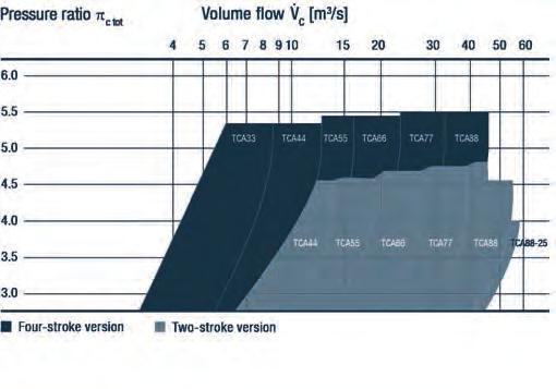

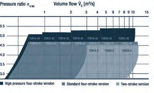

217 MAN Turbochargers and Exhaust Gas Systems TCA application range TCR application range 217

218 MAN TCA Series Technical data Turbine type Axial flow turbine Max. permissible temp. 500 C two-stroke / 650 C four-stroke Pressure ratio up to 5.5 Suitable for HFO, MDO, gas Turbocharger programme Max. supercharged engine output kw Max. permissible Type Two-stroke Four-stroke Speed Mass le* = 8.0 kg/kwh le* = 6.5 kg/kwh rpm kg TCA33-5,400 27,800 1,370 TCA44 7,000 7,900 22,500 1,950 TCA55 9,600 10,400 20,000 3,200 TCA66 13,700 14,800 16,900 5,300 TCA77 19,400 21,000 14,200 8,330 TCA88 30,000 30,000 12,000 14,000 * Specific air consumption Project Guide 218

219 Technical data Turbine type Radial flow turbine Max. permissible temp. 650 C Pressure ratio up to 5.4 Suitable for HFO, MDO, gas MAN TCR Series Turbocharger programme Max. supercharged engine output kw Max. permissible Type Two-stroke Four-stroke Speed Mass le* = 7.0 kg/kwh le* = 6.5 kg/kwh rpm kg TCR , TCR , TCR14-1,300 58, TCR16-1,850 48, TCR18 2,700 2,750 40, TCR20 4,000 4,000 33, TCR22 7,000 6,850 25,600 1,050 * Specific air consumption Project Guide 219
220 220


221 Technical data Turbine type Radial flow turbine Max. permissible temp. 650 C (opt. 720 C) Pressure ratio up to 4.5 Suitable for HFO, MDO, gas MAN NR/S Series Turbocharger programme Max. supercharged Max. permissible Mass Type engine output kw speed rpm kg NR12/S , NR14/S , NR17/S 1,350 52, NR20/S 1,870 44, NR24/S 2,690 37, NR29/S 3,820 31, NR34/S 5,400 26,300 1,450 Specific air consumption Ie = 7 kg/kwh Project Guide 221

222 MAN ECOCHARGE MAN ECOCHARGE two-stage turbocharging is suitable for high and mediumspeed engines of all fuel types and for application in all engine power ranges. Extremely high efficiencies and pressure ratios enable increased power density and improved key engine parameters. For example, it is possible to use a smaller engine for the same required power output or to achieve lower NO X emissions and lower specific fuel oil consumptions (SFOC). As a compact two-stage unit, the MAN ECOCHARGE delivers outstanding turbocharging efficiency. A variety of product types and sizes are available, ensuring the perfect turbocharger-to-engine-fit. MAN ECOCHARGE always consists of a clever combination of high and low-pressure turbochargers. While MAN TCX has been specifically designed for high-pressure applications, MAN TCA and MAN TCR round up the package as low-pressure turbochargers. 222

223 Technical data Turbine type Mixed flow turbine Max. permissible temp. 650 C Pressure ratio (two stages) up to 10.5 Suitable for HFO, MDO, gas MAN TCX Series TCX turbocharger programme Max. engine output* Max. permissible speed Type kw rpm Mass kg TCX17 8,500 40, TCX19 11,900 34, TCX21 16,900 29,000 1,325 TCX23 23,900 24,390 2,230 * le = 6 kg/kwh; phpcin = 3 bar; THPCin = 45 C Project Guide 223

224 MAN ETB The EGR blower MAN ETB is suitable for exhaust gas recirculation (EGR) engines of all fuel types in all application ranges. Specifically designed for EGR systems, the MAN ETB s active control plays an important role in enabling these systems to reach IMO Tier III emission standards. The required EGR operating conditions are achieved by using a high-speed electric motor directly coupled to the compressor wheel and controlled by a frequency converter. The MAN ETB features a highly efficient blower wheel, optimised for lowpressure ratios. The materials used are designed to withstand corrosive agents. High blower availability and variable speed operation ensure IMO Tier III compliance in emission controlled areas (ECAs). 224

225 225
 < 3.")
 (t/h) 1 1,900 3,500 4,500 28 2 2,300 3,800 4,800")


226 MAN SCR-HP L D Product Range Cluster Reactor Diameter (D) < 0.1% Sulphur Reactor Length (L) < 3.5% Sulphur Reactor Length (L) Exhaust massflow - (mm) (mm) (mm) (t/h) 1 1,900 3,500 4, ,300 3,800 4, ,800 4,000 5, ,100 4,200 5, ,800 4,800 5, ,500 5,400 6, Preliminary clustering on exhaust mass flow basis. Final clustering depends on specific engine data, which must be confirmed by MAN Diesel & Turbo. 226 Scope of supply of MAN SCR-HP is illustrated. Piping and connection of SCR to the engine to be done by shipyard.

227 MAN SCR-HP The MAN SCR-HP is a small and compact NO X emission reduction system. The compact design allows for easy integration, and the few frame sizes will cover the entire two-stroke portfolio up to 25 MW per SCR reactor. The integrated mixing unit reduces the overall length and volume. The specific honeycombs ensure a compact design. The MAN SCR-HP can be mounted in all positions and is capable of running on all fuels. Auxiliary components like the urea injection lance, urea dosing unit and urea pump module are from MAN s well-proven SCR-LP system. SCR-HP system Please note that MAN SCR-HP has passed the two-stroke provisional approval test on testbed and will after successful service test obtain full approval. Accordingly, MAN SCR-HP is ready for service test and appliance. 227

228 228

229 MAN PrimeServ
230 Service with Passion MAN Diesel & Turbo is offering a strong after sales service with a clear performance commitment, qualified and reliable experts and tailor-made solutions all combined in our global service brand MAN PrimeServ. Our approach is simple, yet effective: Premium service performed with passion meeting every customer s needs. We take the best people, qualify them professionally, listen to our customers, and provide optimum flexibility and reliability in the services we offer. We provide our customers with outstanding services, we apply the three MAN PrimeServ key-concepts in everything we do: Customer Proximity, Solution Orientation and Technical Competence. Customer Proximity MAN PrimeServ provides excellent global support through a worldwide network of service facilities. Our local presence ensures the best possible customer proximity. Our aim is to consistently meet and exceed your expectations. Whenever you require spares, technical expertise or qualified repair assistance, feel free to contact your nearest MAN PrimeServ partner. Solution Orientation For more than one hundred years, MAN PrimeServ has been a reliable partner for service solutions. We offer tailor-made service and first class technical support for every customer 365 days a year, 24 hours per day. Your requirements are the benchmark for our activities. Furthermore, we are committed to qualify our customers in the best way possible, so that the equipment and installations we supply can be operated and maintained in the most efficient and safest way. Technical Competence Our global network consists of highly-skilled experts using state-of-the-art technology. Performance according to the highest safety and quality standards has caused our technology-leadership as OEM. Our unique efficiency in service and technical competence shows that we know how to keep our products reliable and productive. 230 Environment Environmental protection plays a crucial role to us as it does for our customers. Our engineers develop technologies to reduce emissions and are working on new ways to increase the efficiency of your installations. MAN PrimeServ provides integral solutions to encounter and embrace complex regulations. We sharply focus on fulfilling all emission standards. Integration comes into play when existing engines need to be retrofitted to modern and clean dual fuel engines.
231 MAN Diesel & Turbo provides dual-fuel retrofit solutions based on the latest state-of-the-art technology. Our Heritage Brands MAN PrimeServ is our brand label for high quality after sales support for the complete product portfolio of MAN Diesel & Turbo. Through refinements to our products and repair techniques, we ensure and build on our technological leadership and technical expertise as an original equipment manufacturer (OEM) for the brands united under MAN Diesel & Turbo. Our aim is to consistently meet and exceed your expectations with innovative solutions tailored to your needs. We are the OEM for all MAN Diesel & Turbo brands and heritage brands such as: Burmeister & Wain (B&W) Mirrlees Paxman Ruston Pielstick Alpha Diesel Holeby GenSets HOMEPAGE LOCATION FINDER 231

232 232

233 Contacts
Marine Engine. IMO Tier ll and Tier lll Programme 2nd edition 2016
 Marine Engine IMO Tier ll and Tier lll Programme 2nd edition 2016 All data provided in this document is non-binding. This data serves informational purposes only and is especially not guaranteed in any
MAN B&W Marine Engines MAN Holeby GenSets. IMO Tier ll 2012
 MAN B&W Marine Engines MAN Holeby GenSets IMO Tier ll 2012 All data provided in this document is non-binding. This data serves informational purposes only and is especially not guaranteed in any way. Depending
MAN B&W ME-GI. Dual fuel low speed engine
 Dual fuel low speed engine The ME-GI Engine Supreme fuel flexibility The technology used in the design of the new two-stroke ME-GI engine combines MAN Diesel & Turbo s ME-C design with the GI-design from
L58/64, L48/60, V48/ L40/54, L32/40, V32/ L28/32A, V28/32A, L27/ L23/30A, V23/30A, 48 L32/40DG, V32/40DG 49-50
 Contents Two-stroke Propulsion Engines 4-35 K98MC, K98MC-C, 11-12 S90MC-C, L90MC-C, K90MC, K90MC-C, 13-16 S80MC-C, S80MC, L80MC, K80MC-C, 17-20 S70MC-C, S70MC, L70MC 21-23 S60MC-C, S60MC, L60MC, 24-26
MAN Diesel & Turbo a member of the MAN Group
 All data provided in this document is non-binding. This data serves informational purposes only and is especially not guaranteed in any way. Depending on the subsequent specific individual projects, the
KAWASAKI Environment-friendly New engine technology
 Norway-Japan Maritime Green Innovation Seminar 4th June, 2015 KAWASAKI Environment-friendly New engine technology 0 Yosuke NONAKA Diesel Engine Dep t. Machinery Div. Kawasaki Heavy Industries, Ltd. F4C-04-0035
Market Update Note. EcoEGR coming to your Tier III engine soon MUN
 MUN2018-02-07 EcoEGR coming to your Tier III engine soon MAN B&W two-stroke diesel engines use selective catalytic reduction (SCR) or exhaust gas recirculation (EGR) to comply with IMO Tier III requirements.
Propulsion of 30,000 dwt. Handysize Bulk Carrier
 Propulsion of 3, dwt Handysize Bulk Carrier Content Introduction...5 EEDI and Major Ship and Main Engine Parameters...6 Energy Efficiency Design Index (EEDI)...6 Major propeller and engine parameters...7
Propulsion of 46,000-50,000 dwt. Handymax Tanker
 Propulsion of 46,-, dwt Handymax Tanker Content Introduction... EEDI and Major Ship and Main Engine Parameters...6 Energy Efficiency Design Index (EEDI)...6 Major propeller and engine parameters...7 46,-,
Propulsion of 2,200-2,800 teu. Container Vessel
 Propulsion of 2,2-2,8 teu Container Vessel Content Introduction...5 EEDI and Major Ship and Main Engine Parameters...6 Energy Efficiency Design Index (EEDI)...6 Major propeller and engine parameters...7
MDT TIER III options with low sulphur fuels
 Greener Shipping Summit Athens, Greece, 10.11. 2015 MDT TIER III options with low sulphur fuels Michael Jeppesen Promotion Manager Sales & Customer Support Marine Low Speed < 1 > Agenda Greener Shipping
Propulsion of VLCC Introduction
 Propulsion of VLCC Content Introduction...5 EEDI and Major Ship and Main Engine Parameters...6 Energy efficiency design index (EEDI)...6 Minimum propulsion power...6 Major propeller and engine parameters...7,
SFOC Optimisation with Low Load or Part Load Exhaust Gas Bypass (LL-EGB, PL-EGB)
") MAN Diesel & Turbo Market Update Note 21 February 2014 SFOC Optimisation with Low Load or Part Load Exhaust Gas Bypass (LL-EGB, PL-EGB) All ME-C/ME-B engines with high-efficiency turbocharger and LL-EGB
MAN Diesel & Turbo Market Update Note 21 February 2014 SFOC Optimisation with Low Load or Part Load Exhaust Gas Bypass (LL-EGB, PL-EGB) All ME-C/ME-B engines with high-efficiency turbocharger and LL-EGB
LPG. Future-proof with ME-LGIP Dual fuel done right, again. Thomas S. Hansen Promotion & Customer Support 2rd October 2018
 Glimpse the future LPG Future-proof with ME-LGIP Dual fuel done right, again Thomas S. Hansen Promotion & Customer Support 2rd October 2018 The new MAN B&W ME-LGIP engine First ME-LGIP order EXMAR, Belgian
ME-GI Engine Fuelled by LNG
 ME-GI Engine Fuelled by LNG Andrzej Krupa Managing Director MAN Diesel & Turbo Poland Sp. z o.o. < 1 > Disclaimer All data provided on the following slides is for information purposes only, explicitly
11,000 teu container vessel
 11,000 teu container vessel An ME-GI powered vessel fitted with fuel gas supply system and boil-off gas handling 2 MAN Energy Solutions 11,000 teu container vessel Future in the making 3 Contents Main
Fuels Sulphur Cap. Vice President, Marine Sales Americas Daniel Vengel Jensen SEAM Les Gingell. 29 th of June 2018
 Fuels 2020 Sulphur Cap Daniel Vengel Jensen SEAM Les Gingell 29 th of June 2018 Vice President, Marine Sales Americas Les.gingell@man-es.com Marine Emission Regulation We are here Fuel Sulphur Content
MAN B&W S90ME-C10.5-GI-TII
 MAN B&W S90ME-C10.5-GI-TII Project Guide Electronically Controlled Dual Fuel Two-stroke Engines This Project Guide is intended to provide the information necessary for the layout of a marine propulsion
Engine Selection Guide Two-stroke MC/MC-C Engines
 Two-stroke MC/MC-C Engines This book describes the general technical features of the MC Programme This is intended as a 'tool' for assistance in the initial stages of a project. As differences may appear
MAN B&W S60ME-C8.5-GI Project Guide
 MAN B&W S60ME-C8.5-GI Project Guide Introduction Contents MAN B&W S60ME-C8.5-GI-TII Project Guide Electronically Controlled Dual Fuel Two-stroke Engines This Project Guide is intended to provide the information
ME-GI/ME-LGI Applications and references
 Japanese Yard s Seminar Copenhagen September, 2016 ME-GI/ME-LGI Applications and references René Sejer Laursen Promotion Manager, ME-GI E-mail: ReneS.Laursen@man.eu < 1 > Dual fuel concepts ME-GI vs. ME-LGI
2-strokeTechnical & Market Seminar
 MAN Diesel & Turbo - 2-st Technical & Market Seminar University of Piraeus, 25.11.2015 2-strokeTechnical & Market Seminar New Engine Programme and Developments George Drossos Head of Marine New Sales &
Asian Marine Engineering Conference 2015 MAN Diesel & Turbo SE Turbocharger. Malte Oltmanns Promotion Manager October 2015
 Asian Marine Engineering Conference 2015 MAN Diesel & Turbo SE Turbocharger Malte Oltmanns Promotion Manager October 2015 MAN Diesel & Turbo Malte Oltmanns Asian Marine Engineering Conference 2015 / MDT
MAN B&W Dual Fuel Engines
 MAN B&W Dual Fuel Engines Athens Seminar on 2 th Oct. 2018 Thomas S. Hansen Two-Stroke Promotion & Customer Support 2 th Oct. 2018 Today - The Dual Fuel success 4 x World s first duel fuel driven ships
The ME-LGIP Engine fueled by LPG
 The ME-LGIP Engine fueled by LPG Niels B. Clausen Senior Manager EELEE/Engine and System Application Marine Two-Stroke, Engineering < 1 > Towards Greener Future Portfolio of solutions Countermeasures for
MAN B&W G80ME-C9.2-TII Extended Layout Area Project Guide
 MAN B&W G80ME-C9.2-TII Extended Layout Area Project Guide Electronically Controlled Two stroke Engines This Project Guide is intended to provide the information necessary for the layout of a marine propulsion
MAN B&W G70ME-C9.2-TII
 MAN B&W G70ME-C9.2-TII Project Guide Electronically Controlled Two stroke Engines This Project Guide is intended to provide the information necessary for the layout of a marine propulsion plant. The information
MAN B&W G60ME-C9.5 Project Guide
 MAN B&W G60ME-C9.5 Project Guide Introduction Contents MAN B&W G60ME-C9.5-TII Project Guide Electronically Controlled Two stroke Engines This Project Guide is intended to provide the information necessary
MAIN DATA: L35MC6 TierII, S35MC7 TierII, Specific Cylinder Oil Consumption TierII
 MAIN DATA: L35MC6 TierII, S35MC7 TierII, Specific Cylinder Oil Consumption TierII L35MC6 TierII Bore:350mm Stroke:1050mm Layout Layout points L1 L2 L3 L4 speed min -1 210 210 178 178 mep MPa 1.84 1.47
MAN B&W L70ME-C8.2-TII
 MAN B&W L70ME-C8.2-TII Project Guide Electronically Controlled Two-stroke Engines This Project Guide is intended to provide the information necessary for the layout of a marine propulsion plant. The information
MAN 18V48/60TS. Two-stage turbocharged diesel engine
 MAN 18V48/60TS Two-stage turbocharged diesel engine MAN Diesel & Turbo Powering the world responsibly MAN Diesel & Turbo is the world s leading provider of large-bore diesel engines and turbomachinery.
MAN B&W S70ME-C8.5-TII
 MAN B&W S70ME-C8.5-TII Project Guide Electronically Controlled Two stroke Engines This Project Guide is intended to provide the information necessary for the layout of a marine propulsion plant. The information
Upgrade on Environmentally-friendly Mitsui MAN-B&W Engine
 Environmental Technology Seminar 11.04.2014 環境に優しい三井 MAN-B&W エンジン開発の最新状況 Upgrade on Environmentally-friendly Mitsui MAN-B&W Engine Mitsui Engineering & Shipbuilding Co., Ltd Diesel Design Department Ichiro
MAN B&W G50ME-B9.3-TII
 MAN B&W G50ME-B9.3-TII Project Guide Electronically Controlled Two-stroke Engines with Camshaft Controlled Exhaust Valves This Project Guide is intended to provide the information necessary for the layout
MAN Diesel & Turbo. Main Engine Room Data. Project name BrasNave 25 Project type Project number 3 Date 2010 Yard
 MAN Diesel & Turbo Main Engine Room Data Main Engine Compliance 6S80MC6.1-TI IMO-NOx Tier I Project name BrasNave 25 Project type Project number 3 Date 2010 Yard Country Brasil Made by BrasNave Department
MAN B&W S50ME-B8.3-TII
 MAN B&W S50ME-B8.3-TII Project Guide Electronically Controlled Two-stroke Engines with Camshaft Controlled Exhaust Valves This Project Guide is intended to provide the information necessary for the layout
MAN B&W G60ME-C9.5-TII
 MAN B&W G60ME-C9.5-TII Project Guide Electronically Controlled Two-stroke Engines This Project Guide is intended to provide the information necessary for the layout of a marine propulsion plant. The information
MAN Diesel & Turbo. Market Update Note 15 March G95ME-C9.2 and S90ME-C10.2
 MAN Diesel & Turbo Market Update Note 15 March 2013 G95ME-C9.2 and S90ME-C10.2 As a consequence of the market development towards further optimisation of the propulsion efficiency of large modern container
MAN B&W S90ME-C9.2-GI IMO Tier II Project Guide
 MAN B&W S90ME-C9.2-GI IMO Tier II Project Guide Introduction Contents MAN B&W S90ME-C9.2-GI-TII Project Guide Electronically Controlled Dual Fuel Two-stroke Engines This Project Guide is intended to provide
MAN B&W S46ME-B8.3 IMO Tier II Project Guide
 MAN B&W S46ME-B8.3 IMO Tier II Project Guide Introduction Contents MAN B&W S46ME-B8.3-TII Project Guide Electronically Controlled Two-stroke Engines with Camshaft Controlled Exhaust Valves This Project
MAN B&W S90ME-C9.2-GI-TII
 MAN B&W S90ME-C9.2-GI-TII Project Guide Electronically Controlled Dual Fuel Two-stroke Engines This Project Guide is intended to provide the information necessary for the layout of a marine propulsion
MAN B&W S50ME-C8.5 Project Guide
 MAN B&W S50ME-C8.5 Project Guide Introduction Contents MAN B&W S50ME-C8.5-TII Project Guide Electronically Controlled Two stroke Engines This Project Guide is intended to provide the information necessary
MAN B&W G45ME-C9.5 Project Guide
 MAN B&W G45ME-C9.5 Project Guide Introduction Contents MAN B&W G45ME-C9.5-TII Project Guide Electronically Controlled Two stroke Engines This Project Guide is intended to provide the information necessary
Tier III considerations
 Tier III considerations IMO Tier III Regulations NECA IMO Tier III Regulation for NOx From 2016 in the North American Emission Control Areas or the US Caribbean Sea Emission Control Areas It is a fact!
MAN B&W K98ME7.1 IMO Tier II Project Guide
 MAN B&W K98ME7.1 IMO Tier II Project Guide Introduction Contents MAN B&W K98ME7.1-TII Project Guide Electronically Controlled Two-stroke Engines This Project Guide is intended to provide the information
MAN B&W G95ME-C9.2-TII
 MAN B&W G95ME-C9.2-TII Project Guide Electronically Controlled Two-stroke Engines This Project Guide is intended to provide the information necessary for the layout of a marine propulsion plant. The information
MAN B&W S50ME-B9.5 IMO Tier II Project Guide
 MAN B&W S50ME-B9.5 IMO Tier II Project Guide Introduction Contents MAN B&W S50ME-B9.5-TII Project Guide Electronically Controlled Two-stroke Engines with Camshaft Controlled Exhaust Valves This Project
MAN B&W S65ME-C8.2-GI IMO Tier II Project Guide
 MAN B&W S65ME-C8.2-GI IMO Tier II Project Guide Introduction Contents MAN B&W S65ME-C8.2-GI-TII Project Guide Electronically Controlled Dual Fuel Two-stroke Engines This Project Guide is intended to provide
MAN B&W S80ME-C8.2-GI IMO Tier II Project Guide
 MAN B&W S80ME-C8.2-GI IMO Tier II Project Guide Introduction Contents MAN B&W S80ME-C8.2-GI-TII Project Guide Electronically Controlled Dual Fuel Two-stroke Engines This Project Guide is intended to provide
Internationaler Congress für Schiffstechnik
 Internationaler Congress für Schiffstechnik Technologien zur Reduzierung der Betriebskosten bei Einhaltung aktueller und zukünftiger Emissionen, Peter Balle, Hamburg, 10.09.2015 CourtesyMAN of Nordic Diesel
MAN B&W S50ME-C8.2-GI IMO Tier II Project Guide
 MAN B&W S50ME-C8.2-GI IMO Tier II Project Guide Introduction Contents MAN B&W S50ME-C8.2-GI-TII Project Guide Electronically Controlled Dual Fuel Two-stroke Engines This Project Guide is intended to provide
Insight in the Development of MAN s Game Changing 45/60CR Engine Portfolio
 Insight in the Development of MAN s Game Changing 45/60CR Engine Portfolio Alexander Knafl, PhD Head of Advanced Engineering & Exhaust Aftertreatment MAN Diesel & Turbo, Germany < 1 > Disclaimer All data
ECO optimization with NOx equipment
 Greener Shipping Summit Athens Greece, 14 th November 2017 ECO optimization with NOx equipment Michael Jeppesen Promotion Manager Promotion & Sales, Two Stroke < 1 > Agenda 1 Influencers of emission compliance
MAN B&W G60ME-C9.5-TII
 MAN B&W G60ME-C9.5-TII Project Guide Electronically Controlled Two-stroke Engines This Project Guide is intended to provide the information necessary for the layout of a marine propulsion plant. The information
SOx scrubbers Engine Makers view MDT points, markets and Tier III combinations. Greener Shipping Summit Jesper Arvidsson
 SOx scrubbers Engine Makers view MDT points, markets and Tier III combinations Greener Shipping Summit 2017 Athens, Greece 2017-11-14 Jesper Arvidsson Engineering/Operation/ Emission Reduction Technology
MAN B&W S50ME-C8.2 IMO Tier II Project Guide
 MAN B&W S50ME-C8.2 IMO Tier II Project Guide Introduction Contents MAN B&W S50ME-C8.2-TII Project Guide Electronically Controlled Two-stroke Engines This Project Guide is intended to provide the information
America s Tropical Shipping Orders Complete MAN Diesel & Turbo Packages
 America s Tropical Shipping Orders Complete MAN Diesel & Turbo Packages Copenhagen, 13/02/2017 Tropical Shipping, the largest provider of reliable logistics solutions to the Bahamas and Caribbean, has
Engine Selection Guide
 MAN B&W 98-50 ME/ME-C-TII Type Engines Engine Selection Guide Electronically Controlled Two stroke Engines This book describes the general technical features of the ME Programme. This Engine Selection
Engine Selection Guide
 MAN B&W 70-60 ME-GI/-C-GI-TII Type Engines Engine Selection Guide Electronically Controlled Two stroke Engines This book describes the general technical features of the ME/-GI Programme. This Engine Selection
Low Container Ship. Speed Facilitated by Versatile ME/ME-C Engines
 Low Container Ship Speed Facilitated by Versatile ME/ME-C Engines Contents Introduction...5 ME/ME-C Engines...6 Part Load Optimisation, ME/ME-C Engines...7 Low Load Mode...8 Low Load Operation with MC/MC-C
MAN B&W G90ME-C10.5. IMO Tier ll Project Guide
 G90ME-C10.5 Introduction Contents G90ME-C10.5-TII Electronically Controlled Two-stroke Engines This is intended to provide the information necessary for the layout of a marine propulsion plant. The information
TrainMos II. Madrid-November LNG and New Fuels for the Maritime Industry. Is the Technology Ready?
 MAN DIESEL & TURBO TrainMos II. Madrid-November-2.015 LNG and New Fuels for the Maritime Industry. Is the Technology Ready? Fernando Marcos +34 670 416 409 Fernando.Marcos@man.eu < 1 > Disclaimer All data
MAN B&W Two-Stroke Service Experience Imabari & Tokyo - November 2014
 MAN B&W Two-Stroke Service Experience Imabari & Tokyo - November 2014 Stig Baungaard Jakobsen Senior Manager Operation Engineering < 1 > Agenda 1 Staybolt Failures on S90ME-C9 2 Starting Issue for S90ME-C8&9
The MAN B&W Brand. Low Speed Engines
 The MAN B&W Brand Low Speed Engines Atrium of MAN Diesel & Turbo's Copenhagen headquarters MAN B&W The legendary brand With industrial roots that reach all the way back to the 18th century, MAN Diesel
MAN B&W K90ME9-TII. Project Guide. Electronically Controlled Two stroke Engines
 MAN B&W K90ME9-TII Project Guide Electronically Controlled Two stroke Engines This Project Guide is intended to provide the information necessary for the layout of a marine propulsion plant. The information
MHI-MME WHRS - STG. Environment friendly and economical solution MITSUBISHI HEAVY INDUSTRIES, LTD. All Rights Reserved.
 MHI-MME WHRS - STG Environment friendly and economical solution 2017.01.24 2016 MITSUBISHI HEAVY INDUSTRIES MARINE MACHINERY & ENGINE CO., LTD. All Rights Reserved. 1 Contents Overview 1. Outline, WHRS-STG
Engine Selection Guide
 MAN B&W 98-50 MC/MCC-TII Type Engines Engine Selection Guide Camshaft Controlled Twostroke Engines This Project Guide is intended to provide the information necessary for the layout of a marine propulsion
MAN B&W S46ME-B8-TII
 MAN B&W S46ME-B8-TII Project Guide Electronically Controlled Two stroke Engines with Camshaft Controlled Exhaust Valves This Project Guide is intended to provide the information necessary for the layout
A robust gas combustion solution
 CIMAC Cascades October 2014 ME-GI dual fuel done right The 2 stroke Dual Fuel ME-GI Engine A robust gas combustion solution Rene Sejer Laursen E mail: ReneS.Laursen@man.eu ❶❷❸❹ < 1 > The Licensees Reported
Technical Update December 2016, Athens, Greece TIER III is now!
 Technical Update December 2016, Athens, Greece TIER III is now! Michael Jeppesen Promotion Manager, Customer Support Two Stroke Marine MAN Diesel & Turbo < 1 > Agenda 1 Tier III uncertainty, motivation,
An engine manufacturers view on. LNG as fuel
 An engine manufacturers view on LNG as fuel Challenge and potential of LNG as engine fuel, Michael Werner, test engineer Dual Fuel engines, Workshop Metrology for LNG, Copenhagen, 2015-05-19 Disclaimer
MAN B&W two stroke engines in China. MAN Diesel & Turbo The road to 100 % Local Production in China of Environmental Friendly Engines
 MAN B&W two stroke engines in China The road to 100 % Local Production in China of Environmental Friendly Engines < 1 > New ME-C Mk. 10 Design Platform Top Controlled Exhaust Valve/ Fuel Booster Injection
Extent of Delivery. Extent of Delivery / Order Specifications W-XDF Engines. Instructions. All quantities to be stated for one vessel
 Extent of Delivery Instructions All quantities to be stated for one vessel or Included in extent of delivery The purpose of the Extent of Delivery (EOD) is to provide a guideline for the technical specification
Global Greenship, September 2009 Low Sulfur Fuel and Emissions Advances
 Global Greenship, September 2009 Low Sulfur Fuel and Emissions Advances ECA and SECA Trends Top Container Ports : 1. Singapore 2. China, Shanghai 3. China, Hong Kong 4. China, Shenzhen 5. South Korea,
MAN Diesel & Turbo s Solutions for LNG Fuelled Vessels. Christodoulopoulos Dionissis Managing Director Poseidon Med, 8/12/16 Piraeus
 MAN Diesel & Turbo s Solutions for LNG Fuelled Vessels Christodoulopoulos Dionissis Managing Director Poseidon Med, 8/12/16 Piraeus < 1 > Agenda 1 Evironmental Regulations 2 Product Portfolio 3 References,
MAN 51/60DF. Dual-fuel flexibility and reliability
 MAN 51/60DF Dual-fuel flexibility and reliability MAN Diesel & Turbo Powering the world responsibly MAN Diesel & Turbo is the world s leading provider of large-bore diesel engines and turbomachinery.
MAN Technical Symposium 2016 MAN Turbochargers Ready for tomorrow
 MAN Technical Symposium 2016 MAN Turbochargers Ready for tomorrow Sephardim Koblenz < 1 > MAN Turbochargers Product Portfolio More than 250 Millions of operating hours TCA Almost 7500 deliveries TCR Almost
Improved Efficiency and Reduced CO 2
 Improved Efficiency and Reduced CO 2 Content Introduction...5 Major Propeller and Main Engine Parameters...5 Propeller...6 Main engine...6 Ship with reduced design ship speed...6 Case Study 1...6 75,000
MAN B&W S80MC-C8-TII
 MAN B&W S80MC-C8-TII Project Guide Camshaft Controlled Twostroke Engines This Project Guide is intended to provide the information necessary for the layout of a marine propulsion plant. The information
News & Updates on MAN Dual Fuel Engines. Colin Peesel Sales Manager Engine & Marine Systems Inspectors Day Bremen,
 News & Updates on MAN Dual Fuel Engines Colin Peesel Sales Manager Engine & Marine Systems Inspectors Day Bremen, 06.06.2018 MAN Diesel & Turbo [optional: Brand] Author Current topic 00.00.2012 < 1 > Agenda
Gas Fuelled Container Ship
 SAMSUNG HEAVY INDUSTRIES Company name Gas Fuelled Container Ship ( Evaluation of Economic Analysis ) H.C. Jung October 16, 2015 1 Contents Background - Environmental Issue - IMO Future Regulation Gas Fuelled
At the Forefront of Green Engine Technology. The MAN B&W ME-GI and ME-LGI dual fuel concepts
 At the Forefront of Green Engine Technology The MAN B&W ME-GI and ME-LGI dual fuel concepts Contents Introduction...5 A quick tour of the technological differences between the GI and LGI concept...5 The
Effect of SOx and NOx Regulation Implementation, ECA s and NOx Tier III Current Developments in General
 Effect of SOx and NOx Regulation Implementation, ECA s and NOx Tier III Current Developments in General ASEF 2013, KOBE, November 6, 2013 Toru Nakao Hitachi Zosen Corporation, Japan 2 ECA status Emission
World Record Dual-Fuel Engines Ordered by Leading American Shipping Company
 World Record Dual-Fuel Engines Ordered by Leading American Shipping Company Copenhagen, 11/11/2013 LNG-capable ME-GI units to power newbuilding container ships Matson Navigation Company, Inc. a subsidiary
MAN B&W S50MC-C8-TII
 MAN B&W S50MC-C8-TII Project Guide Camshaft Controlled Twostroke Engines This Project Guide is intended to provide the information necessary for the layout of a marine propulsion plant. The information
Copyright by WÄRTSILÄ FINLAND Oy
 Copyright by WÄRTSILÄ FINLAND Oy All rights reserved. No part of this booklet may be reproduced or copied in any form or by any means (electronic, mechanical, graphic, photocopying, recording, taping or
Mitsubishi UE Engine Updates. New UEC LSH-Eco Series and Service Results
 Messrs. *** Mitsubishi User s Seminar in Athens Mitsubishi UE Engine Updates CONFIDENTIA L New UEC LSH-Eco Series and Service Results 16th June 2016 Masahiko Okabe Contents 1. Overview of Mitsubishi UE
MAN B&W S40MC-C9.2 IMO Tier II Project Guide
 MAN B&W S40MC-C9.2 IMO Tier II Project Guide Introduction Contents MAN B&W S40MC-C9.2-TII Project Guide Camshaft Controlled Two-stroke Engines This Project Guide is intended to provide the information
MAN B&W S70MC-C8.2 IMO Tier II Project Guide
 MAN B&W S70MC-C8.2 IMO Tier II Project Guide Introduction Contents MAN B&W S70MC-C8.2-TII Project Guide Camshaft Controlled Two-stroke Engines This Project Guide is intended to provide the information
The ME-LGIM engines For the use of methanol as fuel
 International Methanol Conference May 2017 at DTI. Kjeld Aabo Director Customer support MAN Diesel & Turbo Copenhagen, Denmark The ME-LGIM engines For the use of methanol as fuel < 1 > Design and Manufacturing
Essential Wear Parts. MAN PrimeServ
 MAN PrimeServ 2 Introduction Certain spare parts for the two-stroke engine are considered to be Essential Wear Parts as they are key components that have a critical effect on the performance of the engine.
Competitive Edge through Environmental Performance
 Competitive Edge through Environmental Performance Bo Cerup-Simonsen, Vice President Ph.D. Naval Architect, MBA Shipping & Logistics Blue Event no. 23 - Copenhagen, 3rd February 2011 (MMT) is a highly
Extent of Delivery. Extent of Delivery / Order Specifications W-XDF Engines. Instructions. All quantities to be stated for one vessel
 Extent of Delivery Instructions All quantities to be stated for one vessel or Included in extent of delivery The purpose of the Extent of Delivery (EOD) is to provide a guideline for the technical specification
Calculation of specific fuel oil consumption (SFOC)
") Calculation of specific fuel oil consumption (SFOC) General Figure describes the standardized calculation order for conversion of SFOC from Reference condition (ISO) to Site/FAT condition, and from Site/FAT
Calculation of specific fuel oil consumption (SFOC) General Figure describes the standardized calculation order for conversion of SFOC from Reference condition (ISO) to Site/FAT condition, and from Site/FAT
NOx Reduction Technologies for 2-stroke Diesel Engines to Meet IMO Tier III
 NOx Reduction Technologies for 2-stroke Diesel Engines to Meet IMO Tier III 6 th Asian Shipbuilding Expert s Forum, Guangzhou, November 22, 2012 Takahiro Fujibayashi Hitachi Zosen Corporation, Japan Topics
MAN Diesel's First VTA Application Achieves 10,000 Operating Hours
 MAN Diesel's First VTA Application Achieves 10,000 Operating Hours 05/ In 2007, MAN Diesel s Business Unit Turbocharger, based in Augsburg, Germany, equipped the first engine in a commercial application
Pacific Ports Air Quality Collaborative Conference Dec
 Pacific Ports Air Quality Collaborative Conference Dec. 2006. How engine manufacturers are meeting the challenge by refining their technologies within Exhaust gas emission Kjeld Aabo Director Customer
CIMAC Position Paper
 06 2015 CIMAC Position Paper New 0.10% sulphur marine (ECA) fuels Introduced to the market to meet the SO x ECA fuel sulphur specification of maximum 0.10% By CIMAC WG7 Fuels This publication is only for
Extent of Delivery. W-X35-B/40-B Engines. Extent of Delivery / Order Specifications. Instructions. All quantities to be stated for one vessel
 Extent of Delivery Instructions All quantities to be stated for one vessel or Included in extent of delivery The purpose of the Extent of Delivery (EOD) is to provide a guideline for the technical specification
Slow Steaming. Benefiting retrofit solutions from MAN PrimeServ
 Slow Steaming Benefiting retrofit solutions from MAN PrimeServ 2 Slow Steaming Slow Steaming Introduction Out of the total operational costs of a ship, fuel costs account for by far the highest proportion.