Linear guide systems. Linear and Motion Solutions NL 1002 E
|
|
|
- Amelia Hawkins
- 5 years ago
- Views:
Transcription


1 inear guide systems inear and Motion Solutions N 1002 E
2

3 inear guide systems
4 Summary Heavy-ine Rolbloc V-ine Guide rails GU..M, GU..MT Guide Rollers RKU Guide Wheels FKU Floating Guide Rollers RKU ubricator UU Guide pins SAG Guide rails GP..MC Ground guide rails GP..M Guide Rollers PK Guide Wheels FK Guide Rollers GC Cam followers FG (needle) and FGU (roller) ubricator UP Guide rails GU..M, GU..MT Carriages ROOC M Carriages ROOC Adjustment plates PR Sand blasted guide rails FS..MT Ground guide rails FS..M Sand blasted guide rails FSH..MT, FSX..MT Ground guide rails FSH..M, FSX..M Guide Rollers FR..EU Guide Rollers FR..EU AS, FR..EU AZ Guide Rollers FRN..EI Guide Rollers RKY, RKX Guide Rollers FKY, FKX Floating Guide Rollers FR..EU Floating Guide Rollers RKX, RKY Spacers FS and FSH ubricator UY - UX
5 For medium-heavy loads For medium-heavy loads Dirty environment For medium-heavy loads Dirty environment For medium-heavy loads
6 Summary Multi-Motion-ine Circular rails FSR..M Oval circuit FSRO Ring circuit FSRQ Steering carriages T4R... C-ine ase-ine Flexi-ine 645 Guide Rails S Guide Rollers RCS Guide Rollers RAS Carriages C3 RCS, C3 RAS, C3 RYS Carriages C4 RCS, C4 RAS, C4 RYS Carriages C5 RCS, C5 RAS, C5 RYS Guide rails DC Guide rails C Guide Rollers PFV Guide Rollers RKO Carriages T4PFV Wipers NAID ubricator UC Guide rails FWS Guide rails FWH Guide Rollers FR..EU Guide Rollers FR..EU AS, FR..EU AZ Floating Guide Rollers FR..EU Carriages T4FR Guide rails FWN Carriages TA4, T4
7 For all applications For light-medium loads For medium loads Aggressive environment For light-medium loads 105 For light-medium loads
8 Summary U-ine Guide rails M Guide Rollers RC, RCP, PFV Floating Guide Rollers RA Guide Wheels GA Carriages C3RC, C3RA, C3RY Carriages C4RC, C4RA, C4RY Carriages T4RC, T4RCP, T4PFV, T4RA, T4RY ubricator UM Guide rails M 20
9 For light-medium loads
10 Technical features Nadella linear systems With this line of products, NADEA confirms the aim to provide manufacturing solutions tailored to the user s needs in order to achieve simple automation at a low cost. The process under way of transferring production automation and relevant handling onto increasingly heavier and cumbersome units has prompted us to seek original and flexible components for the different commodity sectors. We have accumulated sound working experience in the following sectors: - marble-working machinery - foundry machinery - metal sheet working machinery - special lifting machines - pick up - automatic warehouses - textile machines - machine tool protections and utilities - oxygen cutting machines Our Technical Department works with Customers and recommends the best component choice by making the calculations needed to determine the best life. Guides ength The maximum length of each single guide component is shown on the dimensional tables. The standard lengths of the rails are determined by adding the product of the fixing hole centre distance and the number of holes to twice the end dimension (see dimensional tables). ength ength tolerance 150 < < < < < ± 0,5 ± 0,8 ± 1,2 ± 2 ± 2,5 Joints For strokes of greater length, the guide components can be joined after grinding the end faces (suffix R or RR). To maintain the hole centre distance tolerance, when ordering always specify the number of individual rails making one continuous length. Please specify in the order when rails have to be matched. The junctions are marked (letters and numbers) to avoid a mix-up of different rails. Fixing holes The guides are available with standard holes, as shown in dimensional tables, with special hole layout or without holes (see order code referencing) Standard tolerance for hole position is ± 0,25 mm. A The standard boring layout is designed to fit most common application requirements, but connection strength has to be evaluated on the application case. Steel guides Junction 0,5 A General Steel rails are made of bearing steel to give best stability and durability. Raceways are induction hardened to achieve 58 HRC hardness minimum. The rail core remains soft to allow easy machining. Rails can be provided with different finishes to meet specific application requirements. Guide rails MT type. Profile is produced by cold drawing process, raceways are induction hardened and sandblasted to improve surface strength and finish. Guide rails M type. Profile is usually produced by cold drawing process, induction hardened on raceways and ground to improve surface finish and profile geometry and to remove the partially decarburised surface (0.1 mm max on cold drawn rails..mt). Ground rails have to be used when there are high loads, heavy-duty cycles or when there is a high accuracy requirement. Guide rails MC type (flat rail GP..MC only). MC rails are induction-hardened on every side and finished by-arough grinding. Options Corrosion protection For use in oxidising environments or in the presence of corrosive agents, the guides are available with chemical nickel-plating protective anticorrosion treatment (suffix NW.). This treatment features substantial mechanical characteristics together with a resistance to salty mist corrosion superior to that of hard chrome. On request many rails are available in stainless-steel version (suffix NX) Circular rail On request circular rails can be provided. Circular rails can be used as an alternative to rotating devices or as junction between straight rails. Technical features Standard rail straightness (for non-mounted rails) is 0.5 mm/m max. Higher accuracy can be supplied on request. 8
11 Technical features Temperature Standard operating temperature range is 20 C up to 150 C. In lower or higher temperature applications please contact Nadella Technical Service. Special care is required if guide rollers are operating at maximum temperature. Aluminium guides General Made by joining an aluminium alloy support element and hardened steel rods that form the sliding surfaces. The best features of the two materials and relevant working technologies are combined to give the lightness of the alloy and the hardness and surface finish of the rods. Guides of this type can be used for structural functions; they have a high moment of inertia that enables them to be used in many applications as carrying structures. Aluminium extruded profiles are stabilised and anodised. Sliding rods are induction hardened and ground. Options Corrosion protection For use in oxidising environments or in the presence of corrosive agents, the guides of this series can feature stainless-steel bars (suffix NX). Chromium-plated rods Optional chromium-plated rods are available (suffix CH); the thickness of the chromium plating is 10 ± 5 μm with hardness 800 HV. Please check option availability in dimensional tables. Joints In case rail made by multiple C-DC or M rails the most efficient joint can be realized with the insertion of a dowel pin inside the rods. This solution allows for simple assembly at the site and maintains alignment under load. Technical features Standard rails straightness (for non mounted rails) is 0.5 mm/m maximum. Higher accuracy can be supplied on request. Temperature Standard operating temperature range is 20 C up to 70 C. Applications with frequent temperature variation should be avoided. For operating conditions outside the given range please contact Nadella Technical Service. Guide rollers General Nadella provide a wide range of guide rollers to be able to meet different technical and economic requirements. All guide rollers are produced in concentric and eccentric versions to allow backlash adjustment during assembly on final equipment. Eccentric rollers are identified by additional R in the code. The sides of the races of the guide roller are slightly convex. esides reducing rolling friction, this also permits offsetting slight guide flexing or small assembly alignment errors. Guide rollers are fitted with seals or shields for bearing protection and lubricant retention as described in dimensional tables. Guide rollers based on needle or tapered roller bearings (FRN..EI,RK..,PK..) are recommended for critical applications with heavy axial loads and/or shock loading. Guide rollers based on ball bearings (FR..EU, PFV, RC) are more suitable for lighter loads or high dynamic systems. The carriages based on Rolbloc s system are recommended for applications with heavy loads, high frequency of work and aggressive environment (dust, abrasive). For rails FWS the joint can be realised by protruding the rods of one rail in order to engage them in the profile of the next rail. In the final configuration there will be a small gap between the aluminium profiles (see next drawing). When mounting guide rails opposite to each other with connected carriages, as shown in the next sketch, a high level of parallelism between the guide rails is required when axially rigid rollers are used. To avoid operating problems it is recommended to use axial rigid fixed rollers on one carriage e.g. FR.. EU/FRR EU and axial movable rollers on the other 9


12 Technical features carriage e.g. FR..EU/FRR..EU Movable rollers allow a little misalignment between the opposite mounted guide rails. Accessories Tables and carriages Standard table and carriages for C-DC and M systems incorporate a black anodised aluminium plate fitted with guide rollers. Wipers Standard wipers NAID for C-DC rails are made from NR compound moulded on a steel plate. Another solution is to use one profiled guide rail e.g. FS and on the opposite side a flat rail e.g. GP in connection with rollers GC or PK. ubricators Are composed by two main parts: a plastic box with the same shape profile of the rail, and a lubricated felt; the felt is slightly pressed on the raceways by a spring. The plastic box, that drags the raceways, works as a wiper, and remove dust and shavings. F FS Technical features ubrication Guide roller FRN..EI permits bearing relubrication. All other guide rollers are long life lubricated. Temperature Guide roller should not operate at constant temperature above 80 C. For short durations 100 C can be accepted. For higher temperature please see the option section. Speed limit Max velocity has to be determined for each application relevant to the guide roller type, size and load conditions. As general value, in normal conditions maximum speed is 4 m/sec but, with the correct chose of the components, the speed can reach 10 m/s. Contact Nadella Technical service in case of specific request. Options GP The plastic box can be mounted directly on the guide rollers plate by the appropriate aluminium plate included in the kit. In the lubricators for guide rollers size 52 or higher, the grease nipple allows an easy connection with a relubrication system. For the simply lubrication of the rails you can use one lubricator only on each raceway; in order to wipe the raceways it is better to mount two lubricators, before and after the carriage. The lubricators are supplied with the felt already lubricated. Use in dirty environment Due to the design cam rollers with profile are especially adapted to the use in rough and dirty environment. This properly has proved true in many applications such as welding plants, steel and grinding machines and is superior to recirculating ball bearing guides in continuous operation. Corrosion protection For uses in oxidising environments or in the presence of corrosive agents, the guide rollers are available in stainless steel (suffix NX) the guide rollers with tapered rollers (RKU, RKY/X, FKU, FKY/X) and needles (FRN) are equipped with standard bearings. Check in the dimensional table component availability. High temperature On request guide rollers can be equipped with Viton seals to operate at temperature up to 120 (suffix V). Check in the dimensional table component availability. 10
13 Technical features ubrication earing lubrication All the guide rollers, except for the FRN..EI, based on needle bearings, are equipped with long life lubricated bearings. This means that the grease inside the bearing is enough for the entire life of the roller guide. The roller guide type FRN..EI, with needle bearings, accommodates the re-lubrication of the bearings. Rail lubrication Rails must be lubricated. This allows reducing the friction, to reach the calculated lifetime of the system and to work at high speed. No or insufficient lubrication will cause rapid deterioration. The typical signal of tribocorrosion is the presence of a red/dark oxide and rapid wearing of the rail and guide rollers. The lubrication of the rail, the working environment and the load must be considered all together for a correct estimation of the lifetime of the guide system. Generally speaking, for application with low duty frequency, a periodic relubrication with a grease or with a viscous oil will sufficiently maintain the lubrication film. The re-lubrication interval depends on the application and must always be tested in the real working conditions. In a system with ground rails and short stroke without lubricators, you can consider a relubrication interval every 100,000 cycles. Increasing the load, speed or stroke, or using an under sized bearing will increase lubrication demand and result in a shorter lubrication interval. For a constant lubrication we suggest the use of felt lubricators to ensure a constant layer of lubricant between guide rollers and raceways. Felt lubricators enlarge the lubrication interval more than ten times. so that any movement caused by vibration will cause the nut to be tightened. Ensure the preload is not increased when tightening the nut. A simple way of setting a roller preload is as follows: 1 move the slider on the guide, holding the roller being adjusted with two fingers to prevent it from rotating 2 increase the preload by means of the wrench 3 repeat step 1 making sure the roller slides without rolling 4 when it is no longer possible to prevent roller rolling, slightly decrease the preload and fully tighten the lock nut, thereby setting the position of the eccentric. When correctly adjusted it is just possible to cause the guide roller to slip on the guide rail when a torque is applied to the roller. Guides For single guide rail type FS, FWS, DC and M no special assembly instructions are necessary. For multiple parallel rails parallelism has to be checked to avoid guide rollers overload or excessive carriage play. When constant preload is required parallelism error has to be lower that mm. Connection between the rail and the mounting surface has to be designed accordingly with the operating condition to ensure proper product positioning and functionality. The direction and intensity of the load, the number and strength of the screws, the geometry of mounting surfaces, use of pins or wedges have to be evaluated to fully utilize the linear guide load capacity. The recommended lubricants are greases and oil for bearings, linear rails or chains, with a high viscosity of the basic oil and with EP additives, in order to separate the metallic surfaces even with low speed. Assembly instructions Guide rollers The eccentric guide rollers allows the preload or clearance of the carriage to be adjusted independently of the guide roller mounting hole positioning tolerance or the distance between the rails. Recommended mounting hole tolerance is H7. When adjusting the eccentric guide roller care has to be taken to avoid excessive preload. Excessive preload can reduce the life of the linear system. Set the preload turning the guide roller counterclockwise Carriages Carriages are supplied with concentric guide rollers nut tighten already. Eccentric guide rollers have to be set and tighten during final assembly operation by customer. 11
14 Technical features Calculation procedure Calculation is carried out in two steps, first defining the forces on the most heavily loaded roller and then estimating the safety factors and life. Calculating the loads on the guide rollers In the case of complex load situations, with forces acting in different directions, calculating the reactions on the rollers is difficult and hard to simplify. In the event of the applied load having a direction parallel to one of the co-ordinate axes, the radial Pr and axial Pa components of the reactions on the most loaded roller can be obtained using elementary formulas. With reference to the diagrams shown, we obtain the load components on the rollers relevant for checking and calculating the life, applying the following methods. Diagram a) load F applied parallel to axis Y a) I y Pa = Y I x F z F 2 Ic x F F ( Ix + 2 x F ) F z F tan α Pr = + 2 Ix 2 Ic F X Y z F F Z Angle α in the formulas is half the groove angle. ook in the dimensional table notes for the correct value. Distance Ic is the effective contact distance. With the exception of ROOC system the correct value is calculated as the guide rollers centre distance across the rail plus or minus the outer guide roller diameter De, depending if the guide is outside or between the rollers. Guide between the rollers Guides outside the rollers Diagram b) load F applied parallel to axis Z b) I y Y x F y F X Y Z F I x Iy Ic Ic Iy Ic = Iy - De Ic = Iy + De F F x F F y F Pa = I x 2 I c Pr = Pa tan α In case of ROOC the distance Ic is the distance between the rails basis. Diagram c) load F applied parallel to axis X Guides between the rollers Guides outside the rollers c) Y Y z 1 Ih Ih F 1 Iy Ic Ic Iy I y X y 1 y 2 Z F 2 Ic = Iy - 2 Ih Ic = Iy + 2 Ih I x z 2 12
15 Technical features In this case the external load F 1, applied at the point of co-ordinate y 1 z 1, should be considered together with reaction F 2 = -F 1, applied at the point of co-ordinate y 2 z 2. Calling Δy the absolute value of y 2 -y 1 and Δz the absolute value of z 2 -z 1, the following formula is used: Pa = F 1 Δz 2 I x Guide roller calculation In the table for each roller the following data is specified: C w basic dynamic load, it is the radial load [N] that applied to the guide roller gives 100 km nominal life*. F r limit radial load, it is the maximum radial load [N] that can be applied on the guide roller; for the guide wheels is the limit radial load of the wheel. F a limit axial load, it is the maximum axial load [N] that can be applied on the guide roller; for the guide wheels is the limit axial load of the wheel. X and Y coefficients to define the equivalent load for bearing life. α is the contact angle dependent on the guide roller type. Rollers FRN..EI work as combined bearings, the basic dynamic load is defined as: C wr basic radial dynamic load, it is the radial load [N] that applied to the guide roller gives 100 km nominal life*. C wa basic axial dynamic load, it is the axial load [N] that applied to the guide roller gives 100 km nominal life*. Note*: ISO 281 states the nominal life will be exceeded by 90% of bearings before the first sign of material fatigue. Nominal life calculation ( ) F 1 Δz tan α Pr = + Δy I x 2 System life is the minimum life of either the bearings in the guide roller or the rail/roller contact surfaces. For the rail/roller surface see the lubrication paragraph. For the bearings life proceed as follows. The loads Pr and Pa are calculated for ideal condition. However, in practice, because of the structure and operating conditions a better calculation and life estimation is performed using overload factor f w as follows: smooth operation at low speed at constant load without shocks smooth operation with load variation operation with small shocks and vibrations 2.0 ~ 4.0 high acceleration, shocks and vibrations Once P a and P r has been defined we can proceed to calculate the equivalent load P eq (not for FRN..EI). P eq = X P r + Y P a Coefficients X and Y can be obtained from guide rollers tables. In case of pure radial guide roller as PK and GC or floating bearings FR, RA, RKX, RKU. P eq = P r Nominal bearing life: C w 10 = 100 ( P eq w ) p Where coefficient p is: p = 3 for ball bearing guide rollers (FR..EU, RC.., PFV.., RA, M) p = 10/3 for roller bearing guide rollers (PK.., RKY, RKX, ROOC, GC, FR..) Cwr 10 = 100 ( P r w ) 10/3 and Cwa 10 = 100 ( P a w ) 10/3 Checking the guide roller max load The values of the radial limit loads Fr and axial limit loads Fa shown in the catalogue refer to extreme operating conditions, meaning: P a = 0 (pure radial load) P r = P a tan α (maximum axial load) [N] [N] [km] In case of guide rollers based on needle bearings type FRN..EI nominal bearing life is calculated as the minimum between: [km] [km] 13
16 Technical features In intermediate cases, when the ratio is included between the extreme values, the equivalent limit load F k to be considered must be calculated according to ratio k = P a /P r. scheme 1 X F r F a F k = [ N ] k F r + ( 1 - k tan α ) F a To check the strength of the guide roller, in relation to the limit load, the safety factor has to be greater than 1 F F I x Y Fk/Pr > 1 Note: in the following common cases it is not necessary to calculate F k and the evaluation can be completed easily. Rollers that allow axial movement (FR, PK, RKY, RKU, GC) don't support axial loads. y 1 y 2 z 2 In case of loads acting in the guide roller plane (F x or F y acting with Z=0) the axial load is also zero (0) (see calculation example n 3). In these cases it has to be Z z 1 Y F r /P r > 1 oad on rollers In case of load F z acting perpendicular at guide roller plane the axial load is maximum (example n 4). F a /P a > 1 Examples of calculation 1) A fork-lift truck featuring vertical movement (scheme 1). The resulting magnitude of the weight passes through point 1, while the vertical force that balances this, for instance the traction of a timing belt, passes through point 2. Guide rollers type RKY 52 are used with guide rail type FS 62 MT overload factor f w = 1,0 center distance I x = 300 mm I y = 144,3 mm F = 1800 N z 1 = 100 mm y 1 = mm z 2 = mm y 2 = 350 mm Δ z = 350 mm Δ y = 500 mm P a = imit load check Equivalent limit load Fk K=Pa/Pr=0,27 = 1050 N ( ) tan 40 P r = 500 = 3881 N Nominal life X = 1 Y = 3,38 Equivalent dynamic load P eq 10 =100 ( ) /3 = km F k = ( tan 40) 4250 = 7780 N 14
17 Technical features Guide roller safety coefficient F k /P r = 7780 / 3881 = 2 imit load check K=P a /P r = 2087/5087 = 0,41 2) The horizontal axis of a manipulator in steel industry The centre of gravity of the vertical axis and load is placed in the middle of the horizontal centre-axis lx and 160 mm distance from the guide axis. The dirty environment and the possibility of shocks lead to the choice to ROOC system. scheme 2 l x Y X ly lc Y Z F k = ( tan 45) 8400 F k /P r = / 5087 = 2.3 = N 3) The sliding door of a machine tool (rail on top) The door is supported by the rail DC type on the upper edge and driven on bottom side by an auto-aligning carriage C3RA on M guide rail type. ecause of the effect of the bottom rail there isn t any torque applied at the DC rail. The door weight acts in a plane coincident with the roller/rail vertical axis and as such there is no over turning moment. In this case, limit load calculation can be easily carried out from basic data F r without F k calculation. Of course the calculation is always the same. F F Z F scheme 3 Y Y Guide rollers 252 are used with guide GU62M Overload factor fw = 1,4 Centre distance l x = 350 mm l y = 400 mm F = 6000 N x = 0 y = z F = 160 mm Z ly X oad on rollers The effective center axis l c is = 230 mm F l x P a = = 2087 N X F P r = + = 5087 N Nominal life From the ROOC table X=1, Y=1 P eq Guide rail DC18.65 is used with carriage T4 PFV Overload factor fw = 1,1 Centre distance l x = 213 mm l y = 113 mm F=450 N x=-300 y=-500 z = 0 (because of M rail) mm 10 =100 ( ) /3 = km
18 Technical features oad on rollers The effective centeraxis l c is = 78 mm oad on rollers The effective center axis l c is = 482 mm P a = = 0 N P a = + = 370 N P r = + = 859 N Nominal life 10 = 100 imit load check 4) Transfer unit ( ) F r /P r = 2120 / 859 = 2, = km 859 The box weight loads the carriage with max axial load. In this load configuration the limit load check calculation can be easily done directly by the F a value without F k calculation. P r = 370 tan 40 = 310 N Nominal ife 10r = a = 100 ( ) /3 310 = km ( ) /3 = km = km imit load check F a /P a = 950 / 370 = 2.5 For further details, contact the NADEA Technical Service. scheme 4 Z F Y X I y Ix Y Y F Guide rollers FRN(R)32EI with rails FSH32M Overload factor fw = 1,2 Centre distance l x = 670 mm l y = 450 mm F=400 N x=0 y=650 z = 50 mm 16
19 Guide rail order code Steel rail FSH 62 MT 1500 S NW RR GU FS FSH FSX GP profile size profile type NX Stainless steel NW nickel plating R one ground end RR both ground ends M MT MC ground cold drawn and sandblasted rough - ground length (mm) S NZ NF A standard drilling finished to drawing without holes boring layout A (only GP range) boring layout (only GP range) Alluminium rail FWS 40 / 2000 NF NX FWN FWS FWH C DC M M profile type CH R RR NX chromium plate one ground end both ground ends stainless steel rods profile size length (mm) S NZ NF standard drilling finished to drawing without holes 17
20

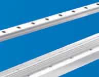
21 Heavy-ine GU System
22 Heavy-ine Guide rails GU..M, GU..MT GU...MT 90 ± 10' G H c h g sm b + 0,05 D S I 1 I GU...M 90 ± 5' 0,02 A H c h A b + 0,05 0,1 S 0,02 The longitudinal slot, made with tolerance, permits using reference elements SAG for guide positioning. H ± 0.05 h ± 0.05 S ± 0.05 D Dimensions (mm) G g b c ± 0.05 sm l l 1 Weight (kg/m) (2) GU 28 MT 19,0 11, x GU 35 MT x GU 50 MT , , , x max length in single element =6 000 mm (1) H ± 0.05 h ± 0.05 S ± 0.05 D Dimensions (mm) G g b c ± 0.05 l l 1 Weight (kg/m) (2) GU 28 M GU 35 M GU 50 M 18, , , , , max length in single element =4 020 mm (1) (1) onger rails are supplied in sections with ground butt joints - (2) Weight without holes Rails finishing - drawn, induction hardened and sandblasted tracks (MT); - drawn, induction hardened and ground (M) - Induction hardening on raceways only Hole layout - holes according to catalogue (S) - finishes to drawing (NZ) - without holes (NF) Optional features - ground one end (R) - ground both ends (RR) - chemical Nickel-plating (NW) Example of standard designation : GU 35 MT 4300 S See page 17 for standard codification 20
23 Heavy-ine Guide rollers RKU concentric eccentric 90 P SW 2 M k=1 SW 1 SW 1 De T d d 1 m S min. A I 1 The sides of the race are convex with radius R = 400. concentric RKU 55 eccentric RKUR 55 Dimensions (mm) De d (1) 1 d T m S min. P A I 1 M SW M 20 x RKU 65 RKUR M 24 x RKU 75 RKUR M 30 x RKU 95 RKUR M 36 x RKU 115 RKUR M 36 x (5) 63 (5) SW k Dynamic load (N) imit loads (N) ife coefficients C w (6) radial F r axial F a X Y Torque wrench (2) settings (Nm) Weight (kg) RKU 55 RKUR RKU 65 RKUR RKU 75 RKUR RKU 95 RKUR RKU 115 RKUR ) Housing bore tolerance: H7 2) The torque wrench settings are given for non-lubricated threads; for lubricated threads, multiply figure by 0.8 3) Standard seals: material NR, RS type 4) On request, the guide rollers can be supplied with external parts in stainless steel (suffix NX) and with Viton seals for operating temperatures up to 120 C (suffix V, not available for RKU 115). Internal rolling elements in standard bearing steel. 5) Dimensions relating to the stainless-steel rollers (suffix NX) 6) Cw basic load for 100 km 7) The guide rollers include self-locking washers and hexagonal nut (DIN 439) for fitting 8) Pressure angle α for load calculation: 45 21

24 Heavy-ine Guide wheels FKU 90 d2 De M F T d H8 m A The sides of the race are convex with radius R = 400. Dimensions (mm) De d T m A F d (4) 2 M FKU , FKU , ,0 35 FKU , ,0 44 FKU , ,0 49 FKU ,0 56 (2) 63 (2) ,0 59 Dynamic load (N) imit loads (N) ife coefficients C w (3) radial F r axial F a X Y Weight (kg) FKU FKU FKU FKU FKU ) On request, the guide rollers can be supplied with external parts in stainless steel (suffix NX) and with Viton seals for operating temperatures up to 120 C (suffix V not available for FKU 115). Internal rolling elements in standard bearing steel 2) Dimensions relating to the stainless-steel rollers (suffix NX) 3) Cw basic load for 100 km 4) To prevent rotation between roller and shaft a pin can be fitted in one of the holes d 2 positioned in the side flange 5) Pressure angle α for load calculation: 45 6) Standard seals: material NR, RS type 22
25 Heavy-ine Floating guide rollers RKU concentric eccentric 90 X M SW 2 SW 1 n P k De d d 1 T m S min. A C l 1 Dimensions (mm) concentric eccentric De d 1) 1 d T m n X S min. P A 4) C I 1 M SW 1 SW 2 k RKU 55 RKUR M 20 x RKU 65 RKUR M 24 x RKU 75 RKUR M 30 x RKU 95 RKUR M 36 x ) RKU 115 RKUR M 36 x ) Dynamic load (N) imit load (N) Torque wrench settings 2) C 3) w radial F r (Nm) RKU 55 RKUR RKU 65 RKUR RKU 75 RKUR RKU 95 RKUR RKU 115 RKUR Weight (g) 1) Housing bore tolerance: H7 2) The torque wrench settings are given for non-lubricated threads; for lubricated threads multiply figure by 0.8 3) Cw = asic load for 100 KM 4) Dimensions for stainless steel (NX) version On request the guide rollers can be supplied with external parts in stainless steel (suffix NX). Internal rolling elements in standard bearing steel Standard seals: material NR, RS type On request guide rollers can be supplied with Viton seals for operating temperatures up to 120 C (suffix V, not available for RKU 115) The guide rollers include self-locking washers and hexagonal nut (DIN 439) for fitting Pressure angle α for load calculation: 45 23
 U1 C A (1) V (1) roller axis E mounting rollers-plate X Dimensions (mm) U1 U2 F m S C A E V P Weight (g) Suggested combinations UU 55 35 12 14 40 19.8 25.5 10.0 34 20.0 38 16.5 18.")
26 Heavy-ine ubricator UU X min F M6 DIN M U2 S (1) m P M5 pf.12 (2x) U1 C A (1) V (1) roller axis E mounting rollers-plate X Dimensions (mm) U1 U2 F m S C A E V P Weight (g) Suggested combinations UU RKU 55 RKUR 55 FKU 55 UU RKU 65 RKUR 65 FKU 65 UU RKU 75 RKUR 75 FKU 75 UU RKU 95 RKUR 95 FKU 95 UU RKU 115 RKUR 115 FKU 115 1) The dimension of the plastic part refers to the centre of the regulation-slot. Allows a translation of +/- 3 mm. 2) The lubricator is supplied with the felt already lubricated. The lubricant has a mineral oil base. 3) During the mounting fix the aluminium support to the rollers plate, adjust the height of the plastic part in order to put it in contact with the raceways and than block it in that position with the M5 screws. Optional features - felt without lubricant (D) 24
 Housing bore tolerance: H7 Dimensions (mm) D d")
 I h Roller I h (mm) Guide RKU,")

27 Heavy-ine Guide pins SAG D h7 P d m6 Pin type Guide type SAG 28 GU 28 MT SAG 35 GU 35 MT SAG 50 GU 50 MT 1) Housing bore tolerance: H7 Dimensions (mm) D d (1) P Guide roller combinations (RKU, FKU, RKU) I h Roller I h (mm) Guide RKU, FKU, RKU 55 RKU, FKU, RKU 65 RKU, FKU, RKU 75 RKU, FKU, RKU 95 RKU, FKU, RKU 115 GU 28 MT ,0 GU 28 MT ,0 GU 35 MT GU 35 MT GU 50 MT GU 50 MT
28 Heavy-ine Mounting Examples GU 35 MT and rollers type RKU 75 operated on light-alloy structure. 26

29 Heavy-ine GP System
 150 60 8.1 GP 3617 MC 36 17 6.5 11 6.8 12.5 120 50 4.8 GP 4321 MC GP 5050 MC 43 50 21 50 9,0 18,0 15 26 GP 6222 MC 62 22 9,0 15 9,0 21.0 150 60 10.")
30 Heavy-ine Guide rail GP...MC D G oring layout A = = h l 1 l l g 2x45 S e oring layout h ± 0.05 S ± 0.05 Dimensions (mm) D G g e l l 1 GP 2626 MC ,0 (3) GP 3232 MC ,0 15 9,0 (3) GP 3617 MC GP 4321 MC GP 5050 MC ,0 18, GP 6222 MC ,0 15 9, GP 7232 MC ,0 24, Max length of single guide element = mm (1) Weight (2) (kg/m) GP 8222 MC ,0 20, ) onger rails are supplied in sections with ground butt joints 2) Weight without holes 3) For boring layout A only 9,0 17, (3) Rails finishing - material: C60 or C45 - induction hardened on every side - surface finished by a rough grinding (MC) Hole layout - holes according to catalogue (A or ) - finishes to drawing (NZ) - without holes (NF) Optional features - ground one end (R) - ground both ends (RR) - chemical nickel plating (NW) Example of standard designation: GP 6222 MC 4300 See page 17 for standard codification 28
 Weight (2) (kg/m) GP 2525 M 25 25 9.0 15 8.5 (3) 120 50 4.9 GP 3131 M 31 31 9.0 15 8.5 (3) 150 60 7.5 35 Dimensions (mm) 16 6.5 11 6.")
31 Heavy-ine Guide rails GP...M D G oring layout A 0,02 A 0,02 = = h l 1 l l g 1x45 A S e 0,02 oring layout GP 3516 M h ± 0.05 S ± 0.05 D G g e l l 1 Max length of single guide element = mm (1) Weight (2) (kg/m) GP 2525 M (3) GP 3131 M (3) Dimensions (mm) , GP 4220 M ,0 15 9,0 11, GP 6121 M ,0 15 9, GP 7131 M GP 8121 M , ) onger rails are supplied in sections with ground butt joints (max. length with treatment NW on request) 2) Weight without holes 3) Only available according to figure A Rails finishing - material: C60 or C45 - induction hardened and ground tracks on every side (M); Hole layout - holes according to catalogue (A or ) - finishes to drawing (NZ) - without holes (NF) Optional features - ground one end (R) - ground both ends ( RR ) - chemical Nickel-plating (NW) Example of standard designation : GP 6121 M 2070 See page 17 for standard codification 29
32 Heavy-ine Guide rollers PK concentric eccentric R C P SW 2 M k=1 SW 1 SW 1 De d d 1 m S min. A I 1 Dimensions (mm) concentric eccentric De d (1) 1 d m S min. P A C R I 1 M SW 1 SW 2 PK 52C PKR 52C M 20 x PK 62C PKR 62C M 24 x PK 72C PKR 72C M 30 x PK 90C PKR 90C M 36 x PK 110C PKR 110C M 36 x (5) 63 (5) k Dynamic load (N) C w (6) imit load (N) radial F r Torque (2) wrench setting (Nm) Weight (Kg) PK 52C PKR 52C PK 62C PKR 62C PK 72C PKR 72C PK 90C PKR 90C PK 110C PKR 110C ) Housing bore tolerance: H7 2) The torque wrench settings are given for non-lubricated threads; for lubricated threads, multiply figure by 0.8 3) Standard seals: material NR, RS type 4) On request, the guide rollers can be supplied with external parts in stainless steel (suffix NX) and with Viton seals for operating temperatures up to 120 C (suffix V, up to dimension PK 90 C included). Internal rolling elements in standard bearing steel 5) Dimensions relating to the stainless-steel rollers (suffix NX) 6) Cw basic load for 100 km 7) The guide rollers are complete with self-locking washers and hexagonal nut for fitting 30
 64 45 1 200 42 4,0 49 FK 110C 110 35 60 63 (3) 72 48 1 200 52 4,0 59 Dynamic load (N) C w (4)")
33 Heavy-ine Guide wheels FK R Rotelle di guida FK De M F d2 d H8 C A FK 52C Dimensions (mm) De d A C R F d 2 M FK 62C ,0 35 FK 72C ,0 44 FK 90C (3) ,0 49 FK 110C (3) ,0 59 Dynamic load (N) C w (4) imit load (N) radial F r Weight (kg) FK 52C FK 62C FK 72C FK 90C FK 110C ) Standard seals: material NR, RS type 2) On request, the guide rollers can be supplied with external parts in stainless steel (suffix NX) and with Viton seals for operating temperatures up to 120 C (suffix V, up to dimension FK 90 C included). Internal rolling elements in standard bearing steel 3) Dimensions relating to the stainless-steel rollers (suffix NX) 4) Cw basic load for 100 km 5) To prevent rotation between roller and shaft a pin can be fitted in one of the holes d 2 positioned in the side flange 31
34 Heavy-ine Guide rollers GC concentric GC GC...EE with plastic seals GC...EEM with metal shields De t r A 2 e 1 t d M esecution EE, EEM Perni folli a rullini GCR l f eccentric GCR GCR...EE with plastic seals GCR...EEM with metal shields De M t r A l 1 S k 1 t d d 1 M 1 4 S Holes (1) and (2) beginning from De=30 mm f l GCR GCR 62 Dimensions (mm) (1) De A max d d 1 (7) k max l max f pitch r min t e M (6) M 1 P (2) l 1 GC 19 GCR ,0 GC 22 GCR , * ,0 GC 24 GCR , * ,0 GC 26 GCR , * ,0 GC 28 GCR , * ,0 GC 30 GCR , * ,0 GC 32 GCR , * ,0 GC 35 GCR , , * ,0 GC 40 GCR , , * 1, ,0 GC 47 GCR , , * 1, GC 52 GCR , , * 1, GC 62 GCR , , * 1, ,0 * These threads may be supplied with pitch of 1 mm (clamping torque 13 Nm) - Housing bore tolerance: H7 - The guide rollers are complete with washers and hexagonal nut for fitting 32
35 Heavy-ine Guide rollers GC 1) Specification for followers with cylindrical outer ring: GC, GCR, GC...EE, GC...EEM, GCR...EEM. On request the followers can be supplied possessing a screw driver slot at the threaded end of the stud (suffix AK). 2) Followers with outer diameter up to 28 mm included possess a screw driver slot on the head. Followers with outer diameter from 30 to 52 mm included can possess the screw driver slot or the hexagonal socket. For outer diameter above 52 mm the followers possess the hexagonal socket. 3) The load shown is limited by the strengths of the stud and outer ring. DIRECTION FOR ADJUSTMENT OF THE EXCENTER NA P 4) With oil lubrication of followers without seals GC, GCR, GC e GCR, these speeds can be increased by 30% for continuous rotation or up to 50% momentarily. 5) These torques are shown for dry threads. For lubricated threads, take 0,8 of these values. 6) Minimum recommended abutment diameter in case of high axial load or in the presence vibrations. 7) The eccentric collar is tightly fitted on the follower stud. 8) C w dynamic load for 100 Km S min max R Dynamic load (N) C w (8) imit load (3) (N) GC... GCR... Dyn. F r Stat. F or Dyn. F r Stat. F or Speed limit grease lubrication r.p.m. (4) Torque wrench setting (Nm) (5) GC... GCR , , , , , , , ,5 25, ,5 25, Favourite sizes are: 19/22/26/30/35/40/52/62 Track rollers in stainless steel are available on stock in the following sizes: 19/26/30/35/40 (suffix NX). Internal rolling elements in standard bearing steel 33
 De Di A max D 1 M (1) min r min r 1 min R FG 6 19 19 6 11 12 8.5 12 0.3 0.3 160 FG 10 30 30 10 14 15 13.8 19.")
36 Heavy-ine Cam followers FG (needle) and FGU (roller) FG series without seals FG EEM series with metal shields FGU FGU...MM series: with metal shields A r A r De Di r 1 D 1 r 1 Di D 1 De R R Dimensions (mm) De Di A max D 1 M (1) min r min r 1 min R FG FG FG FG FG FG FG FG FG FG FG FGU FGU FGU FGU
37 Heavy-ine Cam followers FG (needle) and FGU (roller) 1) Minimum recommended abutment diameter. 2) Cw dynamic load 100 KM. These capacities are to be used for all types when the convex outer ring rotates directly on a cam. They take account of the repetitive loads on the follower and consequent deformation of the outer ring. 3) The load shown is limited by the strength of the outer ring when mounted in a housing. 4) With oil lubrication of followers without seals FG, FG types, these speeds can be increased by 30% for continuous rotation or, up to 50% momentarily Dynamic load (N) (2) imit loads (3) (N) Speed limit grease lubrication (4) r.p.m. Cw Dyn. F Sta. Fo
 U2 S P U1 C V (1) roller axis E mounting rollers plate X Dimensions (mm) U1 U2 F m S C E V P Weight (g) Suggested combinations UP 52 33.5 12 14 40 19.8 25.5 10 32.5 38 16.5 18.")
38 Heavy-ine ubricator UP M6 DIN M X min. (1) F m M5 pf.12 (2x) U2 S P U1 C V (1) roller axis E mounting rollers plate X Dimensions (mm) U1 U2 F m S C E V P Weight (g) Suggested combinations UP PK 52 C PKR 52 C FK 52 C UP PK 62 C PKR 62 C FK 62 C UP PK 72 C PKR 72 C FK 72C UP PK 90 C PKR 90 C FK 90 C UP PK 110 C PKR 110 C FK 110 C 1) The dimension of the plastic part refers to the centre of the regulation slot. The regulation slot allows a translation of +/- 3 mm 2) The lubricator is supplied with the felt already lubricated. The lubricant has a mineral oil base 3) During the mounting fix the aluminiun support to the rollers plate, adjust the height of the plastic part in order to put it in contact with the raceways and than block it in that position with the M5 screws. Optional features - felt without lubricant (D) 36
39 Heavy-ine Guide rollers combinations ayout 1 ayout 2 hole pattern A and only hole pattern ayout 1 GC PK/FK GP2626MC / GP2525M GP3232MC / GP3131M GP3617MC / GP3516M GP4321MC / GP4220M GP5050MC GP6222MC / GP6121M GP7232MC / GP7131M GP8222MC / GP8121M ayout 1 FG/FGU GP2626MC / GP2525M GP3232MC / GP3131M GP3617MC / GP3516M GP4321MC / GP4220M GP5050MC GP6222MC / GP6121M GP7232MC / GP7131M GP8222MC / GP8121M ayout 2 GC PK/FK GP3617MC / GP3516M GP4321MC / GP4220M GP6222MC / GP6121M GP7232MC / GP7131M GP8222MC / GP8121M ayout 2 GC GP3617MC / GP3516M GP4321MC / GP4220M GP6222MC / GP6121M GP7232MC / GP7131M GP8222MC / GP8121M In the tables above the suggested combinations. Other combinations are possible but guide rollers must not run over the holes. 37


40 Heavy-ine Mounting examples MARE MACHINERY Heavy-ine systems GU and GP 38


41 Rolbloc Rolbloc System
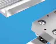
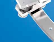
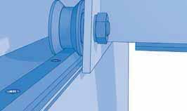
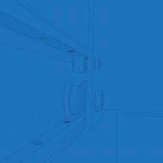
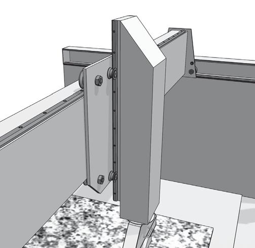
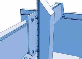
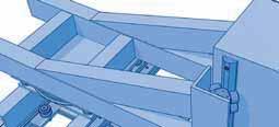
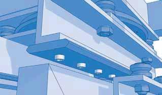
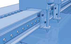
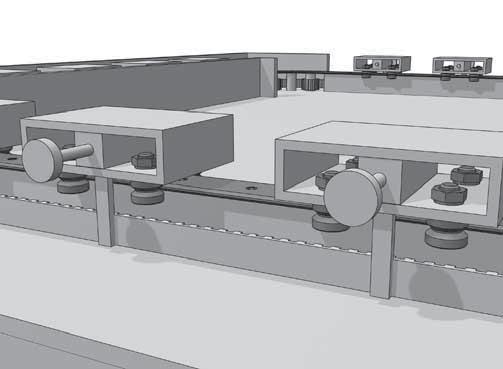
42 Rolbloc Rolbloc system The carriages based on Rolbloc s system are recommended for applications with heavy loads, high frequency of work and aggressive environment (dust, abrasive). For the profiled guide rollers, the contact beween the rollers and the rail takes place on the ground raceways, which are inclined respect the rotation axis of the guide roller. Due to this inclination angle in the contact area there is a dragging proportional to the dimension of the contact area and to the value of the inclination angle. In the ROOC system the rotation axes of the roller guides are parallel to the raceways of the rail, with the following pure rolling. The pure rolling recudes the superficial stress and the effects of the dust between the surfaces. Technical features ROOC carriages 2.. and 4.. are composed by a body in burnished steel on which are mounted two or four roller guides equipped wi th tapered rollers (similar to flat roller guides type PK..C). The final part of the code (that can be 52, 75 or 115) shows the external diameter of the roller guides. M carriages are composed by an alluminium body provided, on one side, with four threaded screws that allow the direct mounting on the fixing plate. esides, in order to facilitate the aligning, there are also two pin screws. The body is equipped with guide rollers with a double row angular contact ball bearing. On the body are mounted three guide rollers according to the following combinations: M(R) M(R) M components are checked with the same method used for ROOC, but it is very important to consider the exact bearing ratings that must be correct for the load direction. When the axial load (perpendicular to the fixing side of the carriage, or parallel to the fixing side of the rail) is in the direction of the two coupled guide rollers, as for the sketch above, you must use the coefficient with the suffix 2 (F a2, Y 2 ), otherwise with the suffix 1 (F a1, Y 1 ). Mounting instructions For the mounting of the carriages or M, with two, three and four guide rollers, are necessary at least two carriages on every rail. A slider realised with only two carriages for rail is not steady (see sketch below). Ix Fixing side Main load direction M(R) Main load direction M 335-1: three concentric guide rollers, of which one on the fixing side; M 335-2: three concentric guide rollers, of which two on the fixing side; MR 335-1: three concentric guide rollers, of which one on the fixing side; MR 335-2: three concentric guide rollers, of which two on the fixing side. YES NO Pay the maximum attention during the setting of the eccentricity of the eccentric guide rollers in order to avoid excessive preloads that can reduce the lifetime of the system. Setting the eccentric guide rollers by rotating the stud anticlockwise (respect the head side of the guide roller). M carriages are dissymmetrical components. In order to fully utilize the load capacity of the carriages it is necessary to consider the main load direction and than put the two coupled guide rollers in that direction. 40
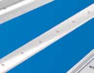
43 Rolbloc Guide rails GU..M, GU..MT 90 ± 10' GU 35 MT GU 62 MT GU 80 MT G H c h g sm b + 0,05 S 90 ± 5' GU 62 M GU 35 M GU 80 M I 1 D I 0,02 A H c h A b + 0,05 0,1 S 0,02 The longitudinal slot of rail GU 35 permits using reference elements SAG for guide positioning. H ± 0.05 h ± 0.05 S ± 0.05 D Dimensions (mm) G g b c ± 0.05 sm l l 1 Weight (kg/m) (2) GU 35 MT x GU 62 MT x GU 80 MT (3) x max length in single element = mm (1) H ± 0.05 h ± 0.05 S ± 0.05 D Dimensions (mm) G g b c ± 0.05 l l 1 Weight (kg/m) (2) GU 35 M GU 62 M GU 80 M max length in single element = mm (1) (1) onger rails are supplied in sections with ground butt joints - (2) Weight without holes - (3) Max length in single element mm for GU 80 MT Rails finishing - drawn, induction hardened and sandblasted tracks (MT); - drawn, induction hardened and ground (M) - induction hardening on raceways only Hole layout - holes according to catalogue (S) - finishes to drawing (NZ) - without holes (NF) Optional features - ground one end (R) - ground both ends ( RR ) - chemical Nickel-plating (NW) Example of standard designation : GU 62 MT 4300 S See page 17 for standard codification 41
 Pin-hole 4H7 (depth 6 mm) = = Ih Z b Guida Pattino Ih(mm) M/MR M(R) 335-2 (carriage with 2 guide rollers on the fixing side) S GU 35 MT GU 35 M 41,5 40,6")
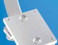
44 = = = = Rolbloc Carriages M C e RADIA Direction Pin-hole 4H7 (depth 6mm) A m b Z = = p f AXIA Direction = = M(R) (carriage with 1 guide roller on he fixing side) S De k k T C e M(R) (carriage with three guide rollers) Pin-hole 4H7 (depth 6 mm) = = Ih Z b Guida Pattino Ih(mm) M/MR M(R) (carriage with 2 guide rollers on the fixing side) S GU 35 MT GU 35 M 41,5 40,6 concentric eccentric Dimensions (mm) A C S m e b p f k (2) T Z De Weight (kg) M M MR MR M Dynamic load (N) Cw (3) radial Fr imit loads (N) axial Fa Fa1 (5) Fa2 (6) X ife coefficients Y Y1 (5) Y2 (6) M MR M MR ) Standard shields metallic ZZ 2) Maximum value of eccentricity for carriages MR, where all the guide rollers are eccentric 3) Cw basic load for 100 km, radial load 4) Pressure angle α for load calculation: 45 5) earing ratings you must use when the axial load is in the direction of the side with one guide roller only 6) earing ratings you must use when the axial load is in the direction of the side with two guide rollers 42
 A C P P 1 P 2 V m e u f Q T Z Weight (kg) 2 52 136 90 56 54 14 16 M4x 7 70 40 8 M 8 12 43 47 2.4 4 520 136 90 112 54 14 16 M4x 7 70 48 8 M 8 12 43 47 4.")
45 Rolbloc Carriages u C e 2... two guide rollers block A m P V f Q Z P 1 P 2 T C u e e 4... four guide rollers block Q Z Dimensions (mm) A C P P 1 P 2 V m e u f Q T Z Weight (kg) M4x M M4x M M5x M M5x M M5x M M5x M Dynamic load (N) imit loads (N) C w (3) Radial F r (4) Axial F a (5) X ife coefficients Y ) Standard seals: material NR, RS type 2) On request, the guide rollers can be supplied in stainless steel (suffix NX) and with Viton seals for operating temperatures up to 120 C (suffix V, up to dimension included). Internal rolling elements in standard bearing steel 3) C w basic load for 100 km, load perpendicular to the roller side fixing surface 4) oads perpendicular to the roller side fixing surface 5) oads parallel to the roller side fixing surface 6) Pressure angle α for loads checking calculation: 45 43

46 Rolbloc Adjustment plates PR A setting screw S =A ± 0.7 W A Ih A Dimensions (mm) W A Weight (kg) Combination with ROOC carriages PR PR PR PR PR PR The adjusting plates allows to easily set the proper component preload during the mounting on the machine. The two steel plates are placed in between the standard ROOC and the mounting surface. Setting is done by the setting screw before the final tightening of the screws used to mount the ROOC. Dimension W of plates is 2 mm lower than the block of ROOC. Use the ROOC side are reference for the block position. When the plates are set in the mid position (thickness 13.5 mm) they can be shifted 10 mm from the block centreline. The possible shift is reduced with the regulation since it become null at the end of allowed setting, minimum or maximum height. Consider 10 mm of space over the plate length on each side (20 mm over the block length) to use the full thickness setting capability +/- 0,7 mm 44

47 Rolbloc Guide/carriage combinations M l h Ih Carriage I h (mm) Guide GU 35 MT GU 35 MT GU 62 MT GU 62 MT M / MR , GU 80 MT GU 80 MT , Mounting examples 45


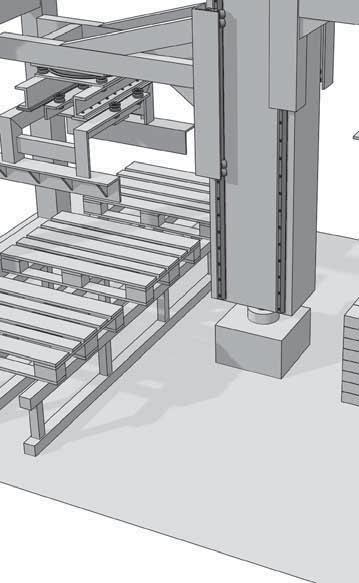


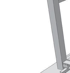
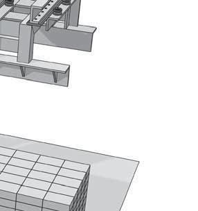
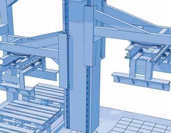

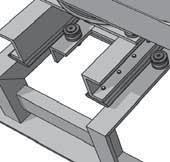


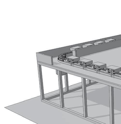
48 Rolbloc Mounting example Palletising equipment Rolbloc V-ine Multi-Motion-ine 46

49 V-ine FS System

50 V-ine Guide rails FS..MT c from FS 19 MT up to FS 62 MT 80 = D = d H h l 1 l l a S e FS 72 MT H ± 0.1 h ± 0.1 S ± 0.1 d (3) Dimensions (mm) D c (3) e a l l 1 Weight (2) (kg/m) FS 19 MT FS 22 MT FS 32 MT FS 35 MT FS 40 MT FS 47 MT FS 52 MT FS 62 MT FS 72 MT Maximum length of single guide element = mm (1) 1) onger rails are supplied in sections with ground butt joints - 2) Weight without holes 3) Standard layout without pin holes (pin holes only on request) Rails finishing - drawn,induction hardened and sandblasted tracks (MT); - induction hardening on raceways only Hole layout - holes according to catalogue (S) - finishes to drawing (NZ) - without holes (NF) Optional features - ground one end (R) - ground both ends ( RR ) - chemical Nickel-plating (NW) - pin holes Example of standard designation : FS 52 MT 5280 S See page 17 for standard codification 48
 FS 32 M 42.86 41 6 6 6.5 15 90 30 47.86 FS 40 M 63.58 61 8 6 9 20 90 30 FS 47 M (4) 78.58 76 10 6 11.5 20 90 30 FS 52 M 89.78 87 12 8 13.5 20 90 30 FS 62 M 104.76 S ± 0.")
51 V-ine Guide rails FS..M c from FS 19 M up to FS 62 M 80 = D = d A 0,02 H h l 1 l l a S A e FS 72 M FS 19 M FS 22 M (4) FS 35 M (4) H ± h ± Dimensions (mm) FS 32 M FS 40 M FS 47 M (4) FS 52 M FS 62 M S ± 0.05 d (3) D c (3) e a l l Maximum length of single guide element = mm (1) Weight (2) (kg/m) FS 72 M ) onger rails are supplied in sections with ground butt joints - 2) Weight without holes 3) Standard layout without pin holes (pin holes only on request) - (4) Size 22, 35 and 47 available in stainless steel (NX) Rails finishing - drawn, induction hardened and ground profile (M); - induction hardening on raceways only Hole layout - holes according to catalogue (S) - finishes to drawing (NZ) - without holes (NF) Optional features - stainless steel (NX) (4) - ground one end (R) - ground both ends (RR) - chemical Nickel-plating (NW) - pin holes Example of standard designation : FS 40 M 2760 S See page 17 for standard codification 49
 D c (3) e l l 1 Weight (2) (kg/m) FSH 22 MT FSH 32 MT FSH 40 MT FSH 52 MT FSH 62 MT FSH 72 MT 23.90 29.90 37.20 40.75 50.75 60.85 23.0 5.8 5 6.5 15 9 90 30 1.0 29.0 6.8 6 6.")
52 V-ine Guide rails FSH..MT, FSX..MT FSH 80 FSX 90 c H h D d e S l 1 l l H ± 0.1 h ± 0.1 S ± 0.1 d (3) Dimensions (mm) D c (3) e l l 1 Weight (2) (kg/m) FSH 22 MT FSH 32 MT FSH 40 MT FSH 52 MT FSH 62 MT FSH 72 MT FSX 90 MT Maximum length of single guide element = mm (1) 1) onger rails are supplied in sections with ground butt joints - 2) Weight without holes 3) Standard layout without pin holes (pin holes only on request) Rails finishing - drawn, induction hardened and sandblasted tracks (MT); - induction hardening on raceways and base only Hole layout - holes according to catalogue (S) - finishes to drawing (NZ) - without holes (NF) Optional features - ground one end (R) - ground both ends ( RR ) - chemical Nickel-plating (NW) - pin holes Example of standard designation : FSH 52 MT 5280 S See page 17 for standard codification 50
 D c (3) e l l 1 Weight (2) (kg/m) FSH 19 M FSH 22 M FSH 32 M FSH 40 M FSH 52 M FSH 62 M FSH 72 M FSX 90 M 18.98 22.93 28.93 36.29 39.39 49.38 59.49 61.79 18.5 4.5 4 6.")
53 V-ine Guide rails FSH...M, FSX...M FSH 80 FSX 90 c 0,02 A H h D d e A l 1 l l S H ± 0.05 h ± 0.1 S ± 0.05 d (3) Dimensions (mm) D c (3) e l l 1 Weight (2) (kg/m) FSH 19 M FSH 22 M FSH 32 M FSH 40 M FSH 52 M FSH 62 M FSH 72 M FSX 90 M Maximum length of single guide element = mm (1) 1) onger rails are supplied in sections with ground butt joints - 2) Weight without holes 3) Standard layout without pin holes (pin holes only on request) Rails finishing - drawn, induction hardened and ground profile (M); - induction hardening on raceways and base only Hole layout - holes according to catalogue (S) - finishes to drawing (NZ) - without holes (NF) Optional features - ground one end (R) - ground both ends ( RR ) - chemical Nickel-plating (NW) - pin holes Example of standard designation : FSH 40 M 2760 S See page 17 for standard codification 51
54 V-ine Guide rollers FR..EU concentric eccentric 80 M SW 2 k P SW 3 SW 1 De d d 1 T m S min. A l 1 The sides of the race are slightly convex Dimensions (mm) concentric eccentric De d (1) 1 d T m S min P A I 1 M SW 1 SW 2 SW 3 k FR 22 EU (4) FRR 22 EU (4) 22 9 M 6 x FR 32 EU (4) FRR 32 EU (4) M 10 x FR 40 EU (4) FRR 40 EU (4) M 12 x FR 52 EU FRR 52 EU M 16 x FR 62 EU FRR 62 EU M 20 x Dynamic load (N) imit loads (N) ife coefficients C w (3) radial F r axial F a X Y Torque wrench settings (2) (Nm) Weight (g) FR 22 EU FRR 22 EU FR 32 EU FRR 32 EU FR 40 EU FRR 40 EU FR 52 EU FRR 52 EU FR 62 EU FRR 62 EU ) Housing bore tolerance: H7 2) The torque wrench settings are given for non-lubricated threads; for lubricated threads, multiply figure by 0.8 3) Cw basic load for 100 km 4) FR/R 22, 32, 40 are available in stainless steel (NX) The guide rollers are complete with self-locking washers and hexagonal nut (DIN439) for fitting Pressure angle α for load calculation: 40 NR seals RS type 52
55 V-ine Guide Rollers FR..EU AS, FR..EU AZ AS concentric 80 SW eccentric k d 1 Q De T d d 1 M s m l 1 A l m o AZ 80 SW G k De T d d 1 M m o m l 1 h A l lg Dimensions (mm) concentric eccentric De d1 (1) d (2) T m A l 1 l h M SW G o Q Ig (7) s k FR 22 EU AS (6) FRR 22 EU AS (6) 22 6 M FR 32 EU AS (6) FRR 32 EU AS (6) 32 9 M (4) 0.5 FR 40 EU AS (6) FRR 40 EU AS (6) M (4) 1 FR 52 EU AS FRR 52 EU AS M (4) 1.5 FR 62 EU AS FRR 62 EU AS M (5) 1.5 FR 22 EU AZ (6) FRR 22 EU AZ (6) FR 32 EU AZ (6) FRR 32 EU AZ (6) FR 40 EU AZ (6) FRR 40 EU AZ (6) FR 52 EU AZ FRR 52 EU AZ FR 62 EU AZ FRR 62 EU AZ Guide roller size Dynamic load (N) imit loads (N) ife coefficients Weight AS (g) Weight AZ (g) On request for AZ screw DIN7984 Cw (3) radial F r axial F a X Y M 5 x M 8 x M10 x M14 x M16 x 65 1) Housing bore tolerance: H7 2) Safety threads SPIRAOCK 3) Cw basic load for 100 km 4) Guide roller with washers DIN134 without screw DIN7984 or DIN912 5) Guide roller with washers DIN125 without screw DIN7984 or DIN912 6) FR/R 22, 32, 40 AS and AZ are available in stainless steel (NX) 7) AZ: minimum length of the thread engaged steel = 1 x d - cast iron = 1.25 x d aluminium = 2 x d AS screws length: min = d+o+s; max = m+4+o+s NR seals RS type Pressure angle α for load calculation: 40 53
56 V-ine Guide rollers FRN..EI concentric eccentric 80 M SW 2 P SW 1 SW 1 k De d d 1 T m S min. A l 1 The sides of the race are slightly convex concentric FRN 19 EI (8) eccentric FRNR 19 EI (8) De Dimensions (mm) d (1) 1 d T m S min. P A I 1 M SW M 5 x ,5 (10) 8 FRN 22 EI (8) FRNR 22 EI (8) 22 9 M 6 x , (10) 10 FRN 32 EI (8) FRNR 32 EI (8) M 10 x , FRN 40 EI (9) FRNR 40 EI (9) M 12 x ,5 32, SW 2 k ,5 Dynamic loads (N) imit loads (N) C (4) wr C (4) wa radial F r axial F a Torque wrench (2) settings (Nm) Weight (g) FRN 19 EI FRNR 19 EI FRN 22 EI FRNR 22 EI ,5 53 FRN 32 EI FRNR 32 EI ,3 160 FRN 40 EI FRNR 40 EI , ) Housing bore tolerance: H7 2) The torque wrench settings are given for non-lubricated threads; for lubricated threads, multiply figure by 0.8 3) On request, the guide rollers can be supplied with external parts in stainless steel (suffix NX). Internal rolling elements in standard bearing steel. 4) Cw basic load for 100 km 5) The guide rollers are complete with self-locking washers and hexagonal nut (DIN 439) for fitting 6) Pressure angle α for load calculation: 40 7) Standard Viton seals to fit temperature up to 120 C 8) ubrication hole only on head side 9) ubrication hole also on stud side 10) For size 19 and 22: screw driver slot on the head and hexagonal socket at the threaded end of the stud 54
57 V-ine Guide rollers RKY.., RKX.. concentric eccentric RKX..90 RKY..80 P SW 2 M k=1 SW 1 SW1 De d d 1 T m S min. A I 1 The sides of the race are convex with radius R = 400. concentric RKY 52 RKY 62 eccentric RKYR 52 Dimensions (mm) De d (1) 1 d T m S min. P A I 1 M SW M 20 x RKYR M 24 x RKY 72 RKYR M 30 x RKX 90C RKXR 90C M 36 x RKX 110C RKXR 110C M 36 x (6) 63 (6) SW k Dynamic load (N) imit loads (N) ife coefficients C w (5) radial F r axial F a X Y Torque wrench (2) settings (Nm) Weight (kg) RKY 52 RKYR RKY 62 RKYR RKY 72 RKYR RKX 90C RKXR 90C RKX 110C RKXR 110C ) Housing bore tolerance: H7 2) The torque wrench settings are given for non-lubricated threads; for lubricated threads, multiply figure by 0.8 3) Standard seals: material NR, RS type 4) On request, the guide rollers can be supplied with external parts in stainless steel (suffix NX) and with Viton seals for operating temperatures up to 120 C (suffix V, up to dimension RKX 90 C included). Internal rolling elements in standard bearing steel 5) Cw basic load for 100 km 6) Dimensions relating to the stainless-steel rollers (suffix NX) 7) The guide rollers are complete with self-locking washers and hexagonal nut (DIN 439) for fitting 8) Pressure angle α for load calculation: guide rollers RKY 40 - guide rollers RKX 45 55
 63 (2) 60 72 52 4,0 59 Weight (kg) 0.5 0.")
58 V-ine Guide wheels FKY.., FKX.. FKX..90 FKY..80 d2 De M F d H8 T m A The sides of the race are convex. Dimensions (mm) De d T m A F d 2 M FKY 52C , FKY 62C ,0 35 FKY 72C , ,0 44 FKX 90C , ,0 49 FKX 110C ,0 56 (2) 63 (2) ,0 59 Weight (kg) FKY 52C FKY 62C FKY 72C FKX 90C FKX 110C Dynamic load (N) imit loads (N) ife coefficients C (3) w radial F r axial F a X Y ) On request, the guide rollers can be supplied with external parts in stainless steel (suffix NX) and with Viton seals for operating temperatures up to 120 C (suffix V, up to dimension FKX 90 C included). Internal rolling elements in standard bearing steel 2) Dimensions relating to the stainless-steel rollers (suffix NX) 3) Cw basic load for 100 km 4) To prevent rotation between roller and shaft a pin can be fitted in one of the holes d 2 positioned in the side flange 5) Pressure angle α for load calculation: guide rollers FKY 40 - guide rollers FKX 45 6) Standard seals: material NR, RS type 56
59 V-ine Floating guide rollers FR..EU concentric eccentric 80 X M SW 2 n k P SW 3 SW 1 De d d 1 T m S min. A l 1 The race ways are slightly convex Dimensions (mm) concentric eccentric De d 1) 1 d T m S min P A l 1 M n X SW 1 SW 2 SW 3 k FR 22 EU 5) FRR 22 EU 5) 22 9 M6 x FR 32 EU 5) FRR 32 EU 5) M10 x FR 40 EU 5) FRR 40 EU 5) M12 x FR 52 EU FRR 52 EU M16 x FR 62 EU FRR 62 EU M20 x Dynamic load (N) imit load (N) imit load Inox version (N) NX C w 4) radial F r radial F r Torque wrench setting 2) (Nm) FR 22 EU FRR 22 EU FR 32 EU FRR 32 EU FR 40 EU FRR 40 EU FR 52 EU FRR 52 EU FR 62 EU FRR 62 EU Weight (g) 3) 1) Housing bore tolerance: H7 2) The torque wrench settings are given for non-lubricated threads; for lubricated threads multiply figure by 0.8 3) Weight without fittings 4) Cw = asic load for 100 Km 5) Dimensions for stainless steel (NX) version Standard seals: material NR, RS type Guide rollers include self-locking washers and hexagonal nut (DIN 439) Pressure angle α for load calculation: 40 57
60 V-ine Floating guide rollers RKX, RKY concentric eccentric X RKX..90 RKX..80 M SW 2 SW 1 n k P De d R d 1 T m S min. A C l 1 Dimensions (mm) concentric eccentric De d 1) 1 d T m ± X S min P A C l 1 M n SW 1 SW 2 k RKY 52 RKYR M 20 x RKY 62 RKYR M 24 x RKY 72 RKYR M 30 x RKX 90 RKXR M 36 x ) RKX 110 RKXR M 36 x ) Dynamic load (N) imit load (N) Torque wrench setting Cw 3) radial F r (Nm) 2) RKY 52 RKYR RKY 62 RKYR RKY 72 RKYR RKX 90 RKXR RKX 110 RKXR ) Housing bore tollerance: H7 2) The torque wrench settings are given for non-lubricated threads; for lubricated threads multiply figure by 0.8 3) Cw = asic load for 100 Km 4) Dimensions for stainless steel (NX) version Weight (g) On request, the guide rollers can be supplied with external parts in stainless steel (suffix NX). Internal rolling elements in standard bearing steel. Standard seals: material NR, RS type On request, the guide rollers can be supplied with viton seals for operating temperatures up to 120 C (suffix V) not available for RKX 110) Pressure angle α for load calculation: 40 58
61 V-ine Spacers for FS and FSH Ø H Ø D Dimensions (mm) Suggested combinations Ø ØD H DIST FS FS19, FSH19 DIST FS FS22, FSH22, FSR22 DIST FS FS32 DIST FS FS35, FSR35 DIST FS FS40 DIST FS FS47, FSR47 DIST FS FS52 DIST FS FS62 DIST FS FS72, FSH72 DIST FSH FSH32 DIST FSH FSH40 DIST FSH FSH52 DIST FSH FSH62 DIST FSX FSX90 The spacers, mounted between the guide and the supporting structure, guarantee adequate distance for the sliding of the rollers. The spacers DIST are designed for guides FS and FSH of V-ine and guides FSR of Multi-Motion-ine. Finishing - anodized aluminium Optional features - steel 59

62 V-ine ubricator UY for FS guide rollers up to size 40 guide roller Sec DD 80 mounting rollers plate X Dimension (mm) U F m A C P Vf Vr Weight (g) UY M3x12 M4 10 FR UY M3x12 M4 10 FR UY M3x12 M4 15 FR UY M4x12 M5 30 FR Suggested combinations 1) The lubricator is supplied with the felt already lubricated. The lubricant has a mineral oil base 2) At the mounting, insert the screws inside the rollers plate, without tighten them, adjust the height of the plastic part in order to put it in contact with the raceways and then block it 3) The screws Vf for the frontal mounting are included in the packaging. Arrange two thread holes for dimension Vf in the mounting rollers plate 4) The screws for the mounting on the nut side of the roller are not included in the packaging. Arrange on the mounting rollers plate the holes in order to insert te screws Vr Optional features - felt without lubricant (D) 60
 12 14 40 19.8 25.5 10.0 34.5 24.5 38 16.5 18.5 38.5 14 12 40 20.8 25.5 10.0 34.5 24.5 38 18.5 16.5 Weight (g) 65 Suggested combinations RKY 52 RKYR 52 FKY 52 FR 52 EU FRR 52 EU.")
63 V-ine ubricator UY, UX for FS guide rollers size 52 and higher M6 DIN M X min. U2 S (1) F m P M5 pf.12 (2x) U1 C A (1) V (1) roller axis E mounting rollers plate UY 52 UY 62 X 33.5 Dimensions (mm) Weight (g) 65 Suggested combinations RKY 52 RKYR 52 FKY 52 FR 52 EU FRR 52 EU...AS/AZ RKY 62 RKYR 62 FKY 62 FR 62 EU FRR 62 EU...AS/AZ UY RKY 72 RKYR 72 FKY 72 UX 90 UX 110 U1 U2 F m S C A E V P ) The dimension of the plastic part refers to the centre of the regulation slot. The regulation slot allows a translation of +/- 3 mm 2) The lubricator is supplied with the felt already lubricated. The lubricant has a mineral oil base 3) During the mounting fix the aluminium support to the rollers plate, adjust the height of the plastic part in order to put it in contact with the raceways and than block it in that position with the M5 screws RKX 90C RKXR 90C FKX 90C RKX 110C RKXR 110C FKX 110C Optional features - felt without lubricant (D) 61
64 V-ine Guide rollers combination I y I h FS FSH / FSX Guide rollers FR...EU, FR...EU AS, FR...EU AZ, FRN...EI, RKY, RKX, FKY, FR..EU, RKX, RKY I y (mm) Guide roller size I h (mm) Guide roller size FS..M FS 19 M 35 FS 22 M 41.9 FS 32 M FS 35 M FS 40 M FS 47 M FS 52 M FS 62 M FS 72 M * * * * FSH..M, FSX..M FSH 19 M 26 FSH 22 M *29.9 FSH 32 M FSH 40 M FSH 52 M FSH 62 M FSH 72 M FSX 90 M * * * * FS..MT Guide roller size I y (mm) FS 19 MT FS 22 MT 44.2 FS 32 MT 67.4 FS 35 MT 72.4 *78 FS 40 MT 93.7 FS 47 MT * FS 52 MT *135.5 FS 62 MT FS 72 MT * FSH..MT, FSX..MT Guide roller size I h (mm) FSH 22 MT FSH 32 MT 41.7 FSH 40 MT * FSH 52 MT * FSH 62 MT * FSH 72 MT * FSX 90 MT * possible combination 62


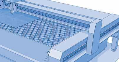
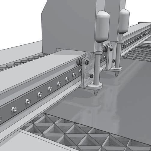
65 V-ine Mounting examples Waterjet cutting machine V-ine 63


66 V-ine Mounting examples Portable loader for steel sheet V-ine Heavy-ine 64

67 Multi-Motion-ine FSR System


68 Multi-Motion-ine Circular systems Nadella proposes several circular rails based on the FS family of profiles. The rails can be used as an entire circumference, or single sectors, or joined together with straight pieces of rail in order to obtain oval or ring circuits. Guide Sector Ring circuit the rail. The extent of the clearance depends on the dimensions of the rail, of the roller guides and of the carriage. ecause of this clearance it is not possible to have an accurate positioning of the carriage during the passage between straight and circular stretch and therefore, in fast application, there will be vibration, noise and overload of the roller guides. - This kind of carriages, with fixed guide rollers, can be used only for a single specific radius throughout the circuit. To use a carriage with fixed guide roller positions you can't have circular stretches with different radii. To define the design for holes of the fixed rollers please contact the Nadella Technical Service. Generic circuit Oval circuit The rails are steel, induction hardened on the raceways, with the same section dimensions as straight FS..M rails. In the circuits the rails are joined together with alignment blocks that allow easy precise mounting. All the pieces of the circuit are supplied appropriately marked in order to avoid mistakes during joining. For protection against corrosion Nadella proposes nickel plating (option NW) for both straight and circular pieces. In addition to the standard dimensions in the table it is possible to realize rings with different sections or radii in order to satisfy specific demands. Guide rollers Any guide rollers of the FS family of products can be used in combination with the circular rails. Steering Carriages The contraindications for the carriage with guide rollers in fixed positions can be resolved by using the steering carriage. Guide rollers are mounted in pairs on steering arms that are free to rotate in order to always be transversal to the rail in every point of the circuit. The carriage won't have clearance at any point in the circuit improving transition area accuracy and reduce running noise. The studs of the steering carriage are fitted with needle bearings and seals for lubricant retention and protection. The tightening of the stud is obtained by the full tightening of the nut, and guarantees the best locking. Carriage Carriages for circular rails can be realized with guide rollers in fixed position or mounted on steering arms. Carriages with guide rollers in fixed positions You can set up the distance between the centres of the guide rollers of a carriage with fixed guide rollers in order to obtain clearance-free running both on the straight and on the circular stretch of a circuit. The resulting carriage, normally a simple table with four holes for the housing of the guide rollers, will be simple and compact; there are, however, some contraindications: - In the passage from the straight stretch to the circular one (and vice versa), when two guide rollers are engaged on the straight portion and two on the circular one, there will be clearance between the carriage and 66
69 Multi-Motion-ine Circular rails FSR..M Pin hole Detail A (see following page) d 80 D Fixing hole I A f R1 h H R2 R3 S A I f d H7 D R1* R2* R3* n fixing holes/360 n pin holes/360 h H S FSR22M ,5 45, FSR22M ,25 30,5 25, FSR22M ,55 30,5 25, FSR35M , FSR35M , FSR47M-400 9,55 18,5 18, FSR47M-500 9,55 18,5 18, * R1, R2, R3 are radius Rails finishing - steel - induction hardened on the raceways Hole layout - holes according to catalogue (S) - finishes to drawing (NZ) Optional features - stainless steel (NX) - nickel plating (NW) - spacers for rails FS (page 58) Example of standard designation: FSR35M Circular rail sector FSR35M, radius R2 225 mm, sector angle
70 Multi-Motion-ine Alignment blocks for FSR Joint cut between the curve piece and the straight piece Detail A: drilling on the joint G t Theoretical line of joint alignment block e C Joint cut (displaced of 1,6 mm from the theoretical line of joint) G D e a b Dimensions (mm) Suggested C e G D a b t combination FSR22M M FR22EU FRN22EI FSR22M M FR22EU FRN22EI FSR22M M FR22EU FRN22EI FSR35M M FR32EU FRN32EI FR40EU FRN40EI FSR35M M FSR47M M FSR47M M FR32EU FRN32EI FR40EU FRN40EI FR40EU FRN40EI FR52EU RKY52 FR40EU FRN40EI FR52EU RKY52 The joint cut is displaced of 1.6 mm from the theoretical line of joint. The alignment block allows an easy mounting of the joint. Spacers for FSR H Ø Ø D Spacers DIST FS can be used to mount the rails FSR (pag. 60) 68
71 Multi-Motion-ine Oval circuit FSRO pin hole d (1) (max in a single piece 4020 mm) 80 f D (2) h H R S K W K = = I A D (2) Dimensions (mm) Radius R D A I d H7 f S h H FSRO22M ,5 5 45, FSRO22M ,55 30,5 5 25, FSRO22M ,55 30,5 5 25, FSRO35M , FSRO35M , FSRO47M ,55 18, , FSRO47M ,55 18, , The oval circuit is composed by: two sectors of circular rails (180 with center in K) and two straight pieces of rails. The circuit is supplied complete of alignment blocks (with the proper screws), and all the pieces are marked in order to obtain the correct sequence during the mounting. (1) The length of the straight pieces is higher than the distance between the centers K (1.6 mm x 2) in order to cover the thickness of rail lost during the cutting of the circular sectors (for more details about joints see page 68). Standard hole layout (S) for the straight rails: - first and last hole of 50 mm, starting from the centers K; - hole pitch 90 mm; - central hole (2) only if the last hole pitch W is higher than 120 mm; - W can't be less than 60 mm. Hole layout - standard holes according to catalogue (S) - finishes to drawing (NZ) Optional features - stainless steel (NX) - nickel plating (NW) Rails finishing - for the circular rail see page 67 - for the straight rail see page 49 Example of standard designation: FSRO35M S Oval circuit, size 35, radius 225 mm, distance between the centers K equal to 2000 mm (1), standard holes. 69
72 Multi-Motion-ine Ring circuit FSRQ pin hole d X (1) (max in a single piece 4020 mm) 80 f D (2) R K K = = Wy Y (1) (max in a single piece 4020 mm) h H (2) (2) S K Wx K = = I A D (2) Dimensions (mm) Radius R D A I d H7 f S h H FSRQ22M ,5 5 45, FSRQ22M , 30,5 5 25, FSRQ22M ,5 5 25, FSRQ35M , FSRQ35M , FSRQ47M ,55 18, , FSRQ47M , , The ring circuit is composed by: four sectors of circular rails (90 with center in K) and four straight pieces of rails. The circuit is supplied complete of alignment blocks (with the proper screws), and all the pieces are marked in order to obtain the correct sequence during the mounting. (1) The length of the straight pieces is higher than the distance between the centers K (1,6 mm x 2) in order to cover the thickness of rail lost during the cutting of the circular sectors (for more details about joints see page 68). Standard hole layout (S) for the straight rails: - first and last hole at 50 mm, starting from the centers K; - hole pitch 90 mm; - central hole (2) only if the last hole pitch (Wx in horizontal and Wy in vertical) is higher than 120 mm; - Wx and Wy can't be less than 60 mm. Rails finishing - for the circular rail see page 67 - for the straight rail see page 49 Hole layout - standard holes according to catalogue (S) - finishes to drawing (NZ) Optional features - stainless steel (NX) - nickel plating (NW) Example of standard designation: FSRQ35M S Ring circuit, size 35, radius 225 mm, horizontal distance between the centers K equal to 2000 mm (1), vertical distance between the centers K equal to 1000 mm (1), standard holes. 70
 De e x e y I x I y H H1 H2 G A E Z Weight (kg) Suggested combination T4R22 FR22EU 80 T4R22 FRN22EI 80 22 80 62 68 50 50 43.3 45.5 43 12 M5 65.")
73 Multi-Motion-ine Steering carriage T4R... H2 H Z H1 E De l Y A e y G l x e x Dimensions (mm) De e x e y I x I y H H1 H2 G A E Z Weight (kg) Suggested combination T4R22 FR22EU 80 T4R22 FRN22EI M FSR 22 M FS 22 M T4R35 FR32EU 140 T4R35 FRN32EI M FSR 35 M FS 35 M T4R35 FR40EU 140 T4R35 FRN40EI M FSR 35 M FS 35 M T4R47 FR40EU 180 T4R47 FRN40EI M FSR 47 M FS 47 M T4R47 FR52EU 180 T4R47 RKY M FSR 47 M FS 47 M 71


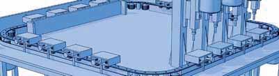

74 Multi-Motion-ine Mounting example Assembly line Multi-Motion-ine 72

75 C-ine System S
76 C-ine System S To be in a position to offer complete guide systems the C-ine consists of guide rails, guide rollers and carriages. Guide rails and rollers can be used as individual components; in most cases however, standard carriages are used. The following figure applies to the loads indicated in the tables below: The cold drawn rails have a C shape and are induction hardened. The rollers run on the inside raceways of the C-profile. The rails are zinc-plated; alternatively they are available with nickel-plated surface. ased on the different design of the rollers, constructions with fixed or floating bearings can be realised. Thereby errors in parallelism, height and angle can be balanced. Only one rail shape is necessary for this. Nadella offers 3 rail sizes. The carriages can be adjusted free of play. They are equipped with concentric and eccentric rollers and can be combined with 3, 4 or 5 rollers. MAX OAD ON INDIVIDUA CARRIAGES The tables below show the maximum load that can be applied to an individual carriage. Short carriage Essential technical properties: Guide Carriage Fy N Fz N Mx Nm My Nm Mz Nm Mzl Mzr steel rail, drawn, induction hardened zinc-plated rail, alternatively with nickel-plated surface rollers for fixed and floating bearing constructions high balance of mounting surface errors and misalignment high performance and rugged rollers lubricated for life dust resistant S 28 C3 RCS S 43 C3 RCS S 63 C3 RCS Fy with effect on the concentric rollers. ong carriage Guide Carriage Fy N Fz N Mx Nm My Nm Mz Nm Mzl Mzr easy fitting easy smooth running high speeds up to 8 m/s (depending on roller size and application) S 28 C3 RCS A C4 RCS C C4 RCS A C4 RCS C5 RCS A C5 RCS acceleration up to 50 m/s2 working temperatures up to 80 C possible pitch of rail borings standard or according to customer drawings S 43 C3 RCS A C4 RCS C C4 RCS A C4 RCS C5 RCS A C5 RCS integrated lubricating system at the front sides of the carriage Fy with effect on the concentric rollers. The max load is based on the guide roller values (load capacity of bolt and bearing) and on the max contact pressure of 1250N/mm2 between rail and roller. oads are rated for effect in direction Y exclusively or in direction Z exclusively. A combination of rates reduces the values. 74
77 C-ine System S DYNAMIC OAD CAPACITY OF THE INDIVIDUA CARRIAGE The following tables indicate the nominal load which corresponds to a nominal bearing lifetime of 100 km. ong carriage with 3 rollers C3 A view from above Short carriage Guide Carriage 10 = (Ci/Pi) 3 x 100 km Ci and Pi are the load capacity and the applied load for a certain load direction. Cy N Cz N CMx Nm CMy Nm CMz Nm Mzl Mzr S 28 C3 RCS S 43 C3 RCS S 63 C3 RCS Cy with effect on the concentric rollers. ong carriage with 4 rollers C4 C C4 A view from above view from above ong carriage Guide Carriage Cy N Cz N CMx Nm CMy Nm CMz Nm Mzl Mzr C4 view from above S 28 C3 RCS A C4 RCS C C4 RCS A C4 RCS C5 RCS A C5 RCS S 43 C3 RCS A C4 RCS C C4 RCS A C4 RCS C5 RCS A C5 RCS ong carriage with 5 rollers C5 A view from above Cy with effect on the concentric rollers. CARRIAGE CONFIGURATIONS In the following carriage configurations the dashed guide rollers ( ) are concentric and fixed, the plain guide roller ( ) are eccentric and can be set to preload the system. Short carriage with 3 rollers C5 view from above Typ C3 view from above The markings and show the contact points with the running surface of the rails. 75
78 C-ine System S Calculation example: platform with 4 carriages C3 RCS N The general arrangement is shown in the drawing below. Auto-aligning systems Self-aligning systems are used to balance high mounting surface tolerances between two parallel installed guides. The Nadella system S can be combined with the rollers RCS and RAS so that high horizontal or vertical tolerances can be balanced. The platform runs along the two rails and is charged with load F which takes effect 100 mm and 50 mm afar from the middle of the carriage. Data: guide S 43; carriage C3 RCS I x = 400 mm, I z = 300 mm F = 6000 N, X F = 100 mm, Z F = 50 mm In this configuration Py is the load on the mostly loaded carriage and is calculated as follows: F F X F F Z F P = + + = 2750 N 4 2 I X 2 I Z Horizontal adjustment Dx Fixed bearing: Carriages equipped with rollers type RCS/RCSR to compensate radial and axial loads. Floating bearing: Carriages equipped with rollers type RAS/RASR to compensate radial loads only. The load Fy indicated in the table of max load for carriage C3 RCS is 6000 N. Max. possible value: Dx = 1,5 mm The system nominal lifetime is calculated as follows: from the table of the dynamic load capacity, the value Cy for carriage C3 RCS is N. 10 = (13.200/2.750) 3 x 100 = km Important remark: The rail must be lubricated to reach this value. Otherwise the expected lifetime can be reduced by fretting between rail and roller. 76
79 C-ine System S Vertical adjustment Dy Fixed bearing: Carriages equipped with concentric rollers type RCS and eccentric rollers type RASR to compensate radial and axial loads. This allows for a tilting movement of the carriage up to the max. tilting angle. Floating bearing: Carriages equipped with concentric rollers type RAS and eccentric rollers type RASR to compensate axial loads only. The value Dy depends on the distance between the rails and the max. possible tilting angle α = ± 1.5 of the carriage at the fixed bearing side. Max inclined movement admissible for self-aligning tables and carriages Carriage C3 RAS28 C4 RAS28 C5 RAS28 C3 RAS43 C4 RAS43... C5 RAS43... α ax ( ) S (mm) H nominal (mm) Guide 1 0.5/ S / S 43 C3 RAS63 1 1/ S 63 C3 RYS28 C4 RYS28... C5 RYS28... C3 RYS43 C4 RYS43... C5 RYS S S 43 C3 RYS S 63 Carriages type...ras... only consist of guide rollers type RAS (concentric) and RASR (eccentric). Carriages type...rys... only consist of guide rollers type RCS (concentric) und RASR (eccentric). +S S Screw type DIN EN ISO 7380 (10.9) Guide Screw size d Torque wrench settings (Nm) S 28 M5 x S 43 M8 x S 63 M8 x
80 C-ine System S Hole pattern A: boring for counterbore screws according DIN EN ISO 7380 S 28 S 43 G H2 H g D H1 S 63 G H2 H g D H1 +1 l1-2 l +1-2 Hole pattern : boring for countersunk screws according DIN EN ISO 74 G 1 G 1 S 28 S 43 S 63 g 1 D 1 g 1 D 1 Dimensions (mm) Moment of inertia (cm 4 ) H H 1 H 2 D G g D 1 G 1 g 1 I I 1 J x J y S S S ) onger rails will be fitted with finish-machined joints. Weight (kg/m) (1) max (mm) Rail design standard - drawn, induction hardened raceways (MT) - surface zinc-plated (GZ) Surface options - chemically nickel-plated (NW) - uncoated blasted (no suffix) Fixing holes - hole pattern according to catalogue (A or ) - hole pattern according to drawing (NZ) - without holes (NF) Example standard type: S43MT2480AGZ Screws DIN EN ISO 7380 (10.9) are included in delivery. 78

81 C-ine Guide Rollers RCS concentric eccentric R SW 2 P M SW 1 k De d d 1 A m S min. l 1 concentric eccentric De R d 1 (1) d m S min. Dimensions (mm) P A l 1 M SW 1 SW 2 k Guide RCS 28 RCSR M S 28 RCS 43 RCSR M10 x S 43 RCS 63 RCSR M16 x S 63 Dynamic loads (N) imit loads (N) ife coefficients concentric eccentric Cw (3) radial F r axial F a X Y 1) Tolerance of mounting hole: H7 2) The tightening torques apply to non-lubricated threads; for lubricated threads the values have to be multiplied by ) Cw = load for lifetime of 100 km Torquewrench settings (Nm) 2) RCS 28 RCSR RCS 43 RCSR RCS 63 RCSR Weight (g) Guide rollers will be supplied with washers and nuts (DIN 439). Contact angle α for the load calculation: 55 Standard seals type RS 79
82 C-ine Guide Rollers RAS concentric eccentric R SW 2 P M SW 1 k De d d 1 m S min. A l 1 concentric eccentric De R d 1 (1) d m min. (4) m max. (4) Dimensions (mm) S min. P A l 1 M SW 1 SW 2 k Guide RAS 28 RASR M S 28 RAS 43 RASR M10 x S 43 RAS 63 RASR M16 x S 43 Dynamic load (N) imit load (N) Torque wrench settings (Nm) 2) concentric eccentric Cw (3) radiale F r RAS 28 RASR RAS 43 RASR RAS 63 RASR ) Tolerance of mounting hole: H7 2) The tightening torques apply to non-lubricated threads; for lubricated threads the values have to be multiplied by ) Cw = load for lifetime of 100 km 4) Maximum displacement of dimension m to ensure proper guide roller function and safety. Weight (g) Guide rollers will be supplied with washers and nuts (DIN 439). Contact angle α for the loadd calculation: 55 Standard seals type RS 80
83 C-ine Carriages C3 RCS, C3 RAS, C3 RYS 1 H 1 c l y G c G a D b H 2 H l x Dimensions (mm) 1 I x l y H H 1 H 2 G a b c k C3 RCS M5 (2x) S 28 short carriage C3 RCS M8 (2x) S 43 C3 RCS M8 (4x) S 63 Weight (kg) Guide Dimensions also apply to C3 RAS and C3 RYS. 1 c e G l y b l x Dimensions (mm) 1 I x l y H H 1 H 2 G b c e k long C3 RCS A M S 28 carriage C3 RCS A M S 43 Weight (kg) Guide Dimensions also apply to C3 RAS and C3 RYS. The markings show the contact points with the running surface of the rails. 81
84 C-ine Carriages C4 RCS, C4 RAS, C4 RYS Roller combinations The markings show the contact points with the running surface of the rails. C4 C C4 A C4 H 1 1 c e G l y b H 2 H l x Dimensions (mm) 1 I x l y H H 1 H 2 G b c e k Weight (kg) Guide C4 RCS C C4 RCS A C4 RCS C4 RCS C C4 RCS A C4 RCS M S M S 43 Dimensions also apply to C4 RAS C/A/ and C4 RYS C/A/. 82
85 C-ine Carriages C5 RCS, C5 RAS, C5 RYS Roller combinations The markings show the contact points with the running surface of the rails. C5 A C5 H 1 1 c e G l y b H 2 H l x Dimensions (mm) 1 I x l y H H 1 H 2 G b c e k Weight (kg) Guide C5 RCS A C5 RCS M S 28 C5 RCS A C5 RCS M S 43 Dimenisions also apply to C5 RAS A/ and C5 RYS A/. 83
86

87 ase-ine DC, C Systems
88 ase-ine DC system DC system is based on rails, guide rollers and carriages that provide a complete guiding system. Rails and rollers can be used as single elements. In most cases the application is based on standard carriages. The load capacities are tabulated with reference to the axis system showed in the sketch below: Rails Carriages T4 PFV DC T4 PFV T4 PFV DC T4 PFV T4 PFV DC T4 PFV T4 PFV DC T4 PFV Cy N Cz N CMx Nm CMy Nm CMz Nm Calculation example: carriage loaded with an external load F Carriage T4 PFV ; F = 2000 N. MAXIMUM OADS ON SINGE CARRIAGE Z The following table shows the maximum loads that can be applied on a single carriage. Rails Carriages T4 PFV DC T4 PFV T4 PFV DC T4 PFV T4 PFV DC T4 PFV T4 PFV DC T4 PFV Fy N Fz N Mx Nm The maximum loads are based on the stud and bearing strengths and on a maximum contact pressure, between rail and roller, of 1250 N/mm 2. The load in the table are considered as acting singularly. For applications with many loads acting at the same time the loads must be reduced. ASIC DYNAMIC OADS OF SINGE CARRIAGE The following table shows the nominal loads that correspond to a nominal life of the bearing at 100 km. The nominal lifetime of the carriage can be estimated from the standard bearing formula 10 = (Ci/Pi) 3 x 100 km My Nm Mz Nm Ci is the basic dynamic load capacity in a specific direction i and Pi is the external load applied in the same specific direction. The external load F acts in the z-axis direction: Pz = F = 2000 N In the table of the maximum loads you find that the load capacity Fz for carriage T4 PFV is equal to 3900 N, so the system is validated against breakage. To estimate the system lifetime we proceed as follows: from the table of the basic dynamic loads we see that Cz, for the carriage T4 PFV , is equal to 6100 N. The nominal lifetime will be: 10 = (6100/2000) 3 x 100 = 2837 km Important notes: - in order to reach the calculated lifetime it is important to lubricate the rails; - for load configurations with many loads and moments acting at the same time in different directions, please refer to the calculation examples you can find at the beginning of the catalogue or contact our Technical department. 86
89 ase-ine Guide rails DC DC and DC DC A g DC...S H E d H 1 D I l 1 DC...D l DC G D F l 1 l Dimensions (mm) Moments of inertia (2) (cm 4 ) Weight (kg/m) d I H H 1 A E D G g F l l 1 J x J y DC S (3) DC D (3) DC S (3) DC D (3) DC S DC D DC S (3) DC D (3) max length in single element =6000 (1) 1) onger rails are supplied in sections with ground butt joints and, on request, with pin connection 2) Inertia value based on equivalent aluminium yield N/mm 2 3) Available with stainless steel shafts Hole layout - holes according to catalogue (S) - finishes to drawing (NZ) - without holes (NF) Optional features - ground one end (R) - ground both ends ( RR ) - stainless steel shafts (NX) - chromium plated shafts (CH) Example of standard designation : DC2595S 2010 S NX See page 17 for standard codification 87
90 ase-ine Guide rails C 1 l 1 l G g H d H 1 F D Dimensions (mm) Moments of inertia (2) (cm 4 ) Weight (kg/m) d 1 H H 1 D G g F l l 1 J x J y C 10 (3) C C C 30 (3) max length in single element =6000 (1) 1) onger rails are supplied in sections with ground butt joints and, on request, with pin connection 2) Inertia value based on equivalent aluminium yield N/mm 2 3) Available with stainless steel shafts Hole layout - holes according to catalogue (S) - finishes to drawing (NZ) - without holes (NF) Optional features - ground one end (R) - ground both ends ( RR ) - stainless steel shafts (NX) - chromium plated shafts (CH) Example of standard designation : C S See page 17 for standard codification 88
 PFVR 35.16 (3) PFV 35.18 (3) PFVR 35.18 (3) PFV 43.22 (3) PFVR 43.22 (3) PFV 50.25 (3) PFVR 50.25 (3) Dimensions (mm) De d d (1) 1 d T m S min. P A I 1 M SW 1 25 10 8 M8x1.25 15.5 7.5 11 9 34.")
91 ase-ine Guide rollers PFV with gothic arch profile concentric eccentric d P SW 2 M SW 1 T SW 1 k De d d 1 m S min. A l 1 concentric PFV (3) PFV (3) PFV eccentric PFVR (3) PFVR (3) PFV (3) PFVR (3) PFV (3) PFVR (3) PFV (3) PFVR (3) Dimensions (mm) De d d (1) 1 d T m S min. P A I 1 M SW M8x M10x M10x M12x M14x PFVR M16x SW k Recommended pairings C 10/DC DC C 18/DC C 22 DC C 30 Dynamic load (N) imit loads (N) ife coefficients C w (4) radial F r axial F a X Y Torque wrench (2) settings (Nm) Weight (g) PFV PFVR PFV PFVR PFV PFVR PFV PFVR PFV PFVR PFV PFVR ) Housing bore tolerance: H7 2) The torque wrench settings are given for non-lubricated threads; for lubricated threads, multiply figure by 0.8 3) Available in stainless steel (suffix NX) 4) Cw basic load for 100 km 5) The guide rollers are complete with self-locking washers and hexagonal nut (DIN 439) for fitting 6) Pressure angle for load calculation: 60 7) NR seals, RS type 89

92 ase-ine Guide rollers RKO concentric eccentric d-h7 SW 2 P M SW 1 T SW 1 k=1 De d d1 m S min. A I1 Dimensions (mm) concentric eccentric De d-h7 d (1) 1 d T m S min. P A I 1 M SW 1 SW 2 RKO RKOR M 20 x RKO RKOR M 20 x RKO RKOR M 20 x RKO RKOR M 30 x k Dynamic load (N) imit loads (N) ife coefficients C w (4) radial F r axial F a X Y Torque wrench (Nm) (2) settings Weight (kg) RKO RKOR RKO RKOR RKO RKOR RKO RKOR ) Housing bore tolerance: H7 2) Torque wrench settings are given for non-lubricated threads; for lubricated threads, multiply figure by 0.8 3) Standard seals: material NR, type RS 4) On request, the guide rollers can be supplied with Viton seals for operating temperatures up to 120 C (suffix V) 5) Cw basic load for 100 km 6) The guide rollers is complete with self-locking washers and hexagonal nut for fitting 7) Pressure angle α for load calculation: 70 C 90
 120 120 165 85 85 41 28 20.5 M8 15 0.96 DC 10.54 T4PFV 35 16 165 (1) 165 126 126 50.5 36 24 M8 15 2.1 DC 16.80 T4PFV 35 16 250 (1) 250 165 211 126 50.5 36 24 M8 15 3.1 DC 16.80 T4PFV 35 18 150 (1) 150 150 113 113 49 36 24 M8 15 1.")
93 ase-ine Carriages T4PFV H = = H 2 = b b I y = G I x H 1 I x I y Dimensions (mm) H H 1 H 2 G b Weight (kg) Recommended pairings T4PFV (1) M DC T4PFV (1) M DC T4PFV (1) M DC T4PFV (1) M DC T4PFV (1) M DC T4PFV (1) M DC T4PFV (1) M DC T4PFV (1) M DC ) Available with stainless steel guide rollers (NX) 2) Carriages are complete with guide rollers 3) Pressure angle for load calculation: 60 91

94 ase-ine Wiper NAID G E d A C S d Dimensions (mm) E C A G A S Recommended pairings NAID 010 NAID 016 NAID 018 NAID 022 NAID 025 NAID C 10 DC C 18/DC C 22 DC C 30 92
 U F m d A C P Vf Vr 32.5 15.5 30 30.5 16.")
95 ase-ine ubricator UC guide roller mounting rollers plate UC M3x12 M4 10 PFV UC M3x12 M4 15 PFV UC M3x12 M4 15 PFV UC M4x12 M5 30 PFV UC UC X Dimensions (mm) U F m d A C P Vf Vr M4x12 M M4x12 M5 Weight (g) Suggested combinations PFV PFV ) The lubricator is supplied with the felt already lubricated. The lubricant has a mineral oil base 2) At the mounting, insert the screws inside the rollers plate, without tighten them, adjust the height of the plastic part in order to put it in contact with the raceways and then block it 3) The screws Vf for the frontal mounting are included in the packaging. Arrange two thread holes for dimension Vf in the mounting rollers plate 4) The screw for the mounting on the nut side of the roller are not included in the packaging. Arrange on the mounting rollers plate the holes in order to insert the screws Vr Optional features - felt without lubricant (D) 93


96 ase-ine Mounting examples Oxy fuel cutting machine ase-ine C and DC 94


97 ase-ine FWS, FWH System
98 ase-ine Guide rails FWS X g b m c d M E Dimensions (mm) d X M g E b m c FWS M FWS M FWS M FWS M single guide element =4500 (1) for 2 screw channels Distance (mm) Screw distance max. Torque wrench settings (Nm) for additional holes (NZ) Distance (mm) J x Moments of inertia (2) cm 4 J y Weight (kg/m) FWS FWS FWS FWS ) onger rails are supplied in sections with ground butt joints at the rods 2) Inertia value based on equivalent aluminium yield N/mm 2 including shafts Hole layout - finishes to drawing (NZ) - without holes (NF) Optional features - ground one end (R) - ground both ends ( RR ) - stainless steel shafts (NX) Example of standard designation : FWS32/1500 NF See page 17 for standard codification 96
99 ase-ine Guide rails FWH a g 0,2 b d m c M E Dimensions (mm) d a M g E b m c FWH M FWH M FWH M FWH M Maximum length of single guide element = (1) Distance (mm) for 1 screw channels Screw distance max. Torque wrench settings (Nm) for additional holes Distance (mm) J x Moments of inertia (2) cm 4 J y Weight (kg/m) FWH FWH FWH FWH ) onger rails are supplied in sections with ground butt joints 2) Inertia value based on equivalent aluminium yield N/mm 2 including shafts Hole layout - finishes to drawing (NZ) - without holes (NF) Optional features - ground one end (R) - ground both ends ( RR ) - stainless steel shafts (NX) Example of standard designation : FWH32/1500 NF See page 17 for standard codification 97
100 ase-ine Guide rollers FR..EU concentric eccentric 80 M SW 2 k P SW 3 SW 1 De d d 1 T m S min. A l 1 The sides of the race are slightly convex Dimensions (mm) concentric eccentric De d (1) 1 d T m S min P A I 1 M SW 1 SW 2 SW 3 k FR 22 EU (4) FRR 22 EU (4) 22 9 M 6 x FR 32 EU (4) FRR 32 EU (4) M 10 x FR 40 EU (4) FRR 40 EU (4) M 12 x FR 52 EU FRR 52 EU M 16 x Dynamic load (N) imit loads (N) ife coefficients C w (4) radial F r axial F a X Y Torque wrench settings (2) (Nm) Weight (g) FR 22 EU FRR 22 EU FR 32 EU FRR 32 EU FR 40 EU FRR 40 EU FR 52 EU FRR 52 EU ) Housing bore tolerance: H7 2) The torque wrench settings are given for non-lubricated threads; for lubricated threads, multiply figure by 0.8 3) Cw basic load for 100 km 4) FR/R 22, 32, 40 are available in stainless steel (NX) The guide rollers are complete with self-locking washers and hexagonal nut (DIN439) for fitting Pressure angle α for load calculation: 40 NR seals RS type 98
 concentric eccentric De d1 (1) d (2) T m A l 1 l h M SW G o Q Ig")
101 ase-ine Guide Rollers FR..EU AS, FR..EU AZ AS concentric 80 SW eccentric k d 1 Q De T d d 1 M s m l 1 A l m o AZ 80 SW G k De T d d 1 M m o m l 1 h A l lg Dimensions (mm) concentric eccentric De d1 (1) d (2) T m A l 1 l h M SW G o Q Ig (6) s k FR 22 EU AS (5) FRR 22 EU AS (5) 22 6 M FR 32 EU AS (5) FRR 32 EU AS (5) 32 9 M (4) 0.5 FR 40 EU AS (5) FRR 40 EU AS (5) M (4) 1 FR 52 EU AS FRR 52 EU AS M (4) 1.5 FR 22 EU AZ (5) FRR 22 EU AZ (5) FR 32 EU AZ (5) FRR 32 EU AZ (5) FR 40 EU AZ (5) FRR 40 EU AZ (5) FR 52 EU AZ FRR 52 EU AZ Guide roller size Dynamic load (N) imit loads (N) ife coefficients Weight AS (g) Weight AZ (g) On re quest for AZ screw DIN7984 Cw (3) radial F r axial F a X Y M 5 x M 8 x M10 x M14 x 60 1) Housing bore tolerance: H7 2) Safety threads SPIRAOCK 3) Cw basic load for 100 km 4) Guide roller with washers DIN134 without screw DIN7984 or DIN912 5) FR/R 22, 32, 40 AS and AZ are available in stainless steel (NX) 6) AZ: minimum length of the thread engaged steel = 1 x d cast iron = 1.25 x d aluminium = 2 x d AS screws length: min = d+o+s; max = m+4+o+s NR seals RS type Pressure angle α for load calculation: 40 99
102 ase-ine Floating guide rollers FR..EU concentric eccentric 80 X M SW 2 n k P SW 3 SW 1 De d d 1 T m S min. A l 1 The race ways are slightly convex Dimensions (mm) concentric eccentric De d 1) 1 d T m S min P A l 1 M n X SW 1 SW 2 SW 3 k FR 22 EU 5) FRR 22 EU 5) 22 9 M6 x FR 32 EU 5) FRR 32 EU 5) M10 x FR 40 EU 5) FRR 40 EU 5) M12 x FR 52 EU FRR 52 EU M16 x FR 62 EU FRR 62 EU M20 x Dynamic load (N) imit load (N) imit load Inox version (N) NX C w 4) radial F r radial F r Torque wrench setting 2) (Nm) FR 22 EU FRR 22 EU FR 32 EU FRR 32 EU FR 40 EU FRR 40 EU FR 52 EU FRR 52 EU FR 62 EU FRR 62 EU Weight (g) 1) Housing bore tollerance: H7 2) The torque wrench settings are given for non-lubricated threads; for lubricated threads multiply figure by 0.8 3) Weight without fittings 4) Cw = asic load for 100 Km 5) Dimensions for stainless steel (NX) version Standard seals: material NR, RS type Guide rollers include self-locking washers and hexagonal nut (DIN 439) Pressure angle α for load calculation:

103 ase-ine Carriage T4FR = = H H 1 b = = b G I y I x H2 T4FR T4FR Dimensions (mm) T4FR M T4FR M T4FR T4FR T4FR T4FR I x I y H H 1 H G M6 M60 M8 M80 M10 M10 b Weight (kg) 0.6 FWS Suggested combinations FWS 22 FWS 32 FWS 32 FWS 40 FWS 40 FWS 52 FWS
104 ase-ine Guide Rollers combination I y I h Y Y Roller type FR/FRR..EU, FR/FRR..EU AS, FR/FRR..EU AZ, FRK, FRR, FR Y I y I h FWS 22 FWH FWS 32 FWH FWS 40 FWH FWS 52 FWH Mounting Examples Glue dispensing machine 102
105 Flexi-ine 645 FWN System
106 Flexi-ine 645 System Flexi-ine 645 Aluminium guide rails FWN as well as carriages TA4 and T4 are the components of this line. In addition to the standard dimensions that are ISO 645 compatible, the guide system can be adapted to customers requirements. ore holes and threads on the guide rails can be made in any distance required, the carriages may have overlengths and a special hole pattern and all this is also available as corrosion resistance type NX. Compared to linear guides made of steel these guide rails and carriages weigh up to 45% less and stand out due to their excellent running performance which minimises the driving power and reduces significantly the cost for motors and controls. With eccentric bolts the guide rollers of the carriages are kept free from play. However the user also has the possibility to change the settings, for example in case of vibrations, and to apply an individual preload on the guide system. On both sides of the carriages can be mounted end plates with oil-soaked felt seals to ensure low-wear operation. The following graph applies to the loads indicated in the tables: MAXIMUM OAD ON INDIVIDUA CARRIAGES The table below shows the maximum load that can be applied to an individual carriage. Carriage Fy (N) Fz (N) Mx (Nm) My (Nm) Mz (Nm) TA4GA17.06 T4GA17.06 TA4GA19.06 T4GA DYNAMIC OAD OF THE INDIVIDUA CARRIAGE The table below shows the load corresponding to the nominal working life of 100 km. The nominal working life of the carriage can be determined by the standard bearing formula. 10 = (Ci/Pi) 3 x 100 km Ci is the carrying capacity in a specific direction and Pi is the load applied in the same direction. Carriage Cy (N) Cz (N) CMx (Nm) CMy (Nm) CMz (Nm) TA4GA17.06 T4GA17.06 TA4GA19.06 T4GA Important: in the calculation examples at the beginning of the catalogue. In case of questions our application engineers will be pleased to assist you. 104
 FWN 20 6 20 18 10 5.5 M6 12 13.5 7 30 60 1.3 FWN 25 6 23 21 11 6.6 M6 12 18 8.5 25.5 30 60 1.")
107 Flexi-ine 645 Guide rails FWN Dimensions according to DIN 645 D oring layout A X d d l1 l m b t E g G oring layout l1 l Dimensions (mm) d E X D d G g m t b 19.5 l 1 l Weight (kg/m) FWN M FWN M Max length of single guide element =5 800 mm (1) 1) onger rails are supplied in sections with ground butt-joints Hole layout - holes according to DIN (A or ) - finishes to drawing (NZ) - without holes (NF) Optional features - ground one end (R) - ground both ends (RR) - stainless steel shafts (NX) Example of standard designation : FWN20/1000 A See page 17 for standard codification 105
 0.3 FWN 20 F z Max load on a single carriage M z Carriage F y (N) F z (N) M x (Nm) M y (Nm) M z (Nm) TA4GA 17.")
108 Flexi-ine 645 Carriage TA4 Dimensions according to DIN 645 H H 1 g e y G e x TA4GA Dimensions (mm) G H H 1 e x e y g 63 M Suggested combinations TA4GA M FWN 25 onger carriages on request Weight (kg) 0.3 FWN 20 F z Max load on a single carriage M z Carriage F y (N) F z (N) M x (Nm) M y (Nm) M z (Nm) TA4GA TA4GA M y F y M x Optional features - available with stainless steel guide rollers (NX) - available with felts for lubrication (UU) 106
 0.25 FWN 20 F z Max load on a single carriage M z Carriage F y (N) F z (N) M x (Nm) M y (Nm) M z (Nm) T4GA 17.")
109 Flexi-ine 645 Carriage T4 Dimensions according to DIN 645 H H 1 g e y G e x T4GA Dimensions (mm) G H H 1 e x e y g Suggested combinations T4GA FWN 25 onger carriages on request Weight (kg) 0.25 FWN 20 F z Max load on a single carriage M z Carriage F y (N) F z (N) M x (Nm) M y (Nm) M z (Nm) T4GA T4GA M y F y M x Optional features - available with stainless steel guide rollers (NX) - available with felts for lubrication (UU) 107


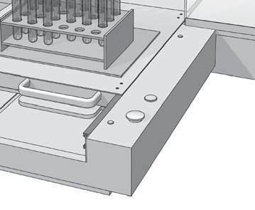
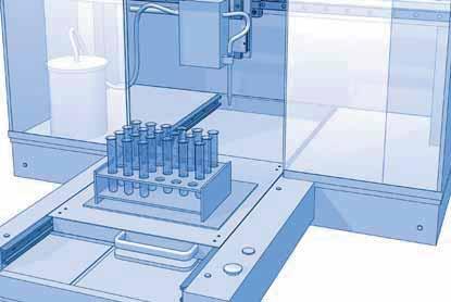


110 Flexi-ine 645 Mounting examples Medical equipment Flexi-ine 108

111 U-ine M, M System
112 U-ine M system M system is based on rail, guide rollers and carriages to provide a complete guiding system. Guide rails and rollers can be used as single elements. In most cases the application is based on standard carriages and cursors. Referring to the axis system below, the load capacities are tabulated as follows: My MAX OAD ON SINGE CARRIAGE The following table shows the maximum load that can be applied on a single carriage. Guide Carriage M 30 C3 RC C4 RC M 40 C3 RC C4 RC M 65 C3 RC C4 RC * Fy directed to load the two concentric guide rollers Y Fy N 1000* * * 4160 M 90 C4 RC M 120 T4 RC T4 RC T4 RCP T4 RCP M 180 T4 PFV T4 PFV Fz N The maximum load is based on the guide roller data (stud and bearing strength) and on maximum contact pressure between rail and roller of 1250 N/mm 2. oading is considered to be acting in a single plane or axis only. ASIC DYNAMIC OAD OF SINGE CARRIAGE The following table shows the nominal load that corresponds to a nominal life of the bearing at 100 km. The nominal carriage life can be estimated from the standard bearing formula. Ci and Pi are the basic capacity and load applied for a specific direction. Mz Mx 10 = (Ci/Pi)^3 x 100 km Z Mx Nm 3,5 7 7, X My Nm 5, Mz Nm Guide Carriage M 30 C3 RC C4 RC M 40 C3 RC C4 RC M 65 C3 RC C4 RC M 180 T4 PFV T4 PFV * Fy directed to load the two concentric guide rollers Calculation example: four carriages C3RC platform The common configuration is shown in the here following sketch: Y Cz N The platform moves along the two guide rails and has a load of F acting at 100 mm and 50 mm from the carriage centre. Data: guide M 65 and carriages C3RC I x = 400 mm I z = 300 mm F = N X F = 100 mm Z F = 50 mm Cy N 3000* * * M 90 C4 RC M 120 T4 RC T4 RC T4 RCP T4 RCP In this configuration the load on the most heavily loaded carriage is Py and can be calculated using the following formula: F F X F F Z F P = + + = 2750 N x z The load Fy shown in the max loads table is 4.160N (carriages mounted with eccentric roller on top), so the system is validated against breakage. To estimate the system life we proceed as follows: from the nominal life table Cy = N 10 = (15.800/2.750)^3 x 100 = km Important note: to reach this value it is important to lubricate the rail, otherwise fretting corrosion between rail and roller can reduce the expected life. F CMx Nm Z CMy Nm X CMz Nm
113 U-ine Auto-aligning system Systems Auto-aligning systems are assembled with guide rollers RA type on M system carriages tables. The guide rollers RA type allows axial displacement of the roller on the pin. An O ring retains the roller in position during the mounting. Auto-aligning systems compensate for opposite rail misalignment errors. They are useful for mounting inaccurately aligned structures or those structures subject to flexure. Dx C3RA C4RA T4RA Is used to compensate for Dx misalignment between opposite rails. The table or carriage with all guide rollers RA/RAR type can move towards or away from the rail. RA provides radial support only. Axial load, transverse to the direction of travel, is reacted by carriage type RC on the opposite rail. α C3RY C4RY T4RY Rail misalignment Dy requires the ability for both carriages to rotate. The table or carriage RY type, with guide rollers RC/RCP in contact with a steel shaft of the M rail and guide rollers RAR type in contact with the opposite shaft, allows carriage rotation ensuring at the same time the transverse direction control. The maximum Dy value is dependent on the distance between the rails and the tabulated maximum angle α for that carriage. Note: RY carriage axial load capability is lower than the same size RC/RCP carriage....rc......ry... Dy...RA......RA... Max transverse moving allowed by auto-aligning tables and carriages ±α Carriage code (1) max ( ) S max (mm) H nominal (mm) Rail C3RA C4RA C3RY C4RY M 30 C3RA C4RA C3RY C4RY M 40 C3RA C3RY C4RA C4RY C4RA C4RY M 65 M 90 H ± s T4RA T4RA T4RY T4RY T4RA T4RA T4RY T4RY M 120 1) See light load systems Nadella catalogue for table and carriage dimensions. 2) Variations of dimension H exceeding ± s can compromise bearing axial moving and decrease the roller limit load, Fr. 111
 (cm 4 ) J x J y Weight (kg/m) (1) max (mm) M 30 (4) 6 21.5 32 15.5 10.5 6 11 4.5 9.5 2.5 16 80 40 0.5 3 1.1 6 000 M 40 (4) 6 29 42 20 14 8 14 4.")
114 U-ine Guide rails M M 30 H 2 d l G H 2 d l M 90 H 1 H H 1 H g D g M 40 M 65 H 2 d l G H 1 H H 2 g d l H 1 H M 120 g D G M 180 l P H H 1 H 2 d M D (3) G (3) D a e a g l 1 l d I H Dimensions (mm) H 1 H 2 M D G g a e P l l 1 Moments of inertia (2) (cm 4 ) J x J y Weight (kg/m) (1) max (mm) M 30 (4) M 40 (4) M 65 (4)) M 90 (4)) M 120 (4) M (3) 20.1 (3) ) onger rails are supplied in sections with ground butt joints and, on request, with pin connection 2) Inertia value based on equivalent aluminium yield N/mm 2 3) Slot for nut DIN 508 4) available with stainless steel shafts (suffix NX) Hole layout - holes according to catalogue (S) - finishes to drawing (NZ) - without holes (NF) Optional features - ground one end (R) - ground both ends ( RR ) - chromium plated shafts (CH) - stainless steel shafts (NX) Example of standard designation : M 40/1720 NF See page 17 for standard codification 112
 conc. d 1 (1) ecc. d Y m Dimensions (mm) S min.")
115 U-ine Guide rollers RC, RCP, PFV RC/RCP M SW 2 SW 1 PFV M SW 2 SW 1 De d De d m S min. concentric m S min. concentric d d P P Y SW 1 k Y SW 1 k d 1 d 1 A A l 1 eccentric l 1 eccentric concentric eccentric De d d 1 (1) conc. d 1 (1) ecc. d Y m Dimensions (mm) S min. P A l 1 M SW 1 SW 2 k Suggested combination RC (3) RCR (3) M 5x M 30 RC (3) RCR (3) M 8x M 40 RCR (3) M10x M 65 RCP RCPR (3) RC (3) M12x M 120 PFV (3) PFVR (3) M12x M 180 Dynamic load (N) imit loads (N) ife coefficients Pa/Pr 0.37 Pa/Pr > 0.37 C w (4) radial Fr axial F a X Y X Y Torque wrench (2) settings (Nm) Weight (g) RC RCR RC RCR RC RCR RCP RCPR PFV PFVR ) Housing bore tolerance: H7 2) The torque wrench settings are given for non-lubricated threads; for lubricated threads, multiply figure by 0.8 3) Available in stainless steel (suffix NX) with RS seals type 4) Cw basic load for 100 km 5) The guide rollers are complete with self-locking washers and hexagonal nut (DIN 439) for fitting 6) Pressure angle for load calculation: 60 7) Standard shields ZZ type for RC and RCP; NR seals type RS for PFV 113
116 U-ine Guide rollers RA concentric eccentric d P X SW 2 d 1 SW 1 Y M De d k SW 1 (size 35 and 42 only) m S min A l 1 concentric eccentric De d d 1 (1) conc. d 1 (1) ecc. d Y m Dimensions (mm) S min. P A X (5) l 1 M SW 1 SW 2 k Suggested combination RA 17.06(6) RAR 17.06(6) M 5x M 30 RA 24.06(6) RAR 24.06(6) M 8x M 40 RA 35.10(6) RAR 35.10(6) M10x M 65 RA RAR M12x M 120 Dynamic load (N) C w (3) imit loads (N) (5) radial F r Torque wrench (2) settings (Nm) Weight (g) RA RAR RA RAR RA 3510 RAR RA RAR ) Housing bore tolerance: H7 2) The torque wrench settings are given for non-lubricated threads; for lubricated threads, multiply figure by 0.8 3) Cw basic load for 100 km 4)The guide rollers are complete with self-locking washers and hexagonal nut for fitting 5) Dimension ± X is the max displacement from dimension m to ensure proper guide roller function and safety 6) Available in stainless steel (suffix NX) with RS seals type 7) Standard shields ZZ type 114
 imit loads (N) ife coefficients Pa/Pr 0.37 Pa/Pr > 0.")
117 U-ine Guide wheels GA A d Y De Di (1) De d Di (1) Dimensions (mm) Y A GA (4) GA (4) GA (4) GA GA GA GA Dynamic load (N) imit loads (N) ife coefficients Pa/Pr 0.37 Pa/Pr > 0.37 C (2) w radial C or axial C oa X Y X Y Weight (g) GA GA GA GA GA GA GA ) Tolerance of Diameter Di: +0 / mm 2) Cw basic load for 100 km 3) Pressure angle for load calculation: 60 4) Available in stainless steel (suffix NX) with RS seals type 5) Standard shields ZZ type (GA with RS seals type) 115
118 U-ine Carriage C3RC, C3RA, C3RY e H 1 u G G g I y b k c l x H 2 H I x I y H H 1 Dimensions (mm) H 2 G g b c u e k Weight (kg) Suggested combinations C3RC M M 30 C3RC M M 40 C3RC M M 65 1) Dimensions in the table are correct also for carriages C3 RA, C3 RY 2) Available with stainless steel guide rollers (suffix NX) Carriage C4RC, C4RA, C4RY G e G H 1 u g I y b k c I x H H 2 I x I y H H 1 Dimensions (mm) H 2 G g b c u e k Weight (kg) Suggested combinations C4RC M M 30 C4RC M M 40 C4RC M M 65 C4RC M M 90 1) Dimensions in the table are correct also for carriages C4 RA and C4 RY 2) Available with stainless steel guide rollers (suffix NX) 116

119 U-ine Carriage T4RC, T4RCP, T4PFV, T4RA, T4RY T4RC T4RCP T4PFV b G H H 2 = = b H H 2 b I y = b I y = G I x H 1 I x H 1 I x I y Dimensions (mm) H H 1 H 2 G b Weight (kg) Recommended pairing T4RC M M 120 T4RC M M 120 T4RCP M M 120 T4RCP M M 120 T4PFV M M 180 T4PFV M M 180 1) Dimensions valid also for T4RA and T4RY ubricator UM H C 2) G S symmetry axis of the rail A E D T S U UM.. CS UM.. CD UM.. CS UM.. CD UM 040 CD/CS UM 065 CD/CS A Dimensions (mm) UM U E T H 7 13 C C3 RC C4 RC Suggested combinations with the rails 1) The lubricator is supplied with the felt already lubricated. The lubricant has a mineral oil base - 2) One lubricator for packaging. Countersunk head screws for the mounting are already in the packaging - 3)The lubricator can be mounted on carriages RC, RA and RY - (4) Optional felt without lubricant (D) G M2.5 M3 M4 S M 30 M 40 M
120 U-ine System M Application Aluminium guide rails M as well as RC guide rollers with a plastic-coated outer ring are the components of this line. M can be used whenever extremely compact dimensions, simple linear motion and an economic solution are required. M system is suitable for manual and low precision movements, for safety doors, for the adjustment of cameras and sensors and many other products. Applications can be found amongst others in mechanical engineering, medical and food engineering or object monitoring. My Y Mz Z Mx X Materials, surfaces, running characteristics The guide rail, made of extruded aluminium, has a hard anodised surface. This grey-coloured protective coating ensures a significant protection against wear and corrosion. In addition, it has good tribological characteristics. The guide rollers are made of corrosion-resistant bearing steel and their outer rings are coated with a special polyamide material. This material combination contributes to a further improvement of the already known good running characteristics of Nadella roller guides and makes possible an absolutely low-noise linear motion without any stick-slip. In contrast to steel to steel combinations, the plastic coating of the guide rollers is slightly flexible and allows higher production tolerances and thus a costefficient production. oad rating and working life The carrying capacity of the system is determined by the surface pressure between the plastic coating and the aluminium guide rail. The working life is not calculated. The following graph applies to the loads indicated in the tables: MAXIMUM OAD ON INDIVIDUA CARRIAGES The table below shows the maximum static load that can be applied to an individual carriage for up to 100 hours without leading to permanent deformation of the outer rings. For short stress (<2s) and under dynamic load the values can be doubled. Carriage Fy (N) * Fy with effect on the two concentric rollers. Option sliding guide Fz (N) Mx (Ncm) My (Ncm) Mz (Ncm) C3RC 16 NX 150* C4RC 16 NX For mostly static applications such as adjusting devices or for non-critical linear movements a suitable polyamide slide with incorporated lubricant is available. Please contact our application engineers. 118
121 U-ine Guide Rails M H G H 2 H 1 Hole layout - holes according to catalogue (S) - holes according to drawing (NZ) - without holes (NF) g D l 1 l Dimensions (mm) Moments of inertia (1) (cm 4 ) H H1 H2 D G g I I1 Jx Jy Weight (kg/m) max (mm) M ) Inertia value based on E module for aluminium N/mm². Surface hard anodised Carriage C3RC 16 NX G e H 1 l y b Carriage C4RC 16 NX l x H H 2 G e l y b l x Dimensions (mm) Ix Iy H H1 H2 G b e Weight (g) C3RC 16 NX M C4RC 16 NX M Corrosion-resistant design Example: standard rail M20/1200S standard carriage C3RC16NX 119


122 U-ine Mounting example Protective doors on machine tool U-ine 120
123 Product index (in alphabetic order) Product Description Page Carriage with burnished body for the ROOC system 43 C Rail composed by an aluminium body and one shaft in steel, with a single raceway for ase-ine system 88 C3RA, C4RA C3RAS, C4RAS, C5RAS Carriages with body in anodised aluminium with 3 or 4 guide rollers type RA for auto-aligning system U-ine Carriage with body in anodised aluminium with 3, 4 or 5 guide rollers type RAS for auto-aligning system C-ine C3RC, C4RC Carriage with body in anodised aluminium with 3 or 4 guide rollers type RC for U-ine system C3RCS, C4RCS, C5RCS C3RY, C4RY C3RYS, C4RYS, C5RYS Carriages with body in anodised aluminium with 3, 4 or 5 guide rollers type RCS for auto-aligning system C-ine Carriage with body in anodised aluminium with 3 or 4 guide rollers type RC and RA for auto-aligning system U-ine Carriages with body in anodised aluminium with 3, 4 or 5 guide rollers type RCS and RAS for auto-aligning system C-ine DC Rail composed by an aluminium body and two shafts in steel, with two raceways for ase-ine system 87 DIST FS Spacers for rails FS, FSH and FSR 59 FK Guide wheel with tapered roller bearings for GP rails of Heavy-ine system 31 FKU Guide wheel with tapered roller bearings for GU rails of Heavy-ine system 22 FKX Guide wheel with tapered roller bearings for FSX rails of V-ine system 56 FKY Guide wheel with tapered roller bearings for FS and FSH rails of V-ine system 56 FR..EU FR..EU AS/AZ Guide roller with ball bearings for FS and FSH rails of V-ine system, and FWS and FWH rails of ase-ine system Floating guide rollers with ball bearings for FS and FSH rails of V-ine system, and FWS and FWH rails of ase-ine system FR..EU Floating guide rollers with needle roller bearings for FS and FSH rails of V-ine system, and FWS and FWH rails of ase-ine system FRN..EI Guide roller with needle roller bearings for FS and FSH rails of V-ine system 54 FS..M, FSH..M Rail in steel with ground raceways, for V-ine system FS..MT, FSH..MT Rail in steel with sandblasted raceways, for V-ine system FSR..M Circular rail in steel, for Multi-Motion-ine system 67 FSRO Oval circuit composed of linear and circular pieces of rail for Multi-Motion-ine system 69 FSRQ Ring circuit composed of linear and circular pieces of rail for Multi-Motion-ine system 70 FSX..M Rail in steel with ground raceways, for V-ine system 51 FSX..MT Rail in steel with sandblasted raceways, for V-ine system 50 FWH Rail composed by an aluminium body and one shaft in steel, with a single raceway for ase-ine system 97 FWN Rail composed by an aluminium body and two shafts in steel, with two raceways for Flexy-ine 645 system 105 FWS Rail composed by an aluminium body and two shafts in steel, with two raceways for ase-ine system 96 GC Guide roller with needle roller bearings for GP rails of Heavy-ine system GA Guide wheel with double row of balls with oblique contact, with gothic arch profile for U-ine system 115 GP..M Rail in steel, ground raceways for Heavy-ine system 29 GP..MC Rail in steel, rough ground raceways for Heavy-ine system 28 GU..M Rail in steel, ground raceways for Heavy-ine and Rolbloc system GU..MT Rail in steel, sandblasted raceways for Heavy-ine and Rolbloc system M Rail composed by an aluminium body and two shafts in steel, with two internal raceways for U-line system 112 M Rail totally in aluminium with two internal raceways for U-line system 119 S Rail in steel with internal raceways for C-ine system 78 UC ubricator for ase-ine system (guide rollers running on C and DC rails) 93 UM ubricator for U-ine system (carriages running in M rails) 117 UP ubricator for Heavy-ine system (guide rollers running on GP rails) 36 UU ubricator for Heavy-ine system (guide rollers running on GU rails) 24 UX, UY ubricator for V-ine system (guide rollers running on FS and FSH rails) M Carriage with black anodised aluminium body and three guide rollers with ball bearings, for Rolbloc system 42 NAID Wipers for C and DC rails of ase-ine system
124 Product index (in alphabetic order) Product Description Page PFV gothic profile Guide roller with gothic arch profile, based on ball bearings, for C and DC rails of ase-ine system, and M rails of U-ine system PK Guide roller with tapered roller bearings for GP rails of Heavy-ine system 30 PR Adjustment plates for carriages of Rolbloc system 44 RA Floating guide rollers with gothic arch profile, with a double row of balls with oblique contact, for M rails of U-ine system 114 RAS Floating guide rollers with balls for S rails of C-ine system 80 RC Guide rollers with gothic arch profile, with a double row of balls with oblique contact, for M rails of U-ine system 113 RCP Guide rollers with balls for S rails of C-ine system 113 RCS Guide rollers with balls profile, for S rails of C-ine system 79 RKO Guide rollers with tapered roller bearings, with gothic arch profile for C and DC rails of ase-ine system 90 RKU Guide rollers with tapered roller bearings, for GU rails of Heavy-ine system 21 RKU Floating guide rollers with tapared roller bearings for GU rails of heavy line system 23 RKX Guide rollers with tapered roller bearings, for FSX rails of V-ine system 55 RKY Guide rollers with tapered roller bearings, for FS and FSH rails of V-ine system 55 RKY, RKX Floating guide rollers with tapared roller bearings for FS.. rails of V-ine system 58 SAG Guide pins for the mounting alignment of GU rails of Heavy-ine system 25 TA4, T4 Carriages with anodised aluminium body with four guide rollers type GA for FWN rails of Flexi-ine system T4FR Carriages with anodised aluminium body with four guide rollers type FR..EI for FWS rails ase-ine system 101 T4PFV Carriages with anodised aluminium body with four guide rollers type PFV with gothic arch profile for C and DC rails of ase-ine system, and M rails of U-ine system 91 T4R Steering carriage for FSR..M circular rails of Multi-Motion-ine system 71 T4RA T4RC, T4RCP T4RY Carriages with black anodised aluminium body with four floating guide rollers type RA with gothic arch profile for M rails of U-ine system Carriages with black anodised aluminium body with four guide rollers type RC or RCP with gothic arch profile for M rails of U-ine system Carriages with black anodised aluminium body with four guide rollers type RC/RCP and RA with gothic arch profile for M rails of U-ine system Suffix index (in alphabetic order) A AC CH D GZ M MC MT NF NX NW NZ R RR S UU V Standard hole pattern according to the catalogue for GP rails Hollow shafts optional for rails C, DC and M Standard hole pattern according to the catalogue for GP rails Chromium plated shafts Felt without lubricant Surface zinc-plated for S rails (C-ine) Ground profile Rough ground profile (for GP rails) Drawn and sandblasted profile Rails without holes Stainless steel version for guide rollers or guide rails Chemical Nickel-plating Finishes to drawing Ground on one end Ground on both ends Standard hole pattern according to the catalogue Felts for lubrication available (for carriages TA4 and T4 of Flexi-ine 645 system) Seals in Viton 122
125 Note
126 Note
127 3D CAD DRAWINGS Our 2D and 3D drawings can be down loaded from our web site:


 764 0806")


128 Nadella S.r.l. Via Melette, Milano Tel Fax Nadella GmbH Rudolf-Diesel-Straße Nufringen Tel. +49 (0) Fax +49 (0) Nadella Inc Hawkins Road Jackson, MI USA Toll Free Fax +1 (517) info@nadella.com Nadella Office Shanghai 728 German Centre, 88 Keyuan Road Pudong Shanghai Tel Tel info@nadella.cn.com NADEA WORDWIDE ORGANISATION Europe: Austria Czech Republic Denmark Finland France Germany Hungary Italy Netherlands Norway Poland Romania Slovakia Slovenia Spain Sweden Switzerland Turkey United Kingdom USA Corea China Taiwan India Singapore rasil Head offiche ranches and distributors 2013 NADEA Printed in Italy
Technical features. Nadella linear systems. Steel guides. Guides
 Nadella linear systems With this line of products, NADELLA confirms the aim to provide manufacturing solutions tailored to the user s needs in order to achieve simple automation at a low cost. The process
Heavy-Line. GU System
 GU ystem Guide rails GU..M, GU..MT GU...MT 90 ± 0' G H c h g sm b + 0,05 D I I GU...M 90 ± 5' L 0,02 H c h b + 0,05 0, 0,02 The longitudinal slot, made with + 0.05 tolerance, permits using reference elements
Base-Line. DC, C Systems
 DC, C Systems DC system DC system is based on rails, guide rollers and carriages that provide a complete guiding system. Rails and rollers can be used as single elements. In most cases the application
TELESCOPIC-LINE. Semi-telescopic-rail LST. Telescopic-rail LSE. Linear guides with ball-cage LSS
 TELESCOPIC-LINE Semi-telescopic-rail LST Telescopic-rail LSE Linear guides with ball-cage LSS 1 Ball rails LSS, LST and LSE The ball rails produced by Nadella are very compact and flexible products. Made
Base-Line. FWS, FWH System
 FWS, FWH Syste Guide rails FWS X g c d E Diensions () d X g E c FWS 22 6 34 5 16 36 14 FWS 32 8 42 6 45 25 17 FWS 40 54 8 24 57 30 19 14 FWS 52 66 32 69 36 24 18 single guide eleent =4500 (1) for 2 screw
TELESCOPIC RAILS HARDENED TELESCOPIC RAILS FOR HIGHLY DYNAMIC APPLICATIONS 7.1 PRODUCT OVERVIEW 7.2 PART EXTENSIONS 7.
 7 TELESCOPIC RAILS HARDENED TELESCOPIC RAILS FOR HIGHLY DYNAMIC APPLICATIONS PAGE 106 PAGE 116 PAGE 120 PAGE 126 7.1 PRODUCT OVERVIEW 7.2 PART EXTENSIONS 7.3 FULL EXTENSIONS 7.4 LINEAR GUIDES 105 PRODUCT
...components in motion. Easy Rail
 ...components in motion Easy Rail Easy Rail Introduction The Easy Rail family have a compact cross-section and low-friction movement. Robust and Long Service Life Easy Rail s range of cross-sectional rail
Easy Slide Rails ov -easy_slide_divider - U pdated
 Easy Slide Rails ov-easy_slide_divider - Updated - 18-09-2017 163 Easy Slide Rails Easy Slide Rails Introduction The Easy Slide family of linear rails have a compact cross-section and low-friction movement.
Courtesy of CMA/Flodyne/Hydradyne Motion Control Hydraulic Pneumatic Electrical Mechanical (800)
") 01_1 Miniature st Headline_36 Ball Rail pt/14.4 Systems mm second line 2 Linear Motion and Assembly Technologies Miniature Ball Rail Systems Ball Rail Systems Roller Rail Systems Linear Bushings and Shafts
01_1 Miniature st Headline_36 Ball Rail pt/14.4 Systems mm second line 2 Linear Motion and Assembly Technologies Miniature Ball Rail Systems Ball Rail Systems Roller Rail Systems Linear Bushings and Shafts
Inner block. Grease nipple. Fig.1 Structure of LM Guide Actuator Model KR
 LM Guide ctuator Model LM Guide + all Screw = Integral-structure ctuator Stopper Housing all screw Inner block Grease nipple Outer rail earing (supported side) Housing Stopper Double-row ball circuit earing
Miniature Ball Rail Systems
 R310EN 2210 (2004.06) The Drive & Control Company 2 Bosch Rexroth AG Linear Motion and Assembly Technologies Miniature-BRS R310EN 2210 (2004.06) Linear Motion Systems Ball Rail System Standard Ball Rail
TELESCOPIC RAIL HEAVY
 TELESCOPIC RAIL HEAVY Every care has been taken to ensure the accuracy of the information contained in this catalogue, but no liability can be accepted for any errors or omissions. We reserve the right
1. Product overview Basic-Line-Module AXN Product description Basic-Line-Module AXN 4-5. Guide system Roller guide 6 Drive system Gear belt 7
 Directory Page 1. Product overview Basic-Line-Module AXN 3 2. Product description Basic-Line-Module AXN 4-5 Guide system Roller guide 6 Drive system Gear belt 7 3. Basic-Line-Modul AXN 45-Z 8-9 AXN 65-Z
Profi le rail guides LLR
 Profi le rail guides LLR Content The SKF brand now stands for more than ever before, and means more to you as a valued customer. While SKF maintains its leadership as the hallmark of quality bearings throughout
Any reproduction, even partial, is allowed only by written permission by Rollco.
 EASYSLIDE Every care has been taken to ensure the accuracy of the information contained in this catalogue, but no liability can be accepted for any errors or omissions. We reserve the right to make changes
Ball Rail Systems RE / The Drive & Control Company
 Ball Rail Systems RE 82 202/2002-12 The Drive & Control Company Rexroth Linear Motion Technology Ball Rail Systems Roller Rail Systems Standard Ball Rail Systems Super Ball Rail Systems Ball Rail Systems
R310EN 2211 ( ) The Drive & Control Company
 The Drive & Control Company") eline Ball Rail Systems R310EN 2211 (2006.04) The Drive & Control Company Bosch Rexroth AG Linear Motion and Assembly Technologies Ball Rail Systems Roller Rail Systems Linear Bushings and Shafts Ball
eline Ball Rail Systems R310EN 2211 (2006.04) The Drive & Control Company Bosch Rexroth AG Linear Motion and Assembly Technologies Ball Rail Systems Roller Rail Systems Linear Bushings and Shafts Ball
Ball. Ball cage. Fig.1 Structure of Caged Ball LM Guide Actuator Model SKR
 Caged all LM Guide Actuator Model Inner block all screw shaft Grease nipple Outer rail all cage all Structure and Features Fig.1 Structure of Caged all LM Guide Actuator Model Caged all LM Guide Actuator
TRANSLATION (OR LINEAR)
") 5) Load Bearing Mechanisms Load bearing mechanisms are the structural backbone of any linear / rotary motion system, and are a critical consideration. This section will introduce most of the more common
5) Load Bearing Mechanisms Load bearing mechanisms are the structural backbone of any linear / rotary motion system, and are a critical consideration. This section will introduce most of the more common
Dynamic Elements Linear Slides Mechanical Drive Elements Accessories for Mechanical Drive Elements
 8 Dynamic Elements Mechanical Drive Elements Accessories for Mechanical Drive Elements The Dynamic Elements product group of the MB Building Kit System contains components which enable precise linear movement.
114 NOSE SEIKO CO.,LTD NOSE SEIKO CO.,LTD
 114 NOSE SEIKO CO.,LTD NOSE SEIKO CO.,LTD 115 and Part Code Applicable axis diameter Feature Part Code 5 ~ 3 General purpose cam follower with screwdriver groove on the stud head. Available with stainless
4 Self aligning ball bearings
 Rolling bearings 4 Self aligning ball bearings Designs and variants... 538 Basic design bearings... 539 Bearings with an extended inner ring.. 540 Cages... 540 Sealing solutions... 540 Greases for sealed
R310EN 2302 ( ) The Drive & Control Company
 The Drive & Control Company") R31EN 232 (26.4) The Drive & Control Company Bosch Rexroth AG Linear Motion and Assembly Technologies Ball Rail Systems Linear Bushings and Shafts Ball Screw Drives Linear Motion Systems Basic Mechanical
R31EN 232 (26.4) The Drive & Control Company Bosch Rexroth AG Linear Motion and Assembly Technologies Ball Rail Systems Linear Bushings and Shafts Ball Screw Drives Linear Motion Systems Basic Mechanical
DS 0002 MOV 2014 DISTITEC Srl
 DS 0002 MOV 2014 DISTITEC Srl The realization of this catalog occurred in tighter control of data contained therein. Due to the ongoing technical evolution of our products, we reserve the right to make
Crossed Roller Ways. Description of each series and Table of dimensions. Anti-Creep Cage Crossed Roller Way
 Crossed Roller Ways Description of each series and Table of dimensions Crossed Roller Way Page - to -7 Anti-Creep Cage Crossed Roller Way Page - to - Crossed Roller Way Unit Page - to - In the table of
INDEX EASY RAIL: THE SOLUTION IS EASY...D4 EXAMPLES OF LOAD CAPACITIES...D5 ORDER CODES...D6 MOUNTING EXAMPLES...D7 TECHNICAL DATA...
 INDEX EASY RAIL: THE SOLUTION IS EASY...D4 EXAMPLES OF LOAD CAPACITIES...D5 ORDER CODES...D6 MOUNTING EXAMPLES...D7 TECHNICAL DATA...D8 STANDARD CONFIGURATIONS...D10 VERIFICATION UNDER STATIC LOAD...D12
506E. LM Guide Actuator General Catalog
 LM Guide Actuator General Catalog A LM Guide Actuator General Catalog A Product Descriptions 506E Caged Ball LM Guide Actuator Model SKR.. A2-4 Structure and Features... A2-4 Caged Ball Technology... A2-6
10 Thrust ball bearings
 10 Thrust ball bearings Designs and variants.............. 1010 Single direction thrust ball bearings... 1010 Double direction thrust ball bearings.. 1010 Cages............................ 1010 Bearings
LINEAR BEARINGS & HOUSINGS
 LINEAR BEARINGS & HOUSINGS www.euro-bearings.com Tel. 01908 511733 email: sales@euro-bearings.com GENERAL INFORMATION Introduction Ball bushings are anti-friction bearings for linear motion. They offer
Axial-radial cylindrical roller bearings
 Axial-radial cylindrical roller bearings Designs and variants.............. 320 Bearing data..................... 321 (Boundary dimensions, tolerances) Product table 5.1 Axial-radial cylindrical roller
...components in motion. Miniature Linear Guideways
 ...components in motion Miniature Linear Introduction Miniature linear guideway systems are widely used throughout industry for precise, compact applications. Precise and Stainless The gothic arch shape
LM Guide Actuator KR. For details, visit THK at CATALOG No E. Product information is updated regularly on the THK website.
 LM Guide Actuator KR For details, visit THK at www.thk.com Product information is updated regularly on the THK website. CATALOG No.209-10E Integrated LM Guide and all Screw High-rigidity / High-precision
X-Rail FrontespizioXRai.indd 1 07/10/ :30:14
 X-Rail 1 Product explanation Product explanation X-Rail: orrosion resistant or zinc-plated steel linear bearings ig. 1 X-Rail is the product family of roller embossed guide rails for applications in which
Contents. Page. 1. Product description. 2. The AXC line of linear axes. 3. AXLT line of linear tables. AXC and AXS product overview...
 SNR Industry Contents Page 3 1. Product description AXC and AXS product overview... 6-8 Dynamic load ratings of the linear motion systems... 9 Compact modules... 10-11 Linear tables... 12 Telescopic axes...
Linear Guideways ov -linear -guidew ays-divider - U pdated
 Linear Guideways ov-linear-guideways-divider - Updated - 11-01-2017 163 Linear Guideways Linear Guideways Introduction L1016 Linear guideways Linear guideways are widely used throughout industry for heavy-duty
Linear Bushings and Shafts. The Drive & Control Company
 Linear Bushings and s The Drive & Control Company 2 Bosch Rexroth Corp. Linear Motion and Assembly Technologies Linear Bushings R310A 3100 Linear Motion Technology Ball Rail Systems Standard Ball Rail
NEW LAN SERIES RAILS THE COST-EFFECTIVE REVOLUTION IN LINEAR MOTION COST-EFFECTIVE MOVING YOUR IDEAS LINEAR AND TELESCOPIC MOTION TECHNOLOGY
 NEW LAN SERIES RAILS THE COST-EFFECTIVE REVOLUTION IN LINEAR MOTION COST-EFFECTIVE MOVING YOUR IDEAS LINEAR AND TELESCOPIC MOTION TECHNOLOGY COST-EFFECTIVE REVOLUTION IN LINEAR MOTION 2 NEW PATENTED T
Any reproduction, even partial, is allowed only by written permission by Rollco.
 LINEAR UNIT E-SMART Every care has been taken to ensure the accuracy of the information contained in this catalogue, but no liability can be accepted for any errors or omissions. We reserve the right to
eline Ball Screw Assemblies
 eline Ball Screw Assemblies R310EN 3314 (2005.06) The Drive & Control Company R310EN 3314 (2005.06) Bosch Rexroth AG 3 Product Overview 4 Technical Data 6 with Screw-in Single Nut ZEV-E-S Single fixed
TECHNICAL INFORMATION
 General Nomenclature Spherical Roller Bearings The spherical roller bearing is a combination radial and thrust bearing designed for taking misalignment under load When loads are heavy, alignment of housings
SIT-LOCK self locking elements
 self locking elements Advantages of on the shaft-hub connection compared with traditional systems Easy assembly and disassembly Both actions take place by locking and unlocking the clamping screws with
Profile rail guides LLT
 Profile rail guides LLT Contents The SKF brand now stands for more than ever before, and means more to you as a valued customer. While SKF maintains its leadership as the hallmark of quality bearings throughout
Precision Modules PSK
 Precision Modules PSK The Drive & Control Company Rexroth Linear Motion Technology Ball Rail Systems Roller Rail Systems Standard Ball Rail Systems Super Ball Rail Systems Ball Rail Systems with Aluminum
14 Track runner bearings
 14 Track runner bearings Designs and variants............... 1100 Cam rollers... 1100 Single row cam rollers............. 1100 Double row cam rollers............ 1100 Support rollers... 1101 Support rollers
V SWISS MADE LINEAR TECHNOLOGY
 Excerpt from main catalogue inear modules V 11-15 SWISS MDE INER TECHNOOGY ine Tech inear modules Table of contents Product overview 6 7 Design fundamentals / ubrication / Maintenance 8 Profile cross-sections
NEEDLE ROLLERS. Polígono Indutrial O Rebullón s/n Mos - España -
 NEEDLE ROLLERS Needle rollers In certain applications, the limited amount of space available for bearings and the loads to be supported require the use of a full complement of needles independent of any
Ball screw drives KGT General technical data
 KGT General technical data Manufacturing process The thread profile is produced by cold rolling in the thread rolling method. Both screw and nut have a gothic thread profile. The load angle is 45. Linear
Linear Drive with Ball Screw Drive Series OSP-E..SB
 Linear Drive with Ball Screw Drive Series OSP-E..SB Contents Description Data Sheet No. Page Overview 1.30.001E 47-50 Technical Data 1.30.002E-1 to 5 51-55 Dimensions 1.30.002E-6, -7 56-57 Order instructions
Caged Ball LM Guide Actuator SKR
 Caged Ball LM Guide Actuator SKR For details, visit THK at www.thk.com Product information is updated regularly on the THK website. CATALOG No.309-11E Integrated LM Guide and Ball Screw High-rigidity /
for flex design of MOTION GUIDE Journal Bearing
 MOTION GUIDE for flex design of Motion Guide Systems provide the maintenance-free and smooth running of V-shaped rolling bearings fitted on both sides of flat rail. Various combinations of components are
with MR rail and R, R.T, R.S sliders
 inear Roller earing ystem with MR rail and R, R.T, R. sliders N R R R N The MR eries inear Rail ystem consists of a -section steel rail with internal convex raceways, where robust double row ball bearing
Main Catalogue. EichenbergerGewinde. 100 % Swiss made
 EichenbergerGewinde 100 % Swiss made Main Catalogue Carry ball screws Carry Speed-line high-helix ball screws Speedy high-helix lead screws Rondo round thread lead screws The choice is yours Thread rolling
series Linear guideways CG-serie 3.3 CG series
 series CG-serie 3.3 CG series 3.3.1 Properties of the linear guideways, series CG The HIWIN linear guideways of the CG series with O-arrangement of the ball tracks guarantee high torque loading capacity,
Cylindrical roller bearings
 Cylindrical roller bearings Cylindrical roller bearings are manufactured in a various range of constructive types and sizes, particularly single row cylindrical roller bearings but also two or more row
Linear Bushings and Shafts Inch Series
 Industrial Hydraulics Electric Drives and Controls Linear Motion and Assembly Technologies Pneumatics Service Automation Mobile Hydraulics Linear Bushings and s Inch Series The Drive and Control Company
Linear Bushings and Shafts
 Linear Bushings and s R310EN 3100 (2004.09) The Drive & Control Company R310EN 3100 (2004.09) Linear Bushings Bosch Rexroth AG 3 Linear Bushings and s Selection Guide 9 Product Overview 10 Overall Dimensions
LINEAR ROLLER SYSTEM with MR rail and R, R.T, R.S sliders
 NR R R N NR ROR YTM with MR rail and R, R.T, R. sliders The MR eries inear Rail ystem consists of a -section steel rail with internal convex raceways, where robust double row ball bearing rollers travel.
CYLINDRICAL ROLLER BEARING CATALOG TIMKEN THRUST AND PLAIN BEARINGS CATALOG
 CYLINDRICL ROLLER BERING CTLOG TIMKEN THRUST ND PLIN BERINGS CTLOG Spherical Plain Bearings SPHERICL PLIN Overview: Timken s spherical plain bearings consist of a spherically ground inner ring housed in
Slotted nut NMG. Housing nut GWR. Bosch Rexroth AG. for economical constructions. a min. 0,3. M A = tightening torque of slotted nut.
 R310EN 3301 (2009.08) Precision Ball Screw Assemblies Bosch Rexroth AG 113 Slotted nut NMG for economical constructions B D d d1 b M A = tightening torque of slotted nut a min. 0,3 Polyamide insert Designation
Track Rollers/ Cam Followers
 Track Rollers/ Cam Followers Page Nomenclature...................................... 460 Introduction....................................... 462 Identification....................................... 462
Guide units. For toolmaking, fixture manufacturing and machine engineering
 Guide units For toolmaking, fixture manufacturing and machine engineering Guide units in compliance with DIN, ISO and STEINEL standards or according to your specifications Guide pillars Guide and pillar
Linear Drive with Toothed Belt and Integrated Guide with Recirculating Ball Bearing Guide with Roller Guide Series OSP-E..BHD
 Linear Drive with and Integrated Guide with Recirculating Ball Bearing Guide with Roller Guide Contents Description Page Overview 11-14 Version with Recirculating Ball Bearing Guide Technical Data 15-17
Q&A Session for Advanced Linear Bearings and Guides 201 : Troubleshooting for Design Engineers
 Q&A Session for Advanced Linear Bearings and Guides 201 : Troubleshooting for Design Engineers Date: April 22, 2009 Q: We are currently looking into using Self Lubricating Bushings in a high-load Off-
HepcoMotion MHD Heavy Duty Track Roller Guidance System
 Motion Without Limits HepcoMotion MHD Heavy Duty Track Roller Guidance System product overview The HepcoMotion MHD system provides an accurate, durable and low friction linear guide which is particularly
carriages to carry the load (taking into account any moment loads). Unlike the N series sliders these CS sliders do not have protective side seals.
. Unlike the N series sliders these CS sliders do not have protective side seals.") Light Duty Sliders, size 18 no side seal, front fixing Long Linear s L1918.CS Material Zinc plated steel body. Steel rollers (100Cr6) with metal (2Z) or rubber (2RS) seals. Technical notes To be used with
Light Duty Sliders, size 18 no side seal, front fixing Long Linear s L1918.CS Material Zinc plated steel body. Steel rollers (100Cr6) with metal (2Z) or rubber (2RS) seals. Technical notes To be used with
MINIRAIL Profiled miniature guideway
 MINIRAIL Profiled miniature guideway Table of Contents 1 Product overview and technical informations MINIRAIL a range of high-precision products.... 2 MINIRAIL overview accuracy classes:.... 3 MINIRAIL
PK couplings. Product description. PK couplings
 Product description The INKOMA-PK coupling is machine component designed to transmit torque between axially parallel, radially offset shafts. The coupling permits both static and dynamic stepless adjustment
Product description. PK couplings
 Product description The INKOMA-PK coupling is machine component designed to transmit torque between axially parallel, radially offset shafts. The coupling permits both static and dynamic stepless adjustment
LM Guide HCR/HMG. R Guide / Straight-Curved Guide Achieving a Simplified Mechanism. For details, visit THK at CATALOG No.
 LM Guide HCR/HMG R Guide / Straight-Curved Guide Achieving a Simplified Mechanism For details, visit THK at www.thk.com Product information is updated regularly on the THK website., CATALOG No.306-8E HCR
PRECISION BELLOWS COUPLINGS
 PRECISION BELLOWS COUPLINGS Bellows couplings are used where precise rotation, high speeds, and dynamic motion must be transmitted. They exhibit zero backlash and a high level of torsional stiffness, offering
Ball Screw Assemblies eline. The Drive & Control Company
 Ball Screw Assemblies eline The Drive & Control Company 2 Bosch Rexroth Corp. Linear Motion and Assembly Technologies eline BSA R310A 3314 (2005.04) Linear Motion Technology Ball Rail Systems Standard
Features of the LM Guide
 Features of the Functions Required for Linear Guide Surface Large permissible load Highly rigid in all directions High positioning repeatability Running accuracy can be obtained easily High accuracy can
Precision Modules PSK
 Precision Modules PSK 2 Bosch Rexroth AG Precision Modules PSK R999000500 (2015-12) Identification system for short product names Short product name Example:: P S K - 050 - N N - 1 System = Precision Module
FUNCTION OF A BEARING
 Bearing FUNCTION OF A BEARING The main function of a rotating shaft is to transmit power from one end of the line to the other. It needs a good support to ensure stability and frictionless rotation. The
Assembled Double Edge Ring System
 ssembled Double Edge Ring System The epcootion double edge ring system with carriage may be used in either complete ring form or with segments. t can also be combined with straight slides to form a track
Linear Drive with Toothed Belt Series OSP-E..B. Contents Description Overview Technical Data Dimensions Order Instructions 46
 Linear Drive with Toothed Belt Contents Description Page Overview 35-38 Technical Data 39-43 Dimensions 44-45 Order Instructions 46 35 The System Concept ELECTRIC LINEAR DRIVE FOR POINT-TO-POINT APPLICATIONS
Ball splines can be configured for an endless number of automated operations. Demystifying Ball Spline Specs
 Ball splines can be configured for an endless number of automated operations. Demystifying Ball Spline Specs Place a recirculating-ball bushing on a shaft and what do you get? Frictionless movement of
Bearing retention and clearances
 Bearing retention and clearances Bearing retention 9 Radial retention 9 Axial retention 91 Positioning of single bearing assemblies 91 Positioning of two bearing assemblies 92 Axial retention processes
The Separator arrangements depend on the application (see order example or separator options).
.") SLE Energy chains individual solutions large dimensions simple handling The order for a steel chain SLE should contain the following data: Type / Radius x Length / Width - Connector Arrangement ; Separator
SLE Energy chains individual solutions large dimensions simple handling The order for a steel chain SLE should contain the following data: Type / Radius x Length / Width - Connector Arrangement ; Separator
Chapter 11 Rolling Contact Bearings
 Chapter 11 Rolling Contact Bearings 1 2 Chapter Outline Bearing Types Bearing Life Bearing Load Life at Rated Reliability Bearing Survival: Reliability versus Life Relating Load, Life, and Reliability
Compact Modules. with ball screw drive and toothed belt drive R310EN 2602 ( ) The Drive & Control Company
 The Drive & Control Company") with ball screw drive and toothed belt drive R310EN 2602 (2007.02) The Drive & Control Company Bosch Rexroth AG Linear Motion and Assembly Technologies Ball Rail Systems Roller Rail Systems Linear Bushings
with ball screw drive and toothed belt drive R310EN 2602 (2007.02) The Drive & Control Company Bosch Rexroth AG Linear Motion and Assembly Technologies Ball Rail Systems Roller Rail Systems Linear Bushings
Uniline System FrontespizioUnilineSystem.indd 1 22/11/ :32:41
 Uniline ystem 1 Uniline series Uniline series Uniline series description ig. 1 Uniline is a family of ready-to-install linear actuators. They consist of internal ompact Rail roller sliders and steel-reinforced
V SWISS MADE LINEAR TECHNOLOGY
 Compact units Excerpt from main catalogue SWISS MADE LINEAR TECHNOLOGY V 11-15 Line Tech compact units Table of contents Product overview 106 107 Design fundamentals / Lubrication / Maintenance 108 Profile
Linear Actuator with Toothed Belt and Integrated Roller Guide Series OSP-E..BHD
 inear Actuator with Toothed Belt and Integrated Roller Guide Series OSP-E..BHD Contents Description Data Sheet No. Page Overview 1.15.001E 11-14 Technical Data 1.15.002E-1 to 3 15-17 Dimensions 1.15.002E-4
PERFORMANCE AND KNOW-HOW
 PRODUCT PROGRAM PERFORMANCE AND KNOW-HOW The NADELLA Group is today an absolute specialist for mechanical motion technology, offering you numerous products, the appropriate know-how and service for this
POSI-LOCK. Connects the Shaft and Hub with the Wedging Action of the Tapered Surface. Mechanical Shaft Lock ETP BUSHINGS
 Mechanical Shaft ock POSI-OCK Mechanical Shaft ock POSI-OCK Application Machine tool, pump, molding machine, printing machine, palletizing robot, various jigs and tools Connects the Shaft and Hub with
LA rails with. R.S series sliders. PA. series sliders ,5 37,2 24,3 28,20 18,30 14,8 18,2 28,2 28,6
 Monorace RN 18 MR rails with R. series sliders. 37 24 16,5 MR rails with R.T series sliders. 37,2 24,3 18 MR rails with R. series sliders.,20 18,30 14,8 M rails with R series sliders. M rails with R. series
Linear Actuator with Toothed Belt Series OSP-E..B
 Linear Actuator with Toothed Belt Series OSP-E..B Contents Description Data Sheet No. Page Overview 1.20.001E 21-24 Technical Data 1.20.002E-1 to 5 25-29 Dimensions 1.20.002E-6 30 Order Instructions 1.20.002E-7
KTR Torque Limiters Overload Protection Systems
 KT Torque Limiters Overload Protection Systems UFLEX - Friction Disk - Zero Backlash Ball Detent KT SI - Ball/oller Bearing Style KT SI Compact - Zero Backlash Ball Detent Catalog Contents (Metric) Page
Drawn cup needle roller bearings
 Drawn cup needle roller bearings Sealed drawn cup needle roller bearings... 78 Full complement drawn cup needle roller bearings... 79 3 Dimensions... 79 Tolerances... 79 Misalignment... 80 Cages... 80
...components in motion. Curviline Rail
 ...components in motion Curviline Curviline Introduction The Curviline rail system offers a cost-effective solution to curvi-linear applications. Flexibility when you need it Constant radius, variable
LM76 Linear Motion Bearings
 LM76 Linear Motion Bearings ROLLER BEARING PILLOW BLOCKS PDF FILE PDF FILE INDEX PAGE ADVANTAGES 1 DIMENSIONAL TABLES Single Pillow Blocks (SPB) 2 Double Pillow Blocks (DPB) 2 Twin Pillow Blocks (TWN)
Precision Modules PSK. The Drive & Control Company
 Precision Modules PSK The Drive & Control Company 2 Bosch Rexroth Coporation Precision Modules PSK R310A 2414 (2008.07) Linear Motion and Assembly Technologies Ball Rail Systems Roller Rail Systems Linear
Heavy-Duty Rod Ends - Male with integral spherical plain bearing
 Heavy-Duty Rod Ends - Male with integral spherical plain bearing 65700 Order No. Thread (hand) d 1 l 1 d 2 d 3 d 4 l 2 l 3 X g H7 65700.W0005 Right 5 33 M 5 11,11 18 20 9 14 65700.W0006 Right 6 36 M 6
FLEXIBLE COUPLINGS - RIGID COUPLINGS Up to Nm of torque and 205 mm bores
 Edition 10/2014 www.comintec.it FLEXIBLE COUPLINGS - RIGID COUPLINGS Up to 130.000 Nm of torque and 205 mm bores (BACKLASH FREE) Technology for Safety FLEXIBLE COUPLINGS - RIGID COUPLINGS (BACKLASH FREE):
FAG Cylindrical Roller Bearings full complement Standards Basic designs Tolerances Bearing clearance
 FAG Cylindrical Roller earings full complement FAG Cylindrical Roller earings full complement Standards asic designs Tolerances earing clearance Full complement cylindrical roller bearings are suitable
A superior alternative to hydraulic or pneumatic motion providing 15 times the life of a ball screw. Planetary Roller Screws
 A superior alternative to hydraulic or pneumatic motion providing 15 times the life of a ball screw Planetary Roller Screws Exlar Your Linear Motion Experts Exlar Corporation is committed to providing
Linear Actuator with Ball Screw Series OSP-E..S. Contents Description Overview Technical Data Dimensions 89
 Linear Actuator with Ball Screw Series OSP-E..S Contents Description Page Overview 79-82 Technical Data 83-88 Dimensions 89 79 The System Concept ELECTRIC LINEAR ACTUATOR FOR HIGH ACCURACY APPLICATIONS
LINEAR ACTUATORS. Courtesy of Steven Engineering, Inc. - (800)
") LINEAR ACTUATORS Pre-assembled, all-in-one linear actuators save design and installation time. Choose from NSK's two product lines: MonocarrierTM and ToughcarrierTM. Courtesy of Steven Engineering, Inc.
LINEAR ACTUATORS Pre-assembled, all-in-one linear actuators save design and installation time. Choose from NSK's two product lines: MonocarrierTM and ToughcarrierTM. Courtesy of Steven Engineering, Inc.
EMC-HD. C 01_2 Subheadline_15pt/7.2mm
 C Electromechanical 01_1 Headline_36pt/14.4mm Cylinder EMC-HD C 01_2 Subheadline_15pt/7.2mm 2 Elektromechanischer Zylinder EMC-HD Short product name Example: EMC 085 HD 1 System = ElectroMechanical Cylinder