NEW LAN SERIES RAILS THE COST-EFFECTIVE REVOLUTION IN LINEAR MOTION COST-EFFECTIVE MOVING YOUR IDEAS LINEAR AND TELESCOPIC MOTION TECHNOLOGY
|
|
|
- Candice Tucker
- 5 years ago
- Views:
Transcription

1 NEW LAN SERIES RAILS THE COST-EFFECTIVE REVOLUTION IN LINEAR MOTION COST-EFFECTIVE MOVING YOUR IDEAS LINEAR AND TELESCOPIC MOTION TECHNOLOGY

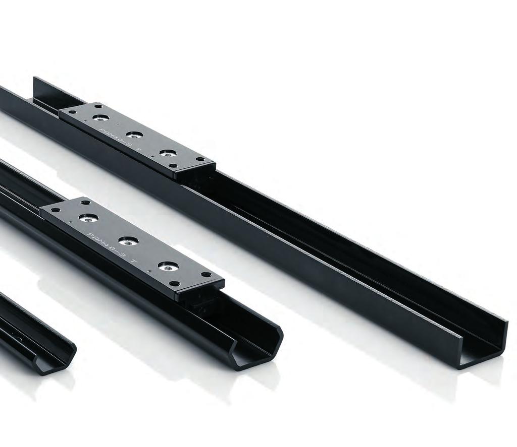
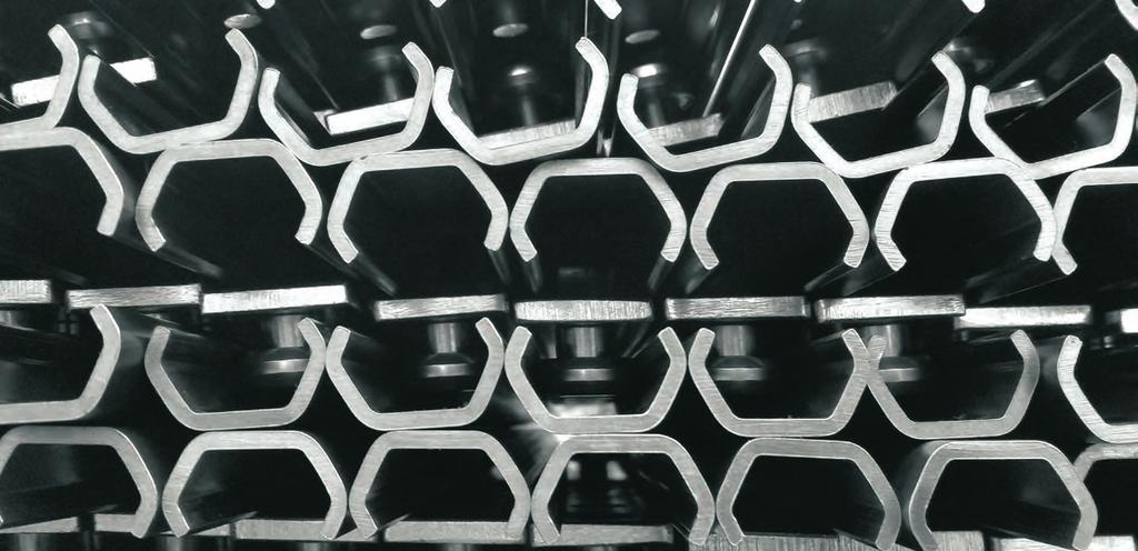
2 COST-EFFECTIVE REVOLUTION IN LINEAR MOTION 2 NEW PATENTED T RACE-NOX THERMOCHEMICAL CASE HARDENING AND BLACK OXIDISING TREATMENT MAXIMUM COMPACTNESS Compact C section rails in a range of sizes, with protected internal rollers. BLACK FINISH Elegant, top quality, black finish obtained by coating-free thermochemical treatment. Flame and abrasion resistant. Does not flake off like zinc plating and other deposited treatments. OPTIMUM LUBRICATION Extended, maintenance-free lifetime thanks to wipers with slow release felt lubricating pads that deposit a thin film of oil on the raceways. MAXIMUM STRENGTH Fully nitrided and black oxidised rails for excellent wear resistance and effective protection against corrosion. SMOOTH SLIDING Superbly smooth sliding, thanks to optimal preload adjustment of the eccentric rollers and good lubrication provided by the wipers with incorporated felt, impregnated with lubricant. SELF-ALIGNING SYSTEM Can be used in conjunction with LUN U section rails to create a self-aligning two-slide motion system capable of compensating for installation alignment errors.
3 COST-EFFECTIVE PERFORMANCE AND DURABILITY 3

4 TECHNICAL DESCRIPTION LAN rails are made from sheet steel and shaped by high precision, ultra-smooth forming rollers. They are then case hardened using our revolutionary TRACE-NOX nitriding and black oxidising process to ensure an extended lifetime and excellent corrosion resistance. TECHNICAL DESCRIPTION The slider bodies are cataphoretically blackened for maximum corrosion resistance. The rollers are made from core tempered and precision ground, bearing grade steel. The ball bearings are lubricated for life with wide temperature range bearing grease and protected by 2Z rated metal shields. Robust elastomer raceway wipers are fitted at both ends of the slider to protect the rollers and keep the raceways clean. The wipers incorporate oil-impregnated felt pads to keep the points of contact between raceway and roller properly lubricated, even for the lifetime of the rail. Wipers are held in place by a simple clip and can be removed and replaced easily. 4 LAN AND LUN SERIES RAILS GUIDING AND FLOATING LINEAR MOTION SOLUTIONS CONFIGURATIONS Sliders are available in 3 and 5-roller configurations. In 3-roller versions, the two lateral rollers run on the same raceway while the central roller runs on the opposite raceway. The lateral rollers are fixed, concentric rollers, while the central roller has an eccentric pivot for preload adjustment. In 5-roller versions, the two lateral rollers and the central roller are fixed concentric rollers and run on the same raceway, while the second and fourth rollers run on the opposite raceway and have eccentric axles for preload adjustment. MAXIMUM LOAD CAPACITY The asymmetric arrangement of the rollers means that the two sides of the slider have different load capacities. Sliders must therefore be oriented correctly on assembly. Maximum radial load capacity is achieved by orienting the slider so that radial load acts in the direction of the raceway contacted by the largest number of rollers. The side of the slider capable of supporting the greater load is identified by two relief dots.


.")

.")

5 3 AND 5-ROLLER SLIDERS 3-ROLLER SLIDER ADJUSTABLE ECCENTRIC ROLLER Dots on the slider body identify the side with the fixed rollers. ROLLER CONTACT POINTS FIXED ROLLERS ADJUSTABLE ECCENTRIC ROLLERS 3 AND 5-ROLLER SLIDERS 5 Dots on the slider body identify the side with the fixed rollers. FIXED ROLLERS ROLLER CONTACT POINTS LAN GUIDING RAIL LUN FLOATING RAIL The two bevelled surfaces of the roller run on the two slopes of the V-shaped raceway in the LAN rail to create 4 points of contact (two per roller). These guide linear motion both radially and axially. The flat central surface of the roller runs on the flat raceway of the LUN rail to create 2 points of contact (one per roller). This guides linear motion radially but allows axial float. LAN SERIES GUIDING RAILS LUN SERIES FLOATING RAILS GUIDING RAIL FLOATING RAIL LAN 26 LAN 30 LAN 40 LUN 40

 B (mm) C (mm) d (mm) E (mm) WEIGHT (kg) LAN 26 26 14 9,5 6,5 2,5 0,80 LAN 30 29,5 15 10 6,5 2,5 0,95 LAN 40 39,5 21 13 9 3 1,55 LAN SERIES LUN SERIES LUN 40 38,5 21 13 9 3")
 KIT-40.VC-SP01.0510.ZB KIT-40.VC-SP01.0816.")
 160 240 320 400 480 560 640 720 800 880 960 1040 1120 1200 1280 1360 1440 1520 1600 1680 1760 1840 1920 2000")
6 LAN AND LUN SERIES RAILS DESIGN Our new LAN and LUN series rails are made from sheet steel and shaped by high precision, ultra-smooth forming rollers. They are then fully nitrided, black oxidised and impregnated with rust inhibitor for maximum corrosion resistance. RAIL MOUNTING HOLES LAN AND LUN SERIES RAILS Rail mounting holes have an 80 mm pitch. Either ISO 7380 button head Allen screws or T-RACE flat head M-TORX series screws can be used. Rail code A (mm) B (mm) C (mm) d (mm) E (mm) WEIGHT (kg) LAN ,5 6,5 2,5 0,80 LAN 30 29, ,5 2,5 0,95 LAN 40 39, ,55 LAN SERIES LUN SERIES LUN 40 38, ,70 6 FIXING SCREW DIMENSIONS Reference code KIT CODE (100 pz) Screw type d L D K Ch LAN 26 LAN 30 LAN 40 LUN 40 KIT-40.VB-E.0510.ZB KIT-40.VB-E.0810.BZ M5X10 ISO 7380 M5 10 9,5 2,7 3 M8X10 ISO 7380 M ,3 5 STANDARD ISO 7380 SCREWS Reference code LAN 26 LAN 30 LAN 40 LUN 40 KIT CODE (100 pz) KIT-40.VC-SP ZB KIT-40.VC-SP ZB Screw type d L D K T M5X10 ISO 7380 M T25 M8X16 ISO 7380 M T40 SPECIAL T RACE 40.VC-SP01 SCREWS PITCH LENGTH L RAIL SIZE 160 mm/2000 mm Rail code Length L (mm) LAN 26 LAN 30 LAN 40 LUN mm/4000 mm Rail code Length L (mm) Available from stock LAN 26 LAN 30 LAN 40 LUN 40


 100")


7 PAN26 SERIES ROLLER SLIDERS FOR LAN26 RAILS PAN2 SERIES ROLLER SLIDERS FOR LAN26 RAILS 7 SLIDERS without wipers PAN26-3 PAN26-5 SLIDERS with wipers PAN26-3T PAN26-5T DIRECTION OF APPLIED LOADS Rail code PAN26-3 Rail type LAN26 Weight (g) 100 PAN26-3T 110 PAN PAN26-5T 150 Dynamic load factor C Co ax Load capacity Mx My Mz Mz Cax Mx My


8 PAN30 SERIES ROLLER SLIDERS FOR LAN30 RAILS PAN30 SERIES ROLLERSLIDERS FOR LAN30 RAILS 8 SLIDERS without wipers PAN30-3 PAN30-5 SLIDERS with wipers PAN30-3T PAN30-5T DIRECTION OF APPLIED LOADS Mz Cax Mx My Rail code PAN30-3 Rail type LAN30 Weight (g) 120 PAN30-3T 130 PAN PAN30-5T 170 Dynamic load factor Co ax Load capacity Mx My Mz


")


 430 PAN40-3T LUN40 450 PAN40-5 600 PAN40-5T 620")
9 PAN40 SERIES ROLLER SLIDERS FOR LAN40 AND LUN40 RAILS SLIDER WITH LAN40 RAIL SLIDER WITH LUN40 RAIL SEE PAGE 10 FOR THE USE OF LUN RAILS. PAN40 SERIES ROLLER SLIDERS FOR LAN40 AND LUN40 RAILS 9 SLIDERS without wipers PAN40-3 PAN40-5 SLIDERS with wipers PAN40-3T PAN40-5T Performance with slider in LAN40 rail Slider code PAN40-3 Rail type Weight (g) 430 PAN40-3T LAN PAN PAN40-5T 620 Dynamic load factor C Co ax Load capacity Mx My Mz DIRECTION OF APPLIED LOADS Mz Performance with slider in LUN40 rail Slider code PAN40-3 Rail type Weight (g) 430 PAN40-3T LUN PAN PAN40-5T 620 Dynamic load factor C Co ax Load capacity Mx My Mz Cax Mx My


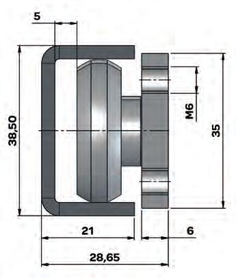
10 LAN40+LUN40 SELF-ALIGNING SYSTEMS In two-slide linear motion systems, you can use one LAN40 rail with one LUN40 rail, with PAN40 sliders in both. This combination creates a self-aligning system capable of tolerating alignment errors of up to 3.4 mm. LUN40 RAIL LUN40 RAIL LAN40+LUN40 SELF-ALIGNING SYSTEMS 10 The sliders in the LAN40 guiding rail are rigidly connected, via the mobile element, to the sliders in the LUN40 floating rail on the other side. The LAN40 guiding rail ensures play-free linear motion (see the description of points of contact on page 5). The sliders in the LUN40 floating rail are therefore also play-free but able to move axially across the flat raceways. This system avoids overload on the sliders as the result of rail alignment error. The limit of axial movement of PAN40 sliders towards the inside of LUN40 rails is determined by the size of the heads of the rail fixing screws (see figures below). In particular, T RACE s special flat head 40.VC -SP01 screws permit approximately 1 mm of extra axial movement compared to standard ISO 7380 screws. The limit of axial movement towards the outside of the LUN40 rail is determined by the point of departure of the roller from the raceway. The limit specified in the catalogue guarantees sufficient contact between rollers and raceway to support rated load. Sliders in LUN40 rails offer less load capacity than the same sliders in LAN40 rails. (See the table on page 9). Axial movement 3.4 mm Permissible alignment error Min-max movement Limit towards outside of rail Limit towards inside of rail with special 40.VC-SP01 screws Limit towards inside of rail with ISO 7380 screws


11 ROLLERS FOR LAN AND LUN SERIES RAILS As an alternative to our standard 3 and 5-roller sliders, rollers for use with LAN and LUN rails can also be mounted on custom sliders or directly on the mobile element. In such cases, the number, arrangement and types of roller need to be chosen to match the requirements of the application. See page 13 for assembly and adjustment instructions. PEN26 PCN26 All our rollers are made from core tempered and precision ground bearing grade carbon steel. Rollers are of the single row ballbearing type, with the balls held in place by a metal cage. Precision ground surfaces ensure a smooth, silent rolling action. Rollers are also fitted with 2Z rated metal shields to protect the ball bearings raceway and ensure good resistance to high temperatures. The ball bearing is lubricated for life with a wide temperature ranging lithium soap grease. The mounting axle is made in one piece with the inner bearing, for maximum strength. Rollers come in two types: eccentric and concentric. PEV30 PCV30 ROLLERS FOR LAN AND LUN SERIES RAILS 11 PEN and PCN series rollers for size 26 and 40 rails have a hexagonal recess for an Allen key in the side opposite the threaded fixing hole. This serves to hold the axle steady while the fixing screw is being tightened with a second Allen key. On eccentric rollers, it also serves to adjust roller position, so as to reach the desired preload setting. PEV and PCV rollers for size 30 rails have a special central square pivot accessible with a flat key, inserted between slider body and eccentric rollers. The flat key is supplied by TRACE. See page 12 for further instructions about Slider preload setting. PEN40 PCN40 Roller code Type Rail type Dynamic load factor C PCN26 PEN26 PCV30 PEV30 PCN40 PEN40 PCN40 PEN40 concentric eccentric concentric eccentric concentric eccentric concentric eccentric Load capacity * Co ax LAN LAN LAN LUN Weight (g)


 and complete the adjustment in the following steps: 1 - Remove the wipers from the ends")


12 PRELOAD SETTING OF SLIDERS If you order sliders pre-assembled in their rails, all adjustments are made in our factory using special tools to guarantee accurate roller alignment and a slight preload, P1, to eliminate play and ensure the smoothest possible movement. Slider preload is adjusted by means of one eccentric roller in the case of 3-roller sliders or two eccentric rollers in the case of 5-roller sliders (see page 5). The eccentric rollers must be adjusted so that they run along the raceway opposite that on which the fixed, load-bearing rollers run. The adjustment procedure is given below. STEP 1-2 SLIDER ADJUSTMENT Only adjust the eccentric rollers. Use an Allen key to engage the hexagonal recess in the roller axle (or the special flat key for PAN30 sliders) and complete the adjustment in the following steps: 1 - Remove the wipers from the ends of the slider to feel the play more easily. Tighten the eccentric roller s fixing screw until the lock washer makes firm contact but does not stop the axle turning. It must be possible to turn the eccentric axle with the Allen key smoothly while maintaining firm contact between the axle and the slider. 2 Looking from the roller side of the slider, turn the axle clockwise until the eccentric roller lines up approximately with the fixed rollers, or is only a little bit off the fixed roller raceway. Do not adjust the roller to the apex of the eccentric. 3 - Grip the rail in a vice or some other rigid support so that you do not need to hold it with your hands. Insert the carriage in the rail and engage an Allen key in the axle of the eccentric roller, through one of the holes in the rail. Looking at the slider from the screw side, turn the axle anti-clockwise until the eccentric roller rests on the raceway opposite that of the fixed rollers. As you turn the eccentric axle, turn the fixing screw in the same direction with the other Allen key to prevent it becoming looser or tighter. Use both hands. 4 - Check that there is no play in the slider by pressing alternately on both ends of the slider. Repeat this check at various points along the rail. There must be no play at any position. 5 - Hold the eccentric steady with one key and tighten the fixing screw with the other. Clockwise rotation STEP 3 Anti-clockwise rotation View from roller side 12 ADJUSTING PAN26 AND PAN40 sliders View from slider side IMPORTANT! Do not use the eccentric to loosen or tighten the roller. Use the fixing screw! 6 - You can estimate the amount of preload applied by slowly removing and re-inserting the slider from one end of the rail. Insertion force Fi is proportional to preload. Generally speaking, correct preload is indicated by an insertion force within the range given in the table. 7 - Use a torque wrench to tighten the roller fixing screw to the tightening torque Mt given in the table. Take care to hold the eccentric in position with the Allen key. On 5-roller sliders, the above adjustment procedure must be repeated for each eccentric roller. When adjusting the second eccentric roller, make sure that the roller has contacted the correct raceway by checking its direction of rotation. It must rotate in the opposite direction to the fixed rollers alongside it. The direction of roller rotation can be seen from the back of the rail through one of the mounting holes. To ensure that preload is distributed evenly between the two eccentric rollers, remove the slider from the rail and check that insertion force is identical with the slider rotated through 180 degrees. ADJUSTING PAN30 sliders The adjustment procedure is identical for PAN30 series sliders, with the sole exception that instead of using an Allen key to engage the axle through a hole in the rail, a special key is needed to pass between the slider body and the rail and engage flats on the axle. With sliders of this type, you can even adjust preload with the rail mounted on the structure. It is nevertheless preferable to adjust preload on the bench following the procedure given above. IMPORTANT! Where required, clip the wipers back in before engaging the slider in the rail. Take care to orient the slider in the direction of applied load. KLA30 flat key Slider type PAN26 PAN30 PAN40 Mt Tightening torque 7 Nm 7 Nm 12 Nm Slider type Fi Insertion force min max PAN PAN PAN40 1 6


13 ROLLER FITTING INSTRUCTIONS In addition to standard sliders, rollers can also be fitted to custom sliders or even directly to mobile elements. When doing so, the following points must be kept in mind: The minimum number of rollers is 3. Of these, 2 must be concentric rollers and located to run in the raceway of the rail that supports the main load. The third must be an eccentric roller, adjusted to run along the opposite raceway. If more than two rollers are needed to support the main load, only two must be fixed, concentric rollers. Additional load-bearing rollers must be eccentric rollers adjusted to run on the same raceway. It is important to ensure that eccentric rollers used in this way are perfectly aligned in order to distribute load equally. At least one eccentric roller must be provided and adjusted to run on the opposite raceway in order to eliminate play. Additional rollers may be needed, on the basis of the direction of load. e.g. to counteract bi-directional or overhung loads. Eccentric rollers used in this way must be located as near as possible to a concentric roller. See the table alongside for minimum distances. The arrangement and number of rollers must always be determined by the amount and direction of load applied by the element the rollers support. The overall load capacity of the assembly is limited by the maximum load capacity of the most highly loaded roller. The roller bearing that takes the greatest load should always be a concentric roller. T-RACE s Technical Assistance Service is always happy to suggest the best arrangement of rollers for specific applications. If load is supported by more than two rollers (e.g. 3, 4 or 5) on the same raceway, and load is located centrally with respect to the set of rollers, total load capacity is determined by the load capacity of one roller multiplied by the total number of rollers, reduced by a suitable safety factor depending on the accuracy of alignment of the rollers and on the rigidity of the surface to which they are fixed. Holes in the mobile element intended to fix rollers in place must be of the bare minimum diameter necessary for the fixing screw to pass through and must be of the minimum length specified in the table. STEP 1-2 Concentric Concentric P P P Adjustable eccentric Concentric Adjustable eccentric Fixed eccentric Concentric Adjustable eccentric ROLLER FITTING INSTRUCTIONS 13 Fixing screws for eccentric rollers must always be fitted with a lock washer to permit adjustment of preload. The procedure for adjusting eccentric rollers is similar to that given on page 12 for standard sliders, as are screw tightening torques. Concentric Position of rollers Concentric Concentric Adjustable eccentric NO YES Drilling of roller supports Roller type PCN26 PEN26 PCV30 PEV30 PCN40 PEN40 Minimum recommended centre to centre distance (mm) Diameter of fixing screw hole d (mm) Length of hole s min. (mm) Hole alignment error e (mm) ,1/0 1 0, ,1/0 1 0, ,1/0 1,5 0,4


14 LUBRICATION AND USE OF WIPERS Standard sliders come in two versions, with wipers (e.g. PAN26-3T) and without wipers (e.g. PAN26-3). LUBRICATION AND USE OF WIPERS 14 Wipers are made from a thermoplastic elastomer and have robust, low friction, blades that maintain contact with the raceways to remove dust and dirt and provide a clean contact surface for the rollers. The wipers also incorporate oil-impregnated felt pads that slide along the raceways, These provide additional cleaning and apply a thin film of lubricant to ensure extended rail life. Wipers clip over the axles of the end rollers and can be removed easily. In most applications, wipers provide sufficient lubrication for the entire lifetime of the rail. In certain applications in critical (e.g. dusty or dirty) environments, it may prove necessary to replace them at intervals. Sliders with wipers guarantee correct raceway lubrication and ensure an extended lifetime for the rail. They are recommended for applications involving frequent or continuous motion. Sliders without wipers are adequate for applications involving less frequent movements and are also better suited to high temperature applications that are incompatible with plastic parts. Wipers can be purchased and fitted at a later date to sliders originally supplied without wipers. Wiper fitting clip Lubricated felt pad Raceway wiper blade Hook for wiper removal Wiper code KT-LA26 KT-LA30 KT-LA40 For slider type PAN26-3 / PAN26-5 PAN30-3 / PAN30-5 PAN40-3 / PAN40-5 CHOOSING THE RIGHT SIZE Once you have chosen the best rail and slider configuration, you need to choose the right size for the static loads and lifetimes involved. To calculate static load, you need to determine the load applied to each slider. Once you have identified the slider subject to the most load, choose a suitable safety factor on the basis of maximum permissible static load. If applied load is the result of a combination of radial and axial loads and moments, you will have to determine the value of each component load and verify that: Pax + Prad + Mex + Mey + Mez <= 1 Co ax Mx My Mz Z DIRECTION OF APPLIED LOADS Mz Pax Prad Mex, Mey, Mez Coax Mx, My, Mz = axial component of applied load = radial component of applied load = applied moments = axial load capacity = radial load capacity = moment resistance capacity Z = safety factor> = 1 Mx Radial load capacity is measured only in the direction of the dots marked on the slider. Cax My RECOMMENDED VALUES: Z Operating conditions 1-1,5 Accurately determined static and dynamic loads. Precision installation, rigid structures. 1,5-2 Average conditions. 2-3,5 Inaccurate determined applied loads. Vibration, non-rigid structures. Approximate installation, unfavourable ambient conditions.
15 CALCULATION OF THEORETICAL LIFETIME The theoretical lifetime of rollers and rails can be calculated using the following conventional formula, expressed in km or travel. Bear in mind, however, that the value obtained in this way is purely indicative and must be used with caution. Actual component lifetimes under real operating conditions may differ significantly from calculated figures, since wear and fatigue depend on factors that cannot be accurately predicted, e.g.: Inaccurate initial estimates of effective load conditions Overloads caused by inaccurate assembly Vibration, pulsed dynamic stress and impacts Insufficient lubrication of raceways Wide differential changes in temperature Dusty or dirty environments Assembly errors Long travel and frequent movement CALCULATION OF THEORETICAL LIFETIME 15 PER SLIDER L (Km)= 100 ( P C ) 3 fc n fa P = Prad + ( P ax + Mex + Mey + Mez ) Corad Co ax Mx My Mz C P = dynamic load factor of slider = equivalent load applied to the slider FACTOR fc fc 1 0,75 fc = factor depending on stroke length, taking into account the fact that short strokes cause increased frequency of roller passage over the same section of raceway for the same total travel. Assign a value of 1 for strokes over 2 m; for strokes of less than 2 m, derive the value from the graph below. 0,5 0, Corsa mm n = number of sliders fa = factor depends on lubrication and ambient factors; see table for recommended values Safety factors fc and fa applied to the result of the theoretical formula are only intended as guidelines for the system designer in assessing the effect of operating conditions on real lifetime. They must not be understood as accurate indications. For further information, contact T-RACE s Technical Assistance Service. fa Operating conditions 0,7-1 Presence of wipers with lifelong lubrication pads, environment free from dust and dirt, accurate installation. 0,2-0,5 No wipers, environment with average dust and dirt, average temperature excursions and vibration. 0,05-0,1 No wipers, poor lubrication, environment with high levels of dust and dirt, wide temperature excursions and strong vibration.
16 T RACE S.p.A. Via per Cascina Restelli, Aicurzio (MB) ITALY Tel.: (+39) Fax: (+39) info@t-race.com T RACE GmbH Heide Burscheid GERMANY Phone: (+49) Fax: (+49) post@t-race.de CAT.EN
Assembly Instructions
 Assembly Instructions L INEAR R AIL R ANGE Linear Rail Mounting The availability of both countersunk (S-type) and counterbored (L-type) rail mounting holes allows optimization of alignment and orientation
Any reproduction, even partial, is allowed only by written permission by Rollco.
 EASYSLIDE Every care has been taken to ensure the accuracy of the information contained in this catalogue, but no liability can be accepted for any errors or omissions. We reserve the right to make changes
Easy Slide Rails ov -easy_slide_divider - U pdated
 Easy Slide Rails ov-easy_slide_divider - Updated - 18-09-2017 163 Easy Slide Rails Easy Slide Rails Introduction The Easy Slide family of linear rails have a compact cross-section and low-friction movement.
...components in motion. Easy Rail
 ...components in motion Easy Rail Easy Rail Introduction The Easy Rail family have a compact cross-section and low-friction movement. Robust and Long Service Life Easy Rail s range of cross-sectional rail
with MR rail and R, R.T, R.S sliders
 inear Roller earing ystem with MR rail and R, R.T, R. sliders N R R R N The MR eries inear Rail ystem consists of a -section steel rail with internal convex raceways, where robust double row ball bearing
DISCOVER THE NATURAL STRENGTH OF THE BEST ROLLER LINEAR GUIDE
 HIGH PERFORMANCE ADVANTAGES OF LINEAR ROLLER MRG - MR SLIDES ADVANTAGES DISCOVER THE NATURAL STRENGTH OF THE BEST ROLLER LINEAR GUIDE Catalog Data for MRG and MR Series Only USA Contact: The Precision
Redi-Rail Linear Guides
 Redi-Rail Linear Guides Product Overview PRODUCT OVERVIEW Sealed double row bearings provide maintenance free, smooth linear guidance Side adjusted preload makes greatly simplifies assembly and installation
Miniature Ball Rail Systems
 R310EN 2210 (2004.06) The Drive & Control Company 2 Bosch Rexroth AG Linear Motion and Assembly Technologies Miniature-BRS R310EN 2210 (2004.06) Linear Motion Systems Ball Rail System Standard Ball Rail
LINEAR ROLLER SYSTEM with MR rail and R, R.T, R.S sliders
 NR R R N NR ROR YTM with MR rail and R, R.T, R. sliders The MR eries inear Rail ystem consists of a -section steel rail with internal convex raceways, where robust double row ball bearing rollers travel.
carriages to carry the load (taking into account any moment loads). Unlike the N series sliders these CS sliders do not have protective side seals.
. Unlike the N series sliders these CS sliders do not have protective side seals.") Light Duty Sliders, size 18 no side seal, front fixing Long Linear s L1918.CS Material Zinc plated steel body. Steel rollers (100Cr6) with metal (2Z) or rubber (2RS) seals. Technical notes To be used with
Light Duty Sliders, size 18 no side seal, front fixing Long Linear s L1918.CS Material Zinc plated steel body. Steel rollers (100Cr6) with metal (2Z) or rubber (2RS) seals. Technical notes To be used with
Courtesy of CMA/Flodyne/Hydradyne Motion Control Hydraulic Pneumatic Electrical Mechanical (800)
") 01_1 Miniature st Headline_36 Ball Rail pt/14.4 Systems mm second line 2 Linear Motion and Assembly Technologies Miniature Ball Rail Systems Ball Rail Systems Roller Rail Systems Linear Bushings and Shafts
01_1 Miniature st Headline_36 Ball Rail pt/14.4 Systems mm second line 2 Linear Motion and Assembly Technologies Miniature Ball Rail Systems Ball Rail Systems Roller Rail Systems Linear Bushings and Shafts
TELESCOPIC RAILS HARDENED TELESCOPIC RAILS FOR HIGHLY DYNAMIC APPLICATIONS 7.1 PRODUCT OVERVIEW 7.2 PART EXTENSIONS 7.
 7 TELESCOPIC RAILS HARDENED TELESCOPIC RAILS FOR HIGHLY DYNAMIC APPLICATIONS PAGE 106 PAGE 116 PAGE 120 PAGE 126 7.1 PRODUCT OVERVIEW 7.2 PART EXTENSIONS 7.3 FULL EXTENSIONS 7.4 LINEAR GUIDES 105 PRODUCT
TELESCOPIC-LINE. Semi-telescopic-rail LST. Telescopic-rail LSE. Linear guides with ball-cage LSS
 TELESCOPIC-LINE Semi-telescopic-rail LST Telescopic-rail LSE Linear guides with ball-cage LSS 1 Ball rails LSS, LST and LSE The ball rails produced by Nadella are very compact and flexible products. Made
INDEX EASY RAIL: THE SOLUTION IS EASY...D4 EXAMPLES OF LOAD CAPACITIES...D5 ORDER CODES...D6 MOUNTING EXAMPLES...D7 TECHNICAL DATA...
 INDEX EASY RAIL: THE SOLUTION IS EASY...D4 EXAMPLES OF LOAD CAPACITIES...D5 ORDER CODES...D6 MOUNTING EXAMPLES...D7 TECHNICAL DATA...D8 STANDARD CONFIGURATIONS...D10 VERIFICATION UNDER STATIC LOAD...D12
Version with light play G1 G1 version with light play over total stroke for minor friction and/or to allow some minor compensation of assembly error.
 T elescopic s lides R N LL-C Telescopic slides The all-cage T RC telescopic slides range are the most advanced ballcage slides. They offer the best ratio capacity load / size available on the market with
X-Rail FrontespizioXRai.indd 1 07/10/ :30:14
 X-Rail 1 Product explanation Product explanation X-Rail: orrosion resistant or zinc-plated steel linear bearings ig. 1 X-Rail is the product family of roller embossed guide rails for applications in which
...components in motion. Miniature Linear Guideways
 ...components in motion Miniature Linear Introduction Miniature linear guideway systems are widely used throughout industry for precise, compact applications. Precise and Stainless The gothic arch shape
LA rails with. R.S series sliders. PA. series sliders ,5 37,2 24,3 28,20 18,30 14,8 18,2 28,2 28,6
 Monorace RN 18 MR rails with R. series sliders. 37 24 16,5 MR rails with R.T series sliders. 37,2 24,3 18 MR rails with R. series sliders.,20 18,30 14,8 M rails with R series sliders. M rails with R. series
Linear Guideways ov -linear -guidew ays-divider - U pdated
 Linear Guideways ov-linear-guideways-divider - Updated - 11-01-2017 163 Linear Guideways Linear Guideways Introduction L1016 Linear guideways Linear guideways are widely used throughout industry for heavy-duty
FUNCTION OF A BEARING
 Bearing FUNCTION OF A BEARING The main function of a rotating shaft is to transmit power from one end of the line to the other. It needs a good support to ensure stability and frictionless rotation. The
Temporary. Catalogue English. Catalogue
 Temporary Catalogue Catalogue English www.rollon.com INDICE CATALOGO We design and produce in order to support you 4-5 A complete range for linear motion 6-7 MONORACE High Performance advantages of linear
Any reproduction, even partial, is allowed only by written permission by Rollco.
 LINEAR UNIT E-SMART Every care has been taken to ensure the accuracy of the information contained in this catalogue, but no liability can be accepted for any errors or omissions. We reserve the right to
Axial-radial cylindrical roller bearings
 Axial-radial cylindrical roller bearings Designs and variants.............. 320 Bearing data..................... 321 (Boundary dimensions, tolerances) Product table 5.1 Axial-radial cylindrical roller
TELESCOPIC RAIL HEAVY
 TELESCOPIC RAIL HEAVY Every care has been taken to ensure the accuracy of the information contained in this catalogue, but no liability can be accepted for any errors or omissions. We reserve the right
Heavy-Duty Rod Ends - Male with integral spherical plain bearing
 Heavy-Duty Rod Ends - Male with integral spherical plain bearing 65700 Order No. Thread (hand) d 1 l 1 d 2 d 3 d 4 l 2 l 3 X g H7 65700.W0005 Right 5 33 M 5 11,11 18 20 9 14 65700.W0006 Right 6 36 M 6
Ball Rail Systems RE / The Drive & Control Company
 Ball Rail Systems RE 82 202/2002-12 The Drive & Control Company Rexroth Linear Motion Technology Ball Rail Systems Roller Rail Systems Standard Ball Rail Systems Super Ball Rail Systems Ball Rail Systems
Profi le rail guides LLR
 Profi le rail guides LLR Content The SKF brand now stands for more than ever before, and means more to you as a valued customer. While SKF maintains its leadership as the hallmark of quality bearings throughout
LoPro aluminium based slide system
 LoPro aluminium based slide system Introducing the Hepco LoPro Hepco LoPro has been introduced to provide the designer with a lightweight yet rugged linear slide system. LoPro is aluminiumbased with steel
Dynamic Elements Linear Slides Mechanical Drive Elements Accessories for Mechanical Drive Elements
 8 Dynamic Elements Mechanical Drive Elements Accessories for Mechanical Drive Elements The Dynamic Elements product group of the MB Building Kit System contains components which enable precise linear movement.
Inner block. Grease nipple. Fig.1 Structure of LM Guide Actuator Model KR
 LM Guide ctuator Model LM Guide + all Screw = Integral-structure ctuator Stopper Housing all screw Inner block Grease nipple Outer rail earing (supported side) Housing Stopper Double-row ball circuit earing
Linear Drive with Ball Screw Drive Series OSP-E..SB
 Linear Drive with Ball Screw Drive Series OSP-E..SB Contents Description Data Sheet No. Page Overview 1.30.001E 47-50 Technical Data 1.30.002E-1 to 5 51-55 Dimensions 1.30.002E-6, -7 56-57 Order instructions
Rodless Pneumatic Cylinders Series OSP-P
 Rodless Pneumatic Cylinders Series OSP-P System Concepts & Components... 2-5 Technical Data... 7-9 Dimensions... 10-15 Active rakes... 16-19 Accessories (Mounts & Supports)... 20-29 Ordering Information...30
Crossed Roller Ways. Description of each series and Table of dimensions. Anti-Creep Cage Crossed Roller Way
 Crossed Roller Ways Description of each series and Table of dimensions Crossed Roller Way Page - to -7 Anti-Creep Cage Crossed Roller Way Page - to - Crossed Roller Way Unit Page - to - In the table of
seals Molded plastic casing Spring-load for even pressure. High speed & acceleration wt MOUNTING RR XX XXXX
 LINEAR GUIDES features & BENEFITS Easy adjusting - patented pre-load adjustment eliminates eccentrics Integral seals Bearings sealed against contamination Gothic arch rollers Maximum temperature approximately
SRG. Caged Roller LM Guide Ultra-high Rigidity Type Model SRG. Point of Selection. Point of Design. Options. Model No. Precautions on Use
 Caged Roller LM Guide Ultra-high Rigidity Type Model LM block LM rail End seal Endplate 45 45 Caged roller Roller 45 Cross section 45 * or the caged roller, see. Point of Selection A Point of Design Options
R310EN 2211 ( ) The Drive & Control Company
 The Drive & Control Company") eline Ball Rail Systems R310EN 2211 (2006.04) The Drive & Control Company Bosch Rexroth AG Linear Motion and Assembly Technologies Ball Rail Systems Roller Rail Systems Linear Bushings and Shafts Ball
eline Ball Rail Systems R310EN 2211 (2006.04) The Drive & Control Company Bosch Rexroth AG Linear Motion and Assembly Technologies Ball Rail Systems Roller Rail Systems Linear Bushings and Shafts Ball
LINEAR RAIL BALL CHAIN TYPE
 LINEAR RAIL BALL CAIN TYPE Svanemærket tryksag 54-73 INDEX Index Product overview... 4-5 Dimension table RC/ERC... 6-7 Dimension table RC... 8-9 Dimension table ARC... 0-3 Dimension table & Grease... 4
Lubrication for Linear Roller Bearings and Raceways
 WHITE PAPER Lubrication for Linear Roller Bearings and Raceways Minimize Corrosion and Maximize the Life of Linear Roller Bearing Systems Introduction Linear roller bearing systems offer distinct advantages
Берг АБ Тел. (495) , факс (495)
 , факс (495)") AUTOMATION Linear- and Rotary Modules Table of Contents 1 Product Overview............................................. 4 1.1 Selection of the Linear Modules................................. 8 1.2 Selection
AUTOMATION Linear- and Rotary Modules Table of Contents 1 Product Overview............................................. 4 1.1 Selection of the Linear Modules................................. 8 1.2 Selection
...our linkages, your solution. Rod Ends
 ...our linkages, your solution Technical Information Introduction All of our rod ends incorporate either a plain spherical bearing, ball bearing, or roller bearing. Below is an overview of each type. Plain
Precision Linear Pack
 Precision Linear Pack General Catalog A Technical Descriptions of the Products B Product Specifications (Separate) Features... Features of the Precision Linear Pack... Structure and features... Rated Load
Ball screw drives KGT General technical data
 KGT General technical data Manufacturing process The thread profile is produced by cold rolling in the thread rolling method. Both screw and nut have a gothic thread profile. The load angle is 45. Linear
Ball. Ball cage. Fig.1 Structure of Caged Ball LM Guide Actuator Model SKR
 Caged all LM Guide Actuator Model Inner block all screw shaft Grease nipple Outer rail all cage all Structure and Features Fig.1 Structure of Caged all LM Guide Actuator Model Caged all LM Guide Actuator
Profile rail guides LLT
 Profile rail guides LLT Contents The SKF brand now stands for more than ever before, and means more to you as a valued customer. While SKF maintains its leadership as the hallmark of quality bearings throughout
V SWISS MADE LINEAR TECHNOLOGY
 Compact units Excerpt from main catalogue SWISS MADE LINEAR TECHNOLOGY V 11-15 Line Tech compact units Table of contents Product overview 106 107 Design fundamentals / Lubrication / Maintenance 108 Profile
EMC-HD. C 01_2 Subheadline_15pt/7.2mm
 C Electromechanical 01_1 Headline_36pt/14.4mm Cylinder EMC-HD C 01_2 Subheadline_15pt/7.2mm 2 Elektromechanischer Zylinder EMC-HD Short product name Example: EMC 085 HD 1 System = ElectroMechanical Cylinder
10 Thrust ball bearings
 10 Thrust ball bearings Designs and variants.............. 1010 Single direction thrust ball bearings... 1010 Double direction thrust ball bearings.. 1010 Cages............................ 1010 Bearings
ECOLINE: AFFORDABLE AND INNOVATIVE LINEAR BEARINGS
 ECOLINE: FFORDBLE ND INNOVTIVE LINER BERINGS ECOLINE s products have been designed to fit in applications where quality movement is needed at a low price. The patented design offers a well-protected, smooth
Installation and Operational Instructions for EAS - HTL housed overload clutch Sizes 01 3 Type 490._24.0
 Please read these Operational Instructions carefully and follow them accordingly! Ignoring these Instructions may lead to malfunctions or to clutch failure, resulting in damage to other parts. Contents:
EASY RAIL.
 EASY RAIL www.rollon.com About Rollon Development of global business Continual expansion and optimization of the portfolio 1975 Parent company, Rollon S.r.l., founded in Italy 1991 Founding of Rollon GmbH
Linear Guides Series OSP-E
 Linear Guides Series OSP-E NEW Contents Description Data Sheet No. Page Overview 1.40.020E 101-102 Plain Bearing SLIDELINE 1.40.021E 103-104 Roller Guide POWERSLIDE 1.40.022E 105-108 Aluminium Roller Guide
TRANSLATION (OR LINEAR)
") 5) Load Bearing Mechanisms Load bearing mechanisms are the structural backbone of any linear / rotary motion system, and are a critical consideration. This section will introduce most of the more common
5) Load Bearing Mechanisms Load bearing mechanisms are the structural backbone of any linear / rotary motion system, and are a critical consideration. This section will introduce most of the more common
Linear Drive with Toothed Belt and Integrated Guide with Recirculating Ball Bearing Guide with Roller Guide Series OSP-E..BHD
 Linear Drive with and Integrated Guide with Recirculating Ball Bearing Guide with Roller Guide Contents Description Page Overview 11-14 Version with Recirculating Ball Bearing Guide Technical Data 15-17
Guide Wheel System Properties, Selection & Sizing
 Guide System Properties, Selection & Sizing Brett Frederick, Project Engineer, C.G. Bretting Manufacturing Kevin Kegel, AssemblySpecialist, C.G. Bretting Manufacturing Paper dust particulates wreak havoc
ORIGA Pneumatic Linear Drives OSP-L
 ORIGA Pneumatic Linear Drives OSP-L Very long lifetime and lowest leakage A NEW Modular Linear Drive System With this second generation linear drive Parker Origa offers design engineers complete flexibility.
LM76 Linear Motion Bearings
 LM76 Linear Motion Bearings ROLLER BEARING PILLOW BLOCKS PDF FILE PDF FILE INDEX PAGE ADVANTAGES 1 DIMENSIONAL TABLES Single Pillow Blocks (SPB) 2 Double Pillow Blocks (DPB) 2 Twin Pillow Blocks (TWN)
The gear boxes can be run at the same speeds as the actuator models. Do not exceed torque ratings.
 1. What is the lifting torque required? The lifting torque for a single actuator depends on the load, the worm gear ratio, type of screw (machine cut or ball screw) and the pitch of the lifting screw.
506E. LM Guide Actuator General Catalog
 LM Guide Actuator General Catalog A LM Guide Actuator General Catalog A Product Descriptions 506E Caged Ball LM Guide Actuator Model SKR.. A2-4 Structure and Features... A2-4 Caged Ball Technology... A2-6
SHANGHAI SHINING-SUN INTERNATIONAL CO.,LTD Tel : Fax :
 TLS The TLS are full telescopic slides, composed of 2 semi-telescopic slides fixed to a robust S-shaped intermediate element, to provide high load capacities with min. flexion. ouble full stroke versions
4 Self aligning ball bearings
 Rolling bearings 4 Self aligning ball bearings Designs and variants... 538 Basic design bearings... 539 Bearings with an extended inner ring.. 540 Cages... 540 Sealing solutions... 540 Greases for sealed
Base-Line. DC, C Systems
 DC, C Systems DC system DC system is based on rails, guide rollers and carriages that provide a complete guiding system. Rails and rollers can be used as single elements. In most cases the application
Chapter 11 Rolling Contact Bearings
 Chapter 11 Rolling Contact Bearings 1 2 Chapter Outline Bearing Types Bearing Life Bearing Load Life at Rated Reliability Bearing Survival: Reliability versus Life Relating Load, Life, and Reliability
MAIN SHAFT SUPPORT FOR WIND TURBINE WITH A FIXED AND FLOATING BEARING CONFIGURATION
 Technical Paper MAIN SHAFT SUPPORT FOR WIND TURBINE WITH A FIXED AND FLOATING BEARING CONFIGURATION Tapered Double Inner Row Bearing Vs. Spherical Roller Bearing On The Fixed Position Laurentiu Ionescu,
R310EN 2302 ( ) The Drive & Control Company
 The Drive & Control Company") R31EN 232 (26.4) The Drive & Control Company Bosch Rexroth AG Linear Motion and Assembly Technologies Ball Rail Systems Linear Bushings and Shafts Ball Screw Drives Linear Motion Systems Basic Mechanical
R31EN 232 (26.4) The Drive & Control Company Bosch Rexroth AG Linear Motion and Assembly Technologies Ball Rail Systems Linear Bushings and Shafts Ball Screw Drives Linear Motion Systems Basic Mechanical
T E L E S C O P I C S L I D E S R A N G E
 T E L E S C O P I C S L I D E S R A N G E The TLR., TLQ. telescopic slides series are designed for applications with motorized movement, requiring high frequency and smooth movement, this thanks to double-row
ORIGA SYSTEM PLUS Guides, Brakes and Valves for Modular Linear Drive Systems OSP Appendix to the Operating Instructions
 ORIGA SYSTEM PLUS Guides, Brakes and Valves for Modular Linear Drive Systems OSP Appendix to the Operating Instructions TAll personnel who have anything to do with the OSP fitted with guides, brakes or
Contents. Page. 1. Product description. 2. The AXC line of linear axes. 3. AXLT line of linear tables. AXC and AXS product overview...
 SNR Industry Contents Page 3 1. Product description AXC and AXS product overview... 6-8 Dynamic load ratings of the linear motion systems... 9 Compact modules... 10-11 Linear tables... 12 Telescopic axes...
Features of the LM Guide
 Features of the Functions Required for Linear Guide Surface Large permissible load Highly rigid in all directions High positioning repeatability Running accuracy can be obtained easily High accuracy can
Linear Guide Systems for Low Contamination and Highly Corrosive Environments
 Linear Guide Systems for Low Contamination and Highly Corrosive Environments By Leslie Lui, Mechanical Design Engineer Bishop-Wisecarver Corporation Pittsburg, CA www.bwc.com info@bwc.com (925) 439-8272
Linear Actuator with Ball Screw Series OSP-E..S. Contents Description Overview Technical Data Dimensions 79
 Linear Actuator with Ball Screw Series OSP-E..S Contents Description Page Overview 71-74 Technical Data 75-78 Dimensions 79 71 The System Concept ELECTRIC LINEAR ACTUATOR FOR HIGH ACCURACY APPLICATIONS
RSR. LM Guide Miniature Types Model RSR. Point of Selection. Point of Design. Options. Model No. Precautions on Use
 LM Guide Miniature Types Model Endplate LM block End seal LM rail Ball Grease nipple Cross section Point of Selection A Point of Design Options Model No. Precautions on Use Accessories for Lubrication
Cross Roller Guide/Ball Guide General Catalog
 General Catalog A Product Descriptions Features and Types... A7-2 Features of the.. A7-2 Structure and Features... A7-2 Types of the.. A7-3 Types and Features... A7-3 Point of Selection... A7-4 Rated Load
High precision and super light. Angular contact roller bearings from INA
 High precision and super light Angular contact roller bearings from INA Angular contact roller bearings High precision and super light The limits of conventional ball reaching their performance limits
Locking Assemblies Shrink Discs Rigid Couplings.
 M I N I Locking Assemblies Shrink Discs Rigid Couplings www.mav.it our company We are an Italian company world renowned for our creativity and ethics. Established in 1989 we have rapidly built a reputation
DS 0002 MOV 2014 DISTITEC Srl
 DS 0002 MOV 2014 DISTITEC Srl The realization of this catalog occurred in tighter control of data contained therein. Due to the ongoing technical evolution of our products, we reserve the right to make
CURVE AND LINEAR TRACK
 URVE AND LINEAR TRAK About US SAIBO is one of world recognized leaders in design and manufacturing of low friction linear motion components and precision bearings. SAIBO products are exported to over
KTR Torque Limiters Overload Protection Systems
 KT Torque Limiters Overload Protection Systems UFLEX - Friction Disk - Zero Backlash Ball Detent KT SI - Ball/oller Bearing Style KT SI Compact - Zero Backlash Ball Detent Catalog Contents (Metric) Page
...components in motion. Linear Guideways
 ...components in motion Linear 3 Linear Technical Information Linear Linear guideways are widely used throughout industry for heavy duty and precise applications. Linear from Automotion Components The
Slotted nut NMG. Housing nut GWR. Bosch Rexroth AG. for economical constructions. a min. 0,3. M A = tightening torque of slotted nut.
 R310EN 3301 (2009.08) Precision Ball Screw Assemblies Bosch Rexroth AG 113 Slotted nut NMG for economical constructions B D d d1 b M A = tightening torque of slotted nut a min. 0,3 Polyamide insert Designation
MM FIXED ADJUSTABLE PLATE FIXED ADJUSTABLE RADIAL AXIAL A B C D E
 Hevi-Rail Roller Bearings and Linear Guideways SYSTEM MAX. STATIC COMBINED HEVI-RAIL BEARING WITH WELDED LOAD* GENERAL DIMENSIONS** BEARING FLANGE PLATE kn MM FLANGE FIXED ADJUSTABLE PLATE FIXED ADJUSTABLE
GN Telescope-Linear motion bearings
 GN 2410 Telescope-Linear motion bearings technical informations Specification Rail / Runner Heat treatable steel - zinc plated, blue passivated - Raceways hardened Balls Anti-friction bearing steel, hardened
Shaft-Hub-Connections
 Stand: 14.01.2010 Shaft-Hub-Connections Shrink Discs Cone Clamping Elements Star Discs 36 Edition 2012/2013 RINGSPANN Eingetragenes Warenzeichen der RINGSPANN GmbH, Bad Homburg Table of Contents Introduction
TRACK GUIDANCE SYSTEMS
 EURO-BEARINGS LTD TRACK GUIDANCE SYSTEMS www.euro-bearings.com Tel. 01908 511733 email: sales@euro-bearings.com INTRODUCTION EURO-BEARINGS LTD www.euro-bearings.com Tel. 01908 511733 This linear guidance
Linear Drive with Toothed Belt Series OSP-E..B. Contents Description Overview Technical Data Dimensions Order Instructions 46
 Linear Drive with Toothed Belt Contents Description Page Overview 35-38 Technical Data 39-43 Dimensions 44-45 Order Instructions 46 35 The System Concept ELECTRIC LINEAR DRIVE FOR POINT-TO-POINT APPLICATIONS
Index INDEX. Product overview Technical data... 5 RHL Sliders for RHL80: V100, V250 & V RHL
 LINEAR UNIT RHL Svanemærket tryksag 541-713 INDEX Index Product overview... 4 Technical data... 5 RHL... 6 Sliders for RHL: V1, V25 & V5... 7 RHL11... 8 Sliders for RHL11: V2 & V5... 9 Mounting Plates...
 A LEADING MANUFACTURER IN LINEAR MOTION GERALD SUMMERS is now an authorised distributor of Rollon TEL: 0800 055 6663 E-MAIL: SALES@GERALD-SUMMERS.CO.UK WWW.GERALD-SUMMERS.CO.UK CURVILINE www.rollon.com
...components in motion. Curviline Rail
 ...components in motion Curviline Curviline Introduction The Curviline rail system offers a cost-effective solution to curvi-linear applications. Flexibility when you need it Constant radius, variable
drylin N Low-Profile Guide Systems
 drylin N Low-Profile Guide Systems Low-profile height and width Replaceable polymer sliding pads Anodised aluminium rail High speed and acceleration possible Lubrication-free Low weight 925 drylin N drylin
Linear Actuator with Ball Screw Series OSP-E..S. Contents Description Overview Technical Data Dimensions 89
 Linear Actuator with Ball Screw Series OSP-E..S Contents Description Page Overview 79-82 Technical Data 83-88 Dimensions 89 79 The System Concept ELECTRIC LINEAR ACTUATOR FOR HIGH ACCURACY APPLICATIONS
Guide plate. Fig. 1 Construction of Slide Pack Type FBW-RUU
 A Slide Pack Slide Pack Type FBW Japanese patent No. 1696446 Overseas patent resistered in the U.S. Mounting plate Ball Slide rail Seal Guide plate Stopper Fig. 1 Construction of Slide Pack Type FBW-RUU
Any reproduction, even partial, is allowed only by written permission by Rollco.
 COMPACT RAIL Every care has been taken to ensure the accuracy of the information contained in this catalogue, but no liability can be accepted for any errors or omissions. We reserve the right to make
Single direction thrust ball bearings Double direction thrust ball bearings
 Thrust ball bearings Single direction thrust ball bearings... 838 Double direction thrust ball bearings... 839 Bearing data general... 840 Dimensions... 840 Tolerances... 840 Misalignment... 840 Cages...
Labyrinth seals for INA ball bearings
 Labyrinth seals for INA ball bearings Dipl.-Ing. Günter Gerhart and Dipl.-Ing. Michael Kurz INA reprint October 1995 Labyrinth seals for INA ball bearings Dipl.-Ing. Günter Gerhart and Dipl.-Ing. Michael
ACTUATORS GENERAL CATALOG
 CAD drawing data catalog is available. ACTUATORS GENERAL CATALOG ROTARY ACTUATORS VANE TYPE SERIES CONTENTS RAN (Standard Type) Basic Model and Configuration 259 Specifications 26 Order Codes 264 Dimensions
ELECTRIC ACTUATOR - RODLESS ELEKTRO SK SERIES ACTUATORS
 ELECTRIC ACTUATOR - RODLESS ELEKTRO SK SERIES 1 ELECTRIC AXIS - RODLESS ELEKTRO SK SERIES Electric axis without screw piston rod, with V-Lock interface. The cylinder frame is made of anodized extruded
LINEAR TABLES
 LINEAR TABLES LINEAR TABLES NIASA'S LINEAR TABLES are translating units that can be easily controlled manually or commanded by CNC. Due to their lightness and ease of application they are very useful elements
CLASSIFICATION OF ROLLING-ELEMENT BEARINGS
 CLASSIFICATION OF ROLLING-ELEMENT BEARINGS Ball bearings can operate at higher speed in comparison to roller bearings because they have lower friction. In particular, the balls have less viscous resistance
DryLin R Linear Plain Bearings, Fast and Quiet
 +90º 40º +250º 100º Linear Plain Bearings, Fast and Quiet linear plain bearings, made from solid polymers, are dimensionally equivalent to standard ball bearings. They are made entirely of wear resistant
Precision Miniature Ball Screw
 Brief introduction of Precision Miniature Ball Screw Precision Miniature ball screw assemblies are conventionally understood to be systems with a nominal diameter of 16mm or less. Their miniaturized nut
EPT Mounted Bearing Technical Support. Phone: FAX: Mounted Bearing Application Engineering
 ENGINEERING EPT Mounted Bearing Technical Support Browning Technical Services Phone: 606-564-2093 FAX: 606-564-2079 Mounted Bearing Application Phone: 219-465-2211 FAX: 219-465-2290 E-mail: browningbearing.eng@emerson-ept.com