TWO STAGE/TWO CYLINDER AIR COMPRESSORS & UNITS FEATURING THE R10 & R15 PUMPS
|
|
|
- Allan Harvey
- 5 years ago
- Views:
Transcription


 C452-B (Ref.")
1 OPERATION/MAINTENANCE MANUAL & PARTS LIST TWO STAGE/TWO CYLINDER AIR COMPRESSORS & UNITS FEATURING THE R0 & R5 PUMPS THIS MANUAL CONTAINS IMPORTANT SAFETY INFORMATION AND SHOULD ALWAYS BE AVAILABLE TO THOSE PERSONNEL OPERATING THIS UNIT. READ, UNDERSTAND AND RETAIN ALL INSTRUCTIONS BEFORE OPERATING THIS EQUIPMENT TO PREVENT INJURY OR EQUIPMENT DAMAGE. C453-B (Ref. Drawing) C452-B (Ref. Drawing) MODEL R5B COMPRESSOR MODEL HR2-6 UNIT Form No. F323 VER: 6 09/29/200
2 MAINTAIN COMPRESSOR RELIABILITY AND PERFORMANCE WITH GENUINE CHAMPION COMPRESSOR PARTS AND SUPPORT SERVICES Champion Compressor genuine parts, manufactured to design tolerances, are developed for optimum dependability specifically for Champion compressor systems. Design and material innovations are the result of years of experience with hundreds of different compressor applications. Reliability in materials and quality assurance are incorporated in our genuine replacement parts. Your authorized Champion Compressor distributor offers all the backup you ll need. A worldwide network of authorized distributors provides the finest product support in the air compressor industry. Your authorized distributor can support your Champion air compressor with these services:. Trained parts specialists to assist you in selecting the correct replacement parts. 2. A full line of factory tested CHAMPLUB compressor lubricants specifically formulated for use in Champion compressors. 3. Repair and maintenance kits designed with the necessary parts to simplify servicing your compressor. Authorized distributor service technicians are factory trained and skilled in compressor maintenance and repair. They are ready to respond and assist you by providing fast, expert maintenance and repair services. For the location of your local authorized Champion Air Compressor distributor, refer to the yellow pages of your phone directory or contact: Factory: Champion 30 North Euclid Avenue Princeton, IL 6356 Phone: (85) Fax: (85) Champion@Championpneumatic. com INSTRUCTIONS FOR ORDERING REPAIR PARTS When ordering parts, specify Compressor MODEL, HORSEPOWER and SERIAL NUMBER (see nameplate on unit). All orders for Parts should be placed with the nearest authorized distributor. Order by part number and description. Reference numbers are for your convenience only. 2
3 TABLE OF CONTENTS Subject Page Safety And Operation Precautions... 4 Explanation Of Safety Instructions Symbols And Decals... 5 Introduction... 6 Warranty... 6 Dimensions And Specifications... 7 Installation... 8, 9, 0 & Operation... & 2 Maintenance... 3,4, 5 & 6 Compressor Oil Specifications... 7 Lubricant... 7 Torque Valves... 7 Trouble Shooting Guide... 8 & 9 Parts List thru 3 Constant Speed Head Unloader Kit Unit Hazard Decal & Tags & 34 Pump Hazard Decals & Tags
4 SAFETY AND OPERATION PRECAUTIONS Because an air compressor is a piece of machinery with moving and rotating parts, the same precautions should be observed as with any piece of machinery of this type where carelessness in operation or maintenance is hazardous to personnel. In addition to the many obvious safety rules that should be followed with this type of machinery, the additional safety precautions as listed below must be observed:. Read all instructions completely before operating air compressor or unit. 2. For installation, follow all local electrical and safety codes, as well as the National Electrical Code (NEC) and the Occupational Safety and Health Act (OSHA). 3. Electric motors must be securely and adequately grounded. This can be accomplished by wiring with a grounded, metal-clad raceway system to the starter; by using a separate ground wire connected to the bare metal of the motor frame; or other suitable means. 4. Protect the power cable from coming in contact with sharp objects. Do not kink power cable and never allow the cable to come in contact with oil, grease, hot surfaces, or chemicals. 5. Make certain that the power source conforms to the requirements of your equipment. 6. Pull main electrical disconnect switch and disconnect any separate control lines, if used, before attempting to work or perform maintenance on the air compressor or unit. "Lock out" or "Tag out" all power sources. 7. Do not attempt to remove any compressor parts without first relieving the entire system of pressure. 8. Do not attempt to service any part while machine is in an operational mode. 9. Do not operate the compressor at pressures in excess of its rating. 0. Do not operate compressor at speeds in excess of its rating.. Periodically check all safety devices for proper operation. Do not change pressure setting or restrict operation in any way. 2. Be sure no tools, or rags or loose parts are left on the compressor or drive parts. 3. Do not use flammable solvents for cleaning the air inlet filter or element and other parts. 4. Exercise cleanliness during maintenance and when making repairs. Keep dirt away from parts by covering parts and exposed openings with clean cloth or Kraft paper. 5. Do not operate the compressor without guards, shields and screens in place. 6. Do not install a shut-off valve in the discharge line, unless a pressure relief valve, of proper design and size, is installed in the line between the compressor unit and shut-off valve. 7. Do not operate compressor in areas where there is a possibility of ingesting flammable or toxic fumes. 8. Be careful when touching the exterior of a recently run motor - it may be hot enough to be painful or cause injury. With modern motors this condition is normal if operated at rated load - modern motors are built to operate at higher temperatures. 9. Inspect unit daily to observe and correct any unsafe operating conditions found. 20. Do not "play around" with compressed air, nor direct air stream at body, because this can cause injuries. 2. Compressed air from this machine absolutely must not be used for food processing or breathing air without adequate downstream filters, purifiers and controls. 22. Always use an air pressure regulating device at the point of use, and do not use air pressure greater than marked maximum pressure of attachment. 23. Check hoses for weak or worn condition before each use and make certain that all connections are secure. 24. Always wear safety glasses when using compressed air gun. The user of any air compressor package manufactured by Champion A Gardner Denver Co., is hereby warned that failure to follow the preceding Safety and Operation Precautions can result in injuries or equipment damage. However, Champion A Gardner Denver Co., does not state as fact or does not mean to imply that the preceding list of Safety and Operating Precautions is all inclusive, and further that the observance of this list will prevent all injuries or equipment damage. 4
5 EXPLANATION OF SAFETY INSTRUCTIONS SYMBOLS AND DECALS DANGER Indicates immediate hazards which will result in severe injury or death. WARNING Indicates hazards or unsafe practice which could result in severe injury or death. CAUTION Indicates hazards or unsafe practice which could result in damage to the Champion compressor or minor injury. NOTICE Notice is used to notify people of installation, operation or maintenance information which is important but not hazard-related. SAFETY AND OPERATION PRECAUTIONS OBSERVE, UNDERSTAND AND RETAIN THE INFORMATION GIVEN IN THE SAFETY PRECAUTION DECALS AS SHOWN IN THE PARTS LIST SECTION DANGER This reciprocating compressor must not be used for breathing air. To do so will cause serious injury whether air is supplied direct from the compressor source or to breathing tanks for later use. Any and all liabilities for damage or loss due to injury, death and/or property damage including consequential damages stemming from the use of this compressor to supply breathing air, will be disclaimed by the manufacturer. WARNING The use of this compressor as a booster pump and/or to compress a medium other than atmospheric air is strictly non-approved and can result in equipment damage and/or injury. Nonapproved uses will also void the warranty. CAUTION This unit may be equipped with special options which may not be included in this manual. User must read, understand and retain all information sent with special options. 5
6 INTRODUCTION Champion R Series compressor are the result of advanced engineering and skilled manufacturing. To be assured of receiving maximum service from this machine the owner must exercise care in its operation and maintenance. This book is written to give the operator and maintenance department essential information for dayto-day operation, maintenance and adjustment. Careful adherence to these instructions will result in economical operation and minimum downtime. Champion Five Year Warranty "R" Series Compressors CHAMPION warrants each new compressor pump manufactured by CHAMPION, mounted on a factory assembled unit, to be free from defects in material and workmanship under normal use and service for a period of sixty (60) months from date of installation or sixty-six (66) months from date of shipment by CHAMPION or CHAMPION distributor, whichever may occur first. Applies to the compressor pump only, excluding head valves. Valves, controls and accessories are warranted for the first year only. Compressor pumps purchased separately would carry a one year warranty. This five year extended warranty will be prorated over the 5 years as follows: First Year - 00% Allowance, Parts and Labor Second Year - 90% Allowance, Parts and Labor Third Year - 80% Allowance, Parts and Labor Fourth Year - 70% Allowance, Parts and Labor Fifth Year - 60% Allowance, Parts and Labor Applies to CHAMPION logo, tank or base mounted complete compressors only. Express Limited Warranty CHAMPION warrants each new air compressor unit manufactured by CHAMPION to be free from defects in material and workmanship under normal use and service for a period of twelve (2) months from date of installation or eighteen (8) months from date of shipment by CHAMPION or CHAMPION distributor, whichever may occur first. CHAMPION makes no warranty in respect to components and accessories furnished to CHAMPION by third parties, such as ELECTRIC MOTORS, GASOLINE ENGINES and CONTROLS, which are warranted only to the extent of the original manufacturer's warranty to CHAMPION. To have warranty consideration, electric motors must be equipped with thermal overload protection. The extended five year warranty will apply to ASME air receivers provided they are installed on rubber vibro isolator pads. When a compressor pump, or component is changed or replaced during the warranty period, the new/replaced item is warranted for only the remainder of the original warranty period. Repair, replacement or refund in the manner and within the time provided shall constitute CHAMPION'S sole liability and your exclusive remedy resulting from any nonconformity or defect. CHAMPION SHALL NOT IN ANY EVENT BE LIABLE FOR ANY DAMAGES, WHETHER BASED ON CONTRACT, WARRANTY, NEGLIGENCE, STRICT LIABILITY OR OTHERWISE, INCLUDING WITHOUT LIMITATION ANY CONSEQUENTIAL, INCIDENTAL OR SPECIAL DAMAGES, ARISING WITH RESPECT TO THE EQUIPMENT OR ITS FAILURE TO OPERATE, EVEN IF CHAMPION HAS BEEN ADVISED OF THE POSSIBILITY THEREOF. CHAMPION MAKES NO OTHER WARRANTY OR REPRESENTATION OF ANY KIND, EXCEPT THAT OF TITLE, AND ALL OTHER WARRANTIES, EXPRESS OR IMPLIED, INCLUDING WARRANTIES OR MERCHANTABILITY AND FITNESS FOR A PARTICULAR PURPOSE, ARE HEREBY EXPRESSLY DISCLAIMED. NO SALESMAN OR OTHER REPRESENTATIVE OF CHAMPION HAS AUTHORITY TO MAKE ANY WARRANTIES. 6
7 TWO STAGE AIR COMPRESSORS - MODELS R0D & R5B DIMENSIONS A B C D E F I J K L M N O P Q R ITEM Base-Width Bolt Down-Width Bolt Down to Edge Base to Crank Ctr Overall Width Overall Height Bolt Down Hole Dia. Base-Depth Bolt Down Depth Bolt Down to Edge Bolt Hole to Wheel (Max.) Flywheel Width Crank Diameter Flywheel Diameter Flywheel Grooves Overall Depth R0D & R5B 0 4-3/8 5/8 5-/ /4 5/32 7-/2 5-3/4 7/8 3-5/8 2-*/2-5/6 6-/2 2VB 20 C46-B (Ref. Drawing) NOTE: H.P. Exhaust Opening 3/4" Tubing. Flywheel Rotation Clockwise when viewed from front, flywheel to rear. SPECIFICATIONS BORE & STROKE (INCHES) NO. OF CYLINDERS OIL CAPACITY (QTS.) WEIGHT (LBS) PRESSURE (PSIG) MIN./MAX. RPM MODEL CU FT./REV. R0D 4-5/8 & 2-/2 x * 400/050 R5B 4-5/8 & 2-/2 x /050 * Clearance Volume Modified to Effective.04 Cu. Ft./Rev. PERFORMANCE PUMP OUTPUT PRESS. PSIG MOTOR H.P. PUMP RPM DISPL. CFM COOLING AIR FLOW CFM HEAT REJECTI ON BTU/HR APPROX. PULLEY O.D. INCHES R0D 25 -/ R0D 75 -/ R0D R0D R5B R5B R5B , R5B , R5B 75 7-/ , All data is based on 725 RPM electric motors as a power source. Pulley Dia. (approx.) = Compressor RPM x Flywheel Dia. Motor or Engine RPM 7
8 INSTALLATION WARNING Do not operate unit if damaged during shipping, handling or use. Operating unit if damaged may result in injury.. Permanently installed compressors must be located in a clean, well ventilated dry room so compressor receives adequate supply of fresh, clean, cool and dry air. It is recommended that a compressor, used for painting, be located in a separate room from that area wherein body sanding and painting is done. Abrasive particles or paint, found to have clogged the air intake filters and intake valves, shall automatically void warranty. 2. Compressors should never be located so close to a wall or other obstruction that flow of air through the fan bladed flywheel, which cools the compressor, is impeded. Permanently mounted units should have flywheel at least 2" from wall. 3. Place stationary compressors on firm level ground or flooring. Permanent installations require bolting to floor. Bolt holes in tank or base feet are provided. Before bolting or lagging down, shim compressor level. Avoid putting a stress on a tank foot by pulling it down to floor. This will only result in abnormal vibration, and possible cracking of Air Receiver. It is recommended that optional vibro-isolator pads be installed on unit. Tanks bolted directly to a concrete floor without padding will not be warranted against cracking. Champion vibro-isolators must be used for extended warranty to apply to ASME air receivers. 4. If installing a bare pump or a base mounted unit, make certain the system has adequate pressure limiting controls. Controls could be a pressure switch for start/stop operation or a pilot valve for continuous operation. If a pilot valve is used, the compressor must be equipped with head unloaders. Control air must be piped from the air receiver to the pilot valve. 5. A properly sized air check valve must be installed in the discharge piping, between the compressor outlet and the inlet of any receiver tank(s) in the system. DANGER Do not install isolating valves between compressor outlet and air receiver. This will cause excessive pressure if valve is closed, and cause injury and equipment damage. WARNING Always use an air pressure regulating device at the point of use. Failure to do so can result in injury or equipment damage. CAUTION Do not install in an area where ambient temperature is below 32 degrees F or above 00 degrees F. Do not install unit in an area where air is dirty and/or chemical laden. Unit is not to be installed outdoors. 8
9 INSTALLATION (CONT D) ELECTRICAL POWER SUPPLY It is essential that the power supply and the supply wiring are adequately sized and that the voltage correspond to the unit specifications. Branch circuit protection must be provided at installation a specified in the National Electrical Code. All wiring should be preformed by a licensed electrian or electrical contractor. Wiring must meet applicable codes for area of installation. The table gives recommended wire sizes based on the 999 NEC. WIRE SIZE (AWG) - 75 C COPPER - 30 C AMBIENT MOTOR 3 PHASE PHASE HP 200/208V 230V 460V 575V 5V 208V 230V -/ (4) 4 (4) 4 (4) 4 (4) 8 (6) 2 (0) 2 (0) 3 4 (0) 4 (2) 4 (4) 4 (4) 8 (4) 0 (8) 0 (8) 5 0 (8) 2 (8) 4 (2) 4 (2) -- 8 (6) 8 (6) 7-/2 8 (6) 0 (6) 4 (0) 4 (0) -- 6 (3) 6 (4) Values in ( ) for Duplex Unit w/one incoming power line to both motors. All models require a properly sized magnetic starter as specified in the National Electric Code (NEC). See Figure - for simplex wiring diagram and Figure -2 for duplex wiring diagram. If ordered with a factory mounted magnetic starter, compressor is wired at factory. It is necessary only to bring lines from a properly sized disconnect switch to the magnetic starter mounted on the unit. 305CAS546-B (Ref. Drawing) 304CAS546-A (Ref. Drawing) Figure - Simplex Wiring Diagram 9
10 INSTALLATION (CONT D) 3CAD546-B (Ref. Drawing) 32CAD546-B (Ref. Drawing) 0
11 INSTALLATION (CONT D) CAUTION Wiring must be such that when viewing compressor from opposite shaft end, rotation of shaft is clockwise as shown by arrow on guard. Wrong direction rotation for any length of time will result in damage to compressor. GROUNDING INSTRUCTIONS This product should be connected to a grounded, metallic, permanent wiring system, or an equipmentgrounding terminal or lead on the product. AIR LINE PIPING Connection to air system should be of the same size, or larger, than discharge pipe out of unit. The table gives recommended minimum pipe sizes. A union connection to the unit and water drop leg is recommended. Install a flexible connector between the discharge of the unit and the plant air piping. Plant air piping should be periodically inspected for leaks using a soap and water solution for detection on all pipe joints. Air leaks waste energy and are expensive. Minimum Pipe Sizes For Compressor Air Lines (Based on clean Smooth Schedule 40 Pipe) MODEL R0D 3/4 3/4 3/4 3/4 3/4 R5B 3/4 ( ) 3/4 ( ) 3/4 ( ) (-/4 ) (-/4 ) Values in ( ) are for duplex unit. WARNING Never use plastic pipe or improperly rated metal pipe. Improper piping material can burst and cause injury or property damage. OPERATION This compressor has been inspected, thoroughly tested and approved at the factory. For this unit to give long satisfactory service it must be installed and operated properly. This compressor has been designed for a 80%/ON 20%/OFF duty cycle. Simplex units have a pressure switch that senses changes in receiver pressure and automatically starts and stops the compressor at preset pressure limits. If the receiver pressure falls below the cut-in pressure setting of the pressure switch the compressor will run until the cut-out pressure setting of the pressure switch has been reached. Duplex units have lead and lag pressure switches and an automatic alternating system to evenly distribute the load between the two compressors. The pressure switches sense changes in receiver pressure and automatically start and stop the compressor at preset pressure levels. If the receiver pressure falls below the cut-in pressure setting of the lead pressure switch but remains above the cut-in pressure setting of the lag pressure switch, only one compressor will run until receiver pressure reaches the cut-out pressure of the lead pressure switch. The next time the pressure in the receiver drops, the system automatically starts the compressor that was idle. If the receiver pressure falls below the cut-in pressure setting of the lag pressure switch, both compressors run until receiver pressure reaches the cut-out pressure setting of the lead pressure switch.
12 OPERATION (CONT D) Units furnished with head unloaders are equipped with a needle valve, pilot valve and head unloaders to provide continuous run capabilities. The pilot valve acts as an automatic air switch allowing air to flow from the receiver to the head unloader mechanism, thus actuating it. To operate unit in continuous run, open needle valve located next to pilot valve. The pilot valve is now able to sense receiver pressure. When the receiver pressure reaches the cut-out pressure setting of the pilot valve, the pilot valve opens and air is released to the unloader mechanism. The compressor stops compressing air and runs unloaded until the cutin pressure setting of the pilot valve has been reached. At this time air released from the unloader mechanism and the compressor starts compressing again. Continuous run is recommended if motor starts exceed 8 starts/hour. Initial Start Up. Inspect unit for any visible signs of damage that would have occurred in shipment or during installation. 2. Pull main disconnect switch to unit to assure that no power is coming into the unit. Lock Out or Tag Out switch. Connect power leads to start. WARNING Do not attempt to operate compressor on voltage other than that specified on order or on compressor motor. 3. Check compressor oil level. Add oil as required. See Compressor Oil Specifications Section. NOTE: Do not mix oil type, weights or brands. 4. Activate main disconnect switch. 5. Jog motor and check for proper rotation by direction arrow. If rotation is wrong, reverse input connections on the magnetic starter. 6. Close receiver outlet hand valve and start. 7. With receiver hand valve closed, let machine pump up to operating pressure. At this stage the automatic controls will take over. Check for proper cycling operation. 8. Check for proper operation of any options. Refer to individual option instruction sheet. 9. When the initial run period has shown no operating problems, shut unit down and recheck oil level. 0. Open receiver hand valve. The air compressor unit is now ready for use. WARNING This unit can start automatically without warning. 2
13 GUIDE TO MAINTENANCE To obtain reliable and satisfactory service, this unit requires a consistent preventive maintenance schedule. Maintenance schedule pages are included in the back of this manual to aid in keeping the proper records. WARNING Before performing any maintenance function, switch main disconnect switch to "off" position to assure no power is entering unit. "Lock Out" or "Tag Out" all sources of power. Be sure all air pressure in unit is relieved. Failure to do this may result in injury or equipment damage. DAILY MAINTENANCE. Check oil level of both compressor and engine if so equipped. Add quality lubricating oil as required. See Section on "Oil Specifications". 2. Drain moisture from tank by opening tank drain valve located in bottom of tank. Do not open drain valve if tank pressure exceeds 25 PSIG. 3. Turn off compressor at the end of each day's operation. Turn off power supply at wall switch. WEEKLY MAINTENANCE. Clean dust and foreign matter from cylinder head, motor, fan blade, air lines, intercooler and tank. 2. Remove and clean intake air filters. WARNING Do not exceed 5 PSIG nozzle pressure when cleaning element parts with compressed air. Do not direct compressed air against human skin. Serious injury could result. Never wash elements in fuel oil, gasoline or flammable solvent. 3. Check V-belts for tightness. The V-belts must be tight enough to transmit the necessary power to the compressor. Adjust the V-belts as follows: a. Remove bolts and guard to access compressor drive. b. Loosen mounting hardware which secures motor to base. Slide motor within slots of baseplate to desired position. c. Apply pressure with finger to one belt at midpoint span. Tension is correct if top of belt aligns with bottom of adjacent belt. Make further adjustments if necessary. d. Check the alignment of pulleys. Adjust if necessary. e. Tighten mounting hardware to secure motor on base. f. Re-install guard and secure with bolts. WARNING Never operate unit without belt guard in place. Removal will expose rotating parts which can cause injury or equipment damage. 3
14 EVERY 90 DAYS OR 500 HOURS MAINTENANCE. Change crankcase oil. Use type and grade oil as specified in the section on "Compressor Oil Specifications". 2. Check entire system for air leakage around fittings, connections, and gaskets, using soap solution and brush. 3. Tighten nuts and capscrews as required. 4. Check and clean compressor valves, replace springs, discs and seats when worn or damaged. CAUTION Valves must be reinstalled in original position. Valve gaskets should be replaced each time valves are serviced. 5. Pull ring on all pressure relief valves to assure proper operation. GENERAL MAINTENANCE NOTES PRESSURE RELIEF VALVE: The pressure relief valve is an automatic pop valve. Each valve is properly adjusted for the maximum pressure permitted by tank specifications and working pressure of the unit on which it is installed. If it should pop, it will be necessary to drain all the air out of the tank in order to reseat properly. Do not readjust. TANK DRAIN VALVE: Drain valve is located at bottom of tank. Open drain valve daily to drain condensation. Do not open drain valve if tank pressure exceeds 25 PSIG. The automatic tank drain equipped compressor requires draining manually once a week. PRESSURE SWITCH: The pressure switch is automatic and will start compressor at low pressure and stop when the maximum pressure is reached. It is adjusted to start and stop compressor at the proper pressure for the unit on which it is installed. Do not readjust. BELTS: Drive belts must be kept tight enough to prevent slipping. If belts slip or squeak, see V-belt maintenance in preceding section. CAUTION If belts are too tight, overload will be put on motor and motor bearings. COMPRESSOR VALVES: If compressor fails to pump air or seems slow in filling up tank, disconnect unit from power source and remove valves and clean thoroughly, using compressed air and a soft wire brush. After cleaning exceptional care must be taken that all parts are replaced in exactly the same position and all joints must be tight or the compressor will not function properly. When all valves are replaced and connections tight, close hand valve at tank outlet for final test. Valve gaskets should be replaced each time valves are removed from pump. 4
15 GENERAL MAINTENANCE (Cont'd.) CENTRIFUGAL UNLOADER AND UNLOADER PRESSURE RELEASE VALVE: The centrifugal unloader is operated by two governor weights. It is totally enclosed and lubricated from the crankcase of the compressor. When compressor starts, the governor weights automatically open compressing the main spring, allowing the unloader pressure release valve to close. When the compressor stops, the main spring returns the governor weights to normal position opening the unloader pressure release valve and unloading the compressor. This prevents overloading the motor when starting. If air continues to escape through the governor or unloader pressure release valve while operating, this is an indication that the unloader pressure release valve is not closing tightly and may be held open by foreign substance which has lodged on the seat. In order to correct this, remove the governor release valve cap, giving access to unloader pressure release valve spring and ball. Clean thoroughly and return parts in the same order in which they were removed. Loose drive belts can also cause unloader to leak by preventing the compressor from reaching proper speed. (See BELTS above). CHECK VALVE: The check valve closes when the compressor stops operating, preventing air from flowing out of the tank through the pressure release valve. After the compressor stops operating, if air continues to escape through the release valve, it is an indication that the check valve is leaking. This can be corrected by removing check valve and cleaning disc and seat. If check valve is worn badly, replace same. WARNING Before removing check valve be sure all air is drained out of tank and power is disconnected. Failure to do so may result in injury or equipment damage. THE INTERSTAGE PRESSURE RELIEF VALVE is provided to protect against interstage over pressure and is factory set for maximum pressure of 75 PSIG. DO NOT RESET If the pressure relief valve pops, it indicates trouble. Shut down the unit immediately and determine and correct the malfunction. Inspect the head valves. Serious damage can result if not corrected and can lead to complete destruction of the unit. Tampering with the interstage pressure relief valve, or plugging the opening destroys the protection provided and voids all warranty. COMPRESSOR LUBRICATION: Fill crankcase to proper level as indicated by oil sight gauge. Keep crankcase filled as required by usage. It is recommended that only Champlub recip lubricant be used. This is a 30- weight, non-detergent industrial oil with rust and oxidation inhibitors specially formulated for reciprocating compressors. Do not mix oil types, weights or brands. MOTOR LUBRICATION: Long time satisfactory operation of an electric motor depends in large measure on proper lubrication of the bearings. Bearing grease will lose its lubricating ability overtime, not suddenly. Refer to the motor manufacturer s instructions for the type of grease and lubrication intervals. PILOT VALVE: The pilot valve actuates the head unloader mechanism to provide a means of stopping or starting the compression of air by the compressor without stopping or starting the electric motor. 5
16 COMPRESSOR PILOT VALVE PRESSURE ADJUSTMENT Proceed with the following instructions while compressor is running:. Loosen locknut (4) and back off several turns. Do not turn differential pressure adjustment nut (3). 2. Check reading on the tank pressure gauge. Set the compressor maximum pressure by turning threaded cap () clockwise to increase pressure or counter clockwise to decrease pressure. Pressure setting must be 5 psig less than setting of pressure switch. 3. After pressure is set, tighten locknut (4). Be careful not to move threaded cap (). COMPRESSOR PILOT VALVE DIFFERENTIAL PRESSURE ADJUSTMENT Proceed with the following instructions while compressor is running:. Loosen locknut (2) and back off several turns. 2. Check reading on the tank pressure gauge. Set the pressure to 30 psig differential (unload at 70 psig, reload at 40 psig). Turn nut (3) clockwise to increase differential pressure or counterclockwise to decrease differential pressure. 3. After pressure is set, tighten locknut (2). Be careful not to move nut (3). B890-B (Ref. Drawing) 6
17 COMPRESSOR OIL SPECIFICATIONS Compressors are factory filled with CHAMPLUB hydrocarbon based recip lubricant. This is an ISO 00 nondetergent industrial lubricant with rust and oxidation inhibitors specially formulated for reciprocating compressors. It is recommended this compressor be maintained using this oil for ambient temperatures above 32 F. CHAMPLUB synthetic is a premium grade diester based synthetic lubricant providing excellent performance in high temperature applications. CAUTION Do not mix oil types, weights or brands. CAUTION Emulsification of oil (white milky substance) indicates unsafe accumulation of moisture and may be evidence compressor is oversized for application. Failure to promptly consult your local distributor, or Champion Customer Service, can be grounds to deny warranty. NOTES:. Normal break-in period of Champion air compressors is 25 hours. 2. For the first 00 hours of compressor operation, a careful and regular check of the oil level should be made. Maintain oil level at the full line. CHANGING TO SYNTHETIC LUBRICANT (Applies to diester based synthetic lubricant only) If changing to synthetic lubricant, the following steps must be completed.. Compressor must run for a 25 hour break-in period using ChampLub ISO 00 oil. 2. Thoroughly drain existing oil from crankcase. 3. Fill crankcase with a full charge of synthetic lubricant. 4. Run compressor for 200 hours. 5. Stop compressor and thoroughly drain the synthetic lubricant. 6. Add a full charge of synthetic lubricant. 7. Compressor now ready to run for extended period before next lubricant change. made. Maintain oil level at the full line. LUBRICANT TORQUE VALVES CHAMPLUB DESCRIPTION PART NUMBER Quart Case (2/case) P09479A Gallon Case (4/case) P08909A 5 Gallon Pail P08908A 55 Gallon Drum P08907A CHAMPLUB SYNTHETIC DESCRIPTION PART NUMBER Quart Case (2/case) P379A Gallon Case (4/case) P380A 5 Gallon Pail P506A 55 Gallon Drum P38A SPECIFIC APPLICATION FASTENER SIZE & THREAD TORQUE INCH-POUNDS BEARING HOUSING BOLT 3/ CYLINDER FLANGE BOLT 7/ CONNECTING ROD BOLT MANIFOLD BOLT 3/ FLYWHEEL BOLT /
18 TROUBLE SHOOTING CHART FOR COMPRESSOR WARNING Always disconnect unit from power supply and relieve all pressure from air tank before performing any maintenance. Failure to do so may result in equipment damage or injury. ALock Out" or "Tag Out" all power sources. Never operate unit without belt guard in place. Never use gasoline or flammable solvent on or around compressor unit. Explosion may result. Troubleshooting Chart Symptom Possible Cause(s) Corrective Action Motor will not start.. Main switch and fuses open. 2. Starter heater coils open. 3. Starter tripped 4. Defective pressure switchcontacts will not close 5. Low voltage. Starter trips repeatedly.. Improperly adjusted pressure switch.. Check all fuses and switches. Check for loose or faulty wires. 2. Check overload relay in starter. Reset starter. 3. Reset starter. If starter trips repeatedly, have electrical system inspected by an electrician. 4. Repair or replace pressure switch. Warning Relieve tank pressure before servicing. 5. Check with voltmeter. Be sure voltage corresponds to unit specifications.. Adjust or replace. 2. Faulty check valve. Warning Relieve tank pressure before servicing. 2. Clean or replace 3. Incorrect fuse size or magnetic starter heaters. 4. Low voltage. 5. Defective motor. Tank pressure builds up slowly.. Air leaks. 2. Dirty air filter. 3. Defective compressor valves Tank pressure builds up quickly.. Excessive water in tank.. Drain tank. Discharge pressure relief valve pops off while compressor is running.. Wrong pressure switch setting. 2. Defective ASME relief valve. Warning Relieve tank pressure before servicing. 3. Be sure that fuses and heaters are properly rated. 4. Check with voltmeter. Be sure voltage corresponds to unit specifications. 5. Replace motor.. Tighten fittings. 2. Clean or replace. 3. Install new valve plate assembly.. Adjust to correct setting. 2. Replace valve. Warning Relieve tank pressure before servicing. Compressor will not unload. Wrong pilot valve setting.. Adjust to correct setting (Units with head unloaders) 2. Defective pilot valve. 2. Replace pilot valve. 3. Lack of air to pilot valve.. 3. Open needle valve to pilot valve. Excessive belt wear.. Pulley out of alignment.. Realign motor pulley. 2. Belts too tight or too loose. 2. Adjust belt tension. Compressor runs hot.. Improper flywheel rotation. Check for correct rotation. (Counter clockwise when viewed from drive side. 2. Defective compressor valves. 2. Install new valve plate assembly. 3. Dirty air filter. 3. Clean or replace. 4. Dirty cylinder and/or intercooler. 4. Clean cylinder fins and/or intercooler. Interstage pressure relief valve pops off.. Defective compressor valves.. Install new valves. Excessive oil consumption.. Dirty air filter. 2. Wrong oil viscosity. 3. Oil leaks. 4. Worn piston rings. 5. Scored cylinder. Clean or replace. 2. Refill with proper viscosity oil. 3. Tighten bolts. Replace gaskets. 4. Replace rings. 5. Replace cylinder. 8
19 Troubleshooting Chart (Cont d) Symptom Possible Cause(s) Corrective Action Air escapes from centrifugal unloader. Centrifugal unloader release valve. Clean or replace valve when unit is running dirty or detective. Air escapes from centrifugal unloader when unit is stopped.. Check valve stuck in open position.. Replace check valve. Warning Relieve tank pressure before servicing. System does not alternate (Duplex units only). Starter tripped. 2. Loose wiring in alternator. 3. Defective alternator. 4. Defective motor.. Reset starter. If starter trips repeatedly, have electrical system inspected by an electrician. 2. Check and tighten all wiring connections. 3. Replace alternator. 4. Replace motor. 9


20 PARTS ILLUSTRATION MODELS: HR-3, HR-6, HR-8, HR2-3, HR2-6, HR2-8, HR3-3, HR3-6, HR3-8, HR3-2, HR5-3, HR5-6, HR5-8, HR5-2, HR7F-6, HR7F-8 & HR7F-2 C454-B (Ref. Drawing) 20
21 REPAIR PARTS LIST MODELS HR-3 HR-6 HR-8 HR2-3 HR2-6 HR2-8 HR3-3 HR3-6. Pump R0D R0D R0D R0D R0D R0D R5B R5B 2. Pressure Gauge M59C M59C M59C M59C M59C M59C M59C M59C 3. Belt Guard (Standard) CC CC CC CC CC CC CC CC Belt Guard (With ACAC) CC CC CC CC CC CC CC CC Drain Valve VP VP VP VP VP VP VP VP Check Valve P05822A P05822A P05822A P05822A P05822A P05822A P05822A P05822A 25 PSIG P4205A P4205A P4205A P4205A P4205A P4205A P4205A P4205A 7. Pressure Switch 75 PSIG P4202A P4202A P4202A P4202A P4202A P4202A P4202A P4202A 8. Pressure Relief Valve M2843 M2843 M2843 M2843 M2843 M2843 M2843 M Motor -/2 HP -/2 HP -/2 HP 2 HP 2 HP 2-HP 3 HP 3HP 0. Tank P04390D P036D P064D P04390D P036D P064D P04390D P036D. Isolation Valve M3590 M3590 M3590 M3590 M3590 M3590 M3590 M3590 P07986A P07986A P07986A *2. Pulley 25 PSIG P08509A P08509A P08509A PULLEY PULLEY PULLEY P658A P658A P658A P2B P2B BUSHING BUSHING BUSHING P703A P703A P703A PULLEY PULLEY PULLEY *2. Pulley 75 PSIG P0935B P0935B P0935B P09423A P09423A P09423A M4309D M4309D BUSHING BUSHING BUSHING 3. Belts 4L650 (2) 4L650 (2) 4L650 (2) 5L680 (2) 5L680 (2) 5L680 (2) 5L650 (2) 5L650 (2) HR3-8 HR3-2 HR5-3 HR5-6 HR5-8 HR5-2 HR7F-6 HR7F-8 HR7F-2. Pump R5B R5B R5B R5B R5B R5B R5B R5B R5B 2. Pressure Gauge M59C M59C M59C M59C M59C M59C M59C M59C M59C 3. Belt Guard (Standard) CC CC CC CC CC CC CC CC CC Belt Guard (With ACAC) CC CC CC CC CC CC CC CC CC Drain Valve VP VP VP VP VP VP VP VP VP Check Valve P05822A P05822A P05822A P05822A P05822A P05822A P05822A P05822A P05822A 25 PSIG P4205A P4205A P4205A P4205A P4205A P4205A P4205A P4205A P4205A 7. Pressure Switch 75 PSIG P4202A P4202A P4202A P4202A P4202A P4202A P4202A P4202A P4202A 8. Pressure Relief Valve M2843 M2843 M2843 M2843 M2843 M2843 M2843 M2843 M Motor 3 HP 3 HP 5 HP 5 HP 5 HP 5 HP 7.5 HP 7..5 HP 7.5 HP 0. Tank P064D P0596D P04390D P036D P064D P0596D P036D P064D P0596D. Isolation Valve M3590 CQM3756 M3590 M3590 M3590 CQM3756 M3590 M3590 CQM3756 P392A P392A P392A PULLEY PULLEY PULLEY P05607A P05607A P05607A *2.Pulley 25PSIG P2B P2B P870C P870C P870C P870C BUSHING BUSHING BUSHING P392A P392A P392A PULLEY PULLEY PULLEY *2.Pulley 75 PSIG M4309D M4309D M7009D M7009D M7009D M7009D P05607A P05607A P05607A BUSHING BUSHING BUSHING 3. Belts 5L650 (2) 5L650 (2) 5L680 (2) 5L680 (2) 5L680 (2) 5L680 (2) B68 (2) B68 (2) B68 (2) * NOTE: 2 HP UNITS WITH SINGLE PHASE MOTOR USE: PULLEY: P870C (25 PSIG); M7009D (75PSIG) BELTS: 5L680 (2) 2


22 UNIT REPAIR PARTS ILLUSTRATION MODELS: VR-6, VR-8, VR2-6, VR2-8, VR3-6, VR3-8, VR3-2, VR5-6, VR5-8, VR5-2, VR7F-6, VR7F-8, & VR7F-2 C455-B (Ref. Drawing) 22
23 REPAIR PARTS LIST MODELS VR-6 VR-8 VR2-6 VR2-8 VR3-6 VR3-8 VR3-2 VR5-6 VR5-8 VR5-2 VR7F-6 VR7F-8 VR7F-2. Pump R0D R0D R0D R0D R5B R5B R5B R5B R5B R5B R5B R5B R5B 2. Pressure Gauge M59C M59C M59C M59C M59C M59C M59C M59C M59C M59C M59C M59C M59C 3. Belt Guard (Standard) CC CC CC CC CC CC CC CC CC CC CC CC CC Belt Guard (With ACAC) CC CC CC CC CC CC CC CC CC CC CC CC CC Drain Valve VP VP VP VP VP VP VP VP VP VP VP VP VP Check Valve P05822A P05822A P05822A P05822A P05822A P05822A P05822A P05822A P05822A P05822A P05822A P05822A P05822A 7. Pressure 25 PSIG P4205A P4205A Switch 75 PSIG P4202A P4202A P4205A P4205A P4205A P4205A P4205A P4205A P4205A P4205A P4205A P4205A P4205A P4202A P4202A P4202A P4202A P4202A P4202A P4202A P4202A P4202A P4202A P4202A 8. Pressure Relief Valve M2843 M2843 M2843 M2843 M2843 M2843 M2843 M2843 M2843 M2843 M2843 M2843 M Motor -/2 HP -/2 HP 2 HP 2 HP 3 HP 3 HP 3 HP 5 HP 5 HP 5 HP 7.5 HP 7.5 HP 7.5 HP 0. Tank P06D CC P06D CC P06D CC P0222D P06D CC P0222D P06D CC P0222D. Isolation Valve M3590 M3590 M3590 M3590 M3590 M3590 CQM3756 M3590 M3590 CQM3756 M3590 M3590 CQM3756 P07986A P0786A P392A P392A P392A PULLEY PULLEY PULLEY PULLEY PULLEY *2. Pulley 25PSIG P08509A P08509A P658A P658A P2B P2B P2B P870C P870C P870C P05607A P05607A P05607A BUSHING BUSHING BUSHING BUSHING BUSHING P703A P703A P392A P392A P392A PULLEY PULLEY PULLEY PULLEY PULLEY *2. Pulley 75 PSIG P0935B P0935B P09423A P09423A M4309D M4309D M4309D M7009D M7009D M7009D P05607A P05607A P05607A BUSHING BUSHING BUSHING BUSHING BUSHING 3. Belts 4L650 (2) 4L650 (2) 5L680 (2) 5L680 (2) 5L650 (2) 5L650 (2) 5L650 (2) 5L680 (2) 5L680 (2) 5L680 (2) B68 (2) B68 (2) B68 (2) * NOTE: 2 HP UNITS WITH SINGLE PHASE MOTOR USE: PULLEY: P870C (25 PSIG); M7009D (75PSIG) BELTS: 5L680 (2) 23


24 UNIT REPAIR PARTS ILLUSTRATION MODELS: HR2D-8, HR2D-2, HR3D-8, HR3D-2 HR5D-8, HR5D-2, HR7DF-2 & HR7DF-25 C457-B (Ref. Drawing) 24
25 REPAIR PARTS LIST MODELS HR2D-8 HR2D-2 HR3D-8 HR3D-2 HR5D-8 HR5D-2 HR5D-25 HR7DF-2 HR7DF-25. Pump R0D R0D R5B R5B R5B R5B R5B R5B R5B 2. Pressure Gauge M59C M59C M59C M59C M59C M59C M59C M59C M59C 3. Belt Guard (Standard) CC CC CC CC CC CC CC CC CC Belt Guard (With ACAC) CC CC CC CC CC CC CC CC CC Belt Guard (Standard) CC CC CC CC CC CC CC CC CC Belt Guard (With ACAC) CC CC CC CC CC CC CC CC CC Drain Valve VP VP VP VP VP VP VP VP VP Check Valve P05822A P05822A P05822A P05822A P05822A P05822A P05822A P05822A P05822A 8.Pressure Switch 25 PSIG 75 PSIG P4205A P4205A P4205A P4205A P4205A P4205A P4205A P4205A P4205A P4202A P4202A P4202A P4202A P4202A P4202A P4202A P4202A P4202A 9. Pressure Relief Valve M2843 M2843 M2843 M2843 M2843 M2843 M2843 M2843 M Motor 2 HP 2 HP 3 HP 3HP 5HP 5HP 5HP 7.5 HP 7.5HP. Tank P05767D P430D P05767D P430D P05767D P430D P05763D P430D P05763D 2. Isolation Valve CQM3756 CQM3756 CQM3756 CQM3756 CQM3756 CQM3756 CQM3756 CQM3756 CQM3756 *3. Pulley 25PSIG *3. Pulley 75 PSIG P07986A P07986A P392A P392A (2) (2) (2) (2) PULLEY PULLEY PULLEY PULLEY P658A P658A P2B (2) P2B (2) P870C (2) P870C (2) P870C (2) P05607A P05607A (2) (2) (2) (2) BUSHING BUSHING P703A (2) P703A (2) BUSHING BUSHING P392A (2) P392A (2) PULLEY PULLEY PULLEY M4309D (2) M4309D (2) M7009D (2) M7009D (2) M7009D (2) PULLEY P09423A (2) P09423A (2) BUSHING BUSHING P05607A (2) P05607A (2) BUSHING BUSHING 4. Belts 5L680 (4) 5L680 (4) 5L650 (4) 5L650 (4) 5L680 (4) 5L680 (4) 5L680 (4) B68 (4) B68 (4) 5. Starter CONSULT FACTORY 6. Alternator CONSULT FACTORY * NOTE: 2 HP UNITS WITH SINGLE PHASE MOTOR USE: PULLEY: P870C (25 PSIG); M7009D (75PSIG) BELTS: 5L680 (4) 25
 REPAIR PARTS LIST MODELS BR- BR-2 BR-3 BR-5 BR-7F. Pump R0D R0D R5B R5B R5B 2.")
 CC060937 CC060937 CC060937 CC060937 CC060937 3. Base Plate P0995C P0995C P0995C P0995C P0995C 4. Motor.")

26 UNIT REPAIR PARTS ILLUSTRATION MODELS: BR-, BR-2, BR-3, BR-5 & BR-7F 307CAB797-A (Ref. Drawing) REPAIR PARTS LIST MODELS BR- BR-2 BR-3 BR-5 BR-7F. Pump R0D R0D R5B R5B R5B 2. Belt Guard (Standard) CC CC CC CC CC Belt Guard (With ACAC) CC CC CC CC CC Base Plate P0995C P0995C P0995C P0995C P0995C 4. Motor.5 HP 2 HP 3 HP 5 HP 7.5 HP P07986A P392A *5. Pulley 25 PSIG P08509A PULLEY PULLEY P2B P870C P658A P05607A BUSHING BUSHING P703A P392A *5. Pulley 75 PSIG P0935B PULLEY PULLEY M4309D M7009D P09423A P05607A BUSHING BUSHING 6. Belts 4L650 (2) 5L680 (2) 5L650 (2) 5L680 (2) B68 (2) * NOTE: 2 HP UNITS WITH SINGLE PHASE MOTOR USE: PULLEY: P870C (25 PSIG); M7009D (75PSIG) BELTS: 5L680 (4) 26
27 REPAIR PARTS ILLUSTRATION AIR COOLED AFTERCOOLER 336CAS80-A (Ref. Drawing) Repair Parts List Air Cooled Aftercooler Ref. No. Description Part Number Qty. R f N DAftercooler i ti PP4477B t N b 2 Belt Guard, Aftercooler P4072C 3 Clip P0005A 4 4 Isolators M Bracket, ACAC CC Bracket, ACAC,30GH CC Screw M Nut M Screw M Compression Elbow M Discharge Tube, Upper P043B Compression Ferrule SE542 2 Compression Nut SE54 Repair Parts List Air Cooled Aftercooler Ref. No. Description Part Number Qty. 3 Discharge Tube, Lower 30GH P0705B Discharge Tube, Lower GH P044B Discharge Tube, Lower 250GH M FT. Discharge Tube, Lower 60-20GV P0422B Discharge Tube, Basemount P043B Discharge Tube, Lower 80 GV CC Elbow, Tube M Street Elbow, Horizontal Units Only M296 6 Nipple, Horizontal Units Only M035B 7 Check Valve P05822A 8 Compression Fitting M Compression Fitting M Bracket, Coupling CC Nut M Screw M
28 Compressor Repair Parts Illustration Models: R0D & R5B C389-B (Ref. Drawing) Repair Parts List Compressor Models R0D & R5B Ref. No. Description Part No. Qty. Crankcase M820 2 Pipe plug 64AA5 3 Key U8 4 Flywheel NR7A 5 Hex head cap screw M738 6 Hex nut M Pipe plug 64A5 8 Oil level gauge RE74 9 Pipe nipple M492 0 Pipe cap M46 Governor housing gasket set (includes, A, B,C & D) Z30 A Governor housing gasket (.032 Thick) SE430 B Governor housing gasket (.005/.007 Thick) SE430A C Governor housing gasket (.00 Thick) SE430B D Governor housing gasket (.05 Thick) SE430C 2 Governor housing NR80A 3 Hex head cap screw M Governor housing cover gasket SE489 5 Baffle plate NR04 6 Governor weight spindle SE583B 7 Governor weight SE582B 2 8 Governor weight pin SE592A 28
29 Repair Parts List Compressor Models R0D & R5B Ref. No. Description Part No. Qty. 9 Lock washer M Hex head cap screw M Flat washer M92A 22 Governor spring SE Spring sleeve SE Governor housing cover RE000A 25 Unloader muffler assembly Z Hex head machine screw M Release valve assembly Z244A 28 Release valve plunger SE586B 29 Release valve ball P0784A 30 Release valve spring SE59 3 Release valve body NR0 32 Cylinder flange gasket NR29A 33 Crankshaft (Model R0D) R05 33 Crankshaft (Model R5B) R55 34 Main Bearing ZNR Oil seal OSN4 36 Connecting rod assembly model R0D low pressure (includes items 37 thru 40) Z Connecting rod assembly model R0D high pressure (includes items 37 thru 40) Z Connecting rod assembly model R5B (includes items 37 thru 40) Z Connecting rod (not sold separately) Oil dipper (Model R0D) R Oil dipper (Model R5B) R Connecting rod bolt M Piston pin bearing R Low pressure piston with pin (includes items 43 & 44) ZR54 42 High pressure piston with pin (includes items 43 & 44) ZP02709C 43 Piston pin R Piston pin retaining ring R Low pressure piston ring set Z High pressure piston ring set Z Cylinder P2237D 48 Hex head cap screw M Low pressure discharge valve assembly Z83 50 Valve gasket P0435A 5 Discharge valve seat M Valve disc RE06 53 Valve spring RE Discharge valve cage M Valve gasket P0435A 56 Hex head machine screw M Low pressure discharge manifold RE02E 58 Ferrule SE Compression nut SE Hex head cap screw P05005A 8 6 High pressure discharge valve assembly Z5 62 Valve gasket P0437A 63 Discharge valve seat RE757A 64 Valve disc RE Valve spring RE Hex head machine screw M Gasket, Valve, HPEX, R0-30 CQP4869A 68 Discharge valve cage M High pressure discharge manifold (Non-Base Mount Units) P2303B 69 High pressure discharge manifold (Base Mount Units) M77 70 Pressure relief valve P09704A *7 Low pressure intake valve assembly Z82 29
30 Repair Parts List Compressor Models R0D & R5B Ref. No. Description Part No. Qty. 72 Gasket, Valve, LPIN, R0-30 CQP4832A 73 Intake valve cage M Valve spring RE Valve disc RE Intake valve seat RE47 77 Hex head machine screw P04544A 78 Low pressure intake manifold P09669C *79 High pressure intake valve assembly Z Valve gasket P097A 8 Intake valve cage P4224B 82 Valve spring P3866A 2 83 Valve disc P3865A 84 Intake valve seat P48B 85 Gasket, Valve, HPIN, R0-30 CQP4870A 86 Hex head machine screw M High pressure intake manifold P2302B 88 Interstage pressure relief valve M Intake filter P04999A 90 Intake filter element P05050A Complete compressor pump gasket set (items,4 & 32) Z764 Low pressure piston kit (items 4 & 45) Z90 High pressure piston kit (items 42 & 46) Z900 Complete compressor pump ring set (items 45 & 46) Z799 Complete valve set w/gaskets Z555 Complete valve set gaskets Z556 * See page 3 for intake valves for head unloader pumps. Use Z6795 Complete Valve Set for head unloader pumps. 30
31 Compressor Repair Parts Illustration Models: R0D & R5B C420-B (Ref. Drawing) Ref. No. Description Part No. Qty. Compression Fitting M Tube, Unloading w/fittings ZSB250A 3 Compression Fitting M Breather Tube w/fitting ZUB375 5 Compression Fitting M Compression Fitting 86A40 7 Intercooler w/fittings Z940 8 Compression Nut VP0673 3
32 CONSTANT SPEED HEAD UNLOADER For Air Compressor Models R0D and R5B NOTE: This is optional equipment and may not be included on your unit. The purpose of constant speed unloading is to provide a means of stopping or starting the compression of air by the compressor without stopping or starting the electric motor or gasoline engine after each cycle. The parts called out below replace or are substituted for those found in the regular parts list. Repair Parts List for Constant Speed Head Unloader Low Pressure REF. NO. DESCRIPTION PART NO. QTY LP Intake Manifold Group (includes,2,3,4) LP Intake Manifold Cylinder Unloader Piston O-Ring LP Valve Assembly (includes 6,7,8,9) Unloader Finger Unloader Spring Locknut Guide Stem Z632 P09670C P02306B P09923A P02547A Z4877 P09085A P09084A P09086A P09083A High Pressure REF. NO. DESCRIPTION PART NO. QTY. - HP Intake Manifold Goup (Includes items,2,3,4,0) Z943 C44-A (Ref. Drawing) TYPICAL MANIFOLD ASSEMBLY HP Intake Manifold Cylinder Unloader Piston O-Ring HP Valve Assembly (includes 6,7,8,9 & ) Unloader Finger Unloader Spring Locknut Guide System Cylinder Gasket Valve Gasket (not included) P2304B P02306B P09923A P02547A Z938 P49A P0882A P09086A P09296A P00746A P097A Low & High Pressure REF.NO. DESCRIPTION PART NO. QTY Compression Fitting Manifold Tube Compression Fitting Actuating Tube Pilot Valve Compression Fitting Screw, Hex Head Cap Mounting bracket Compression Fitting Needle Valve (Dual Control) Not Shown Constant Speed Head Unloader Kit (Includes all of the above) M2879 Z972 M2868 P2323A M A40 M3465 M807 M2868 M547 Z944 C42-B (Ref. Drawing) 32
33 UNIT HAZARD DECAL LISTING PAGE DESCRIPTION PART NO. 34 PRODUCT LIABILITY DECAL SHEET - MASTER P057A Unit Pressure Setting NOT USED 2 DANGER Breathing Air 3 DANGER Drain Tank Daily 4 WARNING Pressure/Safety Valve 5 NOT USED 6 DANGER Valve Maintenance 7 DANGER High Voltage 8 WARNING Hot Surfaces 9 WARNING Do Not Remove Fan Guard 0 NOTICE - Lubricant a NOT USED b DECAL Synthetic or Food Grade Inserts 2 NOT USED 3 DECAL Pressure Setting: PSIG 4 DECAL Pressure Setting: PSIG 4 NOTICE Read and Retain Manuals 5 NOT USED 6 DECAL Rotation Direction 7 NOT USED 8 DECAL Pressure Switch P4677A PUMP HAZARD DECAL LISTING PAGE DESCRIPTION PART NO. 35 PUMP DECAL SHEET MASTER P3805A NOT USED A NOTICE - Lubricants A2 DECAL Rotation Direction B NOTICE Read and Retain Manuals C DANGER Breathing Air D DECAL Made in the United States of America E IMPORTANT NOTICE Motor Burn-Outs F P4677A 33

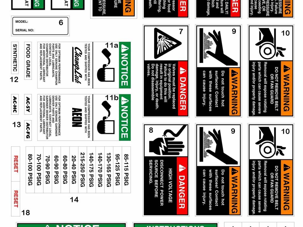
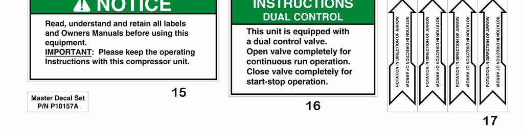
34 UNIT HAZARD DECALS 34

35 PUMP HAZARD DECALS F 35

 875-332 Fax (85)")


36 *F323VER6* *F323VER6* Copyright 200 Gardner Denver, Inc. Printed in U.S.A. Champion 30 North Euclid Avenue Princeton, Illinois 6356 USA Phone (85) Fax (85) Plants in Princeton, IL, and Manteca, CA Due to Champion s continuing product development program, specifications and materials are subject to change without notice or obligation
SINGLE STAGE, AIR COMPRESSORS & UNITS FEATURING BVA & BVAS PUMPS
 OPERATION/MAINTENANCE MANUAL & PARTS LIST SINGLE STAGE, AIR COMPRESSORS & UNITS FEATURING BVA & BVAS PUMPS THIS MANUAL CONTAINS IMPORTANT SAFETY INFORMATION AND SHOULD ALWAYS BE AVAILABLE TO THOSE PERSONNEL
McGUIRE AIR COMPRESSORS HP RECIPROCATING AIR COMPRESSORS. R-Series. McGUIRE AIR COMPRESSORS
 2 30 RECIPROCATING AIR COMPRESSORS R-Series CHAMPION R-SERIES Customized Solutions Unparalleled Performance A Winning Combination Champion compressors are proven units, known for their reliability over
INSTRUCTION MANUAL: Industrial Series Piston Air Compressor. Model Number: V Part Number: L001128KNA
 INSTRUCTION MANUAL: Industrial Series Piston Air Compressor Model Number: V8051-335 Part Number: L001128KNA Pump Model: LP335 K335 Motor: 5 HP / 1 PH Air Tank: 80 Gal Vertical 1830 W. 15 th St. Houston,
AIR COMPRESSOR OPERATING INSTRUCTION AND PARTS LIST
 AIR COMPRESSOR OPERATING INSTRUCTION AND PARTS LIST BELT TYPE IMPORTANT PLEASE MAKE CERTAIN THAT THE PERSON WHO IS TO USE THIS EQUIPMENT CAREFULLY READS AND UNDERSTANDS THESE INSTRUCTIONS BEFORE STARTING
Portable Electric/Gas Compressor Operating Instructions
 Portable Electric/Gas Compressor Operating Instructions NOTICE Carefully read this instruction manual before attempting to operate this compressor. MODEL # SERIAL # 1-800-551-2406 TABLE OF CONTENTS Safety
SPECIFICATIONS Horsepower: 1.5 HP Running Maximum PSI: 125 PSI Tank Capacity: 15 Gallons CFM: 6 40 PSI 5 90 PSI
 15 GALLON AIR COMPRESSOR Model: 7678 DO NOT RETURN TO STORE Please call 800-348-5004 for parts and service CALIFORNIA PROPOSITION 65 WARNING: You can create dust when you cut, sand, drill or grind materials
SPECIFICATIONS: Tank Size: 80 gallons PUMP RPMs: 1050 CFM: 40PSI; 90 PSI Max Pressure: 150 PSI Thermal overload protection
 5HP 80 GALLON TWO STAGE COMPRESSOR Models: 51866, 51870 CALIFORNIA PROPOSITION 65 WARNING: You can create dust when you cut, sand, drill or grind materials such as wood, paint, metal, concrete, cement,
5 25 HP RECIPROCATING AIR COMPRESSORS. Advantage
 5 25 RECIPROCATING AIR COMPRESSORS Advantage CHAMPION ADVANTAGE PROGRAM * Downtime is NOT an option Champion has the solution 2 Fully-Equipped Packages Available Immediately A Winning Combination Champion
PARTS MANUAL FOR TWO STAGE AIR COMPRESSOR
 PARTS MANUAL FOR TWO STAGE AIR COMPRESSOR SPECIFICATION CHART Model No. Horsepower Voltage-Single Phase Minimum Branch Circuit Requirement *Fuse Type Air Tank Capacity Approximate Cut-in Pressure Approximate
60 Series End-Mount Brake Instructions Standard Housing
 Bulletin No. BK4655 (04/18) 60 Series End-Mount Brake Instructions Standard Housing Read carefully before attempting to assemble, install, operate or maintain the product described. Protect yourself and
2 30 HP RECIPROCATING AIR COMPRESSORS. R-Series
 2 30 HP RECIPROCATING AIR COMPRESSORS R-Series CHAMPION R-SERIES Customized Solutions Unparalleled Performance A Winning Combination Champion compressors are proven units, known for their reliability over
2 30 HP RECIPROCATING AIR COMPRESSORS. R-Series
 2 30 HP RECIPROCATING AIR COMPRESSORS R-Series CHAMPION R-SERIES Customized Solutions Unparalleled Performance A Winning Combination Champion compressors are proven units, known for their reliability over
AIR COMPRESSOR INSTALLATION AND START-UP MANUAL. Table of Contents. Page# 1. INTRODUCTION 2. OWNER'S OBLIGATIONS 3. INSTALLATION AND START UP
 AIR COMPRESSOR INSTALLATION AND START-UP MANUAL Table of Contents Page# 1. INTRODUCTION 2. OWNER'S OBLIGATIONS 3. INSTALLATION AND START UP 4. INSTALLATION AND START UP / GAS 5. TROUBLE-SHOOTING GUIDE
McGUIRE AIR COMPRESSORS HP RECIPROCATING AIR COMPRESSORS. Advantage. McGUIRE AIR COMPRESSORS
 5 25 RECIPROCATING AIR COMPRESSORS Advantage CHAMPION ADVANTAGE PROGRAM * Downtime is NOT an option Champion has the solution 2 Fully-Equipped Packages Available Immediately A Winning Combination Champion
RolsplicerTM. Maintenance Manual And Illustrated Parts List
 RolsplicerTM Maintenance Manual And Illustrated Parts List List of Illustrations Figure Page. Rolsplicer 3 2. Roller Adjustment 4 3. Rolsplicer 6 4. Lid Hold Down Assembly 8 5. Automatic Lid Speed Adjustment
C T h e A d va n t a g e
 C The Advantage TABLE OF CONTENTS Introduction...1 Product Numbering System...1 Safety...2 Receiving and Inspection...2 Installation...2 Electrical...3 Parts Identification...7 Lubrication...9 Start-up...10
Iron Horse Air Compressor part breakdown - IHD6160V1 Item Description IHD6160V1 IHD6160V1 Call for the Customer Service Department.
 Iron Horse Air Compressor part breakdown - IHD6160V1 Item Description IHD6160V1 1 Compressor w/ Flywheel CC2065 2 Discharge Tube w/ Fittings TU-23-AL 3 Pressure Gauge PG200-2.5R 4 Air Receiver 60V20X48SPL
Routine Compressor Maintenance
 Establishing a regular, well-organized maintenance program and strictly following it is critical to maintaining the performance of a compressed air system. One person should be given the responsibility
Lubricator Gun: 10,000 psi (700 bar) Maximum Delivery Pressure when disconnected from Dispenser
 Maximum Delivery Pressure when disconnected from Dispenser") INSTRUCTIONS-PARTS LIST 30 455 INSTRUCTIONS This manual contains important warnings and information. READ AND KEEP FOR REFERENCE. Rev. C Supercedes B Hand-Operated Portable Grease Dispenser Buckshot Luber
INSTRUCTIONS-PARTS LIST 30 455 INSTRUCTIONS This manual contains important warnings and information. READ AND KEEP FOR REFERENCE. Rev. C Supercedes B Hand-Operated Portable Grease Dispenser Buckshot Luber
Thermal. Dimensions Torque Rotating. Rotating Capacity lb.ft. HPS/Min. Lb-Ft
 Bulletin No. BK4755 (11/07) 1-70 Series End-Mount Brake Instructions NEMA 2 Enclosure Read carefully before attempting to assemble, install, operate or maintain the product described. Protect yourself
DISCLAIMER: SPECIFICATIONS:
 5HP 80 GALLON TWO STAGE COMPRESSOR Models: 7654 CALIFORNIA PROPOSITION 65 WARNING: You can create dust when you cut, sand, drill or grind materials such as wood, paint, metal, concrete, cement, or other
Hydraulic Immediate Need Power Pack
 Safety, Operation, and Maintenance Manual WARNING Improper use of this tool can result in serious bodily injury This manual contains important information about product function and safety. Please read
READ AND SAVE THESE INSTRUCTIONS. High Velocity Restaurant-Duty Utility Set Belt Driven for Roof Mounting
 READ AND SAVE THESE INSTRUCTIONS INSTALLATION, OPERATING INSTRUCTIONS & PARTS MANUAL High Velocity Restaurant-Duty Utility Set Belt Driven for Roof Mounting Electrical wiring and connections should be
INSTALLATION AND OPERATING MANUAL
 Dated: May 10, 2001 INSTALLATION AND OPERATING MANUAL MODEL: T30-Y TURBOTWIN Engine Air Starter From Tech Development Inc AN96-425 6800 Poe Ave. Dayton OH 45414 Tel: (937) 898-9600 Fax: (937) 898-8431
Portable Oil Free Silent Series Compressor Operating Instructions
 Portable Oil Free Silent Series Compressor Operating Instructions NOTICE Carefully read this instruction manual before attempting to operate this compressor. MODEL # SERIAL # 1-800-551-2406 www.eaglecompressor.com
NECO Pumping Systems
 INSTALLATION OPERATION & MAINTENANCE INSTRUCTIONS For Your NECO Pumping Systems PACKAGED CIRCULATING SYSTEM THIS COMPLETELY ASSEMBLED, TESTED, PACKAGED CIRCULATING SYSTEM IS OF THE HIGHEST QUALITY AND
PARTS LIST FOR AIR COMPRESSORS AC-SH20-2 AC-SV20-2 ENGINE OIL GRADE: HONDA: SAE 10W-30. Below 40 F=SAE 10W-30 ENGINE OIL CAPACITY:
 PARTS LIST FOR AIR COMPRESSORS AC-SH20-2 AC-SV20-2 ENGINE OIL GRADE: HONDA: SAE 10W-30 VANGUARD: Above 40 F=SAE30 Below 40 F=SAE 10W-30 ENGINE OIL CAPACITY: HONDA: 37 oz. VANGUARD: 40 oz. MAXIMUM PRESSURE
INSTALLATION AND OPERATING MANUAL
 Publication T3-76, Rev. 1 Dated: May 9, 21 INSTALLATION AND OPERATING MANUAL MODEL: T3-I TURBOTWIN Engine Air Starter AN96-419 From Tech Development Inc 68 Poe Ave. Dayton OH 45414 Tel: (937) 898-96 Fax:
PARTS LIST T30 MODEL 2340 TWO STAGE INDUSTRIAL AIR COMPRESSOR
 S LIST T30 MODEL 2340 TWO STAGE INDUSTRIAL AIR COMPRESSOR Ingersoll-Rand Company Printed in U.S.A. Form SCD-749 August 1998 4 FIGURE 1. COMPRESSOR FRAME ASSEMBLY. 1-1 95033601 PLUG, PIPE - HEX HEAD -
READ AND SAVE THESE INSTRUCTIONS. Centrifugal Downblast Exhaust Fan Belt Driven for Roof & Wall Mounting
 READ AND SAVE THESE INSTRUCTIONS INSTALLATION, OPERATING INSTRUCTIONS & PARTS MANUAL Centrifugal Downblast Exhaust Fan Belt Driven for Roof & Wall Mounting Electrical wiring and connections should be done
AIR COMPRESSOR AC5161B AC5161BP. User Manual
 AIR COMPRESSOR AC5161B AC5161BP User Manual table of contents table of contents Safety 6 Safety Rules 7 Safety Warnings Overview 11 Basic Air Compressor Components Assembly 13 Assembling the Compressor
INSTRUCTIONS PARTS LIST This manual contains important warnings and information. READ AND RETAIN FOR REFERENCE
 INSTRUCTIONS PARTS LIST 308 493 This manual contains important warnings and information. READ AND RETAIN FOR REFERENCE Rev. A Second Gun Hose Kit 100 psi (6.9 bar) Maximum Working Pressure These kits include
Viscount I Hydraulic Motor and Displacement Pump
 INSTRUCTIONS-PARTS LIST 308 674 INSTRUCTIONS This manual contains important warnings and information. READ AND KEEP FOR REFERENCE. Rev. C Supersedes Rev. B Viscount I Hydraulic Motor and Displacement Pump
OWNER S MANUAL SELF-PRIMING PORTABLE UTILITY PUMP
 Model 54011-0 OWNER S MANUAL SELF-PRIMING PORTABLE UTILITY PUMP Questions, problems, missing parts? Before returning to the store call AQUAPRO Customer Service 8 a.m. - 5 p.m., EST, Monday-Friday 1-844-242-2475
6L Oil-less Air Compressor 53103
 6L Oil-less Air Compressor 53103 Operating Instructions Please read and save these instructions before attempting to assemble, install, operate or maintain the product. Protect yourself and others by observing
H.S. MACHINERY RING COMPRESSORS
 OPERATION & PARTS MANUAL Thank you for purchasing an H.S Machinery Limited Regenerative Blower. This product is manufactured under strict ISO-9001-2000 quality control guidelines to ensure your satisfaction.
END SUCTION CENTRIFUGAL PUMPS
 OWNERS GUIDE TO INSTALLATION AND OPERATION FW000 009 Supersedes 07 END SUCTION CENTRIFUGAL PUMPS READ THESE INSTRUCTIONS CAREFULLY Read these installation instructions in detail before installing your
Pump Owner s Manual. PLEASE! Read All Instructions Carefully Before Installing Pump
 Pump Owner s Manual PLEASE! Read All Instructions Carefully Before Installing Pump Guarantee Associate Engineering Corporation warrants that pumps purchased from them will be free of defects in material
Electric Compressors US7580V B6000 FS002 MM36H675 SV25200 PS10M FIB02DC CV22 DT023 BG31184 BA67(2) S2AK61H
 S2AK61H") Electric Compressors 10 09 01 02 03 08 04 05 06 07 Illustration Part Description Number US660V US580V 1 Compressor B3800 T29S 2 Air Filter 2281000 4981000 3 Electric Motor M182711 M182703 4 Safety Valve
Electric Compressors 10 09 01 02 03 08 04 05 06 07 Illustration Part Description Number US660V US580V 1 Compressor B3800 T29S 2 Air Filter 2281000 4981000 3 Electric Motor M182711 M182703 4 Safety Valve
TWO-STAGE HYDRAULIC PUMP. RWP55-IBT-Air
 ORIGINAL INSTRUCTIONS Form No.1000458 5 SPX Corporation 5885 11th Street Rockford, IL 61109-3699 USA Tech. Services: (800) 477-8326 Fax: (800) 765-8326 Order Entry: (800) 541-1418 Fax: (800) 288-7031 Internet
PRODUCT NUMBERING SYSTEM SERIES PHASE. HD: Heavy Duty (15,000+ hour life) SD: Standard Duty (5,000+ hour life) LD: Light Duty (2,000+ hour life)
 SD: Standard Duty (5,000+ hour life) LD: Light Duty (2,000+ hour life)") TABLE OF CONTENTS Product Numbering System...1 Safety...2 Receiving and Inspection...2 Installation...2 Electrical...3 Parts Identification...7 Lubrication...9 INTRODUCTION The compressor you have purchased
TABLE OF CONTENTS Product Numbering System...1 Safety...2 Receiving and Inspection...2 Installation...2 Electrical...3 Parts Identification...7 Lubrication...9 INTRODUCTION The compressor you have purchased
TECHNICAL SERVICE MANUAL
 Electronic copies of the most current TSM issue can be found on the Viking Pump website at www.vikingpump.com TECHNICAL SERVICE MANUAL industrial heavy duty motor speed pumps SERIES 4076 AND 4176 SIZES
LUBRICATOR GUN INSTRUCTIONS-PARTS LIST. 10,000 psi (700 bar) Maximum Delivery Pressure. Detachable-type
 Maximum Delivery Pressure. Detachable-type") INSTRUCTIONS-PARTS LIST 306 460 INSTRUCTIONS This manual contains important warnings and information. READ AND KEEP FOR REFERENCE. Rev. E Supercedes D Detachable-type LUBRICATOR GUN 10,000 psi (700 bar)
INSTRUCTIONS-PARTS LIST 306 460 INSTRUCTIONS This manual contains important warnings and information. READ AND KEEP FOR REFERENCE. Rev. E Supercedes D Detachable-type LUBRICATOR GUN 10,000 psi (700 bar)
proven dependability.
 R & PL SERIES 1.5 5 Horsepower Reciprocating Air ressors proven design. proven dependability. At Champion, air compressor systems are our only products. We know and understand the application of our products
PARTS LIST FOR AIR COMPRESSORS 15 Hp Industrial Duplex. Copyright 2009, Mi-T-M Corporation
 PARTS LIST FOR AIR COMPRESSORS 15 Hp Industrial Duplex 1 This Parts Listing has been compiled for your benefit. You can be assured your Mi-T-M Gasoline Air Compressor was constructed and designed with
INSTALLATION AND OPERATING
 Publication T5-704, Rev. 4 Dated: November 1, 2006 INSTALLATION AND OPERATING MANUAL T50-P TURBOTWIN Engine Air Starter AN 99-448 TABLE OF CONTENTS Section Subject Page 1.0 General Information. 1 2.0 Orientation
2SHE Series Direct-Drive Shutter Fans
 Operational Instruction and Parts Manual Item #: 481810 Rev Date: 101414 2SHE Series Direct-Drive Shutter Fans Fantech, Inc. and Systemair Mfg. certify that the ventilators shown herein are licensed to
HP RECIPROCATING AIR COMPRESSORS. Engine Driven
 9.1 22.5 HP RECIPROCATING AIR COMPRESSORS Engine Driven CHAMPION ENGINE DRIVEN Service trucks, contractors, and farmers all need a reliable compressor that will be suitable for the tools they will use.
MAINTENANCE MANUAL FOR THERMOSTATIC TEMPERATURE REGULATING VALVE TRAC STYLE P
 MANUAL NUMBER P-EFS-1 MAINTENANCE MANUAL FOR THERMOSTATIC TEMPERATURE REGULATING VALVE TRAC STYLE P TRAC Regulator Company Inc. 160 South Terrace Avenue Mount Vernon, New York USA 10550-2408 Phone: (914)
COLT 2310, 2510, AND 2712 COM PACT TRACTORS CHAPTER 9 TROUBLESHOOTING AND ANALYSIS
 COLT 2310, 2510, AND 2712 COM PACT TRACTORS CHAPTER 9 TROUBLESHOOTING AND ANALYSIS 9-A-1 UPON RECEIVING ANENGINE FORRE- PAIR. Learn the history of the unit from the customer. While the customer is present
PRO ES Test Fixture, High Voltage Test Probe, & KV Meter
 INSTRUCTIONS PARTS LIST 308 217 This manual contains important warnings and information. READ AND RETAIN FOR REFERENCE Rev. B Supersedes A PRO ES Test Fixture, High Voltage Test Probe, & KV Meter To Test
Pneumatic Cylinder 14 Bore X 22 Stroke Part No. R (Formerly P )
") Pneumatic Cylinder 14 Bore X 22 Stroke Part No. R434001268 (Formerly P -193419-00003) Service Information INSTALLATION Before installing this cylinder, all air lines in the system should be blown clean
Pneumatic Cylinder 14 Bore X 22 Stroke Part No. R434001268 (Formerly P -193419-00003) Service Information INSTALLATION Before installing this cylinder, all air lines in the system should be blown clean
Hydraulic PTO Flow Device
 Safety, Operation, and Maintenance Manual WARNING Improper use of this tool can result in serious bodily injury This manual contains important information about product function and safety. Please read
OWNER/OPERATOR MANUAL. Airmotor effective dia. in. 2.5
 MODELS 282050, 282716 & 283513 AIR OPERATED CHASSIS PUMP SERIES A OWNER/OPERATOR MANUAL SPECIFICATIONS Airmotor effective dia. in. 2.5 Airinlet Material outlet 1/4 NPTF 1/4 NPTF Liquid to Air Pressure
SHALLOW WELL JET PUMP
 SHALLOW WELL JET PUMP MODEL FJ05S 1/2 HP flintandwalling.com ATTACH YOUR RECEIPT HERE Serial Number Purchase Date 1 FW1642 B TABLE OF CONTENTS Product Specifications...2 Safety Information...2 Package
Pro Shot Grease Dispense Valve
 Instructions Parts List Pro Shot Grease Dispense Valve 309032J For high pressure grease dispense. 8000 psi (55 MPa, 552 bar) Maximum Working Pressure Model No. 242055, Series B, 1/4 npt Fluid Inlet Model
DIAMOND CONCRETE SAW MODEL CC1800XL P R O D U C T S OPERATOR S MANUAL. February Part #
 DIAMOND P R O D U C T S OPERATOR S MANUAL CONCRETE SAW MODEL CC1800XL February 2007 Part #1801038 Intentionally Blank GENERAL SAFETY WARNINGS AND PRECAUTIONS PERSONAL SAFETY Read and understand all operating
Series CP200. Triplex Ceramic Plunger Pump Operating Instructions/ Repair and Service Manual. For Models: CP218 CP219 CP220 CP230
 Series CP200 Triplex Ceramic Plunger Pump Operating Instructions/ Repair and Service Manual For Models: CP218 CP219 CP220 CP230 Updated 10/02 Contents: Installation Instructions: page 2 Pump Specifications:
PARTS LIST FOR AIR COMPRESSOR/GENERATOR/WELDER AGW-SH22-20M
 PARTS LIST FOR AIR COMPRESSOR/GENERATOR/WELDER AGW-SH22-20M ENGINE: HONDA ENGINE OIL GRADE: SAE 10W-30 ENGINE OIL CAPACITY: 67.6 oz. MAXIMUM PRESSURE: COMPRESSOR OIL GRADE: COMPRESSOR OIL CAPACITY: 175
Air / Hydraulic Pump
 Form No. 538016 Parts List & Operating Instructions for: 2510A Original Instructions Air / Hydraulic Pump Maximum Capacity: 690 bar (10,000 psi) Description: The 2510A air/hydraulic pump is designed to
MODEL HP MAXIMUM RECEIVER MOTOR DIMENSIONS WEIGHT 100 PSI RATED PSI CAPACITY L-W-H (ins) (lbs) Toll Free
 (lbs) Toll Free") PUMP & COMPRESSOR LTD. Rugged compressor with cast iron cylinders V design minimizes vibration, improves cooling and extends compressor life Individual and removable cylinders for smoother and cooler operation
PUMP & COMPRESSOR LTD. Rugged compressor with cast iron cylinders V design minimizes vibration, improves cooling and extends compressor life Individual and removable cylinders for smoother and cooler operation
Voltmaster Centrifugal Trash Pumps
 Voltmaster Centrifugal Trash Pumps Model TSP2, TSP3 and TSP4 Owner s Manual February 2011 Table of Contents 1 Introduction............................ 1 1.1 Read before using..................... 1 1.2
Operating Instructions - Electric Pow'r-Riser Models
 ADivisionOf Templeton, Kenly& Co., Inc. Operating Instructions - Electric Pow'r-Riser Models Table of Contents 1.0 Recieving Instructions 2.0 Safety 3.0 Specifications 4.0 Initial Installation Before Operating
ORIGINAL INSTRUCTIONS G715A. Pneumatic-hydraulic Riveter E. Warner Ave Santa Ana, CA
 ORIGINAL INSTRUCTIONS G715A Pneumatic-hydraulic Riveter 1224 E. Warner Ave Santa Ana, CA 92705 www.cherryaerospace.com DESCRIPTION The Cherry G715A Pneumatic-Hydraulic Riveter is designed specifically
CONTENTS. VIKING PUMP, INC. A Unit of IDEX Corporation Cedar Falls, IA USA SECTION TSM 710.1
 TECHNICAL SERVICE MANUAL industrial heavy duty motor speed pumps SERIES 4076 AND 4176 SIZES hle, ate and ale SECTION TSM 710.1 PAGE 1 of 8 ISSUE B CONTENTS Introduction....................... 1 Safety
Model LP200, LP250 & LP250W-MT
 Triplex Ceramic Plunger Pump Operating Instructions/ Repair and Service Manual Model LP200, LP250 & LP250W-MT Updated 5/02 Contents: Installation Instructions: page 2 LP200 Specifications: page 3 Exploded
Pneumatic Cylinder 14 Bore X 21 Stroke Part No. P Replaces Part No. P
 Pneumatic Cylinder 14 Bore X 21 Stroke Part No. P -322908-00000 Replaces Part No. P-191067-00000 Service Information WARNING: INSTALLATION AND MOUNTING The user of these devices must conform to all applicable
EWS FLUID END PARTS LIST
 GARDNER DENVER Rev C September 2005 WELL SERVICING PUMP MODEL C-2500 QUINTUPLEX EWS FLUID END PARTS LIST ECN 1027623 C-2500 WELL SERVICING PUMP MAINTAIN PUMP RELIABILITY AND PERFORMANCE WITH GENUINE GARDNER
UNPACKING SAFETY GUIDELINES GENERAL SAFETY INFORMATION. Operating Instructions & Maintenance Manual
 Please read and save this Repair Parts Manual. Read this manual and the General Operating Instructions carefully before attempting to assemble, install, operate or maintain the product described. Protect
Solutions beyond products...
 ORIGINAL INSTRUCTIONS IH102C Installation, Operation & Maintenance Manual Model B177 External Automatic Bypass Valve Model B177 External Automatic Bypass Valve Warning: (1) Periodic inspection and maintenance
proven dependability.
 R & PL SERIES 1.530 Horsepower Reciprocating Air Compressors proven design. proven dependability. At Champion, air compressor systems are our only products. We know and understand the application of our
Jet Fans. Instruction Manual READ AND SAVE THESE INSTRUCTIONS WARRANTY
 Jet Fans Instruction Manual READ AND SAVE THESE INSTRUCTIONS WARRANTY All Leader Fan products are guaranteed to be free from defects of workmanship or material and to function satisfactorily when properly
Operating instructions Form no safety definitions
 Operating instructions Form no. 1000437 safety definitions safety symbols are used to identify any action or lack of action that can cause personal injury. Your reading and understanding of these safety
See Warranty on page 6 for important information about commercial use of this product.
 See Warranty on page 6 for important information about commercial use of this product. Operating Instructions WL6000 Series Please read and save these instructions. Read carefully before attempting to
Owner s Manual GLASSLINED PUMP TANK
 Owner s Manual GLASSLINED PUMP TANK ANSI/NSF 61 Annex G Thank You for purchasing a pump tank. Properly installed and maintained, it should give you years of trouble free service. If you should decide that
T1-Titanium Non-HVLP Spray Gun
 T1-Titanium Non-HVLP Spray Gun THE SPRAY GUN PEOPLE FOR PRODUCT INFORMATION CALL: 1-800-742-7731 Important Safety Instructions Read all warnings and instructions in this manual. Save these instructions.
3 30 HP RECIPROCATING AIR COMPRESSOR. PL-Series
 3 30 HP RECIPROCATING AIR COMPRESSOR PL-Series GARDNER DENVER PL-SERIES Experience Proven Results with Gardner Denver the Leader in Durability, Reliability & Efficiency 2 Customized Solutions Proven Dependability
Full View Flow Indicator
 Full View Flow Indicator Threaded and Flanged Process Connection Installation / Operation / Maintenance Manual P.O. Box 1116 Twinsburg, OH 44087 Phone: 330/405-3040 Fax: 330/405-3070 E-mail: view@ljstar.com
PRODUCT NUMBERING SYSTEM SERIES PHASE. 1: Single Phase 3: Three Phase
 TABLE OF CONTENTS Product Numbering System and Specifications... Safety... Receiving and Inspection... Installation... Electrical...6 Start-up...7 INTRODUCTION The compressor you have purchased is a combination
Inertia of Rotating Parts Lb-Ft 2. Thermal Capacity HPS/Min.*
 60 Series Double C Brake Instructions NEMA 4X Washdown Housing Read carefully before attempting to assemble, install, operate or maintain the product described. Protect yourself and others by observing
Premium Series Grease Dispensing Handle One and Two Piece Body Styles
 Service Bulletin SB3018 Rev. A 3/07 Premium Series Grease Dispensing Handle One and Two Piece Body Styles Models: Handle w/swivel and 36" Whip Hose 020 Handle w/swivel and 18" Whip Hose 025 Handle w/swivel
POWER END PARTS LIST
 GARDNER DENVER 302WPD997 Rev B April 2008 WELL SERVICING PUMP MODEL GD-600 POWER END PARTS LIST ECN 1040704 GD-600 WELL SERVICING PUMP MAINTAIN PUMP RELIABILITY AND PERFORMANCE WITH GENUINE GARDNER DENVER
Air Operated Double Diaphragm Pump. M-Pump ½ Metallic Non Metallic Pump INSTALLATION, OPERATION & MAINTENANCE MANUAL
 Air Operated Double Diaphragm Pump M-Pump ½ Metallic Non Metallic Pump INSTALLATION, OPERATION & MAINTENANCE MANUAL 0.5 I.O.M rev 05. 12/2015 INDEX Title Section Introduction.1 Safety.2 Warranty, General
WALKIE HIGH LIFT HYDRAULIC SYSTEM
 WALKIE HIGH LIFT HYDRAULIC SYSTEM W30-40ZA [B453]; W20-30ZR [B455]; W25-30-40ZC [B454] PART NO. 1524251 2000 SRM 1025 SAFETY PRECAUTIONS MAINTENANCE AND REPAIR When lifting parts or assemblies, make sure
STAR STOP SHALLOW WELL JET PUMP
 SHALLOW WELL JET PUMP MODEL SJ0S / HP STAR starwatersystems.com STOP Questions, problems, missing parts? Before returning to your retailer, call our customer service department at -800-7-0, 7:0 a.m. -
Spray Nozzle Adapters
 INSTRUCTIONS-PARTS LIST 306 788 INSTRUCTIONS This manual contains important warnings and information. READ AND KEEP FOR REFERENCE. First choice when quality counts. Rev. G Supersedes Rev. F DIRECTIONAL
TP300 INDUSTRIAL TRASH PUMP OPERATOR S MANUAL
 TP300 INDUSTRIAL TRASH PUMP OPERATOR S MANUAL IT IS EXTREMELY IMPORTANT TO READ AND UNDERSTAND THE ENTIRE CONTENTS OF THIS OPERATOR S MANUAL BEFORE ATTEMPTING TO OPERATE THE PRODUCT. THIS EQUIPMENT IS
P SERIES PUMPS. 18mm Versions Nickle-Aluminum Bronze Models: P , P , P , P , P , P , P
 P200-3100 SERIES PUMPS 18mm Versions Nickle-Aluminum Bronze Models: P217-3100, P218-3100, P219-3100, P220-3100, P221-3100, P227-3100, P230-3100 Triplex Ceramic Plunger Pump Operating Instructions/ Repair
ORIGINAL INSTRUCTIONS G700
 ORIGINAL INSTRUCTIONS G700 HYDRO-SHIFT CHERRYLOCK RIVETER 1224 East Warner Ave, Santa Ana, Ca 92705 Tel: 1-714-545-5511 Fax: 1-714-850-6093 www.cherryaerospace.com G700 HYDRO-SHIFT INSTRUCTIONS TABLE OF
6 Litre Oil-Less Air Compressor
 Operator s Manual 6 Litre Oil-Less Air Compressor WARNING! Before using this appliance, read the Operator s manual and follow all its safety rules and instructions. SPECIFICATION HWKAC1 1.1 kw / 1.5 HP
BCFS Belt Driven Centrifugal Filtered Supply Fans
 BCFS Belt Driven Centrifugal Filtered Supply Fans INSTALLATION, OPERATION & MAINTENANCE MANUAL IM-4300 August 2014 Throughout this manual, there are a number of HAZARD S that must be read and adhered to
READ AND SAVE THESE INSTRUCTIONS. Centrifugal Upblast Exhaust Fan (Standard & High Pressure Exhaust) Belt Driven for Roof & Wall Mounting
 Belt Driven for Roof & Wall Mounting") READ AND SAVE THESE INSTRUCTIONS INSTALLATION, OPERATING INSTRUCTIONS & PARTS MANUAL Centrifugal Upblast Exhaust Fan (Standard & High Pressure Exhaust) Belt Driven for Roof & Wall Mounting Electrical wiring
READ AND SAVE THESE INSTRUCTIONS INSTALLATION, OPERATING INSTRUCTIONS & PARTS MANUAL Centrifugal Upblast Exhaust Fan (Standard & High Pressure Exhaust) Belt Driven for Roof & Wall Mounting Electrical wiring
Repair Instructions and Parts List
 Repair Instructions and Parts List 309887B Manufactured by Pressure Washers INSTRUCTIONS This manual contains important warnings and information. READ AND KEEP FOR REFERENCE. APS2730H Model 246798, Series
Val-Matic Air / Oil Hydraulic Panel Pump Control System. Operation, Maintenance and Installation Manual
 Manual No. 5AOP-OM1-2 Val-Matic Air / Oil Hydraulic Panel Pump Control System Operation, Maintenance and Installation Manual INTRODUCTION... 1 RECEIVING AND STORAGE... 1 DESCRIPTION OF OPERATION... 1 INSTALLATION...
Hydraulic Wheel Dolly
 Hydraulic Wheel Dolly Operating Instructions & Parts Manual Model Number HW93766 Capacity 3/4 Ton Made in the U.S.A. This is the safety alert symbol. It is used to alert you to potential personal injury
2" - 24" OS Series Butterfly Valves. Operation and Maintenance Manual. Job Name: Contractor: Date:
 s Operation and Maintenance Manual Job Name: Contractor: Date: Document #: IOM Revision Date: 10/2/2016 SAFETY MESSAGES All safety messages in the instructions are flagged with an exclamation symbol and
High Velocity Series Air Curtains
 INSTALLATION & OPERATING INSTRUCTIONS & PARTS MANUAL FOR ALL 208-230/480 VOLT 3 PHASE. MOTOR MODELS High Velocity Series Air Curtains READ CAREFULLY BEFORE ATTEMPTING TO ASSEMBLE, INSTALL, OPERATE, OR
D Instructions/Parts. Siphon Feed Detail Spray Gun D
 Instructions/Parts D-5-55 Siphon Feed Detail Spray Gun FOR PRODUCT INFORMATION CALL: 1-800-742-7731 309991D Important Safety Instructions Read all warnings and instructions in this manual. Save these instructions.
APCO CRF-100A RUBBER FLAPPER SWING CHECK VALVES
 APCO CRF-100A RUBBER FLAPPER SWING CHECK VALVES Instruction D12043 June 2016 DeZURIK Instructions These instructions provide installation, operation and maintenance information for APCO CRF-100A Rubber
Engine Driven. McGUIRE AIR COMPRESSORS McGUIRE AIR COMPRESSORS Service Fleets. Automotive. Construction.
 Engine Driven Two Stage Reciprocating Air CompreSSoRS 8 23 HP Service Fleets Automotive Construction Agricultural Tank Mounted Gas Driven 2 Champion is the leader in manufacturing dependable compressed