CUSTOMER S MANUAL. Coil models FV,FK,FH,FC,FD,FP,FS TV,TK,TC,TD
|
|
|
- Osborne McCoy
- 5 years ago
- Views:
Transcription


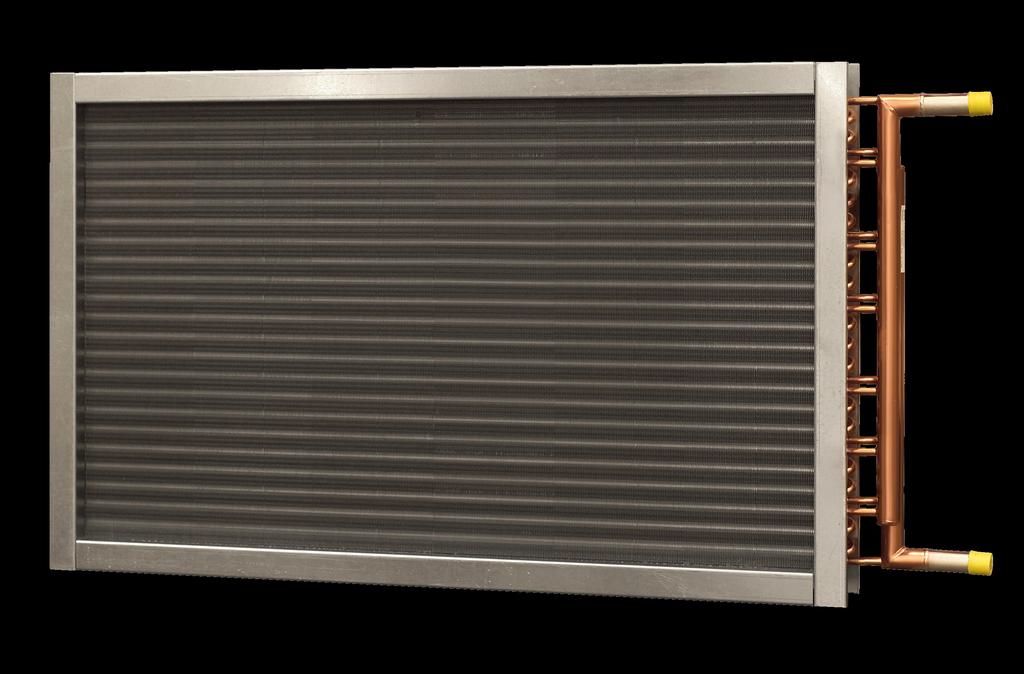

1 CUSTOMER S MANUAL Coil models FV,FK,FH,FC,FD,FP,FS TV,TK,TC,TD 1 Version: 8. Jui 2016
2 INDEX SIDE RECEPTION MANUAL On Receipt of shipment... 3 ASSEMBLING MANUAL... 4 USER S MANUAL... 7 Startup.. 7 MAINTENANCE MANUAL. 7 Cleaning... 7 Wear and Tear SAFETY PRECAUTIONS Repair
3 RECEPTION MANUAL In general Your coil our product is made with great care utilizing only the best material. If you follow this manual, your coil should be ensured a long and effective operation. On Receipt of Shipment Verify that the shipment is without damage. This verification includes the packing. If the shipment is damaged: Mark the damage in the consignment note. You can now substantiate a possible complain. This procedure is necessary for possible recourse against the carrier. If possible, photograph the shipment, preferably while still in the van. Inform the local representative of EVAPCO Air Solutions a/s or the factory about the circumstances for the damage. With substantial damage the shipment is refused. The damage has to be marked in the consignment note. This note is then given to the carrier with orders to return the shipment to the factory. As a minimum for further transportation always use packing methods similar to those used by EVAPCO Air Solutions. The shipment is removed from the van in the following way: (For shipments where a forklift truck or crane is necessary) Ensure that the crane operator and/or the truck driver lift the unit securely. Always consider the weight of the coil with regard to crane, forklift, etc. Tubes and return bends are never to be used for lifting and you should always be careful, when moving the coil. Remove the packing and verify that no damage, previously hidden, has occurred. Here can be added that slightly dented fins normally can be repaired easily. You can, as habitual costumer, have advantage of buying a fin straighten tool, which is a useful tool for your fitter. Dented or slightly damaged tubes are only to be repaired by a qualified fitter. If the damage of the tubes cannot be repaired by your fitter contact your local EVAPCO Air Solutions representative about returning the shipment to the factory. Be aware that you according to insurance procedures only have 1 working week to forward your damage complaint, if the damage has not been marked in the consignment note. 3
4 ASSEMBLING MANUAL Take care to protect all parts of the unit, including the tube connections, and avoid denting the fins, when moving the coil. If care is not taken, there is a risk of damages not immediately noticeable, which as a result do not come to your knowledge until after installation. The coil must be placed with the coil tubes completely horizontal to ensure an optimum operation. The coil should be placed in such way that free access and discharge of airflow are possible at all times. Connecting the Liquid/Air Coil to the Pipe Work: Each unit is marked with arrows to show inlet and outlet. When connecting the coil to the pipe work the following is to be considered. Take care to avoid tension when connecting pipe work. Vibrations and pulses can damage the coil. The inlet and outlet tubes of the coil must not carry the rest of the pipe work. If necessary use flexible connectors. When tightening the threaded headers, always use torque wrenched opposite the tightening direction, to avoid damage to the tubes. If possible the system is filled, from the bottom, as this allows for better air vent. Take care that the system is completely emptied for air. If air bubbles occur in the system, the heat transfer is not optimum. If the headers have plugs for air vent and drainage valves, do not use these plugs for air venting or draining the system, as leaks might occur, when retightening the plugs. Use valves designed for air venting and drainage. Be particularly aware of temperatures around zero and below, as these temperatures could mean danger of breakage due to frost in the tubes of the coil. Always consider the temperature when choosing a brine mixture. To avoid damages the coil should be emptied completely for fluid. To ensure the complete emptying of the coil, compressed air should be used, through the air ventilation connection until the coil is empty. 4
5 If the duct mounted coil has a drip tray, please follow the instructions to dimensio the water trap. Duct Mounted Coil Positive air pressure X Y Air direction Y = P S / mm X = 50 mm (Minimum) P S Duct Press. P S Atmospheric Press. P O Negative air pressure X Y P O P S & P O in N/m 2 (Pascal) X = P S / mm Y = X / 2 mm (Minimum) 5
6 Connecting the Liquid/Hot Gas Coil to the Pipe Work: When connecting liquid and hot gas lines to the coil, the following should be considered. Take care to avoid tension when connecting gas and liquid lines. Vibrations and pulses can damage the coil. The inlet and outlet tubes of the coil must not carry the rest of the pipe work. If necessary use flexible connectors. Before assembly, the protective gas in the coil (overpressure of approx. 1 Bar) has to be let out. When no more outlet of gas can be heard, the header/bottom caps can be removed from the tubes. Use a tube cutter and never a saw. Never braze or weld on the coil, as long as pressure still exists in the connecting system and the coil contains gas. Ensure that the coil is disconnected from the rest of the system and evacuate the coil before working on it. If the cooling coil has a drip tray follow the same instructions as for the Liquid/Air coil. (According drawings above). Connecting a steam coil to the Pipe Work: When installing a steam coil into a piping system, the following should be considered. When installing a steam coil into a piping system, ensure that condensate can be drained and always use steam traps on each condensate connection. Always ensure that the steam is dry, as humid steam can cause water hammering. To help avoiding this, insulation of the steam pipes may be advisable. Vibrations and pulses can damage the coil and it may therefore be advisable to install vibration dampers in the piping system which can absorb a large majority of these vibrations. It is highly recommended that steam coils are installed with coil tubes in a vertical position. If this is not possible coils must be installed in a way which allows condensate to be drained away from the coil to steam traps. The inlet- and outlet tubes (manifolds) of the coil must not carry the connecting piping system which must be carried by supports or similar devises. Due to high temperatures it is very important that coil tubes can expand freely during operation. This means that manifolds under no circumstances must be fixated. If this happens it is very likely that the coil will break down. When starting the steam system, steam valve has to be opened slowly to warm up the hole system before being taken in operation, to avoid stress tension and water hammering. If you have any doubts, please contact your local EVAPCO Air Solutions representative or the factory for advice. 6
7 USER S MANUAL Start: After secure placement and connection of pipe work, please verify that the rest of the pipe work/the pumps do not transfer any pulses and vibrations to the coil. Check for leaks! If possible, measure for control the performance of the coil and file these measurements. These measurements can be used to control the performance reduction due to fouling of fins and the cleaning frequency can be planned. MAINTENANCE MANUAL Cleaning: It is essential to understand that fouled or dirty fins reduce the heat transfer substantially. After operation for some time, please check for fouling of the fins. Use a flash light to light between the fins to establish the accumulations of dust and smudge. Furthermore check whether these accumulations have resulted in a reduction of airflow and/or performance compared to a clean unit. Dry dust can normally be removed by means of compressed air (against the direction of air in the coil) or by means of a suitable industrial vacuum cleaner or use a soft brush. Sweep along the fins and under no circumstances across the fins. Moist or sticky smudges or grease should to be removed by means of hot water or steam jet cleaning appliances (against the air direction). Keep the jet of the cleaning appliance at an angle of no more than 15 from vertical position, to avoid bending the edges of the fins. Under no circumstances use organic solvents and cleaning products!!!! Please contact the producer of the cleaning products to clarify which products you can use without damaging the components of the coil. If you have any doubt, please contact your local EVAPCO Air Solutions representative or the factory. Mechanical cleaning with hard objects might damage the tubes, fins etc. of the coil!!! Wear and Tear: As a rule beware of corrosion of metals, check for this when cleaning the unit. 7
8 SAFETY PRECAUTIONS Use only liquids specified for the coil. Be aware of the pressure in the coil. Too high a pressure might result in damages!! Be aware that the heat exchanger as standard is delivered WITHOUT any kind of security equipment. Connection of the coil therefore demands, that security equipment is mounted on the system!! Repair: If the coil has to be repaired, certain rules must be followed. It is not advisable to leave objects on the fins or clogged between the fins after repairs, due to reduction of performance, etc. Never braze or weld on the coil, as long as pressure still exists in the system and the coil contains fluid. Ensure that the coil is disconnected from the rest of the system and emptied for fluid before working on it. 8
Standard Service / Installation / Operation Manual Type W & P Water / Glycol Heat Transfer Coils
 Standard Service / Installation / Operation Manual Type W & P Water / Glycol Heat Transfer Coils Please consult your local representative or the factory for warranty issues. July 2017 DRS Marlo Coil Customer
Daikin Steam Coils. Installation and Maintenance Manual IM 901. Types HI-F5, HI-F8, & E-F5. Group: Applied Air. Part Number: IM 901
 Installation and Maintenance Manual IM 901 Daikin Steam Coils Group: Applied Air Part Number: IM 901 Date: February 2008 Types HI-F5, HI-F8, & E-F5 2008 Daikin Applied Contents Introduction... 3 General
Cooling system components, removing and installing
 Page 1 of 40 19-1 Cooling system components, removing and installing WARNING! The cooling system is pressurized when the engine is warm. When opening the expansion tank, wear gloves and other appropriate
Fluid Coil Installation, Operation and Maintenance
 Bulletin FCO&I 001 REV A Fluid Coil Installation, Operation and Maintenance Monika Hewlett Packard Company [Pick the date] FLUID COIL INSTALLATION, OPERATION & MAINTENANCE GUIDELINES Fluid Coil Installation,
READ AND SAVE THESE INSTRUCTIONS
 READ AND SAVE THESE INSTRUCTIONS Part #469003 Model Vektor -H Installation Operation and Maintenance Manual for Vektor-H Laboratory Exhaust System Receiving Greenheck model Vektor-H fans are thoroughly
BOILER FEED SYSTEM OPERATION AND MAINTENANCE MANUAL
 BOILER FEED SYSTEM OPERATION AND MAINTENANCE MANUAL IMPORTANT These instructions are intended as a guide for the Installing Contractor and as a reference for the Operator, Owner and Serviceman. RETAIN
Cooling system components, removing and installing
 19-1 Cooling system components, removing and installing Note: When the engine is warm the cooling system is under pressure. If necessary release pressure before starting repair work. Hoses are secured
I & M 8000 Series. Ideal Installation Schematic. Preferred Installation. Trouble Shooting
 I & M 8000 Series 3170 Wasson Road Cincinnati, OH 45209 USA Phone 513-533-5600 Fax 513-871-0105 lowflow@richardsind.com www.lowflowvalve.com Installation & Maintenance Instructions for 8000 Series Low
WELDING FUME EXHAUSTERS & ARMS
 WELDING FUME EXHAUSTERS & ARMS The Ace 75 Series is our flexible and effective line of welding fume exhausters and extraction arms for shops that elect to exhaust their weld fumes outdoors instead of through
Daily Manual for Operators. RAVO 5-Series
 Daily Manual for Operators RAVO 5-Series 1 Adjustment + inspection suction mouth Page 1 2 Adjustment + inspection brush and water system Page 3 3 Optimum RPM during sweeping Page 6 4 Optimum use of the
D-Series Blowers and Exhausters
 Operation and Maintenance Manual D-Series MONOXIVENT - SOURCE CAPTURE SYSTEMS - info@ Oct. - 2015 MONOXVENT BLOWERS AND EXHAUSTERS D05-1 D05-3 D10-1 D10-3 D15-1 D15-3 D20-1 D20-3 D30-1 D30-3 ½ HP TEFC
User s Manual D-Series Blowers and Exhausters
 User s Manual D-Series Blowers and Exhausters D05-1 ½ HP TEFC 115/230 VOLTS, 1 PH D05-3 ½ HP TEFC 208/230/460 VOLTS, 3 PH D10-1 1 HP TEFC 115/230 VOLTS, 1 PH D10-3 1 HP TEFC 208/230/460 VOLTS, 3 PH D15-1
Volkswagen New Beetle 1.8 Liter 4-Cyl. 5V Turbo OBD II Engine Mechanical 19 Engine-Cooling system (Page GR-19)
") 19 Engine-Cooling system (Page GR-19) Cooling system components, removing and installing Continued coolant circulation pump (V51), checking Coolant hose connection diagram Coolant pump, removing and installing
19 Engine-Cooling system (Page GR-19) Cooling system components, removing and installing Continued coolant circulation pump (V51), checking Coolant hose connection diagram Coolant pump, removing and installing
TM-1620 OPERATING INSTRUCTIONS AND OWNERS MANUAL
 TM-1620 OPERATING INSTRUCTIONS AND OWNERS MANUAL tracopackaging.com 800-284-WRAP 620 SOUTH 1325 WEST OREM, UT. PHONE 800-284-WRAP (9727) IMPORTANT: READ ALL INSTRUCTIONS BEFORE OPERATING EQUIPMENT Your
Manufacturer Kakogawa, Japan DC5S
 ISO 9001/ ISO 14001 Manufacturer Kakogawa, Japan is approved by LRQA LTD. to ISO 9001/14001 Cyclone Separator Trap DC5S Copyright 2015 by TLV Co., Ltd. All rights reserved 1 Contents Introduction... 1
INSTALLATION MANUAL TBH/TBV BELT DRIVE BLOWER-COIL UNITS HORIZONTAL. Redefine your comfort zone.
 INSTALLATION MANUAL TBH/TBV BELT DRIVE BLOWER-COIL UNITS HORIZONTAL BELT DRIVE BLOWER-COIL UNITS TBH/TBV, HORIZONTAL Table of Contents Safety Symbols & Considerations...3 Return / Exhaust Casing Extension...4
Gauges, Sight Glasses and Vacuum Breakers
 Gauges, Sight Glasses and Vacuum Breakers Gauges, Sight Glasses and Vacuum Breakers Gauges Pressure gauges Pressure gauges should be installed in at least the following situations: Upstream of a pressure
Crankcase Ventilation Manager (CVM) Installation Instructions
 Installation Instructions") Crankcase Ventilation Manager (CVM) Installation Instructions CVM280 CVM424 Parts List E D C B A A B C D E Part Description No. Included A Shell 1 B Collar 1 C *O-Ring 1 D *Element 1 E Head 1 Part Number
Crankcase Ventilation Manager (CVM) Installation Instructions CVM280 CVM424 Parts List E D C B A A B C D E Part Description No. Included A Shell 1 B Collar 1 C *O-Ring 1 D *Element 1 E Head 1 Part Number
Drained coolant must be stored in a clean container for disposal or reuse.
 Cooling System, Draining and Filling Special tools, testers and auxiliary items required Adapter (V.A.G 1274/8) Adapter V.A.G 1274 tester (V.A.G 1274/10) Hose clamp pliers (V.A.G 1921) Cooling system charge
Rotary Heat Exchangers
 Rotary Heat Exchangers INSTALLATION AND OPERATING INSTRUCTIONS XPXR 12/2009 Contents General Information... 2 Use... 3 Operating Conditions... 3 Design... 3 Handling and Transport... 3 Installation Site...
I & M Mark 78 Series. Ideal Installation. Start-Up. Installation & Maintenance Instructions for Mark 78 Control Valves (1-1/2-2 )
") I & M Mark 8 Series 0 Wasson Road Cincinnati, OH 4509 USA Phone 5-5-5600 Fax 5-8-005 info@richardsind.com www.jordanvalve.com Installation & Maintenance Instructions for Mark 8 Control Valves (-/ - ) Warning:
I & M Mark 8 Series 0 Wasson Road Cincinnati, OH 4509 USA Phone 5-5-5600 Fax 5-8-005 info@richardsind.com www.jordanvalve.com Installation & Maintenance Instructions for Mark 8 Control Valves (-/ - ) Warning:
I & M Mark 78 Series. Ideal Installation. Start-Up. Installation & Maintenance Instructions for Mark 78 Control Valves (1/2-1 )
") I & M Mark 8 Series 30 Wasson Road Cincinnati, OH 4509 USA Phone 53-533-5600 Fax 53-8-005 info@richardsind.com www.jordanvalve.com Installation & Maintenance Instructions for Mark 8 Control Valves (/ -
I & M Mark 8 Series 30 Wasson Road Cincinnati, OH 4509 USA Phone 53-533-5600 Fax 53-8-005 info@richardsind.com www.jordanvalve.com Installation & Maintenance Instructions for Mark 8 Control Valves (/ -
INSTALLATION, START-UP AND SERVICE INSTRUCTIONS
 INSTALLATION, START-UP AND SERVICE INSTRUCTIONS P705 Refrigeration Condensing Units CONTENTS Page SAFETY CONSIDERATIONS...................... 1 INTRODUCTION.................................. 1 HANDLING.......................................
JFETIGER RUNNING MANUAL. Downloaded From JFETC.COM Thu, 20 Sep :15: JFETIGER. * valid at time of download * JANUARY 2015
 JFETIGER-TP-M-001 (REV.3) JFETIGER RUNNING MANUAL JFETIGER JANUARY 2015 JFE STEEL CORPORATION CONTENTS JFETIGER... 1 PREFACE...1 1 PREPARATIONS BEFORE RUNNING...1 1.1 Handle Pipes Carefully...1 1.2 Racking
JFEBEAR RUNNING MANUAL
 JFEBEAR-TP-M-001 (REV.2) JFEBEAR RUNNING MANUAL JANUARY 2007 JFE STEEL CORPORATION Legal Notice The use of the information is at the reader's risk and no warranty is implied or expressed by JFE Steel Corporation
INSTALLATION GUIDE CR SERIES - DEDICATED HORIZONTAL COIL ! WARNING. 1. Safety Instruction. 2. Inspection. 3. Installation Preparation
 INSTALLATION GUIDE CR SERIES - DEDICATED HORIZONTAL COIL 1. Safety Instruction Potential safety hazards are alerted using the following symbols. The symbol is used in conjunction with terms that indicate
Owner s manual for installation, usage and maintenance
 Owner s manual for installation, usage and maintenance AQC Dust Collecting Systems This manual is the property of the buyer. It is to be left with the unit after the installation and start-up. A. Q. C.
2.- HANDLING OF VALVES BEFORE ASSEMBLY 3.- FITTING THE VALVE TO THE REST OF THE ASSEMBLY 5.- PERIODICAL INSPECTION OF THE VALVE AND MAINTENANCE
 Page 1 of 16 CONTENTS 1.- INTRODUCTION 2.- HANDLING OF VALVES BEFORE ASSEMBLY 3.- FITTING THE VALVE TO THE REST OF THE ASSEMBLY 4.- OPERATION OF A BALL VALVE 5.- PERIODICAL INSPECTION OF THE VALVE AND
I & M Mark 708ME. Ideal Installation. Start-Up Procedure. Installation & Maintenance Instructions for Mark 708 & Motor Actuator
 I & M Mark 708ME 3170 Wasson Road Cincinnati, OH 45209 USA Phone 513-533-5600 Fax 513-871-0105 info@richardsind.com www.lowfl owvalve.com Installation & Maintenance Instructions for Mark 708 & Motor Actuator
AIR COMPRESSOR OPERATING INSTRUCTION AND PARTS LIST
 AIR COMPRESSOR OPERATING INSTRUCTION AND PARTS LIST BELT TYPE IMPORTANT PLEASE MAKE CERTAIN THAT THE PERSON WHO IS TO USE THIS EQUIPMENT CAREFULLY READS AND UNDERSTANDS THESE INSTRUCTIONS BEFORE STARTING
FABER BURNER ROUTINE MAINTENANCE
 FABER BURNER ROUTINE MAINTENANCE Version 2016 The Faber burner is designed for minimal maintenance; however, the frequency and quantity of maintenance that is required depends upon many factors which vary
INSTALLATION, OPERATION AND MAINTENANCE INSTRUCTIONS
 INSTALLATION, OPERATION AND MAINTENANCE INSTRUCTIONS Contents Section 1. General Observations... 2 2. Operation... 4 3. Control During Operation... 5 4. Trouble Shooting... 6 5. Maintenance... 7 Please
Welker Jet Insert Model Control Valve
 Welker Jet Insert Model Control Valve Model WJ-1N, WJ-2N, WJ-4N, WJ-6N, & WJ-8N The information in this manual has been carefully checked for accuracy and is intended to be used as a guide for the installation,
CompoSeal butterfly valves, wafer style Installation & Maintenance Instructions
 Please read these instructions carefully This symbol indicates important messages and safety instructions. Intended valve use The valve is intended to be used only in applications within the pressure/temperature
MODELS TSX AND TSX-S SINGLE DUCT ROUND AIR TERMINALS
 MODELS TSX AND TSX-S SINGLE DUCT ROUND AIR TERMINALS INSTALLATION OPERATION & MAINTENANCE New Release Form 130.13-NOM4 (908) In conjunction with the use of these instructions, obtain and refer to the construction,
#9040 FUEL TANK SWEEPER
 #9040 FUEL TANK SWEEPER INSTRUCTION MANUAL FILTERS AND REMOVES FINE BIO-CONTAMINANTS, ALGAE, ETC. SWEEPING PROCESS REMOVES LARGE CONTAMINANTS FROM OIL TANKS SUCH AS RUST, WATER, CRUDE AND DIRT CIRCULATES
Series Base mounted pump. Installation and operating instructions
 Series 4030 Installation and File No: 40.80 Date: june 25, 2015 Supersedes: 40.80 Date: october 10, 2009 contents General 4 Inspection 4 Installation - Series 4030 base mounted Pump 4 1.0 Location 4 2.0
Installation, Operation, and Maintenance Manual
 Installation, Operation, and Maintenance Manual Welker Automatic Insertion Heated Regulator High Voltage Model IHRA-4SS-220/230 100 or more inch insertion length The information in this manual has been
Air Trap TATSU2. Copyright 2013 by TLV CO., LTD. All rights reserved ISO 9001/ ISO M-02 (TATSU2) 7 August 2013.
 7 August 2013.") 172-65177M-02 (TATSU2) 7 August 2013 ISO 9001/ ISO 14001 Manufacturer Kakogawa, Japan is approved by LRQA LTD. to ISO 9001/14001 Air Trap TATSU2 Copyright 2013 by TLV CO., LTD. All rights reserved 1 Contents
172-65177M-02 (TATSU2) 7 August 2013 ISO 9001/ ISO 14001 Manufacturer Kakogawa, Japan is approved by LRQA LTD. to ISO 9001/14001 Air Trap TATSU2 Copyright 2013 by TLV CO., LTD. All rights reserved 1 Contents
MODELS SGX AND SSX SINGLE DUCT ROUND AIR TERMINALS
 BY JOHNSON CONTROLS INSTALLATION OPERATION & MAINTENANCE MODELS SGX AND SSX SINGLE DUCT ROUND AIR TERMINALS New Release Form ET130.13-NOM4 (908) In conjunction with the use of these instructions, obtain
Armstrong Double Duty 6 Steam Trap/Pump Combination Installation and Maintenance
 Armstrong Double Duty 6 Steam Trap/Pump Combination Installation and Maintenance 119 Overview Warning: This bulletin should be used by experienced personnel as a guide to the installation and maintenance
ROOTS Meters Series B3 Meter Models 8C175-56M175
 ROOTS Meters Series B3 Meter Models 8C175-56M175 Refer to IOM-B3 for Complete Instructions IS:B3 3.03 RECEIVING, HANDLING AND STORAGE ROOTS rotary positive displacement gas meters are precision measurement
GL Ludemann Y-Strainers
 GL Ludemann Y-Strainers Installation, Operation and Maintenance Manual English Issue 1-03/2014 - Page 1/7 GENERAL These instructions are for installing, operation and maintenance of Y-strainers fabricated
WARNING: ALWAYS relieve fuel pressure before disconnecting any fuel related component. DO NOT allow fuel to contact engine or electrical components.
 4.0L V8 - VINS [K,U] Selected Block 1990 Lexus LS 400 For Lextreme Powertrain 2020 S. Hacienda Blvd. # D Hacienda Heights California 91745 Copyright 1998 Mitchell Repair Information Company, LLC Friday,
MANUAL CONTROL / SEMIAUTO TEMPERATURE CONTROL HEATING, VENTILATION AND AIR CONDITIONING SYSTEM
 SECTION 7C MANUAL CONTROL / SEMIAUTO TEMPERATURE CONTROL HEATING, VENTILATION AND AIR CONDITIONING SYSTEM CAUTION: Disconnect the negative battery cable before removing or installing any electrical unit
INSTRUCTION MANUAL OIL SEALED ROTARY VACUUM PUMP MODEL PKS-016 PKS-030 PKS-070
 INSTRUCTION MANUAL OIL SEALED ROTARY VACUUM PUMP MODEL PKS-016 PKS-030 PKS-070 Components division ULVAC, Inc. Table of Contents 1. Inspection 4 2. Mounting 5 3. Oil filling 5 4. Electrical connections
Solenoid Valve ST-SA-series
 2/2-WAY SEMI-DIRECT OPERATED NORMALLY CLOSED Solenoid Valve ST-SA-series The ST-SA is a semi-direct operated 2/2-way solenoid valve. The valve is normally closed. The body material can be brass or stainless
READ AND SAVE THESE INSTRUCTIONS. High Velocity Restaurant-Duty Utility Set Belt Driven for Roof Mounting
 READ AND SAVE THESE INSTRUCTIONS INSTALLATION, OPERATING INSTRUCTIONS & PARTS MANUAL High Velocity Restaurant-Duty Utility Set Belt Driven for Roof Mounting Electrical wiring and connections should be
Operating manual Separator
 Operating manual Separator Sheet no. AS/4.1.141.1.1 issue 20.08.2014 Contents Section Title Page 0 Introduction... 1 1 Intended use......1 2 Marking of the fitting... 1 3 Safety instructions... 2 4 Transport
TECHNICAL MANUAL MT064
 Ed.2005 HEAT EXCHANGERS KSI TECHNICAL MANUAL MT064 INSTALLATION, COMMISSIONING AND MAINTENANCE ISTRUCTIONS TABLE OF CONTENTS 1.0 INTRODUCTION 1.1 MAIN FEATURES 1.2 OPERATION 2.0 ACCESSORIES 2.1 DRAIN VALVES
AN EXPLANATION OF CIRCUITS CARTER YH HORIZONTAL CLIMATIC CONTROL CARBURETER
 AN EXPLANATION OF CIRCUITS CARTER YH HORIZONTAL CLIMATIC CONTROL CARBURETER The Carter Model YH carbureter may be compared with a Carter YF downdraft carbureter with the circuits rearranged to operate
USERS MA UAL Bellow sealed valve Fig.229, 230, 234, 235 Edition: 1/2008
 诲眾 ᓠ 睂睄 睄 ɞ 1/7 ZETKAMA Spółka Akcyjna ul. 3 Maja 12 PL 57-410 Ścinawka Średnia USERS MA UAL Bellow sealed valve Fig.229, 230, 234, 235 Edition: 1/2008 Date: 01.01.2008 CONTENTS 1. Product description
1200W INVERTER GENERATOR
 1200W INVERTER GENERATOR MODEL NO: IG1200 PART NO: 8877070 OPERATION & MAINTENANCE INSTRUCTIONS LS0117 INTRODUCTION Thank you for purchasing this CLARKE 1200W Inverter Generator. Before attempting to use
HIGH FUEL PRESSURE LINE
 16 07 HIGH FUEL PRESSURE LINE High Pressure Pump Description This pump generates high fuel pressure and is driven by timing chain (radial plunger principle). This pump pressurizes the fuel to approx. 1600
Operations and Parts Manual
 Operations and Parts Manual 300 Gallon Elliptical Brine Maker Electric www.deicing.com 954-781-9200 1 Contents Warranty 3 Section 1 Disclaimer 4 Section 2 Safety and General Information 5 Section 3 Component
PIERBURG. Carburetor: 2E3
 PIERBURG Carburetor: 2E3 1 fast idle adjusting screw 2 throttle lever 3 fuel mixture adjusting screw 4 main body 5 idle cut off valve 6 stop screw 7 accelerator pump cover 8 diaphragm 9 spring 10 valve
NECO Pumping Systems
 INSTALLATION OPERATION & MAINTENANCE INSTRUCTIONS For Your NECO Pumping Systems PACKAGED CIRCULATING SYSTEM THIS COMPLETELY ASSEMBLED, TESTED, PACKAGED CIRCULATING SYSTEM IS OF THE HIGHEST QUALITY AND
Maintenance Information
 51984144 Edition 6 May 2014 Air Paving Breaker MX60 & MX90 Maintenance Information Save These Instructions Product Safety Information WARNING Failure to observe the following warnings, and to avoid these
Operators Manual. Recirculating Chiller /06/08
 Operators Manual Recirculating Chiller 110-197 11/06/08 Table of Contents Section 1. General Information 1.1 Warranty 1.2 Unpacking 1.3 Package Contents 1.4 Description of the Recirculating Chiller 1.5
Solenoid Valve DF-SA-series
 2/2-WAY SEMI-DIRECT OPERATED NORMALLY CLOSED Solenoid Valve DF-SA-series The DF-DA is a semi-direct operated 2/2-way solenoid valve. The valve is normally closed. These valves have an orifice of 16 to
MANUAL INSTALLATION. Active Chilled Beam Linear. ACBL Series. v101 Issue Date: 04/10/ Price Industries Limited. All rights reserved.
 MANUAL INSTALLATION Active Chilled Beam Linear ACBL Series v11 Issue Date: 4/1/18 218 Price Industries Limited. All rights reserved. TABLE OF CONTENTS Product Overview Before You Start...1 Maintenance...1
Air Handling Units. Geniox. Accessories
 Air Handling Units Geniox Accessories The right accessories are important to optimise your Geniox air handling unit to the task at hand. SystemairCAD provides you with a wide selection of accessories.
INSTALLATION, OPERATION & MAINTENANCE INSTRATIONS
 INSTALLATION, OPERATION & MAINTENANCE INSTRATIONS (27/6/13) Contents 1. GENERAL DESCRIPTION... 2 2. RECEIPT AND PREPARATION... 2 3. INSTALLATION... 2 3.1. REMOVAL OF ACCESS PANEL... 2 3.2. FIXING A PLINTH...
READ AND SAVE THESE INSTRUCTIONS. Air Boss MP600M Vertical Air Flow Mist Precipitator Industrial Applications. TRION
 READ AND SAVE THESE INSTRUCTIONS Vertical Air Flow Mist Precipitator Industrial Applications TRION Vertical Air Flow Mist Precipitator for Industrial Applications Table of Contents Design...2 Installation...2
c-go 24V/6A 24V/8A 24V/12A
 c-go 24V/6A 24V/8A 24V/12A Battery charger GB Instruction manual 1 Index 1. Product description... 2 2. Safety advices... 3 3. Quick start guide... 4 4. Operation... 4 5. Problem solving... 6 6. Specifications...
Lynx 3:1 Pump. Model: OPERATION, INSTALLATION, MAINTENANCE AND REPAIR GUIDE
 SERVICE BULLETIN SB1101 Revision F 10/13 Lynx 3:1 Pump Model: 1110-007 Thoroughly read and understand this manual before installing, operating or servicing this equipment. OPERATION, INSTALLATION, MAINTENANCE
Solenoid Valve DF-SB-series
 2/2-WAY SEMI-DIRECT OPERATED NORMALLY OPEN Solenoid Valve DF-SB-series The DF-DB is a semi-direct operated 2/2-way solenoid valve. The valve is normally open. The solenoid valves have an orifice of 16
c-go 12V/10A 12V/20A Power supply and battery charger Instruction manual
 c-go 12V/10A 12V/20A Power supply and battery charger GB Instruction manual 1 Index 1. Product description... 2 2. Safety advices... 3 3. Mounting and installation... 4 4. Operation... 5 5. Problem solving...
Engine Does Not Start or Is Hard to Start Cause of Trouble. 1. Open the drain screw, and check Fuel not supplied (1) Fuel tank empty
 Fuel tank empty") 20. Engine Does Not Start or Is Hard to Start 20-1 Engine Output Insufficient 20-2 Poor Performance at Low Speed and Idling 20-3 Poor Performance at High Speed 20-3 Unsatisfactory Operation 20-4 Fuel Gauge
20. Engine Does Not Start or Is Hard to Start 20-1 Engine Output Insufficient 20-2 Poor Performance at Low Speed and Idling 20-3 Poor Performance at High Speed 20-3 Unsatisfactory Operation 20-4 Fuel Gauge
Installation Instructions for disc brakes
 Installation Instructions for disc brakes Bedford CF 230-280, built 1974-1986, not suitable for vehicles with rear twin tyres Included 2 pcs. Wheel Hubs with Wheel Bolts, Mounted Brake Discs and Wheel
GENERAL WARNING. General instructions. Technical assistance. Doseuro S.r.l. Liability
 Diaphragm interposed fluid head Use and maintenance manual Model Model BR Model UK Positive displacement metering pump PDP Series Type B I 250 I 350 SD GENERAL WARNING General instructions We thank you
Ideal Installation. I & M Mark 67 (1/2 6 ) Control Line. Installation & Maintenance Instructions for Mark 67 Pressure Regulators
 Control Line. Installation & Maintenance Instructions for Mark 67 Pressure Regulators") I & M Mark (/ ) 0 Wasson Road Cincinnati, OH 0 USA Phone --00 Fax -8-00 info@richardsind.com www.jordanvalve.com Installation & Maintenance Instructions for Mark Pressure Regulators Warning: Jordan Valve
I & M Mark (/ ) 0 Wasson Road Cincinnati, OH 0 USA Phone --00 Fax -8-00 info@richardsind.com www.jordanvalve.com Installation & Maintenance Instructions for Mark Pressure Regulators Warning: Jordan Valve
Rapid Digestor Fume Removal System
 Rapid Digestor Fume Removal System Model 23500-20 Designed for 20 Place Block Digestors Model 23500-25 Designed for Rapid Digestor 25 Place Model 23540 Designed for Rapid Digestor 4 Place INSTRUCTION MANUAL
Condensate Pump. Installation and Safety Instructions CP-22 CP CP-22LP CP-22LP-230
 Condensate Pump Installation and Safety Instructions CP-22 CP-22-230 CP-22LP CP-22LP-230 CP-22 CP-22LP CP-22T CP-22LPT CP-22-230 CP-22LP-230 CP-22T-230 CP-22LPT-230 Rated Voltage 120 Volts / 60 Hz 220
Section 10: Engraving Machine Cleaning
 Section 10: Engraving Machine Cleaning In This Section Cleaning Important! Laser Tube Cleaning - Important! Fire Warning! Through normal use your laser system can collect debris and soot that are potentially
SAFETY AND OPERATING MANUAL
 SAFETY AND OPERATING MANUAL COLD WATER PETROL WATER BLASTERS Read Safety & Operating Instructions Before Commencing Operation THESE INSTRUCTIONS MUST BE READ AND ADHERED TO BEFORE OPERATING THIS MACHINE.
Solenoid Valve ST-IA-series
 2/2-WAY INDIRECT OPERATED NORMALLY CLOSED Solenoid Valve ST-IA-series The ST-IA is an indirect operated 2/2-way solenoid valve. The valve is normally closed. The solenoid valves have an orifice of 13 to
XPS-ProFeed Shuttle SERVICE MANUAL. Revised:
 XPS-ProFeed Shuttle SERVICE MANUAL Revised: 9-14-15 RENA SYSTEMS INC. 910 East Main Street; Suite 200 Norristown, PA 19401-4110 Phone: (610) 650-9170 Fax: (610) 270-3947 Web Site: www.renausa.com SAFETY
AG-HA-2500N GASOLINE GENERATOR
 AG-HA-2500N GASOLINE GENERATOR OWNER S MANUAL BEFORE OPERATING THIS EQUIPMENT PLEASE READ THESE INSTRUCTIONS CAREFULLY (I)WARNING 1. Read the operator s instruction manual. 2. Attention! Exhaust gases
IOM IR-910M0-X. Hydrometer Magnetic Drive with solenoid control
 IOM IR-910M0-X Hydrometer Magnetic Drive with solenoid control (Sizes 1.5''- 4"; DN40-100) Description: The BERMAD Hydrometer with Solenoid Control integrates a Vertical turbine Woltman-type water meter
ENGINE AND EMISSION CONTROL
 17-1 ENGINE AND EMISSION CONTROL CONTENTS ENGINE CONTROL SYSTEM........ 3 SERVICE SPECIFICATION............... 3 ON-VEHICLE SERVICE.................. 3 Accelerator Cable Check and Adjustment... 3 ACCELERATOR
ASSEMBLY INSTRUCTIONS
 AIR LIQUID COOLERS AND CONDENSERS DG (DGS, DGL, DGQ, DGR), AG (AGS, AGL, AGQ, AGR) e AGH (AGHS, AGHL, AGHQ, AGHR) MODELS ASSEMBLY INSTRUCTIONS IM100531-EN 2009-01 Rev 03 Index TO THE USER... 3 System Warranty...
HOW - TO EMISSION CONTROL BASICS EMISSION CONTROL BASICS
 HOW - TO EMISSION CONTROL BASICS EMISSION CONTROL BASICS Tool And Material Checklist Bore Brush Thermometer Portable Vacuum Pump Screwdriver Combination Wrench Set 3/8 Drive Socket Set Tachometer Rag Service
5. FUEL SYSTEM FUEL SYSTEM 5-0
 5 FUEL SYSTEM 5-0 SERVICE INFORMATION GENERAL INSTRUCTIONS SERVICE INFORMATION...5-1 CARBURETOR INSTALLATION...5-9 TROUBLESHOOTING...5-1 PILOT SCREW ADJUSTMENT...5-10 CARBURETOR REMOVAL...5-2 AUTO BYSTARTER...5-3
D-04/G-04 Maintenance
 D-04/G-04 Maintenance NOTE: The numbers in parentheses are the Ref. Nos. on the illustrations in the Parts Manual. Daily Check the oil level and the condition of the oil. The oil level should be 1/4 in.
Installation, Operation, and Maintenance Manual
 Intelligent Flow Measurement Your Sole Source for Badger Differential Producers Worldwide 6 Blackstone Valley Place, Lincoln RI 02865-1162 Ph: 401 334 1170 Fx: 401 334 1173 Em: solutions@wyattflow. Installation,
Shut-off valves SVA-DH, SVA-DL
 Installation Guide Shut-off valves SVA-DH, SVA-DL 250-300 148R9510 Installation 148R9510 SVA-DH SVA-DL Fig. 1 Fig. 2 Fig. 3 Fig. 4 Nm LB-feet DN 250-300 370 272 Fig. 5a Fig. 5b Danfoss A/S (MWA), 2015-01
Welker Sampler. Installation, Operation, & Maintenance Manual. Model GSS-4HP
 Installation, Operation, & Maintenance Manual Welker Sampler Model GSS-4HP The information in this manual has been carefully checked for accuracy and is intended to be used as a guide to operations. Correct
Two Stage Rotary Vane Vacuum Pumps Operation and Maintenance Manual
 Two Stage Rotary Vane Vacuum Pumps Operation and Maintenance Manual Model 100 3.5 100 l/min. 3.5 CFM 6 m 3 /hr. Model 200 7 200 l/min. 7 CFM 12 m 3 /hr. Model 400 14 400 l/min. 14 CFM 24 m 3 /hr. Model
ENGINE ASSEMBLY. COMPONENTS (Part 1)
") 1 of 32 ENGINE ASSEMBLY COMPONENTS (Part 1) 2 of 32 COMPONENTS (Part 2) 3 of 32 COMPONENTS (Part 3) 4 of 32 COMPONENTS (Part 4) 5 of 32 COMPONENTS (Part 5) 6 of 32 COMPONENTS (Part 6) 7 of 32 COMPONENTS
1 of 32 ENGINE ASSEMBLY COMPONENTS (Part 1) 2 of 32 COMPONENTS (Part 2) 3 of 32 COMPONENTS (Part 3) 4 of 32 COMPONENTS (Part 4) 5 of 32 COMPONENTS (Part 5) 6 of 32 COMPONENTS (Part 6) 7 of 32 COMPONENTS
INSTALLER MANUAL USER MANUAL. Contents
 Installation & user manual two way Contents INSTALLER MANUAL Important information General 1. Technical data 2. Description Installation: 1. Positioning the unit 2. Connection. 3. Parts description. 4.
OWNERS MANUAL ECODIVER
 OWNERS MANUAL ECODIVER ECO-DIVER Powerful multistage submersible pumps ideal for rain water systems, operating sprinklers, pumping water from tanks, cisterns, ponds and wells and other applications that
Condensate Pump. Installation and Safety Instructions CP-22 CP CP-22LP CP-22LP-230
 Condensate Pump Installation and Safety Instructions CP-22 CP-22-230 CP-22LP CP-22LP-230 CP-22 CP-22LP CP-22T CP-22LPT CP-22-230 CP-22LP-230 CP-22T-230 CP-22LPT-230 Rated Voltage 120 Volts / 60 Hz 220
IS7.6 INSTALLATION MANUAL
 IS7.6 INSTALLATION MANUAL #12501 MIN. 13.5" 1" 1" 29-7/8" 3" 14-7/8" 3" 20-7/8" 29-7/8" 24-5/8" Fig. 1 1 2 Fig. 2 Fig. 3 MAX. 80" MIN. 12" IS7.6 MIN. 8" Fig. 4 2 MIN. 6" MIN. 13.5" MIN. 12" MIN. 6" MIN.
IOM IR-110-X. Solenoid Control Valve
 IOM IR-110-X Solenoid Control Valve (Sizes 1.5''- 6"; DN40-150) Description: The BERMAD Solenoid Controlled Valve is a Hydraulically operated, diaphragm actuated control valve. The BERMAD Model IR-110-X
ENGINE DRIVEN 3 FULL TRASH PUMP
 ENGINE DRIVEN 3 FULL TRASH PUMP MODEL NO: PF75 PART NO: 7230165 OPERATION & MAINTENANCE INSTRUCTIONS ORIGINAL INSTRUCTIONS LS0117 ISS 2 INTRODUCTION Thank you for choosing this Clarke Pump. The function
MANUAL EXHAUST HOSE REEL SERIES EHR
 SOURCETEC INDUSTRIES INC. MANUAL EXHAUST HOSE REEL SERIES EHR INSTALLATION INSTRUCTION AND MAINTENANCE MANUAL WARNING! CARELESS OR IMPROPER USE MAY RESULT IN PERSONAL INJURY. READ SAFETY PRECAUTIONS AND
PRESSURISED SANDBLASTER
 PRESSURISED SANDBLASTER MODEL NO: CPSB200 PART NO: 7640128 OPERATION & MAINTENANCE INSTRUCTIONS LS1211 INTRODUCTION Thank you for purchasing this Clarke Pressurised Sandblaster. Before you try to use this
PRESSURE CABINETS PROBLEM CAUSE SOLUTION
 BLAST CABINET TROUBLESHOOTING Page 1 PRESSURE CABINETS 1. Poor Visibility. Motor rotating backwards. The motor should rotate as indicated by the arrow on the housing. If it does not rotate in the proper
Pressure Reducing Valve Type 2114/2415
 Pressure Reducing Valve Type 2114/2415 Fig. 1 Type 2114/2415 1. Design and principle of operation The Type 2114/2415 Pressure Reducing Valve consists of the Type 2114 Valve and the Type 2415 Actuator.