IS7.6 INSTALLATION MANUAL
|
|
|
- Doreen Barnett
- 5 years ago
- Views:
Transcription

1 IS7.6 INSTALLATION MANUAL #12501
2 MIN. 13.5" 1" 1" 29-7/8" 3" 14-7/8" 3" 20-7/8" 29-7/8" 24-5/8" Fig Fig. 2 Fig. 3 MAX. 80" MIN. 12" IS7.6 MIN. 8" Fig. 4 2
3 MIN. 6" MIN. 13.5" MIN. 12" MIN. 6" MIN. 13.5" MIN. 13.5" MIN. 12" MAX. 80" MIN. 8" IS7.6 Fig. 5 MAX. 16' 6" MAX. 80" MIN. 12" IS7.6 MIN. 8" Fig. 6 MAX. 16' 6" MIN. 12" MAX. 80" MIN. 8" IS7.6 3 Fig. 7


4 1 Fig. 8 Fig. 9 Anti-siphon valve Fig. 10 Fig Fig. 12 4

5 1 Fig Fig.14 Fig.15 5

6 GEN. MAIN 1 LOAD Fig. 17 Fig. 16 WIRING DIAGRAM REFERENCES 1 - Hour Meter 2 - Circuit breaker 3 - Isolator 4 - Power terminal board 5 - Capacitors 6 - Stator 7 - Rotor 8 - Alternator 9 - Thermal switch 10 - START / STOP-Preheating button 11 - Engine protection module 12 - Terminal board 13 - Connector for remote control panel 14 - Fuel level gauge 15 - Oil pressure gauge 16 - Water temperature gauge 17 - High water temperature sensor 18 - High coolant temperature sensor 19 - Oil pressure switch 20 - Battery charger alternator 21 - Fuel pump 22 - Stop elestromagnet 23 - Starter motor 24 - Battery connection terminals 25 - Preheating glow plugs 26 - Fuses 27 - Preheating relay 28 - Remote control panel connection cable 29 - START / STOP-Preheating button 30 - Oil pressure gauge instrument 31 - Coolant temperature gauge instrument 32 - Remote control kit with instrumentals 33 - Remote control kit 6
7 WIRING DIAGRAM MACHINE CODE: No. FILE: Fig. 18
8 INDEX Photos/illustrations Wiring diagram GENERAL INFORMATION Purpose and application of this manual Symbols Recommendations for safety during installation and setup INSTALLATION Space requirements Fastening the unit Ventilation COOLING WATER CIRCUIT Raw water feed system Typical installation with electric generator above the water-line Typical installation with electric generator below the water-line Typical installation of electric generator with "E/G" separator above and below the water-line Components Drainage system FUEL CIRCUIT ELECTRICAL CONNECTION Battery connection Control panel connection A.C. Connection Generator - Main Switching LIFTING
9 1 GENERAL INFORMATION It is very important you read and understand this manual before operating the generator. THE WARRANTY OF THIS PRODUCT MAY BE VOIDED IF THE SPECIFICATIONS CONTAINED IN THIS INSTALLATION MANUAL ARE NOT FOLLOWED. 1.1 Purpose and application of this manual Thank you for choosing a mase generator. This manual is written by the manufacturer for the purpose of providing essential information and instructions for proper, safe installation. It should be considered an integral part of the generator equipment. This manual must be protected from damage and should be stored with other important boat owner information. It must also accompany the generator if transferred to another user or owner. The information contained in this manual is addressed to anyone involved in the operation of the generator, and is necessary to inform both those who effectively perform the different operations and those who coordinate the activities, arrange the necessary logistics and regulate access to the location where the generator will be installed and operated. This manual defines the purpose for which the generator was constructed and contains all the information necessary to guarantee safe and proper use. Diligent observance of the instructions contained in this manual ensures the safety of the operator, operating economy, and a longer life of the generator. It is strongly recommended you carefully read the contents of this manual to assure regular functioning and reliability of the generator over time, and protection against damage to persons and/or property. The drawings in this manual are provided as examples of generic installations. Even if your installation differs considerably from the illustrations contained in this manual, the drawings should still provide you with general guideline and principles of a proper installation. Note: the information contained in this publication is correct at the time of printing. The manufacturer may make regular improvements and upgrades to the product which are not reflected in the illustrations. 1.2 Symbols Those parts of the text of particular interest are highlighted in bold type preceded by a symbol, as illustrated and defined below: Indicates that significant attention must be paid in order to prevent serious danger which could lead to injury or death. A condition which may occur during the lifetime of the product, system or plant considered at risk regarding damage to persons, property, the environment or economic loss. or other property. Indicates that particular attention must be paid in order to prevent serious damage to the product General helpful information. 9
10 2. Recommendations for safety during installation and setup - The personnel in charge of installation and initial starting of the generator must always wear safety glasses and protective gloves. - Do not leave disassembled parts, tools, materials, etc. on or near the engine. - Never leave flammable liquids or cloths soaked in flammable liquids in proximity of the generator, near electric equipment (including lamps) or parts of the electrical system. - Take precautions to prevent the danger of electrocution. - Check that the grounding system is installed and constructed in accordance with ABYC regulations. 3. INSTALLATION 3.1 Space requirements The generator must be installed in a ventilated space, supplying sufficient air necessary for the combustion of the motor. The space must be separate and acoustically insulated from living areas. The generator should be positioned so normal maintenance operations can easily be performed. 4.1 Raw water feed system Boats usually use one of two systems to collect water (fig. 3): 1 - Direct infeed system 2 - System with baffle Mase recommends the direct infeed system (ref.1 fig. 3) since this system prevents over pressurization of the system. Do not apply any type of external sea strainer to the direct feed system. The baffle system might cause the following problems: a - If it is installed with the slots facing the bow: In this case, during navigation and with the electric generator off, pressure is accumulated in the water infeed duct which might cause the system to fill up, even as far as the exhaust port, allowing water to enter the cylinders. b - If it is installed with the slots facing the stern: In this case a depression might accumulate in the water infeed duct during navigation, preventing the water pump from starting up the cooling plant, or limiting the capacity and subsequently causing the electric generator to overheat. 3.2 Fastening the unit To fasten the unit securely, a base should be installed to absorb vibrations and support the weight. Drill holes in the base according to the instructions in fig Ventilation The generator is equipped with an internal forced cooling system through a water/air exchanger. The air needed for combustion is taken in through the opening on the base (fig. 2) so care must be taken to ensure that this opening is always free. 4. COOLING WATER CIRCUIT The engine of the IS7.6 is cooled by a closed circuit heat exchanger. Upon installation, a raw water feed circuit and wet exhaust system should be fitted for cooling. 4.2 Typical installation with electric generator above the water-line (fig. 4) 1 Raw water intake 2 Intake valve 3 Drain valve 4 Water filter 5 Electric generator 6 Barrel muffler 7 Silencer 8 Exhaust through-hull 9 Water line A - Hose - internal diameter 50 mm (1.96") B - Hose - internal diameter 15 mm (.59") C - Clamps D - Hose - internal diameter 50 mm (1.96") The measurements shown in fig. 4-5 should correspond exactly. 10
11 The muffler (fig.4, ref.6) collects the water in the exhaust hoses when the generator motor is turned off, thus preventing it from flowing into the motor through the exhaust manifold and valve. For this reason it is essential the position of the muffler and the length of the hoses indicated on the installation chart be carefully followed. 4.3 Typical installation with electric generator below the water line (fig. 5) 1 Raw water intake 2 Intake valve 3 Drain valve 4 Water filter 5 Anti-siphon valve 6 Barrel muffler 7 Silencer 8 Exhaust through-hull 9 Generating set 10 Anti-siphon drain hose 11 Water line A - Hose - internal diameter 50 mm (1.96") B - Hose - internal diameter 15 mm (.59") C - Clamps 4.4 Typical installation of electric generator with "E/G" separator above (fig. 6) and below (fig. 7) the water-line References for figure 6: 1 Raw water intake 2 Intake valve 3 Drain valve 4 Water filter 5 Electric generator 6 Barrel muffler 7 "E/G" Separator 8 Exhaust through-hull 9 Silencer 10 Gas exhaust 11 Water line References for figure 7: 1 Raw water intake 2 Intake valve 3 Drain valve 4 Water filter 5 Anti-siphon valve 6 Barrel muffler 7 "E/G" Separator 8 Exhaust through-hull 9 Silencer 10 Gas exhaust 11 Water line 12 Drainage 13 Anti-siphon valve A - Hose -inside diameter 50 mm (1.96"), suitable for raw water/exhaust gas. B - Hose - inside diameter 15 mm (.59"), suitable for raw water. C - Clamps. D - Hose - inside diameter 40 mm (1.57"), suitable for exhaust gas (Max 70 C (158 F)). E - Hose - inside diameter 25 mm (1"), suitable for raw water. The measurements should correspond exactly. In order to have a better noise damping it is recommended to adopt a silencer, on the "D" tube, at the distance of 40" from the "E/G" separator. 4.5 Components The raw water intake system must be separate from the one for the engines propelling the boat. 1 - Direct water intake 1/2" If the unit is installed more than 1 metre above the water-line, a check valve should be fitted after the sea intake (fig. 8, ref. 1) to prevent the water circuit emptying when the motor is off. If this empties, the rotor of the water pump might be damaged during start up; for the same reason, when the unit is first started up, the suction tube from the valve to the pump should be filled manually. 2 - Ball valve (general) 1/2" 3 - Ball valve (drainage) 1/2" This is used to drain the cooling system of the generator for general maintenance or when a long period of inactivity is expected. 4 - Water filter (can be inspected) This must provide sufficient protection for the cooling circuit from the entrance of mud, sand and seaweed. Rate of flow for IS7.6 is 6.6 gal/min. The filter mesh should be very fine. Mesh micron is recommended, other sizes do not give good filter performance. 5 - Anti-siphon valve: this is a valve that brings the cooling circuit back to atmospheric pressure when the motor is turned off, thus avoiding the formation of siphons. It is mandatory to use the Anti-siphon valve when the base of the generator is below the water line, and it must be positioned at least 12". above sea level. (see fig. 11). 11
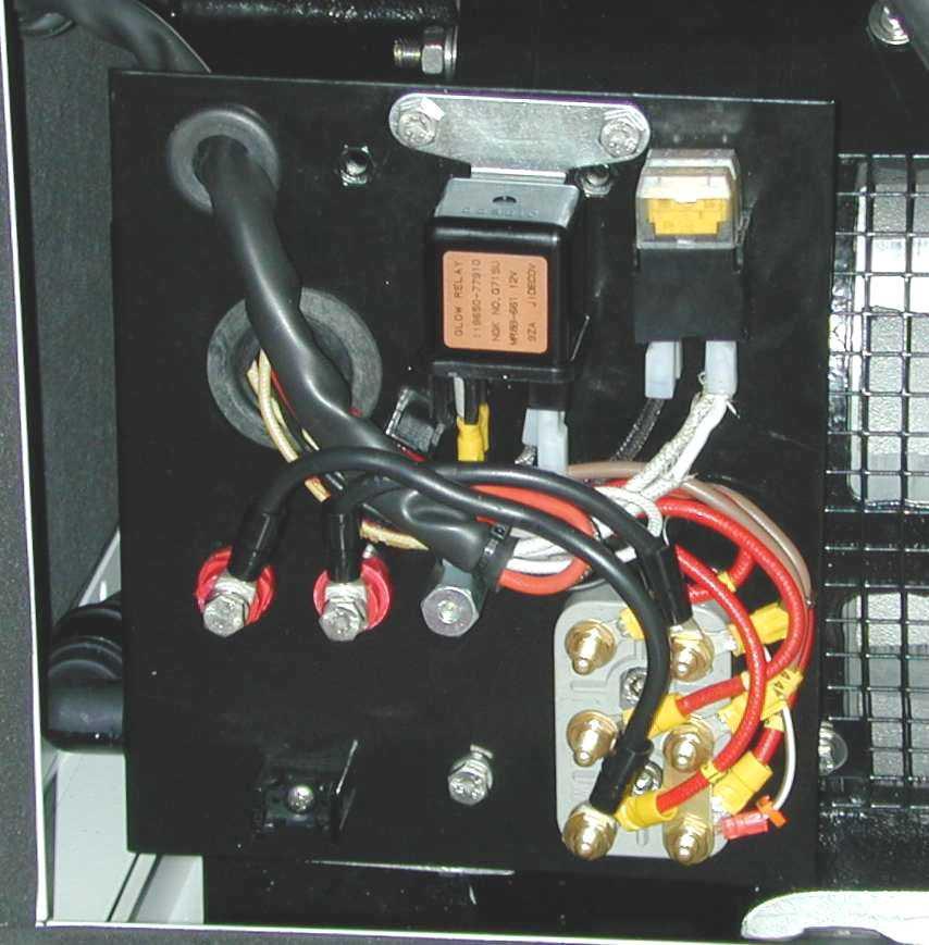
12 Anti-siphon valve must be inserted between the inlet of the sea water pump and exhaust manifold as indicated in Fig. 11 The drainage duct of the anti-siphon valve must run beneath the valve itself in order to prevent water accumulating in the duct, which should always remain empty to allow air to pass through when the unit is switched off. (see fig. 9) It is recommended that the drain hose from the antisiphon valve be fed into the bilge, as small amounts of water might be drained through it during normal operation. The cooling circuit is connected to the heat exchanger fitting as shown in Figure Drainage system The exhaust system of the generator must be separate from that of the main engine(s) The length of the tube from the highest point of the exhaust system to the muffler should not exceed 80". This is to prevent the water left in the drainage duct returning to the motor after filling the tank muffler, when the unit is turned off. 1 - Tank muffler This dampens the noise of the drainage and stops the water flowing back towards the motor. The muffler should be installed no less than 1 metre away from the generator and positioned at a height as per fig. 4/ Silencer This further reduces noise. It should be installed no more than 40" from the exhaust through-hull. 3 - Exhaust Through-Hull This must be installed in a position that is constantly above sea level in all the vessel s possible conditions of use. For further information, read the engine instruction manual, supplied by the engine manufacturer. 6 ELECTRICAL CONNECTIONS 6.1 Battery connection A battery of 12V, 70 Ah. is needed to start off the generator. It should be connected to the terminal of the generator (fig.12, ref.4) with cables of section 25 mm 2 up to distances of 16' 6" and with cables of section 35 mm 2 for longer distances, and following the sequence of operations described below: - First connect the positive pole (+) of the battery to the terminal marked with the symbol (+) on the generator. - Then connect the negative pole (-) of the battery to the terminal marked with the symbol (-) on the generator. - Wipe the connections with special mineral grease to protect against oxidation and corrosion. The generator includes an electronic device to automatically recharge the start-up battery, giving 15 A, at a voltage of 12 V, when fully charged. Install the battery in a wellventilated area, away from the generator and from any device which might produce heat or sparks. Periodically check the state of the connections of the terminals and the water level of the battery. If the cables need to be disconnected, follow the instructions for connection in reverse order. Do not invert the poles of the connecting cables since serious damage might be caused to the generator and the battery. Do not connect other loads to the battery. In order to reduce galvanic currents to a minimum, the (-) of the battery of the electric generator should not be connected to the (-) of the other batteries on board. 5 FUEL CIRCUIT The unit is fed by diesel fuel through the tubes marked fuel inlet (fig. 12 ref. 2 ) and fuel outlet (fig. 12 ref. 3). This latter is used for the return of the excess fuel. There is no need for filters in connections to the fuel tank, since the unit already contains a fuel filter; however it is advisable to fit a shut-off onto the fuel supply line downstream of the tank and a single-acting valve (check valve) to prevent the fuel system emptying for any reason. Use a valve with a 50 millibar opening. (Max head 31") The fuel lines should be in diesel fuel-resistant rubber, of inner diameter 8 mm (.31"). 6.2 Control panel connection There are two remote control panels available which can be connected to the generator for starting and stopping. Both models are supplied with a 65' electric connection cable with a connector fitted at the end. Fit the connector of the connection cable to the special coupling located at the lower part of the instrument panel casing inside the generator (Fig. 16 Ref. 1) and the opposite part to the remote control panel. 6.3 A.C. Connection This connection is made through the power terminal board located on the alternator of the generator (Fig. 14 Ref. 1). This terminal board is accessed by removing the panel as shown in Fig.13 Ref
13 This range of generators may be operated at both 120V - 60Hz and 240V -60Hz. Therefore, different connections (and thus uses) are possible according to the following configurations: 1 Parallel configuration; in this configuration there are two output : - 120V between the points 11 and 5 by connecting the alternator outputs and 2-5 according to the diagram in Fig. 15 Ref. 3. Use the insulators on the terminal board for the connection (Fig.14 Ref.2). 2 Serial connection; in this configuration there are two output : - 240V between the points 11 and 5 by connecting the alternator outputs 2-44 according to the diagram in Fig. 15 Ref. 4 Use the insulators on the terminal board for the connection (Fig.14 Ref.2) Generator - Main switching A switch should be placed in-line to switch the generator to shore power. The switch should be appropriate to the size of the loads: a general diagram is shown in fig LIFTING To lift the generator, use ONLY the provided lifting points. Hooking and/or lifting from any point other than the provided lifting point could damage the generator and cause a dangerous situation. With the series connection the power may be drawn simultaneously at a voltage of 120/240V 60Hz, as per the diagrams in Fig.15 Ref.5 and 6. If the series connection is used, to draw a voltage of 120V / 60Hz (Fig.15 Ref. 6), the current must not exceed 50% of the rated current. - Use the jumpers on the terminal board (Fig.15 Ref.1,2,3,4) to obtain both the parallel and the series connections. - Ensure that the sum of the loads to be fed does not exceed the rated output of the generator. - The generator is equipped with a circuit breaker which cuts the power in the event of an overload or short-circuit. Table of characteristics for single voltage Hz V kw A IS IS Table of characteristics for double voltage Hz V kw A IS IS
IS 11 IS 13.5 IS 15 IS 18.5 IS 21 IS 23 INSTALLATION MANUAL. 50 Hz. 60 Hz. 50 Hz. 60 Hz. 50 Hz. 60 Hz. COD i
 IS IS 3.5 IS 5 IS 8.5 IS IS 3 50 Hz 60 Hz 50 Hz 60 Hz 50 Hz 60 Hz INSTALLATION MANUAL COD. 4098i Fig. 3 4 Fig. Nomefile: miis5us.pm5 Data di aggiornamento: 06/0/98 Redatto: Service Paolucci - - Fig. 3
IS13.5 IS18.5 IS23 USAGE AND MAINTANENCE MANUAL
 IS1.5 IS18.5 IS USAGE AND MAINTANENCE MANUAL #19601 10 1 11 9 1 4 5 6 7 15 14 1 15871 8 1 4 1 5 7 6 8 9 10 11 1 1 4 6 5 4 7 8 9 1 TAB "A" 4 1 4 5 1 1 6 6 5 4 7 4 4 5 (/16") 10 mm (/8") 11 8 4 1 9 5 1 10
Installation instruction
 Installation instruction Intercalated generator CIC Reference : 60 300 143 09/2008 Complete 12V or 24V system Wet or gel battery 1 Installation instructions - Intercalated generator Table of contents Safety
PURE SINE WAVE DC TO AC POWER INVERTER
 PURE SINE WAVE DC TO AC POWER INVERTER 60S-12A / 60S-24A 60S-12E / 60S-24E 100S-12A / 100S-24A 100S-12E / 100S-24E 150S-12A / 150S-24A 150S-12E / 150S-24E Instruction manual SINE WAVE INVERTER Please read
Art. No. EC-315. Art. No. EC-330. Art. No. EC-340 SWITCH-MODE BATTTERY CHARGER CONTENTS IMPORTANT SAFETY PRECAUTIONS... 2
 SWITCH-MODE BATTTERY CHARGER CONTENTS IMPORTANT SAFETY PRECAUTIONS... 2 DESCRIPTION AND FEATURES... 3 CHARGING STAGES... 4 Art. No. EC-315 Art. No. EC-330 Art. No. EC-340 PROTECTIONS... 5 INSTALLATION...
3000W INVERTER MITM GENERATOR VENDOR: RATO MODEL: GEN-3000-IMM0 DATE: 5/25/15 DRAWN BY: JAY WESSELS DESCRIPTION:
 3000W INVERTER MITM GENERATOR VENDOR: RATO MODEL: GEN-3000-IMM0 DATE: 5/25/15 DRAWN BY: JAY WESSELS DATE: DESCRIPTION: BY: FIG.1 CYLINDER HEAD SUBASSEMBLY 1-01 BOLT - CYLINDER HEAD COVER 4 45-0315 90001-0612-01
Parts Catalog. Generator Set TGHAA (Spec A C) Printed in U.S.A. Replaces (Spec A) 1 97
 Printed in U.S.A. Replaces (Spec A) 1 97") Parts Catalog TGHAA Generator Set Printed in U.S.A. 9 00 (Spec A C) 9 Replaces 9 00 (Spec A) 97 To avoid errors or delay in filling your parts order, always give the MODEL, SPEC NO. and SERIAL NO. from
Parts Catalog TGHAA Generator Set Printed in U.S.A. 9 00 (Spec A C) 9 Replaces 9 00 (Spec A) 97 To avoid errors or delay in filling your parts order, always give the MODEL, SPEC NO. and SERIAL NO. from
1 GENERAL INFORMATION,
 CONTENTS 1 GENERAL INFORMATION, AND BOATING SAFETY HOW TO USE THIS MANUAL 1 2 BOATING SAFETY 1 3 SAFETY IN SERVICE 1-11 TOOLS AND EQUIPMENT 2-2 TOOLS 2-4 FASTENERS, MEASUREMENTS AND CONVERSIONS 2-12 ENGINE
1) Only gasoline exhaust systems shall be gas-tight to the hull interior
 Only gasoline exhaust systems shall be gas-tight to the hull interior") 1) Only gasoline exhaust systems shall be gas-tight to the hull interior 2) The primary purpose of an exhaust riser is to: a) direct laminar flow of exhaust gases overboard b) prevent water from flowing
1) Only gasoline exhaust systems shall be gas-tight to the hull interior 2) The primary purpose of an exhaust riser is to: a) direct laminar flow of exhaust gases overboard b) prevent water from flowing
English N Reference : Date : 12/2007 Version : A. This photograph does not necessarily represent the engine
 English N4.00 Reference : 970 34 343 Date : 2/2007 Version : A This photograph does not necessarily represent the engine N4.00 - Owner s manual Technical characteristics Engine specifications Cycle 4 strokes,
High Pressure Abrasive Blast Cabinet 42000
 Please read and save these instructions. Read through this owner s manual carefully before using product. Protect yourself and others by observing all safety information, warnings, and cautions. Failure
Installation Instructions for Load Management Kit A051C329
 Instruction Sheet 12-2014 Installation Instructions for Load Management Kit A051C329 1 Introduction The information contained within is based on information available at the time of going to print. In
OPERATION INSTRUCTIONS
 www.r-techwelding.co.uk Email: sales@r-techwelding.co.uk Tel: 01452 733933 Fax: 01452 733939 ProArc 175 INVERTER ARC WELDER OPERATION INSTRUCTIONS Version 2017-10 2 3 Thank you for selecting the R-Tech
Fully Automatic Bilge Pump INSTRUCTION MANUAL
 Fully Automatic Bilge Pump INSTRUCTION MANUAL Purpose of this manual The purpose of this manual is to provide necessary information for product installation, operation and maintenance. CAUTION: Read this
1/2" AIR DRIVEN DIAPHRAGM PUMP
 1/2" DRIVEN DIAPHRAGM PUMP OPERATION AND SERVICE GUIDE O-1225D NOV. 2008 Page 1 of 6 Refer to Bulletin P-605, Parts List P-9151 DRIVEN, DOUBLE DIAPHRAGM PUMP MANUAL Congratulations on purchasing one of
MMA 160S ARC/MMA WELDER OPERATION INSTRUCTIONS
 www.r-techwelding.co.uk MMA 160S ARC/MMA WELDER OPERATION INSTRUCTIONS 2 Thank you for selecting the R-Tech MMA160S Inverter Arc Welder. The MMA160S has many benefits over traditional Arc welders, including
BSS Examination Record Form for Privately Owned and Managed Vessels
 BSS Examination Record Form for Privately Owned and Managed Vessels [Edition 1.04 April 2013] Current boat name Former name Reg. number or index Length (m) Berths Hull material Hull colour Superstructure
OPERATION MANUAL, POWER MODULE-CHARGER SYSTEM. Man Occup. Machine Occup. Cycle Time Setup Time Batch Qty. Equipment Manufacturer Qty
 Rev Description Date ECO# Document Number: OPERATION MANUAL 3/24/08 00263 Form Instructions Title Operation Description Standards OPERATION MANUAL, POWER MODULE-CHARGER SYSTEM Power Module-Charger System
VERTICAL MULTI-STAGES CENTRIFUGAL PUMPS
 Installation and Operating Instructions VERTICAL MULTI-STAGES CENTRIFUGAL PUMPS Models 1, 3, 5, 10, 15, 20, 32, 45, 64, 90, 120, 150 1. Model numbering and nameplate format 1.1 Model numbering Example:
Installation Instructions
 010A00 011A00 014A00 SMALL ROOFTOP UNITS TWO POSITION OUTDOOR AIR DAMPER 2to15TONS (50/60 Hz) Installation Instructions TABLE OF CONTENTS PACKAGE CONTENTS... 1 PACKAGE USAGE... 1 SAFETY CONSIDERATIONS...
Exhaust Alert Installation & Operating Instructions THE SCIENCE OF SILENCE. Exhaust Alert Operating & Fitting Instructions 1
 Exhaust Alert Installation & Operating Instructions THE SCIENCE OF SILENCE Exhaust Alert Operating & Fitting Instructions 1 Contents Exhaust Alert Fitting Instructions Section Page 1 Introduction 2 1.1
This generator set has been designed to meet ISO 8528 regulation. Enclosed product is tested according to EU noise legislation 2000/14/EC
 This generator set has been designed to meet ISO 8528 regulation. This generator set is available with CE certification. Enclosed product is tested according to EU noise legislation 2000/14/EC 3 Phase
Service Manual Outline
 Service Manual Outline Section 1 - Important Information A - General Information B - Maintenance Section 2 - Removal, Installation and Adjustment A - All Models Section 3 - Sterndrive Unit A - Drive Shaft
36 HYPER MAX DIRECT DRIVE GALVANIZED BOX FAN
 Assembly & Installation Manual Read carefully the information provided. Retain manual for future reference. 36 HYPER MAX DIRECT DRIVE GALVANIZED BOX FAN IS10063.DOC Step 1 Unpack and become familiar with
VERTICAL MULTI-STAGE CENTRIFUGAL PUMPS
 Installation and Operating Instructions VERTICAL MULTI-STAGE CENTRIFUGAL PUMPS Models 1, 3, 5, 10, 15, 20, 32, 45, 64, 90 1. Model numbering and nameplate format 1.1 Model numbering Example: SBI / SBN
HOT WASHER MODEL NO: KING 125 OPERATION & MAINTENANCE INSTRUCTIONS PART NO: LS1009
 HOT WASHER MODEL NO: KING 125 PART NO: 7320170 OPERATION & MAINTENANCE INSTRUCTIONS LS1009 INTRODUCTION Thank you for purchasing this Hot Washer. This machine is a portable, high pressure power washer,
Ten Deadly Conditions to Check for in Your Boat's Electrical System - Part 2
 Ten Deadly Conditions to Check for in Your Boat's Electrical System - Part 2 In the September newsletter, 1 through 5 of the ten deadly conditions were presented (link to previous article). Deadly conditions
1000 Watt Power Inverter INSTRUCTION MANUAL HT87112-AUOXY
 1000 Watt Power Inverter INSTRUCTION MANUAL HT87112-AUOXY CONTENTS Warranty 2 Introduction 3 Environmental protection 3 Specifications 3 General safety warnings and instructions 4 Important safety instructions
MULTIVOLTAGE PORTABLE BATTERY CHARGER MVM
 _ M MULTIVOLTAGE PORTABLE BATTERY CHARGER MVM User's MANUAL Code: MVM Version: 01-BF Date: OCT 2005 Page 1/10 _ 1. INTRODUCTION Before starting to use your Energic plus MVM battery charger, please take
(Bio)Diesel Battery Chargers... DC Amps at 12/24/48 Volts
Diesel Battery Chargers... DC Amps at 12/24/48 Volts") Ample Power... the name says it all! 1 (Bio)Diesel Battery Chargers... DC Amps at 12//48 Volts V, 175 Amps... now available in flat belt. Flat Plate Design.... Never out of alignment.... Automatic belt
Ample Power... the name says it all! 1 (Bio)Diesel Battery Chargers... DC Amps at 12//48 Volts V, 175 Amps... now available in flat belt. Flat Plate Design.... Never out of alignment.... Automatic belt
Instruction Manual. Johnson Ultra Ballast Pump. Johnson Pumps
 Johnson Pumps Instruction Manual Johnson Ultra Ballast Pump SPX Flow Technology Nastagatan 19, P.O. Box 1436 SE-701 14 Örebro, Sweden E-mail: johnson-pump.marine@spx.com Copyright 2009 SPX Corporation
This generator set has been designed to meet ISO 8528 regulation. This generator set is manufactured in facilities certified to ISO 9001.
 This generator set has been designed to meet ISO 88 regulation. This generator set is manufactured in facilities certified to ISO 900. This generator set is available with CE certification. Enclosed product
part three electrical installations
 part three electrical installations Cleat Hitch Faulty electrics, or poorly installed electrical systems, can be a real hazard and could place you and others at risk. This part of the Standards aims to
PHASE CONVERTERS OPERATING & MAINTENANCE INSTRUCTIONS. MODEL NO: PC40 and PC60. PART Nos:
 PHASE CONVERTERS MODEL NO: PC40 and PC60 MODEL PART No: NO: 6012805 PC20 and PC40 6012810 PC60 PART Nos: 6012800 6012805 6012810 OPERATING & MAINTENANCE INSTRUCTIONS 0107 Specifications PC20 PC40 PC60
English N4.85. Reference : Date : 12/2007 Version : A. This photograph does not necessarily represent the engine
 English N4.85 : 970 34 956 Date : 2/2007 Version : A This photograph does not necessarily represent the engine N4.85 - Owner s manual Technical characteristics Engine specifications Cycle 4 strokes, Diesel
Installation 6EKOD 9-11EKOZD 5EFKOD 7-9EFKOZD. Marine Generator Sets. Models: TP /11
 Installation Marine Generator Sets Models: 6EKOD 9-11EKOZD 5EFKOD 7-9EFKOZD TP-6773 10/11 2 TP-6773 10/11 Table of Contents Safety Precautions and Instructions... 5 Section 1 Introduction... 9 Section
Monicon Instruments Co., Ltd. CHR-1285/2485 CHR-1285/2485 BATTERY CHARGER
 CHR-1285/2485 BATTERY CHARGER TEL:886-4-2238-0698 FAX:886-4-2238-0891 Web Site:http://www.monicon.com.tw E-mail:sales@monicon.com.tw Copyright 2007 Monicon Instruments Co., Ltd. All right reserved. Contents
Matrix APAX. 380V-415V 50Hz TECHNICAL REFERENCE MANUAL
 Matrix APAX 380V-415V 50Hz TECHNICAL REFERENCE MANUAL WARNING High Voltage! Only a qualified electrician can carry out the electrical installation of this filter. Quick Reference ❶ Performance Data Pages
WHISPERPOWER GENERATOR SETS
 ADDITIONAL MANUAL FOR KEEL COOLING APPLICATIONS WHISPERPOWER GENERATOR SETS Art.nr. 40200251 WHISPER POWER BV Kelvinlaan 82 9207 JB Drachten Netherlands Tel.: +31-512-571550 Fax.: +31-512-571599 www.whisperpower.eu
Hydraulic Immediate Need Power Pack
 Safety, Operation, and Maintenance Manual WARNING Improper use of this tool can result in serious bodily injury This manual contains important information about product function and safety. Please read
Pure sine wave charger inverter Product Manual
 Pure sine wave charger inverter Product Manual The inverter installer must be professional, for the high pressure in the inverter, unprofessional person please do not open it. The inverter should be installed
Model: PI-140 Power Inverter Converts 12V DC battery power to 120V AC household power
 OWNER S MANUAL Model: PI-140 Power Inverter Converts 12V DC battery power to 120V AC household power READ THE ENTIRE MANUAL BEFORE USING THIS PRODUCT. FAILURE TO DO SO COULD RESULT IN SERIOUS INJURY OR
REFERENCE MANUAL FORM: MX-TRM-E REL REV MTE
 Matrix APAX 380V-415V 50Hz TECHNICAL REFERENCE MANUAL FORM: MX-TRM-E REL. September 2014 REV. 002 2014 MTE Corporation WARNING High Voltage! Only a qualified electrician can carry out the electrical installation
Parts Catalog MDKBD MDKBE MDKBF
 Parts Catalog MDKBD MDKBE MDKBF Printed U.S.A. /0 00C To avoid errors or delay in filling your parts order, always give the MODEL, SPEC NO. and SERIAL NO. from the Onan nameplate. For handy reference,
Medium and high pressure pumps
 Screw pumps Medium and high pressure pumps Installation and Start-up Instruction This instruction is valid for all standard high pressure pumps: E4, D4 and D6 Contents Page Pump identification 2 Installation
original operating manual Operating manual Translation of the Item-No.: ,
 Translation of the original operating manual Operating manual Item-No.: 015 431 551, 015 431 581 Important! Copyright The operating manual is always to be read before commissioning the equipment. No warranty
2000W INVERTER MITM OUTDOOR GENERATOR VENDOR: RATO MODEL: GEN DM0 DATE: 4/27/15 DRAWN BY: ADAM COATES
 2000W INVERTER MITM OUTDOOR GENERATOR VENDOR: RATO MODEL: GEN-2000-0DM0 DATE: 4/27/15 DRAWN BY: ADAM COATES DATE: DESCRIPTION: BY: 9/3/2015 CHANGE DESCRIPTION ON 80-0181 TO REMOVE GFCI ALC FIG.1 ENGINE
Design specifications
 Design specifications Design To relevant standards: IEC, VDE, DIN, ISO, EN With squirrel-cage or slipring rotor Degree of protection IP 55 / IP 65 Cooling method IC511, suitable for both indoor and outdoor
D Instructions/Parts. Siphon Feed Detail Spray Gun D
 Instructions/Parts D-5-55 Siphon Feed Detail Spray Gun FOR PRODUCT INFORMATION CALL: 1-800-742-7731 309991D Important Safety Instructions Read all warnings and instructions in this manual. Save these instructions.
Power InverterTM Watt. Continuous. User's Manual. WAGAN Corp. Limited Warranty Registration Form. Item no
 WAGAN Corp. Limited Warranty Registration Form All WAGAN Corporation products are warranted to the original purchaser of this product. Warranty Duration: This product is warranted to the original purchaser
PRO PRO20-115RD 115-Volt AC. PRO Volt AC OWNER'S MANUAL SAVE THESE INSTRUCTIONS
 OWNER'S MANUAL SAVE THESE INSTRUCTIONS PRO20-115 PRO20-115RD 115-Volt AC PRO20-115AD Automatic Diesel Nozzle PRO20-115MD Manual Diesel Nozzle PRO20-115PO Pump Only PRO20-115RD For Remote Dispensing Systems
This generator set has been designed to meet ISO 8528 regulation. This generator set is manufactured in facilities certified to ISO 9001.
 This generator set has been designed to meet ISO 88 regulation. This generator set is manufactured in facilities certified to ISO 900. This generator set is available with CE certification. Enclosed product
Installation manual ENGLISH GHX GLX. Generator Sets kva. Copyright 2016 Vetus b.v. Schiedam Holland
 Installation manual ENGLISH GHX GLX Generator Sets 6-24 kva Copyright 2016 Vetus b.v. Schiedam Holland 380602.01 Contents 1 Safety Information 3 1.1 Warning indications 3 1.2 Symbols 3 1.3 Safety rules
TABLE OF CONTENTS. 300 W Mobile Power Outlet SAVE THESE INSTRUCTIONS!
 300 W Mobile Power Outlet 011-1870-6 TECHNICAL SPECIFICATIONS... 3 Safety Information... 4 KEY PARTS diagram... 7 INTENDED USE... 9 Options for connecting devices to the power inverter... 9 Operation...
INSTALLATION INSTRUCTIONS
 www.burcam.com 2190 Dagenais Blvd.West TEL: 514.337.4415 LAVAL (QUEBEC) FAX: 514.337.4029 CANADA H7L 5X9 info@burcam.com Your pump has been carefully packaged at the factory to prevent damage during shipping.
SUBMERSIBLE WATER PUMP OPERATING & MAINTENANCE INSTRUCTIONS. Model Nos. CSE400A. Part No iss 2
 SUBMERSIBLE WATER PUMP Model Nos. CSE400A Part No. 7231100 0917 iss 2 OPERATING & MAINTENANCE INSTRUCTIONS Thank you for purchasing this Clarke Submersible Pump. This highly efficient pump is designed
M-3025CB-AV Fuel Pump
 SAVE THESE INSTRUCTIONS M-3025CB-AV Fuel Pump Owner s Manual TABLE OF CONTENTS General Information... 2 Safety Instructions... 2 Installation... 3 Operation... 4 Maintenance... 4 Repair... 5 Troubleshooting...
Vertical Chemical Pumps
 Vertical Chemical Pumps JKD/JKT/JKH/JKP/JKV Series Instruction Manual JIEKAI INDUSTRIAL EQUIPMENT CO., LTD. 0 1. Introduction Table of Contents Model Definition... 2 Specification And Suitable Applications...
AQUIS Foam System. Installation, Operation, and Maintenance Instructions AQUIS 1.5, AQUIS 3.0, and AQUIS 6.0
 Form Number: F-1031 Issue Date: Aug 1, 2017 Section: 2447 Revision Date: Sept 7, 2018 AQUIS Foam System Installation, Operation, and Maintenance Instructions AQUIS 1.5, AQUIS 3.0, and AQUIS 6.0 Waterous
This generator set has been designed to meet ISO 8528 regulation. This generator set is manufactured in facilities certified to ISO 9001.
 This generator set has been designed to meet ISO 88 regulation. This generator set is manufactured in facilities certified to ISO 900. This generator set is available with CE certification. Enclosed product
 IU0U automatic charger Read these instructions carefully before the installation and commissioning and keep them in a safe place. Pass it on to the buyer in case of the further sale of the system. Contents
This generator set has been designed to meet ISO 8528 regulation. This generator set is manufactured in facilities certified to ISO 9001.
 This generator set has been designed to meet ISO 8528 regulation. This generator set is manufactured in facilities certified to ISO 9001. This generator set is available with CE certification. Enclosed
PARTS MANUAL. RGV12000/12100 Generator. Model. PUB-GP1420 Rev. 12/01
 PARTS MANUAL Model RGV12000/12100 Generator PUB-GP1420 Rev. 12/01 Copyright 2001 Robin America, Inc. GROUP INDEX Group Name Page GENERATOR... 4 PIPE FRAME... 6 CONTROL BOX... 8 2-WHEEL ASSY.... 12 4-WHEEL
Brake System H TX, H2.0TXS [B475]; H TX [B466] Safety Precautions Maintenance and Repair
![Brake System H TX, H2.0TXS [B475]; H TX [B466] Safety Precautions Maintenance and Repair](/thumbs/86/93834005.jpg "Brake System H TX, H2.0TXS [B475]; H TX [B466] Safety Precautions Maintenance and Repair") HMM180001 Brake System H1.5-1.8TX, H2.0TXS [B475]; H2.5-3.5TX [B466] Safety Precautions Maintenance and Repair When lifting parts or assemblies, make sure all slings, chains, or cables are correctly fastened,
HMM180001 Brake System H1.5-1.8TX, H2.0TXS [B475]; H2.5-3.5TX [B466] Safety Precautions Maintenance and Repair When lifting parts or assemblies, make sure all slings, chains, or cables are correctly fastened,
Voltage kva kw kva kw Amp 400/ ,00 388,00 425,00 340,00 613,00 OTHER ACCESSORIES
 This generator set has been designed to meet ISO 8528 regulation. This generator set is manufactured in facilities certified to ISO 9001. This generator set is available with CE certification. Enclosed
Installation, Operating, Maintenance and Safety Instructions for CW332 Pressurised water system for boats 24 volt d.c.
 24V DC-CW332 DOC531/11 Installation, Operating, Maintenance and Safety Instructions for CW332 Pressurised water system for boats 24 volt d.c. To obtain the best performance from your Pressurised water
EJECTORS GENERAL OPERATION & MAINTENANCE MANUAL
 EJECTORS GENERAL OPERATION & MAINTENANCE MANUAL The information contained in this manual was current at the time of printing. The most current versions of all Hydro Instruments manuals can be found on
MANUAL D250S DUAL. Solar panel + Vehicle ground/solar panel
 MANUAL CONGRATULATIONS on the purchase of your new CTEK professional battery management unit. This unit is part of a range of professional battery chargers from CTEK SWEDEN AB. It represents the latest
QUOTATION BLADE 7 LX. Product code GEAL6S2BAA
 1 of 10 Mattei rotary vane compressors are the result of 90 years of investments in research and development to improve performance and lessen the impact on the environment. Designed for industrial continuous
SUBMERSIBLE WATER PUMPS
 SUBMERSIBLE WATER PUMPS Model Nos. CS85S - CS85SA CS120S - CS120SA CS185S - CS185SA CS240S - CS240SA CS305S - CS305SA OPERATING & MAINTENANCE INSTRUCTIONS 1000 CONTENTS Warranty conditions... 3 Safety
NECO Pumping Systems
 INSTALLATION OPERATION & MAINTENANCE INSTRUCTIONS For Your NECO Pumping Systems PACKAGED CIRCULATING SYSTEM THIS COMPLETELY ASSEMBLED, TESTED, PACKAGED CIRCULATING SYSTEM IS OF THE HIGHEST QUALITY AND
DR Series Reactive Discharge Dampeners For Drilling
 DR Series Reactive Discharge Dampeners For Drilling Instruction, Operating & Maintenance Manual Manufacturer of Pulsation Control Products 1.833.PPC.PROD 3309 Essex Dr. Suite 200, Richardson, Texas 75082
Parts Catalog MDKBP MDKBR MDKBS
 Parts Catalog MDKBP MDKBR MDKBS Printed U.S.A. 0 0 To avoid errors or delay in filling your parts order, always give the MODEL, SPEC NO. and SERIAL NO. from the Onan nameplate. For handy reference, insert
MODEL 6010A 6 12 VOLT BATTERY CHARGER ASSOCIATE
 MODEL 600A 6 VOLT BATTERY CHARGER ASSOCIATE IMPORTANT SAFETY INSTRUCTIONS. SAVE THESE INSTRUCTIONS. This manual contains important safety and operating instructions for the battery charger you have purchased.
Installation 4EOZ/3.5EFOZ 6EOD/4.5EFOD 8-32EOZD/6.5-27EFOZD. Marine Generator Sets. Models: TP /08c
 Installation Marine Generator Sets Models: 4EOZ/3.5EFOZ 6EOD/4.5EFOD 8-32EOZD/6.5-27EFOZD TP-6253 1/08c 2 TP-6253 1/08 Table of Contents Safety Precautions and Instructions... 5 Section 1 Introduction...
DISCHARGER-ANALYZER BDX USER'S MANUAL
 BATTERY DISCHARGER-ANALYZER BDX USER'S MANUAL OWM-BDX-261006 Page 1/10 1. INTRODUCTION Before starting to use your BDX battery discharger/analyzer, please take the time to read these instructions carefully.
Oil-free piston compressors KK and piston vacuum pumps KV
 Oil-free piston compressors KK and piston vacuum pumps KV Installation and Operating Instructions 0678106030L02 1707V003 Contents Important information 1 About this document 2 1.1 Warnings and symbols
INSTALLATION, OPERATION AND MAINTENANCE INSTRUCTIONS
 INSTALLATION, OPERATION AND MAINTENANCE INSTRUCTIONS Contents Section 1. General Observations... 2 2. Operation... 4 3. Control During Operation... 5 4. Trouble Shooting... 6 5. Maintenance... 7 Please
Installation manual. Exhaust system. Marine engines DI09, DI13, DI16. 02:04 Issue 9.0 en-gb. Scania CV AB 2017, Sweden
 Installation manual Exhaust system Marine engines DI09, DI13, DI16 333 380 02:04 Issue 9.0 en-gb Changes from the previous issue...3 Important data... 30 Sound reduction...3 Exhaust noise... 3 Exhaust
Centrifugal Pumps (Part Nos. PS2SS PS73SS) PS2SS
 PS2SS") Centrifugal Pumps (Part Nos. PS2SS PS73SS) PS2SS Part No. Serial Number Date Purchased Table of Contents Page Safety Messages...2 Pump Curves...2 Pump End Assembly...3 Disassembly...3 Installation...4
Centrifugal Pumps (Part Nos. PS2SS PS73SS) PS2SS Part No. Serial Number Date Purchased Table of Contents Page Safety Messages...2 Pump Curves...2 Pump End Assembly...3 Disassembly...3 Installation...4
IMPORTANT INFORMATION
 Table of Contents IMPORTANT INFORMATION Section 1B - Maintenance MAINTENANCE 1 B Specifications........................... 1B-1 Special Tools........................... 1B-2 Mercury/Quicksilver Lubricants
Please call us at Mon-Fri 8am-5pm if you need any additional assistance.
 TM Upgraded 6.0L EGR Cooler R Thank you for purchasing a Sinister Diesel Upgraded EGR Cooler. This EGR cooler is designed to endure years of heavy use.these installation instructions have been written
1 2 3a 3b THREADING CARD 9 10 ABC Office
 1 2 3a 3b 4 5 6 7 8 9 10 THREADING CARD Important Safety instructions YOUR SAFETY AS WELL AS THE SAFETY OF OTHERS IS IMPORTANT TO GBC. IN THIS INSTRUCTION MANUAL AND ON THE PRODUCT ARE IMPORTANT SAFETY
If there is additional labor or other costs above the 4 hrs labor you must call VMAC for approved coverage
 Installation Manual for the A500027 RAPTAIR MF Dual Air Filter Retrofit Kit Author: Brian Collings Date: 15/07/2014 1900997 - Manual, Installation (A500027) Systems or Parts Affected: D600005BETA01-D600005BETA59
Monocellular centrifugal electro-pumps
 Réf. 2100 - O33 / a - 5.95 This manual must be given to the end user LS Monocellular centrifugal electro-pumps Installation and maintenance 1 - GENERAL The LS range of monobloc electro-pump units should
Installation. 5EKD/4EFKD -Low CO 7.5EKD/6EFKD -Low CO 10EKD/8EFKD -Low CO. Marine Generator Sets. Models: Controller: Advanced Digital Control II
 Installation Marine Generator Sets Models: 5EKD/4EFKD -Low CO 7.5EKD/6EFKD -Low CO 10EKD/8EFKD -Low CO Controller: Advanced Digital Control II TP-6592 3/13a 2 TP-6592 3/13 Table of Contents Safety Precautions
1100W PORTABLE GENERATOR
 1100W PORTABLE GENERATOR MODEL NO: G1200 PART NO: 8010110 OPERATION & MAINTENANCE INSTRUCTIONS LS0312 INTRODUCTION Thank you for purchasing this CLARKE 1100W Portable Generator. Before attempting to use
L-SERIES PUMPS. Operating Manual. Includes Pumps: L-305 L PONDS
 L-SERIES PUMPS Operating Manual Includes Pumps: L-305 L-310 1-877-80-PONDS www.atlanticwatergardens.com Introduction Thank you for selecting the TidalWave L-305/L-310 series pumps. Before using this pump
Parts Catalog MDKAU. Printed U.S.A C
 Parts Catalog Printed U.S.A. 00 0C To avoid errors or delay in filling your parts order, always give the MODEL, SPEC NO. and SERIAL NO. from the Onan nameplate. For handy reference, insert your nameplate
General safety and installation information.
 Read these instructions before connecting and using your PowerBright Pure Sine Power Inverters. Failure in observing this warning may result in injury to persons and damage to equipment. General safety
Installation manual. Modbus Interface DIII EKMBDXA7V1. Installation manual Modbus Interface DIII. English
 Modbus Interface DIII EKMBDXA7V1 Modbus Interface DIII English 379 mm 0 C 100 mm 50 mm 50 mm 40 mm 87 mm 300 mm IP X0 50 mm 60 C 365 mm 124 mm Max. 100 mm Min. 1 2 3 1 www.daikineurope.com/support-and-manuals/product-information/
Genset. Parts Catalog HDKAG
 Genset Parts Catalog HDKAG To avoid errors or delay in filling your parts order, always give the MODEL, SPEC NO. and SERIAL NO. from the Onan nameplate. For handy reference, insert your nameplate information
Toothed belt axis ELGC-TB-KF. Operating instruction [ ]
![Toothed belt axis ELGC-TB-KF. Operating instruction [ ]](/thumbs/83/87984161.jpg "Toothed belt axis ELGC-TB-KF. Operating instruction [ ]") Toothed belt axis ELGC-TB-KF en Operating instruction 8068220 2017-02 [8068222] Original instructions Identification of hazards and instructions on how to prevent them: Danger Immediate dangers which can
Toothed belt axis ELGC-TB-KF en Operating instruction 8068220 2017-02 [8068222] Original instructions Identification of hazards and instructions on how to prevent them: Danger Immediate dangers which can
abc CPD7948/075 Rotors, rotor shafts and rotor casings are coated with an anti-corrosive and anti wear coating to prolong element life and efficiency.
 CPD7948/075 Specification Oil-Free, Air Cooled, Rotary Screw Compressors - Dryclon Range Models D75, D90, D110, D132, D150 (50Hz) D55, D75, D90, D110, D150 (60Hz) COMPRESSOR PACKAGE An enclosed two stage
Drilling Series SC Series Cellular Suction Stabilizers Instruction, Operating & Maintenance Manual
 Drilling Series SC Series Cellular Suction Stabilizers Instruction, Operating & Maintenance Manual Manufacturer of Pulsation Control Products 3309 Essex Dr. Suite 200, Richardson, Texas 75082 Phone: 972.699.8600
Usage Instructions of Solar Control for 3Way-Ball Valve
 Table of Contents: Page: 2 Safety Instructions 3 Intended Use / General / Warranty / Installation: 4 Schematic Diagram: Mounting the sensor 5 Start-UP 6 Note: 7 Electrical connections: Technical Specifications
Operation of the FFBH is enabled and disabled by the Automatic Temperature Control Module (ATCM).
.") Page 1 of 8 Published : Apr 22, 2004 Auxiliary Heater COMPONENT LOCATIONS Item Part Number Description 1 - Fuel line connection with fuel tank 2 - Auxiliary fuel pump 3 - Fuel fired booster heater GENERAL
Page 1 of 8 Published : Apr 22, 2004 Auxiliary Heater COMPONENT LOCATIONS Item Part Number Description 1 - Fuel line connection with fuel tank 2 - Auxiliary fuel pump 3 - Fuel fired booster heater GENERAL
Installation & Technical Guide. Domestic & Commercial.
 Installation & Technical Guide Domestic & Commercial www.challisbooster.com www.challisboosterplus.com Installation and Technical Guide Domestic and Commercial Challis Water Controls Europower House, Lower
Operating Instruction Manual of Energy Management System EBL 208, Art.-No Seite 1 / 7
 EBL 208, Art.-No 911.430 Seite 1 / 7 Contents 1. Description 2. Safety Information 3. Operating Instructions 4. Transport, Storage, Installation 5. Electrical Installation 6. Power-Up, Shut-Down, Maintenance
Daikin Steam Coils. Installation and Maintenance Manual IM 901. Types HI-F5, HI-F8, & E-F5. Group: Applied Air. Part Number: IM 901
 Installation and Maintenance Manual IM 901 Daikin Steam Coils Group: Applied Air Part Number: IM 901 Date: February 2008 Types HI-F5, HI-F8, & E-F5 2008 Daikin Applied Contents Introduction... 3 General