Bill of Materials: Spinning top brushless DC motor PART NO
|
|
|
- Betty Hodge
- 5 years ago
- Views:
Transcription
1 Spinning top brushless DC motor PART NO The heart of this kit consists of a bifilar wound coil driven with two NPN transistors. While the circuit is easy, the coil will be tedious to wind since each wire is about 200 to 250 feet long. Neatness will help keep the size of the coil down. All parts are available through Jameco except the mirror, spindle and magnet. The options for the base will also have to be considered. Various materials can be used including wood and plexiglass. It is important to keep the battery away from the magnet at least 5 inches. The base can also serve as the bobbin for the coil keeping the parts count low. The addition of a single small rectifier diode will allow for connecting an optional small solar panel to the unit. Installing a rechargeable battery will keep the top going indefinitely. Time Required: 4 to 6 hours. depending on experience Experience Level: Intermediate Required tools and parts: Soldering iron. Wire cutters. Wire strippers. Screw drivers. Sand paper. Bill of Materials: Qty Jameco SKU Component Name N3904 NPN transistor Any small signal or general NPN transistor will work as long as the leads match the pattern on the PCB K resistor Î resistor Current limiting resistor for LED's Red LED Any color will do, the brighter the better. These LED's make the plexiglas base glow. The intensity will vary with the movement of the magnet ga. magnet wire This wire will need to be cut in half for the coil. Each half will need to be on its own bobbin for easier winding Battery holder A pc mount battery holder would also work and make assembly a little easier. 1 Mirror These mirrors are available in most department stores and range in price from $3 to $15. I recommend X10 magnification. X5 will also work however the top will be less energetic but also quieter. 1 Double pointed #3 knitting needles A package of four needles will make spindles for 8 tops. The end of the needle is cut to a length of 1 3/4 inches. 1 1" diametrically magnetized ring magnet. This magnet will fit nicely on the #3 knitting needle. A couple gentle taps will fit the magnet to the the needle. The needle is similar to a morris tapered shaft. 1 Base 3 1/2" X 5" Base (1/4" plexiglass)

2 This part has to be fabricated at a shop that works with plexiglas. 1 Miscellaneous Screws / Hardware The Jameco battery holder has one screw hole in the center a 1/2" 4-40 flathead screw will hold it to the base. 5/8" rubber feet can be added for support and to keep the screw from scratching wooden surfaces Solder-less Breadboard Using this part eliminates the need for soldering and allows easy component swapping for experimenting purposes. Step 1 - Inventory Parts. Open the kit and compare the parts list to the actual parts in the kit. You may receive extra components for some items. Step 2 - Familiarize yourself with the base plate There are six holes in the base plate (see photo). Two holes to attach the circuit board (this board is the solderable version for permanent construction Jameco Part# ). The solder less board provided in the kit will be secured with a rubber band. One hole to attach the battery holder. Two holes to guide the wire from the coil. One hole for the LED's. Step 3 - Attach the cable ties Tape two cable ties (one to the top of the base and one to the bottom of the base) as shown in the photo. The sides with the locking ridges should be facing out away from the base. Step 4 - Start the coil Hold the base with the top side facing away from you (the base is reversible so either side can be the top). Feed both wires through either one of the guide holes (your choice) leaving the other hole empty. Feed enough wire through to reach the end of the base where the battery holder will be and tape them down (see photo).
 notch, this will give needed slack later. Keep all the turns in the notches.")

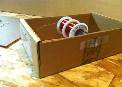
3 Step 5 - Wind the coil NOTE: It is highly recommended that you make a simple spool holder out of a cardboard box and piece of stiff wire to complete this step (see reference 1 photo). Begin winding the wires toward the opposite (farthest) notch, this will give needed slack later. Keep all the turns in the notches. Wind the layers as neat as possible however perfection is not necessary. It will take about 1 to 2 hours to wind the coil by hand so be patient. It is best to wind the coil by flipping the base over and over while holding the wire stationary. If you wrap the wire around the base while holding the base stationary, it will twist up on itself eventually causing kinks and difficulty winding. When you reach the end of the wires or fill the notches (which ever comes first) feed the ends through the remaining guide hole and tape them to the base as you did at the beginning (see photo). Make sure they are long enough to reach the end of the base where the battery holder will be. Cinch the cable ties around the wires to help hold them in place. When we reach the step where the wires are attached to the circuit board, two of the wires will cross sides. Step 6 - The winding process You will notice that some of the windings will appear loose on the front and back sides of the coil. There is no cause for concern as the cable ties will pull the windings together.


4 Step 7 - Complete the coil The coil is completed when either you run out of wire or the notches are full. Do not exceed the capacity of the notches. Cut the wires long enough to reach the end of the base where the battery holder will go. Feed them through the open guide hole and tape them to the base. Step 8 - Sand the wires Now that the coil is wound it is a good idea to remove the insulation from the wires. You will need a small piece of sand paper 150 grit or finer. Pinch a wire between the thumb and index finger. Fold the sand paper over the wire with the other hand and pull. Repeat this about ten times until the wire is shiny. Make sure to move the sand paper around the wire a little each time to get all the enamel. Repeat this for the other three wires.


5 Step 9 - Center tap Position the base with the coil away from you. Set the multimeter to low ohms scale. Attach one lead of the multimeter one of the wires on the left side of the coil and the other lead to one of the wires on the right side of the coil. If there is no reading move the lead to the other wire. You should get a reading of about 25 ohms. Leave the meter connected to those wires and pull the other two wires that are not connected to the meter back through the guide holes. Route the wire that was on the right through the left guide hole and the wire that was on the left through the right guide hole. Disconnect the meter and twist the two wires on the right side of the base together, they will be the center tap. Attach one probe of the meter to the center tap and the other to one of the two wires on the left. The reading should be about 25 ohms. Now test the other wire on the left. It also should read about 25 ohms. Step 10 - Mount The Breadboard This is a good time to get these components ready. There should be: 2 transistors. 4 resistors: two 2.2Kohm and two 150ohm. 2 LED's. 1 Breadboard.
. There should be five empty holes between the two wires.")
. The collector will be the lead on the left in this configuration.")
6 Step 11 - Breadboard assembly 1 Place two wires in the position shown. Note: the board in the picture is longer than the one in the actual kit. Once the board is centered the two wires should line up on the sides of the large hole in the base (See diagram 3). There should be five empty holes between the two wires. Step 12 - Transistors Place the board in front of you with the coil facing away from you. Place the transistors on the board as shown with the flat side facing away from you (See diagram 3 for exact hole count). The collector will be the lead on the left in this configuration. Make sure the collector goes in the same row of holes as the jumper wire. Once both transistors are in place, run a wire from the emitter of Q1 to the emitter of Q2. The emitters are the right leads in this configuration.
 into the collector of one of the transistors.")

7 Step 13 - Add the first bias resistor Orient the board with the coil facing you. Place one lead of the first bias resistor (2.2Kohm Red, Red, Red) into the collector of one of the transistors. The other lead will go to the base of the other transistor (See diagram 3). Step 14 - Add the second bias resistor The second bias resistor will connect between the transistor with nothing connected to its base and the opposite transistor with nothing connected to its collector except the jumper wire (See diagram 3).

 to the hole just before the jumper from the collector of Q2 (on the right).")
8 Step 15 - Attach the coil wires. Attach one of the individual coil wires to the collector of Q1. Attach the other individual coil wire to the collector of Q2. It does not matter which wire goes to which collector. The center tap wire will connect shortly. See diagram 3 for reference. Step 16 - Add the LED resistors. Turn the base so the coil is facing away from you. You will be working on the half of the board that has been bridged by the two wires from each collector. Connect R3 from the collector of Q1 (on the left) to the hole just before the jumper from the collector of Q2 (on the right). Connect R4 from the collector of Q2 (on the right) to the hole just before the collector of Q1 (on the left). Refer to the diagram to see this in detail.
 are farthest apart. This is how the LED's will be mounted to the board.")

9 Step 17 - Prepare to install the LED's Study the photo and notice that the cathodes (short leads) of the LED's are closest to each other while the anodes (long leads) are farthest apart. This is how the LED's will be mounted to the board. See diagram 3 (the LED's cathodes and anodes are labeled). Step 18 - Bend the leads The leads of the LED's must be curled to 270 degrees so they will drop into the large hole and be facing forward (toward the coil). See photo for this step and next step.
. Step 20 - Connect the center tap Connect the center tap of the coil to the right side of the board (see diagram 3).")
10 Step 19 - LED final adjustment Align the LED's as seen in the photo so they shine through the thickness of the plexiglass (This causes the plexiglass base to give off a nice red glow. If the LED's are to low you will loose the effect). Step 20 - Connect the center tap Connect the center tap of the coil to the right side of the board (see diagram 3). The positive battery lead of the battery holder will also connect to this row of holes. I used the back half of the board for the power connections. The center tap wire makes for a good power switch. When you want to turn the motor off simply move it to an unused row of holes.


11 Step 21 - Attach the negative connection Using diagram 3 as a reference, position the board with the coil away from you and run a wire from the emitter of Q1 to the left edge / back half of the board as shown. Attach the negative lead of the battery holder to the same row. Step 22 - Mount the battery holder Use the 4-40 flat head screw to mount the battery. Position the battery holder over the small hole at the back of the board and push the screw through it. The nut will go underneath the base. Tighten the nut till it is snug. You may also want to shorten the leads from the battery holder so there is not so much slack.

. B.")
12 Step 23 - Test the unit. Install the battery. Make sure the center tap of the coil is in the same row of holes as the positive wire and the negative wire is connected to the two emitters. The LED's should both light. Set the unit on a flat surface. Place the mirror in front of the coil. Set the top on the mirror and give it a spin. You should hear the top pick up speed. After a minute or two the top will set up an orbit around the mirror in the opposite direction it is spinning. If you spun the top clockwise it will orbit counter clockwise. Step 24 - Troubleshooting - No power 1. Center tap is connected but there are no lights: A. Verify the battery is good and installed correctly (tip facing the red wire). B. Verify the negative is connected to the emitters. C. Remember there is no connection between the two halves of the board. A jumper wire is necessary to bridge the two rows of holes. Step 25 - Troubleshooting - Lights are on but top won't spin. Lights are on but the top won't spin. A. Check the battery voltage. While the top can continue spinning when the voltage is lower than.6 volts (six tenths) the top will be reluctant to start from voltage that low. It is best to start it with at least 1 volt. A trick to try is to spin the top then gently lean the mirror to force the top closer to the coil. You should see or hear it pick up speed. B. The top is sensitive to any kind of metal by it or UNDER it. Many times there are bolts or brackets underneath the table that will prevent the top from spinning if it is to close to them. Move the motor over a few inches and try again. Look under the table and check for metal. NOTE aluminum, brass and copper with cause interference just the same as iron or steel.
13 Step 26 - Troubleshooting - Spiral of death When the top orbits it should maintain a vertical posture. When the top is spun at the start it may be leaning and not able to correct itself. This posture will worsen until it hits the mirror and skids to a stop. The solution is simple, place your finger or a non metallic rod in a place where the top will bump it as it makes an orbit. The top will righten itself on contact regardless of the the angle it is leaning when contact occurs. Step 27 - Going further Things to try: 1. Place a marble on the mirror and watch the top and marble battle. 2. Hold non magnetic metal near the spinning top (coin or aluminum can or copper pipe). What happens? 3. Take a small piece of paper and hold it on the mirror. See if you can get the top on the paper. try to pick the paper up while the top is on it (use both hands). See if you can transfer the top to a different mirror while it is still spinning and then move the motor assembly over to that mirrior to keep it spinning.. 4. Tie a thread onto a non-magnetic metal ring. Hold the ring by the thread and bring it near the spinning top. Is there any effect? 5. Try different size tops. You can also make tops from disk or block magnets. The circuit can spin a variety of permanent magnet motor armatures. Step 28 - Project Improvements Put 5/8" adhesive rubber feet onto the bottom of the base to raise it up level and prevent scratching. Following the same layout, reconstruct the circuit onto solderable breadboard for a more permanent installation. This is a good time to add a power switch. Add a solar panel, reverse polarity diode and battery. Step 29 - A word of CAUTION The top is a magnet and if it inadvertently gets close to magnetic metal or other magnets it can slam into them causing chipping and breaking. Small fragments can also cause injury. Keep the top away from other magnets and magnetic surfaces. NOTE: when the battery is new the top can gain enough momentum to jump off the mirror and roam freely. I have spent much time looking for the top on the floor only to find it stuck to the back of a speaker or some other metallic object. When enjoying your top always remain MAGNET AWARE. Step 30 - Diagram 1 - Base Plate Specs. Reference this diagram for details on constructing the base plate. NOTE: the two 3/64" holes closest to the notches are the guide holes for the coil wires. The two 7/64" holes directly below those are the mounting holes for the permanent board (Jameco part # ) and are not used with the solder-less breadboard included in the kit. Step 31 - Diagram 2 - Schematic Reference only.

14 I like to call this circuit a "Dual Thief" because it is essentially two joule thief circuits cross wired in a multivibrator configuration. Instead of using a small coil of a few turns to induce oscillations this circuit uses a large electromagnet to create a magnetic field strong enough to spin a permanent magnet. NOTE diode D3 is optional and not shown on the pictorial diagram. If some one wants to add a solar panel and a rechargeable battery the schematic shows where that diode would go. Step 32 - Diagram 3 - Pictorial Shown looking from the top. Step 33 - Reference 1 Using a stiff wire (coat hanger or 12 ga. copper) punch a hole in the side of the box about 1/2" down from the top. Push the wire to the opposite side and punch another hole. Try to keep the holes straight across from each other. Pull the wire out and punch another hole in the end of the box (this is the hole the wires will feed through). Put the wire back into one of the holes in the side and slide the wire spools on it. Push it the rest of the way through and secure it with tape if necessary. Feed the wires through the end hole. This simple device will save a lot of work and misery.
15
Lesson Plan: Electricity and Magnetism (~100 minutes)
") Lesson Plan: Electricity and Magnetism (~100 minutes) Concepts 1. Electricity and magnetism are fundamentally related. 2. Just as electric charge produced an electric field, electric current produces a
Lesson Plan: Electricity and Magnetism (~100 minutes) Concepts 1. Electricity and magnetism are fundamentally related. 2. Just as electric charge produced an electric field, electric current produces a
MOD 102 GUITAR AMP KIT (K-MOD102)
") MOD 0 GUITAR AMP KIT (K-MOD0) ON BASS TREBLE VOLUME MOD 0 TUBE AMP KIT 0 0 0 0 0 0 OFF Use these instructions to learn: How to build a tube amp. This tube guitar amplifier circuit is based on a classic
MOD 0 GUITAR AMP KIT (K-MOD0) ON BASS TREBLE VOLUME MOD 0 TUBE AMP KIT 0 0 0 0 0 0 OFF Use these instructions to learn: How to build a tube amp. This tube guitar amplifier circuit is based on a classic
Handyman Motor Capacitor Meter PART NO
 Handyman Motor Capacitor Meter PART NO. 2225174 To test a motor-run capacitor in the field with no capacitance meter at hand, you had to hook up the capacitor through an extension cable to a 120V wall
This is the Unpacking Guide for the Optibike Pioneer Allroad electric bicycle. The Guide provides information required to remove the Allroad from the
 This is the Unpacking Guide for the Optibike Pioneer Allroad electric bicycle. The Guide provides information required to remove the Allroad from the box and assemble it. If you have not assembled a bicycle
X-Type w/ non-premium sound amplifier installation instructions
 X-Type w/ non-premium sound amplifier installation instructions 1. Pull radio from dash (see Radio Removal Instructions ) 2. Disconnect wiring harness from back of radio by pushing in tab on plug and pulling
Chapter 2. Battery Charger and Base Assembly
 Chapter 2 Battery Charger and Base Assembly 11 CHAPTER 2. BATTERY CHARGER AND BASE ASSEMBLY 2.1 Section Overview This Lab teaches students how to assemble a Tekbot, in the following steps: Describe the
Electromagnets and Magnetic Forces. (All questions that you need to answer are in italics. Answer them all!)
") ame: Partner(s): 1118 section: Desk # Date: Electromagnets and Magnetic Forces (All questions that you need to answer are in italics. Answer them all!) Problem 1: The Magnetic Field of an Electromagnet
ame: Partner(s): 1118 section: Desk # Date: Electromagnets and Magnetic Forces (All questions that you need to answer are in italics. Answer them all!) Problem 1: The Magnetic Field of an Electromagnet
Lab 4: Robot Assembly
 E11: Autonomous Vehicles Lab 4: Robot Assembly In this lab, you ll put together your very own robot! You should have a Mudduino and a chassis, as well as your kit of parts. Now it s time to put them all
Assembly and User Guide
 Assembly and User Guide 2 Amp Adjustable Electronic Load 30V and 20 Watts Max Powered by: 9V Battery Pico Load is a convenient constant current load for testing batteries and power supplies. The digital
PEOPLE ARE FAMILIAR WITH THE CONCEPT OF RUNNING A LIGHT FROM A BATTERY AND THEN RECHARGING THE BATTERY USING A SOLAR PANEL OR A WIND-POWERED GENERATOR
 A Perpetual Light PEOPLE ARE FAMILIAR WITH THE CONCEPT OF RUNNING A LIGHT FROM A BATTERY AND THEN RECHARGING THE BATTERY USING A SOLAR PANEL OR A WIND-POWERED GENERATOR. HOWEVER, WE REALLY WANT TO BE ABLE
Kit1 300B Edition. Single Ended Triode 8 Watt. Construction Manual & User Guide Volume One
 Kit1 300B 2014 Edition Single Ended Triode 8 Watt Construction Manual & User Guide Volume One Contents Section 1: Receiving your kit...2 Section 2: The Mechanical section Preparation... 3 Tang Strips...
The Starter motor. Student booklet
 The Starter motor Student booklet The Starter motor - INDEX - 2006-04-07-13:20 The Starter motor The starter motor is an electrical motor and the electric motor is all about magnets and magnetism: A motor
Stirling Engine. What to Learn: A Stirling engine shows us how energy is converted and used to do work for us. Materials
 Stirling Engine Overview: The Stirling heat engine is very different from the engine in your car. When Robert Stirling invented the first Stirling engine in 1816, he thought it would be much more efficient
VANDERBILT STUDENT VOLUNTEERS FOR SCIENCE
 Electromagnetism Observation sheet Name VANDERBILT STUDENT VOLUNTEERS FOR SCIENCE http://studentorgs.vanderbilt.edu/vsvs Electromagnetism Spring 2016 (Adapted from Student Guide for Electric Snap Circuits
Simple Free-Energy Devices
 Simple Free-Energy Devices This presentation is mainly for people who have never come across free-energy and know nothing about it. So, each chapter deals with just one device and tries to explain it clearly.
Contacts The moveable contact, which is the one affected by the armature is sometimes referred to as the hinge contact.
 Relays & Wiring 101 Basically, a relay is an electrically operated, remotely controlled switch. A simple electromagnetic relay is an adaptation of an electromagnet. It consists of a coil of wire surrounding
CHAPTER 2. Current and Voltage
 CHAPTER 2 Current and Voltage The primary objective of this laboratory exercise is to familiarize the reader with two common laboratory instruments that will be used throughout the rest of this text. In
Circuit 1: Closed Circuit A closed circuit is a complete circuit that allows current to flow.
 Paper Circuits Gather the following materials: Paper Circuit video tutorials 4 pieces of copper conductive tape (each will be cut into 18 pieces) 5 LEDs (3mm) 1 coin cell battery (3V) 1 binder clip (optional)
Southwest Windpower Instruction Sheet AIR-X Circuit Replacement Kit
 Southwest Windpower Instruction Sheet AIR-X Circuit Replacement Kit Tools Required 5 / 32 Hex key 5 / 16 Hex key 7 / 64 Hex key Standard screwdriver Pair of external snap ring pliers Rubber mallet Hammer
Stand Alone Fog Lights Installation Instructions
 Tools Required: 1. Trim Removal tool or protected flat screwdriver 2. #2 Phillips Screwdriver 3. 10mm socket 4. 10mm wrench 5. 8mm or 5/16 socket 6. Adjustable Pliers 7. Electrical Tape WARNING!!! Disconnect
JEEVES. JEEVES Installation Manual. Installation Manual The Easiest Do-It-Yourself Dumbwaiter on the Market
 1 888-323-8755 www.nwlifts.com JEEVES Installation Manual The Easiest Do-It-Yourself Dumbwaiter on the Market This manual will cover the installation procedure step-by-step. The installation of this dumbwaiter
Installation Instructions Table of Contents
 Installation Instructions Table of Contents Pre- Installation of Garage Storage Lift 2 Layout the Garage Storage Lift 3 Installing the strut Channels 3 Install the Drive Assembly 5 Install the Drive Shaft
White Light CLASSIC PEDAL KIT. Assembly Instructions WHEN YOU CAN T BUY IT BUILD IT. StewMac RARE / VINTAGE / HARD TO GET
 Sheet #i-2206 Updated 5/18 StewMac White Light CLASSIC PEDAL KIT Kit case is unpainted IN COLLABORATION WITH EarthQuakerDevices Assembly Instructions The White Light Overdrive is based on vintage overdrives
Tri-Spark Ignition System Installation Triple Cylinder TRI-0001
 Tri-Spark Ignition System Installation Triple Cylinder TRI-0001 There are potentially lethal high voltages produced at the ignition coils and spark plugs, therefore every precaution must be taken to prevent
Fuel Pump & Sending Unit Repair
 If your C4 s fuel gauge reads full regardless of how much fuel you actually have, the sending unit in the tank is most likely at fault. If you have priced a new sending unit, you realize that they run
Replacing gauge lamps with LED's
 Replacing gauge lamps with LED's To pull the gauges just to replace a small bulb is quite a nuisance and the existing bulbs are not all that bright and easily blow. It is thus worthwhile replacing them
Connecting the rear fog light on the A4 Jetta, while keeping the 5 Light Mod
 Connecting the rear fog light on the A4 Jetta, while keeping the 5 Light Mod DISCLAIMER: I'm human and make mistakes. If you spot one in this how to, tell me and I'll fix it This was done on my 99.5 Jetta.
SMART LAB PUTTING TOGETHER THE
 PUTTING TOGETHER THE SMART LAB INSTALLING THE SPRINGS The cardboard workbench with all the holes punched in it will form the base to the many cool circuits that you will build. The first step in transforming
Assembly Instructions: Conventional Motor (Beakman's Motor Kit)
") Assembly Instructions: Conventional Motor (Beakman's Motor Kit) 1. Leave about 3" (7-8cm) and wind the wire 10-35 times around the AA battery. You do not have to be neat as some randomness does not affect
Assembly Instructions: Conventional Motor (Beakman's Motor Kit) 1. Leave about 3" (7-8cm) and wind the wire 10-35 times around the AA battery. You do not have to be neat as some randomness does not affect
BLUE LIGHT FOR DYNACO STEREO 120, SCA-80, OR PAT-4 ROCKER SWITCHES
 BLUE LIGHT FOR DYNACO STEREO 120, SCA-80, OR PAT-4 ROCKER SWITCHES 2014 AkitikA, LLC All rights reserved Revision 1p5 April 8, 2014 Page 1 of 16 Table of Contents Table of Contents... 2 Table of Figures...
Arlo Power Distribution Board Kit Rev B (#28996)
") Web Site: www.parallax.com Forums: forums.parallax.com Sales: sales@parallax.com Technical: support@parallax.com Office: (916) 624-8333 Fax: (916) 624-8003 Sales: (888) 512-1024 Tech Support: (888) 997-8267
Web Site: www.parallax.com Forums: forums.parallax.com Sales: sales@parallax.com Technical: support@parallax.com Office: (916) 624-8333 Fax: (916) 624-8003 Sales: (888) 512-1024 Tech Support: (888) 997-8267
Folding Golding. Precision High Speed Travel Wheel
 Folding Golding Precision High Speed Travel Wheel Instruction Manual Your new Folding Golding Travel Wheel was designed and handbuilt by Golding Fiber Tools. It has the same precision engineering, fine
Arlo Power Distribution Board Kit (#28996)
") Web Site: www.parallax.com Forums: forums.parallax.com Sales: sales@parallax.com Technical: support@parallax.com Office: (916) 624-8333 Fax: (916) 624-8003 Sales: (888) 512-1024 Tech Support: (888) 997-8267
Web Site: www.parallax.com Forums: forums.parallax.com Sales: sales@parallax.com Technical: support@parallax.com Office: (916) 624-8333 Fax: (916) 624-8003 Sales: (888) 512-1024 Tech Support: (888) 997-8267
Arlo Power Distribution Board Kit Rev B (#28996)
") Web Site: www.parallax.com Forums: forums.parallax.com Sales: sales@parallax.com Technical: support@parallax.com Office: (916) 624-8333 Fax: (916) 624-8003 Sales: (888) 512-1024 Tech Support: (888) 997-8267
Web Site: www.parallax.com Forums: forums.parallax.com Sales: sales@parallax.com Technical: support@parallax.com Office: (916) 624-8333 Fax: (916) 624-8003 Sales: (888) 512-1024 Tech Support: (888) 997-8267
Yaskawa Electric America Unit Troubleshooting Manual Section One: Introduction & Checks Without Power GPD 506/P5 and GPD 515/G5 (0.
 Yaskawa Electric America Unit Troubleshooting Manual Section One: Introduction & Checks Without Power GPD 506/P5 and GPD 515/G5 (0.4 ~ 160kW) Page 1 Introduction This manual is divided into three sections:
A device that measures the current in a circuit. It is always connected in SERIES to the device through which it is measuring current.
 Goals of this second circuit lab packet: 1 to learn to use voltmeters an ammeters, the basic devices for analyzing a circuit. 2 to learn to use two devices which make circuit building far more simple:
MOD 102+ GUITAR AMP KIT (K-MOD102+)
") MOD 102+ GUITAR AMP KIT (K-MOD102+) ON BASS 4 6 TREBLE 4 6 VOLUME 4 6 7 7 7 STBY OFF STBY 2 8 MOD 102+ TUBE AMP KIT 1 9 modkitsdiy.com 0 10 Pull-MID BOOST 2 8 1 9 0 10 Pull-BRIGHT 2 8 1 9 0 10 Pull-TURBO
MOD 102+ GUITAR AMP KIT (K-MOD102+) ON BASS 4 6 TREBLE 4 6 VOLUME 4 6 7 7 7 STBY OFF STBY 2 8 MOD 102+ TUBE AMP KIT 1 9 modkitsdiy.com 0 10 Pull-MID BOOST 2 8 1 9 0 10 Pull-BRIGHT 2 8 1 9 0 10 Pull-TURBO
Installation Instructions
 Instructions Created by an: DIY Underhood LED Lighting Kit (SKU# DIY-E-UHLK) Installation Instructions NOTICE: This Under Hood Light Kit was installed on a 2002 Toyota Tacoma. However, these instructions
These instructions show how to build the Remote Controlled Fart machine Sound Kit.
 Remote Controlled Fart Machine Assembly Instructions These instructions show how to build the Remote Controlled Fart machine Sound Kit. Tools Required Drill with 7/64, 3/16, and ¼ drill bits. Holt melt
IT'S MAGNETIC (1 Hour)
") IT'S MAGNETIC (1 Hour) Addresses NGSS Level of Difficulty: 4 Grade Range: 3-5 OVERVIEW In this activity, students will create a simple electromagnet using a nail, a battery, and copper wire. They will
IT'S MAGNETIC (1 Hour) Addresses NGSS Level of Difficulty: 4 Grade Range: 3-5 OVERVIEW In this activity, students will create a simple electromagnet using a nail, a battery, and copper wire. They will
Simple Free-Energy Devices
 Simple Free-Energy Devices There is nothing magic about free-energy and by free-energy I mean something which produces output energy without the need for using a fuel which you have to buy. Chapter 4:
KI0007EP BICYCLE TAIL LIGHT LED FLASHER PROJECT
 KI0007EP BICYCLE TAIL LIGHT FLASHER PROJECT Designed and Supplied by ABN 26 052 173 154 Unit 4 Cnr Ring Rd & Sturt St, Ballarat Victoria, 3350 P.O Box 4043, Alfredton, 3350 www.wiltronics.com.au sales@wiltronics.com.au
Build Instructions and User Guide
 Build Instructions and User Guide Getting Started To build the Rock Drill 4069 you will need: Solder Wire Cutters Soldering Iron Small pliers The kit is suitable for beginners or more experienced builders
JEEP JK4 STEP SLIDER INSTALLATION BD-SS-100-JK4
 JEEP JK4 STEP SLIDER INSTALLATION BD-SS-100-JK4 PARTS LIST QTY DESCRIPTION 1 Drivers Side Slider Assembly 1 Passenger Side Slider Assembly 1 Wiring Harness and Fuse 1 Double Sided Sticky Squares and Alcohol
Page 1. File: Motolight caliper one-piece Harley Date: 8/15/2006
 Page 1 Harley-Davidson FL Caliper Mount Installation One-piece mounting brackets You should allow about two to three hours for installation. We suggest you use a well-lighted space for installation. PLEASE
*Some speedometers have these additional electronic connections. If yours does, then remove the smaller slotted screws shown.
 www.odometergears.com 1981-1985 240 Cable-Driven Speedometers (NOT for 1986 and later electronic units) http://www.davebarton.com/240-odometer-repair.html For this set of instructions below, I will not
HD 7700 Setup & Operator Manual
 HD 7700 Setup & Operator Manual Issue 1 December, 01 Performance Design Inc. The Heavy Duty Ultima (HD 7700) electric punch has been designed to punch most any job that may pass through your bindery or
Chapter 17 Notes. Magnetism is created by moving charges.
 Chapter 17 Notes Section 17.1 Electric Current and Magnetism Hans Christian Øersted (1819), a Danish physicist and chemist - compass needle near a wire circuit and with current flowing through the wire,
THE BATTERY CHARGER OF RON PUGH
 THE BATTERY CHARGER OF RON PUGH THANKS IS DUE TO RON PUGH WHO HAS KINDLY SHARED THE CONSTRUCTION DETAILS OF HIS VERY SUCCESSFUL BATTERY CHARGER WHICH IS COP=13 WHEN OPERATING AT 24 VOLTS. IF YOU DECIDE
Tip: LED Lighting for the 4367 SBB Euro City Set, 4366 and 4368 Cars Date: , Corrections Modified , Photos
 Hi All, I have had the 4367 SBB Euro City set with extra cars 4366 and 4368 since 1998, apart from a test run on the layout they have stayed in storage ever since. I decided to change some rolling stock
QUASAR ELECTRONICS KIT No ELECTRONIC CAR IGNITION
 QUASAR ELECTRONICS KIT No. 1058 ELECTRONIC CAR IGNITION General Description The advantages of having an electronic ignition in your car are well known. Let us mention them again: 1. Perfect burning of
Troubleshooting Guide for Okin Systems
 Troubleshooting Guide for Okin Systems More lift chair manufacturers use the Okin electronics system than any other system today, mainly because they re quiet running and usually very dependable. There
BLUE LIGHT FOR DYNACO STEREO 120 OR PAT-4 ROCKER SWITCHES
 BLUE LIGHT FOR DYNACO STEREO 120 OR PAT-4 ROCKER SWITCHES 2012 AkitikA, LLC All rights reserved Revision 1p3 April 18, 2012 Page 1 of 15 Table of Contents Table of Contents... 2 Table of Figures... 2 Section
Electrical Circuits: Automatic Book Light
 Henry Lin Hani Mehrpouyan Electrical Circuits: Automatic Book Light Note: Do not look directly at LED with unshielded eyes or damage to retina may occur. Introduction: In this lab you will construct a
Figure 1. A CheapBot Robot
 A CheapBot controller needs a robot body to function. An ideal robot body for the beginner consists of two sheets of Syntra plastic, separated by four bolts. The bottom deck contains the robot controller
Is it Magnetic? 1. Fill in each table. List things ATTRACTED by a magnet on the LEFT and things NOT ATTRACTED on the RIGHT.
 Is it Magnetic? 1. Fill in each table. List things ATTRACTED by a magnet on the LEFT and things NOT ATTRACTED on the RIGHT. MAGNETIC NON-MAGNETIC # Object Made from check # Object Made from check --- ------------
Experimental Procedure
 1 of 19 9/10/2018, 11:03 AM https://www.sciencebuddies.org/science-fair-projects/project-ideas/robotics_p023/robotics/line-following-robot (http://www.sciencebuddies.org/science-fair-projects/projectideas/robotics_p023/robotics/line-following-robot)
INSTRUCTIONS ASSEMBLY. CONNECT the RESISTOR. The resistor (re-zis-ter) is the tube-shaped piece with two purple legs. Here we go!
 is the tube-shaped piece with two purple legs. Here we go!") BEFORE YOU BEGIN ASSEMBLING YOUR VOICE CHANGER You will need One 9-volt battery Masking tape or clear tape Adult help (if you re under 10) Now remove the parts from the plastic tray. 1 CONNECT the RESISTOR
BEFORE YOU BEGIN ASSEMBLING YOUR VOICE CHANGER You will need One 9-volt battery Masking tape or clear tape Adult help (if you re under 10) Now remove the parts from the plastic tray. 1 CONNECT the RESISTOR
Pre-lab Questions: Please review chapters 19 and 20 of your textbook
 Introduction Magnetism and electricity are closely related. Moving charges make magnetic fields. Wires carrying electrical current in a part of space where there is a magnetic field experience a force.
THE WAHTZ WAH (K-985)
") THE WAHTZ WAH (K-985) Output Jack Unplug from the Wahtz input jack (other side) when not in use to save battery life. 9 VDC CENTER (-) ADAPTER Use these instructions to learn: How to build a wah-wah pedal
THE WAHTZ WAH (K-985) Output Jack Unplug from the Wahtz input jack (other side) when not in use to save battery life. 9 VDC CENTER (-) ADAPTER Use these instructions to learn: How to build a wah-wah pedal
Desktop 5.5 Z Axis Retrofit
 Page 1 Kit parts Desktop 5.5 Z Axis Retrofit Carriage plate with stop bolt and Z proximity switch installed Zip ties Spare bolts Spindle mounting plate with stop bolt, spring mount, and rail Z proximity
Step #1 From your spool of 18 gauge primary wire, cut between 11 and 21 three inch strips of wire. You will only need 11 for the ROV, but it is good t
 How to make a ROV! Step #1 From your spool of 18 gauge primary wire, cut between 11 and 21 three inch strips of wire. You will only need 11 for the ROV, but it is good to have extras. Using the wire cutter,
Experiment 6: Induction
 Experiment 6: Induction Part 1. Faraday s Law. You will send a current which changes at a known rate through a solenoid. From this and the solenoid s dimensions you can determine the rate the flux through
Lbs Kgs Ft M
 Installation Instructions for 92600 ATV Winch 3000 lb. Rated Pull SPECIFICATIONS Rated line pull: 3000 lbs. (1360kgs) single line Motor: Permanent magnetic DC 12V with 1.2 hp. /0.9kw output Gear: Differential
The Fleming s Left Hand Rule shows what happens when electrons in a current enter a magnetic field.
 M4: Electrical Actuators M4.1 Fleming s Left Hand Rule The Fleming s Left Hand Rule shows what happens when electrons in a current enter a magnetic field. According to this rule if the index finger is
Gearbox Assembly 101. Introduction. Before Beginning. By Mark Schutzer 4/13/06
 Gearbox Assembly 101 By Mark Schutzer 4/13/06 Introduction If you are planning to re-motor an old brass locomotive you may want to upgrade to a new gearbox at the same time. The early 60 s and 70 s gearboxes
General Purpose Flasher Circuit
 General Purpose Flasher Circuit By David King Background Flashing lights can be found in many locations in our neighbourhoods, from the flashing red light over a stop sign, a yellow warning light located
Shed Light on Electric Generators: Do More Coils Generate More Electricity?
 Shed Light on Electric Generators: Do More Coils Generate More Electricity? https://www.sciencebuddies.org/science-fair-projects/project-ideas/elec_p078/electricity-electronics/electric-generatorsdo-more-coils-generate-more-electricity
Lockpicking Tools: User Guide
 Lockpicking Tools: User Guide Tips & Tricks for using Lockpicking Tools Contents Introduction..3 Padlock Shims..5 Comb Picks....7 Jiggler Keys...9 The Lock Gun..11 Bypass Sheets....13 Bump Keys...14 Other
Replacement Tach Board Manual
 Replacement Tach Board Manual 67-74 Dodge and Plymouth Cars that use electronics Internal to the tachometer. Real Time Engineering 19352 Hilton Rd. Springdale, AR 72764 (479) 756-3917 fax Rev8 www.rt-eng.com
Period 16 Activity Sheet: Motors and Generators
 Name Section Period 16 Activity Sheet: Motors and Generators Activity 16.1: How Are Electric Motors and Generators Related? a) Generators. 1) Attach a hand-cranked generator to a small motor and turn the
Ignition Installation Troubleshooting Tips/Frequently-Asked Questions
 Ignition Installation Troubleshooting Tips/Frequently-Asked Questions Warning: Reversing the red and black ignition wires will destroy the ignition module and void the warranty. The Hot-Spark module s
DIY Bi-Metallic Strip
 DIY Bi-Metallic Strip An introduction to the applications of thermal expansion and two-way switching. Written By: Mahaaveer BN 2018 Page 1 of 14 INTRODUCTION A bi-metallic strip is used to convert a temperature
(2 DPDT 2 4 X
 Dynaco ST-120 with VTA driver board Kit instruction manual Triode/Pentode version Congratulations on your purchase of the Dynaco ST-120 with VTA driver board kit. Every effort has been made to give you
ASSEMBLY INSTRUCTIONS FOR NEW FK109 4 LED Railroad Crossing Flasher Kit WITH ADJUSTABLE FLASHING SPEED CONTROL with 4 Red 3mm Leds
 ASSEMBLY INSTRUCTIONS FOR NEW FK109 4 LED Railroad Crossing Flasher Kit WITH ADJUSTABLE FLASHING SPEED CONTROL with 4 Red 3mm Leds Description: Very easy to build, The FK109 Led Flasher kit makes the perfect
SCA-80(Q) C11 REPLACEMENT ASSEMBLY MANUAL
 C11 REPLACEMENT ASSEMBLY MANUAL") SCA-80(Q) C11 REPLACEMENT ASSEMBLY MANUAL 2014-2016 AkitikA, LLC All rights reserved Revision 1p05 July 3, 2016 Page 1 of 15 Table of Contents Table of Contents... 2 Table of Figures... 2 Section 1: About
SCA-80(Q) C11 REPLACEMENT ASSEMBLY MANUAL 2014-2016 AkitikA, LLC All rights reserved Revision 1p05 July 3, 2016 Page 1 of 15 Table of Contents Table of Contents... 2 Table of Figures... 2 Section 1: About
This LED flashtube kit covers models 400, 404, 500, 504, 600, 680 & 506.
 L.E.D. INSTRUCTIONS I D T S O T U B I R M O C R Y N A P Kit contains: This LED flashtube kit covers models 400, 404, 500, 504, 600, 680 & 506. For the power supply: 1-LED power supply circuit board, 2
Understanding Electricity and Electrical Safety Teacher s Guide
 Understanding Electricity and Electrical Safety Teacher s Guide Note to Instructor: The activities and experiments in this booklet build on each other to develop a student s understanding of electricity
PRODUCT MANUAL Gecko Wireless 2 Zone LED Dimmer and Receiver
 Product Description The Gecko Wireless 2 Zone Wall LED Dimmer has been designed to bring light control easily. No wires or switch box locations are needed, just stick or mount the Gecko to any flat location
Hasse Mods for the Ampeg J20 Guitar Amp
 Hasse Mods for the Ampeg J20 Guitar Amp The following is adapted from a post I put up on The Gear Page, in the Amp Techincal forum. It shows the mods I did to my Ampeg J20. Okay, here s my mods for this
LAB 3 SeaMATE PufferFish Practice Board
 LAB 3 SeaMATE PufferFish Practice Board Components: Practice Board Kit, (2 resistors, 2 LEDs, 1 DPDT switch, 1 PCB, 1 9-volt battery connector, 2 motor wires color varies) Tools & equipment needed: Safety
INSTRUCTIONS. #82044 Race Diesel Nitrous System
 INSTRUCTIONS #82044 Race Diesel Nitrous System Thank you for choosing ZEX products; we are proud to be your manufacturer of choice. Kit Parts List Description Qty. Description Qty. Nitrous Solenoid 2.088
Using your Digital Multimeter
 Using your Digital Multimeter The multimeter is a precision instrument and must be used correctly. The rotary switch should not be turned unnecessarily. To measure Volts, Milliamps or resistance, the black
Stay-IN-Play with Panic Stop Braking
 INSTALLATION INSTRUCTIONS TOWED VEHICLE BRAKING SYSTEM Stay-IN-Play with Panic Stop Braking SMI Manufacturing, Inc. P.O. Box 14040 Evansville, IN 47728 1-800-893-3763 www.smibrake.com SIP0906 Model SIP0603
PRODUCT MANUAL Gecko Wireless One Zone LED Dimmer and Receiver
 Product Description The Gecko Wireless One Zone Wall LED Dimmer has been designed to bring light control easily. No wires or switch box locations are needed, just stick or mount the Gecko to any flat location
2015 Mustang Lightbar (All Models) CDC#
 CDC#") 2015 Mustang Lightbar (All Models) CDC# 1511-7000-01 Components: 1 CDC Lightbar Note: READ instructions before starting installation!!! CDC Part# Driver side bracket 0511-6001-05 Passenger side bracket
2015 Mustang Lightbar (All Models) CDC# 1511-7000-01 Components: 1 CDC Lightbar Note: READ instructions before starting installation!!! CDC Part# Driver side bracket 0511-6001-05 Passenger side bracket
Thank you for purchasing a kit from SparKIT. Your support is greatly appreciated.
 SparKIT Instructions Thank you for purchasing a kit from SparKIT. Your support is greatly appreciated. First of all we would like to go through a few basic precautions. 1. This kit includes small parts
Simple Free-Energy Devices
 Simple Free-Energy Devices There is nothing magic about free-energy and by free-energy I mean something which produces output energy without the need for using a fuel which you have to buy. Chapter 5:
! DANGER Lb. Winch Mounting Instructions. Tools required: Before You Start. Assembly Instructions. General Information. Manual No.
 500 Lb. Winch Mounting Instructions For 400/4400 NT/ST, 40/440 ST And 40/440 ST Manual No. 70-86M Before You Start! When you see this symbol, the subsequent instructions and warnings are serious - follow
Safe-T-element Installation Instructions
 Safe-T-element Installation Instructions For: PTI STEZA (2x2 Burner Configuration) & PTI STEZB (3x1 Burner Configuration) Revision K (May. 3 2012) TABLE OF CONTENTS 1. PREPARATION... 3 1.1 General Safety
QRPGuys Digital RF Probe
 QRPGuys Digital RF Probe First, familiarize yourself with the parts and check for all the components. If a part is missing, please contact us and we will send one. This kit contains seventeen 1206 size
The ability to make basic voltage and resistance measurements using a digital multimeter
 Seventh Circle Audio N72 Microphone Preamp Based on the BA183 amplifier circuit used in the 1066, 1073, 1272, and other Neve console modules, the N72 microphone preamp will deliver the same immediately
A Simple Motor. Materials: one drywall screw one 1.5 V alkaline battery six inches of plain copper wire one small neodymium magnet
 A Simple Motor Materials: one drywall screw one 1.5 V alkaline battery six inches of plain copper wire one small neodymium magnet Set the screw on the magnet, bend the wire. Attach the magnet to one end
ELECRAFT KX3 Application Note
 ELECRAFT KX3 Application Note Installing the Speaker Grille Cloth Revision A, July 30, 2012 Copyright 2012, Elecraft, Inc., All Rights Reserved Background Some KX3 owners have reported issues with the
(31 ) ZEON CONTROL PACK RELOCATION KIT
 ZEON CONTROL PACK RELOCATION KIT") ORIGINAL INSTRUCTIONS SYMBOL INDEX (31 ) ZEON CONTROL PACK RELOCATION KIT SYMBOL EXPLANATION Read All Product Literature SYMBOL EXPLANATION Always Wear Leather Gloves INSTALLATION GUIDE Always Wear Hearing
ORIGINAL INSTRUCTIONS SYMBOL INDEX (31 ) ZEON CONTROL PACK RELOCATION KIT SYMBOL EXPLANATION Read All Product Literature SYMBOL EXPLANATION Always Wear Leather Gloves INSTALLATION GUIDE Always Wear Hearing
CLASSIC PEDAL KIT. Assembly Instructions WHEN YOU CAN T BUY IT BUILD IT. StewMac Monarch RARE / VINTAGE / HARD TO GET
 Sheet #i-2205 Updated 2/8 StewMac Monarch CLASSIC PEDAL KIT Kit case is unpainted IN COLLABORATION WITH EarthQuakerDevices Assembly Instructions The Monarch Overdrive is an all discrete, FET-based dirt
Favourite Demonstrations in Electromagnetism
 Favourite Demonstrations in Electromagnetism 1. Electroscope (Electric Charge Detector) An electroscope is an instrument used to determine the presence of an electrostatic charge; its magnitude; and sign
Troubleshooting Guide for Limoss Systems
 Troubleshooting Guide for Limoss Systems NOTE: Limoss is a manufacturer and importer of linear actuators (motors) hand controls, power supplies, and cables for motion furniture. They are quickly becoming
8. Electronics assembly (B3/R2 design)
") 8. Electronics assembly (B3/R2 design) Written By: Jakub Dolezal 2018 manual.prusa3d.com/ Page 1 of 31 Step 1 Tools necessary for this chapter Needle-nose pliers for zip tie trimming. 2.5mm Allen key for
8. Electronics assembly (B3/R2 design) Written By: Jakub Dolezal 2018 manual.prusa3d.com/ Page 1 of 31 Step 1 Tools necessary for this chapter Needle-nose pliers for zip tie trimming. 2.5mm Allen key for
Mableaudio Company limited
 Mableaudio Company limited Web: www.mableaudio.com [5E3 assembly manual] Tel:0086-755-83996326 fax:0086-755-83996326 Contact: Ms Mable mable@mableaudio.com WARNING! This amp operates at voltages that may