T!"#!$ %#&'#& ( T )*"+),&$ -.)/0 "12
|
|
|
- Nelson Weaver
- 5 years ago
- Views:
Transcription
1
2

3 The elastic metal bellowed parts absorbing the heat induced expansion or changes in ambient temperatures are called expansion joints. If no measures are taken against changes in size of pipelines, high pressure resulting from expansion or contraction creates problems at connection points those problems are the metal bellow expansion joints designed to compensate different types of size chances, which do not necessitate any maintenance. In brief, assemblies comprising single or multiple bellows used to compensate the change in size and to eliminate the problems caused by it due to the heat induced expansion and contraction in pipelines, ducted air systems and tanks can be called expansion joints. The main components of expansion joints are bellows. Produced of multi-layer stainless-steel they function as springs. Expansion joints should be designed in regard to the working conditions of the systems (temperature, pressure, amount needed. Thus; DIMENSION (pipe diameter): The diameter of the expansion joints are determined by the diameter of the pipeline where the expansion joints are to be used. The capabilities of expansion joints to absorb various types of movements (axial, lateral, and angular) are determined by the diameter of expansion joints, their resistance to pressure and temperature values. FLUID: may be needed. In the same way the materials used to clean the pipe systems have to be compatible with the material of the bellows. PRESSURE: The most important element in the design of expansion joints is the determination of minimum and maximum values of pressure. TEMPERATURE: All heat sources as well as their temperature values in the environment of the expansion joints should be taken into account while the working temperatures of the expansion joints are de- 9
4 termined. MOVEMENT: The movements of the expansion joints, induced by temperature changes should be determined. (The methods to calculate those offsets are explained in the Calculations section.) Expansion Joints characterized by those criteria mentioned above are designed to compensate three different types of movements. Those move- Thus; Axial Movements: The movements of expansion or contraction parallel to the axis of the bellows are called axial movements. Lateral Movements: The offset movements vertical to the axis of the bellows are called lateral movements. These movements may also occur along multiple axes. Angular Movements: The movements resulting from angulations of the expansion joints with respect to their axes are called angular movements. 10

5 Rectangular sheets of stainless steel are rolled along the long edge of the rectangular sheet in a tube and the tube is welded. The tube is then worked up into bellows using mechanic and hydraulic forming methods. Bellow units of expansion joins are produced from stainless steel of thickness 0,1 to 0,3 mm according to EJMA (Expansion Joint Manufacturers Association) standards. standard and distinctly shaped bellows. Before the design phase all design conditions and constraints have to be determined accurately. The diameter in contact with, the maximum values of pressure and temperature to occur in the pipeline, the amount of expansion at the pipeline are the most important conditions of design. In addition to these lateral or angular designs for other The most important component of an expansion joint assembly is the bellows. Additional components may also be incorporated in the design in order to following components are used to produce most of the attachments of expansion joints: 1. Bellows 2. Liner 3. Cover 4. Weld-End 5. Flange 6. Collar 7. Hollow Reinforcing Ring 8. Solid Root Ring Limit Rod 1 - BELLOWS: Flexible components produced out of thin stainless steel and having single or multiple convolutions are called bellows. prevent the abrasion on the inner surface of the bellows. Liners may be classi- with liners have to be installed with the proper orientation with respect to 3- COVER: The components installed to protect bellows against the negative effects and improper operating conditions of the environment are called covers. The installation of covers is always recommended. 4- WELD-END: The components enabling the installation of expansion joints to pipelines by welding are called weld-ends. 5- FLANE: The components enabling the installation of expansion joints to 6- COLLAR: The ring-shaped components of proper thickness to strengthen the bellows in high pressure environments against expansion are called collars. 11


 movements of the bellow under normal operating conditions.")
6 7- HOLLOW REINFORCIN RIN: These components mounted on the convolutions of the bellows strengthen the bellow components against internal high pressure. 8- SOLID ROOT RIN: These components have the same functionality as the hollow reinforcing rings, however they are manufactured out of iron bars for increased strength. 9- EQUALIZIN RIN: These rings having the cross-section T are produced out of carbon steel, stainless steel or by iron casting. These rings limit displacement by the convolutions of the bellows due to the contraction, and increase the strength of the expansion joints against internal pressure. 10- LIMIT ROD: The components generally made of iron bars to distribute the axial movement to the bellows in Tied Universal Assemblies are called limit rods. Limit rods are NOT DESINED to limit the effects of the pressure at the bellows. They are designed to limit the (axial, lateral or angular) movements of the bellow under normal operating conditions. In other words they prevent the excessive expansion and contraction movements. They can also be used to keep the effects of the pressure at the bellows under control, by admitting the lateral movements only. enerally they are at right angle. Expansion joints are recommended as the most sound, practical and economic solution among various alternative solutions for compensating the heat induced expansion or contraction of pipelines. The design types of ex- ways of compensating the thermal expansions at the pipelines: 1. AXL EXPANSION JOINTS 2. LATERAL EXPANSION JOINTS 3. ANULAR EXPANSION JOINTS 1- AXL EXPANSION JOINTS Axial expansion joints are used to absorb the thermal expansion parallel to the axis of the straight pipelines. Long piping systems are divided into shorter expanding sections, and isolated by main anchors. Thus the movements in the individual expanding sections are absorbed by the axial expansion joints in this section. 2- LATERAL EXPANSION JOINTS more angular expansion joints used to absorb the thermal expansion in a plane vertical to the axis. The potential expansion amount to be absorbed can be augmented by increasing the distance between the bellows. This type AXL TYPE LATERAL TYPE ANULAR TYPE 12

7 of expansion joints may absorb big amounts of expansions. Especially the assemblies consisting of more than one lateral expansion joints are the most effective ones to absorb big amounts of expansions. 3- ANULAR EXPANSION JOINTS pansion of the pipeline by transforming them to angular movements in a plane vertical to the axis. They may absorb the movements in one or more directions (in a plane vertical to the axis of the pipe). The assemblies consisting of two or more lateral expansion joints may absorb big amounts of expansions. ALINMENT (UIDES): Axial expansion joints are not provided with attachments to restrain pressure thrust, such as limit rods or hinges. Therefore the over-extension and distortion of expansion joints can be prevented by alignment guides under all kinds of operating conditions in a correctly designed piping system. They allow the axial movement of the pipes. The Pipe uide Spacing Chart next to the expansion joint the 4D + 14D principle should be used. Pipe Alignment uides Type. 1 Type. 2 Type. 3 Main Anchor Intermediate Anchor Main Anchors: These types of anchors are the most important ones in the pipeline, because they resist the forces acting upon them. Intermediate Anchors: Intermediate anchors do not resist the pressure thrust. However this type of anchors withstands spring resistance of the bellows as well as the frictional forces. Pipe uides: Pipe guides provide the proper alignment of the expansion joint movements and prevent the bowing and buckling of the pipeline. Hence they are one of the most important components of the system. tion to follows: 1. Only one expansion joint may be installed between two main an- 13

8 MA MA Movement Movement Expansion Joint 2 Main Anchor uide Expansion Joint FIURE.2 1 Movement 2 2 MA MA Main Anchor uide Movement Movement FIURE.3 See. Intermediate uide Spacing Table MIN D L1 MA FIURE.1 chors. 2. Main anchors are located in the direction of pipeline. 3. An expansion joint is located next to each main anchor. 4. pipe diameters next to the axial expansion joint. 5. The second pipe alignment guide is located within the distance of The distances between the other pipe alignment guides to be located are determined according to the Pipe uide Spacing Chart by EJMA (Expansion Joint Manufacturers Association). FIURE 2: This installation being proper to divide the pipe system into three sections is applicable when we add a T -part to it. The section branched at this T -point is isolated from the effects of the thermal expansion present in the main pipe line. A main anchor has to be installed at anchor at this point is to absorb the pressure thrust of the branch line. FIURE 3: The pipeline is divided into smaller sections as shown in the exceeds the capacity of the axial expansion joint between main anchors. In this case the best solution is achieved by locating an intermediate anchor between the two axial expansion joints. Pressure thrust at this juncture is compensated, because the effective areas of each of the expansion FIURE 4: If the pipeline contains a reducer, then two separate axial expansion joints of different pipe diameters have to be used. In this case withstand them the anchor separating the axial expansion joints of different pipe diameters must be a main anchor. The other pipe alignment MA 2 FIURE.4 1 MA Main Anchor Reduction uide using limit rods installed at lateral expansion joints and intermediate anchors are used instead of main anchors. A planer pipe guide is used providing the thermal expansion in the vertical pipe leg to be taken as pansion in the pipeline precludes the usage of single-bellow lateral expan- L2 MA 2 1 Main Anchor uide Expansion Joint Movement Movement 1 2 MA 14

9 Rotary Device sion joints. In these instances it is possible to absorb the expansion by using double-bellowed lateral expansion joints. This type of assemblies is mainly used to protect turbines, pumps or compressors. Expansion Joint FIURE.1 Movement Movement P P P Pipe uide uide Movement Expansion Joint Pipe uide FIURE.3 Expansion Joint Movement P P Movement pipe run is provided to be absorbed by the bellows by installing doublebellowed lateral expansion joints on the vertical pipe leg. Incases like this, keeping the distance between two bellows as long as possible is the best solution. Installation of the expansion joint as described above results in horizontal and vertical legs can be absorbed by using hinged expansion joints. Following points should be taken into consideration by locating expansion joints to such piping systems: 1. The distances L1 and L2 should be made the maximum possible, 2. The distance L3 should be made the minimum possible. FIURE.2 In order to keep offset and frictional forces affecting the expansion joints and anchors small, the hinges should be designed in the way to compen- Expansion Joint Pipe uide uide FIURE.1 P Pipe uide Hot Line 15
10 Hot Cold P P FIURE.2 Expansion Joint Pipe uide sate the pressure thrust and weight of the pipe between the two expansion joints. cated at a Z -formed piping system, in order to absorb big amounts of expansions. Following points should be taken into consideration by locating expansion joints to such piping systems: 1. The distance L1 should be made the maximum possible, 2. The distance L2 should be made the minimum possible. Planer pipe guides are used providing the thermal expansion in the verti- The usage of hinges enables the compensation of pressure thrust and installation of intermediate anchors. pipe subsystems. The number of expansion joints in the long piping system can be reduced by installing four hinged expansion joints in the U bend of the system. In this way the pressure drop in the system is kept to a minimum, and the number of pipe supports can be reduced. Cold Expansion Joint FIURE.3 Pipe uide Hot Cold P Cold Expansion Joint Hot P Pipe uide uide Hot P Cold Z -offset is found to be the one with two gimbal expansion joints. The thermal expansion in the vertical pipe leg is compensated with the natu- Pipe uide uide P P FIURE.4 16 Cold FIURE.5 Expansion Joint Hot

11 uide Flow FIURE.1 joints admit expansion in both of the planes, while absorbing the pressure thrust. Intermediate anchors are used to absorb the low offset forces, at the same time the planer pipe guides controls the direction of the vertical movement. thermal expansion in the vertical pipe leg. In these cases two gimbal expansion joints have to be used in conjunction with a hinged expansion joint. Following points should be taken into consideration by locating expansion joints to such piping systems: 1. The distances L1 and L2 should be made the maximum possible, 2. The distance L3 should be made the minimum possible. A planer pipe guide should be used on the upper horizontal pipe leg, while a regular pipe guide is used on the lower horizontal pipe leg. Pressure balanced expansion joints are used in the piping systems where absorbing axial and lateral movements. A is absorbed by the bellow B on the same axial line. The pressure thrust applied by the internal pressure of the pipe to the expansion joint rods (D) connected to the blank end (C) at the side of the bellow B. Pressure balanced expansion joints are used mainly at the systems like turbines, etc. This type of expansion joints is a good solution to balance the forces caused by internal pressure thrust, because the forces caused by high pressure and big diameter expansion joints are also strong. Small bellows effective area Figure.3 Movement Pressure balanced expansion joint Small bellows effective area Figure.2 Bellows (EABB) is twice that of the Effective Area of the other two Small Bellows (EASB). At this type of pressure balanced expansion joints as the small bellows are compressed, the balancing bellow is extended. Thus the internal pressure of the expansion joint remains unchanged. thermal expansion occurring there can be absorbed. The axial movement at the system compresses the bellow (A). At the same time, internal pressure acting through limit bars elongates the bellows (B) providing a balanced system. joints can absorb lateral and axial movements. Intermediate anchors and 17

12 uide Lateral movement movements. The bellow B needs only to absorb the axial movement at the horizontal pipe run. Movement Pressure balanced expansion joint Figure.4 P N = P W / A P P N P W A P NOMINAL PRESSURE : In various form in 20 C is assigned as referance and given as the maximum pressure applicable in normal working conditions. The allowed working pressure decreases as the temperature increases. The decrement can be calculated by an (AP) factor provied in the table. Other loads should be considered while determinig the maximum working pressure. P N = P W /A P P N P W A P Ap and Af gradient factors depending on temperature table 18
13 K / A f K A f PIPE EXPANSION : The most important characteristic of an expan- various expansion sections as the piping system is designed. The thermal expansion must be determined acc. to length of the said sections and the material used for the pipe. The most important point is the system s minimum temperature, maximum temperature, reference temperature and mounting temperature considering the environmental facts. Thermal expansion table in the table section indicates the thermal expansion amount depending on the pipe material. Expansion amount of expansion joints are standardized as 1000 cycles life time in full stroke with a reference of 20 C A_f temperature factor should be considered over 20 C. (Table) K / A f K A f MOUNTIN AND PRE-TENSION : The expansion joints always must be mounted with pre-tension. The amount of pre-tension must be calculated considering the mounting temperature and a distance must remain in order to leave mounting space by adding the free length of the expansion joint. Pre-tension Expansion Joint uide Expansion Joint uide Minimum temperature=-10 C Maximum temperature= 93 C (tablolar bölümü) X Xmax Xmin max max min Operation pressure= 2 bar Temperature difference = 103 C Pipe Weight (see table section) At -10 C -10 mm. compression At 93 C 25 mm. expansion X Xmax. Xmin max max min P N = P W /A P P P N K /A f P = P /A N W P From the gradient factor table 103 C A and P bar P N /A From the gradient factor table K f K X K /A f X E E E /A K X K f For pretension amount P, use the following formula. =Expansion joint label value as mm. X E E =40 mm. (for example) E 19
14 MA i s MA i i =P w P w 2 2 s FIXED POINTS : Are points which seperateand isolate expansion sections constituted on the pipe system. In simple words, they are junction points which carry the emerging loads on the pipe section. It can be made in various forms but location is very important related to the operation MA ( Fixed Point-Main anchor ) ( Sliding Support-uide ) L1 =4.D L2 =14.D D = Diameter L3 =See Thermal Expansion Table F MA =F i +F +F s +F (kg) F MA F i =Load arrising from internal pressure F i =P w. A Pw=Working Pressure (kg/mm2) 2) Fy=Force arrising from bellow swing C=Bellow Axial Springrate (kg/mm) X=Max Movement Amount (mm) Fs= Sliding Support Friction Load Fs=M..L s = 20 =Pipe Total Weight (kg/m) L=Pipe Lenght(m) F F = (2A..V2)/g sin /2 A=Pipe Internal Cross section Area (m²) =Density of Fluid (kg/m³) V=Flow Velocity (m/sec) g=ravity Acceleration (m/sec²) =Elbow Angle
15 2 2 / 2 f+ma L Mf Ma 2 2 / 2 f+ma L Mf Ma 2 2 L M =Mf+ Ma +M 2 2 L M =Mf+ Ma +M 21
16 2+M 2 Mf Ma 2+M 2 Mf Ma 2 2 L M =Mf+ Ma Ma 2 2 L M =Mf+ Ma Ma L M =Mf+ Ma 2 L M =Mf+ Ma 22
17 2+Mq 2 2 +M Mq =M 2 Mf Ma 2+Mq 2 2 +M Mq =M 2 Ma 2 2 /L L M =Mf + Ma +Mx Mq 2 2 Mf Ma 2 2 /L L M =Mf + Ma +Mx Mq 2 2 Mf Ma 23
18 24


19 TYPE KRS-11 / Rotating Flanged TYPE KRS-12 / Fixed Flanged TYPE KRS-13 / Welding Ends TYPE KRS-14 / External Pressure TYPE KRS-15 / District Heating KRS-11 KRS-12 KRS-13 KRS-14 KRS-15 TYPE KRS-21 / Rotating Flanged With Tie-Rods TYPE KRS-22 / Welding Ended With Tie-Rods TYPE KRS-23 / Universal Flanged With Tie-Rods TYPE KRS-24 / Universal Welding Ends With Tie-Rods TYPE KRS-25 / Universal Hinged Type With Welding End TYPE KRS-26 / Universal Hinged Type With Flange KRS-21 KRS-22 KRS-23 KRS-24 KRS-25 KRS-26 TYPE KRS-31 / Hinged Type With Flange TYPE KRS-32 / Cardan-Hinged Type With Flange TYPE KRS-33 / Hinged Type With Welding End TYPE KRS-34 / Cardan-Hinged Type With Welding End KRS-21 KRS-22 KRS-23 KRS-24 TYPE KRS-1 / Rotating Flanged TYPE KRS-2 / Fixed Flanged TYPE KRS-3 / Welding Ends TYPE KRS-4 / External Pressure TYPE KRS-5 / Rubber TYPE KRS-6 / Heat Compensator KRS-1 KRS-2 KRS-3 KRS-4 KRS-5 KRS-6
enabling the company to continue its activities by regenerating and renewing itself every day.
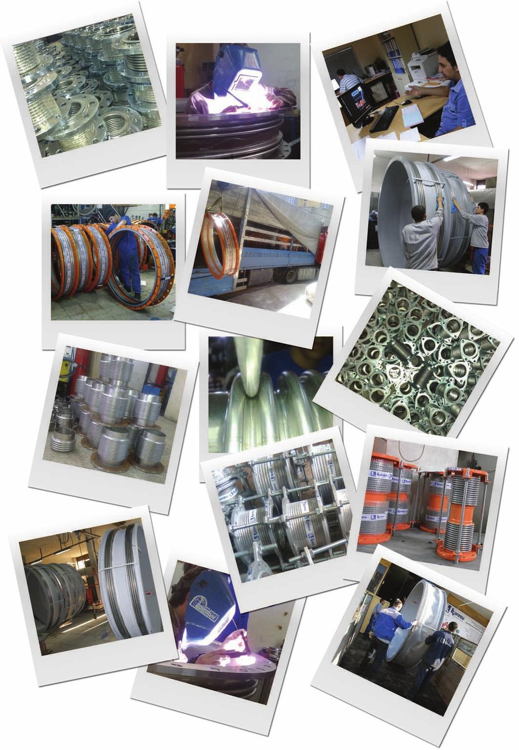
 KARASU has started is operation in 1991 under the leadership of its founder Ismet KARASU (1944 2006 ) in order to make contributions to the sector of industrial production in Turkey. Karasu Family producing
DESIGN CONSIDERATIONS
 PRESSURE THRUST DESIGN CONSIDERATIONS APPLICATIONS Intermediate Anchor An intermediate anchor is one which divides a pipeline into individual expanding pipe sections containing multiple expansion devices
Expansion & contraction
 Expansion & contraction All materials expand & contract with thermal change & pressure change. In case of piping systems, this dimension change can produce excessive stresses throughout the piping system
EXPANSION JOINT SELECTION GUIDE
 EXPANSION JOINT SELECTION GUIDE The proper selection and application of an expansion joint is the determining factor in its operation and life. Improper selection and application will lead to problems
- METALLIC EXPANSION JOINTS
 EXPANSION JOINTS FOR PIPING SYSTEM - METALLIC EXPANSION JOINTS - NON METALLIC EXPANSION JOINTS EXPANSION JOINTS FOR PIPING SYSTEM - METALLIC EXPANSION JOINTS - NON METALLIC EXPANSION JOINTS - EXPANSION
Introduction to Bellows Why bellows are used in Piping System?
 Introduction to BELLOWS http://www.sigmaflexeng.com http://www.sigmaflexeng.com Manufacturers of Expansion Joints & Flexible Metal Hose Assemblies Reg. Office & Factory: 865/2 GIDC INDUSTRIAL ESTATE, MAKARPURA,
PRODUCT CATALOGUE. PisaFlex is Mexico s premier manufacturer of metallic expansion joints and braided hose assemblies.
 PRODUCT CATALOGUE PisaFlex is Mexico s premier manufacturer of metallic expansion joints and braided hose assemblies. PisaFlex is qualified to Manufacture product to ASME U Stamp. PISAFLEX / PRODUCT CATALOGUE
A joint reliance. SJT series METAL EXPANSION JOINT SJT-0107
 A joint reliance SJT series METAL EXPANSION JOINT S J T SJT-0107 SJT series METAL EXPANSION JOINT FEATURES Bellow Expansion Joints are employed in piping systems to absorb differential thermal expansion
PIPINGSOLUTIONS, INC.
 Piping Stress Analysis Where do I start? The following information will take you step-by-step through the logic of the data collection effort that should occur prior to beginning to model a piping system
A LAYMAN S GUIDE TO BELLOWS AND EXPANSION JOINTS
 A LAYMAN S GUIDE TO BELLOWS AND EXPANSION JOINTS Why use them? Bellows and expansion joints are used in a wide variety of applications to absorb vibration and thermal movement in pipework, pumps, turbines,
UNIVERSAL TIED EXPANSION JOINTS
 UNIVERSA TIED EXPANSION JOINTS Scan this QR 64 ANSI DIN EN +600 C The movements occured in two directions can only be absorbed by using Epansion Joints. Universal tied expansion joints are made up of two
Expansion Joint. Ball Joint Flexible Joint
 Ball Joint Flexible Joint 255 Selection Ball Joint Selection Flexible Joint Selection 0.98 1.0 2.0 274 274 276 276 275 275 EB-1J EB-2J ES-10 ES-11 EB-11 EB-12 Type Bellows Sleeve Max. Pressure (MPa) 10
UNIVERSAL TYPE EXPANSION JOINT-UN TIED (MUN)
") SINGLE TYPE EXPANSION JOINT-UN TIED (MSN) The simplest form of expansion joint, of single bellows construction, designed to absorb all of the movements of the pipe section in which it is installed. According
SINGLE TYPE EXPANSION JOINT-UN TIED (MSN) The simplest form of expansion joint, of single bellows construction, designed to absorb all of the movements of the pipe section in which it is installed. According
EXPANSION JOINT & FLEXIBLE PRODUCT
 EXPANSION JOINT & FLEXIBLE PRODUCT B. TERAL EXPANSION JOINT MEGAFLEXON standard lateral expansion joints are available in two designs. The light design, type MLW, MLF, has tie rods which are secured to
Platinum Series FEATURES: Up to 16 Stainless Steel Plies
 Maximum Vibration Absorption Longest Cycle Life Soft Spring Rate = Ease of Installation Maximum Safety Platinum Series Series 151-1215 Welded Fixed Flange Series 150-TR-2115 Van Stone Floating Flange Keflex
Flanged. Standard Single Hinge. Product Nº : SHF/16/001. For more information please call our sales engineers on
 Product Nº : SHF/16/001 Standard Single Hinge Flanged Design ConDitions Max. Design Pressure 16 Bar Max. Design Temperature 300ºC Test Pressure Bellow Options End Fittings and Brackets Options Optional
expansion joints rubber bellows hoses stress analysis
 expansion joints rubber bellows hoses stress analysis expansion joints rubber bellows hoses stress analysis Contents EXPANSION JOINTS UNRESTRAINED EXPANSION JOINTS Introduction 3 Axial Expansion Joint
Expansion Joints Guide Module 2a - Axial Expansion Joints General - Standard Program (EFB) - Installation Instructions
 - Installation Instructions") Expansion Joints Guide Module 2a - Axial Expansion Joints General - Standard Program (EFB) - Installation Instructions BOA Expansion Joints Guide Expansion Joints Guide Summary Module 2a 1 AXIAL EXPANSION
Expansion Joints Guide Module 2a - Axial Expansion Joints General - Standard Program (EFB) - Installation Instructions BOA Expansion Joints Guide Expansion Joints Guide Summary Module 2a 1 AXIAL EXPANSION
MICROFLEX INDUSTRIAL ABOUT DISCLAIMER
 ABOUT MICROFLEX INDUSTRIAL ABOUT Founded in 1975 by Josif and George Atanasoski, Microflex Inc. has become a global provider of high quality flexible metal products serving the automotive, petrochemical,
DIN EN : (E)
") DIN EN 13480-3:2017-12 (E) Metallic industrial piping - Part 3: Design and calculation Contents Page European foreword... 10 1 Scope... 12 2 Normative references... 12 3 Terms, definitions, symbols and
DIN EN 13480-3:2017-12 (E) Metallic industrial piping - Part 3: Design and calculation Contents Page European foreword... 10 1 Scope... 12 2 Normative references... 12 3 Terms, definitions, symbols and
expansion joints metal bellows Traditions Will Never Mean Limits. Form and Function. Anything Worth Doing is Worth Doing Right.
 Flexcomp Flexpress Bellowsflex Pumpflex BellowsXhaust Guideline Traditions Will Never Mean Limits. We understand that no customer s requirements are exactly the same. That our audience is targeted to engineers/designers
Expansion Joint Ball Joint Flexible Joint
 Ball Joint Flexible Joint -1 Step 0 Type/Structure/Features Please refer to this for structure and feature of Expansion Joint, Ball Joint, and Flexible Joint. Step 1 Selection Please look at the ID chart
Standard Metal Expansion Joints
 Standard Metal Expansion Joints MULTI-PLY CONSTRUCTION PROVIDES LONGER CYCLE LIFE SERIES-1 Triad Bellows Series-1 expansion joints are manufactured with multiple layers of heavier gauge T-321 s/s material
Dispositivos Flexibles S.A. de C.V. Metallic Expansion Joints
 Dispositivos Flexibles S.A. de C.V. Metallic Expansion Joints 1 Dispositivos Flexibles S.A. de C.V. Product Catalog Index Expansion Joint. What is an expansion joint? Types of Movement. Metallic Expansion
Copper Axial Expansion Joint
 For Technical Assistance and Sales Contact: FlexEJ Ltd Tel: +44 (0) 1384 881188 Email: sales@flexej.co.uk Fax: +44 (0) 1384 896875 Web: www.flexej.co.uk Section 4 Copper Axial Expansion Joint FlexEJ Small
Pre-Engineered Expansion Joint Products. Ordering Guide for. 15, 50, 150 & 300 psi
 Pre-Engineered Expansion Joint Products Ordering Guide for Pre-Engineered Expansion Joint Products 15, 50, 150 & 300 psi H o s e M a s t e r I n c. Our Company Hose Master Inc. is the premier manufacturer
Flexider FLUID CATALYTIC CRACKING UNIT EXPANSION JOINTS INDUSTRIAL. An IMCI Company
 FLUID CATALYTIC CRACKING UNIT EXPANSION JOINTS An IMCI Company CALL TOLL FREE: 1-888-979-FLEX Design and Engineering specializes in the custom design and engineering of FCCU expansion joints. These items
Submitted by: Sr. Engineer. Sr. Product Engineer. Product Engineer. Director Power Market Sales. Approved by: Director of Engineering
 Modeling Victaulic Couplings in Piping System Stress Analysis Programs By David Hudson, BSME Gary Trinker, BSME Osama AlMasri, BSME Dan Christian, BSMC Victaulic Engineering Services Department May 2012
Style 233-L & 234-L Rubber Joints
 Style 33-L & 3-L Rubber Joints Style 33-L Rubber s are designed for piping systems that experience large lateral offsets due to settlement. The Style 33-L is a low profile triple arch design with a built-in
ARMYLOR PTFE BELLOWS & COMPENSATORS
 ARMYLOR PTFE BELLOWS & COMPENSATORS CONTENT MERSEN ANTICORROSION EQUIPMENT p.2 RANGE OF BELLOWS & COMPENSATORS p.3 REFERENCES p.4 TECHNICAL SPECIFICATIONS p.5-6 BELLOW FLANGES p.7 COMPENSATOR FLANGES p.8
MONOVAR is the energy dissipating valve.
 MONOVAR is the energy dissipating valve. Features Extremely simple design (patented) Excellent cavitation characteristics Very accurate flow or pressure control Manual or automatic control Suitable for
Townsend Bearings. Rosta Tensioner Devices. Revision 1
 Townsend Bearings Rosta Revision 1 Tensioning Technology Chain Tensioning Roller chains are power transmission components with positive transmission which, by virtue of their design are subject, depending
Compact Modules. with ball screw drive and toothed belt drive R310EN 2602 ( ) The Drive & Control Company
 The Drive & Control Company") with ball screw drive and toothed belt drive R310EN 2602 (2007.02) The Drive & Control Company Bosch Rexroth AG Linear Motion and Assembly Technologies Ball Rail Systems Roller Rail Systems Linear Bushings
with ball screw drive and toothed belt drive R310EN 2602 (2007.02) The Drive & Control Company Bosch Rexroth AG Linear Motion and Assembly Technologies Ball Rail Systems Roller Rail Systems Linear Bushings
Flow Meter Terminal Boxes
 Shutter Flow Meter Terminal Boxes Shutter Flow meter Terminal boxes 02 07 11 1 Shutter Valve DAROC Description and general specifications Production range and operating conditions Operation Installation,
Spark arrestor type C
 Spark arrestor type C Spark arrestors of type C are especially designed for applications in exhaust systems with high demands regarding explosion risk. The spark arrestors are to be mounted in the flues
Comflex Metallic Expansion Joints Engineering Guide
 Comflex Metallic Expansion Joints Engineering Guide High Performance Expansion Joints Comflex Metallic Expansion Joints Engineering Guide Contents 1. Introduction 3 2. Manufacturing methods 4 3. Glossary
PRECISION BELLOWS COUPLINGS
 PRECISION BELLOWS COUPLINGS Bellows couplings are used where precise rotation, high speeds, and dynamic motion must be transmitted. They exhibit zero backlash and a high level of torsional stiffness, offering
Spring hangers, spring supports
 Spring hangers, spring supports 2 spring Spring hangers, supports PRODUCT 2 GROUP Spring hangers, spring supports Contents Page Field of application...2.1 Overview of spring hangers and spring supports...2.3
3.1 Stainless steel exhaust bellows
 3.1 Stainless steel exhaust bellows There are two basic types of expansion bellows singles and doubles, and their purpose is to absorb the movement in any pipework run that is fixed between two fixed points.
PATENT: ARTICULATED RHOMBIC PRISM PISTON FOR THERMAL MACHINES Filed in Italy on 18/11/2008 N TO 2008 A Inventor: Vittorio Scialla -
 PATENT: ARTICULATED RHOMBIC PRISM PISTON FOR THERMAL MACHINES Filed in Italy on 18/11/2008 N TO 2008 A 000847 Inventor: Vittorio Scialla - Nationality: italian - Resident: Via Cibrario 114, Torino (TO),
FAX: SPECIAL APPLICATION HOSES, METAL & TEFLON HOSES
 Large Bore Teflon Fittings Selection Pipe Thread (NPT) Style 03 Flanges Lap Joint Flange Style 12 Shown with epoxy coated steel flange Cam and Groove Female Swivel Type Style 16 Also available Teflon Encapsulated
CARBONE LORRAINE CHEMICAL EQUIPMENT DIVISION PTFE Bellows & Compensators ARMYLOR
 CARBONE LORRAINE CHEMICAL EQUIPMENT DIVISION PTFE Bellows & Compensators ARMYLOR Contents 3 Carbone Lorraine 4 Range of Bellows & Compensators 5 References 6 7 Technical specifications 8 Bellow flanges
2. Motion relationships and torques
 2. Motion relationships and torques 2.1 Rotation angle of a single joint as a function of defl ection angle ß 1 Input rotation angle 2 Output rotation angle If a single joint is deflected by angle ß and
POLYFLURON PTFE expansion joints
 POLYFLURON PTFE expansion joints Characterized by exceptional safety and long service life Expansion joints with white and antistatic black POLYFLURON liners POLYFLURON expansion joints have a unique combination
Fixed Points. 7.i
 Products 7.0 Basic Assemblies 7.1 Trestle Arrangement (Assembly and Scope of Delivery) 7.2 Soundproof Fixed Points 7.3 Procedure for designing of trestle arrangement 7.4 Type tested static for trestle
h Technical Product Data CC Pressure Pipe Systems
 h Technical Product Data CC Pressure Pipe Systems Amiblu Holding GmbH All rights reserved. Publication: 09/2018 This version replaces all previous versions. For all current data please visit our website
Teguflex. Expansion joints TEGUFLEX. Expansion joints. TRELLEBORG FLUID HANDLING SOLUTIONS
 Teguflex Expansion joints TEGUFLEX Expansion joints www.trelleborg.com/fr/expansion-joints TRELLEBORG FLUID HALING SOLUTIONS Expansion joints Teguflex Functions and advantages Compensate for thermal elongation.
B.TECH III Year I Semester (R09) Regular & Supplementary Examinations November 2012 DYNAMICS OF MACHINERY
 Regular & Supplementary Examinations November 2012 DYNAMICS OF MACHINERY") 1 B.TECH III Year I Semester (R09) Regular & Supplementary Examinations November 2012 DYNAMICS OF MACHINERY (Mechanical Engineering) Time: 3 hours Max. Marks: 70 Answer any FIVE questions All questions
1 B.TECH III Year I Semester (R09) Regular & Supplementary Examinations November 2012 DYNAMICS OF MACHINERY (Mechanical Engineering) Time: 3 hours Max. Marks: 70 Answer any FIVE questions All questions
Product overview. 10 Bosch Rexroth Corporation Compact Modules R310A 2602 ( ) Compact Modules CKK. Compact Modules with ball screw drive (CKK)
 Compact Modules CKK. Compact Modules with ball screw drive (CKK)") 10 Bosch Rexroth Corporation R310A 2602 (2008.09) CKK with ball screw drive (CKK) Product overview are precision, ready-to-install linear motion systems characterized by their high performance and compact
10 Bosch Rexroth Corporation R310A 2602 (2008.09) CKK with ball screw drive (CKK) Product overview are precision, ready-to-install linear motion systems characterized by their high performance and compact
LM Guide Actuator KR. For details, visit THK at CATALOG No E. Product information is updated regularly on the THK website.
 LM Guide Actuator KR For details, visit THK at www.thk.com Product information is updated regularly on the THK website. CATALOG No.209-10E Integrated LM Guide and all Screw High-rigidity / High-precision
The gear boxes can be run at the same speeds as the actuator models. Do not exceed torque ratings.
 1. What is the lifting torque required? The lifting torque for a single actuator depends on the load, the worm gear ratio, type of screw (machine cut or ball screw) and the pitch of the lifting screw.
mechanical coupling system
 mechanical coupling system R Since 1981 Depend-O-Lok has offered engineers, contractors, OEM s and system owners an improved pipeline coupling system. Depend-O-Lok products offer strength, longterm reliability,
Theory of Machines. CH-1: Fundamentals and type of Mechanisms
 CH-1: Fundamentals and type of Mechanisms 1. Define kinematic link and kinematic chain. 2. Enlist the types of constrained motion. Draw a label sketch of any one. 3. Define (1) Mechanism (2) Inversion
SPRING HANGERS, SPRING SUPPORTS PRODUCT GROUP
 SPRING HANGERS, SPRING SUPPORTS PRODUCT GROUP VARIABLE SPRING ELEMENTS CONTENTS PAGE 0 Spring hangers, spring supports, sway braces.1 Load table for spring hangers, spring supports and other spring elements.3
Marine Engineering Exam Resource Review of Couplings
 1. What are rigid couplings used for? Used to join drive shafts together. True alignment and rigidity are required. Example Drive shafts and production lines, bridge cranes, solid shaft that needs to be
Installation, Operation & Maintenance Manual
 Installation, Operation & Maintenance Manual Style 240/242 Date: 2431 North Wigwam Dr. Stockton, CA 95205 Phone: 800-344-3246 Fax: 209-943-0242 Email: sales@procoproducts.com Table of Contents 1.0 Introduction:
CH.4 Basic Components of Hydraulic and Pneumatic System/16 M HAP/17522/AE5G
 Content : 4.1 Hydraulic and Pneumatic actuators. 10 Marks Hydraulic Actuators - Hydraulic cylinders (single, double acting and telescopic) construction and working, Hydraulic motors (gear and piston type)
Grupa Powen-Wafapomp SA. Pumps for Power and Heat Supplying Industries catalogue
 0 Grupa Powen-Wafapomp SA Pumps for Power and Heat Supplying Industries 2017 catalogue Contents 2 Basic pumps Supply pumps Z YS 4 10 Condensate pumps K i WK 20 Cooling water pumps D P 26 32 Hot water pumps
FLANGE. Flanges used for
 FLANGE FLANGE Flanges with rating class designations 150, 300, 400, 600, 900, 1500, and 2500 in sizes NPS 1 2 through NPS 24 ASME B16.5: Pipe Flanges and Flanged Fittings (NPS 24 ) ASME B16.47: NPS 26
ORDERING: Specify size, figure number, description, nominal pipe size or special O.D. and C-to-C dimension. C - C LOAD lb.
 Fig. 2110 www.pipingtech.com/fig2110 Sway Strut with 4 of Adjustment Engineered spring supports option 1 option 2 ORDERING: Specify size, figure number, description, nominal pipe size or special O.D. and
Excellence in Metal Expansion Joints
 Excellence in Metal Expansion Joints 1 The Experience that counts! Established in 1963, KE-Burgmann s first export order in 1969 set the grounds for continuous growth and internationalization of the company.
SERIES ASM NEOPRENE/EPMD FLANGED SINGLE SPHERE CONNECTOR CONNECTORS. Pressures to 225 PSIG (15.51 barg) Temperatures to 230ºF (110ºC)
 Temperatures to 230ºF (110ºC)") CONNECTORS APPLICATIONS Process Industry Weak Acids Alkalies Compressed Air Pulp & Paper MODELS ASM - Flanged Connection OPTIONS Control Rods Oil & Gas Water & Waste Pump suction & discharge Sea water
CONNECTORS APPLICATIONS Process Industry Weak Acids Alkalies Compressed Air Pulp & Paper MODELS ASM - Flanged Connection OPTIONS Control Rods Oil & Gas Water & Waste Pump suction & discharge Sea water
FLEXIBLE COUPLINGS Coupling importance For transmission Selection Absorption of shaft misalignment and loads Kinematic precision Rotation speed
 FLEXIBLE COUPLINGS Coupling importance A large number of mechanical installations involve the problem of transmitting movement between the machine shafts. The coupling is the simplest manner of achieving
Slotted nut NMG. Housing nut GWR. Bosch Rexroth AG. for economical constructions. a min. 0,3. M A = tightening torque of slotted nut.
 R310EN 3301 (2009.08) Precision Ball Screw Assemblies Bosch Rexroth AG 113 Slotted nut NMG for economical constructions B D d d1 b M A = tightening torque of slotted nut a min. 0,3 Polyamide insert Designation
MICROFLEX MX EXPANSION JOINTS
 EXPANION JOINT X EXTERNAY PREURIZED THE X DEIN ADVANTAE icroflex s X expansion joints are designed with an uncompromising standard of quality for years of maintenance free operation in distribution pipelines
STAINLESS STEEL EXPANSION JOINT, TYPE RFA-S
 STAIESS STEEL EXPANSION JOINT, TYPE RFA-S A stainless steel expansion joint with carbon steel flanges for the use in thermal oil pipe systems. For applications where a thermal expansion of the piping has
ENGINEERED SOLUTIONS For Industrial & HVAC Applications
 ENGINEERED SOLUTIONS For Industrial & HVAC Applications www.flexonics.com Contents Introduction... 1 Engineering Information... 2 Expansion Joint Design Basics... 3 Applications Engineering... 6 Standard
LBTC Series Positive Displacement Rotary Vane Flow Meters
 LBTC Series Positive Displacement Rotary Vane Flow Meters Summary LBTC Series positive displacement rotary vane flow meters are independently designed and manufactured by our company on the base of absorbing
Ford Fabricated Steel Products
 Ford Fabricated Steel Products Section N2 12/2000 The Ford Meter Box Co., Inc. 775 Manchester Avenue, P.O. Box 443, Wabash, Indiana, USA 46992-0443 Telephone: 219/563-3171 FAX: 1-800-826-3487 Overseas
Comflex Metallic Expansion Joints
 Comflex Metallic Expansion Joints High Performance Expansion Joint Technology Comflex Metallic Expansion Joints Introduction Metallic expansion joints are installed in piping systems to absorb differential
High Speed Gears - New Developments
 High Speed Gears - New Developments by T. Oeeg Contents: 1. Introduction 2. Back to Back Test Bed 3. Radial Tilting Pad Bearings 3.1 Design 3.2 Test Results 3.3 Deformation Analysis 4. Axial Tilting Pad
Breakthrough in Linear Generator design
 Breakthrough in Linear Generator design Rotary Linear Generator (stroke-rotor generator) By Physicist Wolfhart Willimczik ABSTRACT The law of inductions demands high speed for the moveable electrical parts,
R10 Set No: 1 ''' ' '' '' '' Code No: R31033
 R10 Set No: 1 III B.Tech. I Semester Regular and Supplementary Examinations, December - 2013 DYNAMICS OF MACHINERY (Common to Mechanical Engineering and Automobile Engineering) Time: 3 Hours Max Marks:
BI-ECCENTRIC Disc Retention Valve
 05/11/2015 - Oscillating disc retention valve with dual eccentricity and straight seat. - Option of manufacturing WAFER type or with flange boring in accordance with customer requirements. - Distance between
MATERIAL FOR FIBRE OPTIC LINES. General C-bracket HSU trunnion type, forged, for aluminium based OPGW conductors...
 153 Contents General.................................................................................................. 154 C-bracket.................................................................................................
3. BEARING ARRANGEMENT DESIGN
 3. BEARING ARRANGEMENT DESIGN 3.1 GENERAL PRINCIPLES OF ROLLING BEARING ARRANGEMENT DESIGN Rotating shaft or another component arranged in rolling bearings is guided by them in radial as well as in axial
PVE /117 ED VARIABLE DISPLACEMENT VANE PUMPS WITH DIRECT PRESSURE ADJUSTMENT SERIES 30 OPERATING PRINCIPLE TECHNICAL SPECIFICATIONS
 14 110/117 ED PVE VARIABLE DISPLACEMENT VANE PUMPS WITH DIRECT PRESSURE ADJUSTMENT OPERATING PRINCIPLE The PVE pumps are variable displacement vane pumps with direct pressure regulator. The pump group
INDUSTRIAL HOSES - compensators
 Working parameters of rubber expansion joints The parameters of rubber compensators given in the tables (, temperature and displacement) are the maximum values and they must not occur simultaneously. The
SCOPE OF WORK WASTEWATER TREATMENT PLANT THE WORLD LEADER IN PIPE JOINING SOLUTIONS
 SCOPE OF WORK WASTEWATER TREATMENT PLANT THE WORLD LEADER IN PIPE JOINING SOLUTIONS THE VICTAULIC DIFFERENCE HOUSING GROOVE GASKET BOLT/NUT GROOVE GROOVED PIPE JOINING TECHNOLOGY How does it work? The
Series 3500 Externally Pressurized Expansion Joints Catalog 574 H
 Series 3500 Externally Pressurized Expansion Joints Catalog 57 H 500 Laminated Bellows Expansion J Series 3500 on Joints Externally Pressurized Expansion Joints Standard Designs Sizes " through ", 50 &
AT 2303 AUTOMOTIVE POLLUTION AND CONTROL Automobile Engineering Question Bank
 AT 2303 AUTOMOTIVE POLLUTION AND CONTROL Automobile Engineering Question Bank UNIT I INTRODUCTION 1. What are the design considerations of a vehicle?(jun 2013) 2..Classify the various types of vehicles.
Ball. Ball cage. Fig.1 Structure of Caged Ball LM Guide Actuator Model SKR
 Caged all LM Guide Actuator Model Inner block all screw shaft Grease nipple Outer rail all cage all Structure and Features Fig.1 Structure of Caged all LM Guide Actuator Model Caged all LM Guide Actuator
SINGLE ACTING METRIC RANGE
 CONTENTS Page 2 General specifications Ram Style No. Female Rod Male Rod Pin Hole 3 Part Numbering System 4 Dimensions 5 Buckling Calculations 6 Buckling Force/ Graphs 7 Load Calculations 8 PBV Flow Chart
Metal Expansion Joint and Flexible Metal Hose
 KURO Metal Expansion Joint and Flexible Metal Hose www.kurbo.co.kr l www.winflex.co.kr Table of ontents Introduction to Kurbo 1 Metal Expansion Joints Kurbo ellows Type Metal Expansion Joint Typical omposition
RUBBER BELLOWS TYPE 1A & 1S SERIES
 RUBBER BELLOWS TYPE 1A & 1S SERIES Description: Vibracoustics Ltd Reiflexa Bellows are made from various elastomers reinforced with high tensile textile or steel cords to provide the flexible elements
Expansion Joint Presentation
 Expansion Joint Presentation American BOA-Industrial Division Mailing Address: P.O. Box 1301, Cumming, GA 30028 Phone: 770.889.9400 Fax: 770.781.3968 Website: www.americanboa.com E-mail: sales@boa-us.com
RECEIVING AND INSPECTION EXAMINE ALL COMPONENTS FOR POSSIBLE SHIPPING DAMAGE PRIOR TO INSTALLATION.
 Non-Welded Grease Duct Systems Installation, Operation, and Maintenance Manual FOR YOUR SAFETY TWO MAJOR CAUSES OF GREASE DUCT RELATED FIRES: (1) FAILURE TO MAINTAIN REQUIRED CLEARANCE (AIR SPACE) TO COMBUSTIBLE
Front-mounted equipment. Fitting front-mounted equipment
 Fitting front-mounted equipment Fitting front-mounted equipment This document describes a number of solutions for fitting front-mounted equipment. More information is available in the document Limitations
Chapter 15. Inertia Forces in Reciprocating Parts
 Chapter 15 Inertia Forces in Reciprocating Parts 2 Approximate Analytical Method for Velocity and Acceleration of the Piston n = Ratio of length of ConRod to radius of crank = l/r 3 Approximate Analytical
Continuously Variable Transmission
 Continuously Variable Transmission TECHNICAL FIELD The present invention relates to a transmission, and more particularly, a continuously variable transmission capable of a continuous and constant variation
Metrovick F2/4 Beryl. Turbo-Union RB199
 Turbo-Union RB199 Metrovick F2/4 Beryl Development of the F2, the first British axial flow turbo-jet, began in f 940. After initial flight trials in the tail of an Avro Lancaster, two F2s were installed
Metal Bellows Design Guide
 The following definitions are provided to assist in part selection and customization to meet engineering design requirements and objectives. The definitions in this design guide are related to columns
SUSPENSION 04 CLAMPS
 SUSPENSION CLAMPS 04 4 SUSPENSION CLAMPS 57 Contents General... 58 Suspension clamp trunnion type, forged,... 63 Suspension clamp trunnion type, forged, with bigger angle of deflection, for aluminium based
Precision Modules PSK
 Precision Modules PSK 2 Bosch Rexroth AG Precision Modules PSK R999000500 (2015-12) Identification system for short product names Short product name Example:: P S K - 050 - N N - 1 System = Precision Module
Table of Contents Industrial Shock Absorber
 Table of Contents Industrial Shock Absorber Page Technical informations 4 Survey 16 Non-adjustable Shock Absorber Type SA 10 N, SA 10 SN, SA 10 S2N 20 Type SA 12N, SA 12 SN, SA 12 S2N 22 Type SA 14, SA
Sibre All Steel Couplings
 Overview Coupling is device to transmit torque from driving side to driven side and also has function of compensation of axial,radial,angular misalignment which generated by manufacturing, installation
IGP /117 ED INTERNAL GEAR PUMPS SERIES 10 OPERATING PRINCIPLE TECHNICAL SPECIFICATIONS HYDRAULIC SYMBOL
 00/7 ED IGP INTERNAL GEAR PUMPS OPERATING PRINCIPLE IGP pumps are volumetric displacement pumps with internal gears, available in five sizes, each divided into a range of different displacement. The pumps
10/29/2018. Chapter 16. Turning Moment Diagrams and Flywheel. Mohammad Suliman Abuhaiba, Ph.D., PE
 1 Chapter 16 Turning Moment Diagrams and Flywheel 2 Turning moment diagram (TMD) graphical representation of turning moment or crank-effort for various positions of the crank 3 Turning Moment Diagram for
Engineering Data Tensioner Arms idler Sprocket Sets Idler Roller Pulley Sets
 CHAIN & PULLEY TENSIONERS Engineering Data Tensioner Arms idler Sprocket Sets Idler Roller Pulley Sets ENGINEERING DATA TENSIONING TECHNOLOGY Chain & V-Belt Tensioning Roller chains are power transmission
BEARINGS The lower bearing assemble is constructed to allow continuous operation when fully submerged in wastewater.
 GENERAL SPECIFICATION INTENT The equipment to be supplied by manufacturer includes the screw pumps, support for the drive unit, profile plates, motors, gearboxes, couplings, guards, upper and lower bearing