Submitted by: Sr. Engineer. Sr. Product Engineer. Product Engineer. Director Power Market Sales. Approved by: Director of Engineering
|
|
|
- Katrina Tyler
- 6 years ago
- Views:
Transcription
1 Modeling Victaulic Couplings in Piping System Stress Analysis Programs By David Hudson, BSME Gary Trinker, BSME Osama AlMasri, BSME Dan Christian, BSMC Victaulic Engineering Services Department May 2012 Submitted by: Sr. Engineer Sr. Product Engineer Product Engineer Director Power Market Sales Approved by: Director of Engineering VICTAULIC IS A REGISTERED TRADEMARK OF VICTAULIC COMPANY 2011 VICTAULIC COMPANY. ALL RIGHTS RESERVED WP Rev. B 3/19/2013
2 Modeling and Analysis of Piping System Designs With Victaulic Rigid or Flexible Couplings INTRODUCTION Victaulic grooved mechanical couplings have been used to join pipe since 1925 on diverse piping systems in a variety markets including; power generation, oilfield/refinery, chemical, mining, alternative fuels, clean water, general industrial, PHA and fire protection. The use of Victaulic couplings does not create a need for stress analysis modeling; however, the couplings can be modeled into systems when there is a design requirement. Various customers and consulting engineering firms have requested information regarding how to model Victaulic couplings in stress analysis software or information regarding product performance data so that they can analyze Victaulic systems as they do with welded systems. This document presents methodology on how to incorporate the characteristics of Victaulic grooved mechanical couplings into stress analysis programs. Victaulic contracted the services of the Worley Parsons Group, a global consulting engineering firm, to verify the proposed approach for modeling Victaulic rigid couplings in piping systems was consistent with industry standards for stress analysis software,. This study verified the suitability of CAESAR II stress analysis software for modeling and analysis of Victaulic rigid couplings. Included herein is a recommended modeling technique and stress analysis models for various piping configurations. The examples in this document range in pipe sizes from 2" (50mm) through 24" (600mm) with a temperature differential ( T) of 150 F (83.3 C) from ambient, but the methodology is consistent for other conditions as well. The stress analysis results from these piping configurations utilizing Victaulic couplings were then compared to the stress analysis results from these configurations utilizing standard butt welded construction. It was concluded that with minor input changes, the stress analysis program is a useful tool in analyzing Victaulic systems, producing results in a format similar to piping systems with a welded system construction. VICTAULIC RIGID and FLEXIBLE COUPLINGS Understanding the design features of Victaulic rigid and flexible couplings is the first step. Victaulic grooved couplings provide a permanent pipe connection which can withstand full pressure thrust loads at their maximum rated working pressure. Victaulic rigid couplings positively clamp the pipe to create a rigid joint, so axial movement and deflection are eliminated. They are particularly useful on risers, mechanical rooms, horizontal runs with numerous branches and other areas where flexibility is not required. Proper rigid coupling installation provides system behavior characteristics similar to those of other rigid systems, in that all piping remains strictly aligned and is not subject to axial or angular movement during operation. For this reason, systems installed with Victaulic rigid couplings utilize support techniques identical to those used in welded systems. Victaulic rigid couplings are designed to provide rigidity for hanger spacing


3 requirements in accordance with ASME B31.1 Power Piping Code, ASME B31.3 Process Piping Code, ASME B31.9 Building Services Piping Code and NFPA 13 Sprinkler Systems Code. Grooved Coupling Style 07 Rigid Style W07 Rigid Victaulic flexible couplings permit controlled pipe movement within the couplings while they maintain a positive seal and self-restrained joint. This is achieved because the coupling key section engages but "floats" in the groove. The design allows for expansion, contraction and deflection generated by thermal changes, building or ground settlement, and seismic activity. Pipe movement accommodation with Victaulic flexible couplings will minimize the stresses that can be generated by this movement. Victaulic flexible couplings also have superior vibration attenuation characteristics. Experience has shown that most designers utilize all rigid couplings except where the design features of flexible couplings can be incorporated to achieve optimal design advantage in areas such as those mentioned above. When both flexible and rigid couplings are utilized, the system designer can optimize hanger spacing, eliminate expansion loops and flex connectors and incorporate rigidity and flexibility where desired. A variety of benefits are provided to the system designer, installer and owner, which results in the most reliable system for most applications and makes Victaulic's grooved method the best choice for joining pipe. VICTAULIC ALLOWABLE COUPLING JOINT LOADS PRODUCT DESIGN GUIDELINES Pipe stress analysis software is typically designed to analyze welded piping systems in accordance with standard industrial piping codes. The design capabilities of grooved mechanical couplings are not presently included in these software programs. Victaulic
4 has developed Product Design Guidelines (PDG) to provide some of the critical input data changes for these programs and the allowable coupling loads for rigid couplings to compare with the output load data from these stress analysis programs. Contact Victaulic to request the PDG for the size/style of Victaulic coupling used in your system analysis. VICTAULIC RIGID COUPLING SYSTEM ANALYSIS For Systems installed with Victaulic rigid couplings, the allowable coupling loads document (Victaulic PDG) provides the allowable coupling joint loads. There are a few differences in the input parameters for these rigid couplings versus welded joints discussed in this document such as torsional stiffness, stress intensification factor and flexibility factor. Rigid couplings have limited torsional stiffness that is difficult to numerically define or describe as it is dependent upon a multitude of factors, primarily the friction between the coupling and the pipe groove. For system stress analysis, Victaulic suggests a stress intensification factor (SIF) of 2.3 as this is used for threaded joints and simulates a worst case condition, and a flexibility factor of K=1 which is actually the program default setting for welded joints. Victaulic also suggests that the torsional resistance be set identical to welded systems for single plane systems where there are no torsional loads imparted on the pipe joints. On multi-planar systems, where a torsional load may cause rotation within a coupling, the rotational "Gap" on the pipe axis (RX) be set at 1 (1 degree), see the example under the modeling section of this paper. Fitting and valve connections shall be treated as standard wall pipe, provided of course that the piping they are being joined with is standard wall. After changing these input criteria the stress analysis software would be run and the loads calculated by the software would then be compared to the allowable coupling loads tabulated in the Victaulic PDG document previously referenced. If the calculated loads are equal to or less than the allowable loads published, then the use of the couplings in the system as designed is acceptable. If the calculated stresses exceed these published loads, then the piping layout or support method would need to be modified and the program re-run or Victaulic flexible couplings could be incorporated to accommodate the piping movement in these high stress areas. VICTAULIC FLEXIBLE COUPLING SYSTEM ANALYSIS For systems installed with flexible couplings or where flexible couplings are incorporated into a system installed with rigid couplings to reduce the calculated loads, the analysis for the piping section installed with the flexible couplings becomes geometry based. Victaulic flexible couplings allow for a controlled amount of linear and angular movement. The system design/layout must be such that these movement values are not exceeded. The flexible couplings allow this free range of movement so metal to metal "lock up" in the joint does not exist. Therefore, the forces induced into the system are minimal when compared to the forces required to elastically deform pipe installed with rigid grooved couplings or welded connections.
5 Victaulic flexible couplings have mechanical strength that far surpasses other flexible devices such as rubber bellows, braided flex connectors or unrestrained mechanical joints. They create self restrained joints capable of restraining the pipes without anchors or thrust blocks as the full rated pipe joint working pressure. For example, Style 77 flexible couplings have working pressures greater than Style 07 rigid couplings and the Style W77 flexible couplings have the same working pressures as the Style W07 rigid couplings. Therefore, these flexible couplings will handle the same allowable loads as these rigid couplings. However, as stated above, the goal is not to exceed the flexible coupling's movement capabilities so the analysis remains as geometry based. An example of the geometry based analysis may be found in Appendix A. MODELING VICTAULIC COUPLINGS IN CAESAR II The objective of the study was to provide a method for using CAESAR II modeling techniques for Victaulic rigid couplings comparable to the method for butt welded construction. Although CAESAR II does not have a specific modeling function for Victaulic couplings, it does contain a modeling feature the restraint CNODE which can be used for this purpose. The resulting output load values are compared to the Victaulic published maximum rigid coupling allowable loads as found in Victaulic PDG s. It should be noted that this modeling technique is also applicable to Victaulic flexible couplings as the axial gap and angular offset characteristics of the flexible coupling can be modeled and analyzed. However, piping systems are installed mainly with rigid couplings, with flexible couplings only being utilized where the allowable load capability of the rigid couplings has been exceeded or for other design benefits such as vibration attenuation at equipment connections, accommodation of piping misalignment, building settlement, equipment nozzle movements and seismic movement. In order to define the Victaulic rigid coupling as a restraint in CAESAR II, the restraint NODE/CNODE (node/connecting node) model input fields are used. The NODE/CNODE model ties a fixed or restrained node at one pipe end to the next pipe end with associated degrees of freedom as inputted. This itemizes the loads on the rigid coupling as well as allows the user to easily filter a restraint report to review only the loads at the rigid coupling locations for the defined load cases. The below coupling diagram and CAESAR II NODE/CNODE input tables are shown to illustrate the input criteria. Victaulic rigid couplings in single plane system configurations should be modeled in CAESAR II as a restraint with all six degrees of freedom (X, Y, Z, RX, RY and RZ) defined as rigid. All inputs [the Gap, stiffness (Stif) and coefficient of friction (Mu)], should be left blank which allows the default program setting of a rigid connection to be applied. (Table 1) Alternatively, the coupling locations can be modeled as fixed points. (Table 2) In multi-planar system, five of the six degrees of freedom (X, Y, Z, RX, RY and RZ) should be defined as rigid, with the
6 rotational degree of freedom about the pipe axis as not rigid. The rotational resistance around the pipe axis (Rx in the below diagram) should have the Gap set at 1 (or higher) as this signifies a +/-1 degree of free rotation. The Stif and the Mu should remain empty, applying their default settings when recognizing the rotational (Gap) freedom of axial rotation. (Table 3) In effect this is a simple pipe end to pipe end (or fitting or valve) restraint model with no attachment to external supporting structures. With all six degrees of freedom defined, CAESAR II calculates the restraint loads the same as it calculates the typical node point forces and moments in a welded or flanged piping system. (Table 1) From: 10 Node: 20 CNode: 21 To: 20 Type: X Gap: Dx: "X1" Stif: Mu: Node: 20 CNode: 21 Type: Y Gap: Stif: Mu: Node: 20 CNode: 21 Type: Z Gap: Stif: Mu: Node: 20 CNode: 21 Type: RX Gap: Stif: Mu: From: 21 Node: 20 CNode: 21 To: 30 Type: RY Gap: Dx: "X2" Stif: Mu: Node: 20 CNode: 21 Type: RZ Gap: Stif: Mu:
7 In modeling and analysis of a single plane piping system, the rigid coupling was modeled simply as a single node point with the Victaulic specified SIF of 2.3 applied. The calculated output loads (FX, FY, FZ, MX, MY, MZ) for a node point are identical to the output loads of the CNODE restraint with all six degrees of freedom set to rigid. The only changes in output were the stress values due to the addition of the SIF factor of 2.3 included at the rigid coupling location. Alternatively, the coupling location can be modeled as an anchor, as its rigid characteristics make it an identical model. To do this, one would enter "ANC" in the input table as shown below. (Table 2) From: 10 Node: 20 CNode: 21 To: 20 Type: ANC Gap: Dx: "X1" Stif: Mu: From: 21 To: 30 Dx: "X2" For modeling and analysis of multi-plane piping layouts, the rigid coupling was modeled simply as a single node point with the Victaulic specified SIF of 2.3 applied. The calculated output loads (FX, FY, FZ, MX, MY, MZ) for a node point are identical to the output loads of the CNODE restraint with five of the six degrees of freedom set to rigid, with the exception being setting the axial torsional degree of freedom as not rigid, which reduces the resulting bending moments at the coupling locations. In effect, the pipe ends within the coupling were modeled as free to rotate about the pipe axis because these couplings have limited torsional stiffness as discussed previously. In the below example, "X" is the axis of the pipe, therefore the gap at RX is set to 1.
8 (Table 3) From: 10 Node: 20 CNode: 21 To: 20 Type: X Gap: Dx: "X1" Stif: Mu: Node: 20 Cnode: 21 Type: Y Gap: Stif: Mu: Node: 20 Cnode: 21 Type: Z Gap: Stif: Mu: Node: 20 Cnode: 21 Type: RX Gap: 1 Stif: Mu: From: 21 Node: 20 Cnode: 21 To: 30 Type: RY Gap: Dx: "X2" Stif: Mu: Node: 20 Cnode: 21 Type: RZ Gap: Stif: Mu: When modeling with the NODE/CNODE restraint definition, the loads across the rigid coupling are listed in the output of the Restraint Summary report. In this report, all restraint loads for the six degrees of freedom are listed for each rigid coupling location modeled. The forces and moments at each coupling location must then be manually compared to the maximum allowable rigid coupling loads. SUGGESTED MODELING TECHNIQUES 1. First model the piping system with supports as a conventional welded system with additional node points and restraints with CNodes added at the proposed Victaulic rigid coupling locations. 2. Apply a Stress Intensification Factor (SIF) of 2.3 to the node at the rigid coupling locations.
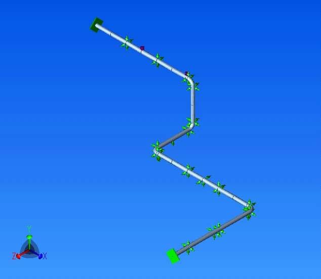
9 3a. For single plane systems, leave all inputs on the NODE/CNODE analysis table at their default values. (leave boxes in input table blank). Or, set the node as an anchor (ANC) and complete the analysis. 3b. For multi-plane systems, set the axial rotational resistance as not rigid by setting the Gap value at one (1). All the remaining inputs on the NODE/CNODE analysis table should be left at their default values. (leave boxes in input table blank) 4. Run the static analysis in CAESAR II and review the loads and stresses at the proposed rigid coupling locations. 5. Look for areas within the model with: - Rigid coupling location stresses in excess of 80% of code allowable. - Rigid coupling location axial end loads approaching or exceeding Victaulic rigid coupling allowable load values. - Rigid coupling location bending moments approaching or exceeding Victaulic rigid coupling allowable bending moment values. 6. This approach serves to identify areas within the model which may warrant support type and location revisions, pipe routing modifications to reduce loads and stresses to acceptable levels or the incorporation of Victaulic flexible couplings. RESULTS Following is a summary of the results for two typical piping runs under the design conditions set forth in the second paragraph of this papers introduction. The first (Configuration 4) was a three dimensional piping configuration having a Z bend with a riser. The following table for Configuration 4 is a combination of Victaulic provided couplings capabilities and CAESAR II generated data. As shown, the first four columns illustrate the rigid coupling's maximum rated working pressures and the maximum allowable end loads, shear loads and bending moments. The remaining columns illustrate the CAESAR II output results, which are the maximum loads generated at any node, (a worst case analysis). A comparison of these results shows that the rigid coupling allowable loads were not exceeded in all sizes.
10

11 The second piping configuration (Configuration 1) was a two dimensional, single plain Z bend with an expansion loop. As can be seen in the table for Configuration 1, the first four columns illustrate the rigid coupling's maximum rated working pressures and the maximum allowable end loads, shear loads and bending moments. The remaining columns illustrate the CAESAR II output results. A comparison of these results shows that the rigid coupling allowable loads were not exceeded in all sizes with the exception of the bending loads for sizes 8", 10" and 12". The specific location of the overstressed joints would be found in the detailed nodal stress analysis output provided by CAESAR II (not shown in this report). The overstressed bending loads have been highlighted in red on the Configuration 1 table.
12

13 As previously mentioned, when calculated loads exceed acceptable limits, the piping layout or support method needs to be modified. The program is then rerun with the new installation criteria. This "iterative" corrective action is consistent regardless of the type of pipe joint. Victaulic also offers the system designer an alternative of installing flexible couplings at select locations to accommodate piping movement in these high stress areas where acceptable loads are exceeded. Since modifying the piping layout or support method is common practice for welded systems, this document will only provide an example of the additional design option that Victaulic provides (how to incorporate flexible couplings in the areas where the rigid coupling allowable loads have been exceeded). A geometric analysis is shown in Appendix A to resolve the excess allowable loads calculated in Configuration 1 at the location of two rigid couplings on the short leg of the expansion loop. (As a general rule, Victaulic recommends the use of Flexible Couplings on expansion loops to reduce overall pipe stress in the loop and to decrease the loop size by 1/2 to 1/3 the weld loop size. In line expansion joints are also available. Please refer to Victaulic publication Calculating and Accommodating Pipe Line Thermal Growth.) CONCLUSION The methodology presented herein demonstrates how Victaulic couplings can be modeled into piping systems using existing stress analysis programs. With only minor input changes, the programs analyze Victaulic systems producing results comparable to welded piping systems.
14 Victaulic technical expertise is available, please feel free to contact for Victaulic for further information in applying the above methodology should questions arise.
15 APPENDIX A GEOMETRIC ANALYSIS USING VICTAUILC FLEXIBLE COUPLINGS The Configuration 1 example illustrates shows the length of pipe from the expansion loop to the anchor points on both sides to be 65' (19.8m). As the temperature increases by 150 F (83.3 C) each 65' (19.8m) section will experience an increase in length of.77" (19.6mm). 65' (19.8m) 65' (19.8m) As shown on the drawing, the perpendicular legs of the expansion loop (designed for welded piping) are 12' (3.6m) long. The perpendicular leg lengths were developed using the most common method for sizing welded expansion loops, as found in the ASHRAE Systems and Equipment Handbook. To Anchor 0.77" (19.6mm) To Anchor 12' (3.6m) Weld Construction The analysis using the same loop and Victaulic rigid couplings revealed an overstressed condition that can be resolved by increasing the lengths of the perpendicular legs or more easily, with the addition of a few strategically located Victaulic Flexible Couplings. 10" pipe size will be used as an example and incorporate the flexible couplings, as is the size that exceeded the rigid coupling allowable loads by the greatest amount and will, therefore, best demonstrate the advantage of the flexible coupling's deflection capability.
16 The design angle of deflection for Victaulic 10" Style 77 flexible couplings is.5 degrees when installed on roll grooved pipe. 1 This deflection can also be expressed in terms of deflection from centerline per unit length of pipe and this value for the 10" Style 77 flexible coupling is.105"/ft (9mm/m). The below diagram provides an illustration of the centerline offset over 1ft, 10ft, 1m and 10m of pipe due to this deflection, (the imperial and metric dimensions are not direct conversions). 10' [10m] 1' [1m] 0.105" [9mm] 1.05" [90mm] 0.5 Replacing the two rigid couplings on each 12ft (3.6m) long perpendicular leg of the expansion loop with flexible couplings will allow each leg to accommodate 1.26" (32mm)..105"/' x 12' = 1.26" (9mm/m x 3.6m = 32.4mm) As required by the system design parameters, each leg only needs to accommodate.77" (19.6mm). This gives the designer the option of just replacing the rigid couplings with flexible couplings or to take advantage of the full deflection capability of the two flexible couplings on each leg and reduce the leg lengths to 7.3' (2.19m)..77".105"/' = 7.3' (19.6mm 9mm/m = 2.18m) 1 The design angle of deflection for Victaulic Flexible couplings is derived by multiplying Victaulic's published maximum values by an installation safety factor. Victaulic recommends the maximum values be reduced by 50% for ¾" 3 ½" flexible couplings and by 25% for 4" and larger flexible couplings for designing purposes.
17 0.77" (19.6mm) To Anchor To Anchor 7.3' (2.18m) Two Flexible Couplings To demonstrate the full capability of incorporating flexible couplings into system changes in direction, a third (and preferred) option would be to replace the eight rigid couplings on the four elbows of the expansion loop with flexible couplings. Doubling the number of flexible couplings doubles the offset angle, resulting in the perpendicular leg lengths to be reduced to only 3.67' (1.09m), a tremendous material and space savings..77" 2(.105"/') = 3.67' (19.6mm 2(9mm/m) = 1.09m) 0.77" (19.6mm) To Anchor To Anchor 3.67' (1.09m) All Flexible Couplings As can be seen, the use of flexible couplings at system changes in direction can reduce the system footprint which may be very beneficial in areas with spacial constraints or when there are multiple parallel pipelines.
18 APPENDIX B Deflected Joints A normal force applied at a distance from the pipe joint creates a moment that causes pipe deflection to occur at a Victaulic flexible coupling. Similarly, when two pipes are assembled deflected with Victaulic Flexible Couplings, upon pressurization forces are created (see diagram below), which act to straighten the joint. This force applied at the same location, (or moment), is in an equal and opposite direction that would be required to deflect a straight joint. In situations where one pipe is restrained, the moment to cause deflection or to maintain a deflected joint may be approximated by the formula below. This moment was derived from balancing forces and moments in a free body diagram and does not take in to account any deflection of the "restrained" pipe between the restraint and the Victaulic coupling or the effects of friction. M = πpd 3 /8 Where: M = Moment p = Internal Pressure D = Outside Diameter At a given distance on the "unrestrained" pipe from the coupling, the force required to deflect or to maintain deflection of a joint is approximated by the formula below. F = M/L = πpd 3 /8L Where: F = Deflecting or Restraining Force p = Internal Pressure D = Outside Diameter L = Length from Centerline of Groove to Force (F)
19
PIPINGSOLUTIONS, INC.
 Piping Stress Analysis Where do I start? The following information will take you step-by-step through the logic of the data collection effort that should occur prior to beginning to model a piping system
Expansion & contraction
 Expansion & contraction All materials expand & contract with thermal change & pressure change. In case of piping systems, this dimension change can produce excessive stresses throughout the piping system
SCOPE OF WORK WASTEWATER TREATMENT PLANT THE WORLD LEADER IN PIPE JOINING SOLUTIONS
 SCOPE OF WORK WASTEWATER TREATMENT PLANT THE WORLD LEADER IN PIPE JOINING SOLUTIONS THE VICTAULIC DIFFERENCE HOUSING GROOVE GASKET BOLT/NUT GROOVE GROOVED PIPE JOINING TECHNOLOGY How does it work? The
Introduction to Bellows Why bellows are used in Piping System?
 Introduction to BELLOWS http://www.sigmaflexeng.com http://www.sigmaflexeng.com Manufacturers of Expansion Joints & Flexible Metal Hose Assemblies Reg. Office & Factory: 865/2 GIDC INDUSTRIAL ESTATE, MAKARPURA,
EXPANSION JOINT SELECTION GUIDE
 EXPANSION JOINT SELECTION GUIDE The proper selection and application of an expansion joint is the determining factor in its operation and life. Improper selection and application will lead to problems
A Recommended Approach to Pipe Stress Analysis to Avoid Compressor Piping Integrity Risk
 A Recommended Approach to Pipe Stress Analysis to Avoid Compressor Piping Integrity Risk by: Kelly Eberle, P.Eng. Beta Machinery Analysis Calgary, AB Canada keberle@betamachinery.com keywords: reciprocating
Riverhawk Company 215 Clinton Road New Hartford NY (315) Free-Flex Flexural Pivot Engineering Data
 Free-Flex Flexural Pivot Engineering Data") Riverhawk Company 215 Clinton Road New Hartford NY (315)768-4937 Free-Flex Flexural Pivot Engineering Data PREFACE Patented Flexural Pivot A unique bearing concept for applications with limited angular
Riverhawk Company 215 Clinton Road New Hartford NY (315)768-4937 Free-Flex Flexural Pivot Engineering Data PREFACE Patented Flexural Pivot A unique bearing concept for applications with limited angular
MAIN SHAFT SUPPORT FOR WIND TURBINE WITH A FIXED AND FLOATING BEARING CONFIGURATION
 Technical Paper MAIN SHAFT SUPPORT FOR WIND TURBINE WITH A FIXED AND FLOATING BEARING CONFIGURATION Tapered Double Inner Row Bearing Vs. Spherical Roller Bearing On The Fixed Position Laurentiu Ionescu,
Rules of Actuator and Guide Alignment in Linear Motion Systems
 Rules of Actuator and Guide Alignment in Linear Motion Systems By Gary Rosengren, Director of Engineering Tolomatic, Inc. About the Author Gary Rosengren is Director of Engineering at Tolomatic and has
THE VICTAULIC PIPING METHOD FOR ACCOMMODATING PIPE OFFSETS
 R GROOVED PIPING SYSTEMS DESIGN DATA 2.03 THE VICTAULIC PIPING METHOD FOR ACCOMMODATING PIPE OFFSETS 1. Pipe Offsets Victaulic flexible couplings offer the designer a method to accommodate offsets of pipe
Piping Stress Considerations and Practical Remedies to Overcome Nozzle Misalignment and Vibration Related Issue
 V th International Symposium on Fusion of Science & Technology, New Delhi, India, January 18-22, 2016 ID: 2016-ISFT-293 Piping Stress Considerations and Practical Remedies to Overcome Nozzle Misalignment
- METALLIC EXPANSION JOINTS
 EXPANSION JOINTS FOR PIPING SYSTEM - METALLIC EXPANSION JOINTS - NON METALLIC EXPANSION JOINTS EXPANSION JOINTS FOR PIPING SYSTEM - METALLIC EXPANSION JOINTS - NON METALLIC EXPANSION JOINTS - EXPANSION
Simulating Rotary Draw Bending and Tube Hydroforming
 Abstract: Simulating Rotary Draw Bending and Tube Hydroforming Dilip K Mahanty, Narendran M. Balan Engineering Services Group, Tata Consultancy Services Tube hydroforming is currently an active area of
DIN EN : (E)
") DIN EN 13480-3:2017-12 (E) Metallic industrial piping - Part 3: Design and calculation Contents Page European foreword... 10 1 Scope... 12 2 Normative references... 12 3 Terms, definitions, symbols and
DIN EN 13480-3:2017-12 (E) Metallic industrial piping - Part 3: Design and calculation Contents Page European foreword... 10 1 Scope... 12 2 Normative references... 12 3 Terms, definitions, symbols and
DESIGN CONSIDERATIONS
 PRESSURE THRUST DESIGN CONSIDERATIONS APPLICATIONS Intermediate Anchor An intermediate anchor is one which divides a pipeline into individual expanding pipe sections containing multiple expansion devices
A LAYMAN S GUIDE TO BELLOWS AND EXPANSION JOINTS
 A LAYMAN S GUIDE TO BELLOWS AND EXPANSION JOINTS Why use them? Bellows and expansion joints are used in a wide variety of applications to absorb vibration and thermal movement in pipework, pumps, turbines,
Expansion Joint. Ball Joint Flexible Joint
 Ball Joint Flexible Joint 255 Selection Ball Joint Selection Flexible Joint Selection 0.98 1.0 2.0 274 274 276 276 275 275 EB-1J EB-2J ES-10 ES-11 EB-11 EB-12 Type Bellows Sleeve Max. Pressure (MPa) 10
LTI Cooling Tower Drive Shafts
 LTI Cooling Tower Drive Shafts Highlights: Outstanding performance evolved from a helicopter heritage Designed specifically for cooling tower duty 100% fully integral carbon fiber epoxy construction. No
The gear boxes can be run at the same speeds as the actuator models. Do not exceed torque ratings.
 1. What is the lifting torque required? The lifting torque for a single actuator depends on the load, the worm gear ratio, type of screw (machine cut or ball screw) and the pitch of the lifting screw.
Tutorial: Calculation of two shafts connected by a rolling bearing
 Tutorial: Calculation of two shafts connected by a rolling bearing This tutorial shows the usage of MESYS shaft calculation with multiple shafts. The shaft calculation software provides different views
Flexider FLUID CATALYTIC CRACKING UNIT EXPANSION JOINTS INDUSTRIAL. An IMCI Company
 FLUID CATALYTIC CRACKING UNIT EXPANSION JOINTS An IMCI Company CALL TOLL FREE: 1-888-979-FLEX Design and Engineering specializes in the custom design and engineering of FCCU expansion joints. These items
T!"#!$ %#&'#& ( T )*"+),&$ -.)/0 "12
*+),&$ -.)/0 12") www.karasus.com The elastic metal bellowed parts absorbing the heat induced expansion or changes in ambient temperatures are called expansion joints. If no measures are taken against changes in size of
www.karasus.com The elastic metal bellowed parts absorbing the heat induced expansion or changes in ambient temperatures are called expansion joints. If no measures are taken against changes in size of
KISSsoft 03/2016 Tutorial 7
 KISSsoft 03/2016 Tutorial 7 Roller bearings KISSsoft AG Rosengartenstrasse 4 8608 Bubikon Switzerland Tel: +41 55 254 20 50 Fax: +41 55 254 20 51 info@kisssoft.ag www.kisssoft.ag Contents 1 Task... 3 1.1
Plate Girder and Stiffener
 Plate Girder and Stiffener (Gelagar Pelat dan Pengaku) Dr. AZ Department of Civil Engineering Brawijaya University Introduction These girders are usually fabricated from welded plates and thus are called
KISSsoft 03/2018 Tutorial 7
 KISSsoft 03/2018 Tutorial 7 Roller bearings KISSsoft AG T. +41 55 254 20 50 A Gleason Company F. +41 55 254 20 51 Rosengartenstr. 4, 8608 Bubikon info@kisssoft.ag Switzerland www.kisssoft.ag Sharing Knowledge
expansion joints metal bellows Traditions Will Never Mean Limits. Form and Function. Anything Worth Doing is Worth Doing Right.
 Flexcomp Flexpress Bellowsflex Pumpflex BellowsXhaust Guideline Traditions Will Never Mean Limits. We understand that no customer s requirements are exactly the same. That our audience is targeted to engineers/designers
Finite Element Analysis of Clutch Piston Seal
 Finite Element Analysis of Clutch Piston Seal T. OYA * F. KASAHARA * *Research & Development Center Tribology Research Department Three-dimensional finite element analysis was used to simulate deformation
Lateral Protection Device
 V.5 Informal document GRSG-113-11 (113th GRSG, 10-13 October 2017, agenda item 7.) Lateral Protection Device France Evolution study on Regulation UNECE n 73 1 Structure Accidentology analysis Regulation
Series 3500 Externally Pressurized Expansion Joints Catalog 574 H
 Series 3500 Externally Pressurized Expansion Joints Catalog 57 H 500 Laminated Bellows Expansion J Series 3500 on Joints Externally Pressurized Expansion Joints Standard Designs Sizes " through ", 50 &
GatesFacts Technical Information Library Gates Compass Power Transmission CD-ROM version 1.2 The Gates Rubber Company Denver, Colorado USA
 PREVENTING DRIVE BELT ALIGNMENT PROBLEMS Dan Parsons Plant Engineering July, 1993 Amount of angular and parallel misalignment determines what action to take. Misalignment is one of the most common causes
Analysis Methods for Skewed Structures. Analysis Types: Line girder model Crossframe Effects Ignored
 Analysis Methods for Skewed Structures D Finite Element Model Analysis Types: Line girder model Crossframe Effects Ignored MDX Merlin Dash BSDI StlBridge PC-BARS Others Refined model Crossframe Effects
Assemblies for Parallel Kinematics. Frank Dürschmied. INA reprint from Werkstatt und Betrieb Vol. No. 5, May 1999 Carl Hanser Verlag, München
 Assemblies for Parallel Kinematics Frank Dürschmied INA reprint from Werkstatt und Betrieb Vol. No. 5, May 1999 Carl Hanser Verlag, München Assemblies for Parallel Kinematics Frank Dürschmied Joints and
IDENTIFYING DISC COUPLING FAILURES COUPLING FUNDAMENTALS
 IDENTIFYING DISC COUPLING FAILURES While couplings are designed for infinite life, they must be operated within their intended design limits in order to achieve optimal performance. Due to installation
Six keys to achieving better precision in linear motion control applications
 profile Drive & Control Six keys to achieving better precision in linear motion control applications Achieving precise linear motion Consider these factors when specifying linear motion systems: Equipped
Profi le rail guides LLR
 Profi le rail guides LLR Content The SKF brand now stands for more than ever before, and means more to you as a valued customer. While SKF maintains its leadership as the hallmark of quality bearings throughout
DESIGN OF MACHINE MEMBERS - I
 R10 Set No: 1 III B.Tech. I Semester Regular and Supplementary Examinations, December - 2013 DESIGN OF MACHINE MEMBERS - I (Mechanical Engineering) Time: 3 Hours Max Marks: 75 Answer any FIVE Questions
A dream? Dr. Jürgen Bredenbeck Tire Technology Expo, February 2012 Cologne
 Rolling resistance measurement on the road: A dream? Dr. Jürgen Bredenbeck Tire Technology Expo, 14.-16. February 2012 Cologne Content Motivation Introduction of the used Measurement Equipment Introduction
Style 233-L & 234-L Rubber Joints
 Style 33-L & 3-L Rubber Joints Style 33-L Rubber s are designed for piping systems that experience large lateral offsets due to settlement. The Style 33-L is a low profile triple arch design with a built-in
UNIVERSAL TIED EXPANSION JOINTS
 UNIVERSA TIED EXPANSION JOINTS Scan this QR 64 ANSI DIN EN +600 C The movements occured in two directions can only be absorbed by using Epansion Joints. Universal tied expansion joints are made up of two
Design and Analysis of Pressure Die Casting Die for Side Differential Cover of Mini truck
 Design and Analysis of Pressure Die Casting Die for Side Differential Cover of Mini truck 1 A Chakravarthi P.G student, Department of Mechanical Engineering,KSRM CE, kadapa-516003 2. R Rama Krishna Reddy,
White Paper. Phone: Fax: Advance Lifts, Inc. All rights reserved.
 White Paper TURNTABLE AppLicATioN GUidE This section covers the full range of turntables manufactured by Advance Lifts. The basic information necessary to select an appropriate turntable for an application
TRANSLATION (OR LINEAR)
") 5) Load Bearing Mechanisms Load bearing mechanisms are the structural backbone of any linear / rotary motion system, and are a critical consideration. This section will introduce most of the more common
5) Load Bearing Mechanisms Load bearing mechanisms are the structural backbone of any linear / rotary motion system, and are a critical consideration. This section will introduce most of the more common
Modeling Contact with Abaqus/Standard
 Modeling Contact with Abaqus/Standard 2016 About this Course Course objectives Upon completion of this course you will be able to: Define general contact and contact pairs Define appropriate surfaces (rigid
MICROFLEX INDUSTRIAL ABOUT DISCLAIMER
 ABOUT MICROFLEX INDUSTRIAL ABOUT Founded in 1975 by Josif and George Atanasoski, Microflex Inc. has become a global provider of high quality flexible metal products serving the automotive, petrochemical,
The Multibody Systems Approach to Vehicle Dynamics
 The Multibody Systems Approach to Vehicle Dynamics A Short Course Lecture 4 Tyre Characteristics Professor Mike Blundell Phd, MSc, BSc (Hons), FIMechE, CEng Course Agenda Day 1 Lecture 1 Introduction to
126 Ridge Road Tel: (607) PO Box 187 Fax: (607)
 PO Box 187 Fax: (607)") 1. Summary Finite element modeling has been used to determine deflections and stress levels within the SRC planar undulator. Of principal concern is the shift in the magnetic centerline and the rotation
1. Summary Finite element modeling has been used to determine deflections and stress levels within the SRC planar undulator. Of principal concern is the shift in the magnetic centerline and the rotation
CLASSIFICATION OF ROLLING-ELEMENT BEARINGS
 CLASSIFICATION OF ROLLING-ELEMENT BEARINGS Ball bearings can operate at higher speed in comparison to roller bearings because they have lower friction. In particular, the balls have less viscous resistance
PD2CAEPIPE - Plant Design-to- CAEPIPE Translator. (for Aveva s PDMS)
") PD2CAEPIPE - Plant Design-to- CAEPIPE Translator 1.0 Installing Program (for Aveva s PDMS) To install PD2CAEPIPE on Windows OS, load the product CD supplied by InfoPlant and execute the followings steps:
PD2CAEPIPE - Plant Design-to- CAEPIPE Translator 1.0 Installing Program (for Aveva s PDMS) To install PD2CAEPIPE on Windows OS, load the product CD supplied by InfoPlant and execute the followings steps:
Technical Bulletin. Terrain FUZE HDPE Thermal Expansion L = L T. Bulletin P1
 Bulletin 8 2017 P1 Terrain FUZE HDPE pipe work systems expand and contract with changes in temperature, both ambient temperature and from the temperature of the waste discharge through the pipework. This
Platinum Series FEATURES: Up to 16 Stainless Steel Plies
 Maximum Vibration Absorption Longest Cycle Life Soft Spring Rate = Ease of Installation Maximum Safety Platinum Series Series 151-1215 Welded Fixed Flange Series 150-TR-2115 Van Stone Floating Flange Keflex
The Use of Conduction Tracers Vs Bare Tracers Metric Version
 The Use of Conduction Tracers Vs Bare Tracers Metric Version CONDUCTION TRACER BARE TRACERS The term conduction tracing refers to steam tracing systems utilizing a heat transfer compound to thermally bond
Metal Bellows Design Guide
 The following definitions are provided to assist in part selection and customization to meet engineering design requirements and objectives. The definitions in this design guide are related to columns
New Frontier in Energy, Engineering, Environment & Science (NFEEES-2018 ) Feb
 Feb") RESEARCH ARTICLE OPEN ACCESS DESIGN AND IMPACT ANALYSIS OF A ROLLCAGE FOR FORMULA HYBRID VEHICLE Aayush Bohra 1, Ajay Sharma 2 1(Mechanical department, Arya College of Engineering & I.T.,kukas, Jaipur)
RESEARCH ARTICLE OPEN ACCESS DESIGN AND IMPACT ANALYSIS OF A ROLLCAGE FOR FORMULA HYBRID VEHICLE Aayush Bohra 1, Ajay Sharma 2 1(Mechanical department, Arya College of Engineering & I.T.,kukas, Jaipur)
UT Lift 1.2. Users Guide. Developed at: The University of Texas at Austin. Funded by the Texas Department of Transportation Project (0-5574)
") UT Lift 1.2 Users Guide Developed at: The University of Texas at Austin Funded by the Texas Department of Transportation Project (0-5574) Spreadsheet Developed by: Jason C. Stith, PhD Project Advisors:
UT Lift 1.2 Users Guide Developed at: The University of Texas at Austin Funded by the Texas Department of Transportation Project (0-5574) Spreadsheet Developed by: Jason C. Stith, PhD Project Advisors:
PRECISION BELLOWS COUPLINGS
 PRECISION BELLOWS COUPLINGS Bellows couplings are used where precise rotation, high speeds, and dynamic motion must be transmitted. They exhibit zero backlash and a high level of torsional stiffness, offering
Technical Bulletin. Terrain FUZE HDPE Thermal Expansion L = L T. Bulletin P1
 Bulletin 2 2017 P1 Terrain FUZE HDPE pipe work systems expand and contract with changes in temperature, both ambient temperature and from the temperature of the waste discharge through the pipework. This
Calculation on a valve housing flange
 Calculation on a valve housing flange numerical FEM analysis versus analytical calculation according to DIN EN 12516-2 Dipl.-Ing. Gerd Lannewehr Peter Thomsen Lannewehr + Thomsen GmbH & Co.KG 28211 Bremen,
CHAPTER IV. Dynacorp Brake Redesign
 40 CHAPTER IV Dynacorp Brake Redesign 4.1 Design Goal Primary goal for redesigning the Dynacorp brakes is twofold. First, the new units must incorporate means of measuring applied torque for use with feedback
Group 078
 1-078-080111 Group 078 EUROTEC TIRE COUPLINGS American Metric s eurotec tire couplings provide all the desirable features of an ideal flexible coupling, including Taper Lock installation. The eurotec tire
Flanged. Standard Single Hinge. Product Nº : SHF/16/001. For more information please call our sales engineers on
 Product Nº : SHF/16/001 Standard Single Hinge Flanged Design ConDitions Max. Design Pressure 16 Bar Max. Design Temperature 300ºC Test Pressure Bellow Options End Fittings and Brackets Options Optional
NORTHWESTERN UNIVERSITY PROJECT NAME JOB # ISSUED: 03/29/2017
 SECTION 23 2123 - PUMPS PART 1 - GENERAL 1.1 RELATED DOCUMENTS A. Drawings and general provisions of the Contract, including General and Supplementary Conditions and Division 01 Specification Sections,
Purlins and Girts. A division of Canam Group
 Purlins and Girts A division of Canam Group TABLE OF CONTENTS OUR SOLUTIONS AND SERVICES............................................................ 5 Cautionary statement..................................................................
PRODUCT CATALOGUE. PisaFlex is Mexico s premier manufacturer of metallic expansion joints and braided hose assemblies.
 PRODUCT CATALOGUE PisaFlex is Mexico s premier manufacturer of metallic expansion joints and braided hose assemblies. PisaFlex is qualified to Manufacture product to ASME U Stamp. PISAFLEX / PRODUCT CATALOGUE
Application of ABAQUS to Analyzing Shrink Fitting Process of Semi Built-up Type Marine Engine Crankshaft
 Application of ABAQUS to Analyzing Shrink Fitting Process of Semi Built-up Type Marine Engine Crankshaft Jae-Cheol Kim, Dong-Kwon Kim, Young-Duk Kim, and Dong-Young Kim System Technology Research Team,
DESIGN GUIDE Push-Pull and Pull-Pull Controls Design Guide. Push-Pull Controls. Pull-Pull Controls
 CMA Control Cables DESIGN GUIDE Push-Pull and Pull-Pull Controls Design Guide There are many common, everyday applications that use efficient and reliable CMA controls. These applications include automotive
Analysis and control of vehicle steering wheel angular vibrations
 Analysis and control of vehicle steering wheel angular vibrations T. LANDREAU - V. GILLET Auto Chassis International Chassis Engineering Department Summary : The steering wheel vibration is analyzed through
Gam Dynamics. Testing Coupling Torsional Stiffness to Maximize Servo Positioning Speed and Accuracy
 Gam Dynamics Volume 1.1 Power and Motion Technology Reports From Gam Testing Coupling Torsional Stiffness to Maximize Servo Positioning Speed and Accuracy Can there be a significant difference between
LEM Transducers Generic Mounting Rules
 Application Note LEM Transducers Generic Mounting Rules Fig. 1: Transducer mounted on the primary bar OR using housing brackets 1 Fig. 2: Transducer mounted horizontally OR vertically 2 Fig. 3: First contact
Non-Linear Implicit Analysis of Roll over Protective Structure OSHA STANDARD (PART )
") Non-Linear Implicit Analysis of Roll over Protective Structure OSHA STANDARD (PART 1928.52) Pritam Prakash Deputy Manager - R&D, CAE International Tractor Limited Jalandhar Road, Hoshiarpur Punjab 146022,
Non-Linear Implicit Analysis of Roll over Protective Structure OSHA STANDARD (PART 1928.52) Pritam Prakash Deputy Manager - R&D, CAE International Tractor Limited Jalandhar Road, Hoshiarpur Punjab 146022,
Style 234 Restrained Flexible Single-Gasket Coupling. System No. Submitted By Spec Sect Para Location Date Approved Date
 Victaulic Bolted Split-Sleeve Products (VBSP) Style 234 carbon steel couplings (formerly Depend-O-Lok Air/FluidMaster) are single-arch couplings that are commonly used in buried or exposed steel pipe applications
Courtesy of CMA/Flodyne/Hydradyne Motion Control Hydraulic Pneumatic Electrical Mechanical (800)
") 01_1 Miniature st Headline_36 Ball Rail pt/14.4 Systems mm second line 2 Linear Motion and Assembly Technologies Miniature Ball Rail Systems Ball Rail Systems Roller Rail Systems Linear Bushings and Shafts
01_1 Miniature st Headline_36 Ball Rail pt/14.4 Systems mm second line 2 Linear Motion and Assembly Technologies Miniature Ball Rail Systems Ball Rail Systems Roller Rail Systems Linear Bushings and Shafts
DESIGN OF MACHINE ELEMENTS UNIVERSITY QUESTION BANK WITH ANSWERS. Unit 1 STEADY STRESSES AND VARIABLE STRESSES IN MACHINE MEMBERS
 DESIGN OF MACHINE ELEMENTS UNIVERSITY QUESTION BANK WITH ANSWERS Unit 1 STEADY STRESSES AND VARIABLE STRESSES IN MACHINE MEMBERS 1.Define factor of safety. Factor of safety (FOS) is defined as the ratio
Design and Vibrational Analysis of Flexible Coupling (Pin-type)
") Design and Vibrational Analysis of Flexible Coupling (Pin-type) 1 S.BASKARAN, ARUN.S 1 Assistant professor Department of Mechanical Engineering, KSR Institute for Engineering and Technology, Tiruchengode,
Design and Vibrational Analysis of Flexible Coupling (Pin-type) 1 S.BASKARAN, ARUN.S 1 Assistant professor Department of Mechanical Engineering, KSR Institute for Engineering and Technology, Tiruchengode,
The Deployable Gage Restraint Measurement System - Description and Operational Performance
 The Deployable Gage Restraint Measurement System - Description and Operational Performance GARY A. MARTIN ENSCO, INC 5400 PORT ROYAL ROAD SPRINGFIELD, VA 22151 703-321-4513 703-321-7619 (FAX) JEFFREY A.
ARMYLOR PTFE BELLOWS & COMPENSATORS
 ARMYLOR PTFE BELLOWS & COMPENSATORS CONTENT MERSEN ANTICORROSION EQUIPMENT p.2 RANGE OF BELLOWS & COMPENSATORS p.3 REFERENCES p.4 TECHNICAL SPECIFICATIONS p.5-6 BELLOW FLANGES p.7 COMPENSATOR FLANGES p.8
Pre-Engineered Expansion Joint Products. Ordering Guide for. 15, 50, 150 & 300 psi
 Pre-Engineered Expansion Joint Products Ordering Guide for Pre-Engineered Expansion Joint Products 15, 50, 150 & 300 psi H o s e M a s t e r I n c. Our Company Hose Master Inc. is the premier manufacturer
Finite Element Modeling and Analysis of Vehicle Space Frame with Experimental Validation
 Finite Element Modeling and Analysis of Vehicle Space Frame with Experimental Validation Assoc. Prof Dr. Mohammed A.Elhaddad Mechanical Engineering Department Higher Technological Institute, Town of 6
LIGHTWEIGHT STEEL FRAMING METRIC SECTION PROPERTIES
 C A N A D I A N S H E E T S T E E L B U I L D I N G I N S T I T U T E LIGHTWEIGHT STEEL FRAMING METRIC SECTION PROPERTIES wall stud floor joist track section & bridging channel properties 1 CSSBI 58A-2011
Buckling of Pump Barrel and Rod String Stability in Pumping Wells
 This is a revised version of manuscript PO-1115-0011 "Stability of Pump Barrels and Rod String in Pumping Wells" (2015). This manuscript has been submitted to SPE Production & Operations. Manuscript has
Extracting Tire Model Parameters From Test Data
 WP# 2001-4 Extracting Tire Model Parameters From Test Data Wesley D. Grimes, P.E. Eric Hunter Collision Engineering Associates, Inc ABSTRACT Computer models used to study crashes require data describing
PROPULSION EQUIPMENT DOCUMENTATION SHEET. Propulsion Equipment
 PROPULSION EQUIPMENT General Vessels like rescue boats, patrol boats and anchor handling boats have to show 100 percent performance, even in the most extreme conditions. These so called s pecial seagoing
Introduction. Kinematics and Dynamics of Machines. Involute profile. 7. Gears
 Introduction The kinematic function of gears is to transfer rotational motion from one shaft to another Kinematics and Dynamics of Machines 7. Gears Since these shafts may be parallel, perpendicular, or
Use of Flow Network Modeling for the Design of an Intricate Cooling Manifold
 Use of Flow Network Modeling for the Design of an Intricate Cooling Manifold Neeta Verma Teradyne, Inc. 880 Fox Lane San Jose, CA 94086 neeta.verma@teradyne.com ABSTRACT The automatic test equipment designed
STAINLESS STEEL and BRONZE BRAIDED HOSE
 Abbeon Cal, Inc. Gray Ave., Santa Barbara, CA 91 800.922.0977 805.966.08 www.abbeon.com STAINLESS STEEL and BRONZE BRAIDED HOSE FITTING OPTIONS 60 years ago (when the writer started), braided stainless
Pumpsaver. Form Follows Function. W A R R A N T Y. Standard Sizes
 NEW! Pumpsaver Form Follows Function. Many believe that all braided pump connectors are the same, until you go to pick up the Pumpsaver. The Pumpsaver is manufactured with closed pitch hose making it an
Factors Influencing the Performance of Ball and Rolling Bearings
 Factors Influencing the Performance of Ball and Rolling Bearings Course No: M02-033 Credit: 2 PDH Robert P. Tata, P.E. Continuing Education and Development, Inc. 9 Greyridge Farm Court Stony Point, NY
( ) x ( ) SELECTION. IMPERIAL - IP and ISAF Spherical Roller Bearing GENERAL
 x ( ) SELECTION. IMPERIAL - IP and ISAF Spherical Roller Bearing GENERAL") IMPERIAL - ISAF UNIFIED Plummer Sleeve Bearing SLEEVEOIL SELECTION DODGE Spherical Roller Bearings have the capacity carry heavy radial loads and combined radial and thrust loads. The maximum recommended
IMPERIAL - ISAF UNIFIED Plummer Sleeve Bearing SLEEVEOIL SELECTION DODGE Spherical Roller Bearings have the capacity carry heavy radial loads and combined radial and thrust loads. The maximum recommended
ROBUST PROJECT Norwegian Public Roads Administration / Force Technology Norway AS
 ROBUST PROJECT Norwegian Public Roads Administration / Force Technology Norway AS Evaluation of small car - RM_R1 - prepared by Politecnico di Milano Volume 1 of 1 January 2006 Doc. No.: ROBUST-5-002/TR-2004-0039
Kaydon white paper. The importance of properly mounting thin section bearings. an SKF Group brand. by Rob Roos, Senior Product Engineer
 The importance of properly mounting thin section by Rob Roos, Senior Product Engineer an SKF Group brand Figure 1 Radial Load Reversing Thrust Overturning Moment Thin section ball have a much thinner cross-section
VEHICLE ANTI-ROLL BAR ANALYZED USING FEA TOOL ANSYS
 VEHICLE ANTI-ROLL BAR ANALYZED USING FEA TOOL ANSYS P. M. Bora 1, Dr. P. K. Sharma 2 1 M. Tech. Student,NIIST, Bhopal(India) 2 Professor & HOD,NIIST, Bhopal(India) ABSTRACT The aim of this paper is to
DETAIL SPECIFICATION SHEET
 METRIC MIL-DTL-38999/36 30 November 2006 DETAIL SPECIFICATION SHEET CONNECTORS, ELECTRICAL, CIRCULAR, THREADED, PLUG, LANYARD RELEASE, FAIL-SAFE, REMOVABLE CRIMP CONTACTS, PINS, SHELL SIZE 25, SERIES III,
Wye Connector. GT Exhaust Accessories Installation and Operation Manual. Rev. A. (c) Copyright 2012, GT Exhaust, Inc. All Rights Reserved
 Copyright 2012, GT Exhaust, Inc. All Rights Reserved") Wye Connector GT Exhaust Accessories Installation and Operation Manual Rev. A (c) Copyright 2012, GT Exhaust, Inc. All Rights Reserved Published: April 30, 2012 NOTICE The instructions herein must be expressly
Wye Connector GT Exhaust Accessories Installation and Operation Manual Rev. A (c) Copyright 2012, GT Exhaust, Inc. All Rights Reserved Published: April 30, 2012 NOTICE The instructions herein must be expressly
USING INSPIRE AS AN UPFRONT DESIGN, OPTIMIZATION & SIMULATION TOOL FOR EXISITNG MANUAL GEARBOX COMPONENTS
 USING INSPIRE AS AN UPFRONT DESIGN, OPTIMIZATION & SIMULATION TOOL FOR EXISITNG MANUAL GEARBOX COMPONENTS Lokesh Kumar Gupta Manager Drive Line Eicher Polaris Plot- SP1 & 2, Kukas Jaipur India 302028 Lkgupta@eicherpolaris.in
Reduction of Self Induced Vibration in Rotary Stirling Cycle Coolers
 Reduction of Self Induced Vibration in Rotary Stirling Cycle Coolers U. Bin-Nun FLIR Systems Inc. Boston, MA 01862 ABSTRACT Cryocooler self induced vibration is a major consideration in the design of IR
Edward. Equiwedge Forged Gate Valvee. Experience In Motion
 Edward Equiwedge Forged Gate Valvee Experience In Motion Superior sealing performance. Improved process integrity and productivity. The higher operating pressures and temperatures of today s supercritical
Performance Based Design for Bridge Piers Impacted by Heavy Trucks
 Performance Based Design for Bridge Piers Impacted by Heavy Trucks Anil K. Agrawal, Ph.D., P.E., Ran Cao and Xiaochen Xu The City College of New York, New York, NY Sherif El-Tawil, Ph.D. University of
A joint reliance. SJT series METAL EXPANSION JOINT SJT-0107
 A joint reliance SJT series METAL EXPANSION JOINT S J T SJT-0107 SJT series METAL EXPANSION JOINT FEATURES Bellow Expansion Joints are employed in piping systems to absorb differential thermal expansion
Technical specification
 See iorr- Technical specification SNO. DESCRIPTION UNIT I QTY 1 Hydraulic Snubber with Total stroke 140mm, working stroke 80mm, length NOS 10 at half stroke 49Rmm, dia 84mm and maximum load level] 7.5
Using ABAQUS in tire development process
 Using ABAQUS in tire development process Jani K. Ojala Nokian Tyres plc., R&D/Tire Construction Abstract: Development of a new product is relatively challenging task, especially in tire business area.
Engineering & Design Data
 PVC & CPVC Corrosion Resistant Industrial Pressure Pipe Engineering & Design Data Engineering & Design Data Hydraulic Shock Hydraulic shock is the term used to describe the momentary pressure rise in a