Crestline Altra TM Series Dampener. Installation Instructions. Didde MCP/Conserver. X /2001 Rev-A
|
|
|
- Cameron Gaines
- 5 years ago
- Views:
Transcription
1 Crestline Altra TM Series Dampener Installation Instructions Didde MCP/Conserver X /2001 Rev-A
2 GENERAL INFORMATION ATTENTION CRESTLINE ALTRA TM SERIES DAMPENER OWNER! Accel Graphic Systems provides parts and service through its authorized distributors and dealers. Therefore, all requests for parts and service should be directed to your local dealer. The philosophy of Accel Graphic Systems is to continually improve all of its products. Written notices of changes and improvements are sent to Accel Graphic Systems' Dealers. If the operating characteristics or the appearance of your product differs from those described in this manual, please contact your local Accel Graphic Systems Dealer for updated information and assistance. Always update your dampener when improvements are made available, especially those related to safety. Your authorized Crestline Altra TM Series Dealer is: The serial number of your Crestline Altra TM Series Dampener(s) is: SAFETY INFORMATION FOR YOUR SAFETY, DO NOT DISENGAGE OR REMOVE ANY GUARDS FROM THE CRESTLINE ALTRA TM SERIES DAMPENER. THE DAMPENER CONTAINS SOME INWARD ROTATING ROLLER NIPS THAT CAN CAUSE INJURY IF LEFT UNGUARDED. 2
3 GENERAL INFORMATION BASIC CONFIGURATION OF CRESTLINE ALTRA TM SERIES a. 5/32" (4mm) c. 5/32" (4mm) d. 5/32" (4mm) b. 5/32" (4mm) Adjustments a. Oscillator to Form b. Form to Plate c. Intermediate to Metering d. Pan to Metering Roller Description P = Pan M = Metering I = Intermediate O = Oscillator F = Form TERMINOLOGY OPS = Operator's Side NOPS = Non Operator's Side TECHNICAL ASSISTANCE For technical assistance during the installation, please contact: ACCEL GRAPHIC SYSTEMS Indian Trail Dallas, TX (972) FAX (800) accel@dallas.net WEB SITE Crestline Altra TM Series is covered by U.S. Patents Pending 3
4 REQUIRED TOOLS 1. 3/32" Allen 2. 1/8" Allen 3. 5/32" Allen 4. 3/16" Allen 5. 1/8" Punch 6. 5/32" Punch 7. 3/16" Punch 8. 7/16" Wrench 9. 1/2" Wrench 10. 9/16" Wrench 11. Phillips Screwdriver 12. Gear Puller 13. Snap Ring Pliers GENERAL INFORMATION 4
5 PRE-INSTALLATION INSTRUCTIONS Check the box and parts boards to make sure all pieces are present and nothing has been damaged in shipment. 5
6 6
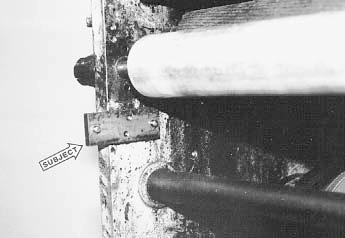
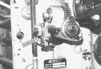
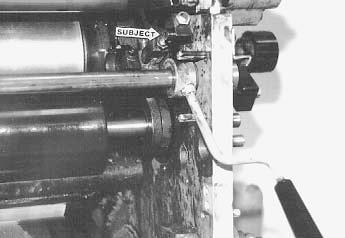
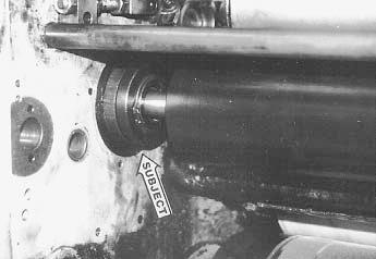
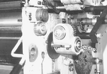
7 DISASSEMBLY 1 Remove the OPS and NOPS side covers. Remove the water form and ductor rollers. Remove water pan and bottle assembly. Remove the OPS and NOPS water pan mounting blocks (subject arrow NOPS shown). 2 At the NOPS, remove the pan roller drive sleeve (subject arrow) by loosening the set screw securing it to the pan roller. 3 At the OPS and NOPS, remove the pan roller bearing housing by removing the phillips head screws (subject arrows NOPS shown). 7

8 8
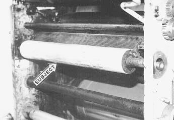
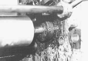
9 DISASSEMBLY 4 Remove the pan roller (subject arrow) from the press. 5 At the OPS, remove the drive arm, set collar and torsion spring from the end of the water ductor roller shaft (subject arrow). 6 At the OPS and NOPS loosen the ductor roller mounting brackets (right subject arrow, NOPS shown) and the set collar (left subject arrow). Thoroughly clean the ductor shaft and slide it out of the press. After shaft is out, tap out the bronze bushing at each side. 9
10 10
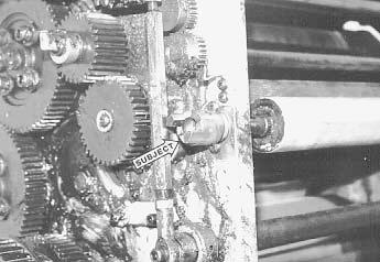
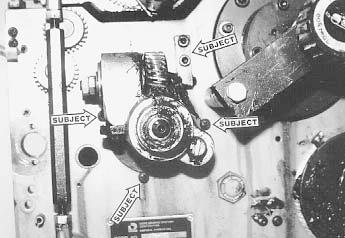
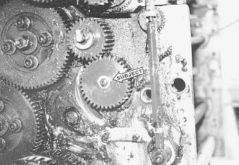
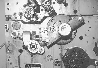
11 DISASSEMBLY 7 At the OPS, remove the phillips head screws (lower subject arrows) retaining the oscillator bearing housing. Remove the cap screws securing oscillator anchor block (upper subject arrow) and remove it from the press. 8 Remove the bolt on the end of the oscillator shaft that secures the oscillator drive mechanism to the oscillator. Remove the drive from the oscillator. It may be necessary to use a gear puller to remove the drive. Save the drive assembly for reassembly. 9 Using a 1/8" punch, remove the roll pin securing the worm (subject arrow) on the oscillator shaft. Remove the worm and ball bearing, saving ball bearing for reassembly. 11

12 12
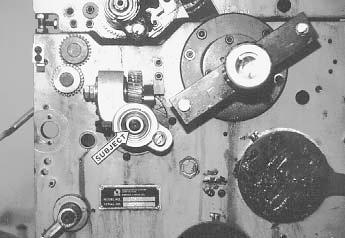
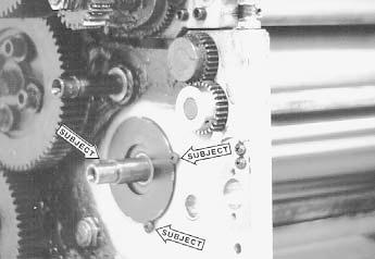
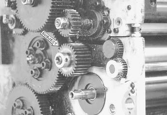
13 DISASSEMBLY 10 At the NOPS, remove the button head bolt (subject arrow) securing the oscillator drive gear to the oscillator. Remove the gear and the woodruff key and save for reassembly. 11 Remove the oil filler and set collar (subject arrow) securing the oscillator idler gear on the NOPS. Remove the gear and save for reassembly. 12 At the NOPS, remove the three phillips head screws (subject arrows) securing the oscillator bearing housing. 13
14 14
15 DISASSEMBLY 13 At the OPS and NOPS, remove the shoulder bolts (subject arrow OPS shown) from water form block and save for reassembly. 14 At the OPS and NOPS, remove the snap rings (subject arrow OPS shown) from the bearing housings. Remove the housings from the press and save for reassembly. 15 With the housings removed, the water form hangers and spacers can be removed. Save these parts for reassembly. Remove the oscillator from the press. This completes the disassembly process. Thoroughly clean all parts saved for reassembly and check all mating parts (i.e. vibrator housing to form hangers) for excessive wear. Replace if necessary. This is important for proper operation of the new Crestline Altra TM Series dampening system. Refer to your Didde parts guides for the correct part numbers. Also, clean the inside of the press frames around the dampener area. 15
16 16
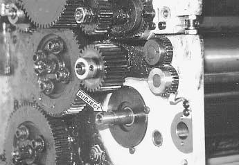
17 INSTALLATION 1 Replace the bushings in the oscillator housing with the new ones (06-134) provided. 2 Install the Crestline Altra TM Series oscillator roller ( ) in the same manner as the original. It is a good idea to leave the protective paper on the roller until the end of this step. Be sure to install the form roller hangers, spacers and snap rings (subject arrow) over the journals as they originally were before installing the bearing housings. Secure the housings to the press using the original phillips head screws. Leave the OPS side housing loose as it will need to be rotated later when installing the oscillation drive. Replacement bolts for each end of oscillator have been provided if needed. 3 Install the original oscillator idler gear (subject arrow) on the NOPS using the original thrust washer and set collar. Replace the oil filler (not shown in the photo) on the end of the shaft. 17
18 18
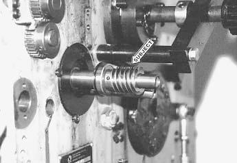
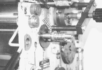
19 INSTALLATION 4 Install the supplied woodruff key (subject arrow) in the slot in the end of the NOPS oscillator journal. Install the oscillator drive gear using the new hardware. 5 At the OPS, first install the supplied new replacement bearing (#06-133, subject arrow) and then the new worm (# ) on the oscillator roller journal. The retaining ring on the bearing goes toward the press frame. Install the supplied roll pin through the worm to secure it to the journal. 6 Remove the two nuts securing the worm gear in the oscillation drive housing. Remove the worm gear and the 3 bearings and replace them with the new ones provided. You must use the new worm gear as it is different from the original. 19
20 20
21 INSTALLATION 7 Install the oscillation drive assembly on the oscillator journal. Make sure the bearing, installed in step 4, is seated in the housing before securing the drive assembly to the oscillator using the new hardware (subject arrow). 8 Replace the pin in the block with the new one provided. Install the block and arm assembly (subject arrow) by first inserting the arm on the pin in the worm gear. The set screw holding the pin in the block goes toward the press frame. Rotate the assembly until the holes in the block line up with the holes in the press frame. Loosely install the bolts securing the block to the press frame. When everything is properly aligned, the vibrator will be easy to turn by hand and you can tighten the bolts. Install the new water form roller into the original form housing. 9 At OPS and NOPS, install the dampener frames using the supplied flanged spools. At the OPS, you will need to tap the lower water form lever stop pin toward the outside of the press about 1/4" to allow for dampener frame clearance. Do not over-tap or the press cover will not close. Secure with the hex-head bolts and lock washers. 21
22 22
23 INSTALLATION 10 Insert the intermediate roller (the smaller of the two shafted rollers) into the slots in the frames and up against oscillator. The pin in the collar at the NOPS should be facing the open end of the slot. Loosen the set screw in all three collars on the roller shaft. Slide the shaft as far to the OPS as possible. Slide the pinned collar up against the NOPS frame and tighten. Next, center the roller relative to the water form roller and tighten the two remaining collars up against the roller to lock in place. To double check for correct position, jog the press while observing the stroke of the oscillator relative to both the water form and intermediate roller. Reposition the intermediate roller if necessary. 11 Install the metering roller similar to the intermediate roller in step 10. The pin in the NOPS collar, however, should be facing the closed end of the slot. Remove the end play in the shaft as in step 10 and center the metering roller to the intermediate roller. 12 Install the pan roller into the eccentric brackets. The shorter end will go to the OPS and the roller should be centered to the metering roller. Replace the bearing caps. Do not adjust the middle screw in the bearing cap, as this has been factory set for proper cap tension. 23
24 24
25 INSTALLATION 13 The water pan and shield attach as shown, however these should be left off until final roller settings are made. 14 Replace the original plastic safety cover with the new one provided. Transfer the original hardware to the new guard. YOU ARE NOW READY TO MAKE FINAL ADJUSTMENTS 25
26 26
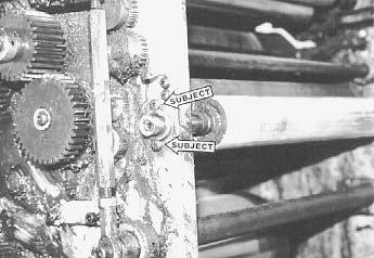
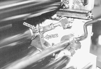
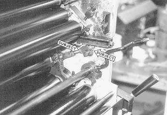
27 FINAL ADJUSTMENTS 1 OSCILLATOR TO FORM ROLLER PRESSURE Raise the water form control handle to the OFF position. Dab some ink on the water form roller and slowly run the press for seconds to distribute (only if the form and oscillator will ink up at this time). Turn the press off and wait for seconds before jogging the press forward enough to observe the stripe between the water form and oscillator roller. The correct stripe will be 5/32" (4mm) wide and parallel across the width of the roller. 5/32" (4mm) To adjust, insert the allen wrench supplied with the press into the allen nut (right subject arrow) on each form roller bracket. Lightly tap the allen wrench to unlock the eccentric bearing cups. With a 5/32" allen wrench inserted into the bearing cap screw (lower subject arrow) rotate the bearing cups as necessary to obtain the proper stripe. After obtaining the correct stripe, retighten the allen nuts. Recheck the stripe and repeat the adjustment if necessary. 5/32" (4mm) 2 FORM ROLLER TO PLATE CYLINDER PRESSURE With a properly packed plate mounted on the plate cylinder, lower the water form control handle to the ON position. After a few seconds, raise the handle to the OFF position. Jog the press slightly backwards and observe the stripe on the plate. The correct stripe will be 5/32" (4mm) wide and parallel across the width of the plate. To adjust, loosen or tighten the lock nuts (subject arrows) on each side of the link blocks. When the correct stripe is obtained, ensure both lock nuts are tight. Recheck the stripe and repeat the adjustment if necessary. 27
28 28
29 FINAL ADJUSTMENTS 3 5/32" (4mm) INTERMEDIATE TO METERING ROLLER PRESSURE This pressure is adjusted by loosening the lock nut in the center of the cap (#2) and turning the set screw (#1). Turning the screw in will increase the stripe and vice-versa. Jog the press and observe the stripe between these two rollers. It should be 5/32" (4mm). Setting this stripe automatically sets the intermediate to oscillator pressure. 4 PAN ROLLER TO METERING ROLLER PRESSURE This pressure is adjusted by loosening the set screw (#3) and rotating the pan roller eccentric brackets. Rotating the brackets toward the metering roller increases the stripe and vice-versa. This stripe should be 5/32" (4mm). Jog the press to check. 5/32 (4mm) 5 WATER LEVEL IN PAN Attach the circulator filler pipe to the water pan and connect the feed line and valve. Connect the drain hose to the large pipe at the bottom of the pan. Insert the weir into the drain hole at the bottom of the pan. Shut off the feed valve completely and turn on the circulator pump. Slowly open the feed valve until fountain solution slowly flows from the end of the pipe. The weir will automatically control the water level inside the pan. Beware of adjusting the water feed too high as this will overflow the pan. YOU ARE NOW READY TO PRINT 29
30 BASIC OPERATION START OF DAY A. Make sure all rollers are in place. B. Attach splash shield to the dampener. C. Mount plate to cylinder. Wipe down all plates before running. Pre-ink the Crestline Altra TM Series dampener before running the plates with an extremely light coverage of ink. D. Adjust circulator flow to water pans. NOTE: Accel recommends using the proper fountain solution for the plate material being run on the press. A good acid/gum etch should be used with metal plates. RUNNING DURING THE DAY A. In general, the Crestline Altra TM Series Dampener should not have to be adjusted from job to job. The form roller setting should never be changed unless it has deviated from the factory specification of 5/32" to the plate. B. Adjustment of the amount of water fed to the plate is made by altering the pan roller to metering roller pressure. Less pressure equals more water. C. In general, more water will only be required when going from a metal plate to an electrostatic or silvermaster type plate. 30
31 CLEANING & MAINTENANCE WASH UPS DURING THE DAY 1. Shut off circulator and drain the excess water from the pan. 2. Mount cleanup mat to the press or if applicable, a wash-up attachment along with a metal plate to act as a bridge between dampener and inker. 3. Turn on the press and squirt a small amount of press wash on the ink and dampener rollers. (Squirt ink rollers only if using a wash-up attachment.) 4. Drop both the dampener and ink forms to the plate. If using an attachment, generally the dampener will pick up enough roller wash off the plate to clean itself, so apply wash directly to the dampener only when necessary. 5. Remove water pan and clean any solution left in it. 6. Be sure to wipe excess clean up solution from the ends of the dampener metering and pan rollers. END OF THE DAY Wash up dampener as described above. Pay close attention to cleaning the ends of the pan and metering rollers that extend past the form rollers. 31
32 CLEANING & MAINTENANCE DEGLAZING THE DAMPENER Periodic deglazing of water-soluble contaminants will be necessary with the Crestline Altra TM Series. Typically, once every 2-3 weeks will be sufficient, unless you are running electrostatic plates on a daily basis whereas deglazing should be performed weekly. A 50/50 solution of household ammonia and hot water can be used for deglazing purposes. If you prefer a commercially available deglazer, avoid those containing pumice or gritty substances. Accel offers a product called COMPOUND X which is what we recommend for deglazing our system. Contact your dealer or Accel for more information. Always follow deglazing with straight water and then roller wash. OILING AND GREASING THE DAMPENER A. Place a small amount of grease on the gears once a month. B. Inject grease into the oscillator worm drive once a month. 32
33 CLEANING & MAINTENANCE CRESTLINE ALTRA TM SERIES CLEANING & MAINTENANCE CHART Daily Weekly Bi-Weekly Monthly Wash Rollers Deglaze Rollers Metal Plate Users Silvermaster Plate Users Electrostatic Plate Users Grease Gears Inspect Ball Bearings Check Roller Pressures Check Roller Surfaces 33
34 34
35 35
36 36
37 37
38 38
39 39
40 40
41 41
42 42
43
44 11103 Indian Trail, Dallas, TX Phone , Fax Web Site
Crestline Dampening System. Installation Instructions. Hamada RS34 & VS34 Satellite Unit. For Presses Originally Equipped With. Integrated Dampeners
 Crestline Dampening System Installation Instructions Hamada RS34 & VS34 Satellite Unit For Presses Originally Equipped With Integrated Dampeners X88-113 01/2001 Rev-A GENERAL INFORMATION ATTENTION CRESTLINE
Altra Series Dampener
 Crestline TM Altra Series Dampener Installation Instructions Ryobi 512 X88-69 10/98 Rev-A GENERAL INFORMATION ATTENTION CRESTLINE ALTRA SERIES TM DAMPENER OWNER! Accel Graphic Systems provides parts and
Crestline Dampening System. Installation Instructions. A.B. Dick 350, 360, 375 Single & Dual Lever Machines. X /01 Rev-A
 Crestline Dampening System Installation Instructions A.B. Dick 350, 360, 375 Single & Dual Lever Machines X88-20 01/01 Rev-A GENERAL INFORMATION ATTENTION CRESTLINE DAMPENER OWNER! Accel Graphic Systems
Crestline Dampening System
 Crestline Dampening System Installation Instructions Ryobi 3200 MCD Itek 985 X88-31 Rev-A 5/98 GENERAL INFORMATION ATTENTION CRESTLINE DAMPENER OWNER! Accel Graphic Systems provides parts and service through
Crestline Dampening System Installation Instructions
 Crestline Dampening System Installation Instructions Hamada RS/ VS 34 II Parent Unit DU 34 II Upper Unit X88-104 Rev-B 01/2001 GENERAL INFORMATION ATTENTION CRESTLINE DAMPENER OWNER! Accel Graphic Systems
CRESTLINE DAMPENING SYSTEM INSTALLATION INSTRUCTIONS. Ryobi 3302M Itek 3985 A.B. Dick 9985 X /99
 CRESTLINE DAMPENING SYSTEM INSTALLATION INSTRUCTIONS Ryobi 3302M Itek 3985 A.B. Dick 9985 X88-32 3/99 GENERAL INFORMATION ATTENTION CRESTLINE DAMPENER OWNER Accel Graphic Systems provides parts and service
Crestline Dampening System. Installation Instructions. Ryobi 500N X /98
 Crestline Dampening System Installation Instructions Ryobi 500N X88-33 7/98 GENERAL INFORMATION ATTENTION CRESTLINE DAMPENER OWNER! Accel Graphic Systems provides parts and service through its authorized
Crestline Altra Series TM Dampener. Installation Instructions. Heidelberg GTO. X /98 Rev-A
 Crestline Altra Series TM Dampener Installation Instructions Heidelberg GTO X88-63 7/98 Rev-A GENERAL INFORMATION ATTENTION CRESTLINE ALTRA SERIES TM DAMPENER OWNER! Accel Graphic Systems provides parts
PowderPro Spray System
 PowderPro Spray System Installation Instructions Hamada C248 X88-72 10/98 REV-C 2657 GENERAL INFORMATION ATTENTION POWDERPRO OWNER! Accel Graphic Systems provides parts and service through its authorized
Roller Removal Instructions
 Roller Removal Instructions Rollers for the Crestline dampener are broken down into numerical categories as follows: Prefix Roller Position Prefix Roller Position x07-01.. Form Roller x07-04.. Oscillator
HYDRAULICS. TX420 & & lower. Hydraulic Tandem Pump Removal. 4. Remove the LH side panel (Fig. 0388).
.") TX420 & 425 240000299 & lower 4. Remove the LH side panel (Fig. 0388). Hydraulic Tandem Pump Removal Note: Cleanliness is a key factor in a successful repair of any hydraulic system. Thoroughly clean all
TX420 & 425 240000299 & lower 4. Remove the LH side panel (Fig. 0388). Hydraulic Tandem Pump Removal Note: Cleanliness is a key factor in a successful repair of any hydraulic system. Thoroughly clean all
'99-03 CHEVROLET/GMC IFS 4WD 6" SUSPENSION SYSTEM P/N INSTALLATION INSTRUCTIONS
 1/16/04 '99-03 CHEVROLET/GMC IFS 4WD 6" SUSPENSION SYSTEM P/N. 10-41099 INSTALLATION INSTRUCTIONS NOTE: Each Lift Kit and options to Lift Kits are packaged separately. Therefore, installation procedures
CALIFORNIA TRIMMER MOWER MAINTENANCE MANUAL
 CALIFORNIA TRIMMER MOWER MAINTENANCE MANUAL 2 Table of Contents Section 1: General Information Page Handle Assembly Instructions 4 Maintenance All Models 6 Oil Change Procedures All Models 9 Height Adjustment
160S Rewind Option Kit Installation Instructions
 Installation Instructions GENERAL This kit includes the parts and documentation necessary to install the Media Rewind Option into the Zebra 160S printer. Read these instructions thoroughly before attempting
WARNING: ALWAYS relieve fuel pressure before disconnecting any fuel related component. DO NOT allow fuel to contact engine or electrical components.
 4.0L V8 - VINS [K,U] Selected Block 1990 Lexus LS 400 For Lextreme Powertrain 2020 S. Hacienda Blvd. # D Hacienda Heights California 91745 Copyright 1998 Mitchell Repair Information Company, LLC Friday,
1984 Dodge W250 PICKUP
 1984 Dodge W250 PICKUP Submodel: Engine Type: V8 Liters: 5.2 Fuel Delivery: CARB Fuel: GAS Dana 44 MODELS THROUGH 1984 2. Raise and safely support the vehicle, then remove the wheel hub and bearings as
1988 Chevrolet Pickup V SUSPENSION - FRONT (4WD)' 'Front Suspension - "V" Series 1988 SUSPENSION - FRONT (4WD) Front Suspension - "V" Series
' 'Front Suspension - V Series 1988 SUSPENSION - FRONT (4WD) Front Suspension - V Series") 1988 SUSPENSION - FRONT (4WD) Front Suspension - "V" Series DESCRIPTION NOTE: Vehicle serial numbers used in this article has been abbreviated for common reference to Chevrolet and GMC models. Chevrolet
1988 SUSPENSION - FRONT (4WD) Front Suspension - "V" Series DESCRIPTION NOTE: Vehicle serial numbers used in this article has been abbreviated for common reference to Chevrolet and GMC models. Chevrolet
Rear Roller Brush Kit Greensmaster 3150 & 3250
 Rear Roller Brush Kit Greensmaster 50 & 50 Model No. 04640 Model No. 0464 Form No. 8 808 Rev. B Installation Instructions Note: The Rear Roller Brush Kit can only be installed on cutting unit models 0460
UOW Series Repair Manual UOW-11 & UOW-T60 Series
 UOW Series Repair Manual UOW-11 & UOW-T60 Series 100000 SE Pine St., Portland, OR 97216 800-852-1368 503-254-6600 www.aimco-global.com Contents Page 1. Tools Needed for Repair 2 2. Disassembly and Reassembly
Maintenance Information
 16573321 Edition 3 February 2014 Air Grinder Series 61H Maintenance Information Save These Instructions Product Safety Information WARNING Failure to observe the following warnings, and to avoid these
Discount-Equipment.com
 REQUIRED TOOLS LS Series Remix Shaft Installation Instructions /8", /6", /2" Allen Wrenches Snap Ring Pliers (Light Duty) /" Combination Wrench Loctite #22 Blue /" Socket w/ /8" Ratchet Electric Drill
Mandatory X Information Recommended Change. Series/Parts Affected: LS40D, LS40TD, LS50TD and LS60TD Concrete Pumps
 Service Bulletin No. CP20060428 Subject: Remix Shaft Coupler Retrofit Kit Model: LS40D, LS40TD, LS50TD & LS60TD Product Group: Concrete Pump Date: April 28, 2006 SERVICE BULLETIN Group: CP Mandatory X
REPAIR MANUAL URW SERIES. URW-6, 8, 9, 10 & 12 Series Repair Manual
 REPAIR MANUAL URW SERIES URW-6, 8, 9, 10 & 12 Series Repair Manual Contents Page 1. Tools Needed for Repair 1 2. Disassembly and Reassembly of the Cam Casing 2-4 3. Disassembly and Reassembly of the Gear
TCI Turbo 400 Full Manual Valve Body. Shift Pattern: Park Reverse Neutral First Second Third. NOTE: You must reuse stock manual control valve.
 TCI 221100 Turbo 400 Full Manual Valve Body Shift Pattern: Park Reverse Neutral First Second Third This Kit Contains: (1) Turbo 400 Full Manual Valve Body (1) Separator Plate & Gaskets (1) Pressure Regulator
INSTALLATION & OWNER S MANUAL
 Rev. E p. of 3 INSTALLATION & OWNER S MANUAL V446 Front Cab Kit and V446 Rear Cab Kit for RTV 40 INSTALLATION & OWNER S MANUAL The contents of this envelope are the property of the owner. Be sure to leave
97-06 Jeep TJ Wrangler 2. 5 " & 4 " S u s p e n s i o n L i f t Installation Instructions
 97-06 Jeep TJ Wrangler 2. 5 " & 4 " S u s p e n s i o n L i f t Installation Instructions Safety Glasses Metric / Standard Wrenches & Sockets Drill / Assorted Drill Bits Floor Jack Jack Stands Measuring
2.2L 4-CYL - VIN [S]
![2.2L 4-CYL - VIN [S]](/thumbs/72/67564355.jpg "2.2L 4-CYL - VIN [S]") 2.2L 4-CYL - VIN [S] 1994 Toyota Celica 1994 ENGINES Toyota 2.2L 4-Cylinder Celica NOTE: For repair procedures not covered in this article, see ENGINE OVERHAUL PROCEDURES - GENERAL INFORMATION article
2.2L 4-CYL - VIN [S] 1994 Toyota Celica 1994 ENGINES Toyota 2.2L 4-Cylinder Celica NOTE: For repair procedures not covered in this article, see ENGINE OVERHAUL PROCEDURES - GENERAL INFORMATION article
Maintenance Information
 16573370 Edition 2 February 2014 Air Grinder 99V Series Maintenance Information Save These Instructions Product Safety Information WARNING Failure to observe the following warnings, and to avoid these
Maintenance Information
 Form 16573321 Edition 1 July 2004 Air Grinder Series 61H Maintenance Information Save These Instructions Always wear eye protection when operating or performing maintenance on this tool. Always turn off
Hudson-Essex. Service Manual Supplement. Hudson Cars 750,001 up
 1 9 2 6 Hudson-Essex Service Manual 1927 Supplement Hudson Cars 750,001 up Hudson Rear Axle (Cars numbered 750,001 and upward) Brakes (Cars numbered 750,001 and upward) See page 18 Transmission Group
Valtek Auxiliary Handwheels and Limit Stops
 Valtek Auxiliary s and Limit Stops Table of Contents Page 1 General information 2 Installation 2 Side-mounted handwheels, size 25 and 50 (linear actuators) 3 Side-mounted handwheels, size 100 and 200 (linear
LS Series. Remix Shaft Installation Instructions REQUIRED TOOLS PARTS WORK SAFELY! PREPARATION/SAFETY PROCEDURES
 REQUIRED TOOLS LS Series Remix Shaft Installation Instructions /8", /6", /2" Allen Wrenches Snap Ring Pliers (Light Duty) /" Combination Wrench Loctite #22 Blue /" Socket w/ /8" Ratchet Electric Drill
CHAINGUARD REGAL ST COLOR
 DESOTO/ REGAL HAULER PARTS LIST Item Part # Description QTY Item Part # Description QTY 1 11871 REFLECTOR KIT TRIKE 1 32 11764 FENDER BRACE 24" MWT 1 2 12199 SCREW #14 x 3/4 4 33 12176 NUT5/16-24 HEX 2
UAN Series Pneumatic Nutrunner Repair Manual
 UAN Series Pneumatic Nutrunner Repair Manual PO Box 16460, Portland, OR 97292-0460 503-254-6600 Fax 503-255-2615 www.aimco-global.com Contents Page 1. Tools Needed for Repair of UAN Series Pneumatic Nutrunner
'88-'00 CHEVROLET/GMC IFS 4WD(8LUG) OLD BODY STYLE 6" SUSPENSION SYSTEM P/N
 OLD BODY STYLE 6 SUSPENSION SYSTEM P/N") 4/10/13 '88-'00 CHEVROLET/GMC IFS 4WD(8LUG) OLD BODY STYLE 6" SUSPENSION SYSTEM P/N. 10-41888 INSTALLATION INSTRUCTIONS APPLICATION WARNING: Applicable for hub mounted ABS sensor models only. Not for 1992-94
4/10/13 '88-'00 CHEVROLET/GMC IFS 4WD(8LUG) OLD BODY STYLE 6" SUSPENSION SYSTEM P/N. 10-41888 INSTALLATION INSTRUCTIONS APPLICATION WARNING: Applicable for hub mounted ABS sensor models only. Not for 1992-94
C15C C15C. Page 1 of 20
 2 x Lid Front Hinge 1135 8 x M8 Bolt 8 x M8 Washer (3mm Thick) 4 x M6 Large washers 4 x M6 Spring washers 4 x M6 x 40mm Bolts 6 x M6 20mm Bolts 6 x M6 Washers 20 x Screws 2 x Lid mount gas strut bracket
Operation and Maintenance Instructions
 Operation and Maintenance Instructions One Research Drive Stratford, CT 06615 (203) 375-0063 www.sonicmixing.com 1 Installation and Start-up Do not perform following adjustments without disconnecting power
INSTALLATION INSTRUCTION 88051
 INSTALLATION INSTRUCTION 88051 For Rancho Suspension System RS6551: Chevrolet 2500 Suburban & 2500 Avalanche READ ALL INSTRUCTIONS THOROUGHLY FROM START TO FINISH BEFORE BEGINNING INSTALLATION Rev C IMPORTANT
DRIVE AXLE Volvo 960 DESCRIPTION & OPERATION AXLE IDENTIFICATION DRIVE AXLES Volvo Differentials & Axle Shafts
 DRIVE AXLE 1994 Volvo 960 1994 DRIVE AXLES Volvo Differentials & Axle Shafts 960 DESCRIPTION & OPERATION All 960 station wagon models use type 1041 rear axle assembly. All 960 4-door models use type 1045
JARVIS. Model Buster V (CE) Beef Splitting Band Saw
 Beef Splitting Band Saw") Model Buster V (CE) Beef Splitting Band Saw EQUIPMENT SELECTION............. Ordering No. TABLE OF CONTENTS......................... Page Buster V Band Saw Shower Head.......... 4006049 Shower Head and
Model Buster V (CE) Beef Splitting Band Saw EQUIPMENT SELECTION............. Ordering No. TABLE OF CONTENTS......................... Page Buster V Band Saw Shower Head.......... 4006049 Shower Head and
CHAINGUARD REGAL ST COLOR
 DESOTO/ REGAL HAULER PARTS LIST Item Part # Description QTY Item Part # Description QTY 1 11871 REFLECTOR KIT TRIKE 1 32 11762 FENDER BRACE 20" MWT 1 2 12199 SCREW #14 x 3/4 4 11764 FENDER BRACE 24" MWT
Maintenance Information
 16575243 Edition 2 October 2013 Air Screwdrivers 1R Series Maintenance Information Save These Instructions Product Safety Information WARNING Failure to observe the following warnings, and to avoid these
DYNATRAC THE PERFORMANCE AXLE SPECIALIST
 DYNATRAC THE PERFORMANCE AXLE SPECIALIST DynaLoc Installation Instructions, Appendix A iinformation: Dynatrac has included an additional bushing in the DynLoc kit. Part DA60-0022-L will be referred to
Read these instructions thoroughly before attempting to install this option.
 Rewind Option Kit Installation Instructions This kit includes the parts and documentation necessary to install the Media Rewind option into the following printers: 0XiIIIPlus, 0 dpi 0XiIIIPlus, 00 dpi
Amarillo PUMP DRIVES (250 HP THROUGH 350 HP) INSTRUCTIONS FOR REPAIRING MODELS 250, 300, and 350
 INSTRUCTIONS FOR REPAIRING MODELS 250, 300, and 350") Amarillo PUMP DRIVES (250 HP THROUGH 350 HP) INSTRUCTIONS FOR REPAIRING MODELS 250, 300, and 350 Amarillo Right Angle Pump Drives, if properly installed and maintained, should provide years of service
Amarillo PUMP DRIVES (250 HP THROUGH 350 HP) INSTRUCTIONS FOR REPAIRING MODELS 250, 300, and 350 Amarillo Right Angle Pump Drives, if properly installed and maintained, should provide years of service
STERNDRIVE UNIT 3 A DRIVE SHAFT HOUSING
 STERNDRIVE UNIT 3 A 23262 DRIVE SHAFT HOUSING Table of Contents Page Specifications............................ 3A-1 Torque Specifications.................. 3A-1 Upper Drive Shaft Bearing Preload.......
Model QED-D, QED-A, QED-L
 This supplement is for Field Service use only, as complete dis-assembly and re-assembly of the QED reducer by the customer is NOT recommended. This supplement only extends to single reduction QED units.
97-06 Jeep TJ Wrangler Installation Instructions Models Kit# TJ251K/TJ401K-SX -DX 03 Models Kit# TJ253K/TJ403K-SX -DX
 97-06 Jeep TJ Wrangler Installation Instructions 97-02 Models Kit# TJ251K/TJ401K-SX -DX 03 Models Kit# TJ253K/TJ403K-SX -DX Before beginning the installation, read these instructions and the enclosed driver
Sachs shock manual. ( ) 2 & 4 Stroke RR Enduro. ( ) RS Dual Sport
 2 & 4 Stroke RR Enduro. ( ) RS Dual Sport") Sachs shock manual (2013 2015) 2 & 4 Stroke RR Enduro (2014-2015) RS Dual Sport 1 Introduction The procedures in this manual must take place in a clean environment using professional tools and some specific,
Sachs shock manual (2013 2015) 2 & 4 Stroke RR Enduro (2014-2015) RS Dual Sport 1 Introduction The procedures in this manual must take place in a clean environment using professional tools and some specific,
E-LIFT II+ SYSTEM WITH SPRING LEVER FOR A-SERIES AND FULL FRAME LOOMS
 Congratulations on your purchase of the E-Lift II+ system. This system replaces the action of treadling, eliminating leg strain and fatigue. When you activate the Foot Switch, the motor turns, and selected
LoMax 205 CASE & 3:1 GEAR SET. Manufactured by JB CONVERSIONS, INC. Phone: Installation Instructions for the GM NP205 Transfer Case
 LoMax 205 CASE & 3:1 GEAR SET Part No. 2800 Instruction Rev: 2007.08.16 Manufactured by JB CONVERSIONS, INC. Phone: Installation Instructions for the GM NP205 Transfer Case Kit Components: 1. (1) 42x25
INSTALLATION INSTRUCTION 88148
 INSTALLATION INSTRUCTION 88148 Rev C For Rancho Suspension Systems RS6548, RS6549 & RS6550: GM 2500HD, 2500, and 1500HD Trucks READ ALL INSTRUCTIONS THOROUGHLY FROM START TO FINISH BEFORE BEGINNING INSTALLATION
INSTALLATION AND OPERATING INSTRUCTIONS
 ASTRO ENVELOPE FEEDER AMC-2000-5 FOR RYOBI 3302 / ITEK 3985 (2 COLOR) INSTALLATION AND OPERATING INSTRUCTIONS INTRODUCTION Thank you for purchasing the Astro Envelope Feeder. It is fast, efficient, reliable,
DYNATRAC PRODUCTS V5.3
 DYNATRAC PRODUCTS V5.3 2000-2008 Dodge Hub Kit Stage 1 4x4, Front Axle Free Spin Conversion Kit Note: This Kit is not Approved for 2007 & up 3500 Cab and Chassis Trucks Due to a Larger U-Joint (If U-Joint
Fig Variable Speed Valve Parts
 5 DISASSEMBLY OF VARIABLE SPEED CONTROL VALVE (Seal Replacement with Control Valve in the Bobcat). Remove seat and seat plate (Fig. ).. Remove variable speed control lever linkage rod. 3. Remove temperature
Tooling Assistance Center
 Safeguards are designed into this application equipment to protect operators and maintenance personnel from most hazards during equipment operation. However, certain safety precautions must be taken by
Transmission Overhaul Procedures-Bench Service
 How to Assemble the Lower Reverse Idler Gear Assembly Special Instructions In 1996 Eaton changed the reverse idler system design. In the nut design, the reverse idler bearing was lubricated through a hole
Disassembly Instructions hp. Dynafile II Models: 40352, 40353
 Disassembly Instructions - 0.4 hp. Dynafile II Models: 40352, 40353 Important: Use these instructions along with the tool parts page or manual. Notice: Shut off the air supply and depress throttle lever
Brake System H TX, H2.0TXS [B475]; H TX [B466] Safety Precautions Maintenance and Repair
![Brake System H TX, H2.0TXS [B475]; H TX [B466] Safety Precautions Maintenance and Repair](/thumbs/86/93834005.jpg "Brake System H TX, H2.0TXS [B475]; H TX [B466] Safety Precautions Maintenance and Repair") HMM180001 Brake System H1.5-1.8TX, H2.0TXS [B475]; H2.5-3.5TX [B466] Safety Precautions Maintenance and Repair When lifting parts or assemblies, make sure all slings, chains, or cables are correctly fastened,
HMM180001 Brake System H1.5-1.8TX, H2.0TXS [B475]; H2.5-3.5TX [B466] Safety Precautions Maintenance and Repair When lifting parts or assemblies, make sure all slings, chains, or cables are correctly fastened,
9905/9910/9910D/ 9910XCS/9910XC2 Service Reference Manual
 9905/9910/9910D/ 9910XCS/9910XC2 Service Reference Manual 1996, A.B.Dick Company P/N 177187 (REV. 0) WARNING: This equipment must be connected to a properly grounded three (3) wire outlet. Failure to do
Maintenance Information
 45528270 Edition 1 June 2007 Barring Motor T480 Series Maintenance Information Save These Instructions WARNING Always wear eye protection when operating or performing maintenance on this Barring Motor.
TABLE OF CONTENTS DESCRIPTION. Safety Instructions & Safety Sign Locations Operating Instructions Assembly Instructions...
 TABLE OF CONTENTS DESCRIPTION PAGE Warranty... 1 Safety Instructions & Safety Sign Locations... 2 Operating Instructions... 3 Assembly Instructions... 5 500 & 600 Snowblower Drawings... 8 500 & 600 Snowblower
DL650 Odyssey Luggage Installation Guide
 DL650 Odyssey Luggage Installation Guide Thank you for purchasing Jesse Luggage for your Motorcycle. Our Luggage, handcrafted in the USA, is designed for those with an interest in finding the most durable
DESCRIPTION Acura TSX SUSPENSION Front - TSX. NOTE: For system description and component location, see Fig. 1.
 2004 SUSPENSION Front - TSX DESCRIPTION NOTE: For system description and component location, see Fig. 1. Fig. 1: Identifying Front Suspension Components Wednesday, March 12, 2008 8:30:45 8:30:55 PM Page
Operating Instruction
 Operating Instruction Drive element LEWA - ecosmart type LCA with manual stroke adjustment, motor mounted vertically Table of contents 1 General information / safety 1.1 Important preliminary information
Slave Cylinder Weep Hole Drilling Procedure
 Slave Cylinder Weep Hole Drilling Procedure Tools Required: T20 Torx Driver T25 Torx Driver T25 Torx Bit with ¼ Ratchet Wrench 4mm Hex Key (Allen wrench) 5mm Hex Key 6mm Hex Key 8mm Hex Key 12mm Hex Key
Discount-Equipment.com
 LS40D, LS40TD, LS50TD, LS60TD LS-Series Remix Shaft Coupler Retrofit Kit Installation Instructions The following instructions are intended to assist the user in the installtion of the LS-Series Remix Shaft
Instruction Sheet Kit Number:
 Instruction Sheet Kit Number: 72101800 TRACK CONVERSION KIT For All Wheel-Drive 921000 Models WARNING: FAILURE TO FOLLOW INSTRUCTIONS could result in personal injury and/or damage to unit. Read, understand,
1.6L 4-CYL - VIN [E]
![1.6L 4-CYL - VIN [E]](/thumbs/81/84172348.jpg "1.6L 4-CYL - VIN [E]") 1.6L 4-CYL - VIN [E] 1993 Nissan Sentra 1993 NISSAN ENGINES 1.6L 4-Cylinder NX, Sentra * PLEASE READ THIS FIRST * NOTE: For engine repair procedures not covered in this article, see ENGINE OVERHAUL PROCEDURES
1.6L 4-CYL - VIN [E] 1993 Nissan Sentra 1993 NISSAN ENGINES 1.6L 4-Cylinder NX, Sentra * PLEASE READ THIS FIRST * NOTE: For engine repair procedures not covered in this article, see ENGINE OVERHAUL PROCEDURES
Maintenance Instructions
 General Note These instructions contain information common to more than one model of Bevel Gear Drive. To simplify reading, similar models have been grouped as follows: GROUP 1 Models 11, 0, 1,, (illustrated),,
Housing (Front) - Remove
 - Remove") SENR9978-01 63 1. Lift the assembly (3) of the idler gear and the hub over the housing for the crankshaft front seal (2) and insert the hub into the recess in the cylinder block. Refer to illustration
SENR9978-01 63 1. Lift the assembly (3) of the idler gear and the hub over the housing for the crankshaft front seal (2) and insert the hub into the recess in the cylinder block. Refer to illustration
MASTER CYLINDER INSPECTION
 7-16 CHASSIS A-PDF Split DEMO : Purchase from www.a-pdf.com to remove the watermark Remove the piston assembly. MASTER CYLINDER INSPECTION MASTER CYLINDER Inspect the master cylinder bore for any scratches
97-06 Jeep Wrangler TJ Installation Instructions Kit #: TJ251K-SVX / TJ253K-SVX TJ401K-SVX / TJ403K-SVX
 www.skyjacker.com 97-06 Jeep Wrangler TJ Installation Instructions Kit #: TJ251K-SVX / TJ253K-SVX TJ401K-SVX / TJ403K-SVX Before beginning the installation, read these instructions and the enclosed driver
Safety First. Please remember to always use SAFE shop practices when performing all service procedures.
 Safety First Please remember to always use SAFE shop practices when performing all service procedures. 2006 Update Manual January 2006 Country Clipper 2006 Update Manual Index Joystick Kill Switch Oil
REPAIR MANUAL. Version 02/11/01 CD ZF GETRIEBE GMBH SAARBRÜCKEN
 REPAIR MANUAL 6 HP-26 Version CD ZF GETRIEBE GMBH SAARBRÜCKEN subject to alterations Copyright 2002 all rights reserved and published by ZF Getriebe GmbH, Saarbrücken, Department MKTD No part of this manual
AmTryke Adult Recumbent Model JT2000 #50-FC-2000
 AmTryke Adult Recumbent Model JT2000 #50-FC-2000 TOOLS Needed for Assembly 5 mm Allen Wrench 8 mm Socket or Wrench 10 mm Socket or Wrench 14 mm Socket or Wrench 15 mm Socket or Wrench 22 mm Socket or Adjustable
3.2 DRIVE TORQUE HUB. Roll, Leak and Brake Testing SECTION 3 - CHASSIS & TURNTABLE. 3-2 JLG Lift
 3.2 DRIVE TORQUE HUB Roll, Leak and Brake Testing 10 LUG PATTERN Torque-Hub units should always be roll and leak tested before disassembly and after assembly to make sure that the unit's gears, bearings
AmTryke Adult Recumbent Model HP1000 #50-HC-1000
 AmTryke Adult Recumbent Model HP1000 #50-HC-1000 TOOLS Needed for Assembly 5 mm Allen Wrench 8 mm Socket or Wrench 10 mm Socket or Wrench 14 mm Socket or Wrench 15 mm Socket or Wrench 22 mm Socket or Adjustable
REMOVAL & INSTALLATION
 REMOVAL & INSTALLATION Removal 1. Center steering wheel. Disconnect negative battery cable. Remove steering coupling shield (if equipped). Disconnect steering shaft at flexible coupling or pot joint. Note
phone
 AS-25-59 Ball AS-035508 Pinion Housing AS-035512 AS-036552 Ink Fountain Adjusting Screw AS-053111 Cam Follower sliding block fountain AS-085015 AS-087459 Idler Gear AS-1001705 Set Screw AS-1023953 Top
WRANGLER TJ INSTALLATION INSTRUCTIONS
 WRANGLER TJ INSTALLATION INSTRUCTIONS 1997-02 Models Kit# TJ251K/TJ401K 2003-06 Models Kit# TJ253K/TJ403K Before beginning the installation, read these instructions and the enclosed driver s WARNING NOTICE
rings used in the TuckAway Electric Monitor (#3352)
") STYLE 3352 O-Ring Ring Replacement Guide The following tools & materials are required for disassembly & servicing of the O-rings rings used in the (#3352) 5/64 Allen wrench 7/64 Allen wrench* 3/16 Allen
STYLE 3352 O-Ring Ring Replacement Guide The following tools & materials are required for disassembly & servicing of the O-rings rings used in the (#3352) 5/64 Allen wrench 7/64 Allen wrench* 3/16 Allen
Service Manual. #19 Gearmatic Winch
 Allis Chalmers Service Manual #19 Gearmatic Winch Service Manual THIS IS A MANUAL PRODUCED BY JENSALES INC. WITHOUT THE AUTHORIZATION OF ALLIS CHALMERS OR IT S SUCCESSORS. ALLIS CHALMERS AND IT S SUCCESSORS
Disassembly Instructions hp. Mini-Dynafile II
 Disassembly Instructions - 0.4 hp. Mini-Dynafile II Important: Use these instructions along with the tool parts page or manual. Notice: Shut off the air supply and depress throttle lever to deplete the
Bag 1. Bag 1. Center Pivot. Center Pivot
 8 00734 01901 5 Center Pivot Bag 1 3374 - Center Pivot Socket 4019 - Alum Pivot ball 3254-2-56 Button Head *Note - Sometimes it is helpful to slightly over-tighten the top clamp screws, then work the ball
OPERATION & MAINTENANCE INSTRUCTIONS MODEL: TC-300
 1-800-223-4540 ** 602-437-5020 OPERATION & MAINTENANCE INSTRUCTIONS MODEL: TC-300 READ INSTRUCTIONS THOROUGHLY BEFORE OPERATING MACHINE Contents Safety Instructions Pg 3 Operating Instructions Pg 4-5 (Light
WRANGLER TJ INSTALLATION INSTRUCTIONS Kit #: TJ251K/KN/KST/KSTN TJ401K/KN/KST/KSTN
 WRANGLER TJ INSTALLATION INSTRUCTIONS Kit #: TJ251K/KN/KST/KSTN TJ401K/KN/KST/KSTN Before beginning the installation, read these instructions and the enclosed driver s WARNING NOTICE thoroughly and completely.
Gelcoat Fluid Section
 3102-00-01 Fluid Section MAGNUM VENUS PRODUCTS Maintenance & Repair Manual Part No. M3102-00-01 Revision 05.30.01 Maintenance & Repair Manual Fluid Section Module MVP Venus Phone: (253) 854-2660 (800)
WARRANTY REGISTRATION AND POLICY
 WARRANTY REGISTRATION AND POLICY Buhler Manufacturing products are warranted for a period of twelve (12) months from original date of purchase, by original purchaser, to be free from defects in material
INSTALLATION & OWNER S MANUAL
 Rev. R p. 1 of 16 INSTALLATION & OWNER S MANUAL V4211 HARD SIDED CAB KIT and/or V4275 CAMO HARD SIDED CAB KIT INSTALLATION & OWNER S MANUAL The contents of this envelope are the property of the owner.
SECTION 5B MANUAL TRANSMISSION TABLE OF CONTENTS
 SECTION 5B MANUAL TRANSMISSION TABLE OF CONTENTS General Description and Operation... 5B-2 Shift Lever... 5B-2 Transmission Assembly... 5B-2 Specifications... 5B-3 Diagnostic Information and Procedures...
Installation, Operating and Maintenance Instructions. Rotating Machine Screw Actuators. With Parts List Publication Part No.
 Installation, Operating and Maintenance Instructions With Parts List Publication Part No. SK-2389-R1 Rotating Machine Screw Actuators 1/4 Through 1-Ton Capacity Caution This manual contains important information
Installation Vertical Pump: Installation 'CM' and 'CDM' Style: Operation:
 Installation Vertical Pump: Gusher vertical end suction pumps with integral shaft is easily installed and put into service. With the one piece shaft design there is no couplings to align, no shims or no
CARD RECORDER MECHANISMS
 ITR Engineering Data Sheet 201 September 1927 CARD RECORDER MECHANISMS Card time recorders are used for registering on a card the time that employees enter and leave the factory. The card and the recorder
TECHNICAL DATA CAUTION
 Page 1 of 6 1. DESCRIPTION The Viking Model D-2 Accelerator is a quick-opening device, with an integral anti-flood assembly, used to increase the operating speed of a differential type dry pipe valve.
Dethatcher Kit Greensmaster 3000 Series
 Form No. 338 944 Dethatcher Kit Greensmaster 3000 Series Model No. 04493 Serial No. 3000000 and Up Operator s Manual English (EN) Contents Page Specifications............................... General Specifications.....................
Instruction Sheet. 22 Inch Reels. 18 Inch Reels. 11 Blade L.H G-Plex, E-Plex Eclipse Eclipse 122F
 6 9 6 7 7 - INCLUDES ITEMS - 6 9 0 0000-Rev E Instruction Sheet Inch Reels Blade L.H. 67 - G-Plex, E-Plex 60 - Eclipse 60 - Eclipse F 9 Blade L.H. 676 - G-Plex, E-Plex 607 - Eclipse 7 Blade L.H. 677 -
Maintenance Information
 80234313 Edition 1 June 2006 Air Grinder, Die Grinder, Sander and Belt Sander Series G1 (Angle) Maintenance Information Save These Instructions WARNING Always wear eye protection when operating or performing
DRIVE AXLE Nissan 240SX DESCRIPTION & OPERATION AXLE RATIO & IDENTIFICATION AXLE SHAFT & BEARING R & I DRIVE SHAFT R & I
 DRIVE AXLE 1990 Nissan 240SX 1990 DRIVE AXLES Rear Axle - R200 240SX, 300ZX DESCRIPTION & OPERATION The axle assembly is a hypoid type gear with integral carrier housing. The pinion bearing preload adjustment
Backpack Sprayer. Use and Care Manual
 Backpack Sprayer Use and Care Manual BACKPACK SPRAYER CAUTION: Read and follow all instructions Do Not Return This Backpack To The Store For Help, Information or Parts, Call : 1-800-311-9903 The Fountainhead