CRESTLINE DAMPENING SYSTEM INSTALLATION INSTRUCTIONS. Ryobi 3302M Itek 3985 A.B. Dick 9985 X /99
|
|
|
- Patience Melinda Tucker
- 5 years ago
- Views:
Transcription
1 CRESTLINE DAMPENING SYSTEM INSTALLATION INSTRUCTIONS Ryobi 3302M Itek 3985 A.B. Dick 9985 X /99
2 GENERAL INFORMATION ATTENTION CRESTLINE DAMPENER OWNER Accel Graphic Systems provides parts and service through its authorized distributors and dealers. Therefore, all requests for parts and service should be directed to your local dealer. The philosophy of Accel Graphic Systems is to continually improve all of its products. Written notices of changes and improvements are sent to Accel Graphic Systems' Dealers. If the operating characteristics or the appearance of your product differs from those described in this manual, please contact your local Accel Graphic Systems Dealer for updated information and assistance. Always update your dampener when improvements are made available, especially those related to safety. YOUR AUTHORIZED CRESTLINE DEALER IS: THE SERIAL NUMBER OF YOUR CRESTLINE DAMPENER(S) IS: SAFETY INFORMATION FOR YOUR SAFETY, DO NOT DISENGAGE OR REMOVE ANY GUARDS FROM THE CRESTLINE DAMPENER. THE DAMPENER CONTAINS SOME INWARD ROTATING ROLLER NIPS THAT CAN CAUSE INJURY IF LEFT UNGUARDED. 2
3 BASIC CONFIGURATION OF CRESTLINE Oscillator (hard) Form Roller (soft) Form to Plate Pressure 5/32" GENERAL INFORMATION Metering to Upper Intermediate Pressure 1/8" - 5/32" Metering Roller (soft) Pan to metering Pressure 3/16" Pan Roller (hard) Upper Intermediate Roller (soft) Lower Intermediate Roller (hard) Plate Cylinder TERMINOLOGY OPS = Operator's Side NOPS = Non Operator's Side TECHNICAL ASSISTANCE For technical assistance during the installation, please contact: ACCEL GRAPHIC SYSTEMS Indian Trail Dallas, TX PHONE (972) FAX (800) accel@dallas.net WEB SITE Crestline is covered by U.S. Patents and Patents Pending 3
4 GENERAL INFORMATION REQUIRED TOOLS 1. Phillips Screwdriver 2. Standard Screwdriver 3. 1/8" & 3/32" Allen , 3, 4, 5, & 6 mm Allens 5. 8, 10, 13, & 17 mm Wrenches 6. 7/16" Open End Wrench 7. Vise Grips 8. 4 mm Punch 9. Brass Drift 10. 1/8" Punch 11. Hammer 4
5 PRE-INSTALLATION INSTRUCTIONS PRE-INSTALLATION PROCEDURES AND HOW TO PARALLEL THE DAMPENER. 1. Cut the ties holding the rollers and examine the rollers for gouges, scratches or nicks. 2. Check the box and parts boards to make sure all pieces are present and nothing has been damaged in shipment. 3. Check the dampener alignment by setting it on end on a flat surface such as a cutter bed. If dampener rocks, it needs to be realigned. Loosen the tie bar bolt and align the frames on the flat surface. Retighten bolt. 5
6 6
7 DISASSEMBLY 1 Remove guards covering the plate cylinder on both printing units. 2 Remove operating handles and upper side covers from OPS and NOPS sides of both printing heads. 3 Remove the small covers over the water control mechanism OPS & NOPS. On older model presses, remove the gray plate that indicates the clicks in ratchet system. 7

8 8
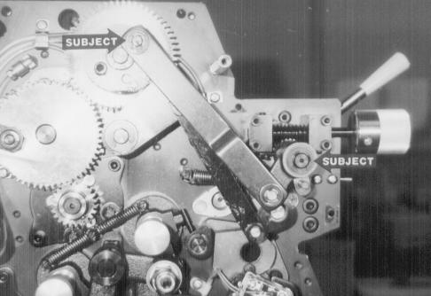
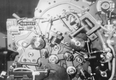
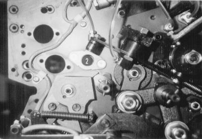
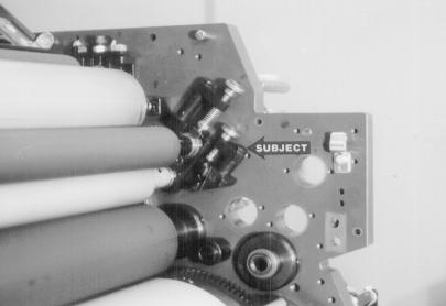
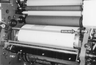
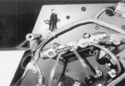
9 DISASSEMBLY 4 Remove the water tray and cloth covered rollers from both printing units. 5 At the OPS, remove "E" clips and washers (subject arrows) from stud and pull off the assembly held by these parts. 6 At the OPS, remove the spring behind the arm (#2, not visible in picture). Remove the "E" clips and washers (subject arrows) and pull the assembly off. 9
10 10
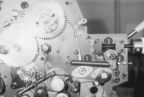
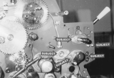
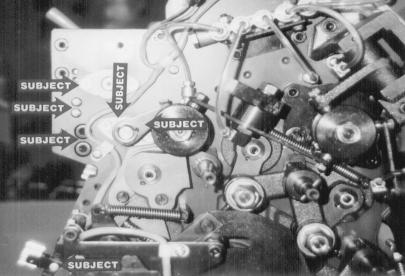
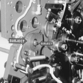
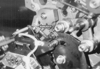
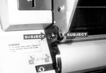
11 DISASSEMBLY 7 At the OPS, remove the spring (#1), housing with clutch (#2), and infinite water control (#3, held on by 4 bolts) from the end of the water fountain roller shaft. (Older models have an arm and ratchet assembly with a gear. Remove these pieces if the press does not have the infinite water control. The gear has a set screw in it that needs to be loosened before you can remove it.) 8 Drive the pin out of the arm (#1) and remove it. Remove all the screws indicated by the subject arrows. The arrows on the left indicate the housings for the metal rollers and ductor. The upper arrow, on the right, is the water pan block, the lower arrow is the tie bar bolts. These are at the OPS. NOTE: A new tie bar will be installed in the press during the dampener installation. 9 Remove the long stop pin from the hosing on the water form night latch shaft (subject arrow). Remove the bolt from the wiper bar (#2). These are located at the OPS. (On older models, the bolt holding the wiper bar is at the NOPS.) Remove the wiper bar. OPTION: You can remove the small screw and clicker plate from the water form adjustment screw block (#1) and replace it with the set screws # provided by Accel. This will secure the form to plate setting once adjusted. NOTE: This picture has the parts already removed. 11
12 12
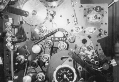
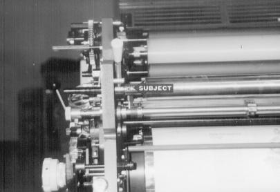
13 DISASSEMBLY 10 Unhook the wires from the solenoid at NOPS (subject arrow) and remove it from the press. 3 screws hold the solenoid. Each screw has a washer and a spacer. Be sure these parts do not fall in the press. 11 At the NOPS, drive the pin out and remove the arm (subject arrow at far right.) Remove the screws near the other subject arrows 12 Remove the nut and spool from the end of the oscillator (subject arrow.) The easiest way to do this is: 1. Rotate the press, by hand, until the oscillator has moved all the way to the NOPS. 2. Remove the nut and lock washer from the end of the oscillator. 3. Remove the oscillator bushing at the OPS and slide the oscillator roller by hand to the OPS. The spool will come off. 13

14 14
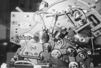
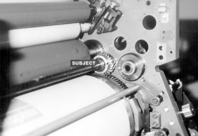
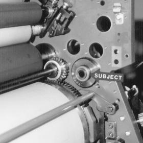
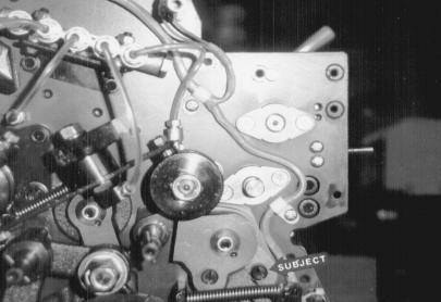
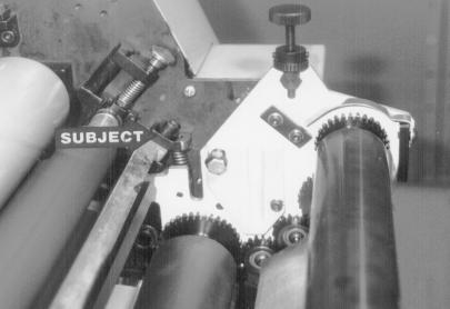
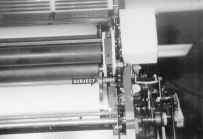
15 DISASSEMBLY 13 Remove the cap screw (subject arrow) holding the two pieces of the water fountain roller together. Remove the bushings from the side frame holding the roller, slide the two pieces apart, and remove the pan roller and extension from the press. NOTE: Older models may have a single piece fountain roller. 14 Remove the 2 screws and bushing (near #2) for the oscillator at the NOPS. Slide the oscillator roller out of the press. 15 The water ductor mechanism (subject arrow) has a series of set screws holding it to the shaft. Loosen all the set screws, including the one in the brass collar in the middle. Remove the bushings holding the shaft in the side frames. Gently tap the shaft towards the OPS until it clears the inside of the press frame. The entire assembly can be removed. 15
16 16
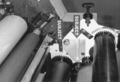
17 DISASSEMBLY 16 Remove the water form night latch shaft as follows: 1. Put the handle on the shaft at NOPS. 2. Knock the pin out and remove the collar on the shaft at the OPS. (Located outside the side frame.) 3. Loosen the two set screws in the collar (subject arrow). 4. Clean the shaft thoroughly and spray with a lubricant. 5. Pull the shaft towards the NOPS to remove shaft, collar and gear. 17 Loosen set screw (left hand subject arrow, left picture). Also loosen lock nut (right hand subject arrow, left picture) and back out set screw almost all the way. Gently tap inner ring (subject arrow, right hand picture) until it is flush with the middle ring. Tighten side screw, spin end play screw back in until it stops and then tighten lock nut. This is only done at the NOPS. 18 Remove the bolt and spring loaded assembly (subject arrow) at OPS and NOPS. 17

18 18
19 DISASSEMBLY INSTALLATION 19 Remove the studs (#2) from inside the press frame. There is one stud in the first printing unit and 3 in the second printing unit. YOU ARE NOW READY TO INSTALL CRESTLINE. 19

20 20
21 INSTALLATION 1 Tighten screw (subject arrow) until it is flush with the cast metal arm it is threaded through. This tightens a spring and prevents the entire housing from moving. Screws are located at OPS and NOPS of both printing units. 2 Reinstall small side covers. On older press also reinstall the small gray plates (not shown) taken off with the small side covers. Note the two holes (subject arrow). These holes are used in step 5. 3 Make sure the pivot stud (subject arrow) is fully tight at OPS and NOPS. Accel recommends removing screw and placing a drop of Loc-tite or similar product on the threads before proceeding. 21

22 22
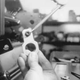
23 INSTALLATION 4 Take the provided aluminum connecting links # and slip the small black eccentric through the small hole in the link and its retaining bolt. Next, slip the link over the molleton form roller housing as shown. 5 The hex portion of the eccentric and the bolt head will face outward. Let the link lie down and rest the bolt head against the opening in the press frame as shown. Install the Crestline mounting block #16-02 as shown in the picture. Make sure that the mounting hole faces down on each side. 6 Place the bolts # , mounting spools and set collars into the mounting blocks as shown (subject arrow). The set collar should be flush against the inside of the mounting block and the spool should not extend past the set collar. 23

24 24
25 INSTALLATION 7 Set the bar # (subject arrow) over the posts which held the spring loaded assembly removed in disassembly step 18. Check the dampener on a cutter bed to see if it is square. 8 Remove the oscillator, intermediates, and metering rollers from dampener. Set the dampener between the press frames as shown, making sure the dampener form gear meshes with the plate cylinder. The front edge of the damepner will rest under the casting where the tie bar rests (Step 7 above). 9 Tighten the mounting bolt (left hand subject arrow). This may misalign the dampener. Make sure the water form is centered relative to the ink forms, then move the set collar (right hand subject arrow) against the mounting block at each side and tighten. 25
26 26
27 INSTALLATION 10 Thread the bolt in the eccentric into the tapped hole in the dampener side frame and finger tighten. The high side of the eccentric (denoted by yellow dot) shold point toward the press feeder. 11 Slip spring # over posts at OPS and NOPS of dampener and secure retainer (subject arrow) to the posts protruding through the new tie bar with the blocks # and bolts #05-128M20 provided. 12 Replace both plate cylinder guards and the inker guards with the new ones provided by Accel. 27
28 28
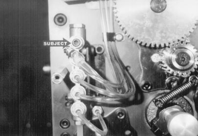
29 INSTALLATION 13 Plug up the oil lines at OPS (picture #1) and NOPS (Picture #2) with the screws #99-24 provided and zip tie the lines. Note how the solenoid wires at NOPS are taped off and tied with the oil line. YOU ARE NOW READY TO MAKE THE FINAL ADJUSTMENTS
30 30
31 FINAL ADJUSTMENTS 1 FORM ROLLER LIFT AND GEAR MESH Make sure the single lever is in the OFF position adjust the dampener lift as follows. Take the provided gap tool and insert between the plate cylinder surface and the under-side of the water form roller shaft. Adjust the eccentric in the connecting link until the proper lift off the plate is obtained and fully tighten the lock bolt. Do this at the OPS and NOPS. 2 INSTALLATION OF ROLLERS Install the rollers in the followig order: 1. Oscillator in slot indicated by left hand subject arrow. 2. Hard intermediate roller in slot indicated by right hand subject arrow. Place pin in set collar to the NOPS. 3. Soft intermediate (same size as hard intermediate) above hard roller. Again, pin in set collar to NOPS. 4. Metering roller beneath thumb screws. Pin in collar should be resting against angle block, towards the ink rollers. 3 MOUNT PLATES AND INK UP THE DAMPENER Mount plates to both cylinders. Dab some ink on the dampener oscillator and idle the press for a while to distribute the ink on the dampener rollers. 31
32 32
33 FINAL ADJUSTMENTS O F Plate Cylinder U UI M 5/32" (4mm) 4 P FORM ROLLER TO PLATE CYLINDER PRESSURE Shut the press off and drop the water form to the plate and back off again. (Form drops by moving single lever handle to water position). The form pressure to the plate should be set at 5/32". (Dropping the form to the plate leaves an ink stripe). Adjust the water form knobs (same ones used to adjust molleton form) until an even 5/32" stripe is achieved. Lock the position of the knobs with the small set screws. A stripe card is provided for your convenience. O F U UI M 5 5/32" (4mm) P MAXIMUM METERING TO PAN ROLLER PRESSURE (Rollers are not shown in the picture) Spin the ratchet gear (which is not attached to the thumb screw at this time) down until it stops against the stud (upper subject arrow). Tighten the thumb screw until pressure is applied between the metering and pan rollers. Idle the press for 20 seconds, then let it sit for 20 seconds. Jogging the press forward reveals a roller pressure stripe. It should be 3/16". Adjust the thumb screws until a 3/16" stripe is obtained. Lock the ratchet gear to the thumb screw with the two small set screws. Plate Cylinder O F Plate Cylinder U 1/8" (3 mm) UI M 6 P METERING TO INTERMEDIATE PRESSURE Adjust the metering to upper intermediate pressure by using the hanger eccentric (lower subject arrow). To view the stripe, idle the press for 20 seconds and then let it sit for 20 seconds. Drop the water form to the plate then rotate the press backwards and view the stripe on the metering roller. The stripe needs to be viewed in this manner because the dampener has clutches that prevent it from rotating backwards. Dropping the water form to the plate friction drives the dampener backwards. Adjust the eccentric until an even 1/8" stripe is obtained. Also see page 40 for a special diagram explaining how to set this pressure. 33
34 34
35 FINAL ADJUSTMENTS 7 Install the water pan and bottle. Set the water level in the pan by adjusting the bottle bracket. Raising the bracket will raise the pan level and vice-versa. Water should be about halfway up the pan. 8 Reinstall the covers on the press. YOU ARE NOW READY TO PRINT. 35
36 BASIC OPERATION START OF DAY A. Make sure the oscillator, lower intermediate and metering rollers are in place. B. Spin knurled knobs until the shoulder on the ratchet stops against the stud bar. C. Place water bottle in bracket. NOTE: Accel recommends using the proper fountain solution for the plate material being run on the press. A good acid/gum etch should be used with metal plates. D. Mount plate to cylinder. Wipe down all plates before running. Pre-ink the Crestline dampender before running the plates with an extremely light coverage of ink. Dab the ink on the oscillator only. RUNNING DURING THE DAY A. In general, the Crestline Dampener should not have to be adjusted from job to job. The form roller setting should never be changed unless it has deviated from the factory specification of 5/32" to the plate. B. Adjustments to the amount of water fed to the plate are made by the knurled knobs that apply pressure to the metering roller. The dampener has been set up for minimum water. To increase the water to the plate, turn the knurled knobs counter clockwise 1 or 2 clicks at a time. This opens the gap between the metering and pan rollers and allows more water to the plate. C. In general, more water will only be required when going from a metal plate to an electrostatic or silvermaster type plate. 36
37 CLEANING & MAINTENANCE WASH UPS DURING THE DAY 1. Remove bottle and drain the excess water from the pan. 2. Mount a metal plate to the press. 3. Turn on the press and squirt a small amount of press wash on the ink rollers. 4. Drop both the dampener and ink forms to the plate. it will be necessary to drop the forms manually rather than by the single lever. In general, the dampener will pick up enough roller wash off the plate to clean itself. Apply wash directly to the dampener only when necessary. 5. Use wash up attachment as normal. The plate cylinder is being used as a bridge between the dampener and inker. Solution transfers from the dampener to the plate, plate to inker, and inker to wash up attachment. 6. Remove water pan and clean any solution left in it. 7. Be sure to wipe excess clean up solution from the ends of the dampener metering and pan rollers. END OF THE DAY 1. Wash up dampener. Pay close attention to cleaning the ends of the pan and metering rollers that extend past the form rollers. 2. Spin the knurled knobs up until the metering roller can be removed. 3. Remove metering roller and wipe down thoroughly to remove any excess wash that may be on the roller. 37
38 CLEANING & MAINTENANCE DEGLAZING THE DAMPENER Periodic deglazing of water-soluble contaminants will be necessary with the Crestline. Typically, once every 2-3 weeks is sufficient, unless you are running electrostatic plates on a daily basis, whereas deglazing should be performed weekly. A 50/50 solution of household ammonia and hot water can be used for deglazing purposes. If you prefer a commercially available deglazer, avoid those containing pumice or gritty substances. Always follow deglazing with straight water and then roller wash. OILING AND GREASING THE DAMPENER A. Place a small amount of grease on the gears once a month. B. Inject grease into the oscillator grease fitting one a month. 38
39 CLEANING & MAINTENANCE CRESTLINE CLEANING & MAINTENANCE CHART Daily Weekly Bi-Weekly Monthly Wash Rollers Deglaze Rollers Metal Plate Users Silvermaster Plate Users Electrostatic Plate Users Grease Gears Inspect Ball Bearings Check Roller Pressures Check Roller Surfaces 39
40 When adjusting the upper intermediate roll to the metering roll, turn the eccentrics in the direction indicated to set the stripe. The stripe between the intermediate and metering roll should be 1/8". 40
41 41 RY332-OPS
42 42
43 43
44 44
45 45
46 46
47 47
48 48
49 49
50 50
51
52 11103 Indian Trail, Dallas, TX Phone , Fax Web Site
Crestline Dampening System
 Crestline Dampening System Installation Instructions Ryobi 3200 MCD Itek 985 X88-31 Rev-A 5/98 GENERAL INFORMATION ATTENTION CRESTLINE DAMPENER OWNER! Accel Graphic Systems provides parts and service through
Crestline Dampening System. Installation Instructions. Hamada RS34 & VS34 Satellite Unit. For Presses Originally Equipped With. Integrated Dampeners
 Crestline Dampening System Installation Instructions Hamada RS34 & VS34 Satellite Unit For Presses Originally Equipped With Integrated Dampeners X88-113 01/2001 Rev-A GENERAL INFORMATION ATTENTION CRESTLINE
Crestline Dampening System. Installation Instructions. A.B. Dick 350, 360, 375 Single & Dual Lever Machines. X /01 Rev-A
 Crestline Dampening System Installation Instructions A.B. Dick 350, 360, 375 Single & Dual Lever Machines X88-20 01/01 Rev-A GENERAL INFORMATION ATTENTION CRESTLINE DAMPENER OWNER! Accel Graphic Systems
Crestline Dampening System. Installation Instructions. Ryobi 500N X /98
 Crestline Dampening System Installation Instructions Ryobi 500N X88-33 7/98 GENERAL INFORMATION ATTENTION CRESTLINE DAMPENER OWNER! Accel Graphic Systems provides parts and service through its authorized
Crestline Dampening System Installation Instructions
 Crestline Dampening System Installation Instructions Hamada RS/ VS 34 II Parent Unit DU 34 II Upper Unit X88-104 Rev-B 01/2001 GENERAL INFORMATION ATTENTION CRESTLINE DAMPENER OWNER! Accel Graphic Systems
Altra Series Dampener
 Crestline TM Altra Series Dampener Installation Instructions Ryobi 512 X88-69 10/98 Rev-A GENERAL INFORMATION ATTENTION CRESTLINE ALTRA SERIES TM DAMPENER OWNER! Accel Graphic Systems provides parts and
Crestline Altra TM Series Dampener. Installation Instructions. Didde MCP/Conserver. X /2001 Rev-A
 Crestline Altra TM Series Dampener Installation Instructions Didde MCP/Conserver X88-55 01/2001 Rev-A GENERAL INFORMATION ATTENTION CRESTLINE ALTRA TM SERIES DAMPENER OWNER! Accel Graphic Systems provides
Crestline Altra Series TM Dampener. Installation Instructions. Heidelberg GTO. X /98 Rev-A
 Crestline Altra Series TM Dampener Installation Instructions Heidelberg GTO X88-63 7/98 Rev-A GENERAL INFORMATION ATTENTION CRESTLINE ALTRA SERIES TM DAMPENER OWNER! Accel Graphic Systems provides parts
PowderPro Spray System
 PowderPro Spray System Installation Instructions Hamada C248 X88-72 10/98 REV-C 2657 GENERAL INFORMATION ATTENTION POWDERPRO OWNER! Accel Graphic Systems provides parts and service through its authorized
Roller Removal Instructions
 Roller Removal Instructions Rollers for the Crestline dampener are broken down into numerical categories as follows: Prefix Roller Position Prefix Roller Position x07-01.. Form Roller x07-04.. Oscillator
HYDRAULICS. TX420 & & lower. Hydraulic Tandem Pump Removal. 4. Remove the LH side panel (Fig. 0388).
.") TX420 & 425 240000299 & lower 4. Remove the LH side panel (Fig. 0388). Hydraulic Tandem Pump Removal Note: Cleanliness is a key factor in a successful repair of any hydraulic system. Thoroughly clean all
TX420 & 425 240000299 & lower 4. Remove the LH side panel (Fig. 0388). Hydraulic Tandem Pump Removal Note: Cleanliness is a key factor in a successful repair of any hydraulic system. Thoroughly clean all
CALIFORNIA TRIMMER MOWER MAINTENANCE MANUAL
 CALIFORNIA TRIMMER MOWER MAINTENANCE MANUAL 2 Table of Contents Section 1: General Information Page Handle Assembly Instructions 4 Maintenance All Models 6 Oil Change Procedures All Models 9 Height Adjustment
DRIVE AXLE Volvo 960 DESCRIPTION & OPERATION AXLE IDENTIFICATION DRIVE AXLES Volvo Differentials & Axle Shafts
 DRIVE AXLE 1994 Volvo 960 1994 DRIVE AXLES Volvo Differentials & Axle Shafts 960 DESCRIPTION & OPERATION All 960 station wagon models use type 1041 rear axle assembly. All 960 4-door models use type 1045
Sachs 48mm Closed Cartridge fork Service Manual
 Sachs 48mm Closed Cartridge fork Service Manual 1 Fork seal driver 2 Special soft jaws 3 Fork cap wrench 4 Rebound rod holding tool 5 Compression assembly holding tool 6 Retaining clip tool Special Tools
Tel/Fax: Replacement parts for : MULTI 1210, 1250OS, 1250W, 1250N, 1250DOM.
 Replacement parts for : MULTI 1210, 1250OS, 1250W, 1250N, 1250DOM., 1215CD, VARIABLE SPEED PULLEY 1250 O.S. - 1/2 Shaft P-1629 1250 N.S. - 5/8 Shaft P-1649 V-BELTS 35 Motor to printing head P-4904 33 Pump
Installation Manual TWM Performance Short Shifter Cobalt SS/SC, SS/TC, HHR SS, Ion Redline and Saab 9-3
 Page 1 Installation Manual TWM Performance Short Shifter Cobalt SS/SC, SS/TC, HHR SS, Ion Redline and Saab 9-3 Please Note: It is preferable to park on a flat surface, as you will have to engage and disengage
The steering column is of a modular construction and features easy to service electrical switches.
 file://c:\tso\tsocache\vdtom_5368\svk~us~en~file=svkb4a01.htm~gen~ref.htm Page 1 of 3 Section 11-04A: Steering Column, Ranger DESCRIPTION AND OPERATION 1997 Ranger Workshop Manual Steering Column NOTE:
Installation Instructions
 Installation Instructions (2) 10-24 Black flathead Allen Screws Tailgate End Front Cover Passenger Side Rail (has inspected by sticker under rail) (4) 10-32 Screws (stainless) Front Cover Exploded View
Installation Manual TWM Performance Short Shifter Subaru STi 2008+
 - 1 - Installation Manual TWM Performance Short Shifter Subaru STi 2008+ Please Note: It is preferable to park on a flat surface, as you will have to engage and disengage the hand brake and shift from
N41421 Peacemakers Exhaust for Harley- Davidson Dyna Series
 Please read these instructions carefully and thoroughly before beginning work. Before installing accessory, carefully consider whether one possesses the necessary technical skills and workshop tools to
Maintenance Information
 80234313 Edition 1 June 2006 Air Grinder, Die Grinder, Sander and Belt Sander Series G1 (Angle) Maintenance Information Save These Instructions WARNING Always wear eye protection when operating or performing
Installation Instructions COMPETITION/PLUS SHIFTER Ford Mustang MT82 6-Speed Manual Transmission Catalog#
 Installation Instructions COMPETITION/PLUS SHIFTER 2015-2017 Ford Mustang MT82 6-Speed Manual Transmission Catalog# 3916037 Rev. 00 WORK SAFELY! For maximum safety, perform this installation on a clean,
Maintenance Information
 16573370 Edition 2 February 2014 Air Grinder 99V Series Maintenance Information Save These Instructions Product Safety Information WARNING Failure to observe the following warnings, and to avoid these
Maintenance Information
 80234313 Edition 2 May 2014 Air Grinder, Die Grinder, Sander and Belt Sander Series G1 (Angle) Maintenance Information Save These Instructions Product Safety Information WARNING Failure to observe the
CARD RECORDER MECHANISMS
 ITR Engineering Data Sheet 201 September 1927 CARD RECORDER MECHANISMS Card time recorders are used for registering on a card the time that employees enter and leave the factory. The card and the recorder
CHAINGUARD REGAL ST COLOR
 DESOTO/ REGAL HAULER PARTS LIST Item Part # Description QTY Item Part # Description QTY 1 11871 REFLECTOR KIT TRIKE 1 32 11764 FENDER BRACE 24" MWT 1 2 12199 SCREW #14 x 3/4 4 33 12176 NUT5/16-24 HEX 2
Same Day Service ORDERS RECEIVED BY 2 P.M. WILL BE SHIPPED THE SAME DAY. Top Quality Low Prices REPLACEMENT PARTS CATALOG PART #P-AA $ 50.
 REPLACEMENT PARTS FOR OFFSET PRINTING PRESSES 15th. REVISED EDITION DECEMBER, 2005 Same Day Service ORDERS RECEIVED BY 2 P.M. WILL BE SHIPPED THE SAME DAY Top Quality Low Prices $ 50.00 350 9840 9870 360
phone
 AS-25-59 Ball AS-035508 Pinion Housing AS-035512 AS-036552 Ink Fountain Adjusting Screw AS-053111 Cam Follower sliding block fountain AS-085015 AS-087459 Idler Gear AS-1001705 Set Screw AS-1023953 Top
DESCRIPTION Acura TSX SUSPENSION Front - TSX. NOTE: For system description and component location, see Fig. 1.
 2004 SUSPENSION Front - TSX DESCRIPTION NOTE: For system description and component location, see Fig. 1. Fig. 1: Identifying Front Suspension Components Wednesday, March 12, 2008 8:30:45 8:30:55 PM Page
Slave Cylinder Weep Hole Drilling Procedure
 Slave Cylinder Weep Hole Drilling Procedure Tools Required: T20 Torx Driver T25 Torx Driver T25 Torx Bit with ¼ Ratchet Wrench 4mm Hex Key (Allen wrench) 5mm Hex Key 6mm Hex Key 8mm Hex Key 12mm Hex Key
CHAINGUARD REGAL ST COLOR
 DESOTO/ REGAL HAULER PARTS LIST Item Part # Description QTY Item Part # Description QTY 1 11871 REFLECTOR KIT TRIKE 1 32 11762 FENDER BRACE 20" MWT 1 2 12199 SCREW #14 x 3/4 4 11764 FENDER BRACE 24" MWT
FlexJet Carriage Circuit Board (PCB) Replacement
 Replacement") P/N: 111484 R0 14140 NE 200th St. Woodinville, WA. 98072 PH: (425) 398-8282 FX: (425) 398-8383 ioline.com FlexJet Carriage Circuit Board (PCB) Replacement Notices: Warning! Ensure that all AC power cables
P/N: 111484 R0 14140 NE 200th St. Woodinville, WA. 98072 PH: (425) 398-8282 FX: (425) 398-8383 ioline.com FlexJet Carriage Circuit Board (PCB) Replacement Notices: Warning! Ensure that all AC power cables
Document: 3 inch Vane Pump System-in-a-Box Assembly Instructions SPS100370
 1.0 What is a System-in-a-Box? System-in-a-Box for 3 inch vane pumps (SPSZRS-V3N VANE SYS KIT) contains all of the castings, mounting plates and hardware that make up the base system, with the exception
Short Shifter Installation Instructions For Miata, 6-speed Manual Transmission
 Short Shifter Installation Instructions For 2006-15 Miata, 6-speed Manual Transmission PART# 994-060 Required tools: 10mm deep socket Long extension Ratchet Small flathead screwdriver Phillips-head screwdriver
AmTryke Adult Recumbent Model JT2000 #50-FC-2000
 AmTryke Adult Recumbent Model JT2000 #50-FC-2000 TOOLS Needed for Assembly 5 mm Allen Wrench 8 mm Socket or Wrench 10 mm Socket or Wrench 14 mm Socket or Wrench 15 mm Socket or Wrench 22 mm Socket or Adjustable
Maintenance Supplies
 Maintenance Supplies 7. 8. 6. 15. 14. 13. 12. 10. 9. 2. 3. 5. 4. 11. 1. 1. TU-3 shown for demonstration purposes 2. Teflon tape 3. Center punch 4. 5/32 punch 5. 1/4 punch 6. 3/8 punch 7. Breaker bar with
AmTryke Adult Recumbent Model HP1000 #50-HC-1000
 AmTryke Adult Recumbent Model HP1000 #50-HC-1000 TOOLS Needed for Assembly 5 mm Allen Wrench 8 mm Socket or Wrench 10 mm Socket or Wrench 14 mm Socket or Wrench 15 mm Socket or Wrench 22 mm Socket or Adjustable
INSTALLATION INSTRUCTIONS FOR DSP9600/9100 WHEEL BALANCER
 Form 5063T, 06-05 Supersedes Form 5063T, 02-04 INSTALLATION INSTRUCTIONS FOR DSP9600/9100 WHEEL BALANCER This document provides the information needed to install the DSP9600/9100 Wheel Balancer. NOTE:
SERVICE PARTS LIST. SPECIFY CATALOG NO. AND SERIAL NO. WHEN ORDERING PARTS M18 FUEL SAWZALL Reciprocating Saw STARTING SERIAL NO.
 47(5x) 46 45 00 44 0 59 43 42 84 EXAMPLE: Component Parts (Small #) Are Included When Ordering The Assembly (Large #). CATALOG NO. 2720-20 51 57 46 47 48 59 83 64 77 48 47(2x) 49(2x) 40 58 41 82 51 40
SERVICE PARTS LIST. M18 FUEL ONE KEY SAWZALL Reciprocating Saw H31A BULLETIN NO
 00 FIG. PART NO. DESCRIPTION OF PART NO. REQ. 1 45-12-0040 Gearcase Insulator 1 2 40-50-8805 Extension Spring 1 3 31-11-0105 Barrel Cam 1 4 34-60-3700 Retaining Ring 1 5 --------------- Front Cam 1 6 ---------------
Service Instruction Front Suspension PASHLEY-MOULTON. 1.0 General Description. 2.0 Adjustment
 Service Instruction Front Suspension PASHLEY-MOULTON 1 General Description 2 Adjustment 3 Problems and their Remedies 3.1 Clunking or Banging Noises 3.2 Suspension Squeaking 3.3 Seized Suspension 4 Disassembly
SUZUKI SQ 416/420/625 M.Y TRANSMISSION SERVICE MANUAL - MANUAL - AUTOMATIC - TRANSFER - DIFFERENTIALS
 SUZUKI SQ 416/420/625 M.Y 1998-2005 TRANSMISSION SERVICE MANUAL - MANUAL - AUTOMATIC - TRANSFER - DIFFERENTIALS WARNING/CAUTION/NOTE IMPORTANT Please read this manual and follow its instructions carefully.
Installation Manual TWM Performance Short throw shifter 2001 and up Hyundai Accent
 Installation Manual TWM Performance Short throw shifter 2001 and up Hyundai Accent 1. Place the vehicle on a flat surface with blocks in front and behind the wheels preventing unwanted movement. The car
Sachs shock manual. ( ) 2 & 4 Stroke RR Enduro. ( ) RS Dual Sport
 2 & 4 Stroke RR Enduro. ( ) RS Dual Sport") Sachs shock manual (2013 2015) 2 & 4 Stroke RR Enduro (2014-2015) RS Dual Sport 1 Introduction The procedures in this manual must take place in a clean environment using professional tools and some specific,
Sachs shock manual (2013 2015) 2 & 4 Stroke RR Enduro (2014-2015) RS Dual Sport 1 Introduction The procedures in this manual must take place in a clean environment using professional tools and some specific,
PLEASE READ ALL INSTRUCTIONS BEFORE INSTALLATION
 1 68 RFE VALVE BODY UPGRADE Part #: 1030360 Part #: 1030361 2007-11 (Early Model) 2010-12 (Late Model) PLEASE READ ALL INSTRUCTIONS BEFORE INSTALLATION 2 K I T C O N T E N T S : Please check to make sure
INSTALLATION INSTRUCTIONS FOR THE MOTOR TRIKE CROSS COUNTRY / CROSS ROADS / HARD BALL RAKE KIT
 INSTALLATION INSTRUCTIONS FOR THE MOTOR TRIKE CROSS COUNTRY / CROSS ROADS / HARD BALL RAKE KIT Thank you for choosing the Motor Trike Cross Country / Cross Roads / Hard Ball rake kit. We ask that you read
Maverick American 3085 Bluff Street Boulder, CO Tel: Fax: ML7.2 SHOCK SERVICE MANUAL
 Maverick American 3085 Bluff Street Boulder, CO 80301 Tel: 303-415-0370 Fax: 303-415-0676 www.maverickamerican.com ML7.2 SHOCK SERVICE MANUAL 1. OVERVIEW 1.1. The Maverick ML7.2 rear shock is an oil damped
CONTROL SYSTEM FOR THE PHYSICALLY DISABLED
 INSTALLATION Push/Rock HAND CONTROL SYSTEM FOR THE PHYSICALLY DISABLED With Howell Ventures Ltd Sure Grip Hand Control Systems and Accessories are warranted against manufacturing or material defects for
Tooling Assistance Center
 Safeguards are designed into this application equipment to protect operators and maintenance personnel from most hazards during equipment operation. However, certain safety precautions must be taken by
Transmission Overhaul Procedures-Bench Service
 How to Assemble the Lower Reverse Idler Gear Assembly Special Instructions In 1996 Eaton changed the reverse idler system design. In the nut design, the reverse idler bearing was lubricated through a hole
Section 5: Parts Replacement
 Section 5: Parts Replacement Should the STAR TRAC 4500 Treadmill experience a problem requiring replacement of a specific part, the following procedures will help and instruct in the replacement of major
SERVICE INSTRUCTIONS ASSEMBLY & DISASSEMBLY T50X DOUBLE ACTING HYDRAULIC SERIES ACTUATORS
 Page 1 of 7 SERVICE INSTRUCTIONS ASSEMBLY & DISASSEMBLY T50X DOUBLE ACTING HYDRAULIC SERIES ACTUATORS INTRODUCTION This service procedure is offered as a guide to enable general maintenance to be performed
9905/9910/9910D/ 9910XCS/9910XC2 Service Reference Manual
 9905/9910/9910D/ 9910XCS/9910XC2 Service Reference Manual 1996, A.B.Dick Company P/N 177187 (REV. 0) WARNING: This equipment must be connected to a properly grounded three (3) wire outlet. Failure to do
Final Assembly Instructions: Runaround Cruiser
 Final Assembly Instructions: Runaround Cruiser Thank you for buying your new bicycle from L.L.Bean. Read these instructions carefully before beginning the final assembly. Prior to shipping, our expert
Installation Manual TWM Performance Short Shifter 2008 Mitsubishi Lancer
 Page 1 Installation Manual TWM Performance Short Shifter 2008 Mitsubishi Lancer Please Note: It is preferable to park on a flat surface, as you will have to engage and disengage the hand brake and shift
Maintenance Information
 16575219 Edition 4 October 2013 Air Screwdrivers QP1P, QP1S and QP1T Series Maintenance Information Save These Instructions Product Safety Information WARNING Failure to observe the following warnings,
X-Trainer 43mm fork service manual. Beta USA, Inc This work should be performed by a trained motorcycle technician.
 X-Trainer 43mm fork service manual Beta USA, Inc. 2016 This work should be performed by a trained motorcycle technician. Table of contents Page Introduction/special tools... 2 Fork exploded view... 3 Legend.
Maintenance Information
 16584062 Edition 3 December 2013 High Torque Reversible Angle Screwdrivers and Angle Wrenches QA1L High Torque Series Maintenance Information Save These Instructions Product Safety Information WARNING
Maintenance Information
 04581245 Edition 2 May 2014 Air Grinder, Die Grinder and Sander Series G2 (Angle) Maintenance Information Save These Instructions Product Safety Information WARNING Failure to observe the following warnings,
PRO RATCHET UNIVERSAL SHIFTER
 Installation Instructions PRO RATCHET UNIVERSAL SHIFTER Fits: GM, Ford and Chryslers w/automatic Transmission See Application Guide for Specific Vehicles Catalog # 80842 WORK SAFELY! For maximum safety,
POWER STEERING PUMP REBUILDING SPK101 Read instructions completely before removal & disassembly
 POWER STEERING PUMP REBUILDING SPK101 Read instructions completely before removal & disassembly DISASSEMBLY: 1. Remove pump from car and allow to drain. 2. Remove pulley from front of pump. This requires
phone
 AS-25-59 Ball AS-035508 Pinion Housing Bearing AS-035515 Bearing AS-036552 Ink Fountain Adjusting Screw AS-051120 Bearing call for details AS-053111 Cam Follower AS-087047 Bearing Hanger Bracket Assembly
"Engineered to Ride, Built to Last "
 Congratulations on your purchase of an Arnott air suspension product. We at Arnott Incorporated are proud to offer a high quality product at the industry s most competitive pricing. Thank you for your
INSTALL MANUAL. FOR ON LINE ORDERING- E Commerce Visit Our Website
 INSTALL MANUAL FOR ON LINE ORDERING- E Commerce Visit Our Website WWW.PRESSUREGUARD.COM Contact Information Technical Support: Chris@pressureguard.com Sales Support: Sales@pressureguard.com By Phone: 615-227-6024
Assembly Manual. 1/10th Formula 1 Car
 Assembly Manual 1/10th Formula 1 Car Center Pivot Bag 1 3374 - Center Pivot Socket 40194 - Hard Anodized Alum Pivot ball 3254-2-56 *Note - Sometimes it is helpful to slightly over-tighten the top clamp
Installation Manual TWM Performance Short Shifter Nissan 350Z, 370Z Infiniti G35, G37
 Installation Manual TWM Performance Short Shifter Nissan 350Z, 370Z Infiniti G35, G37 It is preferable to park on a flat surface, as you will have to engage and disengage the hand brake and shift from
RHINO SUSPENSION SYSTEM INSTALLATION INSTRUCTIONS
 PARTS INCLUDED: 2 FRONT UPPER A-ARMS 2 FRONT LOWER A-ARMS 2 UNI-BALL JOINTS 2 UNI-BALL JOINT STUDS 2 UNI-BALL JOINT CAPS 2 RETAINING RINGS 1 FRONT SHOCK ASSEM. 2 DELRON STEERING STOPS 2 SHOCK MOUNT SPACERS
Max IV Rear Axle Replacement For models after Serial Number and all rear splined axle replacements.
 Max IV Rear Axle Replacement For models after Serial Number 19089 and all rear splined axle replacements. 10/8/03 Max IV Snap Ring Rear Axle replacement.doc Tools required: 9/16 Wrench 6 Extension Steel
Prusa i3 Printer Assembly Guide
 Prusa i3 Printer Assembly Guide Special thanks to Carlos Sanchez and Miguel Sanchez for the graphics. All graphics captured from their great animation: http://www.carlos-sanchez.com/ Prusa3/ For copyright
INSTALLATION INSTRUCTIONS DRAWERS #240
 INSTALLATION INSTRUCTIONS DRAWERS #240 Please read and fill out the enclosed warranty registration card to activate your warranty. SHIPMENT CONTENTS #1 Lid #2 Rear #3 Left side panel #4 Right side panel
1989 Jeep Cherokee. STEERING COLUMN' '1989 STEERING Jeep Steering Columns STEERING COLUMN STEERING Jeep Steering Columns
 STEERING COLUMN 1989 STEERING Jeep Steering Columns DESCRIPTION All models use collapsible steering columns. All columns have integral ignition switch and locking device. Optional tilt wheel is available
Maverick American 3085 Bluff Street Boulder, CO Tel: Fax: ML7.0 SHOCK SERVICE MANUAL
 Maverick American 3085 Bluff Street Boulder, CO 80301 Tel: 303-415-0370 Fax: 303-415-0676 www.maverickamerican.com ML7.0 SHOCK SERVICE MANUAL 1. OVERVIEW 1.1. The Maverick ML7.0 rear shock is an oil damped
Your G3 buggy is fitted with three switches on the front part of the body:
 CONTENTS Buggy operation... 3 General Maintenance... 5 Technical Maintenance... 6 Front wheel bearing replacement... 6 Rear wheel bearing replacement... 7 Chain replacement... 8 Chain Adjustment... 9 Brake
INSTALLATION & OWNER S MANUAL
 Rev. E p. of 3 INSTALLATION & OWNER S MANUAL V446 Front Cab Kit and V446 Rear Cab Kit for RTV 40 INSTALLATION & OWNER S MANUAL The contents of this envelope are the property of the owner. Be sure to leave
Please try our way first.
 1958-1962 Corvette Raingear installation instructions Designer s Note: The 1958-1962 Corvette RainGear wiper system that you have purchased is complex and will require patient fitting. Complete Instructions
phone
 AS-035508 Pinion Housing AS-035511 AS-035512 AS-040502 AS-040504 Locknut sliding block fountain AS-053111 Cam Follower AS-082220 Lockwasher AS-085015 AS-087459 Idler Gear AS-1001705 Nylon Tip Set Screw
ALL AMERICAN BILLET. Front Drive System - Small Block Ford Installation Instructions
 ALL AMERICAN BILLET Front Drive System - Small Block Ford Installation Instructions Small Block Ford with AC & PS All American Billet Store (800) 764-0926 www.allamericanbilletstore.com Items needed for
Subaru 5-Speed Double Adjustable Short Throw Shifter
 Subaru 5-Speed Double Adjustable Short Throw Shifter 1999+ Subaru Impreza 5-Speed 2004-2005 Subaru Forester XT 5-Speed Congratulations on your purchase of the COBB Tuning Double Adjustable Short Throw
Easy Cover. Installation Instructions. Attention Dealers: Please give this owners manual to the customer when the product is delivered.
 Serving the Truck & Trailer Industry Since 1944 Model 9 10 Spring Flange Mount Easy Cover Attention Dealers: Please give this owners manual to the customer when the product is delivered. Call 800-3-94
Next, chase the threads in the lower A-arm mounts with the 5/8-18 tap and blowout any remaining particles.
 Next, chase the threads in the lower A-arm mounts with the 5/8-18 tap and blowout any remaining particles. Now, apply some anti-seize to the threads of the pivot stud. Also put anti-seize inside the bore
Southwest Windpower Instruction Sheet AIR-X Circuit Replacement Kit
 Southwest Windpower Instruction Sheet AIR-X Circuit Replacement Kit Tools Required 5 / 32 Hex key 5 / 16 Hex key 7 / 64 Hex key Standard screwdriver Pair of external snap ring pliers Rubber mallet Hammer
Part # Regulator Rebuild Kit for SuperFlow and SuperFlow 350 Regulators
 Part #525-309 Regulator Rebuild Kit for SuperFlow and SuperFlow 350 Regulators Tools Required Part Number Description Qty 510-011 O-ring 1 510-014 O-ring 1 510-552 Exhaust Valve 1 510-553 Diaphragm 1 520-032
Installation Instructions for the EVO3 Height-Adjustable Ultimate Short Shifter
 Installation Instructions for the EVO3 Height-Adjustable Ultimate Short Shifter for 1992-2005 325, 323, 318 and 1986-1994 525, 528, 535, 540 5-speed models only. (part number USSE3 and USSE5) Thank you
Service Manual. #19 Gearmatic Winch
 Allis Chalmers Service Manual #19 Gearmatic Winch Service Manual THIS IS A MANUAL PRODUCED BY JENSALES INC. WITHOUT THE AUTHORIZATION OF ALLIS CHALMERS OR IT S SUCCESSORS. ALLIS CHALMERS AND IT S SUCCESSORS
2015 Mustang Lightbar (All Models) CDC#
 CDC#") 2015 Mustang Lightbar (All Models) CDC# 1511-7000-01 Components: 1 CDC Lightbar Note: READ instructions before starting installation!!! CDC Part# Driver side bracket 0511-6001-05 Passenger side bracket
2015 Mustang Lightbar (All Models) CDC# 1511-7000-01 Components: 1 CDC Lightbar Note: READ instructions before starting installation!!! CDC Part# Driver side bracket 0511-6001-05 Passenger side bracket
Easy Cover. Installation Instructions. Attention Dealers: Please give this owners manual to the customer when the product is delivered.
 Serving the Truck & Trailer Industry Since 944 Easy Cover Attention Dealers: Please give this owners manual to the customer when the product is delivered. Call 00-3-94 www.aeroindustries.com Indianapolis,
INSTALLATION INSTRUCTIONS FOR THE MOTOR TRIKE GL1500 RAKE KIT
 INSTALLATION INSTRUCTIONS FOR THE MOTOR TRIKE GL1500 RAKE KIT Thank you for choosing the Motor Trike GL1500 Rake Kit. We ask that you read the directions before you start and follow them very closely.
Difficulty Grading expert Wrench Time 1 hour Tip, Strip or Tune Strip Spares Needed Oil Seals 4.99 (pr), Dust Seals 5.75 (pr)
, Dust Seals 5.75 (pr)") URFNVKR[VHUYLFH Difficulty Grading expert Wrench Time 1 hour Tip, Strip or Tune Strip Spares Needed Oil Seals 4.99 (pr), Dust Seals 5.75 (pr) 22mm socket Rubber mallet Allen keys Small Phillips screwdriver
URFNVKR[VHUYLFH Difficulty Grading expert Wrench Time 1 hour Tip, Strip or Tune Strip Spares Needed Oil Seals 4.99 (pr), Dust Seals 5.75 (pr) 22mm socket Rubber mallet Allen keys Small Phillips screwdriver
Installation Manual TWM Performance Short Shift Kit Stage 1 and Stage 2 MazdaSpeed 6
 Page 1 Installation Manual TWM Performance Short Shift Kit Stage 1 and Stage 2 MazdaSpeed 6 Please Note: It is preferable to park on a flat surface, as you will have to engage and disengage the hand brake
DYNATRAC THE PERFORMANCE AXLE SPECIALIST
 DYNATRAC THE PERFORMANCE AXLE SPECIALIST DynaLoc Installation Instructions, Appendix A iinformation: Dynatrac has included an additional bushing in the DynLoc kit. Part DA60-0022-L will be referred to
Step 4: Remove rear fuel line banjo bolt. Be sure to catch copper washer between pump and front of the rear fuel line.
 Denny T AFC Delete Installation Instructions Tools Needed: 10mm Wrench, 13mm Wrench, 12mm Wrench, 14mm Wrench, 17mm Wrench 5mm Ball End Allen Wrench, 8mm Allen Wrench Needle Nose Pliers, Hammer, Small
RAMPAGE POWER LIFT RAMP
 RAMPAGE POWER LIFT RAMP INSTALLATION AND OPERATING INSTRUCTIONS (3/10/07) The Rampage Power Lift Ramp is the fast, easy, and safe way to load a motorcycle into a truck. One person can load or unload a
C15C C15C. Page 1 of 20
 2 x Lid Front Hinge 1135 8 x M8 Bolt 8 x M8 Washer (3mm Thick) 4 x M6 Large washers 4 x M6 Spring washers 4 x M6 x 40mm Bolts 6 x M6 20mm Bolts 6 x M6 Washers 20 x Screws 2 x Lid mount gas strut bracket
INSTALLATION INSTRUCTIONS
 Accessory Application Publication No. INSTALLATION INSTRUCTIONS HEATED GRIPS P/N 08T71-MKK-D00 After 17 CRF1000L/LD Honda Dealer: Please give a copy of these instructions to your customer. MII 16656 Issue
$1.00 FOR THE TQIO/RCIO
 $1.00 FOR THE TQIO/RCIO m mm HDBBYSHOP Champion Jay Halsey has an impressive track record. One of Jay's advantages is a whisper smooth tranny thanks to his dad, Jim. Now you can build a Halsey transmission!
REPAIR MANUAL URW SERIES. URW-6, 8, 9, 10 & 12 Series Repair Manual
 REPAIR MANUAL URW SERIES URW-6, 8, 9, 10 & 12 Series Repair Manual Contents Page 1. Tools Needed for Repair 1 2. Disassembly and Reassembly of the Cam Casing 2-4 3. Disassembly and Reassembly of the Gear
Chrysler 46RE, 46RH, 47RE, 47RH SURE CURE KIT
 Chrysler 46RE, 46RH, 47RE, 47RH SURE CURE KIT PART NUMBER SC-46-47RHE-OS INSTALLATION GUIDE Parts are labeled here in order of installation. See other side of sheet for details on Sure Cure kit contents.
PIKE DUAL AIR PICTORIAL INSTRUCTIONS. INSTRUCTIONS FOR INSTALLING ENDURO FORK SEALS AND CHANGING SEMI-BATH OIL in RockShox PIKE Dual Air Forks
 INSTRUCTIONS FOR INSTALLING ENDURO FORK SEALS AND CHANGING SEMI-BATH OIL in RockShox PIKE Dual Air Forks RECOMMENDED PARTS AND TOOLS -Bicycle work stand -Plastic bucket/drain pan -5mm Allen wrench -DH
2013 RT / 2014RT / 2015 RT - Shock Spring Adjuster Installation Instructions
 2013 RT / 2014RT / 2015 RT - Shock Spring Adjuster Installation Instructions Billet Aluminum Adjusters (2) Shock Spring Compressors (Optional) Spanner Wrench (1) BajaRon Decals Not Shown (4) Adjuster Scuff
8G Brake Assembly Alignment
 8G Brake Assembly Alignment 8G (9-5250) This document explains how to do the 8G (9-5250) brake assembly alignment in order to eliminate noise in the drive system coming from the mis-aligned brake plates.