Rear Diffuser Increases Downforce With Minimum Extra Drag
|
|
|
- Morgan Cook
- 5 years ago
- Views:
Transcription


1 W A Technology C7 Rear Diffuser Rear Diffuser Increases Downforce With Minimum Extra Drag Several aerodynamic devices can increase downforce, such as rear spoilers. However, spoilers also significantly increase drag that takes power to overcome. For example, the Z06 Stage 3 aero, large spoiler, with full width wicker, is the main reason for the 35% higher drag compared to the base Z06 with smaller spoiler. A diffuser is a shaped section of the car underbody which improves the car's aerodynamic performance by enhancing the transition between the high-velocity airflow underneath the car and the much slower freestream airflow of the ambient atmosphere. This speeds up the airflow underneath the car, which using Bernoulli s principles creates reduced pressure. A greater difference in pressure between the upper and lower surfaces of the car means more downforce, allowing faster cornering with minimum extra drag. Diffuser Design is Complex The fins or fences as they are referred to are important to the diffusers performance. There are two counter-rotating vortices formed along the fence surfaces. The flow is separated and this has a positive effect on flow quality and downforce performance. In the graph at right, suffice for our purposes to note the line in red is the downforce over a wide range of heights from the bottom of the car over the road. That is the performance when fences are present. The blue line is he downforce without fences and with more chaotic flow than when the counter-rotating vortex flow is present. It has a lower peak downforce over a narrow range and only a low height over the road. If you want to work for a F1 team there is much theory and math to master! Copyright by WA Technology, LLC GUttrachi@aol.com Page 1
 AND this PDF - then it s a 2 wrench effort!")
 and 3 supplied bolts in each of the 4 fences as they are called.")


2 Install C7 Carbon Diffuser Install of the C7 Carbon Diffuser is a 3 of 5 wrench difficulty unless you carefully read the modified C7 Carbon instructions (attached) AND this PDF - then it s a 2 wrench effort! Tools: 7 & 10 mm Sockets; a 7 mm open end wrench; Torx T15, T20 &T25; Plastic Trim Tools The Diffuser uses exiting bolts including those outside ends (red circle) and 3 supplied bolts in each of the 4 fences as they are called. These allow the air under the car to merge more smoothly with the air behind the car. The included Undertray extends the smooth path in the center of the car to assist air entering the rear Diffuser. UNBOXING: The box holding the Diffuser and Undertray is 6 feet long. The product is very well packed My experience with a C7 Carbon splitter installed on my 2014 Z51 was the same, excellent packing and well protected. No damage. It has flexible foam padding covered by bubble wrap. The carbon flash painted finish is excellent. Perfect match to the OEM diffuser bottom. It has 4 added fins or properly called Fences. This gives 12 surfaces that will form counter rotating Vortex flow on each fence wall. This makes flow smoother and regular compared to the more turbulent flow without them. Copyright by WA Technology, LLC GUttrachi@aol.com Page 2


3 These are the screws under the back of each fender. The one in Red holds the GM Splash Guard in the Grand Sport and Z06 and the one circled in Red, the splash guard. The inner most Green circled bolt holds the Splash Guard for C7s with narrow rear fenders! I now see how this one part fits all C7s! The inner bolts are on all C7s and are at the same spacing regardless of model! Prior to performing the C7 Carbon Instruction Step 3, I checked the fit. Placed the Diffuser on two 6-inch-high stanchions I had available. Could use cardboard boxes etc. It is not heavy, 10.5 pounds, but it is awkward. Best not to lift the car at this point. In fact not needed until installing the undertray. Found it would hold with one bolt on each side. However, to get it to fit flush for accurate marking and to check the fit of the Fences I used a scissor jack to hold the Diffuser so the fences fit tightly. There was a good fit. So ready for the Step 3 & 4 measuring for and drilling the 12 holes in the OEM diffuser. Wondered why they would not just support the assembly with OEM bolts and perhaps two-sided tape? However, those 6 bottom auto body bolts are small like sheet metal screws! Much stronger to have bolts holding each Fence to the OEM Diffuser. It s a secure assembly with the supplied 1.9-inch OD plastic washers to support added downforce. Copyright by WA Technology, LLC GUttrachi@aol.com Page 3


 Anticipating the small clay balls (recommend for possible use by C7 Carbon) and the drop of paint placed on top of each may not work, so also used another method!")
4 I suggest you watch 1 minute of this video starting at 2:30 in to 3:30: l+corsa+exaust+c7+corvette&&view=detail&m id=3b1ab478b4859af42e933b1ab478b4859 AF42E93&&FORM=VRDGAR However, don t get the wrong impression! It will take up to 1 hour to remove the OEM part that you ll see done in one minute! Will spend a number of pics on Step 3 and Step 4 as these were probably the most difficult to perform properly. Tried several methods of the simple statement in Step 3, Add marking material on the predrilled holes. As well as marking the OEM diffuser for drilling. Devised a method that worked. Using the suggested clay and paint to mark masking tape placed on the OEM diffuser face- did not! Eight pics down is a summary of the Suggested Best Approach in Red. In addition to the modified C7 Carbon Instructions in the Appendix, another pics/text from Stingrayforum, member Pilotsdiscreation, is included for installing another type of Diffuser that has some helpful removal hints and pics of the OEM lower bumper (diffuser.) Anticipating the small clay balls (recommend for possible use by C7 Carbon) and the drop of paint placed on top of each may not work, so also used another method! I even put some Vaseline on the hole to make it easier for the painted clay to stick to the OEM diffuser and not the fence. Only two did! Placed a strip of masking tape along the fence and placed a mark where the holes were located. Then after bolting the fence assembly to the OEM diffuser using the 6 end screws, made marks on that masking tape corresponding to the threaded hole marks shown here. Copyright by WA Technology, LLC GUttrachi@aol.com Page 4


5 Although it is not easy to get the hole marks identified on all three holes it is possible to mark a line on the masking tape placed on the OEM diffuser surface. The outer, Top hole mark is also easy to reach and accurately placed on the masking tape for the proper hole location. As noted in the Suggested Best Method below, properly marking these top hole locations is all that is necessary. The other two holes can be located on a fence centerline with a simple paper template! The lines placed were wider than the 7/8- inch-wide fence but by using the midpoint they defined the centerline. This would have worked better if I had used a sharp very short pencil as the marks placed further inside the tunnels between fences did not show well and were not accurate. In addition, only the first hole locations were accurate as ones further down the tunnel were difficult to reach and proved not to be in the exact locations needed. However, I only drilled 1/8-inch pilot holes so no harm done. The method used to locate the proper position was easy to mark with a few properly located top holes. All of the upper most or top marks were relatively easy and accurate to mark on the OEM diffuser masking tape. However, the center and particularly the marks farthest into the tunnel could not be reached to accurately mark them. A template was made from paper that accurately marked all of the holes. It followed the contour of the fence on the surface of the OEM diffuser. Using the center location between the lines made on the masking tape along the edges of each fence allowed a more accurate location to mark for drilling. Copyright by WA Technology, LLC GUttrachi@aol.com Page 5
 for the 0.")


6 All pilot holes along the top edge, as were in good alignment. This positioned the new diffuser system properly. Note the 6 end holes that attach the diffuser to the body must align perfectly. I used a bolt and nut on each side and two screws in those holes to assure proper alignment before final drilling. Note, I only used a 9/32 drill (0.281 ) for the threaded holes while the fence is 7/8 inches wide. Could have used a larger drill but some holes were off sufficiently, that would not have worked! Where the drilled 1/8-inch pilot hole did not fall directly over the predrilled ¼ inch threaded holes but was close, I used a 9/32 drill and then enlarged the hole where needed with a Carbide Burr to get alignment. Checked to see if the 1/8-inch hole was over the ¼ inch hole by inserting the drill bit. With the two parts bolted together with the 6 bolts on the ends, used the 1/8-inch drill through the original pilot holes to just make a mark on the inner fence surface. As shown in pic right this one was off about 1/4 inch. Then drilled a 9/32 hole in the OEM diffuser in that location. It wasn t always in perfect alignment BUT a Carbide Burr quickly enlarged the hole to the side where needed. Better than using a very large drilled hole! SUGGESTED MARKING APPROACH: Just mark the sides of each fence on masking tape placed on OEM diffuser. Mark the Top hole position on a center line between side lines. Then using a paper template mark the other two hole locations on each fence. Use a 1/8- inch pilot drill then check position. If the 9/32 (0.281) hole was close to correct for the threaded hole, enlarged the edge needing adjustment with a Carbide Burr. Pic shows the finished assembly with the supplied, thick 1.9-inch OD hard plastic washers that spread the load over the back of the OEM diffuser. This approach suggested (left text) was much easier than trying to get the original holes perfectly aligned. With the shape, even a full template would not have achieved perfect alignment. Once the 6 end holes are aligned using nuts and bolts, using the 1/8-inch pilot holes and drilling just the fence surface to mark the exact location needed, was relatively easy. Copyright by WA Technology, LLC GUttrachi@aol.com Page 6
 By using a small fender washer, they worked as good replacements.")
 bolt the OEM and new C7 Carbon diffuser to the other body parts The C7 Carbon part is about ½ inch thick so the longer screw grabs all the extruded")

7 Six OEM body bolts hold the diffuser to the body and screw into metal extruded U nuts. They are a fine thread 4.2 mm X 25 mm long automotive body bolts with a captive washer. Could not locate a longer hex head body bolt but was able to fine one with a T20 Torx head bolt (screw.) By using a small fender washer, they worked as good replacements. As shown in the pic, after going through the C7 Carbon diffuser they protruded the same as the OEM screw without it. Was concerned the OEM screws were not catching enough of the extruded nut threads. These six screws (only two in a narrow body C7) bolt the OEM and new C7 Carbon diffuser to the other body parts The C7 Carbon part is about ½ inch thick so the longer screw grabs all the extruded threads. Note, a #8 sheet metal screw is slightly larger and also has a coarser thread. It would probably work OK by cutting new threads in the extruded nut. Bolting the assembled OEM diffuser with the added 4 fences and bottom assembly is straight forward. Slip the top tabs into the matting slots and a modest hit with the side of your hand is all that is needed. Put in the bolts you removed and the 6 longer body bolts described above on the underside. The side vents are a bit more of a pain. Putting the three tabs on one side, it s hard to get the side in! Used a plastic trim tool to leverage the tabs into the matting slots. Copyright by WA Technology, LLC GUttrachi@aol.com Page 7


8 Up to this point there was no need to jack up the car. This next task is to install the Undertray and that requires raising the rear about 6 inches. The first task that can be completed with the car raised is installing the two OEM screws that attach the OEM diffuser to a tubular brace. Those could not be reached without lifting the car and accessing from the rear. The new lower diffuser section prevents easy access but the screw can be started by hand. You can move the tubular brace with one hand while aligning the hole to start the screw. After screwing in as much as possible by hand a 7 mm open end wrench is needed to tighten the screw. Can only get about a 90 degree turn so it takes patience! There is another screw to the outside of the two on either side connecting to the brace. It is only attaching a piece of fiber type material with an extruded U nut. It does not appear to be needed and hopefully it is not as it was difficult to get the screw started. Left it out! Installing the Undertray is straight forward following the simple instructions. A T25 Torx bit is needed. Used a long ¼ x 20 bolt in the rear center hole to hold the end up before installing the very short screws supplied. The front supports float and I wondered about possible vibration when at speed. Copyright by WA Technology, LLC GUttrachi@aol.com Page 8


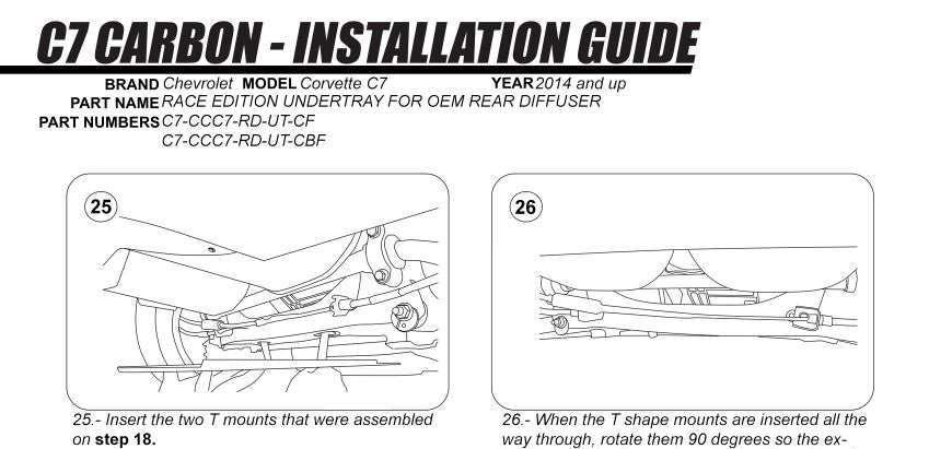
9 This is the finished Undertray install. However, the front edge is the lowest point in the rear underside! Lower than the diffuser. The TEE does not hold the undertray it floats in the hollow C7 rear crossmember. One of plastic TEEs broke and while I waited for C7 to ship a new design (which they did-see pic insert, it s metal, much better IMO.) I had an idea for a fix! I could thread the center of an aluminum bar the same size as the top of the supplied TEE. Then use a bolt with washer to pull and hold the Undertray tightly to the hollow C7 crossmember. The bar would be inserted like the TEE with it parallel to the crossmember and slipped into the crossmember hole. Then it would be rotated 90 degrees to hold in the Undertray. The only question-how TO HOLD THE BAR SO IT DID NOT TURN AS THE BOLT WAS TIGHTENED? An answer is to make two finger-hold holes in the Undertray near the bar! Not a solution C7 Carbon would use but good enough for me! Drilled two finger-hold holes next to each bolt, using a 1¼ inch hole saw. The Undertray is made of fiberglass and drills easily. The holes are to the outside of the bolts as that is where the C7 hollow crossmember holes are located. As the plastic TEE is used, the bolt is placed through the Undertray (with a washer and lock washer) into the aluminum bar on the top side. Before tightening the bolt, the bar is positioned parallel to the crossmember and inserted in holes in the hollow crossmember. Then the bar is rotated 90 degrees to clamp the front of the Undertray. Copyright by WA Technology, LLC GUttrachi@aol.com Page 9


10 Undertray Installed: Treaded the bolts and washers through the Undertray and turned both bars parallel to the C7 hollow crossmember to insert. Then turned both 90 degrees and held the bar with my finger as the bolt was tightened. Once it contacts the inside of the crossmember, friction also helps stop it from turning. The rear 5 bolts were tightened then the front two. The Undertray bent slightly to the shape of the crossmember and is held tightly to it. Interesting Observation: Viewing the pic right, shows why C7 Diffuser can fit the narrow fender Base/Z51 as well as the wider fender Grand Sport/Z06. Pic shows that is possible because the three inner screws are in the same location for both narrow and fat fenders! In my Z51 the inner screw held the splash guards. It Fits Well with the C7 Rear and Finish is Great Copyright by WA Technology, LLC GUttrachi@aol.com Page 10
 the Z51 spoiler provides no downforce, it just counters lift.")


11 Appendix: Aerodynamics General, Followed By Specifics Note the base C7 still has lift (a positive 0.20 coefficient,) the Z51 spoiler provides no downforce, it just counters lift. The Stage 2 aero Z06 provides rear downforce, Stage 3 even more but both adding significant drag! The base C7 was designed with many optimized aerodynamic elements. But more can be done! The rear spoiler on the Z51, for example, decreases lift at speed but adds drag. It also reduces the slight vacuum formed behind the car. Tadge provided this drag and lift information in a 2016 post. He also stated; We have strict criteria for pitch moment. The ratio needs to be held within a fairly narrow range so that the vehicle handling remains consistent. Too much down force on the rear and the car will understeer at higher speeds. Too much on the front and the car will oversteer. We tune all our cars to maintain neutral handling biased slightly towards understeer. A rear diffuser can add downforce with minimum extra drag. Aerodynamics is not intuitive, even the Wright Brothers measured lift on various models in a home-built wind tunnel. Of interest, the shape they developed for the propellers for best performance is optimum even today! In his 1923 race car, Bugatti knew at speed there was a partial vacuum formed in the rear of a flat rear shaped car so he used the tapered shape shown. This Porsche used a long tail approach to reduce drag. Copyright by WA Technology, LLC GUttrachi@aol.com Page 11


12 In addition to providing downforce, a small rear spoiler decreases the lowpressure area directly behind the car. This Ferrari 1960 Superamerica employs a small rear spoiler than allows a sharp cut off rear body shape. A personal example occurred as I was stopped waiting to enter a 4-lane highway! An 18-wheeler cab was traveling about 60 mph on a light rainy day. The rain and light created visible air streams. The turbulence directly behind the cab was obvious. You could visualize the partial vacuum being formed. That pressure difference was pulling on the cab causing a drag force. Recall in a fluid dynamics class the Prof showed the Teardrop Spotlights used In The Day had more drag with the bullet shape facing forward! The low pressure behind the flat surface pulls it back. Air forms a bubble in the front on the forward flat surface. On high humidity days you can see the vortices form at the ends of the wing in a race car. As the low pressure under the wing increases to atmospheric pressure, the gaseous water vapor becomes visible. Like in a cloud! MY EXPERIENCE WITH LIFT: My 260Z was known to have considerable lift at speed. The standard car produced about 140 lbs. of lift in the front and 35 lbs. in the rear at 70 mph. That was a lot for a 2700 lb. car. At 100 mph you could feel the front end become light and stability was inferior to that at normal highway speeds. Copyright by WA Technology, LLC GUttrachi@aol.com Page 12


13 The balance between front and rear downforce must be considered. I added a large front air dam and a rear spoiler like those shown left. The front was advertised as adding 100 lbs. of downforce and the rear 35 lbs at 100 mph. It was very stable at even 120 mph! Then I hit the air dam on a curb! It cracked so I took it off. While I waited for a new one to arrive, have it painted, then found time to install, the stability even at 70 mph was definitely worse! The spoiler adding downforce in the rear made the situation worse that even stock! Front and Rear Downforce Balance When adding downforce, you must consider how the balance affects handling. Excess on one end or the other can cause understeer or oversteer. Tadge said regarding the Z06, The center air dam was not used because it increased downforce excessively and resulted in Oversteer at high speeds when they require slight Understeer! Perhaps with the increased downforce, with a diffuser the air dam could be added to models without one! C7 oversteer could never be like the Corvair!! CORVAIR OVERSTEER: My first new car was a 1967 Corvair ordered with every HD option offered; quick steering, HD suspension, etc. Like the pic left I added aluminum 14-inch wheels and low profile Continental 714 tires. Great car. It was my 2 nd Corvair and I was very familiar with high speed oversteer! UNDERSTEER: Had a front wheel drive Dodge Colt Turbo in the 1980 s when we were only allowed to get gas every other day! It was a great fun car once I installed 14-inch aluminum wheels and Pirelli P7s! As it was called by the car mags, it was a Pocket Rocket! But like all front wheel drive cars it had significant understeer. Copyright by WA Technology, LLC GUttrachi@aol.com Page 13


 The center handle brake was an excellent tool to steer the car in turns! For racing, just remove the locking button.")
14 That 2200-pound front drive Colt was fun to drive if the understeer was understood and managed. The NASCAR word plowing sure fit this model. Being my first front drive car, I wasn t used to turning the wheel, hitting the gas coming out of a turn and having the car trying to go off the road, front first! Found I could use a form of trail braking to get the car pointed in the direction I wanted to go! Used the emergency brake with the button held in to reduce the side traction of the rear tires! The car rotated around! Modified S10, every HD option, Bed Cover, many mods These are information that quantifies the amount of extra drag as measured by mpg with the tailgate up versus down. The graph left shows a 2% mpg advantage being up and a 7% mpg advantage with my full bed cover. Adam and Jamie, hosts of the TV show MYTH BUSTERS, drove two identical Ford F150 pickup trucks filled with identical amounts of gas. One with the tailgate up the other down. They drove the same road and after 500 miles the one with the tailgate up went 30 miles further before it ran out of gas! That's 6% better (30/500!) The center handle brake was an excellent tool to steer the car in turns! For racing, just remove the locking button. Fun Aero Discussions: One area I had fun discussing aero was my pick-up truck and how leaving the tailgate down was decreasing mpg! All documentation says it is worse! There is a bubble of air in the bed makes air move over the area and reduce drag. With the tailgate down there is a larger are of low pressure behind the cab increasing drag! COMPUTATIONAL AERODYNAMICS Tadge said in a forum post about C7 aerodynamics, computer programs can give answers very close to the much more expensive wind tunnel tests! These programs are getting very sophisticated and can match very expensive moving floor wind tunnel data. Copyright by WA Technology, LLC GUttrachi@aol.com Page 14
 but can increase to an inch or more toward the rear of a car.")


15 Boundary Layer The layer of air next to a moving body is moving at the same speed as the body. Further from the surface, the velocity progressively changes to the surrounding velocity. Pic right is form Reference 1. It shows the air moving at ~60 mph hugs the surface in a thin layer at the start (~ 1/16 inches) but can increase to an inch or more toward the rear of a car. A thicker boundary layer results in a more drag. This video link: JQ0wE shows the Sauber F1 team using their expensive wind tunnel for a full week. Note, their wind tunnel employs a moving steel floor! It states the teams were operating their wind tunnels 24/7 then as a cost reduction, F1 rules limited that to a number of test runs they can make. Because of the accuracy of simulated aerodynamics programs, the F1 rules also limit the amount of computer teraflops of solver time they can use to help reduce costs. A step increase in the boundary layer thickness creates a turbulent boundary layer and flow separation. Flow separation in a wing, for example, will decrease downforce. (See Coanda Effect below.) Pic left from Reference 1 shows this effect occurring on a flat plate. This turbulent area creates even more drag. However, where separation is inevitable, as in the rear of the car, it is usually better to have a turbulent area with some drag penalty than flow separation that reduces downforce! There are ways to induce turbulence where desirable such as small vortex generators or even sandpaper! Copyright by WA Technology, LLC GUttrachi@aol.com Page 15

16 Coanda Effect Aerodynamics pioneer Henri Coanda made a very important contribution to how the aircraft wings produce lift when he discovered what is now called the Coanda Effect. A natural question is "how does the wing divert the air down?" When a moving fluid, such as air or water, comes into contact with a curved surface it will try to follow that surface. Coanda Graphic: The pressure difference across the air jet causes the jet to deviate towards the nearby surface, and then to adhere to it. If the surface is not too sharply curved, the jet can, under the right circumstances, adhere to the surface even after flowing 180 round a cylindrically curved surface, and therefore be traveling in a direction opposite to its initial direction. The forces that cause these changes in the direction of flow of the jet cause an equal and opposite force on the surface along which the jet flows. These Coandă effect induced forces can be harnessed to cause lift and other forms of motion, depending on the orientation of the jet and the surface to which the jet adheres This phenomenon explains why a wing (airplane or inverted race car) stops being effective it the angle of attack is too steep. To get around air stream separation problem in Formula 1, and increase the Coanda effect on wings, dual or more element or slot-gap wings are used, these allow for some of the highpressure flow from the upper surface of the wing to bleed to the lower surface of the next flap energizing the flow. This increases the speed of the flow under the wing, increasing downforce and reducing the boundary flow separation. Copyright by WA Technology, LLC GUttrachi@aol.com Page 16


17 Blown Diffuser An interesting approach was use in F1 as rules reduced that allowable configuration of diffusers. A blown diffuser is basically a way of using the exhaust gases to add to the diffuser airflow. There are two main purposes for this; 1. To try to move the wake from the rear wheels outwards where it will cause less disturbance 2. To re-energize the low-pressure air at the back of the diffuser to create more rear downforce. Does the C7 exhaust position add to the diffuser rear downforce? Don t know how much but appears it should! Graphic from C7 Carbon website. Copyright by WA Technology, LLC GUttrachi@aol.com Page 17
18 Summary: There Are Number Of Devices That Increase Downforce: A Rear Spoiler Increases Downforce But Also Significantly Increases Drag. For example, the larger spoiler on a Stage 3 Z06 provides an increased downforce coefficient of from 0 for the base Z06 with its smaller spoiler. However, it is also responsible for the majority of the drag increase that goes from a coefficient of 0.37 to 0.50 = a 35% increase! A Rear Diffuser Increases Downforce With Minimum Increase in Drag. Reference 1: Race Car Aerodynamics: by J Katz PhD:306 pages; Bentley Publishing 2006 Reference 2: Internet source by W. Toet, 12/2015: Also 4/ Copyright by WA Technology, LLC GUttrachi@aol.com Page 18
19 Note: Fits Base, Z51, Grand Sport & Z06 Item D Item T Item UT Diffuser with fins/fences: Item D Flat Plate (Item UT) Item T; Supports rear Item of Item UT Both metal and 1 7/8 inch Black Washers
20
21

22

23
24
25
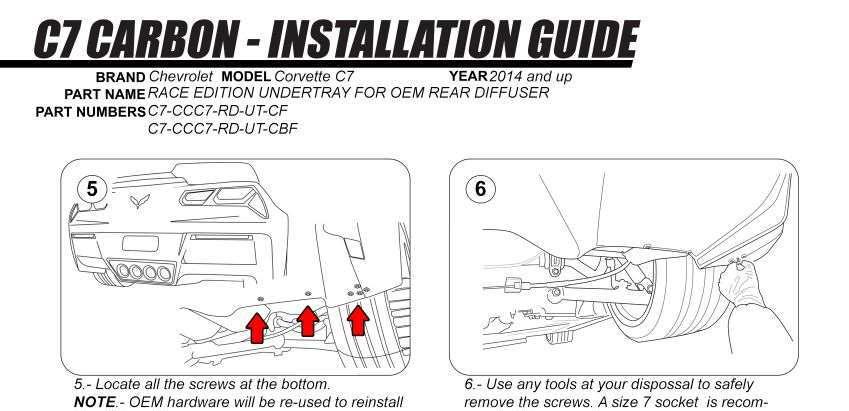
26 WA Technology HELPFUL INFORMATION ALSO WORTH REVIEWING The following Instructions/ pics are from Pilotsdiscreation, a Stingrayforum, member who posted the procedure/pics on the forum: [NOTE: This is for installing a carbon fiber OEM type diffuser so it is only related to that activity. Some items on reinstalling don t fit and most were removed.] -stingray-zo6-same.html Here's How to Change the Diffuser - should take about 45 minutes, no need to jack or lift the car, and I did all by myself without the aid of an assistant and with no special trim tools: Step 1: Start by removing the license plate Step 2: Remove the 10 lower bolts underneath the diffuser that I highlighted in the red box below:


27 Step 3: Remove the two bolts located behind the rear license plate. These are located where the blue circles are below (can't see the bolt heads here, but simple to remove):
28 Here's where the fun starts! This would be very simple if not for the fact that each horizontal reflector has two bolts behind it. This is why I think others recommend removing the entire façade, but it's not necessary due to the next steps... Step 5: Remove the vertical side vents, aka 'rear facia center grille'. The trick here is to start at the bottom outside, between the edge of the vent and the body color paint... simply pull fairly hard and it will pop right out. There are three tabs on each side, pull the three outside ones off, and leave the inside ones for later after the diffuser is all the way off:
29 Step 6: Now the bottom and sides of the diffuser should be loose, but it is still firmly held on top. To remove the horizontal reflectors firmly pull the plastic diffuser from the bottom side and slide your arm up to the back of the reflector. Use afinger to poke the back side of the and it will simply pop out!

30 This exposes two bolts per side, circled in blue below. Remove those bolts each side. Blue Circles


31 My Note: I found from text and video these two clips hard to understand. Easier than words indicate! I used a thin trim tool to open the gap from the top diffuser to the rear upper bumper. Then I used a 1 inch wide stiff paint scraper to push down the tab circled in yellow. Pull on the OEM diffuser and it will pop out. Only two such clips on each side.

32 Now the diffuser is hanging from some tabs on the top. Step 7: Pull the diffuser gently off, and set onto something soft that will protect it. 7c: Remove the side grills completely and install the 3 inside tabs onto the new diffuser. Step 8: INSTALL Carefully hang the new diffuser by inserting the top two tabs in there respective mating parts. Step 9: Reinstall the upper bolts making sure that the part is received correctly by the upper façade. You may need to apply up force to close the gap while tightening the upper bolts in order to ensure a tight fit.


33 W A Technology Grand Sport & 2014 Stingray PDF s Available: Some 45 items discuss improvements or information about a 2017 Grand Sport and 2014 Stingray function and/or esthetics. Some are minor and others, like the installing ceramic brake pads, include detailed install information. Below are the PDF s available. Click on picture (may need Ctrl pressed.) Or just copy and paste the PDF info (Blue type) into your browser. Or me at GUttrachi@aol.com and state the title desired, shown in Yellow: Note: A GS in the title indicates the info was updated from that available for the C7 Z51 PDFs. Rusty GS/C7 Muffler Why the C7 muffler is rusted and a simply way to make rust turn matte black. Bottom pic rusted, top pic treated Change GS/C7 Oil WHY change your own oil and HOW to do it Revised, includes C7 Lifting Methods C7 Carbon Fiber Side Skirts How to install side skirts with jacking information for DIY's without lifts C7 Carbon Fiber Splitter w/end Plates How to install Splitter & Nylon bra fit C7 Removing GM Plastic Film How To Remove The Rocker Panel Film Copyright by WA Technology, LLC GUttrachi@aol.com
34 GS/C7 Mirror Proximity Alarm Limit switch alarm warns when passenger mirror is too close to door frame Jacking Pads for GS/C7 Manual says Jacking Pads 2 1/2 inch max OD.. Have 1 inch, 2 inch pads semi-permanent pads. GS/C7 Radar Power For C7 tapped rear fuse panel. For GS tapped mirror GS/C7 Belt Rattle Passenger seat belt rattles against the seat back. The solution, add a shoulder belt pad. Aluminum C7 Chassis and Weld Repair The C7 has an all aluminum chassis, made from 117 welded pieces. Includes weld repair info. GS/C7Ceramic Brake Pads The Z51 has very dusty brakes. These pads help! GS/C7 License Plate Frame; Must Meet South Carolina Law Manage GS/C7 Spilled Gas & Door Lock Protect the side of the Vette when filling up with gas. Includes info on preventing door lock failure. GS/C7 License Plate & Cargo Lights LED license plate light & cargo area bulbs are brighter and whiter GS/C7 Rear Cargo Area Rear cargo area needs storage device and rear protector GS Rear Diffuser (Fits Any C7) Rear Carbon Flash Composite Diffuser Copyright by WA Technology, LLC GUttrachi@aol.com

35 GS/C7 Door Panel Protector Black plastic protector added to prevent scuffing of door when exiting GS/C7 Improved Cup Holder A solution to the cup holder spilling under hard braking or shape turns. GS/C7 Wheel Chatter/Hop Why sharp, low speed turns with cold tires causes the front tires to chatter/hop. C7 Carbon Fiber Grille Bar Install genuine carbon fiber grille bar overlay Jacking a GS/C7 Vette Safely jacking either front only or back & front Deer Whistle Installed on GS/C7 Do they work? Plus Install Info Replacing C7 Battery After using a GM type charger and showing fully charged a voltage low, replaced battery with AGM! GS/C7 Window Valet Lower Windows with FOB Window Valet Helps 2014/2015 Latch Hatch GS/C7 Splash Guards GM offers splash guards for the C7 Corvette. An easy DIY installation. ACS Best Front Guards for GS. GS/C7 Blind Spot Mirror Smaller rear and side windows cause C7 blind spots. Small "blind spot mirrors" help Copyright by WA Technology, LLC GUttrachi@aol.com


36 GS/C7 Skid Pad Protector After the air dam, the aluminum "skid pad" hits driveway ramps etc. Plastic protector helps. GS/C7 Wheel Locks Wheel locks, torqued to required 100 ft-lbs, help protect your expensive wheels from theft. GS/C7 OnStar Lights The OnStar LED's in the rear view mirror, at a quick glance, look like a police car flashing light! This is a fix. GS/C7 Skip Shift Eliminator Skip Shift Eliminator install with suggestions on jacking a C7. GS/C7 Catch Can & Clean Oil Separator Direct inject engines like the LT1, are particularly subject to coking. What is Coking and how to reduce the potential? GS/C7 Round Shift Knob A round shift knob shortens throw. GS/C7 Stingray Sill Plate Stingray sill plate replaces original. GS/C7 Nylon Bra Nylon Bra Stops Bugs on Front and Grill. Fits with Stage 3 Winglets GS/C7 Clutch Fluid Change Clutch fluid after 3000 miles gets dirty C7 Carbon Fiber Hood Vent Replaces Plastic Hood Vent Copyright by WA Technology, LLC GUttrachi@aol.com
37 GS/C7 Cold Air Intake Low Restriction Air Filter & Duct Garmin GPS for GS Cubby Garmin Mounts in GS Cubby & Apple CARPLAY GS Splitter Stage 3 Winglet Stage 3 Winglets Integrate with Spats GS 2LT to 2.5 LT Red Upper Dash Pad Like 3LT Jake Emblem/Decals for GS Jake Symbols Support GS Racing Image GS Splitter Protector Scrape Armor Protection for Splitter GS Engine Compartment Mods Cosmetic Additions in Engine Compartment GS Vitesse Throttle Controller: Fits All C7s Adjustable Throttle-by-Wire Control Boomy Bass Solution Use Presets to Adjust Bass etc Tone/Balance GS Air Dam, Functions Why Missing from Z51, Some GS & Z06 Engineering a ProStreet Rod How Our 34 ProStreet Rod Was Designed and Built od% pdf Motorsports Welding Article Wrote a 5 Page Article for AWS March 2018 Journal Covers NHRA and NASCAR Chassis Design Copyright by WA Technology, LLC GUttrachi@aol.com
Maybe Splash Guards Will Solve the Protection Need
 W A Technology GM Plastic Rocker Panel Film Removal sticky tires, especially when they are hot. It s difficult to see from pictures how very noticeable the plastic protectors are that GM installed on the
W A Technology. Powering A Radar Detector Install Grand Sport. You re a Target: Installing a Detector: Powering the Passport Max:
 W A Technology Powering A Radar Detector Install Grand Sport A Radar Detector is a necessity if you own a Corvette! Even if you stay within 8 miles per hour of the speed limit, not easy, there will be
Getting The Hatch to Latch in C7; Comment on Grand Sport Memory Wire Activated Hatch Vent
 W A Technology Getting The Hatch to Latch in C7; Comment on Grand Sport Memory Wire Activated Hatch Vent Where my 2008 C6 had a motorized pull down motor to latch the hatch, GM made a very big deal of
Drag Race Roll Bar (MMRB-6, -7)
") 3430 Sacramento Dr., Unit D San Luis Obispo, CA 93401 Telephone: 805/544-8748 Fax: 805/544-8645 www.maximummotorsports.com 1994-04 Drag Race Roll Bar (MMRB-6, -7) The Maximum Motorsports 6-point Drag Race
3430 Sacramento Dr., Unit D San Luis Obispo, CA 93401 Telephone: 805/544-8748 Fax: 805/544-8645 www.maximummotorsports.com 1994-04 Drag Race Roll Bar (MMRB-6, -7) The Maximum Motorsports 6-point Drag Race
Roll Bar (MMRB-6.1 to -6.7)
") 3430 Sacramento Dr., Unit D San Luis Obispo, CA 93401 Telephone: 805/544-8748 Fax: 805/544-8645 www.maximummotorsports.com 1994-04 Roll Bar (MMRB-6.1 to -6.7) NOTE: These instructions cover Roll Bars with
3430 Sacramento Dr., Unit D San Luis Obispo, CA 93401 Telephone: 805/544-8748 Fax: 805/544-8645 www.maximummotorsports.com 1994-04 Roll Bar (MMRB-6.1 to -6.7) NOTE: These instructions cover Roll Bars with
LPE C5 Battery Relocation Kit
 LPE C5 Battery Relocation Kit The LPE C5 Corvette battery relocation kit improves vehicle weight distribution by moving weight to the rear of the vehicle. The improved weight distribution increases traction
IMPORTANT: PLEASE RETAIN THIS INSTRUCTION MANUAL FOR FUTURE REFERENCE
 IMPORTANT: PLEASE RETAIN THIS INSTRUCTION MANUAL FOR FUTURE REFERENCE 2009 Toyota RAV-4 Stainless Steel Mesh Grilles L 30 G8P Fine Mesh Part #30-002-09 Quantity Description Part No. Upper Mesh Grille (includes):
COLD AIR INTAKE INSTALLATION INSTRUCTIONS
 COLD AIR INTAKE INSTALLATION INSTRUCTIONS # D760-0030 Fits: 2007-10 135i (E82, E88; with N54 engine) 2007-08 335i/xi (E90) 2007-10 335i (E92, E93; with N54 engine) Congratulations for being selective enough
Fig A ADDICTIVE DESERT DESIGNS. Preparation: Removal:
 Preparation: Disconnect the negative battery terminal. Park the vehicle on level ground and set the emergency brake. We recommend reading through the installation instructions in whole before performing
Steeda Sport Mustang Lowering Springs (2005+) - Installation Instructions
 - Installation Instructions") Steeda Sport Mustang Lowering Springs (2005+) - Installation Instructions The below installation instructions work for the following products: Steeda Sport Mustang Lowering Springs (2005+) Please read
Steeda Sport Mustang Lowering Springs (2005+) - Installation Instructions The below installation instructions work for the following products: Steeda Sport Mustang Lowering Springs (2005+) Please read
Installation Instructions and Suggestions For Jeep YJ Fiberglass Replacement Bodies
 Installation Instructions and Suggestions For Jeep YJ Fiberglass Replacement Bodies Getting started with the removal of your existing Jeep body. Trust nothing to memory; take photos of everything at different
RS-2 SINGLE ACTION REAR BUMPER WITH TIRE CARRIER INSTALL MANUAL FOR JEEP WRANGLER ALL MODELS.
 RS-2 SINGLE ACTION REAR BUMPER WITH TIRE CARRIER INSTALL MANUAL FOR 2007-2016 JEEP WRANGLER ALL MODELS. Rear Bumper Installation Instructions 1) Remove factory rear bumper, (this includes all tow hitch
PLEASE READ CAREFULLY AND COMPLETELY BEFORE BEGINNING THIS INSTALLATION, you will find many helpful hints in the instructions.
 PLEASE READ CAREFULLY AND COMPLETELY BEFORE BEGINNING THIS INSTALLATION, you will find many helpful hints in the instructions. IF YOU ARE UNCOMFORTABLE WITH ANY ASPECT OF THIS INSTALLATION PLEASE REFER
850 M-Technic Body Parts (CSi)
") 850 M-Technic Body Parts (CSi) Part Description BMW Part No. Qty List Price Front Spoiler 51-11-2-253-000 1 $ Rear Valance 51-12-2-253-005 1 $ Installation Kit 82 11 9 402 709 1 $ Flap Cover for Rear
850 M-Technic Body Parts (CSi) Part Description BMW Part No. Qty List Price Front Spoiler 51-11-2-253-000 1 $ Rear Valance 51-12-2-253-005 1 $ Installation Kit 82 11 9 402 709 1 $ Flap Cover for Rear
STEPS FOR REMOVING REAR ASHTRAY & CUP HOLDER, CENTER ARMREST, E- BRAKE CONSOLE, FRONT ASHTRAY, LOWER CENTER CONSOLE AND GLOVE BOX
 Please give credit where credit is due! This DIY was completed ENTIRELY by the hardest working VW Vortex moderator on the site!! Gary Thompson, Ph.D. - vortex ID VGRT6, email address vgrt6@yahoo.com. Please
Replacing MK4 Golf/Jetta radiator mounts in-car
 Replacing MK4 Golf/Jetta radiator mounts in-car This is a guide to replacing the radiator mounts in a MK4 Golf/Jetta. This involves moving the core support to the service position which allows you to do
Bag 1. Bag 1. Center Pivot. Center Pivot
 8 00734 01901 5 Center Pivot Bag 1 3374 - Center Pivot Socket 4019 - Alum Pivot ball 3254-2-56 Button Head *Note - Sometimes it is helpful to slightly over-tighten the top clamp screws, then work the ball
Two bolts at. Two each side where studs pass through. rear. Two bolts at. front. Front-most bolt for diagonal brace. Rear jacking point
 The following describes the process of changing the transmission s gear oil in my own 2008 CS 6sp. I have no relationship with any of the products mentioned, other than being a satisfied consumer. Exercise
The H-MAC Heavy Metal Articulating Chassis Construction Guide
 The H-MAC Heavy Metal Articulating Chassis Construction Guide The Heavy Metal Chassis is constructed with two identical drive modules built using 10 mechanical sub-assemblies. The drive modules are integrated
Connecting the rear fog light on the A4 Jetta, while keeping the 5 Light Mod
 Connecting the rear fog light on the A4 Jetta, while keeping the 5 Light Mod DISCLAIMER: I'm human and make mistakes. If you spot one in this how to, tell me and I'll fix it This was done on my 99.5 Jetta.
05-08 GT. Hellion Power Systems Mustang Kit Instructions
 Hellion Power Systems 05-08 Mustang Kit Instructions 1. Disconnect Battery 2. Drain Radiator, keep fluid for re-installation. 3. Remove air box and inlethoses. 6. Next, underneath, punch oil pan for turbo
1964 1/2-70 Mustang Torque Arm Rear Suspension Installation Instructions
 1964 1/2-70 Mustang Torque Arm Rear Suspension Installation Instructions 1-800-984-6259 www.totalcostinvolved.com Version 2 (c) 2008 Total Cost Involved Engineering, Inc. All Rights Reserved. Page 1 of
Subaru Front Mount Intercooler Kit STI Subaru Front Mount Intercooler Kit STI
 Subaru Front Mount Intercooler Kit STI 2008-2014 715500 Subaru Front Mount Intercooler Kit STI 2008-2014 Congratulations on your purchase of the Subaru Front Mount Intercooler Kit STI 2008-2014. The following
Mustang CDC Lightbar (94-04) - Installation Instructions
 - Installation Instructions") Mustang CDC Lightbar (94-04) - Installation Instructions The below installation instructions work for the following products: Classic Design Concepts Mustang Convertible Lightbar (94-04 Carbon Fiber) Classic
Mustang CDC Lightbar (94-04) - Installation Instructions The below installation instructions work for the following products: Classic Design Concepts Mustang Convertible Lightbar (94-04 Carbon Fiber) Classic
DrVanos.com Stage II Installation Instructions. Tool rental is available with the purchase of a vanos kit *See website for more info*
 DrVanos.com Stage II Installation Instructions Special Tools Needed: Camshaft locking tool TDC Crank pin Sprocket turning tool Tool rental is available with the purchase of a vanos kit *See website for
Installation Instructions
 Installation Instructions Jeep JK 2-Door (2011 Present) Mounting Bracket and Air Line System Kit for ARB On-Board Twin Air Compressor (CKMTA12) Made in the USA Kit Contents: 1 Flat Bracket 1 Formed Bracket
INSTALLATION INSTRUCTIONS
 COLD AIR INTAKE INSTALLATION INSTRUCTIONS PART NUMBER D760-0390C APPLICATION: 1999-2003 E39 M5 PARTS LIST 1 Left Aluminum Intake Tube 1 Air Pump Bracket (A) 1 Right Aluminum Intake Tube 1 Air Pump Bracket
Please try our way first.
 1958-1962 Corvette Raingear installation instructions Designer s Note: The 1958-1962 Corvette RainGear wiper system that you have purchased is complex and will require patient fitting. Complete Instructions
Steeda S550 MT-82 Tri-Ax Race Short Throw Shifter Installation Instructions For Parts: ,
 Steeda S550 MT-82 Tri-Ax Race Short Throw Shifter Installation Instructions For Parts: 555-7317, 555-7318 Tools required 1. 7mm socket 2. 10mm socket 3. 13mm socket 4. 15mm socket 5. 18mm socket 6. 3/8
GENUINE PARTS INSTALLATION INSTRUCTIONS
 GENUINE PARTS INSTALLATION INSTRUCTIONS DESCRIPTION: APPLICATION: PART NUMBER: KIT-CARBON FIBER REAR SPOILER INFINITI Q50 T99J1 J5000 KIT CONTENTS: Item A B C D Qty. 1 4 1 1 Part Description Spoiler Assembly
COLD AIR INTAKE INSTALLATION INSTRUCTIONS. # D Fits: F10 M5 # D Fits: F06/F12/F13 M6 PARTS LIST
 COLD AIR INTAKE INSTALLATION INSTRUCTIONS # D760-0035 Fits: 2013-15 F10 M5 # D760-0037 Fits: 2012-15 F06/F12/F13 M6 PARTS LIST (1) Left Carbon Airbox Lid (1) Right Carbon Airbox Lid (1) Left Carbon Snorkel
HURST COMP STICK KIT 2008 and up DODGE CHALLENGER (with AUTO-STICK) Catalog # &
 Catalog # &") FORM 159 0402 03/09 HURST COMP STICK KIT 2008 and up DODGE CHALLENGER (with AUTO-STICK) Catalog #538 0402 & 538 0403 2009 by Hurst Perfomance Thank you for purchasing the Hurst Comp Stick Kit for your
FORM 159 0402 03/09 HURST COMP STICK KIT 2008 and up DODGE CHALLENGER (with AUTO-STICK) Catalog #538 0402 & 538 0403 2009 by Hurst Perfomance Thank you for purchasing the Hurst Comp Stick Kit for your
DODGE SuperRail Mounting Kit #0848
 DODGE SuperRail Mounting Kit #0848 #1200 Super 5 th (16K) #0800 Super 5 th (20.5K) Gross Trailer Weight (Maximum) Vertical Load Weight (Max. Pin Weight) 16,000 lbs. 4,000 lbs. Gross Trailer Weight (Maximum)
AMERICAN CAR CRAFT INSTRUCTIONS
 AMERICAN CAR CRAFT INSTRUCTIONS C7 CORVETTE STINGRAY 4pc Mud Guards CARBON FIBER WRAPPED PART #052024 PARTS INCLUDED 4- stainless mud guard s w/carbon fiber wrap protection for the inner wheel well 2-
Stand Alone Fog Lights Installation Instructions
 Tools Required: 1. Trim Removal tool or protected flat screwdriver 2. #2 Phillips Screwdriver 3. 10mm socket 4. 10mm wrench 5. 8mm or 5/16 socket 6. Adjustable Pliers 7. Electrical Tape WARNING!!! Disconnect
Disco 3 Clock Spring / Rotary Coupler replacement
 Disco 3 Clock Spring / Rotary Coupler replacement I recently had to change my Clock spring and thought some folks may find it helpful to see what it entailed. I did lots of reading around but couldn t
2015 Copyright Maxspeed-Motorsports.com
 1 Porsche PCM 3.1 Backup Camera Installation Instructions. Thank you for purchasing your product at www.maxspeedmotorsports.com Before you start please understand that these installation instructions are
Mustang Radiator Conversion DIY. By GearHeadPeter. January 27, 2011
 1964-1966 Mustang Radiator Conversion DIY By GearHeadPeter January 27, 2011 We all know that the radiators in our cars are not the best, especially if you have done any customization to the engine, which
INSTALLATION INSTRUCTIONS Part# , , ,
 INSTALLATION INSTRUCTIONS Part# 20-0218, 22-0318, 20-0118, 22-0219 20-0218 - 4 Tire On Board Air Delivery System and Dual Compressed Air System Includes ARB CKMTA12 Compressor 20-0118 - 2017 FORD RAPTOR
COLD AIR INTAKE INSTALLATION INSTRUCTIONS
 COLD AIR INTAKE INSTALLATION INSTRUCTIONS # D760-0029 Fits: 2009-10 335i/xi (E90; with N54 engine) Congratulations for being selective enough to use a Dinan Engineering Cold Air Intake. We have spent many
Genuine Corvette Accessories Carbon Fiber Radio Surround Installation Instructions for Corvettes.
 Genuine Corvette Accessories Carbon Fiber Radio Surround Installation Instructions for 2005-2007 Corvettes. Difficulty: 3 out of 5. Time: Plan on about 1 hour. The tools used are: A small flashlight A
INSTALLATION / OPERATING INSTRUCTIONS Reese Elite Series FIFTH WHEEL SLIDER HITCH
 INSTALLATION / OPERATING INSTRUCTIONS Reese Elite Series FIFTH WHEEL SLIDER HITCH DEALER/INSTALLER: (1) Provide this Manual to end user. (2) Physically demonstrate hitching and unhitching procedures in
Door panel removal F07 5 GT
 Things needed Decent plastic trim removal tools Torx 30 Spare door clips 07147145753 I got away with a set of 5 but if I did it again I d be cautious and get 10. From prior experience if they are damaged
Depress each tab as you pull the bezel off. The bezels are tight. L.H. shown.
 2013-2014 Ford Mustang V6 & Boss 302 Lower Valance Fog Light Kit Parts List: Quantity: Tool List: Fog light & bulb with bracket 2 Flat head & Phillips screwdriver Black bezels 2 Ratchet & Socket set OR
AMT Motorsport C7 Corvette Camber Kit User s Guide. 8 Upper Control Arm Studs and hardware for rear upper control arm adjustments
 AMT Motorsport C7 Corvette Camber Kit User s Guide Thank you for purchasing the AMT Motorsport Camber Kit for the C7 Corvette. We believe this is the most versatile camber kit available on the market,
Turbinator-2 Build Manual
 Turbinator-2 Build Manual Thank you for your purchase of the Turbinator-2 sport jet by Boomerang RC Jets. This RC Jet IS NOT A TOY and should only be flown and operated by experienced RC Turbine Pilots.
4.2 Friction. Some causes of friction
 4.2 Friction Friction is a force that resists motion. Friction is found everywhere in our world. You feel the effects of when you swim, ride in a car, walk, and even when you sit in a chair. Friction can
2005+ Roll Bar (Mm5RB-20.1 to -20.6) Recommended Center punch 1/8" pilot drill 1-3/4" Hole saw 2" Hole saw
 Recommended Center punch 1/8 pilot drill 1-3/4 Hole saw 2 Hole saw") 3430 Sacramento Dr., Unit D San Luis Obispo, CA 93401 Telephone: 805/544-8748 Fax: 805/544-8645 www.maximummotorsports.com 2005+ Roll Bar (Mm5RB-20.1 to -20.6) Recommended Center punch 1/8" pilot drill
3430 Sacramento Dr., Unit D San Luis Obispo, CA 93401 Telephone: 805/544-8748 Fax: 805/544-8645 www.maximummotorsports.com 2005+ Roll Bar (Mm5RB-20.1 to -20.6) Recommended Center punch 1/8" pilot drill
INSTALLATION INSTRUCTIONS
 Rear Vision System Aftermarket and Factory 5.0, 8.4 and 6.1 MyGig Touch Screen Display (Factory Display requires Chrysler/Dodge dealer to activate) 2009 Current* Dodge Ram (Kit part number 1009-6503) *NOTE:
1967 (Late) CORVETTE STANDARD (NON-ADJUSTABLE) STEERING COLUMN DISASSEMBLY & REPAIR INSTRUCTIONS PAPER #2
 CORVETTE STANDARD (NON-ADJUSTABLE) STEERING COLUMN DISASSEMBLY & REPAIR INSTRUCTIONS PAPER #2") Last Revision: 03SE2012 1967 (Late) - 1968 CORVETTE STANDARD (NON-ADJUSTABLE) STEERING COLUMN DISASSEMBLY & REPAIR INSTRUCTIONS PAPER #2 Disassembly and Repair Instructions Addressed in this Paper Degree
Last Revision: 03SE2012 1967 (Late) - 1968 CORVETTE STANDARD (NON-ADJUSTABLE) STEERING COLUMN DISASSEMBLY & REPAIR INSTRUCTIONS PAPER #2 Disassembly and Repair Instructions Addressed in this Paper Degree
INSTALLATION INSTRUCTIONS
 INSTALLATION INSTRUCTIONS [1] Description: Tow Hitch Wire Harness Kit [2] Application: Nissan Rogue Note: Tow Harness application is limited to specific vehicle option packages that include tow harness
Flow Visualization Tunnel. Owner s Manual. May 2009
 Flow Visualization Tunnel May 2009 AEROLAB LLC 2009 Contents Introduction... 3 Description... 3 Warnings / Precautions... 4 Tunnel Overview... 5 Main Control Panel... 6 Basic Operation... 8 Auxiliary Blower
Remove the 3-11mm nuts holding mirror on. Don t drop the nuts!
 2005-2012 Ford Mustang Puddle Lamp Kit Parts List: Quantity: Tool List: LED Lamps 2 Flat head screwdriver Seals 2 Ratchet & Socket set OR Nuts 2 Adjustable Wrench Wiring harness 1 Drill & 11/16 th bit
OEM Cruise Control Installation in GMC/Chevy NBS trucks
 OEM Cruise Control Installation in 99-02 GMC/Chevy NBS trucks May 2008 ~ Rampage_Rick Having just installed factory cruise control in my 00 Sierra, I thought I d share the fun. I followed the steps outlined
Lincoln Mark VII T5 Swap Version submitted by 5.0 bird
 Lincoln Mark VII 1984-1989 T5 Swap Version 20070611 submitted by 5.0 bird I've decided to make an article to assist with the T5 swap for the 84-89 Mark VIIs, since I was just in there because my DOA didn't
Rostra Electronic Cruise Control Install On a Stratoliner or Roadliner
 Rostra Electronic Cruise Control Install On a Stratoliner or Roadliner MATERIALS LIST: 1 - Rostra Part # 250-1223 (www.brandondist.com/products/cruise1223.htm) 1 - Signal Splitter part # 250-4369 1 - Engagement
Grille Guard PART NUMBER: WCGM B
 Grille Guard PART NUMBER: WCGM-158-21-B Fits: 2015 Chevrolet Colorado 2015 GMC Canyon 60-180 min CUTTING REQUIRED DRILLING NOT REQUIRED REMOVE CONTENTS FROM BOX. VERIFY ALL PARTS ARE PRESENT. READ INSTRUCTIONS
Land Cruiser FJ80 and FZJ80 Double Swingout Rear Bumper Installation Instructions PRELIMINARY
 Land Cruiser FJ80 and FZJ80 Double Swingout Rear Bumper Installation Instructions Fits 1991-1997 80 Series Land Cruiser / Lexus LX450 PRELIMINARY Thank you for purchasing a Rear Bumper for your Land Cruiser.
2018 4X4 TUNDRA DBL CAB LTD 5.7L Accessories
 March 22, 2018 Ontario Chrome Tailgate Insert Badge $119.50 Individual letters fit in the stamped tailgate Tundra logo Attached with strong 3M adhesive backing Two colors available: bright chrome and flat
LGT-311L Bumper LED Light Kit EZ-Go RXV Installation Instructions
 LGT-311L Bumper LED Light Kit EZ-Go RXV Installation Instructions Caution: Please read through the instructions carefully. Before starting this project, remove the system s positive and negative connections
Z1 Motorsports 350Z / G35 Oil Cooler Kit Installation Manual
 Z1 Motorsports 2877 Carrollton Villa Rica Hwy Carrollton GA 30116 770.838.7777 Z1 Motorsports 350Z / G35 Oil Cooler Kit Installation Manual For 19, 25 and 34 Row Oil Cooler Kits Parts Included: 1 Aluminum
Porsche 928 with 16v LH-Jetronic Fuel System
 Porsche 928 with 16v LH-Jetronic Fuel System Toll-Free Tech Hot Line: 877-FOR-928M 877-367-9286 Please do not copy this manual and give copies to your friends. Our ability to bring you this supercharger
INSTALLATION INSTRUCTIONS
 INSTALLATION INSTRUCTIONS BIG ROTOR / CALIPER RELOCATION FRONT KITS SUM-BK1422, BK1423, BK1424 1999-2006 GM 1/2 Ton Trucks & SUVs Thank you for choosing SUMMIT RACING for your braking needs. Pleases take
The drawings are all available from the author or from the host websight. You will find these pictures and descriptions to be most helpful.
 Last Revision: 10JA2010 1969 THRU 1976 GM A & F-CAR STANDARD (NON-ADJUSTABLE) STEERING COLUMN DISASSEMBLY & REPAIR INSTRUCTIONS PAPER #1 Disassembly and Repair Instructions Addressed in this Paper Degree
<THESE INSTRUCTIONS MUST BE GIVEN TO THE END USER> B&W Trailer Hitches 1216 Hawaii Rd / PO Box 186 Humboldt, KS P: F:
 B&W Trailer Hitches 26 Hawaii Rd / PO Box 86 Humboldt, KS 66748 P:620.473664 F:620.473766 Turnoverball Gooseneck Hitch Installation Instructions Mounting
Sunroof Repair. Sunroof Repair TSB. The sunroof repair kit available for the J30 is part number Y20. See images at bottom of document.
 Sunroof Repair This document is the text/images from the TSB (technical service bulletin) issued by Infiniti concerning the repair procedure for sunroof issues. Be advised that this is a LARGE, TIME-CONSUMING
Projector39/Umnitza BMW Headlight & Re-Installation for E39s Predator Angel Eyes, and Lamin-X Installation
 Projector39/Umnitza BMW Headlight & Re-Installation for E39s Predator Angel Eyes, and Lamin-X Installation Now it is time to remove the headlights! Obviously you have to open the hood to do this. 100_3630.jpg
INSTALLATION INSTRUCTIONS SEMI Hidden Kit Part Number: Application: Toyota Tacoma
 INSTALLATION INSTRUCTIONS SEMI Hidden Kit Part Number: 100044 Application: 2016+ Toyota Tacoma GENERAL SAFETY PRECAUTIONS Your safety, and the safety of others, is very important. To help you make informed
Fig A. Addictive Desert Designs. Preparation: Removal:
 Preparation: Disconnect the negative battery terminal. Park the vehicle on level ground and set the emergency brake. We recommend reading through the installation instructions in whole before performing
---Optional Items---
 1 2 3 4 5 6 ---Optional Items--- 10 9 11 7 8 12 This package should contain: 1. One (1) CorkSport Crashbar Weldment 2. Eight (8) M8x1.25x20 mm Bolts 3. Eight (8) M8x1.25mm Nyloc Nuts 4. Sixteen (16) M8
Installation Manual TWM Performance Short Shifter Cobalt SS/SC, SS/TC, HHR SS, Ion Redline and Saab 9-3
 Page 1 Installation Manual TWM Performance Short Shifter Cobalt SS/SC, SS/TC, HHR SS, Ion Redline and Saab 9-3 Please Note: It is preferable to park on a flat surface, as you will have to engage and disengage
2. With the rear door open remove pull-style clip from the passenger side just below the door latch.
 LoD Offroad FJ Cruiser Rear Bumper with Tire Carrier Installation Instructions 1. Begin with removing factory spare from the rear door. 2. With the rear door open remove pull-style clip from the passenger
SW20 Coolant System Maintenance.
 SW20 Coolant System Maintenance. This article contains information on how to change and bleed the coolant, as well as flushing the system. It is based on information in the service manual, tips gathered
SKID MARK GARAGE. Axillary Fuel Supply
 1 SKID MARK GARAGE Axillary Fuel Supply *Disclaimer: Our Axillary Fuel kits are designed to fit most late model GM vehicles with minimum modifications. While not quite a universal kit for all, it has been
Prusa i3 Printer Assembly Guide
 Prusa i3 Printer Assembly Guide Special thanks to Carlos Sanchez and Miguel Sanchez for the graphics. All graphics captured from their great animation: http://www.carlos-sanchez.com/ Prusa3/ For copyright
Fig A ADDICTIVE DESERT DESIGNS. Preparation: Removal: Release these clips
 Preparation: Disconnect the negative battery terminal. Park the vehicle on level ground and set the emergency brake. We recommend reading through the installation instructions in whole before performing
Current Ford F150 Race Series R Rear Bumper Installation Instructions
 2015 - Current Ford F150 Race Series R Rear Bumper Installation Instructions PREPARATION STEPS 1. Disconnect the negative terminal on the battery. Park the vehicle on level ground and set the emergency
The man with the toughest job in F1
 The man with the toughest job in F1 Tyres are the key to performance in Formula 1, and as Caterham s Head of Tyres, Peter Hewson s job is to know as much about them as possible. There s only one problem:
<THESE INSTRUCTIONS MUST BE GIVEN TO THE END USER> B&W Trailer Hitches 1216 Hawaii Rd / PO Box 186 Humboldt, KS P: F:
 B&W Trailer Hitches 26 Hawaii Rd / PO Box 86 Humboldt, KS 66748 P:620.473664 F:620.869.903 Turnoverball Gooseneck Hitch Installation Instructions Mounting
2015+ SUBARU STI FRONT-MOUNT INTERCOOLER PARTS LIST AND INSTALLATION GUIDE INSTALL DIFFICULTY DISCLAIMER CAUTION INSTALL PROCEDURE TOOLS NEEDED
 PARTS LIST AND PARTS INCLUDED 1PC ALUMINUM INTAKE PIPE 1PC BAR-AND-PLATE INTERCOOLER 1PC STEEL CRASH BAR W/ MOUNTING HARDWARE 2PC HOT-SIDE INTERCOOLER PIPES 2PC COLD-SIDE INTERCOOLER PIPES 1PC BPV FLANGE
4 pieces of silicone hose Unless you have AEM then you have 2 2.5, 1 3, and 1 3.5
 The parts in your kit: 3 pieces of Mandrel-Bent Aluminized Tubing: 1 Straight 1 45 degree bend with straight section 1 curved section 4 pieces of silicone hose 1 2.5 1 3.5 2 3 Unless you have AEM then
LiteDOT Installation Document
 LiteDOT Installation Document This document designed to aid in installation of LiteDOT s on Jeep TJ models, other models are similar. NOTE: Installing LiteDOT s on a Jeep where the 2 necessary mounting
Lingenfelter Signature Series Camaro SS Rear Valance
 Lingenfelter Signature Series 2010-2012 Camaro SS Rear Valance PN: L850161410 Lingenfelter Performance Engineering 1557 Winchester Road Decatur, IN 46733 (260) 724-2552 (260) 724-0422 fax www.lingenfelter.com
2011 Honda Accord Coupe Fine Mesh Grille
 IMPORTANT: PLEASE KEEP THIS INSTRUCTION MANUAL FOR FUTURE REFERENCE! TOOLS REQUIRED 2011 Honda Accord Coupe Fine Mesh Grille Replacement Upper / Lower Overlay Part #: Complete #1124-0102-11 / Black Ice
Factory Five Racing, Inc. 818 Kit Assembly manual revision 1J update
 Factory Five Racing, Inc. 818 Kit Assembly manual revision 1J update Turbo coolant overflow tank...1 Shifter handle...4 Install...4 Door skin...7 Door Liner... 10 Side mirrors... 14 Door handles and pulls...
INSTALLATION INSTRUCTIONS
 INSTALLATION INSTRUCTIONS Accessory REAR SPOILER Application 2011 CR-Z MUGEN Publications No. AII 45919 Issue Date APRIL 2011 PARTS LIST Right wing bracket Rear wing Left wing bracket Right wing base Right
Motions and Forces Propeller
 Motions and Forces Propeller Discovery Question What are the effects of friction on the motion of the propeller-driven cart? Introduction Thinking About the Question Materials Safety Trial I: Adding a
#TL T EA888 GEN 3 FUELING SYSTEM/ INSTALLATION INSTRUCTIONS
 #TL100069 2.0T EA888 GEN 3 FUELING SYSTEM/ INSTALLATION INSTRUCTIONS Notes: These instructions were written for a North American specification MkVII GTI. Other models, like the Golf R, are similar. When
Chevy Chevy 2500 & 3500 SuperRail Mounting Kit #3515
 1999-2007 Chevy 1500 1999-2010 Chevy 2500 & 3500 SuperRail Mounting Kit #3515 #3600 SuperGlide (24K) Gross Trailer Weight (Maximum) Vertical Load Weight (Max. Pin Weight) 24,000 lbs. 6,000 lbs. Installation
PLEASE READ THROUGH THE WHOLE WRITE UP BEFORE ACTUALLY USING IT!!!!
 JDM power folding mirror switch install into stock USDM harness. By: Greg L., Zeke21 on twinturbo.net PLEASE READ THROUGH THE WHOLE WRITE UP BEFORE ACTUALLY USING IT!!!! This is how I was able to get the
U L T I M A T E R A D A R / L A S E R D E F E N S E S Y S T E M
 S m a r t e r Q u i e t e r M o r e A c c u r a t e U L T I M A T E R A D A R / L A S E R D E F E N S E S Y S T E M Installation Manual PASSPORT 9500ci Comes Complete Front Radar Receiver Miniature weatherproof
Installation Instructions QUICKSILVER CONSOLE SHIFTER Fits: Chevelle / El Camino
 WORK SAFELY! For maximum safety, perform this installation on a clean, level surface and with the engine turned off. Place blocks or wedges in front of and behind both rear wheels to prevent movement in
Here is the gap seal I used for the flaps, genuine hardware store quality. Note cross sectional shape visible on the right end.
 HOMEBUILT AIRCRAFT DRAG REDUCTION - Case Study with a Lancair IV Part 3 Copyright - Fred Moreno - January 2009 Rev. 1 Portions may be reproduced for private, individual use 3- REDUCED AIRFRAME DRAG FOR
Sport Sway Bar Kit Mustang
 Sport Sway Bar Kit 22102 2005 Mustang Installation of Hotchkis Front Sway Bar 1F Raising Vehicle Securely block the rear wheels of the vehicle. Use a jack to lift up the front of the vehicle and use jack
INSTALLATION INSTRUCTIONS
 HIGH FLOW AIRFLOW METER INSTALLATION INSTRUCTIONS PART NUMBER D763-1600A APPLICATION: 2001-06 E46 M3 Parts List: Hose clamp 64Z (7) Plastic Rivets Air Filter Temp Sensor & Harness (2) Button Head Screws
<THESE INSTRUCTIONS MUST BE GIVEN TO THE END USER> B&W
 B&W Trailer Hitches 1216 Hawaii Rd / PO Box 186 Humboldt, KS 66748 P:620.473.3664 F:620.869.9031 Turnoverball Gooseneck Hitch Installation Instructions
Universal Mounting Kit #0820
 Universal Mounting Kit #0820 #1200 Super 5 th (16K) #0800 Super 5 th (20.5K) Gross Trailer Weight (Maximum) Vertical Load Weight (Max. Pin Weight) 16,000 lbs. 4,000 lbs. Gross Trailer Weight (Maximum)
4 th Gen 4 Runner Front Bumper - Installation Instructions:
 www.shrockworks.com info@shrockworks.com 877-474-7625 4 th Gen 4 Runner Front Bumper - Installation Instructions: Thank you for purchasing a ShrockWorks product. We are confident you will enjoy it for
Changing the Struts on a WK Jeep CRD
 Changing the Struts on a WK Jeep CRD Step by Step By Chirpz Disclaimer: I do not claim that this procedure is the right way or even the best way to change your struts. This is what I did after reading
INSTALLATION INSTRUCTIONS
 INSTALLATION INSTRUCTIONS BIG ROTOR / CALIPER RELOCATION REAR KIT SUM-BK1423 1999-2009 GM 1/2 Ton Trucks & SUVs Thank you for choosing SUMMIT RACING for your braking needs. Pleases take the time to read