CONTENTS. Special tools Technical Data. 7 Clutch, Automatic plate (120mm diameter) 8
|
|
|
- Ralph Elliott
- 5 years ago
- Views:
Transcription

1 1
2 CONTENTS Special tools Technical Data. 7 Clutch, Automatic plate (120mm diameter) 8 Description, Operation 8 Clutch, Automatic plate (120mm diameter) with variable speed transmission. 9 Description, Operation 9 Disassembling the engine 11 Engine stand.. 11 Removing the cylinder head and cylinder. 11 Removing the decompression valve. 11 Removing the decompression body.. 11 Removing the piston 12 Disassembling the magneto flywheel. 12 Removing the flywheel.. 12 Removing the stator. 12 Disassembling of the plate clutch (variated or non-variated).. 13 Removing the clutch shoes. 13 Removing the needle bearing races (non-variated).. 13 Disassembling the variator. 14 Removing the variable speed transmission pulley hub 14 Removing the reed valve system Disassembling the crankcase halves 16 Removing the crankshaft assembly.. 17 Removing the bearings.. 17 Reassembling the engine. 18 Fitting the bearings and seals (LH side) Fitting the bearings and seals (RH side).. 20 Fitting the crankshaft into the LH engine cases 20 Fitting the case halves together Reassembling the reed valve system 24 Reassembling the piston 25 Refitting the cylinder 26 Refitting the decompression valve. 26 Fitting the cylinder head 27 Reassembling the clutch.. 28 Fitting the needle bearing races, oil seal, and clutch shoes. 28 Reassembling the variator.. 29 Fitting the needle bearing races, oil seal, and clutch shoes Adjusting the automatic plate-clutch.. 32 Reassembling the flywheel magneto.. 33 Setting the ignition timing 33 Setting the points.. 34 Disassembling and reassembling the driven pulley Belt tension adjusting. 37 Carburetor. 38 Disassembling the front forks
 0.47D - Driving attachment 0.78A - Nut with handles 0.")
3 SPECIAL TOOLS Pliers for removing the gudgeon pin retainers (wrist pin clips) Gudgeon pin (wrist pin) assembling and disassembling tool Flywheel magneto extractor Tool with driving attachment (for replacing and removing of crankshaft) 0.47D - Driving attachment 0.78A - Nut with handles 0.78B - Screw for replacing of the crankshaft into the crankcase-halves (diameter 10mm, thread 100) 0.78D - Screw for replacing the crankshaft into the crankcase-halves (diameter 12mm, thread 100) 3

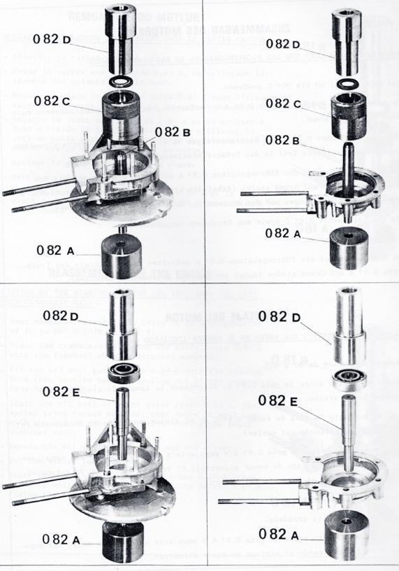
4 0.81A - Guide piece 0.81B - Driver 0.81C - Oil seal guide piece 0.82A -Socket 0.32B - Guide piece 0.82C - Oil seal guide piece 0.82D - Driver 0.82E - Guide piece For replacing the oil seal and ball bearing in the LH crankcase half For replacing the oil seal and ball bearing in the RH crankcase half Pulley hub fixing tool Stop-pin wrench Distance pin 4
 centering tool 0.103 - Drum fixing tool 0.104 - Torque wrench J.11H - Socket J.14H - Socket J.")
5 Driven pulley assembling and disassembling tool Engine bearing frame Gudgeon pin (wrist pin) centering tool Drum fixing tool Torque wrench J.11H - Socket J.14H - Socket J.17H - Socket J Extension tool 5

6 0.106B - Tapered driving nut extractor Belt tension checking tool Ignition advance timing tool Holding strap 6
7 MAIN TECHNICAL DATA 2-stroke engine with pre-compression in the crankcase Bore and stroke: 40x39mm Cubic capacity: 49cc Compression ratio: 7.4 to 1 all types but reed valve engine: 8.4 to 1 Ignition: flywheel magneto Ignition advance: timing marks 2.5mm Ignition advance: timing marks 1.5mm on reed valve engine Primary transmission: V-belt Fuel consumption: 1.8 liters per 100 km (about 158 miles per one gallon) Tank capacity: front tank = 3.7 liters (0.815 gallons), rear tank = 3.2 liters (about 0.69 gallons) Spark plug: for short trips with many starts = Marchal D, for road service, Marchal 35, for long rips or mountain roads, Marchal 34 S. 7
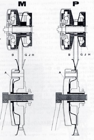
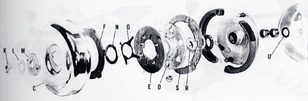
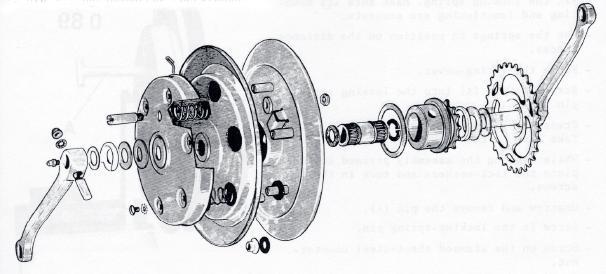
8 AUTOMATIC PLATE-CLUTCH, 120MM DIAMTER Description The clutch system has the following two main parts: 1) The starting clutch, consisting of 2 cranking shoes (A) which attach to the driving pulley (B). Due to the centrifugal force, these shoes transmit motion to an outside drum (C) which is rigidly locked with the crankshaft. 2) The automatic plate clutch, consisting of a drum (D) which bears 6 balls, a pressure-plate (E) and a lining (F). The outside edge of the lining is notched so it can be rigidly locked with the driving pulley. Operation The driver s actuation of the pedals at first transfers the motion to the rear wheel through the crankgear chain, secondly to the large intermediate pulley through the driving chain, then to the starting clutch over the small pulley which is driven by the belt. As soon as the speed reaches about 8km per hours (5mph), the starting clutch sets to work and it cranks the engine over, thus starting it. Once the engine runs, the operation of the throttle will cause the rotation speed to increase. Due to centrifugal force, the balls tend to move away from the center. The drum (D) being used as a support, the balls bring out an axial thrust which forces the pressure-plate (E) against the lining (F), the latter being in contact with the drum (C). The lining, thus rigidly locked with both the pressure-plate and the drum, transfers motion to the pulley by means of its notches, and so the engine rotation is transmitted to the rear wheel over the belt and the driving chain. AUTOMATIC PLATE-CLUTCH AND VARIABLE SPEED TRANSMISSION Description The automatic plate-clutch with variable speed transmission unit has the following two main parts: 1) The drive pulley, consisting of the tight flange (B) which bears the cranking shoes, and the moving flange (G), which can travel sideways. A centrifugal weights system is built-in between the moving flange (G) and the nylon deflector plate (H). The centrifugal force enables this system to control the width of the groove between both flanges of the pulley. 2) The driven pulley, consisting of two flanges which are kept pressed together by six springs. Operation At starting, and as a general rule while the speed is low, the reduction ratio is high and squares with a normal first gear. The belt travels around the driving pulley at the bottom of the groove and at the periphery of the driven pulley groove. Through an increase of the engine RPM, the centrifugal force operates, and the built-in centrifugal weights, using the nylon deflector plate (H) as a support, push the moving flange (G) back towards the tight flange (B). By doing so, they compel the belt to climb up the flanges of the driving pulley groove to its periphery. This variation is a continuous one. It happens without any interference of the driver. Therefore it is better than a gear shift. It is actually an automatic speed variation. 8

9 While the diameter of the driving pulley variates automatically in the way explained above, the diameter of the driven pulley changes in the inverted way, but not by the same amount, as it is actuated by its springs. See below for additional image. 9
10 10


11 DISASSEMBLING THE ENGINE Engine stand The opposite figure shows an engine stand which is very handy and can be used for all the engines which are made in our works. The engine is mounted on a rotating shaft which may be locked in four different positions, making all parts easily accessible. This engine bearing frame is supplied by our spare parts distributor under part Nr Removing the cylinder head and cylinder -Take off the spark plug boot -Remove the spark plug Removing the cylinder head and cylinder -Loosen and remove the 4 nuts holding they cylinder head. Operate crosswise to avoid warping. Remove the cylinder head and its gasket. -In case the cylinder is stuck tight, set the piston at its lowest point (bottom dead center) and strike light blows with a rubber mallet on the exhaust pipe. (Never hammer on the cooling fins, because they are very fragile). Use caution to avoid damage to the gasket while removing the cylinder. -Remove the base gasket. Removal of the decompression valve -Fasten the cylinder head using two bolts in a vice -Clip off the end of the pin, then compress the spring and remove the pin -Take off the valve Removal of the decompression body -Fasten the cylinder head as explained above -Insert a screwdriver into the hairpin spring and open it until it can be slipped over the head of the decompressor body. -Screw out the decompressor body using a 19mm pipe wrench -Do not remove the compressed copper gasket if it is not damaged. 11


12 Removing the piston 1) Remove the two gudgeon pin retainers using the special pliers ) Drive out the gudgeon pin using the tool Be cautious with the needle bearing races. DISASSEMBLING THE MAGNETO FLYWHEEL Removing the flywheel -Take off the flywheel cover -Remove the nut at the end of the crankshaft using a 16mm pipe wrench while immobilizing the rotor with the holding strap Screw back the thrust bolt of the extractor 0.45 without removing it completely. Then put that tool into the position by screwing it onto the rotor until it bottoms. -Hold the body of the tool using a 21mm wrench, screw in the thrust bolt of the extractor using a 17mm wrench until the rotor disengages. Removing the stator: -Screw out the two cylindrical head screws, using a screwdriver -Caution: Do not erroneously remove the countersunk screws with raised heads holding the breaker. -Take out the stator -Push the grommet inside of the flywheel magneto and disconnect the lighting wire. Use caution to avoid damage to the connecting plug. 12
 using a 17mm pipe wrench or torque wrench while holding the clutch box, using the strap 0.")
 -Remove together the pressure plate (E) and the drum (D) bearing the balls, and the balls. Pull the tapered driving nut (R) off the crankshaft.")
13 DISASSEMBLING OF THE PLATE-CLUTCH (WITH OR WITHOUT THE VARIABLE SPEED TRANSMISSION) -Remove the ball lubricator located at the shaft end (engine with variable speed transmission) -Unlock the tab-washer of the nut -Untighten the nut (right hand thread) using a 17mm pipe wrench or torque wrench while holding the clutch box, using the strap Remove in the following order: -the nut (K) -the tab-washer (L) -the washer (M) -the clutch box (C) -the adjusting washer (N) -the spring (O) -the lining (F) (mark the outside surface of the lining in order to put it back the same way it was) -Remove together the pressure plate (E) and the drum (D) bearing the balls, and the balls. Pull the tapered driving nut (R) off the crankshaft. To do so, use the extractor B. Removing the clutch shoes The driving pulley assembly is to place onto a bench, with its shaft in a vertical position. -Untighten and screw out the nuts attaching the locking ring (S), remove the lock-washers, and remove the locking ring. -Unlock the retracting springs off the studs of the shoes. Do not forget to mark the way they were hooked on (1 st or 2 nd stud). -Take the shoes off. Removing the needle bearing races (clutch without variable speed transmission) The needle bearing races are forced into the pulley bore. To drive them out, use the proper driving tool (do not heat). 13
 and the centrifugal weights with holder (J) -Take out the 4 distance pieces -Remove the moving flange (G) -Remove the")

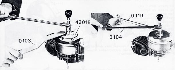
14 DISASSEMBLING THE VARIATOR -Unlock the tab-washers of the 4 holding bolts -Untighten the 4 bolts and take them out (8mm wrench) -Remove the stiffening plate (T) -Remove the nylon deflector plate (H) and the centrifugal weights with holder (J) -Take out the 4 distance pieces -Remove the moving flange (G) -Remove the needle bearing race Removing the variable speed transmission pulley hub -Engage the pulley hub onto the tool 0.87 previously gripped in a vice. -Insert the stop pins of the wrench 0.88 as shown on figure. -Put a pin into the lubrication hole. -Turn the stop-pin wrench 0.88 clockwise to screw out the hub (left hand thread) 14
15 REMOVING THE REED VALVE SYSTEM -Unscrew the 4 nuts holding on the intake manifold -Remove in the following order: -the spring washers -the intake manifold -the first gasket -the reed valve assembly -the second seal Be careful to not alter the shape of the reed valve stops while removing the reed valve assembly. 15


16 DISASSEMBLING THE CRANKCASE HALVES (A) Crankcase halves with unremovable rear bracket (right) -Unscrew the nuts assembling the crankcase halves -Put in place the tool 0.47 on the flywheel magneto side of the right hand crankcase half, while securing it by means of the two screws part Nr H5-15 onto the pair. -Use the driving attachment 0.47D -Screw up until he crankcase halves come off completely (B) Crankcase halves with removable rear brackets (below) -Unscrew the nuts assembling the crankcase halves -Take out the screws -Pull out the crankcase halves from the brackets which remain fixed to the engine bearing frame 0,91 -Put in place on the flywheel magneto side of the right hand crankcase-half the tool 0.47 and the distance piece taking place on the 48 (diameter) centring. -Use the driving attachment 0.47D -Screw up until the crankcase halves come off completely. 16

17 Left hand crankcase half removing the crankshaft assembly The tool 0.47 has to be used together with the distance piece previously placed on the 39.2 diameter centering used against the crankcase half between the tool 0.47, before securing the latter by two bolts inserted into the crankcase assembly holes. -Screw up until the crankshaft comes out completely. Removing the bearings -Put the crankcase half down to rest on its mounting surface -Heat and cautiously strike very light blows on the crankcase half until the bearing falls out by itself. 17

 -Remove the oil seal guide piece and the driver.")
18 REASSEMBLING THE ENGINE Fitting the bearing and oil seal into the left hand crankcase half -Heat the crankcase half to bring it to a temperature of degrees C ( F). -Place the crankcase half onto the guide piece 0.81A with the flywheel chamber directed upwards -Fit the oil seal guide piece 0.81C into the bearing bore (the knurled part projecting out of the crankcase half). -Start the oil seal onto the guide piece 0.81A, the spring being turned outside, then drive it in with the aid of the driver 0.81B (using the smaller diameter end) -Remove the oil seal guide piece and the driver. -Put the washer into position. -Start the bearing onto the guide piece 0.81A, then drive it in with the aid of the driver 0.18B (using the large diameter end) 18
19 19
 into the socket 0.")
 -Start the oil seal onto the guide piece 0.82B (the spring being turned upwards).")
20 Fitting the bearing and oil seal into the right hand crankcase half -Heat the crankcase half to bring it to a temperature of degrees C ( F) -Place the guide piece 0.82B (16mm diameter) into the socket 0.82A -Put the crankcase half onto the tool with the flywheel chamber turned upwards -Position the felt seal onto the crankcase half -Fit the oil seal guide piece 0.82G into the bearing bore (the knurled part projecting out of the crankcase half) -Start the oil seal onto the guide piece 0.82B (the spring being turned upwards). Drive it in with the aid of the driver 0.82D, using the small diameter end). -Remove the driver 0.82D and the oil seal guide piece 0.82C -Without taking the crankcase half off the socket, remove the guide piece 0.82B (16mm diameter upwards) and replace it by the guide piece 0.82E (17mm diameter by 16mm), sliding the latter through the oil seal. -Put the bearing thrust washer into position in the crankcase half. -Start the bearing onto the guide piece 0.82E and drive it in with the aid of the driver 0.82 D, using the large diameter end. Fitting the crankshaft into the left hand crankcase half -Slide the thrust washer into position on the crankshaft (only in case of crankshaft assembly with shrunk-on shafts) -Put the distance piece on the 39.2 diameter centering against the crankcase half. -Place the tool 0.47 onto the distance piece used as a support. -Screw the tool attachment 0.78D onto the crankshaft end, and screw down the nut 0.78A until the crankshaft bottoms in the crankcase half. 20
 --Place the tool 0.47 onto the pair of stator supporting bossings. -Screw the tool attachment 0.")
21 Fitting the left hand crankcase half with the crankshaft in the right hand crankcase half A) Crankcase halves with unremovable rear bracket -Slide the thrust washer into position on the crankshaft (only in case of crankshaft assembly with shrunk on shafts) --Place the tool 0.47 onto the pair of stator supporting bossings. -Screw the tool attachment 0.78B onto the crankshaft end, and screw down the nut 0.78A until the crankshaft bottoms in the crankcase half. 21

22 (B) Crankcase halves with removable rear brackets -Slide the thrust washer into position on the crankshaft (only in case of crankshaft assembly with shrunk on shafts) -Put the distance piece on the centering 48 diameter of the crankcase half. -Place the tool 0.47 onto the distance piece used as a support. -Screw the tool attachment 0.78B onto the crankshaft end, and screw down the nut 0.78A until the crankshaft bottoms in the crankcase half. 22

23 Important: -Take care that the crankcase halves are properly positioned. -For that purpose, centring screw Nr has been adjusted to a 5.8mm diameter; put it into the right place. -Do not forget to turn the crankshaft to be sure it rotates freely. If necessary, put it in position by lightly striking light blows of a hammer on one of the shaft ends. 23
24 Reassembling the reed valve system -Before reassembling the reed valve, make sure the two stops have not been warped. If necessary, readjust their width to 5mm, which should never be changed. -Assemble in the following order: -the first gasket -the reed valve assembly -the second gasket -the intake manifold -the four washers and nuts 24

25 Reassembling the piston -Check the piston ring gap. It should not exceed a maximum of.3mm. Position the piston rings in the cylinder bore and check the gap with a feeler gauge. -Place the rings on the piston. -If necessary, clean out the wrist pin retainer grooves. -Place the piston into the assembling tool 0.12 so as to have the piston rings correctly positioned by the stops. -Start the gudgeon pin into its bore until it is flush with the inner bossing. -Dip the needle bearing race in light oil. Then, fit it into the connecting rod bore. -Position the tool 0.12 with the piston inside on the connecting rod, the reference letter being directed frontwards. -Insert the centering tool 0.93 through the needle bearing race into the gudgeon pin hole for positioning. -Push the pin as far as ¾ of its way in. -Then, remove the centering tool 0.93 and fit on one of the gudgeon pin retainer rings (pliers 0.4). -Drive the wrist pin further in until it is bottomed on the first fitted wrist pin clip. -Remove tool 0.12 and fit on the second wrist pin clip. -Make sure the retainer rings are well seated in their grooves. 25
 -Place the gasket on the cases -Put the piston down to rest on the wooden U-board mentioned above Important: Make sure the")
26 Refitting the cylinder In order to simplify this operation, we recommend a wooden tool as shown in the image. -Clean the mounting surface (the crank cases and the bottom of the cylinder) -Place the gasket on the cases -Put the piston down to rest on the wooden U-board mentioned above Important: Make sure the piston ring gaps are accurately facing the stops which are located in the grooves. -Start in the cylinder well in line, without any striking, the chamfer which is well machined at the base of the cylinder bore is there to help close in the piston ings. -Remove the wooden U-board and push the cylinder down until it is flush with the crankcases. 26
27 Reassembling the decompression valve Caution: The tightness of the valve has a vital effect on the performance of the engine. Thoroughly check the valve seat and the valve before refitting it. If the valve face shows any kinds of defects, replace the valve or the entire assembly. -Make sure that the copper gasket is fitted. -Tighten the decompressor body vigorously on the cylinder head (19mm wrench) -Insert the valve stem into the decompressor body. -Fit the valve spring. -Put in the pin, and secure it by riveting its end. In case the pin comes loose, the valve falls into the cylinder. Fitting the cylinder head -Place the gasket. Make sure it is oriented in the right direction. The hole provided in the top of the cylinder to let air escape (decompression valve) must match the hole in the gasket. -Install the cylinder head, positioning it the same way as the gasket. -Install the brackets attaching the engine. They have to be directed rearwards. Place the spring-washers and the nuts onto the studs. The nuts must be screwed in and securely tightened crosswise, using an 11mm wrench or a torque wrench (torque to 1.1m Kg). 27


28 REASSEMBLING THE CLUTCH Fitting the needle bearing races and the oil seal (clutch without variable speed transmission) It is recommended to engage the races with caution, and to use the proper driving tool. The sides of the races bearing the marks must be turned outside. The oil seal is easy to fit by hand. It must be placed in such a way as to turn the open side towards the needle bearing race. Fitting the clutch shoes -Place onto a shoe the large hook of the retracting spring inside the articulation milling, then position this assembling onto the anchor pin. -Do this again fitting the other shoe. -Hook the retracting sprigs onto the shoe studs. When the springs are in the right position, the open side of their hooks must be turned towards the inside of the device. On mopeds without variable speed transmissions, the springs are to be hooked on short, that is onto the first stud. On mopeds with variable speed transmissions, the springs are to be hooked on long, that is onto the second stud. -Fit the locking ring (S). The two nuts, part Nr HU-5, have to be tightened in such a manner as to bring one of their flanks to be parallel to the outer edge of the lining locking stops (F). 28

 -the nylon disc -the centrifugal weights smeared with grease with their holder (J). Caution: the rounded flank must be turned towards the moving flange.")
29 REASSEMBLING THE VARIABLE SPEED TRANSMISSION -Screw the tight flange (B) bearing the starting clutch onto the pulley hub (left hand thread). Use the tool 0.87 together with the stop-in wrench 0.88 to tighten it. -Lubricate the needle bearing races with grease and fit them into their housing, following the order given below: -the nylon seal -the needle bearing races after having assembled them Then fit: -the moving flange (G) -the nylon disc -the centrifugal weights smeared with grease with their holder (J). Caution: the rounded flank must be turned towards the moving flange. -the distance piece -the reinforcing washer -the nylon deflector plate (H) -the stiffening plate (T) -start in the bolts, tightening them, bend the tab washers (in case they are worn out, replace the stiffening plate). 29
30 Fitting the assembly onto the crankshaft -Make sure that the adjusting washer (U) is in position (for the model with variator, thickness =2mm, for the model without variator, thickness = 1mm) -Coat the rear support surface of the pulley hub with grease (use ball bearing grease). -Fit the driving pulley assembly (or the variable speed transmission and tight flange assembly) onto the crankshaft, the needle bearing races and the oil seal being in position -Carefully remove all grease from the male taper on the crankshaft using pure petrol and fit in the following order: -the nylon washer (V) -the tapered driving nut (R), its inner surface being lubricated but the inner taper being perfectly clean and free from grease -Onto the tapered driving nut, place an outer thrust plate, part Nr (fitted part on the clutch with diameter 100mm, drawing Nr. 19, page 10 of the catalog C-CT-VCT-LT-VLT 1967 edition) -Start the nut (K) onto the thread of the crankshaft. -Hold the plate Nr by means of the tool and tighten the nut using a torque wrench (torque to 3mKg). -Make sure the axial clearance of the pulley is about mm. -Untighten the nut (K) and remove it as well as the outer thrust plate Nr Then, assemble onto the tapered driving nut: -the drum (D) -the 6 balls (12mm diameter), very slightly coated with a mineral lithium-graphite type grease (do not use any other type of grease) -the pressure plate (E) -the linings (F) -the spring (O) -the adjusting washer (N) -the clutch box (C) While holding the clutch box, fit: -the washer (M) -the tab washer (L) -the nut (K) -Screw in the nut and tighten it using a torque wrench (3m Kg) while firmly holding the clutch box by means of the strap check the lateral functioning clearance of the assembly on the crankshaft. If must remain within the limits of 0.4 to 0.6mm. -Lock the tab washer by bending it against the nut. -Fit the ball lubricator (engine with variator) -Lubricate moderately with BP Multipurpose Energrease L2 30
31 31
, the functioning clearance which should be found between the lining (F) and the pressure plate (E) must be checked as well.")
32 ADJUSTING THE AUTOMATIC PLATE-CLUTCH In the case of the clutch working badly and after making sure that the pulley slides freely on the crankshaft (axial clearance about mm), the functioning clearance which should be found between the lining (F) and the pressure plate (E) must be checked as well. This check should be made as follows: -On a shaft gripped vertically in the jaws of a vice (use the clutch-side crankshaft half) assemble in the following order: -the tapered driving nut (R) -the drum (D) -the six balls -the pressure plate (E) -the lining (F) -the spring (O) -the adjusting washer (N) -an outer thrust-plate Nr the washer (M) -the tab-washer (L) -the nut (K) Firmly tighten the assembly using a torque wrench (torque to 3m Kg). Use a feeler gauge to check the functioning clearance between the lining (F) and the pressure plate (E). That clearance should remain within the limits of mm. In case the clearance is found to be out of the above limits, replace the adjusting washer (N) by another one the thickness of which, when properly chosen, will give the recommended clearance. That adjusting washer can be supplied with the following thickness measures: 1.2, 1.4, 1.6, and 1.8 mm. 32


33 REASSEMBLING THE FLYWHEEL MAGNETO -Put the stator in position on the crankcase half -Carefully fit the rubber grommets which are to keep the flywheel watertight into the right crankcase half. In case they are in bad condition, replace them. -Drive in the two attaching screws with a lock-washer under the screw head. Setting the ignition timing -Screw the tool into the spark plug hole. -Screw in the locking screw of the upper gliding rod, but do not tighten it. -Find top dead center (TDC) by rotating the clutch box. -Tighten the screw firmly to lock the upper gliding rod. -Rotate the clutch box in the opposite direction of normal engine operation in order to let the lower gliding rod go down. -Insert a feeler gauge between the ends of the two gliding rods: 1.5mm on the reed valve engines, and 2.5mm on all other engines. Continue to rotate the clutch box in the same direction until the feeler gauge gets stuck tight. -Without moving the piston, turn the rotor until its timing mark 2 matches the timing mark 1 of the stator. -Tighten securely the rotor in that position using the holding strap and the torque wrench (torque to 2.5 mkg). 33
.")
34 Timing adjustment of the points -Place the rotor mark 1 and the stator mark 2 so as to have them face each other. Untighten the points -insert a screwdriver between the adjusting notches and actuate them until the breaker points just start to open in that position (use the test tool 0.98 to check this operation). Then tighten the breaker point holding screw securely. Very important: When the timing adjustment is accurate, the maximum gap between the breaker points is about 0.4mm. Nevertheless, that gap can vary from mm without any adverse effects. Do not adjust the gap between the breaker points on a definite width. The proper functioning of the magneto flywheel does not depend on the gap value itself, but on the precision of the breaker points opening and the very moment the rotor and stator marks face each other. 34
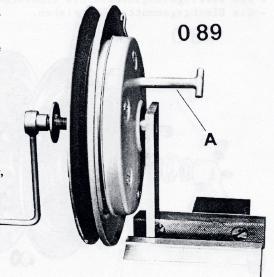
35 DISASSEMBLING AND REASSMELBING THE DRIVEN PULLEY Disassembling -Position the locking device on bicycling -Take out the intermediate sprocket -Unscrew and remove the stamped sheet-steel nut -Unscrew the locking spring pin and take it out -Press the assembly together using the tool Remove the screws with their lock washers -Release the assembly and remove: -the spring cover -the springs -separate the flanges -remove the locking-stop -Remove the retainers and the needle bearing races Reassembling -Put the nylon bushing into its housing in the mobile flange -Place the rubber washers onto the distance pieces, the thin washer onto the distance piece bearing the nylon bushing -Lubricate with grease and put the locking stop onto its housing (the taper being turned centerwards), directing the locking stop hole towards the port of its housing. -Put the intermediate sprocket in position. -Fir the second flange of the pulley, taking care of its accurate positioning (the port of the distance piece with the fitting in must be located diametrically opposite of the locking spring.) -Fit the locking spring. Make sure its mounting and functioning are accurate. -Put the springs in position on the distance pieces. -Place the spring-cover. -Screw the pin (A) into the locking spring pin hole. -Press the assembly together (tool 0.89). Take care of the locking-spring. -While keeping the assembly pressed together, place the lock washers and turn in the 6 screws. -Unscrew and remove the pin (A). -Screw in the locking-spring pin. -Screw on the stamped sheet-steel counter-nut. 35
36 36

37 BELT TENSION ADJUSTING (A) Mopeds with variable speed transmission: The two flanges of the driven pulley are always pressed together by the springs. Thus, the belt is tensioned. If too loose, the tension causes the belt to slip. A belt that is too tight reduces the variation range of the device. Checking the belt tension: At a standstill, the back of the belt should normally remain underneath the outer circumference of the large pulley by 2-3mm (to be measured on the upper belt section). Adjusting: To perform the adjustment, tip over the engine frontwards and rotate the driven pulley by hand in the direction of normal operation until the belt is correctly positioned as explained above. Then, tighten securely the rear and front attaching bolts of the engine. (B) Mopeds without variable speed transmission To perform the adjustment, tip over the engine frontwards (to do so, use the tension tool 0.114). The belt deflection should not exceed a maximum of 1cm when the belt is pushed in with the finger between the two pulleys. 37
 Reed valve engine, intake through crankcase D.12.D. type, inlet diameter 12mm, adjustment 713, main jet 250 (engine with variable transmission) D.")
38 CARBURETOR Description: Gurtner carburetor with sedimenting bowl Engine with cylinder intake: D.12.D type, inlet diameter 12mm, adjustment 666, main jet 230 (engine with variable transmission) D.10.D type, inlet diameter 10mm, adjustment 665, main jet 200 (engine without variable speed transmission) Reed valve engine, intake through crankcase D.12.D. type, inlet diameter 12mm, adjustment 713, main jet 250 (engine with variable transmission) D.10.D type, inlet diameter 10mm, adjustment 716, main jet 240 (engine without variable transmission) The carburetor is preadjusted by leaving the factory. Only the idle run may be reset, but this idle adjustment is very important. When the vehicle is at a standstill, a good setting allows the engine to run smoothly so the moped can start easily when the throttle is applied. The idle screw has to be adjusted while the engine is warm, by setting the scew located on the lft side of the carbuettor (thes crew can be reachd through a port in the left hand engine fairing). Adjusting: -Start the engine (the moped on the stand) -Put the throttle in the closed position -Turn in the adjusting screw until it is all the way in. -When the engine is warm, slowly turn out the adjusting screw as to set the engine speed as low as possible. The rear wheel should not be driven. -Once the engine idle speed is sufficiently slow, take the moped off the stand and get on. The engine should not stall. 38

39 DISASSEMBLING THE FRONT FORKS The disassembling of the front fork is only necessary in case of an inspection, for this fork needs no maintenance other than lubrication. -Disconnect the brake controls and the speedometer drive. -Remove the front wheel. -Unclamp the front brake and speedometer cable sheaths -Untighten and remove the blind nuts on top of the upper fork plate, then remove the assembly. -To take out the springs, untighten and remove the bolts attaching the mudguard stay to the form, and pull out the assembly, rod, and spring. 39
SALES DIVISION NETWORK TECHNICAL INFORMATION WORKSHOP MANUAL MOTOR ENGINE
 SALES DIVISION NETWORK TECHNICAL INFORMATION WORKSHOP MANUAL MOTOR ENGINE CONTENTS CHARACTERISTICS... 5 Engine markings... 5 TIGHTENING TORQUES... 5 SPECIAL TOOLS... 6 IDENTIFICATION... 7 Differences between
WORKSHOP MANUAL TECHNICAL NETWORK LEADERSHIP WORKSHOP MANUAL 125 CC/150 CC 4-STROKE ENGINE
 WORKSHOP MANUAL TECHNICAL NETWORK LEADERSHIP WORKSHOP MANUAL - 5 CC/50 CC 4-STROKE ENGINE Workshop manual Technical network leadership TABLE OF CONTENTS TABLE OF CONTENTS TABLE OF CONTENTS... CHARACTERISTICS...
20.Cylinder Block. Cylinder Block A: REMOVAL ME(H4DOTC)-63 ST CRANKSHAFT STOPPER
-63 ST CRANKSHAFT STOPPER") Cylinder Block MECHANICAL 20.Cylinder Block A: REMOVAL Before conducting this procedure, drain engine oil completely. 1) Remove the intake manifold. 2)
Cylinder Block MECHANICAL 20.Cylinder Block A: REMOVAL Before conducting this procedure, drain engine oil completely. 1) Remove the intake manifold. 2)
Transmission Overhaul Procedures-Bench Service
 How to Assemble the Lower Reverse Idler Gear Assembly Special Instructions In 1996 Eaton changed the reverse idler system design. In the nut design, the reverse idler bearing was lubricated through a hole
Remove Air Cleaner Cover and. Filter
 Remove Air Cleaner Cover and Inspect paper filter for tears Foam pre-cleaner is washable if equipped Replace if necessary Filter Remove Trim Panel Pull throttle lever knob off Remove 3, 8mm screws Remove
HKS 700E. Service Manual June Ver. 2.04
 HKS 700E Service Manual 009 June Ver..04 HKS CO.,LTD 78 KITAYAMA FUJINOMIYA SHIZUOKA JAPAN 48-09 TEL +8(0)544-54-78 FAX +8(0)544-54-40 hks_aviation@hks-power.co.jp http://www.hks-power.co.jp/hks_aviation/
CARTER DOWNDRAFT CARBURETOR Terraplane All Models. Technical Information
 CARTER DOWNDRAFT CARBURETOR 1934 Terraplane All Models Technical Information . Carter W-1 Downdraft Carburetors 1934 Terraplane Challenger, Model KS NOTE: Terraplane Models. Carburetor fitted with Anti-
Drawing A Crankcase 041 AV SCS
 Drawing A Crankcase 1 Drawing A Crankcase Reference Item number Qty Description 1 1110 020 2105 1 Crankcase 2-5, 9, 10, 12 2 9371 470 3120 2 Cylindrical pin 6x20 3 9048 216 1010 8 Pan head screw M5x18
MODELS 3100,3130,3160, 1300, 1330,1360 EXHAUST SYSTEM
 MODELS 3100,3130,3160, 1300, 1330,1360 EXHAUST SYSTEM WALBRO CARBURETOR "WA" SERIES MUFFLER REMOVAL CARBURETOR REMOVAL The muffler assembly should beremoved periodically to inspect for excessive carbon
1989 Jeep Cherokee. STEERING COLUMN' '1989 STEERING Jeep Steering Columns STEERING COLUMN STEERING Jeep Steering Columns
 STEERING COLUMN 1989 STEERING Jeep Steering Columns DESCRIPTION All models use collapsible steering columns. All columns have integral ignition switch and locking device. Optional tilt wheel is available
XL12 Chain Saw UT Page 1 of 21 Carburetor Chamber
 XL12 Chain Saw UT-10080 Page 1 of 21 Carburetor Chamber XL12 Chain Saw UT-10080 Page 2 of 21 Carburetor Chamber 1 59274 1 GASKET- Spacer 2 59718 1 SPACER 3 63260A 1 RETAINER- Reed valve 4 63253 1 SEAT-
Printed from MediaCat
 Illustration A Crankcase Illustration A Crankcase Ref.Nr. Item code Quantity Description 1 1106 020 2506 1 Crankcase (2) 2-11 2 0000 988 5217 1 Connector (2) 3 0000 988 5200 2 Connector (2) 4 1106 641
CARBURETION. Carburetor Identification. Models , , , , , , , , , , ,
 Carburetor Identification Models 110400, 110600, 111400, 111600, 113400, 120400, 120600, 121400, 121600, 122600, 123400, 123600 Models 28S700, 311700 Service Carburetor Briggs & Stratton/Walbro LMS Models
I. TWO-STROKE MECHANICAL EN- GINE PARTS
 I. TWO-STROKE MECHANICAL EN- GINE PARTS 1. UNIBLOCK ENGINES (AV520-600-750-125) a) INTRODUCTION Fig. 1 shows the short block. Fig. 2 shows an exploded view of the engine. As may be seen the momoblock is
SPECIFICATIONS TEST AND ADJUSTMENT SPECIFICATIONS SPECIFICATIONS ENGINE FD620D, K SERIES
 TEST AND ADJUSTMENT Engine Oil Pressure Sensor Activates............................... 98 kpa (14.2 psi) Oil Pressure While Cranking (Minimum).......................... 28 kpa (4 psi) Oil Pressure.....................................
1.8L & 2.2L 4-CYL Article Text 1998 Subaru Impreza
 1.8L & 2.2L 4-CYL Article Text 1998 Subaru Impreza ARTICLE BEGINNING 1995-98 ENGINES Subaru - 1.8L & 2.2L 4-Cylinder 1995-97: Impreza (1.8L) 1995-98: Impreza (2.2L), Legacy (2.2L) * PLEASE READ THIS FIRST
Vespa LX 50 4valvole. Refitting the valves. Inspecting the cam shaft. Characteristic. Engine
 Refitting the valves - Lubricate the valve guides with graphite grease. - Place the lower caps of the valve spring on the head. - Use the punch to fit the 4 sealing rings one at a time. - Fit the valves,
SXLAO Chain Saw UT Page 1 of 21 Carburetor Chamber
 SXLAO Chain Saw UT-10045 Page 1 of 21 Carburetor Chamber SXLAO Chain Saw UT-10045 Page 2 of 21 Carburetor Chamber 1 59274 1 GASKET- Spacer 2 59718 1 SPACER 3 63260A 1 RETAINER- Reed valve 4 63253 1 SEAT-
MANUAL INDEX. Page 1. LEOPARD 125cc ENGINE DISASSEMBLY CRANKSHAFT DISASSEMBLY/ ASSEMBLY CRANKSHAFT DISASSEMBLY 8
 MANUAL INDEX Page 1. LEOPARD 125cc ENGINE DISASSEMBLY 1 2. - CRANKSHAFT DISASSEMBLY/ ASSEMBLY 8 2.1- CRANKSHAFT DISASSEMBLY 8 2.2- CRANKSHAFT ASSEMBLY 10 3. LEOPARD 125cc ASSEMBLY 13 4. - CHECK CYLINDER
A/C COMPRESSOR SERVICING Article Text 1991 Saab 9000 For Copyright 1997 Mitchell International Friday, October 15, :22PM
 Article Text ARTICLE BEGINNING 1991 GENERAL SERVICING Compressor Service * PLEASE READ THIS FIRST * CAUTION: When discharging air conditioning system, use only approved refrigerant recovery/recycling equipment.
E02 CYLINDER HEAD COVER ASSY
 TNG 150cc ZT E01 FAN COVER ASSY 1 BN0061-1 Clip 1 2 150ZT-E01.02 BN0064 Fan Cover 1 3 BN0061-2 Bracket 1 4 150ZT-E01.04 BN0064-4 Carburetor Cooling Duct 1 5 150ZT-E01.05 BN0064-3 Decorative Cover 1 6 150ZT-E01.06
SPECIFICATIONS TEST AND ADJUSTMENT SPECIFICATIONS SPECIFICATIONS ENGINE FD620D, K SERIES
 ENGINE FD620D, K SERIES SPECIFICATIONS SPECIFICATIONS TEST AND ADJUSTMENT SPECIFICATIONS Engine Oil Pressure Sensor Activates............................... 98 kpa (14.2 psi) Oil Pressure While Cranking
Super 1050 Chain Saw UT Page 1 of 16 Carburetor Chamber
 Super 1050 Chain Saw UT-10139 Page 1 of 16 Carburetor Chamber Super 1050 Chain Saw UT-10139 Page 2 of 16 Carburetor Chamber 1 58319A 1 RING- Retaining 2 592301 1 COVER- Air filter 3 A70326 1 NUT- Cover
REEDSTER 125cc. versions: F1 - F2 - F3 - F4 OVERHAULING MANUAL
 REEDSTER 125cc versions: F1 - F2 - F3 - F4 OVERHAULING MANUAL 07/11/07 21/01/2009 1 INDEX Page 1. - REEDSTER 125cc ENGINE DISASSEMBLY 1 2. - CRANKSHAFT DISASSEMBLY / ASSEMBLY 13 2.1 - CRANKSHAFT DISASSEMBLY
Hudson-Essex. Service Manual Supplement. Hudson Cars 750,001 up
 1 9 2 6 Hudson-Essex Service Manual 1927 Supplement Hudson Cars 750,001 up Hudson Rear Axle (Cars numbered 750,001 and upward) Brakes (Cars numbered 750,001 and upward) See page 18 Transmission Group
13. CRANKCASE/CRANKSHAFT/BALANCER/PISTON/CYLINDER
 13. CRANKCASE/CRANKSHAFT/BALANCER/PISTON/CYLINDER COMPONENT LOCATION 13-2 SERVICE INFORMATION 13-3 TROUBLESHOOTING 13-4 CRANKCASE SEPARATION 13-5 CRANKSHAFT 13-7 MAIN JOURNAL BEARING 13-9 CRANKPIN BEARING
Disassembly and Assembly
 SENR9973-01 September 2007 Disassembly and Assembly 400C Industrial Engine HB (Engine) HD (Engine) HH (Engine) HL (Engine) HM (Engine) HN (Engine) HP (Engine) HR (Engine) Important Safety Information Most
Batavus M48 Tech Notes
 Batavus M48 Tech Notes SPARK PLUG SPECS The spark plug is an important part of the engine. Two temperatures are very important for the spark plug. First, the temperature at which the spark plug burns itself
235/245400, , 28N
 Models 235/245400, 287000, 28N thru W, 310/312/313700 These carburetors have a fixed high speed main jet with adjustable idle, Fig 183. The different carburetors are identified as LMT 1 and up. The letters
88cc Big Bore Kit Install Instructions
 88cc Big Bore Kit Install Instructions Before installing a big bore kit, you should first install a high volume oil pump. A high volume oil pump will deliver up to 300% more oil to your top end which will
Fig. 6: Assembling Piston & Rod. NOTE: Notch must face forward Toyota Starlet CRANKSHAFT MAIN BEARINGS
 connecting rods are marked for reassembly. 3. Thoroughly clean and inspect all components. Coat pin with engine oil and heat piston to 158-176 F (70-80 C). Pin should push fit with thumb pressure through
10. ALTERNATOR/STARTER CLUTCH
 10. ALTERNATOR/STARTER CLUTCH SYSTEM COMPONENTS 10-2 SERVICE INFORMATION 10-3 TROUBLESHOOTING 10-3 LEFT CRANKCASE COVER REMOVAL 10-4 STATOR/IGNITION PULSE GENERATOR 10-5 FLYWHEEL/STARTER CLUTCH 10-6 LEFT
Printed from MediaCat
 Illustration A Crankcase, Cylinder Illustration A Crankcase, Cylinder Ref.Nr. Item code Quantity Description 1 1113 020 2107 1 Crankcase (1,2,4,5,7,8) 2-11 1 1113 020 2108 1 Crankcase (3,6) 2-11 2 1113
Maintenance Information
 45528270 Edition 1 June 2007 Barring Motor T480 Series Maintenance Information Save These Instructions WARNING Always wear eye protection when operating or performing maintenance on this Barring Motor.
 AUTOGARD SERIES 820 TORQUE LIMITER Installation and Maintenance Manual DB0009 Issue 11 21 Feb 2017 British Autogard Ltd 2 Wilkinson Rd., Love Lane Industrial Estate, Cirencester, Glos., GL7 1YT UK Tel.
Chapter 5 Part B: Ignition system - transistorised type
 5B 1 Chapter 5 Part B: Ignition system - transistorised type Contents Coil - testing........................................... 9 Distributor - overhaul..................................... 7 Distributor
1.6L 4-CYL - VIN [E]
![1.6L 4-CYL - VIN [E]](/thumbs/81/84172348.jpg "1.6L 4-CYL - VIN [E]") 1.6L 4-CYL - VIN [E] 1993 Nissan Sentra 1993 NISSAN ENGINES 1.6L 4-Cylinder NX, Sentra * PLEASE READ THIS FIRST * NOTE: For engine repair procedures not covered in this article, see ENGINE OVERHAUL PROCEDURES
1.6L 4-CYL - VIN [E] 1993 Nissan Sentra 1993 NISSAN ENGINES 1.6L 4-Cylinder NX, Sentra * PLEASE READ THIS FIRST * NOTE: For engine repair procedures not covered in this article, see ENGINE OVERHAUL PROCEDURES
E03 CYLINDER HEAD ASSY 1 BN0030 Dowel Pin 4
 E01 FAN COVER ASSY 1 BN0061-1 Clip 1 2 150ZT-E01.02 BN0064 Fan Cover 1 3 BN0061-2 Bracket 1 4 150ZT-E01.04 BN0064-4 Carburetor Cooling Duct 1 5 150ZT-E01.05 BN0064-3 Decorative Cover 1 6 150ZT-E01.06 BN0063-2
Printed from MediaCat
 Illustration A Crankcase, Crankshaft Illustration A Crankcase, Crankshaft Ref.Nr. Item code Quantity Description 1 1117 020 2106 1 Crankcase 2-9 2 9022 341 1050 4 Spline screw IS-M5x25 3 0000 988 5211
9.1 Technical Specification (within the engine seal) for ROTAX kart engines 125 Junior MAX (15 kw) 125 MAX (21 kw). 125 Junior MAX 125 MAX
 for ROTAX kart engines 125 Junior MAX (15 kw) 125 MAX (21 kw). 125 Junior MAX 125 MAX") 9.1 Technical Specification (within the engine seal) for ROTAX kart engines 125 Junior MAX (15 kw) 125 MAX (21 kw). Squish gap 1.1 1.2 Combustion chamber insert 2.1 2.2 125 Junior MAX 125 MAX 1,20 mm -
9.1 Technical Specification (within the engine seal) for ROTAX kart engines 125 Junior MAX (15 kw) 125 MAX (21 kw). Squish gap 1.1 1.2 Combustion chamber insert 2.1 2.2 125 Junior MAX 125 MAX 1,20 mm -
6. Cylinder Block SERVICE PROCEDURE A: REMOVAL 1. RELATED PARTS
 SERVICE PROCEDURE [W6A1] 2-3a A: REMOVAL 1. RELATED PARTS 1) Remove timing belt, camshaft sprockets and related parts. 2) Remove cylinder heads. 3) Remove
CHAIN SAWS G561AVS G621AVS
 2626-93121 CHAIN SAWS G561AVS G621AVS APPLICABLE SERIAL NUMBERS: OCTOBER 1998 G561AVS 814608 and up G621AVS 820954 and up Fig.1 1 Fig.2 2 Fig.1 1 1 2616-12112 2618-12115 CYLINDER 1 K4 2 3356-12141 GROMMET
INTRODUCTION. Reference No L-01 R E V I SED :
 10-25L-01 SRM-265ES 1 1 2 INTRODUCTION We are constantly working on technical improvement of our products. For this reason, technical data, equipment and design are subject to change without notice. All
AmTryke Adult Recumbent Model JT2000 #50-FC-2000
 AmTryke Adult Recumbent Model JT2000 #50-FC-2000 TOOLS Needed for Assembly 5 mm Allen Wrench 8 mm Socket or Wrench 10 mm Socket or Wrench 14 mm Socket or Wrench 15 mm Socket or Wrench 22 mm Socket or Adjustable
Maintenance Information
 80234313 Edition 1 June 2006 Air Grinder, Die Grinder, Sander and Belt Sander Series G1 (Angle) Maintenance Information Save These Instructions WARNING Always wear eye protection when operating or performing
Volkswagen New Beetle 2.0 Liter 4-cyl General, Engine (Engine Code AEG) 13 Engine-Crankshaft, Cylinder block (Page GR-13)
 13 Engine-Crankshaft, Cylinder block (Page GR-13)") 13 Engine-Crankshaft, Cylinder block (Page GR-13) Engine, disassembly and assembly 10-222 A/21 guide from 10-222 A support tool, modifying Ribbed belt, removing and installing Semi-automatic toothed belt
13 Engine-Crankshaft, Cylinder block (Page GR-13) Engine, disassembly and assembly 10-222 A/21 guide from 10-222 A support tool, modifying Ribbed belt, removing and installing Semi-automatic toothed belt
BRAKE SYSTEM Toyota Celica DESCRIPTION DRUM BRAKES ADJUSTMENTS BRAKE PEDAL HEIGHT ADJUSTMENTS BRAKE PEDAL FREE PLAY ADJUSTMENTS
 BRAKE SYSTEM 1988 Toyota Celica 1988-89 BRAKES Toyota Celica, Corolla, MR2, Tercel DESCRIPTION The hydraulic brake system uses a tandem master cylinder with a vacuum power assist servo. MR2 and some Celica
Installation Instructions
 Preparing your vehicle to install your brake system upgrade 1. Rack the vehicle. 2. If you don t have a rack, then you must take extra safety precautions. 3. Choose a firmly packed and level ground to
DVX 300 Euro. Model Number A2012KSF2BEUK SHARE OUR PASSION.
 ATV 2012ATV Illustrated Parts Manual DVX 300 Euro Model Number A2012KSF2BEUK TM SHARE OUR PASSION. TABLE OF CONTENTS 2012 ATV DVX 300 Euro (Model No. A2012KSF2BEUK) BODY PANEL AND HEADLIGHT ASSEMBLY...
1998 Saab 900 SE ENGINES Saab 2.0L & 2.3L 4-Cylinder
 Removal & Installation See VALVE SPRINGS under CYLINDER HEAD under OVERHAUL. CAMSHAFT Removal 1. Rotate crankshaft until "0" mark on flywheel aligns with timing mark on flywheel cover. Remove inspection
ENGINE TUNE-UP INSPECTION OF ENGINE COOLANT INSPECTION OF ENGINE OIL INSPECTION OF BATTERY. INSPECTION OF AIR FILTER (Paper Filter Type)
") ENGINE MECHANICAL - Engine Tune-Up EM-17 ENGINE TUNE-UP INSPECTION OF ENGINE COOLANT (See steps 1 and 2 on page CO-4) INSPECTION OF ENGINE OIL (See steps 1 and 2 on page LU-5) INSPECTION OF BATTERY (See
ENGINE MECHANICAL - Engine Tune-Up EM-17 ENGINE TUNE-UP INSPECTION OF ENGINE COOLANT (See steps 1 and 2 on page CO-4) INSPECTION OF ENGINE OIL (See steps 1 and 2 on page LU-5) INSPECTION OF BATTERY (See
Printed from MediaCat
 Illustration A Crankcase Illustration A Crankcase Ref.Nr. Item code Quantity Description 1 1124 020 2116 1 Crankcase 2-15 2 0000 988 5215 1 Connector 3 9371 470 2610 2 Cylindrical pin 5x18 4 1120 162 5200
FORD V8 ENGINES 209. the treated area, the block is cracked and should be replaced.
 FORD V8 ENGINES 209 Cylinder block Core plug Strike here with hammer Drift 8 the treated area, the block is cracked and should be replaced. 3. Check flatness of the cylinder block deck. Place an accurate
OVERHAUL MANUAL 28/09/05 mod. A 1 MAN-044 ING
 OVERHAUL MANUAL 28/09/05 mod. A 1 INDEX Page 1. - PARILLA X30 125cc RL TaG ENGINE DISASSEMBY 1 2. - CRANKSHAFT DISASSEMBLY/ ASSEMBLY 10 2.1- CRANKSHAFT DISASSEMBLY 10 2.2- CRANKSHAFT ASSEMBLY 12 3. - PARILLA
Engine Cylinder Head Installation
 Engine Cylinder Head Installation Important: Install the cylinder head without the camshafts. 1. Install the engine cylinder head to the engine block. 2. Install the AIR pump bolt and fir tree fastener
245 Chain Saw UT Page 1 of 16 Air Filter & Handles & Oil Pump
 245 Chain Saw UT-10631 Page 1 of 16 Air Filter & Handles & Oil Pump 245 Chain Saw UT-10631 Page 2 of 16 Air Filter & Handles & Oil Pump Ref # Part Number Qty Description 1 80870 1 SCREW- 10-32 x 3/8 2
INDEX TECHNICAL SPECIFICATIONS 2 SPECIAL TOOLS 3-4 PERIODIC MAINTENANCE 5 LUBRICANTS 6 TROUBLESHOOTING 7-14 TIGHTENING TORQUE TABLE 15
 INDEX TECHNICAL SPECIFICATIONS 2 SPECIAL TOOLS 3-4 PERIODIC MAINTENANCE 5 LUBRICANTS 6 TROUBLESHOOTING 7-14 TIGHTENING TORQUE TABLE 15 ENGINE DISASSEMBLY 16-24 ENGINE REASSEMBLY 25-37 SPECIAL 3-SHOE CLUTCH
Maintenance Information
 16572679 Edition 2 May 2014 Air Drill QP Series Maintenance Information Save These Instructions Product Safety Information WARNING Failure to observe the following warnings, and to avoid these potentially
Timing Chain - Renew ( )
") «Scorpio '95 Table of Contents» «Section 21: Engine» «Subsection 21-05: 2,9 V6 24V Cosworth Engine» «REMOVAL AND INSTALLATION» Timing Chain - Renew (21 314 0) Special Tools 21-140-01Adaptor for 21-140
«Scorpio '95 Table of Contents» «Section 21: Engine» «Subsection 21-05: 2,9 V6 24V Cosworth Engine» «REMOVAL AND INSTALLATION» Timing Chain - Renew (21 314 0) Special Tools 21-140-01Adaptor for 21-140
AmTryke Adult Recumbent Model HP1000 #50-HC-1000
 AmTryke Adult Recumbent Model HP1000 #50-HC-1000 TOOLS Needed for Assembly 5 mm Allen Wrench 8 mm Socket or Wrench 10 mm Socket or Wrench 14 mm Socket or Wrench 15 mm Socket or Wrench 22 mm Socket or Adjustable
DVX 90 MODEL NUMBER A2008KSB2BUSD (BLACK-RED) MODEL NUMBER A2008KSB2BUSE (BLACK-CAT GREEN) MORE TO GO ON. TM
 MODEL NUMBER A2008KSB2BUSE (BLACK-CAT GREEN) MORE TO GO ON. TM") 2008 DVX 90 Illustrated Parts Manual MODEL NUMBER A2008KSB2BUSD (BLACK-RED) MODEL NUMBER A2008KSB2BUSE (BLACK-CAT GREEN) MORE TO GO ON. TM TABLE OF CONTENTS Black-Red (Model No. A2008KSB2BUSD) Black-Cat
2008 DVX 90 Illustrated Parts Manual MODEL NUMBER A2008KSB2BUSD (BLACK-RED) MODEL NUMBER A2008KSB2BUSE (BLACK-CAT GREEN) MORE TO GO ON. TM TABLE OF CONTENTS Black-Red (Model No. A2008KSB2BUSD) Black-Cat
Replacement Parts & Accessories Price List
 Replacement Parts & Accessories Price List GC & F Gas Concrete Saw Effective January, 0 0 ICS, Blount International Inc. Supersedes all previous pricing. Specifications and pricing are subject to change
SERVICE SHEET No. 515
 SERVICE SHEET No. 515 MODEL D7 DISMANTLING AND REASSEMBLY OF HUBS AND BRAKES Both wheels are fitted with ball journal bearings which do not require adjustment. The bearings are packed with grease during
DrVanos.com Stage II Installation Instructions. Tool rental is available with the purchase of a vanos kit *See website for more info*
 DrVanos.com Stage II Installation Instructions Special Tools Needed: Camshaft locking tool TDC Crank pin Sprocket turning tool Tool rental is available with the purchase of a vanos kit *See website for
 Page 1 of 75 303-01D Engine - 5.2L 32V Ti-VCT 2016 Mustang Assembly Procedure revision date: 12/15/2016 Special Tool(s) / General Equipment Engine Base Part Number: 6L084 205-142 (T80T-4000-J) Installer,
2.2L 4-CYL - VIN [S]
![2.2L 4-CYL - VIN [S]](/thumbs/72/67564355.jpg "2.2L 4-CYL - VIN [S]") 2.2L 4-CYL - VIN [S] 1994 Toyota Celica 1994 ENGINES Toyota 2.2L 4-Cylinder Celica NOTE: For repair procedures not covered in this article, see ENGINE OVERHAUL PROCEDURES - GENERAL INFORMATION article
2.2L 4-CYL - VIN [S] 1994 Toyota Celica 1994 ENGINES Toyota 2.2L 4-Cylinder Celica NOTE: For repair procedures not covered in this article, see ENGINE OVERHAUL PROCEDURES - GENERAL INFORMATION article
Drawing A Crankcase. Drawing A Crankcase
 Drawing A Crankcase Drawing A Crankcase 1 1122 020 2101 1 Crankcase 2-18 2 9022 341 1300 2 Spline screw IS-M6x20 3 0000 988 5211 1 Connector 4 9371 470 2610 2 Cylindrical pin 5x18 5 0000 974 1200 1 Notched
SERVICE DATA PPF-2100 PPT-2100 PPT-2400 PPFD-2400 POWER PRUNER 17-21C-00 INDEX. with new gear case INTRODUCTION CONTENTS
 17-21C-00 1 1 SERVICE DATA POWER PRUNER with new gear case INTRODUCTION We are constantly working on technical improvement of our products. For this reason, technical data, equipment and design are subject
Sherco Engine Teardown and Assembly Manual
 Sherco Engine Teardown This Manual is provided as a guide for: Removing the engine from the frame Splitting the cases Complete Disassembly of the engine Reassembly of the engine Reinstallation back in
Illustrated Parts Manual. Model Number A2011KSF2BEUZ (Black-Cat Green) A2011KSF2BEOJ (White-Cat Green)
 A2011KSF2BEOJ (White-Cat Green)") Illustrated Parts Manual 2 1 10 DVX 300 Euro Model Number A2011KSF2BEUZ (Black-Cat Green) A2011KSF2BEOJ (White-Cat Green) S H A R E O U R PAS S IO N. TM TABLE OF CONTENTS 2011 ATV DVX 300 Euro Black-Cat
Illustrated Parts Manual 2 1 10 DVX 300 Euro Model Number A2011KSF2BEUZ (Black-Cat Green) A2011KSF2BEOJ (White-Cat Green) S H A R E O U R PAS S IO N. TM TABLE OF CONTENTS 2011 ATV DVX 300 Euro Black-Cat
CHASSIS CONTENTS EXTERIOR PARTS 6-1 FRAME COVER 6-2 REAR FRAME COVER 6-4 FRONT WHEEL 6-6 FRONT BRAKE 6-10 HANDLEBARS 6-17 FRONT FORK 6-19
 CHASSIS CONTENTS EXTERIOR PARTS 6- FRAME COVER 6- REAR FRAME COVER 6-4 FRONT WHEEL 6-6 FRONT BRAKE 6-0 HANDLEBARS 6-7 FRONT FORK 6-9 STEERING 6-6 REAR WHEEL 6-3 REAR BRAKE 6-39 6 REAR SHOCK ABSORBER 6-43
AJV8 Engine Assembly. AJV8 Engine Assembly
 AJV8 Engine Assembly Contents Cylinder Block Dowels, Plugs and Pipes 2 4 Crankshaft Bearing and Cylinder Bore Dimensions 5 9 Bearing Measuring 6 Engine Dimensions and Codes 6 7 Main Bearing Selection Chart
SECTION 4 - FUEL SYSTEMS AND CARBURETION
 SECTION - FUEL SYSTEMS AND CARBURETION FUEL SYSTEMS - - - - - - - - - - - - - - - - - - - - - - - - - - - - - - - - - - - - - - - - - - - - - - - - - - - - - - - - - - - - - -62 FUEL PUMP - - - - - - -
ENG CRANKCASE AND REED VALVE. REED VALVE INSPECTION 1. Measure: 8 Valve stopper height 1 Out of specification Adjust stopper/replace valve stopper.
 CRANKCASE AND REED VALVE ENG REED VALVE INSPECTION. Measure: 8 Valve stopper height Out of specification Adjust stopper/replace valve stopper. Valve stopper height 6.0~6. mm(0.~0.5 in). Measure: 8 Reed
Replacement Parts & Accessories Price List
 Replacement Parts & Accessories Price List GC & F Gas Concrete Saw Effective July, 0 0 ICS, Blount International Inc. Supersedes all previous pricing. Specifications and pricing are subject to change without
Replacement Parts & Accessories Price List
 Replacement Parts & Accessories Price List GC & F Gas Concrete Saw Effective January, 0 0 ICS, Blount International Inc. Supersedes all previous pricing. Specifications and pricing are subject to change
Maintenance Information
 80234313 Edition 2 May 2014 Air Grinder, Die Grinder, Sander and Belt Sander Series G1 (Angle) Maintenance Information Save These Instructions Product Safety Information WARNING Failure to observe the
Super EZ Chain Saw UT Page 1 of 18 Tools And Accessories
 Super EZ Chain Saw UT-10440 Page 1 of 18 Tools And Accessories Super EZ Chain Saw UT-10440 Page 2 of 18 Tools And Accessories 24299 24299 ANVIL- Crankshaft installation 24304 24304 BIT- #2 pozidrive 24295
MicrofichesExcel. Tavola Posizione Codice Quant Ing
 Tavola Posizione Codice Quant Ing 1 1 T1P52MI-A-011200 1 LH Crankcase 1 2 T1P52MI-A-011300 1 RH Crankcase 1 3 T11119 1 Crankcase gasket 1 4 TOR00037 4 Screw M5 6 1 5 T1P52MI-011400 2 Bush 1 6 T11118 2
Maintenance Information
 16573347 Edition 2 February 2014 Air Grinder Series 88H Maintenance Information Save These Instructions Product Safety Information WARNING Failure to observe the following warnings, and to avoid these
McCULLOCH. Stroke. 30 mm (1.2 in.) 30 mm (1.2 in.) 30 mm (1.2 in.) 30 mm (1.2 in.)
 30 mm (1.2 in.) 30 mm (1.2 in.) 30 mm (1.2 in.)") SERVICE MANUAL Model Eager Beaver 2010, Mac 3210 Silver Eagle 2012 Eager Beaver 2014, Mac 3214, Silver Eagle 2014 Eager Beaver 2016, Mac 3216, Silver Eagle 2016 Bore Stroke DispL (2.1 cu. in.) (2.1CU.
SERVICE MANUAL Model Eager Beaver 2010, Mac 3210 Silver Eagle 2012 Eager Beaver 2014, Mac 3214, Silver Eagle 2014 Eager Beaver 2016, Mac 3216, Silver Eagle 2016 Bore Stroke DispL (2.1 cu. in.) (2.1CU.
ATV 90 UTILITY CALIFORNIA GREEN (A2008KUB2BCAG) Page 1 of 58 AIR INTAKE ASSEMBLY
 Page 1 of 58 AIR INTAKE ASSEMBLY") 2008 ATV 90 UTILITY CALIFORNIA GREEN (A2008KUB2BCAG) Page 1 of 58 AIR INTAKE ASSEMBLY 2008 ATV 90 UTILITY CALIFORNIA GREEN (A2008KUB2BCAG) Page 2 of 58 AIR INTAKE ASSEMBLY Ref # Part Number Qty S/P/F Description
2008 ATV 90 UTILITY CALIFORNIA GREEN (A2008KUB2BCAG) Page 1 of 58 AIR INTAKE ASSEMBLY 2008 ATV 90 UTILITY CALIFORNIA GREEN (A2008KUB2BCAG) Page 2 of 58 AIR INTAKE ASSEMBLY Ref # Part Number Qty S/P/F Description
ENGINE REMOVAL AND REINSTALLATION 3-1 ENGINE REMOVAL 3-1 ENGINE REINSTALLATION
 ENGINE CONTENTS ENGINE REMOVAL AND REINSTALLATION 3-1 ENGINE REMOVAL 3-1 ENGINE REINSTALLATION 3-5 ENGINE DISASSEMBLY 3-6 ENGINE COMPONENTS INSPECTION AND SERVICING 3-15 BEARINGS 3-15 OIL SEALS 3-15 CRANKSHAFT
ATV 90 UTILITY GREEN (A2006KUB2BUSG) Page 1 of 60 AIR INTAKE ASSEMBLY
 Page 1 of 60 AIR INTAKE ASSEMBLY") 2006 ATV 90 UTILITY GREEN (A2006KUB2BUSG) Page 1 of 60 AIR INTAKE ASSEMBLY 2006 ATV 90 UTILITY GREEN (A2006KUB2BUSG) Page 2 of 60 AIR INTAKE ASSEMBLY Ref # Part Number Qty S/P/F Description 1 3303-005
2006 ATV 90 UTILITY GREEN (A2006KUB2BUSG) Page 1 of 60 AIR INTAKE ASSEMBLY 2006 ATV 90 UTILITY GREEN (A2006KUB2BUSG) Page 2 of 60 AIR INTAKE ASSEMBLY Ref # Part Number Qty S/P/F Description 1 3303-005
SERVICE DATA GT-220ES SRM-220ES TRIMMER/BRUSHCUTTER. (Serial nember : and after) (Serial nember : and after) INDEX INTRODUCTION
 (Serial nember : and after) INDEX INTRODUCTION") 10-21P-02, 1 1 SERVICE DATA TRIMMER/BRUSHCUTTER INTRODUCTION We are constantly working on technical improvement of our products. For this reason, technical data, equipment and design are subject to change
10-21P-02, 1 1 SERVICE DATA TRIMMER/BRUSHCUTTER INTRODUCTION We are constantly working on technical improvement of our products. For this reason, technical data, equipment and design are subject to change
2002 F-Super Duty /Excursion Workshop Manual
 Page 1 of 25 SECTION 307-01: Automatic Transaxle/Transmission 2002 F-Super Duty 250-550/Excursion Workshop Manual ASSEMBLY Procedure revision date: 05/23/2001 Transmission Special Tool(s) Remover, O-Ring
HYDRAULICS. TX420 & & lower. Hydraulic Tandem Pump Removal. 4. Remove the LH side panel (Fig. 0388).
.") TX420 & 425 240000299 & lower 4. Remove the LH side panel (Fig. 0388). Hydraulic Tandem Pump Removal Note: Cleanliness is a key factor in a successful repair of any hydraulic system. Thoroughly clean all
TX420 & 425 240000299 & lower 4. Remove the LH side panel (Fig. 0388). Hydraulic Tandem Pump Removal Note: Cleanliness is a key factor in a successful repair of any hydraulic system. Thoroughly clean all
5. Cylinder Block. 2-3b [W5A1] SERVICE PROCEDURE A: REMOVAL 1. RELATED PARTS
![5. Cylinder Block. 2-3b [W5A1] SERVICE PROCEDURE A: REMOVAL 1. RELATED PARTS](/thumbs/82/85637729.jpg "5. Cylinder Block. 2-3b [W5A1] SERVICE PROCEDURE A: REMOVAL 1. RELATED PARTS") 2-3b [W5A1] SERVICE PROCEDURE A: REMOVAL 1. RELATED PARTS 1) Remove timing belt, camshaft sprockets and related parts. S2M0303 48 SERVICE PROCEDURE [W5A1] 2-3b 2) Remove rocker cover,
2-3b [W5A1] SERVICE PROCEDURE A: REMOVAL 1. RELATED PARTS 1) Remove timing belt, camshaft sprockets and related parts. S2M0303 48 SERVICE PROCEDURE [W5A1] 2-3b 2) Remove rocker cover,
ATV 50 DVX BLACK-RED (A2008KSA2BUSD) Page 1 of 60 AIR INTAKE ASSEMBLY
 Page 1 of 60 AIR INTAKE ASSEMBLY") 2008 ATV 50 DVX BLACK-RED (A2008KSA2BUSD) Page 1 of 60 AIR INTAKE ASSEMBLY 2008 ATV 50 DVX BLACK-RED (A2008KSA2BUSD) Page 2 of 60 AIR INTAKE ASSEMBLY Ref # Part Number Qty S/P/F Description 1 3303-005
2008 ATV 50 DVX BLACK-RED (A2008KSA2BUSD) Page 1 of 60 AIR INTAKE ASSEMBLY 2008 ATV 50 DVX BLACK-RED (A2008KSA2BUSD) Page 2 of 60 AIR INTAKE ASSEMBLY Ref # Part Number Qty S/P/F Description 1 3303-005
Maintenance Information
 16573370 Edition 2 February 2014 Air Grinder 99V Series Maintenance Information Save These Instructions Product Safety Information WARNING Failure to observe the following warnings, and to avoid these
Super EZ Chain Saw UT Page 1 of 19 Carburetor
 Super EZ Chain Saw UT-10580 Page 1 of 19 Carburetor Super EZ Chain Saw UT-10580 Page 2 of 19 Carburetor 1 93203A 1 /P Repair Kit Includes items 1-16. 2 93203A 1 /P Repair Kit Includes items 1-16. 3 93203A
Maintenance Information
 Form 04584058 Edition 1 November 2004 Air Impactool 2141P and 2141PSP Maintenance Information Save These Instructions Disassembly General Instructions 1. Do not disassemble the tool any further than necessary
https://quickserve.cummins.com/qs2/pubsys2/xml/en/procedures/40/ tr.html
 Page 1 of 7 NOTE: The timing pin is used to accurately locate TDC for setting the overhead. The timing pin is typically located below the fuel pump. for front gear train engines, in the front gear housing
Replacement Parts & Accessories Price List
 Replacement Parts & Accessories Price List 695XL Gas Concrete Saw Effective January 1, 2018 I TABLE OF CONTENTS 695XL Gas Saw ITEM DESCRIPTION KEY PAGE 695XL Gas Saw Service Items n/a 2 Starter Assembly
CLUTCH CONTENTS SERVICE DIAGNOSIS. (a) Worn or damaged disc assembly. (b) Grease or oil on disc facings. (c) Improperly adjusted cover assembly.
 Worn or damaged disc assembly. (b) Grease or oil on disc facings. (c) Improperly adjusted cover assembly.") CLUTCH CONTENTS -GROUP 6 Page CLUTCH HOUSING ALIGNMENT... 6 CLUTCH PEDAL FREE PLAY 1 CLUTCH RELEASE BEARING 5 CLUTCH RELEASE FORK... 5 CLUTCH SERVICING 2 PILOT BUSHING CRANKSHAFT TO TRANSMISSION DRIVE
CLUTCH CONTENTS -GROUP 6 Page CLUTCH HOUSING ALIGNMENT... 6 CLUTCH PEDAL FREE PLAY 1 CLUTCH RELEASE BEARING 5 CLUTCH RELEASE FORK... 5 CLUTCH SERVICING 2 PILOT BUSHING CRANKSHAFT TO TRANSMISSION DRIVE
Small Engine Parts. 306A Gas Chain Page Saw 1 of 10 Carburetor & Choke Assembl
 Small Engine Parts 306A Gas Chain Page Saw 1 of 10 Carburetor & Choke Assembl 1 530001686 2 Screw 2 530010049 1 Crankcase 3 530019022 1 Gasket - Carburetor - Adapter to C/Case Included in Gasket Kit 4
Husqvarna Hedgetrimmers 325HS/ 325HE/ 325HDA. Workshop manual
 Husqvarna Hedgetrimmers 325HS/ 325HE/ 325HDA Workshop manual 101 90 73-26 2 Workshop Manual Hedge trimmers Supplement for models 325HS, 325HE,325HDA Contents 1. Starter 5 2. Ignition system 7 3. Fuel system
INSTALLATION AND MAINTENANCE OF TOP LOADING ARM
 INSTALLATION AND MAINTENANCE OF TOP LOADING ARM D TABLE OF CONTENTS 1. INTRODUCTION 04 2. SPECIFICATION OF THE REDLANDS LOADING ARM 04 3. INSTALLING THE LOADING ARM 3.1. Installation Procedures 05 4.
ASSEMBLY INSTRUCTIONS FOR CHARGER AND THE BOSS QUICK ATTACH GRASS BAGGER
 ASSEMBLY INSTRUCTIONS FOR CHARGER AND THE BOSS QUICK ATTACH GRASS BAGGER \ \ \ \ ~\ P P-12102 (7/2005) TABLE OF CONTENTS SECTION PAGE WARNING 1 BLOWER PULLEY INSTALLATION 2 ENGINE GUARD REMOVAL BOSS 3
Replacement Parts & Accessories Price List
 Replacement Parts & Accessories Price List XL Gas Concrete Saw Effective July, 0 0 ICS, Blount International Inc. Supersedes all previous pricing. Specifications and pricing are subject to change without