Batavus M48 Tech Notes
|
|
|
- Lynette Harrison
- 6 years ago
- Views:
Transcription
1 Batavus M48 Tech Notes SPARK PLUG SPECS The spark plug is an important part of the engine. Two temperatures are very important for the spark plug. First, the temperature at which the spark plug burns itself clean is about 930 degrees. The second temperature, which causes spontaneous ignition, is 1650 degrees. The temperature mentioned first must always be reached in order to get a clean spark plug. The second temperature should never be reached to prevent damage of the piston and other engine parts. For that reason, the spark plug has a very specific heat range which has been determined by means of extensive thermal research. The specification for the spark plug of the 20- and 25mph engines is a Bosh W240T1 with Champion L81 as an equivalent. The spark plug gap should be 0.20 inches. Always check this as there are similar spark plugs with a gap of 0.28 inches, which is too large for a magneto ignition. Always use the prescribed spark plug to prevent difficulties. READING SPARK PLUGS There are five different appearances of the spark plug, which help indicate the condition of the engine. The first appearance is if the electrode is grayish yellow-brown, which indicates that the engine is in good condition and the heat range of the spark plug is correct. The second is a velvet-like dull, black deposit on the electrode, which can be caused by too large of a jet, a shortage of air (caused by a pinched intake tube or clogged intake filter), too large of a gap on the spark plug, or too cold of a spark plug. The jet needed for the 30mph engine during the break-in period is jet number 58; after the break-in period, replace it with a 56. For the 25mph engine during break-in, use a 54, thereafter use a 52. For the 20mph engine, use a 52 jet for break in, and use a 50 afterwards. The third is a spark plug with a greasy, black carbon oily deposit on the electrode. This can be caused by too much oil in the fuel/oil mixture or a worn out cylinder or piston rings. In order to prevent the carbonization of the cylinder ports and exhaust, Batavus has specially-developed two-stroke oil. From the very start, the fuel mixture should be 2%, which means 2.6 fluid ounces of oil to one gallon of gasoline. The Batavus pillow pack contains 2.6 fluid ounces of oil plus 0.7 fluid ounces of a special additive which prevents carbonization and corrosion. Use only regular gasoline. To determine whether the cylinder or piston rings are worn out, remove the piston rings, put them in the cylinder bore, and measure the piston ring gap. If the ring rap is larger than inches, then the cylinder bore or the piston rings are too worn. To determine whether the cylinder bore or the piston rings are too worn, take a new piston ring and put it in the cylinder bore and measure the gap again. If it is still larger than inches, then the cylinder bore is worn out. You will have to replace the cylinder, or re-bore and re-hone it. If you re-hone and re-bore it, it will have to be done in such a way that the diameter of the cylinder (after re-honing) is between mm and mm. After re-honing, the cylinder must be fitted with an oversize piston. The fourth is a spark plug with melting pearls and a deposit consisting of lead components on the electrode. This can be caused by too small of a jet, a leaky spark plug, or an improperly tightened spark plug. This problem could also exist when the heat range of the plug is too low, which indicates a toowarm plug. A spark plug of a warm type has a large insulator base and absorbs considerable heat. A spark plug of a cold type has a small insulator base and absorbs a minimal amount of heat. As mentioned previously, after the break-in period, normally the jet must be replaced by a jet two numbers smaller than initially installed. However, it is possible that even this jet is too small. To determine this,
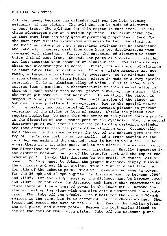
2 simply ride the moped at top speed for three or four miles to ensure the engine reaches its working temperature. Close the throttle partially. If the bike is apt to go faster, then the jet is too small and will have to be replaced with the original size jet. The fifth appearance is a glassy pearl between the electrode and ceramic insulator. This formation may be caused by a dirty air filter, a cutoff intake tube, no intake tube, or no dirt shield. The cylinder head is made of aluminum because this material has good heat abstraction. In order not to disturb the heat flow from the cylinder and the cylinder head, do not use a gasket or any seal between the cylinder and the cylinder head, because the cylinder will run too hot, causing seizure of the piston. CYLINDER INFO, MATERIALS, PORTS, AND CLEARANCES The cylinder can be made of aluminum or cast iron. The cylinder for this engine is cast iron. It has three advantages over an aluminum cylinder. The first advantage is that cast iron has very good dry-running properties. Secondly, the cast iron muffles vibrations and noise better than aluminum. The third advantage is that a cast-iron cylinder can be re-machined and re-honed. However, cast iron does have two disadvantages when compared with aluminum. First, the expansion of aluminum is about twice that of cast iron. Second the parts of a cast-iron cylinder are less accurate than those of an aluminum one. Now let s discuss those disadvantages in detail. First, the expansion of aluminum is about twice that of cast iron. If appropriate measures are not taken, a large piston clearance is necessary. So to minimize the piston clearance, the Laura Motoren piston is made of a very special material. It is an aluminum alloy of which 23% is silicon, which ensures less expansion. A characteristic of this special alloy is that is much harder than normal piston aluminum, thus insuring that the wrist pin bore will not wear out. In addition, the piston is shaped in a very special way. The configuration of the piston is adapted to every different temperature. Due to the special nature of this piston, use only original Laura Motoren pistons top prevent seizure of the piston or loss of power. Should the piston ever require replacing, be sure that the arrow on the piston bottom points in the direction of the exhaust port on the cylinder. Now, the second disadvantage of cast iron is that the ports of a cast iron cylinder are less accurate than the ports of an aluminum one. Occasionally this causes the distance between the top of the exhaust port and the top of the intake port to be too small. If a cross-section of the cylinder was made and then opened, this is how it would be. On both sides there is a transfer port, and in the middle, the exhaust port. The dimensions of the ports are very important. Equally important is the exhaust port. Should this distance be too small, it causes loss of power. In this case, to obtain the proper distance, simply dismount the cylinder and put it in a vise. Take a flat file and file the top side of the exhaust port. This will give an increase in power. For the 25mph and 30mph engines, the distance must be between inches and inches. For the 20mph engine, the distance must be between 0.90 inches and inches. Do not make the distance much larger than recommended because there will be a loss of power in the lower RPMs. TAKING APART THE CLUTCH Remove the starter leaf spring along with the dirt shield underneath the crankcase. Then take off the v- belt. The v-belt for the 25- and 30-mph engine is the same, but it is different for the 20mph engine. Then loosen and remove the nuts of the clutch. Remove the locking plate, the end plate, and clutch plate. Remove leaf spring fitted on one of the cams of the clutch plate. Take off the pressure plate. Flatten the tab washer. Take the special tool to block the clutch. Use a 17mm socket and loosen and remove the nut on the crankshaft. Fits the same special too with two of the small nuts and pull the clutch off the crankshaft. On the clutch hub is a coil spring filled with 31 steel balls. The diameter of this spring is smaller than the diameter of the hub on which the spring is fitted, meaning that the spring is prestressed on the hub. The coil springs for the M48 and M56 engines are not interchangeable. The M48 coil spring bears a rod marking. Not that the spring hub, the pressure plate, and the end plate are
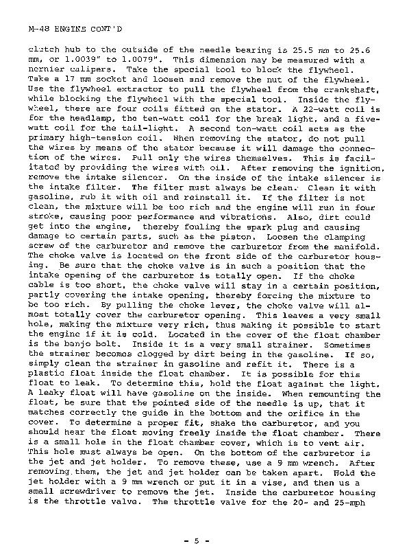
3 connected with the crankshaft. However, the clutch housing and the clutch lining are not connected to the crankshaft. The clutch lining is via the cams connected with the clutch housing. HOW THE CLUTCH MECHANISM WORKS Upon starting the engine, pull the start lever which bends the starter leaf spring, thereby engaging all parts, the end plate, clutch lining, and pressure plate. When beginning to pedal, the v-belt will move, forcing the clutch housing to turn. When the clutch housing rotates, the clutch plate will turn. When there is sufficient friction between the clutch plate, end plate, and pressure plate, then these parts will turn. Therefore, the spring hub will turn, and since this hub is connected with the crankshaft, the crankshaft will turn. This sequence of events starts the engine. By releasing the starter lever, the crankshaft will revolve, but the end plate, clutch lining, and pressure plate will not remain engaged, thus causing the engine not to move the moped. By opening the gas grip, revolutions of the crankshaft will increase. At a certain number of revolutions, the centrifugal forces of the steel balls in the spring will be sufficient to force the spring to the outside. When the spring moves to the outside, it will move along the sloping side of the spring hub, forcing it to the left, thereby pushing the pressure plate, clutch lining, and end plate together. If there is sufficient friction, the pressure plate and end plate rotate the clutch lining within them. Since the cutch lining is connected via the cam with the clutch housing, then the clutch housing will turn and the v-belt will move, thus propelling the moped. On top of the clutch housing is a plain steel washer on the crankshaft. On top of that washer is a disc washer with the concave side pointing away from the engine. This position is very important because, if the disc washer is reversed, the clutch will stick. On top of that disc washer is a smaller, plain steel washer. It is used only for the 25 and 30mph engines; it is not used for the 20mph engine. In the clutch housing is a needle bearing. On the engine side, there is a seal which is part of the bearing. On the other side is a separate seal. Should it ever be necessary to replace that needle bearing, press only on the side with the inscription, because that side is heat treated and it is thicker. Pressing on the other side will damage the needle bearing. Press the needle bearing into the housing, being sure that the distance from the inner side of the clutch hub to the outside of the needle bearing is 25.5mm to 25.6mm, or to This dimension may be measured with calipers. REMOVING THE FLYWHEEL/STATOR Take the special tool to block the flywheel. Take a 17mm socket and loosen and remove the nut of the flywheel. Use the flywheel extractor to pull the flywheel from the crankshaft while blocking the flywheel with the special tool. Inside the flywheel, there are four coils fitted on the stator. A 22-watt coil is for the headlamp, the ten-watt coil is for the brake light, and a 5watt coil for the tail light. A second 10-watt coil acts as the primary high-tension coil. When removing the stator, do not pull the wires by means of the stator because it will damage the connection of the wires. Pull only the wires themselves. This is facilitated by providing the wires with oil. CARB/INTAKE REMOVAL AND TROUBLESHOOTING After removing the ignition, remove the intake silencer. On the inside of the intake silencer is the intake filter. The filter must always be clean. Clean it with gasoline, rub it with oil, and reinstall it. If the filter is not clean, the mixture will be too rich and the engine will run in four stroke, causing poor performance and vibrations. Also, dirt could get into the engine, thereby fouling the spark plug and causing damaged to certain parts, such as the piston. Loosen the clamping screw of the carburetor and remove the carburetor from the manifold. The choke valve is located on the front side of the carburetor housing. Be sure that the choke valve is in such a position that the intake opening of the carburetor is totally open. If the choke cable is too short, the choke valve will stay in a certain position, partially covering the intake
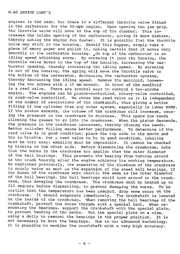
4 opening, thereby forcing the mixture to be too rich. By pulling the choke lever, the choke valve will almost totally cover the carburetor opening. This leaves a very small hole, making the mixture very rich, thus making it possible to start the engine if it is cold. Located in the cover of the float chamber is the banjo bolt. Inside it is a very small strainer. Sometimes the strainer becomes clogged by dirt in the gasoline. If so, simply clean the strainer in gasoline and refit it. There is a plastic float inside the chamber. It is possible that these plastic floats leak. To determine this, hold the float against the light. A leaky float will have gasoline on the inside. When remounting the float, be sure that the pointed side of the needle is up, that it matches correctly the guide n the bottom and the orifice in the cover. To determine a proper fit, shake the carburetor, and you should hear the float moving freely inside the float chamber. There is a small hole in the float chamber cover, which is to vent air. This hole must always be open. On the bottom of the carburetor is the jet and jet holder. To remove these, use a 9mm wrench. After removing them, the jet and jet holder can be taken apart. Hold the jet holder with a 9mm wrench or put it in a vise, then use a small screwdriver to remove the jet. Inside the carburetor housing is the throttle valve. The throttle valve for the 20- and 25mph engines is the same, but there is a different throttle valve fitted in the carburetor for the 30mph engine. Upon opening the gas grip, the throttle valve will move to the top of the chamber. This increases the intake opening of the carburetor, giving it more mixture, thereby making the engine run faster. It is possible that the throttle valve may stick in the housing. Should this happen, simply take a piece of emery paper and polish it, making certain that it moves very smoothly in the carburetor housing. On top of the carburetor is an idling speed adjusting screw. By screwing it into the housing, the throttle valve moves to the top of the housing, increasing the carburetor opening, thereby increasing idling speed. By screwing it out of the housing, the spring will move the throttle valve to the bottom of the carburetor, decreasing the carburetor opening and decreasing the idling speed. REED VALVE INFORMATION/CHECKING Remove the manifold, loosening the two screws with a 10mm wrench. In front of the manifold is a reed valve. There are several ways to control a two-stroke engine. The engines can be piston controlled, rotary valve controlled, or reed valve controlled. We chose the reed valve as it is independent of the number of revolutions of the crankshaft, thus giving a better filling of the cylinder than any other system, especially in lower RPMs. If the piston ascends, the volume of the crankcase will increase, causing the pressure in the crankcase to decrease. This opens the reeds allowing the gasses to go into the crankcase. When the piston descends, the pressure in the crankcase increases, thereby closing the reeds. Better cylinder filling means better performance. To determine if the reed valve is in good condition, place the top side in the mouth and try to breathe. For a reed valve to be in good condition inhaling must be very easy; exhaling must be impossible. It cannot be checked by blowing on the other side. SPLITTING THE CASE/CRANKSHAFT INFO Before dismounting the crankcase, note that the bores in the crankcase are smaller than the outer diameter of the ball bearings. This prevents the bearings from turning around in the crank housing after the engine achieves its working temperature. As mentioned previously, the expansion of the aluminum of the crankcase is nearly twice as much as the expansion of the steel ball bearings. If the bores of the of crankcase were exactly the same as the outer diameter of the ball bearings, the ball bearings would turn around in the crankcase, thus damaging the crankcase. The crankcase must be heated up to 212 degrees before dismantling, to prevent damaging the bores. To be certain that the temperature has been reached, drop some water on the crankcase. When removing the ball bearings of the crankshaft, protect the screw threads with a special tool. When remounting the bearings, support the crankshaft with the special plate to prevent the bending of the webs. Put the special plate on a vise, using a dolly to
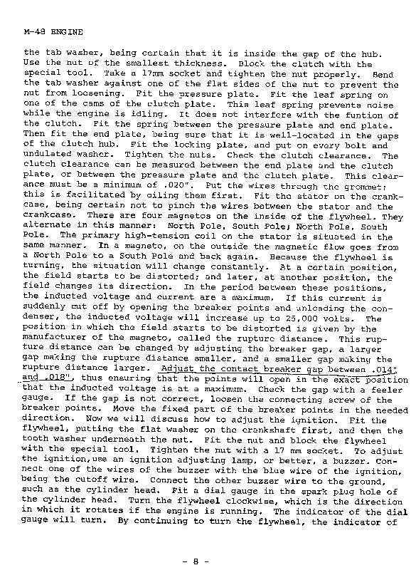
5 remount the bearings in the proper position. It is not necessary to heat the bearings. Due to our advanced technology, it is possible to machine the crankshaft with a very high accuracy. The bore for the big-end bearing is honed with a tolerance of a maximum 0.003mm, or inches, and is the size of the deviation is a maximum of 0.001mm or inches. This accuracy cannot be realized by grinding the bore. The described manner of machining the connecting rod allows a very small radial clearance of the big-end bearings, which is 0.12mm or inches. Previously, grinding was the accepted machining of the bore. Since Laura Motoren began honing the bore, we have manufactured nearly 800,000 crankshafts and haven t had even one damaged big end bearing. Because the accuracy is so high and the clearance is so small, it is virtually impossible to replace a connecting rod since very highly refined instruments and tools are required. Should it ever be necessary to replace a connecting rod, replace the complete crankshaft? Should you have to replace the oil seals, use the special tools to be certain that the seals will not be damaged and that they will be fitted in the right position. To determine the need to replace the oil seals, remove the carburetor from the engine. Put the piston in top dead center and be sure all ports in the cylinder are closed. Then blow some smoke in the manifold. If the smoke leaks out of the seals, then obviously they must be replaced. The first symptom of a leak is that the engine is very hard to start. Secondly, if it starts, it will idle at very high RPMs. REASSEMBLING THE ENGINE Now that the engine is completely dismantled, let s discuss rebuilding the engine. Begin with the crankcase part on the clutch side. In this part are two dowel pins which provide a fixed base for the gasket. To allow the gasket to stick, put some oil in the crankcase surface. Put the other crankshaft with the clutch side into this crankcase part. Take the other crankcase part and fit both the crankcase parts together. Before reassembling the crankcase parts, they must be heated up to 212 degrees. Tighten the six crankcase screws. After the crankcase has cooled off and shrunk sufficiently, re-tighten the screws. Cut the crankcase gasket so that it matches exactly the crankcase surface on both sides. Fit the cylinder base gasket. Do be certain it is fitted in the right way, not covering the ports, as this would cause a loss of power. The cylinder bore is tapered, which allows one to pinch the piston rings with the fingers. Slide the cylinder over the piston. Be sure that the piston ring gap is properly located around the little pegs in the piston grooves. Fit the cylinder head, never using a gasket or any seal. Then put a flat washer and a spring washer underneath the cylinder head nuts. Fit the cylinder head nut and tighten them crosswise. Torque the nuts with 8.7 toot pounds. Before fitting the clutch housing on the crankshaft, use the special tool that prevents the oil seal from being damaged while fitting it. Fit the plain steel washer, being certain that is well centered on the crankshaft. Fit the disc washer on the concave side pointing away from the engine. For the 25 and 30mph engines, use the second smaller plain steel washer and fit it on the crankshaft. Fit the spring hub on the crankshaft. Fit the tab washer, being certain that it is inside the gap of the hub. Use the nut of the smaller thickness. Block the clutch with the special tool Take a 17mm socket and tighten the nut properly. Bend the tab washer against of the of the flat sides of the nut to prevent the nut from loosening. Fit the pressure plate. Fit the leaf spring on one of the cams of the cutch plate. This leaf spring prevents noise while the engine is idling. It does not interfere with the function of the clutch. Fit the spring between the pressure plate and end plate. Then fit the end plate, being sure that it is well-located in the gaps of the clutch hub. Fir the locking plate, and put on every bolt and undulated washer. Tighten the nuts. Check the clutch clearance. The clutch clearance can be measured between the end plate and the clutch plate, or between the pressure plate and the clutch plate. This clearance must be a minimum of Put the wires through the grommet; this is facilitated by oiling them first. Fit the stator on the crankcase, being certain not to pinch the wires between the stator and the crankcase. There are four magnets on the inside of the flywheel. They alternate in this manner: north pole, south pole; north pole, south pole. The primary high-tension coil on the stator is situated in the same manner. In a magneto, on the outside the magnetic flow goes from a north pole to
6 a south pole and back again. Because the flywheel is turning, the situation will change constantly. At a certain position, the field starts to be distorted, and later, at another position, the field changes its direction. In the period between these positions, the inducted voltage and current are a maximum. If this current is suddenly cut off by opening the breaker points and unloading the condenser, the inducted voltage will increase up to 25,000 volts. The position in which the field starts to be distorted is given by the manufacturer of the magneto, called the rupture distance. This rupture distance can be changed by adjusting the breaker gap, a larger gap making the rupture distance smaller, and a smaller gap making the rupture distance larger. Adjust the contact breaker gap between 0.14 inches and 0.18 inches, thus ensuring that the points will open in the exact same position that the inducted voltage is at a maximum. Check the gap with a feeler gauge. If the gap is not correct, loosen the connecting screw of the breaker points. Move the fixed part of the breaker points in the needed direction. SETTING THE TIMING Now we will discuss how to adjust the ignition. The contact breaker gap is between 0.14 and 0.18 inches. Fit the flywheel, putting the flat washer on the crankshaft first, then the tooth washer underneath the nut. Fit the nut and block the flywheel with the special tool. Tighten the nut with a 17mm socket. To adjust the ignition, use an ignition adjusting lamp, or better, a buzzer. Connect one of the wires of the buzzer with the blue wire of the ignition, being the cutoff wire. Connect the other buzzer wire to the ground, such as the cylinder head. Fit a dial gauge in the spark plug hole of the cylinder head. Turn the flywheel clockwise, which is the direction in which it rotates if the engine is running. The indicator of the dial gauge will turn. By continuing to turn the flywheel, the indicator of the dial gauge will stop and change its direction. At this point, the piston is in top dead center. Then turn the flywheel counterclockwise until the sound of the buzzer changes. This is the moment the breaker points close, which is the moment the spark ignites. The advance can be measured by counting the turns of the dial gauge. By counting the turns, it can be determined what the distance is between the bottom of the piston and top dead center at the moment the spark ignites. Then the advance has to be adjusted. It must be between and 0.87 inches for all engines. The advance can be changed by turning the stator after loosening the three connecting screws. If the distance is too large, which means the spark is igniting too early then turn the stator clockwise. If this distance is too small, which means the spark is igniting too late, turn the stator counterclockwise. Then take a new gasket and fit it on the reed valve, then fit the reed valve in the crankcase. Take another new gasket and fit it on the manifold Fit the manifold on the housing, using the two screws. Tighten the screws to be sure that the manifold is sealed. Fit the carburetor on the manifold and tighten the clamping screw. Fit the filter with the rubber seal, clamping on the intake silencer. Be sure to use the rubber seal. Before fitting the starter leaf spring and the dirt shield, fit the v-belt on the clutch housing. Before fitting the dirt shield, be sure that the little distance bushings are in the dirt shield. This prevents damage of the dirt shield. The dirt shield is attached with three screws. Two of them are longer than the third. Be certain that the two longer screws are used on the side where the starter leaf spring is located. Check the clearance between the starter leaf spring and the copper thrust piece. This clearance should be between 0.20 and If this clearance is too small, bend the starter leaf spring while it is fitted on the crankcase. But if this distance is too large, remove the starter leaf spring, put it in a vice, bending it in such a way that the clearance is what it should be. Provide the thrust piece with grease of any kind. Never let the moped be driven without the dirt shield. Fit the spark plug and connect the high-tension lead. Now the engine is ready to be used.
7
8
9
10
11
12
13
14
15
16 Batavus M48 Tech Notes Downloaded from: Project Moped Manual Originally posted at:
13. CRANKCASE/CRANKSHAFT/BALANCER/PISTON/CYLINDER
 13. CRANKCASE/CRANKSHAFT/BALANCER/PISTON/CYLINDER COMPONENT LOCATION 13-2 SERVICE INFORMATION 13-3 TROUBLESHOOTING 13-4 CRANKCASE SEPARATION 13-5 CRANKSHAFT 13-7 MAIN JOURNAL BEARING 13-9 CRANKPIN BEARING
ENGINE REMOVAL AND REINSTALLATION 3-1 ENGINE REMOVAL 3-1 ENGINE REINSTALLATION
 ENGINE CONTENTS ENGINE REMOVAL AND REINSTALLATION 3-1 ENGINE REMOVAL 3-1 ENGINE REINSTALLATION 3-5 ENGINE DISASSEMBLY 3-6 ENGINE COMPONENTS INSPECTION AND SERVICING 3-15 BEARINGS 3-15 OIL SEALS 3-15 CRANKSHAFT
CONTENTS. Special tools Technical Data. 7 Clutch, Automatic plate (120mm diameter) 8
 8") 1 CONTENTS Special tools.. 3-6 Technical Data. 7 Clutch, Automatic plate (120mm diameter) 8 Description, Operation 8 Clutch, Automatic plate (120mm diameter) with variable speed transmission. 9 Description,
1 CONTENTS Special tools.. 3-6 Technical Data. 7 Clutch, Automatic plate (120mm diameter) 8 Description, Operation 8 Clutch, Automatic plate (120mm diameter) with variable speed transmission. 9 Description,
CHAPTER 6 IGNITION SYSTEM
 CHAPTER 6 CHAPTER 6 IGNITION SYSTEM CONTENTS PAGE Faraday s Law 02 The magneto System 04 Dynamo/Alternator System 06 Distributor 08 Electronic System 10 Spark Plugs 12 IGNITION SYSTEM Faraday s Law The
COLT 2310, 2510, AND 2712 COM PACT TRACTORS CHAPTER 9 TROUBLESHOOTING AND ANALYSIS
 COLT 2310, 2510, AND 2712 COM PACT TRACTORS CHAPTER 9 TROUBLESHOOTING AND ANALYSIS 9-A-1 UPON RECEIVING ANENGINE FORRE- PAIR. Learn the history of the unit from the customer. While the customer is present
SPECIFICATIONS TEST AND ADJUSTMENT SPECIFICATIONS SPECIFICATIONS ENGINE FD620D, K SERIES
 TEST AND ADJUSTMENT Engine Oil Pressure Sensor Activates............................... 98 kpa (14.2 psi) Oil Pressure While Cranking (Minimum).......................... 28 kpa (4 psi) Oil Pressure.....................................
TILLOTSON LTD., CLASH INDUSTRIAL ESTATE, TRALEE, CO. KERRY, IRELAND PHONE: FAX:
 TILLOTSON LTD., CLASH INDUSTRIAL ESTATE, TRALEE, CO. KERRY, IRELAND PHONE: +353 66 7121911 FAX: +353 66 7124503 e-mail: sales@tillotson.ie HR SERIES SERVICE MANUAL INTRODUCTION Tillotson has developed
WORKSHOP MANUAL. Chainsaw GS35 GS350 MT350 MT3500
 WORKSHOP MANUAL Chainsaw GS35 GS350 MT350 MT3500 General failures analysis Suggested tools I. Emak tool kit II. Compression tester: to check thermal group III. Electronic tachometer: for 2 and 4 stroke
Operation and Maintenance Instructions for the RAPTOR 178
 WWW.SKYTOY.COM Operation and Maintenance Instructions for the RAPTOR 178 See www.skytoy.com for updates and service bulletins. 2/1/2011 1. Parts Schematic:... 3 2. Muffler Assembly Diagram:... 4 3. Muffler
MODELS 3100,3130,3160, 1300, 1330,1360 EXHAUST SYSTEM
 MODELS 3100,3130,3160, 1300, 1330,1360 EXHAUST SYSTEM WALBRO CARBURETOR "WA" SERIES MUFFLER REMOVAL CARBURETOR REMOVAL The muffler assembly should beremoved periodically to inspect for excessive carbon
SPECIFICATIONS TEST AND ADJUSTMENT SPECIFICATIONS SPECIFICATIONS ENGINE FD620D, K SERIES
 ENGINE FD620D, K SERIES SPECIFICATIONS SPECIFICATIONS TEST AND ADJUSTMENT SPECIFICATIONS Engine Oil Pressure Sensor Activates............................... 98 kpa (14.2 psi) Oil Pressure While Cranking
20.Cylinder Block. Cylinder Block A: REMOVAL ME(H4DOTC)-63 ST CRANKSHAFT STOPPER
-63 ST CRANKSHAFT STOPPER") Cylinder Block MECHANICAL 20.Cylinder Block A: REMOVAL Before conducting this procedure, drain engine oil completely. 1) Remove the intake manifold. 2)
Cylinder Block MECHANICAL 20.Cylinder Block A: REMOVAL Before conducting this procedure, drain engine oil completely. 1) Remove the intake manifold. 2)
AN EXPLANATION OF CIRCUITS CARTER YH HORIZONTAL CLIMATIC CONTROL CARBURETER
 AN EXPLANATION OF CIRCUITS CARTER YH HORIZONTAL CLIMATIC CONTROL CARBURETER The Carter Model YH carbureter may be compared with a Carter YF downdraft carbureter with the circuits rearranged to operate
5. FUEL SYSTEM FUEL SYSTEM 5-0
 5 FUEL SYSTEM 5-0 SERVICE INFORMATION GENERAL INSTRUCTIONS SERVICE INFORMATION...5-1 CARBURETOR INSTALLATION...5-9 TROUBLESHOOTING...5-1 PILOT SCREW ADJUSTMENT...5-10 CARBURETOR REMOVAL...5-2 AUTO BYSTARTER...5-3
CARTER DOWNDRAFT CARBURETOR Terraplane All Models. Technical Information
 CARTER DOWNDRAFT CARBURETOR 1934 Terraplane All Models Technical Information . Carter W-1 Downdraft Carburetors 1934 Terraplane Challenger, Model KS NOTE: Terraplane Models. Carburetor fitted with Anti-
Local Option 206 Rules Manual Section 1 General Rules 1. Only stock Briggs & Stratton LO206 # engine will be allowed in this class.
 Local Option 206 Rules Manual Section 1 General Rules 1. Only stock Briggs & Stratton LO206 # 124332-8201engine will be allowed in this class. o All parts will be stock unaltered Briggs & Stratton Animal
World Formula TECH MANUAL
 World Formula TECH MANUAL Section 1 General Rules 1. Only stock Briggs & Stratton World Formula Model # 124435-8101 will be used in this class except as provided in this Tech manual. All parts will be
7. FUEL SYSTEM ('04 - '05)
") 7. FUEL SYSTEM ('04 - '05) SYSTEM COMPONENTS 7-2 CARBURETOR DISASSEMBLY 7-81 SERVICE INFORMATION 7-3 CARBURETOR ASSEMBLY 7-14 TROUBLESHOOTING 7-4 CARBURETOR INSTALLATION 7-21 AIR CLEANER HOUSING 7-5 PILOT
7. FUEL SYSTEM ('04 - '05) SYSTEM COMPONENTS 7-2 CARBURETOR DISASSEMBLY 7-81 SERVICE INFORMATION 7-3 CARBURETOR ASSEMBLY 7-14 TROUBLESHOOTING 7-4 CARBURETOR INSTALLATION 7-21 AIR CLEANER HOUSING 7-5 PILOT
Super 1050 Chain Saw UT Page 1 of 16 Carburetor Chamber
 Super 1050 Chain Saw UT-10139 Page 1 of 16 Carburetor Chamber Super 1050 Chain Saw UT-10139 Page 2 of 16 Carburetor Chamber 1 58319A 1 RING- Retaining 2 592301 1 COVER- Air filter 3 A70326 1 NUT- Cover
Name Date. True-False. Multiple Choice
 Name Date True-False T F 1. Oil film thickness increases with an increase in oil temperature. T F 2. Displacement is the volume that a piston displaces in an engine when it travels from top dead center
DrVanos.com Stage II Installation Instructions. Tool rental is available with the purchase of a vanos kit *See website for more info*
 DrVanos.com Stage II Installation Instructions Special Tools Needed: Camshaft locking tool TDC Crank pin Sprocket turning tool Tool rental is available with the purchase of a vanos kit *See website for
ENGINE CONTENTS CAUTION
 ENGINE CONTENTS ENGINE REMOVAL AND REINSTALLATION 3- ENGINE REMOVAL 3- ENGINE REINSTALLATION 3-7 ENGINE DISASSEMBLY 3-9 STARTER MOTER 3-9 THERMOSTAT 3-9 ND AIR VALVE 3-0 CYLINDER HEAD COVER 3-0 PISTON
SERVICE DATA CHAIN SAW CS-450. (Serial number : and after) CONTENTS INTRODUCTION. Reference No B-01 REVISED: ISSUED:
 CONTENTS INTRODUCTION. Reference No B-01 REVISED: ISSUED:") 01-45B-01 1 0 SERVICE DATA CHAIN SAW (Serial number : 36000001 and after) INTRODUCTION We are constantly working on technical improvement of our products. For this reason, technical data, equipment and
01-45B-01 1 0 SERVICE DATA CHAIN SAW (Serial number : 36000001 and after) INTRODUCTION We are constantly working on technical improvement of our products. For this reason, technical data, equipment and
9.7 Replacement of the compressed air distributor
 9.6.6 9.6.7 screw in the bolt and to increase unscrew the bolt. For a complete rotation of the bolt, the variation is of 1mm. After measuring the pointer position and the compensatory adjustment screw
Repair Manual 11/99 PS-34. Page 1
 Repair Manual /99 PS-4 Page Table of contents Index Technical Data page Special tools 4 Repair instructions, general 0 Chain brake 6 0 Centrifugal clutch 8 0 Oil pump 9-04 Ignition system - 0 Starting
00-33A-01 CS-330T, CS-360T 1
 00-33A-01 CS-330T, CS-360T 1 0 INTRODUCTION We are constantly working on technical improvement of our products. For this reason, technical data, equipment and design are subject to change without notice.
ENG CRANKCASE AND REED VALVE. REED VALVE INSPECTION 1. Measure: 8 Valve stopper height 1 Out of specification Adjust stopper/replace valve stopper.
 CRANKCASE AND REED VALVE ENG REED VALVE INSPECTION. Measure: 8 Valve stopper height Out of specification Adjust stopper/replace valve stopper. Valve stopper height 6.0~6. mm(0.~0.5 in). Measure: 8 Reed
BOTTOM END SERVICE TOOLS SERVICE PRODUCTS ENGINE, CVT AND GEARBOX Subsection 10 (BOTTOM END)
") BOTTOM END SERVICE TOOLS Description Part Number Page CRANKCASE SUPPORT MAG/PTO... 529 036 031... 151 CRANKSHAFT LOCKING BOLT... 529 035 617... 154 DRIVE SHAFT OIL SEAL INSTALLER... 529 036 028... 143
BOTTOM END SERVICE TOOLS Description Part Number Page CRANKCASE SUPPORT MAG/PTO... 529 036 031... 151 CRANKSHAFT LOCKING BOLT... 529 035 617... 154 DRIVE SHAFT OIL SEAL INSTALLER... 529 036 028... 143
SERVICE DATA CHAIN SAW ECHO: CS-500ES STAGE MODEL. (Serial number : and after) CONTENTS INTRODUCTION
 CONTENTS INTRODUCTION") 01-50D-01 1 0 SERVICE DATA CHAIN SAW ECHO: STAGE MODEL (Serial number : 37000001 and after) INTRODUCTION We are constantly working on technical improvement of our products. For this reason, technical data,
01-50D-01 1 0 SERVICE DATA CHAIN SAW ECHO: STAGE MODEL (Serial number : 37000001 and after) INTRODUCTION We are constantly working on technical improvement of our products. For this reason, technical data,
SERVICE DATA GT-220ES SRM-220ES TRIMMER/BRUSHCUTTER. (Serial nember : and after) (Serial nember : and after) INDEX INTRODUCTION
 (Serial nember : and after) INDEX INTRODUCTION") 10-21P-02, 1 1 SERVICE DATA TRIMMER/BRUSHCUTTER INTRODUCTION We are constantly working on technical improvement of our products. For this reason, technical data, equipment and design are subject to change
10-21P-02, 1 1 SERVICE DATA TRIMMER/BRUSHCUTTER INTRODUCTION We are constantly working on technical improvement of our products. For this reason, technical data, equipment and design are subject to change
980 B Wheel Loader S/n 89P1 & Up Volume 1 of 2
 Caterpillar Service Manual 980 B Wheel Loader S/n 89P1 & Up Volume 1 of 2 Service Manual THIS IS A MANUAL PRODUCED BY JENSALES INC. WITHOUT THE AUTHORIZATION OF CATERPILLAR OR IT S SUCCESSORS. CATERPILLAR
3. INSPECTION/ADJUSTMENT
 3 SERVICE INFORMATION...3-0 FINAL REDUCTION GEAR OIL...3-7 MAINTENANCE SCHEDULE...3-2 DRIVE BELT...3-7 FUEL FILTER...3-3 BRAKE SHOE...3-8 THROTTLE OPERATION...3-3 BRAKE ADJUSTING NUT...3-8 AIR CLEANER...3-4
CARBURETOR SERVICE INFORMATION TROUBLESHOOTING THROTTLE VALVE DISASSEMBLY THROTTLE VALVE INSTALLATION...
 11 CARBURETOR SERVICE INFORMATION... 11-2 TROUBLESHOOTING... 11-2 THROTTLE VALVE DISASSEMBLY... 11-3 THROTTLE VALVE INSTALLATION... 11-4 CARBURETOR REMOVAL... 11-5 AUTO BYSTARTER... 11-6 FLOAT CHAMBER...
00-36A-04 CS-350T, CS-350TES, CS-350WES 1
 00-36A-04,, 1 0 INTRODUCTION We are constantly working on technical improvement of our products. For this reason, technical data, equipment and design are subject to change without notice. All specifications,
INDEX TECHNICAL SPECIFICATIONS 2 SPECIAL TOOLS 3-4 PERIODIC MAINTENANCE 5 LUBRICANTS 6 TROUBLESHOOTING 7-14 TIGHTENING TORQUE TABLE 15
 INDEX TECHNICAL SPECIFICATIONS 2 SPECIAL TOOLS 3-4 PERIODIC MAINTENANCE 5 LUBRICANTS 6 TROUBLESHOOTING 7-14 TIGHTENING TORQUE TABLE 15 ENGINE DISASSEMBLY 16-24 ENGINE REASSEMBLY 25-37 SPECIAL 3-SHOE CLUTCH
400 4x4 Euro MODEL NUMBER A2008IDG4BEUR (RED) MODEL NUMBER A2008IDG4BEUG (GREEN) MODEL NUMBER A2008IDG4BEUZ (CAT GREEN) MORE TO GO ON.
 MODEL NUMBER A2008IDG4BEUG (GREEN) MODEL NUMBER A2008IDG4BEUZ (CAT GREEN) MORE TO GO ON.") 2008 400 4x4 Euro Illustrated Parts Manual MODEL NUMBER A2008IDG4BEUR (RED) MODEL NUMBER A2008IDG4BEUG (GREEN) MODEL NUMBER A2008IDG4BEUZ (CAT GREEN) MORE TO GO ON. TM TABLE OF CONTENTS 2008 ATV 400 4x4
2008 400 4x4 Euro Illustrated Parts Manual MODEL NUMBER A2008IDG4BEUR (RED) MODEL NUMBER A2008IDG4BEUG (GREEN) MODEL NUMBER A2008IDG4BEUZ (CAT GREEN) MORE TO GO ON. TM TABLE OF CONTENTS 2008 ATV 400 4x4
Typical Install Instructions
 Typical Install Instructions Read & understand all steps of these instructions before beginning this installation. WEBER Conversion Kit, VW T-1/2, up to 1835cc 32 / 36 DFEV Weber Carburetor These instructions
~. a~' ~ ( I o~~~ 4-0. ~Sj~' AO~ i/~ CB1000C (ij)aon'da in-ib) ~ "" ~ ~!~~P. ~ J N m (6-12 kg-em,
aon'da in-ib) ~ ~ ~!~~P. ~ J N m (6-12 kg-em,") e V ~. a~' ~ I ~ J C t \"" 8.0- ( I o~~~ ~ "" ~ ~. ~!~~P. C8 0 & 0,-t. ~ CB1000C (ij)aon'da 0.6-1.2 N m (6-12 kg-em, 5-10 in-ib) 4-0 / 4.0-6.0 N m (40-60 kg-em, 35-52 in-i b) t$ "'07~ / c;:::/ j ~Sj~'
e V ~. a~' ~ I ~ J C t \"" 8.0- ( I o~~~ ~ "" ~ ~. ~!~~P. C8 0 & 0,-t. ~ CB1000C (ij)aon'da 0.6-1.2 N m (6-12 kg-em, 5-10 in-ib) 4-0 / 4.0-6.0 N m (40-60 kg-em, 35-52 in-i b) t$ "'07~ / c;:::/ j ~Sj~'
PIERBURG. Carburetor: 2E3
 PIERBURG Carburetor: 2E3 1 fast idle adjusting screw 2 throttle lever 3 fuel mixture adjusting screw 4 main body 5 idle cut off valve 6 stop screw 7 accelerator pump cover 8 diaphragm 9 spring 10 valve
Not for Reproduction ADVANCE PRODUCT SERVICE INFORMATION APSI NO: 101 DATE: AUGUST SERIES UTILITY ENGINE 130G00 OHV HORIZONTAL SHAFT
 ADVANCE PRODUCT SERVICE INFORMATION APSI NO: 101 DATE: AUGUST 2014 SUBJECT: MODELS: 950 SERIES UTILITY ENGINE 130G00 OHV HORIZONTAL SHAFT This APSI provides basic servicing information in advance of the
13. FUEL SYSTEM/CARBURETOR/
 13 FUEL SYSTEM/CARBURETOR/FUEL PUMP FUEL SYSTEM --------------------------------------------------------- 13-1 SCHEMATIC DRAWING ---------------------------------------------- 13-2 OPERATION OF CARBURETOR
Briggs & Stratton Animal TECH MANUAL Version 1.6 Section 1 General Rules cannot Section 2 Required Modifications Section 3 Allowable Modifications
 Briggs & Stratton Animal TECH MANUAL Version 1.6 updated 2/ 7 / 2011 Section 1 General Rules 1. Only stock Briggs & Stratton Animal # 124332-8201and 124332-8203 - 01engine will be allowed in this class.
Remove Air Cleaner Cover and. Filter
 Remove Air Cleaner Cover and Inspect paper filter for tears Foam pre-cleaner is washable if equipped Replace if necessary Filter Remove Trim Panel Pull throttle lever knob off Remove 3, 8mm screws Remove
SERVICE DATA. CS-310 (Serial number : ) (Serial number : ) CHAIN SAW 01-30A-00 CS CONTENTS INTRODUCTION
 (Serial number : ) CHAIN SAW 01-30A-00 CS CONTENTS INTRODUCTION") 01-30A-00 CS-310 1 0 SERVICE DATA CHAIN SAW CS-310 (Serial number : 11000001-11999999) (Serial number : 12000001-12999999) INTRODUCTION We are constantly working on technical improvement of our products.
01-30A-00 CS-310 1 0 SERVICE DATA CHAIN SAW CS-310 (Serial number : 11000001-11999999) (Serial number : 12000001-12999999) INTRODUCTION We are constantly working on technical improvement of our products.
Performer Series Carburetor Rebuild Kit Catalog #1477 Models
 Please read these instructions carefully before attempting to rebuild your carburetor. Make sure to refer to your carburetor Owner s Manual for further information if need be. If you have any questions
7. CYLINDER HEAD/VALVES
 7 7 7-0 SERVICE INFORMATION...7-1 CYLINDER HEAD DISASSEMBLY...7-7 TROUBLESHOOTING...7-2 CYLINDER HEAD ASSEMBLY...7-8 CAMSHAFT REMOVAL...7-3 CYLINDER HEAD INSTALLATION...7-8 CYLINDER HEAD REMOVAL...7-5
Bthird, or power stroke by the expanding gases. As the
 third, or power stroke by the expanding gases. As the piston reaches DC it enters the fourth cycle. The exhaust valve opens and the piston rises forcing burned gases from the combustion chamber in what
INDEX INTRODUCTION. Reference No L-01 REVISED:
 12-21L-01 1 1 INTRODUCTION We are constantly working on technical improvement of our products. For this reason, technical data, equipment and design are subject to change without notice. All specifications
1 Green Pressure Regulator Spring Automatic transmissions operate at temperatures between 150ºF and
 Installation Instructions for 603107 Valve Body Kit C-4 1970 & Later Tools Required Speed Handle or Ratchet 3/8 Drive 1/2 Socket 3/8 Drive 7/16 Socket 3/8 Drive 5/16 Socket 3/8 Drive Small Screwdriver
Sherco Engine Teardown and Assembly Manual
 Sherco Engine Teardown This Manual is provided as a guide for: Removing the engine from the frame Splitting the cases Complete Disassembly of the engine Reassembly of the engine Reinstallation back in
FUEL SYSTEM CIRCUIT D'ESSENCE KRAFTSTOFFSYSTEM
 CIRCUIT D'ESSENCE KRAFTSTOFFSYSTEM 41 FUEL SYSTEM SERVICE INFORMATION TROUBLESHOOTING FUEL TANK AIR CLEANER CARBURETOR REMOVAL VACUUM CHAMBER FLOAT CHAMBER 4-1 PILOT SCREW 4-2 CARBURETOR SEPARATION 4-3
INTRODUCTION. Reference No S-01 REVISED:
 10-21S-01 GT-225, SRM-225 1 1 INTRODUCTION We are constantly working on technical improvement of our products. For this reason, technical data, equipment and design are subject to change without notice.
TECH INFORMATION EMPI D Performance 2-Barrel Carburetor
 TECH INFORMATION EMPI D Performance 2-Barrel Carburetor The New EMPI D 2-Barrel Performance Carburetor.Built specifically for the VW Aftermarket. With all the features that you have asked for More Progression
400 2x4/4x4 EFT SHARE OUR PASSION ṬM
 SHARE OUR PASSION ṬM 400 2x4/4x4 EFT Model Number A2009IDG2BETR (Red - 2x4) Model Number A2009IDG2BETZ (Cat Green - 2x4) Model Number A2009IDG4BETR (Red - 4x4) Model Number A2009IDG4BETG (Green - 4x4)
SECTION 4 - FUEL SYSTEMS AND CARBURETION
 SECTION - FUEL SYSTEMS AND CARBURETION FUEL SYSTEMS - - - - - - - - - - - - - - - - - - - - - - - - - - - - - - - - - - - - - - - - - - - - - - - - - - - - - - - - - - - - - -62 FUEL PUMP - - - - - - -
SERVICE DATA CHAIN SAW ECHO: CS-280WES STAGE MODEL. (Serial number : and after) CONTENTS INTRODUCTION. Reference No B-00 ISSUED:
 CONTENTS INTRODUCTION. Reference No B-00 ISSUED:") 00-27B-00 1 0 SERVICE DATA CHAIN SAW ECHO: STAGE MODEL (Serial number : 37000001 and after) INTRODUCTION We are constantly working on technical improvement of our products. For this reason, technical data,
00-27B-00 1 0 SERVICE DATA CHAIN SAW ECHO: STAGE MODEL (Serial number : 37000001 and after) INTRODUCTION We are constantly working on technical improvement of our products. For this reason, technical data,
01-36D-02 CS INTRODUCTION. Reference No D-02 ISSUED:
 01-36D-02 CS-370 1 0 INTRODUCTION We are constantly working on technical improvement of our products. For this reason, technical data, equipment and design are subject to change without notice. All specifications,
HIRTH 3203 Carburated - 65 hp
 HIRTH 3203 Carburated - 65 hp 2706-65Hp engine shown with fan cooling HIRTH s most popular engine. The 3203 produces more horsepower and torque per pound than any other engine in its power class. Hirth
FUEL SYSTEM/CARBURETOR/FUEL PUMP
 13 FUEL SYSTEM/CARBURETOR/FUEL PUMP FUEL SYSTEM-------------------------------------------------------------------------------------13-1 SCHEMATIC DRAWING-------------------------------------------------------------------------13-2
6. Cylinder Block SERVICE PROCEDURE A: REMOVAL 1. RELATED PARTS
 SERVICE PROCEDURE [W6A1] 2-3a A: REMOVAL 1. RELATED PARTS 1) Remove timing belt, camshaft sprockets and related parts. 2) Remove cylinder heads. 3) Remove
SERVICE DATA CHAIN SAW ECHO: CS-352ES STAGE MODEL. (Serial number : and after) CONTENTS INTRODUCTION
 CONTENTS INTRODUCTION") 01-34D-01 1 0 SERVICE DATA CHAIN SAW ECHO: STAGE MODEL (Serial number : 37000001 and after) INTRODUCTION We are constantly working on technical improvement of our products. For this reason, technical data,
01-34D-01 1 0 SERVICE DATA CHAIN SAW ECHO: STAGE MODEL (Serial number : 37000001 and after) INTRODUCTION We are constantly working on technical improvement of our products. For this reason, technical data,
WORKSHOP MANUAL. 63,4 cm³ chainsaws
 WORKSHOP MANUAL General failures analysis Suggested tools I. Emak tool kit II. Compression tester: to check thermal group III. Electronic tachometer: for 2 and 4 stroke engines, measurement range from
SMALL ENGINES II. Leader s Resource
 SMALL ENGINES II Leader s Resource This project manual is a joint effort of the P.E.I. 4-H Council and the P.E.I. Department of Agriculture reprinted 2010 This is just a guide for leaders to follow. You
Service Instruction ENGINE COMPONENTS, INC.
 Title: Service Instruction S.I. No.: 89-5-1 Page: 1 of 5 Issued: 05/05/89 Revision: 1 (09/01/01) Technical Portions of FAA DER Approved. FAILURE OF ENGINE TO START 27 points 1. Lack of fuel 2. Ignition
ATV 300 DVX CAT GREEN (A2011KSF2BUSZ) Page 1 of 56 AIR INTAKE ASSEMBLY
 Page 1 of 56 AIR INTAKE ASSEMBLY") 2011 ATV 300 DVX CAT GREEN (A2011KSF2BUSZ) Page 1 of 56 AIR INTAKE ASSEMBLY 2011 ATV 300 DVX CAT GREEN (A2011KSF2BUSZ) Page 2 of 56 AIR INTAKE ASSEMBLY Ref # Part Number Qty S/P/F Description 1 3303-705
2011 ATV 300 DVX CAT GREEN (A2011KSF2BUSZ) Page 1 of 56 AIR INTAKE ASSEMBLY 2011 ATV 300 DVX CAT GREEN (A2011KSF2BUSZ) Page 2 of 56 AIR INTAKE ASSEMBLY Ref # Part Number Qty S/P/F Description 1 3303-705
SOHC ENGINE MECHANICAL
 SECTION 1B SOHC ENGINE MECHANICAL CAUTION: Disconnect the negative battery cable before removing or installing any electrical unit or when a tool or equipment could easily come in contact with exposed
Super EZ Chain Saw UT Page 1 of 18 Tools And Accessories
 Super EZ Chain Saw UT-10440 Page 1 of 18 Tools And Accessories Super EZ Chain Saw UT-10440 Page 2 of 18 Tools And Accessories 24299 24299 ANVIL- Crankshaft installation 24304 24304 BIT- #2 pozidrive 24295
TECHNICAL DATA. COMPRESSION RATUI 9,5/1 WEIGHT ready to fly CONSUMPTION at 5400RPM 5,6litres/h POWER at 6200RPM
 VICTOR 1 SUPER This handbook aims to bring to the attention of key technical, functional and maintenance of your motor VICTOR 1. Read carefully the following pages, will be synonymous with safety, reliability
Kid Sprint Engine Rules Briggs World Formula
 Kid Sprint Engine Rules Briggs World Formula 2017 Jr Sprint Engine Rules Briggs World Formula effective 2/1/2017. All parts must bebriggs & Stratton factory production parts unless otherwise noted in these
X4 (GREEN) (A2000ATF2AUSG) Page 1 of 80 AIR INTAKE ASSEMBLY
 (A2000ATF2AUSG) Page 1 of 80 AIR INTAKE ASSEMBLY") 2000 300 2X4 (GREEN) (A2000ATF2AUSG) Page 1 of 80 AIR INTAKE ASSEMBLY 2000 300 2X4 (GREEN) (A2000ATF2AUSG) Page 2 of 80 AIR INTAKE ASSEMBLY Ref # Part Number Qty S/P/F Description 1 3570-001 1 /P Intake,
2000 300 2X4 (GREEN) (A2000ATF2AUSG) Page 1 of 80 AIR INTAKE ASSEMBLY 2000 300 2X4 (GREEN) (A2000ATF2AUSG) Page 2 of 80 AIR INTAKE ASSEMBLY Ref # Part Number Qty S/P/F Description 1 3570-001 1 /P Intake,
RIGHT LEFT. Fig. 9. Fig. 10. Page.33
 Remark : The coupling sleeve of the magneto is installed with the marking from the rubber part facing the magneto gear. 9.4.3.6 Carefully remove the magneto from the engine ; screw the nut of the coupling
1950 Pacemaker. Specifications & Adjustments
 Specifications & Adjustments Specifications & Adjustments ENGINE: Valve Arrangement Bore and Stroke Piston Displacement Maximum Torque Horsepower Actual Taxable Compression Ratio: Cast Iron Head (Std.)
10-25J-00 SRM-261T 1 INTRODUCTION. Reference No J-00 ISSUED:
 10-25J-00 SRM-261T 1 1 INTRODUCTION We are constantly working on technical improvement of our products. For this reason, technical data, equipment and design are subject to change without notice. All specifications
Version 1.4 Operating instructions Czech Republic
 Version 1.4 Operating instructions Czech Republic Please check updates of operating instructions at www.rotomotor.cz, that your engine has still the best care. (can happen important changes that will lead
5. FUEL SYSTEM 5-0 FUEL SYSTEM MXU 250R/300R
 5 FUEL SYSTEM 5 SERVICE INFORMATION------------------------------------------------ 5-2 TROUBLESHOOTING----------------------------------------------------- 5-3 FUEL TANK -----------------------------------------------------------------
TILLOTSON LTD., CLASH INDUSTRIAL ESTATE, TRALEE, CO. KERRY, IRELAND PHONE: FAX:
 TILLOTSON LTD., CLASH INDUSTRIAL ESTATE, TRALEE, CO. KERRY, IRELAND PHONE: +353 66 7121911 FAX: +353 66 7124503 e-mail: sales@tillotson.ie SERIES SERVICE MANUAL INTRODUCTION The gasoline engine industry
Engine Construction and Principles of Operation
 Ch. 4 Engine Construction and Principles of Operation Gasoline Engine A gasoline fueled engine is a mechanism designed to transform chemical energy into mechanical energy It is an internal combustion engine.
I. TWO-STROKE MECHANICAL EN- GINE PARTS
 I. TWO-STROKE MECHANICAL EN- GINE PARTS 1. UNIBLOCK ENGINES (AV520-600-750-125) a) INTRODUCTION Fig. 1 shows the short block. Fig. 2 shows an exploded view of the engine. As may be seen the momoblock is
Husqvarna Hedgetrimmers 325HS/ 325HE/ 325HDA. Workshop manual
 Husqvarna Hedgetrimmers 325HS/ 325HE/ 325HDA Workshop manual 101 90 73-26 2 Workshop Manual Hedge trimmers Supplement for models 325HS, 325HE,325HDA Contents 1. Starter 5 2. Ignition system 7 3. Fuel system
Super EZ Chain Saw UT Page 1 of 19 Carburetor
 Super EZ Chain Saw UT-10580 Page 1 of 19 Carburetor Super EZ Chain Saw UT-10580 Page 2 of 19 Carburetor 1 93203A 1 /P Repair Kit Includes items 1-16. 2 93203A 1 /P Repair Kit Includes items 1-16. 3 93203A
Small Engine Parts. 306A Gas Chain Page Saw 1 of 10 Carburetor & Choke Assembl
 Small Engine Parts 306A Gas Chain Page Saw 1 of 10 Carburetor & Choke Assembl 1 530001686 2 Screw 2 530010049 1 Crankcase 3 530019022 1 Gasket - Carburetor - Adapter to C/Case Included in Gasket Kit 4
DVX 300 Euro. Model Number A2012KSF2BEUK SHARE OUR PASSION.
 ATV 2012ATV Illustrated Parts Manual DVX 300 Euro Model Number A2012KSF2BEUK TM SHARE OUR PASSION. TABLE OF CONTENTS 2012 ATV DVX 300 Euro (Model No. A2012KSF2BEUK) BODY PANEL AND HEADLIGHT ASSEMBLY...
Carburetor Instructions
 Carburetor Instructions for HUDSON SUPER SIX ESSEX SIX CYLINDER Hudson Motor Car Co. DETROIT, U.S.A. Carburetor The carburetor is a device for metering correct amounts of fuel and air for the various
90 Utility Model Number A2013KUB2BUSZ SHARE OUR PASSION.
 2013 90 Utility Model Number A2013KUB2BUSZ TM SHARE OUR PASSION. TABLE OF CONTENTS 2013 ATV 90 (Model No. A2013KUB2BUSZ) BODY PANEL AND HEADLIGHT ASSEMBLY... 1 FRONT AND REAR RACK ASSEMBLY... 2 FRAME AND
2018 Junior Sprint Rules
 2018 KidSprint Engine Rules Briggs World Formula 2018B All parts must be Briggs & Stratton factory production parts unless otherwise noted in these rules. No machining, polishing or alteration of any parts
Figure 1. - Cylinder / Cylinder Head
 Page 1 of 42 Figure 1. - Cylinder / Cylinder Head Figure 1. Cylinder / Cylinder Head 1 11111-STG-00 Cylinder comp 1 2 11121-STG-00 Head comp, cylinder 1 3 11127-CHP-00 Nut, cylinder head 1 4 11141-ROA-00
WEBER CARBURETOR TROUBLESHOOTING GUIDE
 This guide is to help pinpoint problems by diagnosing engine symptoms associated with specific vehicle operating conditions. The chart will guide you step by step to help correct these problems. For successful
SMF / DSF / DTF SMF / DSF / DTF 200
 2006 SMF / DSF / DTF 200 1 The drawings in this parts book have been scaled so that parts can be easily recognized. 1 CYLINDER ASSY 2 CYLINDER ASSY Ref # Part # Description 1 410 0001A CYLINDER HEAD COVER
Rekluse Motor Sports, Inc. The z-start Clutch. Husaberg ( )
") Rekluse Motor Sports, Inc. The z-start Clutch Husaberg (1989-2003) Installation Guide Copyright 2002-2004 Rekluse Motor Sports z-start Revision 3.000 RMS125 Husaberg 89-03 191-225 Manual Revision: 012805
Rekluse Motor Sports, Inc. The z-start Clutch Husaberg (1989-2003) Installation Guide Copyright 2002-2004 Rekluse Motor Sports z-start Revision 3.000 RMS125 Husaberg 89-03 191-225 Manual Revision: 012805
1.6L 4-CYL - VIN [E]
![1.6L 4-CYL - VIN [E]](/thumbs/81/84172348.jpg "1.6L 4-CYL - VIN [E]") 1.6L 4-CYL - VIN [E] 1993 Nissan Sentra 1993 NISSAN ENGINES 1.6L 4-Cylinder NX, Sentra * PLEASE READ THIS FIRST * NOTE: For engine repair procedures not covered in this article, see ENGINE OVERHAUL PROCEDURES
1.6L 4-CYL - VIN [E] 1993 Nissan Sentra 1993 NISSAN ENGINES 1.6L 4-Cylinder NX, Sentra * PLEASE READ THIS FIRST * NOTE: For engine repair procedures not covered in this article, see ENGINE OVERHAUL PROCEDURES
REF. NO. DESCRIPTION TOP COWLING 2 MOLDING, AIR DUCT 3 RIVET 4 SEAL 5 HOLDER, CLAMP BAND 6 BOLT, WITH WASHER 7 HOOK
 SUZHOU ALLPASS MACHINERY CO.,LTD Add:No.85,Jishui Road,Jinfeng Industrial Park,Mudu Town,Suzhou 215102,Jiangsu,P.R.China T15 SPARE PARTS EXPLODED DRAWING FIG. 1 1 TOP COWLING TOP COWLING 2 MOLDING, AIR
SERVICE DATA POWER PRUNER ECHO: PPF-300ES ECHO: PPT-300ES. (Serial number : and after) CONTENTS INTRODUCTION
 CONTENTS INTRODUCTION") 17-28A-00, 1 1 SERVICE DATA We are constantly working on technical improvement of our products. For this reason, technical data, equipment and design are subject to change without notice. All specifications
17-28A-00, 1 1 SERVICE DATA We are constantly working on technical improvement of our products. For this reason, technical data, equipment and design are subject to change without notice. All specifications
Illustrated Parts List
 FORM MS 9492 4C 1/2002 REPLACES FORM MS 9492 3C 6/2001 FILE IN SECT. 2 OF SERVICE MANUAL 422400 Illustrated Parts List Model Series 422400 TYPE NUMBERS 0728 through 4888. For Use On Engines Built Before
BRIDGESTONE M 1)RCYCLES TUNING UP
RCYCLES TUNING UP") BRIDGESTONE M 1)RCYCLES TUNING UP BRIDGESTONE MOTORCYCLES TUNING UP FOR COMPETITION CONTENTS Introduction... 4 Tuning up 350 GTR for Road Racing...,... 7 Tuning up 350 GTR for Scrambling... 10 Tuning up
BRIDGESTONE M 1)RCYCLES TUNING UP BRIDGESTONE MOTORCYCLES TUNING UP FOR COMPETITION CONTENTS Introduction... 4 Tuning up 350 GTR for Road Racing...,... 7 Tuning up 350 GTR for Scrambling... 10 Tuning up
Illustrated Parts List
 FORM MS 4183 10/31/2006 REPLACES FORM MS 9748 7/1997 FILE IN SECT. 2 OF SERVICE MANUAL 290700 Illustrated Parts List Model Series 290700 TYPE NUMBERS 0100, 0102, 0106, 0107, 0108, 0333, 0402, 0410. TO
HKS 700E. Service Manual June Ver. 2.04
 HKS 700E Service Manual 009 June Ver..04 HKS CO.,LTD 78 KITAYAMA FUJINOMIYA SHIZUOKA JAPAN 48-09 TEL +8(0)544-54-78 FAX +8(0)544-54-40 hks_aviation@hks-power.co.jp http://www.hks-power.co.jp/hks_aviation/
12. CARBURETOR 12-0 CARBURETOR VITALITY 50
 12 12 CARBURETOR SERVICE INFORMATION (2-STROKE)... 12-2 SERVICE INFORMATION (4-STROKE)... 12-3 THROTTLE VALVE (2-STROKE)... 12-5 CARBURETOR (2-STROKE)... 12-7 AIR SCREW ADJUSTMENT (2-STROKE)... 12-13 REED
9.1 Technical Specification (within the engine seal) for ROTAX kart engines 125 Junior MAX (15 kw) 125 MAX (21 kw). 125 Junior MAX 125 MAX
 for ROTAX kart engines 125 Junior MAX (15 kw) 125 MAX (21 kw). 125 Junior MAX 125 MAX") 9.1 Technical Specification (within the engine seal) for ROTAX kart engines 125 Junior MAX (15 kw) 125 MAX (21 kw). Squish gap 1.1 1.2 Combustion chamber insert 2.1 2.2 125 Junior MAX 125 MAX 1,20 mm -
9.1 Technical Specification (within the engine seal) for ROTAX kart engines 125 Junior MAX (15 kw) 125 MAX (21 kw). Squish gap 1.1 1.2 Combustion chamber insert 2.1 2.2 125 Junior MAX 125 MAX 1,20 mm -
Installation Instructions
 Preparing your vehicle to install your brake system upgrade 1. Rack the vehicle. 2. If you don t have a rack, then you must take extra safety precautions. 3. Choose a firmly packed and level ground to
ENGINE TUNE-UP INSPECTION OF ENGINE COOLANT INSPECTION OF ENGINE OIL INSPECTION OF BATTERY. INSPECTION OF AIR FILTER (Paper Filter Type)
") ENGINE MECHANICAL - Engine Tune-Up EM-17 ENGINE TUNE-UP INSPECTION OF ENGINE COOLANT (See steps 1 and 2 on page CO-4) INSPECTION OF ENGINE OIL (See steps 1 and 2 on page LU-5) INSPECTION OF BATTERY (See
ENGINE MECHANICAL - Engine Tune-Up EM-17 ENGINE TUNE-UP INSPECTION OF ENGINE COOLANT (See steps 1 and 2 on page CO-4) INSPECTION OF ENGINE OIL (See steps 1 and 2 on page LU-5) INSPECTION OF BATTERY (See