Instruction Manual. G-Series Rear View Replacement Mirror Monitor with 7.3 MirrorLink Display RVS-718-7ML. Rear View Safety, Inc.
|
|
|
- Willa Austin
- 5 years ago
- Views:
Transcription


1 Instruction Manual G-Series Rear View Replacement Mirror Monitor with 7.3 MirrorLink Display RVS-718-7ML Rear View Safety, Inc Reverse With Confidence 1

2 TABLE OF CONTENTS Introduction Safety Information Monitor Information Before You Begin Installation Guide Wiring Gridlines Remote Control Basic Settings MirrorLink Display Modes Triggering Warranty & Disclaimer Notes Rear View Safety
3 NOTE! Please read all of the installation instructions carefully before installing the product. Improper installation will void manufacturer s warranty. Congratulations on purchasing a Rear View Backup Camera System! With this manual you will be able to properly install and operate the unit. The Backup Camera System is intended to be installed as a supplement aid to your standard rear view mirror that already exists in your vehicle. The Backup Camera System should not be used as a substitute for the standard rear view mirror or for any other mirror that exists in your vehicle. In some jurisdictions, it is unlawful for a person to drive a motor vehicle equipped with a TV viewer or screen located forward of the back of the driver s seat or in any location that is visible, directly or indirectly, to the driver while operating the vehicle. INTRODUCTION Reverse With Confidence 3
4 Please read the entire manual and follow the instructions and warnings carefully. Failure to do so can cause serious damage and/or injury, including loss of life. Be sure to obey all applicable local traffic and motor vehicle regulations as it pertains to this product. Improper installation will void manufacturer s warranty. SAFETY INFORMATION The Rear View Camera System is designed to help the driver safely detect people and/or objects helping to avoid damage or injury. However, you the driver, must use it properly. Use of this system is not a substitute for safe, proper or legal driving. Never back up while looking at the monitor alone. You should always check behind and around the vehicle when backing up, in the same way as you would if the vehicle did not have the Rear View Camera System. If you back up while looking only at the monitor, you may cause USAGE: damage or injury. Always back up slowly. The Rear View Camera System is not intended for use during extensive back-up maneuvers or backing into cross traffic or pedestrian walkways. Please, always remember, the area displayed by the Rear View Camera System is limited. It does not display the entire panorama that is behind you. 4 Rear View Safety
5 INSTALLATION: Electric shock or product malfunction may occur if this product is installed incorrectly. Use this product within the voltage range specified. Failure to do so can cause electronic shock or product malfunction. Take special care when cleaning the monitor. Make sure to firmly affix the product before use. If smoke or a burning smell is detected, disconnect the system immediately. Where the power cable may touch a metal case, cover the cable with friction tape. A short circuit or disconnected wire may cause a fire. While installing the Rear View System be careful with the wire positioning in order to avoid wire damage. The Rear View System should only be used when the vehicle is in reverse. Do not watch movies or operate the monitor while driving; as it may cause an accident. Do not install the monitor where it may obstruct drivers view or obstruct an air bag device. Dropping the unit may cause possible mechanical failure. SAFETY INFORMATION Reverse With Confidence 5
6 Before drilling please check that no cable or wiring is on the other side of the wall. Please clamp all wires securely to reduce the possibility of being damaged while vehicle is in use. Keep all cables away from hot or moving parts and electrical noisy components. We recommend doing a benchmark test before installation to insure that all components are working properly. SAFETY INFORMATION Step 1: Choose the monitor and camera locations. Step 2: Install all cables in vehicle, when necessary a 0.8 (20mm) hole should be drilled for passing camera cable through vehicles walls. Install split grommets where applicable. Step 3: Once all cables and wiring have been properly routed, perform a system function test by temporarily connecting the system. 6 Rear View Safety

: Use this button to switch mirror link mode (Miracast Mode for Android and")

7 Monitor Buttons display screen 2. Front light sensor 3. ON/OFF button for screen display. Short press to adjust screen brightness in reverse mode 4. Power indicator 5. MirrorLink mode switch (M): Use this button to switch mirror link mode (Miracast Mode for Android and DNLA Mode for ios) 6. Display switch (CH): Use this button to switch between display modes. Display modes include full side/rear camera displays, a full mirrorlink display, and multiple dual displays 7. Color Adjustment: Short press to adjust color. Options are standard, bright, beautiful, and soft MONITOR INFORMATION Reverse With Confidence 7


8 MONITOR INFORMATION Rear View Safety
9 MONITOR INFORMATION 8. Speaker 9. Connector 10. Special Bracket 11. Red To ACC+ 12. Black To GND Pin Camera Connectors 14. Audio Cables 15. Trigger Line Trigger Line Rear Signal Reverse With Confidence 9
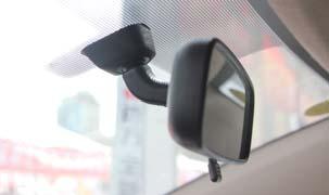
10 Replacement Monitor The mirror monitor replaces the existing car mirror. Carefully remove the mirror off the pin. Slide the replacement mirror on to the pin and secure it with the screw provided (already in the screw hole).different cars have different brackets, depending on your vehicle make and manufacturer. There are many methods to remove the original rearview mirror, however, please don t force the mirror off the bracket. The manufacturer will not be responsible for damage caused to your car by an improper mirror installation. BEFORE YOU BEGIN Camera & Cable Be sure to position the cable properly. The aviation camera cable uses aircraft grade connectors which means the camera cable can be exposed to all weather elements. Do not run the cable over sharp edges, do not kink the cable, and keep away from HOT and rotating parts. Fasten all cables and secure all excess cable. Connect camera to the camera extension cable running inside the vehicle. 10 Rear View Safety
11 Wiring After connecting the camera to the camera cable the camera should be plugged into AV2. Connect the RED 12V power wire to an ignition power source and the BLACK 12V ground wire to a chassis ground. The GREEN wire is the REVERSE trigger wire. Connect this wire to the vehicle s backup light circuit to activate the rear-view image whenever the vehicle shifts into reverse. To connect a second camera, connect it to AV1. It can be turned on by pressing the power button on the monitor. Precautions for use of Mirror Monitor I. The Mirror Monitor is made of glass. Do not subject it to a mechanical shock by dropping it from a high place, etc. II. Do not apply excessive force to the monitor surface or the adjoining areas since this may cause the color tone to vary. III. Only clean with a soft dry cloth and/or Windex. IV. Do not attempt to disassemble the mirror monitor. Safety Before drilling, be sure no cable or wire is on the other side. Feed as much cable as possible into vehicle & clamp securely. This reduces the possibility of cable being hooked or snagged. BEFORE YOU BEGIN Reverse With Confidence 11
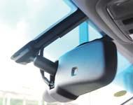
12 INSTALLATION GUIDE Installation and Wiring Different cars have different brackets/bases. It depends on your vehicle maker/manufacturer. There are many ways to remove the original rear view mirror. Do not force the mirror off the bracket. The manufacturer will not be responsible for any damage caused to your car by improper mirror installation. 12 Rear View Safety


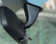


13 INSTALLATION GUIDE Bracket Type If the mirror monitor doesn t fit in your vehicle, please contact us. We have many different kinds of brackets and adaptors. Reverse With Confidence 13

14 By connec ng the green line, the reversing signal is input to the rear view mirror and reversing video can automa cally display on the wide 7.3 inch LCD monitor. How to Wire 3M Power harness 3M Power harness Audio Cables 5 Pin Camera Connector Green GreenRear signal Back car signal White Purple Trigger line 1 Trigger line 1 Orange Trigger line 2 Red to ACC +12V FUSE BOX Black to Red GNDto ACC +12V FUSE BOX 5 Pin Camera ConnectorBlack to GND 5 Pin Camera Connector Black to GND Red to ACC Black +12V to GND Red to ACC +12V Back up camera Back up video Black to GND Red to ACC +12V Left camera Black to GND Red to ACC +12V Le video The advisable installa on posi on WIRING for camera 7 Right video Le video Back up video 14 2V Rear View Safety


15 Adjustable Grid Lines Generally, to help drivers estimate the distance from obstacles, there are three lines for reference -red, yellow and green. These three lines are displayed on the monitor when car is reversing. The green line is 3m from the back of car and the yellow line is 2m. The distant red line is 1m from the back of car while the closed red line is 0.4m. Both reference lines on the left and right should leave 0.2m space from the car. 20CM 20CM The accuracy of the grid lines can vary based on how you angle your camera. Adjust the grid lines to compensate for inaccuracies. GRIDLINES Reverse With Confidence 15


16 Long press the Settings (middle) button on the remote to enter grid line adjustment mode. Press the Settings button again to toggle between left/right grid lines. Use the UP/DOWN/LEFT/RIGHT buttons to adjust grid line location, and the rotation buttons to adjust grid line angle. Right posi on Wrong posi on L R Display on the monitor GRIDLINES Press the bu on to choose L or R adjustable guide line Up Clockwise Le Right Down An -clockwise Remote control Move the guide line Rotate the guide line 16 Rear View Safety


17 Remote Control The remote must be used to change menu settings. Enter picture menu Menu parameter decrease Guide line up Menu parameter increase Guide line le Guide line right Enter guide line adjustment Guide line down Guide line clockwise Guide line an -clockwise Press to reset all menu and parameters How To Use Menu Short press MENU to enter PICTURE. Here you may choose BRIGHT- NESS, COLOR, CONTRAST, SCALE, START LOGO, or PRESET. Use the UP/DOWN buttons to change settings. REMOTE CONTROL Reverse With Confidence 17


18 Brightness Level Brightness/color/contrast levels range from 0 to 100. The default is 50. Color Level BASIC SETTINGS Contrast Level 18 Rear View Safety
19 Scale Adjustment Scale function will only work with gridlines. Choose ON/OFF. Default is ON. Start Logo On/Off Choose ON/OFF. Default is ON. Preset Menu Save basic settings. Choose ON/OFF. Default is OFF. Volume Adjustment Volume adjustments range from 0 to 100. The default is 80. BASIC SETTINGS Reverse With Confidence 19


20 MirrorLink Use mirrorlink to display your mobile phone on your rear view mirror monitor through WiFi and programs such as DLNA, Miracast and Airplay. Note: Bluetooth must be off to use mirrorlink. How to Connect (Android) MIRRORLINK Press the M button on your monitor, switch wireless mode to Android Device, and open the WiFi on phone. Search for mirror connection as shown on next page. M bu on 20 Rear View Safety


21 MIRRORLINK tap here tap here tap here After the mirror link is connected, press the CH button to toggle between single and dual display modes. A er nishing the connec on, then the phone screen projected onto the rear view mirror, you can press CH on TP bu on to choose double mobile dual mode or single-screen mode. Reverse With Confidence 21
22 How to Connect with iphone 1: Press the M button to switch the wireless mode to ios Device. M bu on 2: Search for the WiFi connection as shown below. Default password is After connecting, turn AirPlay on and turn on mirroring as shown below. 2: Using iphone search Wi-Fi (Wi-Fi name is displayed on the screen and shown as below), then enter the default password: A er nishing Wi-Fi connec on, bring up the shortcut menu, click on the AirPlay func on, select the device name, and open the mirroring. MIRROR LINK Wi-Fi name Tap here Turn on it Tap here 22 Rear View Safety


23 Channel Switching After the mirror link is connected, press the CH button to toggle between single 5.2 and Channel dual display switching modes. Press the CH bu on on the screen to switch display among CAMERA, VIDEO1, MOBILE, VIDEO1+MOBILE, MOBILE+VIDEO1, CAMERA+MOBILE, and MOBILE+CAMERA. Full Backup Camera Display Full CAMERA screen display DISPLAY MODES Reverse With Confidence 23


24 DISPLAY MODES Full Side Camera Display Full MirrorLink Display Full MOBILE screen display 24 Rear View Safety


25 Side Camera/MirrorLink Dual Display Backup Camera/MirrorLink Dual Display CAMERA and MOBILE display simultaneously DISPLAY MODES Reverse With Confidence 25
26 Please Note 1. This system has multiple display modes, including full side/rear camera displays, a full mirrorlink display, and multiple dual displays 2. When turned on, the screen will automatically show the last display mode viewed Triggering Video 1. Reversing your vehicle will trigger your rear camera. 2. The mirror will automatically switch to the full camera display when the brake or turn signals are used. TRIGGERING 3. When a camera/mirrorlink dual display is shown, gridlines will not be displayed. 26 Rear View Safety
27 ONE YEAR WARRANTY REAR VIEW SAFETY, INC. WARRANTS THIS PRODUCT AGAINST MATERIAL DEFECTS FOR A PERIOD OF ONE YEAR FROM DATE OF PURCHASE. WE RESERVE THE RIGHT TO REPAIR OR REPLACE ANY SUCH DEFECTIVE UNIT AT OUR SOLE DISCRETION. REAR VIEW SAFETY, INC. IS NOT RESPONSIBLE FOR A DEFECT IN THE SYSTEM AS A RESULT OF MISUSE, IMPROPER INSTALLATION, DAMAGE OR MISHANDLING OF THE ELECTRONIC COMPONENTS. REAR VIEW SAFETY, INC. IS NOT RESPONSIBLE FOR CONSEQUENTIAL DAMAGES OF ANY KIND. THIS WARRANTY IS VOID IF: DEFECTS IN MATERIALS OR WORKMANSHIP OR DAMAGES RESULT FROM REPAIRS OR ALTERATIONS WHICH HAVE BEEN MADE OR ATTEMPTED BY OTHERS OR THE UNAUTHORIZED USE OF NONCONFORMING PARTS; THE DAMAGE IS DUE TO NORMAL WEAR AND TEAR, THIS DAMAGE IS DUE TO ABUSE, IMPROPER MAINTENANCE, NEGLECT OR ACCIDENT; OR THE DAMAGE IS DUE TO USE OF THE REAR VIEW SAFETY, INC. SYSTEM AFTER PARTIAL FAILURE OR USE WITH IMPROPER ACCESSORIES. WARRANTY PERFORMANCE DURING THE ABOVE WARRANTY PERIOD, SHOULD YOUR REAR VIEW SAFETY PRODUCT EXHIBIT A DEFECT IN MATERIAL OR WORKMANSHIP, SUCH DEFECT WILL BE REPAIRED WHEN THE COMPLETE REAR VIEW SAFETY, INC. PRODUCT IS RETURNED, POSTAGE PREPAID AND INSURED, TO REAR VIEW SAFETY, INC. OTHER THAN THE POSTAGE AND INSURANCE REQUIREMENT, NO CHARGE WILL BE MADE FOR REPAIRS COVERED BY THIS WARRANTY. WARRANTY DISCLAIMERS NO WARRANTY, ORAL OR WRITTEN, EXPRESSED OR IMPLIED, OTHER THE ABOVE WARRANTY IS MADE WITH REGARD TO THIS REAR VIEW SAFETY, INC. REAR VIEW SAFETY, INC. DISCLAIMS ANY IMPLIED WARRANTY OR MERCHANT-ABILITY OR FITNESS FOR A PARTICULAR USE OR PURPOSE AND ALL OTHER WARRANTIES IN NO EVENT SHALL REAR VIEW SAFETY. INC. LIABLE FOR ANY INCIDENTAL, SPECIAL, CONSEQUENTIAL, OR PUNITIVE DAMAGES OR FOR ANY COSTS, ATTORNEY FEES, EXPENSES, LOSSES OR DELAYS ALLEGED TO BE AS A CONSEQUENCE OF ANY DAMAGE TO, FAILURE OF, OR DEFECT IN ANY PRODUCT INCLUDING, BUT NOT LIMITED TO, ANY CLAIMS FOR LOSS OF PROFITS. WARRANTY Reverse With Confidence 27
28 DISCLAIMER DISCLAIMER REAR VIEW SAFETY AND/OR ITS AFFILIATES DOES NOT GUARANTEE OR PROMISE THAT THE USER OF OUR SYSTEMS WILL NOT BE IN/PART OF AN ACCIDENT OR OTHERWISE NOT COLLIDE WITH AN OBJECT AND/OR PERSON. OUR SYSTEMS ARE NOT A SUBSTITUTE FOR CAREFUL AND CAUTIOUS DRIVING OR FOR THE CONSISTENT ADHERENCE TO ALL APPLICABLE TRAFFIC LAWS AND MOTOR VEHICLE SAFETY REGULATIONS. THE REAR VIEW SAFETY PRODUCTS ARE NOT A SUBSTITUTE FOR REARVIEW MIRRORS OR FOR ANY OTHER MOTOR VEHICLE EQUIPMENT MANDATED BY LAW. OUR CAMERA SYSTEMS HAVE A LIMITED FIELD OF VISION AND DO NOT PROVIDE A COMPREHENSIVE VIEW OF THE REAR OR SIDE AREA OF THE VEHICLE. ALWAYS MAKE SURE TO LOOK AROUND YOUR VEHICLE AND USE YOUR MIRRORS TO CONFIRM REARWARD CLEARANCE AND THAT YOUR VEHICLE CAN MANEUVER SAFELY. REAR VIEW SAFETY AND/OR ITS AFFILIATES SHALL HAVE NO RESPONSIBILITY OR LIABILITY FOR DAMAGE AND/OR INJURY RESULTING FROM ACCIDENTS OCCURRING WITH VEHICLES HAVING SOME OF REAR VIEW SAFETY PRODUCTS INSTALLED AND REAR VIEW SAFETY AND/ OR ITS AFFILIATES, THE MANUFACTURER, DISTRIBUTOR AND SELLER SHALL NOT BE LIABLE FOR ANY INJURY, LOSS OR DAMAGE, INCIDENTAL OR CONSEQUENTIAL, ARISING OUT OF THE USE OR INTENDED USE OF THE PRODUCT. IN NO EVENT SHALL REAR VIEW SAFETY AND/OR ITS AFFILIATES HAVE ANY LIABILITY FOR ANY LOSSES (WHETHER DIRECT OR INDIRECT, IN CONTRACT, TORT OR OTHERWISE) INCURRED IN CONNECTION WITH THE SYSTEMS, INCLUDING BUT NOT LIMITED TO DAMAGED PROPERTY, PERSONAL INJURY AND/OR LOSS OF LIFE. NEITHER SHALL REAR VIEW SAFETY AND/OR ITS AFFILIATES HAVE ANY RESPONSIBILITY FOR ANY DECISION, ACTION OR INACTION TAKEN BY ANY PERSON IN RELIANCE ON REAR VIEW SAFETY SYSTEMS, OR FOR ANY DELAYS, INACCURACIES AND/OR ERRORS IN CONNECTION WITH OUR SYSTEMS FUNCTIONS. 28 Rear View Safety
29 NOTES Notes Reverse With Confidence 29


30 If you have any questions about this product, contact: Rear View Safety, Inc Atlantic Avenue Brooklyn, NY IN NO EVENT SHALL SELLER OR MANUFACTURER BE LIABLE FOR ANY DIRECT OR CONSEQUENTIAL DAMAGES OF ANY NATURE, OR LOSSES OR EXPENSES RESULTING FROM ANY DEFECTIVE PRODUCT OR THE USE OF ANY PRODUCT. Better Cameras. Better Service. IT S OUR GUARANTEE. 30 Rear View Safety
Instruction Manual. Backup Camera System With Replacement Mirror Display RVS N
 Instruction Manual Backup Camera System With Replacement Mirror Display RVS-778718N Rear View Safety, Inc. 2016 1 NOTE! Please read all of the installation instructions carefully before installing the
Instruction Manual. OEM Frameless Rear View Replacement Mirror Monitor with 7.2" Dual Display RVS Reverse With Confidence 1
 Instruction Manual OEM Frameless Rear View Replacement Mirror Monitor with 7.2" Dual Display RVS-718-7 1 NOTE! Please read all of the installation instructions carefully before installing the product.
Please read all of the installation instructions carefully before installing the product. Improper installation will void manufacturer s warranty.
 TM 1 What s in the Box? Note: Configuration will vary depending what item options you select. ire 1 Color Sony CCD night vision weather proof backup camera 1 16 Camera Cable 1 Power Connection Wire Table
Instruction Manual. Backup Camera System With Replacement Mirror Monitor RVS
 Instruction Manual Backup Camera System With Replacement Mirror Monitor RVS-770718 Reverse With Confidence, Inc. 2016 1 TABLE OF CONTENTS Introduction............................... 03 Safety Information..........................
Introduction RVS SYSTEMS
 What s in the Box? 1 Split Screen Digital Wireless Monitor with Cigarette Lighter Adaptor 1 CCD Wireless Backup Camera with Power Cable 1 Extendable Suction Cup Mount for Monitor Table of Contents Introduction...4
Instruction Manual. Backup Camera System For Pickup Trucks. RVS-Pickup
 Instruction Manual Backup Camera System For Pickup Trucks RVS-Pickup Rear View Safety, Inc. 2016 1 NOTE! Please read all of the installation instructions carefully before installing the product. Improper
Instruction Manual. Backup Sensor Reversing System RVS-RS103
 Instruction Manual Backup Sensor Reversing System RVS-RS103 RVS Systems, Inc. 2017 TABLE OF CONTENTS System Description............................ 03 Safety Information........................... 04 Before
What s in the Box? REAR VIEW SAFETY
 What s in the Box? 1 x 7" LED Digital Color Monitor 1 x Flush Mount Backup Camera 1 x 66' Camera Cable 1 x Universal Swivel Head Mount 1 x Remote Control 1 x RCA Adaptor 1 x Hole Saw 1 x Screw Kit For
A Safe Fleet Brand. Instruction Manual. G-SERIES Backup Camera System with Navigation and Bluetooth RVS NAVBT
 A Safe Fleet Brand Instruction Manual G-SERIES Backup Camera System with Navigation and Bluetooth RVS-776718-NAVBT Reverse With Confidence, Inc. 2017 1 TABLE OF CONTENTS Introduction...............................
AOM-78 7 MONOCHROME OBSERVATION 90 DAY/12 MONTH LIMITED WARRANTY
 BACK COVER FRONT COVER UDIOVOX The Mobile Electronics Company PECIALIZED PPLICATIONS, L.L.C. 90 DAY/12 MONTH LIMITED WARRANTY AUDIOVOX SPECIALIZED APPLICATION, LLC (the company) warrants to the original
AUTO-BLiP. User Manual Porsche INTELLIGENT DOWNSHIFTS. Version 1.2
 AUTO-BLiP INTELLIGENT DOWNSHIFTS www.auto-blip.com User Manual 2005+ Porsche Version 1.2 Copyright 2012 Tractive Technology, LLC. All rights reserved. Page 1 WARNING Use of the AUTO-BLiP while driving
AUTO-BLiP. User Manual Lotus INTELLIGENT DOWNSHIFTS. Version 1.0
 AUTO-BLiP INTELLIGENT DOWNSHIFTS www.auto-blip.com User Manual Lotus Version 1.0 Copyright 2012 Tractive Technology, LLC. All rights reserved. Page 1 WARNING Use of the AUTO-BLiP while driving could lead
Rearview Mirror with 4" Color LCD Monitor and Camera Package Model: RVMPKG4 (V2.0) User s Manual
 User s Manual") Rearview Mirror with 4" Color LCD Monitor and Camera Package Model: RVMPKG4 (V2.0) User s Manual Features: Rearview Mirror with 4" LCD Monitor Built-In Speaker Rearview Camera Input Auxiliary Video Input
Rearview Mirror with 4" Color LCD Monitor and Camera Package Model: RVMPKG4 (V2.0) User s Manual Features: Rearview Mirror with 4" LCD Monitor Built-In Speaker Rearview Camera Input Auxiliary Video Input
AUTO-BLiP. User Manual Ford Mustang INTELLIGENT DOWNSHIFTS. Version 1.2
 AUTO-BLiP INTELLIGENT DOWNSHIFTS www.auto-blip.com User Manual 2015-2016 Ford Mustang Version 1.2 Copyright 2012 Tractive Technology, LLC. All rights reserved. Page 1 WARNING Use of the AUTO-BLiP while
AUTO-BLiP. User Manual Chevrolet Corvette. Version 1.2
 AUTO-BLiP INTELLIGENT DOWNSHIFTS www.auto-blip.com User Manual 1997-2004 Chevrolet Corvette Version 1.2 Copyright 2012 Tractive Technology, LLC. All rights reserved. Page 1 WARNING Use of the AUTO-BLiP
AUTO-BLiP. User Manual Chevrolet Corvette. Version 1.7
 AUTO-BLiP INTELLIGENT DOWNSHIFTS www.auto-blip.com User Manual 2008-2013 Chevrolet Corvette Version 1.7 Copyright 2012 Tractive Technology, LLC. All rights reserved. Page 1 WARNING Use of the AUTO-BLiP
Vehicle Rear Observation System With Integrated Parking Sensors
 Vehicle Rear Observation System With Integrated Parking Sensors Model: CAMSBAR Installation/User Manual Features: 2.5" LCD Color Display 2 Ultra Sonic Rear Obstacle Sensors On-screen Display Function Automatically
Installation Instructions for the Lingenfelter Fan and Pump Manual Override Kit
 Installation Instructions for the Lingenfelter Fan and Pump Manual Override Kit PN: L300180000 v1.1 Lingenfelter Performance Engineering 1557 Winchester Road Decatur, IN 46733 (260) 724-2552 (260) 724-8761
BP1204 INSTALLATION/OWNER'S MANUAL
 BP1204 INSTALLATION/OWNER'S MANUAL BP1204 PREPARATION Getting Started Thank you for purchasing the Dual Electronics BP1204 Bandpass Subwoofer System. Although Dual has attempted to ensure the information
INVERTER HARNESS INSTALLATION FOR FREIGHTLINER CASCADIA
 FOR FREIGHTLINER CASCADIA Part #: P808 1004FC 08/05/2014 Doc 1.04 INST065 Page 1 Step 1: Unpack the plate assembly and both positive and negative cables. INSTALLATION INSTRUCTIONS Step 2: Insert the negative
DYNOTUNE 2 STAGE RPM WINDOW SWITCH WITH TPS INSTALLATION INSTRUCTIONS
 DYNOTUNE 2 STAGE RPM WINDOW SWITCH WITH TPS INSTALLATION INSTRUCTIONS Introduction: READ ALL INSTRUCTIONS BEFORE STARTING! This DynoTune device will control up to two stages of nitrous oxide. They are
Transmission Guardian
 Transmission Guardian Thank you for purchasing the Transmission Guardian from Bowler Performance Transmissions. We hope you are 100 percent satisfied with your purchase and if for any reason you are not,
HBC-20 - LED HIGH BAY
 To prevent death, injury or damage to property, this product must be installed in accordance to National Electrical Code (NFPA70) in the US or Canadian Electrical Code (CSA.) in Canada. Risk of fire or
DIRECT PLUS/FLEX/MAX INSTALLATION GUIDE. INST165 Doc 1.04
 DIRECT PLUS/FLEX/MAX INSTALLATION GUIDE INST165 Doc 1.04 CONTENTS General Information...2 Diagrams...3 Mounting the Direct Nosebox...5 Main Harness Installation...6 Interior Light Harness Installation...10
DUAL WIDEBAND AIR/FUEL RATIO GAUGE Product Numbers: GS-W702W_Dual, GS-C702W_Dual, GS-T702W_Dual
 Installation Instructions Tech Support: 856.768.8300 TechSupport@GlowShiftGauges.com DUAL WIDEBAND AIR/FUEL RATIO GAUGE Product Numbers: GS-W702W_Dual, GS-C702W_Dual, GS-T702W_Dual (1) Gauge (2) Controllers
60 PSI Boost Gauge. For Product Numbers: MT-DV01_60, MT-WDV01_60
 60 PSI Boost Gauge For Product Numbers: MT-DV01_60, MT-WDV01_60 Red: 12v Constant (un-switched) Source (+) Orange: 12v Dimmer (switched) Source (+) (optional) White: 12v Ignition (switched) Source (+)
37SCENE 46SCENE 79SCENE
 Installation and Operation Instructions LED SCENE LIGHT LED SCENE LIGHT 37SCENE 46SCENE 79SCENE 37SCENE 46SCENE Introduction The 37SCENE, 46SCENE, 79SCENE LED Scene Lights are designed for the emergency
INSTALLATION INSTRUCTIONS THERMOCOUPLE EXPANSION MODULE
 INSTALLATION INSTRUCTIONS THERMOCOUPLE EXPANSION MODULE 2650-1846-77 Rev. B Details: Temperature Rating: -40 C to 85 C/-40 F to 185 F Vibration Specification: 20 g continuous, 50 g shock Inputs: o 4 EGT
INSTALLATION/OWNERS MANUAL
 INSTALLATION/OWNERS MANUAL XOBP12D PREPARATION Getting Started Thank you for purchasing the Dual Electronics XOBP12D Bandpass Subwoofer System. Although Dual has attempted to make sure all of the information
PVI 1800/PVI Residential/Commercial Grid-Tied Photovoltaic Inverter WARRANTY MANUAL. Subject to Change REV , Solectria Renewables
 PVI 1800/PVI 2500 WARRANTY MANUAL Residential/Commercial Grid-Tied Photovoltaic Inverter 2009, Solectria Renewables Subject to Change REV 10.09 1 Product Warranty & RMA Policy 1.1 Warranty Policy The Solectria
Do not install and/or operate this safety product unless you have read and understand the safety information contained
 Installation and Operation Instructions ED3766 TRI Color Directional LED Available in various color combinations, the ED3766 Directional LED is a surface mount, tri-color warning light that is ideal for
User Guide IGD Series
 US User Guide IGD Series DANGER PRIOR TO USE, READ AND UNDERSTAND PRODUCT SAFETY INFORMATION. Failure to follow the instructions may result in ELECTRICAL SHOCK, EXPLOSION, or FIRE, which may result in
SELECT -24 INSTALLATION GUIDE. INST036 Doc 2.02
 SELECT -24 INSTALLATION GUIDE INST036 Doc 2.02 CONTENTS General Information...2 Select-24 Diagram...3 Mounting the Select Controller...4 Dual Pole Nosebox Installation...5 Aux Harness Installation...6
EAGL 1-Touch Laser Level
 EAGL 1-Touch Laser Level Owner s Manual GENERAL INFORMATION Thank you for buying the EAGL 1-Touch laser. Although it is very simple to use, we recommend that you read this manual before operating the laser.
Wiring Installation Instructions for : Pressure. Wiring Installation Instructions for : Temperature. 2 1/16 Spek Pro Professional Racing Gauge
 Wiring Installation Instructions for : Pressure DIAGRAM 1 Pressure Sensor 1/8 NPT 3 AMP Wiring Installation Instructions for : Temperature GAUGE 12-Pin Wiring Harness & Plug Firewall Grommet DIAGRAM 2
Installation & Operators Manual
 Installation & Operators Manual Model Serial Number Purchase Date 2007-2008 SegVator, LLC Patent Pending All Rights Reserved Important Safety Information Make sure the vehicle has a properly installed
STC2 Car Kit. Installation Guide
 STC2 Car Kit Installation Guide Box Contents When you unpack your STC2 Car Kit, it should include everything as shown below: Suction Cup Mount & Screws Surface Preparation Cleaning Kit (To clean a surface
SOLAR DASH CHARGING SYSTEM USER GUIDE
 SOLAR DASH CHARGING SYSTEM Doc 1.01 INST049 INSTALLATION STEP 1 Place 20 watt solar panel in the dash of the vehicle facing up. Note: For ideal results position the vehicle in a manner in which the solar
INSTALLATION, MAINTENANCE & SERVICE MANUAL
 INSTALLATI, MAINTENANCE & SERVICE MANUAL M151217L Product Specifications 20" (506mm) 3.3 (85mm) 9.8 (250mm) 38" (974mm) 4.2 (106mm) 9.8 (250mm) 48" (1208mm) 4.2 (106mm) 56" (1442mm) 4.2 (106mm) Wiring
Do not install and/or operate this safety product unless you have read and understand the safety information contained in this manual.
 Installation and Operation Instructions MR Tri- Light Available in various color combinations, the MR Directional LED surface mount, tri-color warning light is ideal for a wide variety of auxiliary warning
SOLAR BOLT CHARGING SYSTEM INSTALLATION GUIDE
 CHARGING SYSTEM Doc 1.00 INST052 1 SOLAR BOLT CHARGING SYSTEM CONTENTS General Information... 2 Solar Panel Installation... 3 Solar Bolt Main Harness and Indicate Installation... 4 Cable Routing... 9 Solar
WiFi Tank Level Monitor Installation Instructions
 WiFi Tank Level Monitor Installation Instructions COMPATIBILITY To install the Tank Utility remote level monitor, you will need the following: A WiFi connection at your tank site An Apple or Android smartphone
AOM452 In-Car LCD Display System Package Installation Manual
 AOM452 In-Car LCD Display System Package Installation Manual Features: 4.5 TFT Color LCD Display Camera 1 input for Rearview camera Camera 2 input for Side view camera Navigation Input Cautions! The product
A/C PRESSURE MONITOR INSTALLATION INSTRUCTIONS SYSTEM OPERATION GREEN INDICATOR LIGHT
 A/C PRESSURE MONITOR INSTALLATION INSTRUCTIONS Do not attempt to clean or inspect anything while the engine is running. Cleaning and inspection must be done by a certified mechanic. All A/C service must
ELECTRICALLY INSULATED 14mm PROBE
 99 Washington Street Melrose, MA 02176 Phone 781-665-1400 Toll Free 1-800-517-8431 Visit us at www.testequipmentdepot.com ELECTRICALLY INSULATED 14mm PROBE USER S MANUAL NOTE: ETL SAFETY RATING ONLY APPLIES
TALCO FIRE SYSTEMS. LSF Start-Up Instructions. 1) IMPORTANT: Inspect the unit for damage. Report any damage to the freight carrier immediately.
 IMPORTANT: Inspect the unit for damage. Report any damage to the freight carrier immediately.") LSF Start-Up Instructions 1) IMPORTANT: Inspect the unit for damage. Report any damage to the freight carrier immediately. 2) PRE-START-UP: Be sure there is water in the pump. Bleed air at all high points
LSF Start-Up Instructions 1) IMPORTANT: Inspect the unit for damage. Report any damage to the freight carrier immediately. 2) PRE-START-UP: Be sure there is water in the pump. Bleed air at all high points
Premium OEM Style 4.3 Replacement Mirror Monitor
 Premium OEM Style 4.3 Replacement Mirror Monitor RVM-043A User Manual Thank you for purchasing Parkmate s RVM-043A Premium OEM Style 4.3 Replacement Rear View Mirror Monitor. This state of the art Parkmate
END USER TERMS OF USE
 END USER TERMS OF USE The following is the End Users Terms of Use as it currently appears in the Mobileye User Manual and Warranty information. This is here for your review and information; it is subject
DIGIGAUGE P R E S S U R E D I S P L A Y S Y S T E M I N S T R U C T I O N M A N U A L
 DIGIGAUGE P R E S S U R E D I S P L A Y S Y S T E M I N S T R U C T I O N M A N U A L Thank you for purchasing DigiGauge by ZAETECH Disclaimer DigiGauge is for show and off road use only. By using this
SELECT/DIRECT DEMO BOX USER GUIDE. INST164 Doc 1.00
 SELECT/DIRECT DEMO BOX USER GUIDE INST164 Doc 1.00 CONTENTS Using the Demo Box...2 Direct Dual Pole (Stinger) Demonstration...5 Select Dual Pole, Reefer, or Aux Demonstration...6 Switch Board Callouts...7
Thermaltake Warranty / Support Information
 Thermaltake Warranty / Support Information Technical Support Thermaltake is committed to providing the highest quality, most reliable products for our valued customer. There are several ways you may contact
USER GUIDE EMERGENCY JUMP STARTER PORTABLE POWER SUPPLY INTELLIBOOST ULTRA RG600 12V 600A REV 1.16B
 WWW.RUGGEDGEEK.COM USER GUIDE EMERGENCY JUMP STARTER PORTABLE POWER SUPPLY INTELLIBOOST ULTRA RG600 12V 600A REV 1.16B IMPORTANT THE RG600 IS AN EMERGENCY TOOL AND SHOULD BE KEPT FULLY CHARGED, IN CASE
Aftermarket Helio Installation Guide. Version 1.0.2
 Aftermarket Helio Installation Guide Version 1.0.2 Date: 9/30/2015 ID: aftermarket-helio-install Number of Pages: 9 File Name: 150930_aftermarket-helio-install_V1.0.2 Revision History Configuration Item
ROTARY HEAD DIGITAL STEM THERMOMETER
 ROTARY HEAD DIGITAL STEM THERMOMETER 99 Washington Street Melrose, MA 02176 Phone 781-665-1400 Toll Free 1-800-517-8431 Visit us at www.testequipmentdepot.com DT340RH Please read this manual carefully
PVI 60KW, PVI 82KW, PVI 95KW
 PVI 60KW PVI 82KW PVI 95KW WARRANTY MANUAL Commercial, Grid-Tied Photovoltaic Inverters 2008, Solectria Renewables LLC Subject to Change DOC-020099 rev 024 1 1 Product Warranty & RMA Policy Warranty Policy
SUNTURA SOLAR TRACKER
 WindyNation SUNTURA SOLAR TRACKER SOT-TRKS-NF User s Manual Page 1 of 10 WindyNation 08/09/2012 Table of Contents 1 Introduction... 3 1.1 Limited Warranty... 3 1.2 Restrictions... 3 1.3 Warranty Claims
Rear Observation System Package Model RVMPKG1 Installation Manual
 Rear Observation System Package Model RVMPKG1 Installation Manual Features: Rearview Mirror with 4 LCD 2 Built in Speakers Rearview Camera Input Auxiliary Video Input Video System Auto Detection for PAL/NTSC
DUAL PURPOSE DIAGNOSTIC LEAK DETECTOR
 OPERATION MANUAL DUAL PURPOSE DIAGNOSTIC LEAK DETECTOR P/N 95-030 NIS -800-662-200 nissantechmate.com CONTENTS Specifications / Warranty... Functions...2-3 Accessories... 4 Set-Up... 5 Adaptor Installation...
Owner s Installation Guide
 Owner s Installation Guide Introduction The nophoto is a highly advanced smart detterent device designed to protect your license plate from flash photography. Using patented technology, the nophoto reacts
Users Guide for Ac-sync
 Problem solved. Users Guide for Ac-sync Thank you for choosing Anywhere Cart! The AC-SYNC is designed to sync, charge and store 1-36 ipads or tablets. Adjustable device divider bays allow fitment of any
BATHROOM ACCESSORIES
 BATHROOM ACCESSORIES ORCA HARDWARE WARRANTY Orca Hardware warrants its products manufactured to be free from defects in materials and workmanship for a period of ten (10) years from the date of purchase,
INSTRUCTION MANUAL WARNING
 INSTRUCTION MANUAL WARNING Please make sure you read the entire instruction manual to become familiar with the features of your aircraft before operating. Failure to operate this product correctly can
PIAA Multi-Fit 005/1100X Light Bracket Kits
 ENGLISH PIAA Multi-Fit 005/1100X Light Bracket Kits Thank you for your purchase. Please read all the instructions before beginning.! WARNING Lighting laws vary state to state, check your local laws before
DWS404 DWS524 DWS654 DWS684 DWS694. DWS SERIES INSTALLATION/OWNER'S MANUAL Car Audio Speakers
 DWS404 DWS524 DWS654 DWS684 DWS694 DWS SERIES INSTALLATION/OWNER'S MANUAL Car Audio Speakers PREPARATION Safety Guidelines Thank you for purchasing the DWS Series car speakers. Although Dual has attempted
Installation Instructions
 Safe Operation Practices Set-Up Operation Maintenance Service Troubleshooting Warranty Installation Instructions RZT & Z-Force Light Kit Model 19B70032100 WARNING READ AND FOLLOW ALL SAFETY RULES AND INSTRUCTIONS
PACKAGE LIST CONTENT. User Manual 1 GIMBAL STABILIZER 1 MICRO USB CABLE 1
 CONTENT Package List...1 Disclaimer and Warning...2 Safety Operation Guidelines...4 USB Connection...7 Mounting Camera, Checking Balance...9 Panel Introduction...10 Operating Mode...11 Changing Orientation...12
MaxLite LED Linear HighBay Fixtures
 Operating Instructions MaxLite LED Linear HighBay Fixtures General Safety Information To reduce the risk of death, personal injury or property damage from fire, electric shock, falling parts, cuts/abrasions,
WARRANTY POLICY. Grid-Tied Photovoltaic Inverters. Revision D. 2014, Solectria Renewables, LLC DOCIN
 WARRANTY POLICY Revision D 2014, Solectria Renewables, LLC DOCIN-070360 1 Product Warranty & RMA Policy 1. Warranty Policy Warranty Registration: It is important to have updated information about the inverter
Installation and Operation Instructions Safety Director Arrow
 Installation and Operation Instructions Safety Director Arrow! WARNING! Failure to install or use this product according to manufacturers recommendations may result in property damage, serious bodily/personal
SHOTLOCK OWNER S MANUAL TABLE OF CONTENTS -3-
 SHOTLOCK OWNER S MANUAL Thank you for purchasing a ShotLock Solo Vault. Now, you can enjoy peace-of-mind knowing your personal defense shotgun is always close, secure and ready. When the first-responder
SUNTURA HD SOLAR TRACKER
 WindyNation SUNTURA HD SOLAR TRACKER SOT-TRKS-NFHD User s Manual Page 1 of 11 WindyNation 08/09/2012 Table of Contents 1! Introduction... 3! 1.1! Limited Warranty... 3! 1.2! Restrictions... 3! 1.3! Warranty
Owner s Guide. Dumbwaiter. Series DUMBWAITER OWNER S GUIDE 1
 Owner s Guide Dumbwaiter Series 007 011 DUMBWAITER OWNER S GUIDE 1 DUMBWAITER OWNER S GUIDE 2 Congratulations on your choice of a Waupaca Elevator, Company, Inc., Dumbwaiter (W.E.C.). Your dumbwaiter is
INSTALLATION/OWNER'S MANUAL DP " Woofer in Enclosure
 INSTALLATION/OWNER'S MANUAL DP1000 10" Woofer in Enclosure Installation Thank you for purchasing the DP1000 10" Woofer with enclosure. Although Dual has attempted to make sure all of the information contained
ActuLink ABS Module - ABS-MOD-400
 Installation Instructions ActuLink ABS Module - ABS-MOD-400 For more information on the installation and operation of Tuson s towable ABS system, consult the installation and operations manuals for the
110 Volt/12 Volt Portable Inflator
 110 Volt/12 Volt Portable Inflator Owner s Manual WARNING: Read carefully and understand all ASSEMBLY AND OPERATION INSTRUCTIONS before operating. Failure to follow the safety rules and other basic safety
10 Ch Peak & Hold Injector Driver PN
 Installation Instructions 10 Ch Peak & Hold Injector Driver PN 30-2710 WARNING: installation is not for the electrically challenged! Use this product with extreme caution! If you are uncomfortable with
Woolich Racing. Bike Harness Installation Instructions Suzuki Harness Type 4a GSX1300R (Hayabusa)
") Woolich Racing Bike Harness Installation Instructions Suzuki Harness Type 4a 2013+ GSX1300R (Hayabusa) 1) Introduction To connect your Woolich Racing product to the ECU ( Engine Control Unit or computer)
Woolich Racing Bike Harness Installation Instructions Suzuki Harness Type 4a 2013+ GSX1300R (Hayabusa) 1) Introduction To connect your Woolich Racing product to the ECU ( Engine Control Unit or computer)
DUAL LINEAR MOTOR / ACTUATOR CONTROLLER W/ CURRENT SENSING AUTO REVERSE
 PAC-3200 DUAL LINEAR MOTOR / ACTUATOR CONTROLLER W/ CURRENT SENSING AUTO REVERSE PAC-3200 PRESET BUTTONS MOTOR 2 DUAL LINEAR MOTOR CONTROLLER WITH SAFETY REVERSE MOTOR 2 MOTOR 1 MAIN #1 ACC DISABLE #2
NORMAL/DIAL BRIGHTNESS: Press the down or up button to adjust dial brightness. Press the center button to save and advance to PEAK PLAYBACK.
 Flow Chart Programming Instructions for : VOLTMETER 2 1/16 Program Main Menu (Press one button at a time) START HERE Main Menu ONE NORMAL/DIAL BRIGHTNESS: Press the down or up button to adjust dial brightness.
CRD610 Automatic Fitting Inserter
 CRD610 Automatic Fitting Inserter OPERATIONS MANUAL VERSION 1.2 LAST EDITED 12.12.2018 cleanroomdevices.com 1 Table of Contents Title Page. 1 Table of Contents...2 1.0 General Product & Safety Information....3
TBX10A INSTALLATION/OWNER'S MANUAL 10" Sealed Enclosure with Built-in Amplifier
 TBX10A INSTALLATION/OWNER'S MANUAL 10" Sealed Enclosure with Built-in Amplifier Getting Started Thank you for purchasing the Dual TBX10A 10" ported enclosure with built-in amplifier. Although Dual has
RV-10 Center Arm Rest Console
 RV-10 Center Arm Rest Console Important Notice: This manual contains important information that may affect the safety of your aircraft. Read the Warranty / Agreement below. There is information in the
Read all instructions before installing and using. Installer: This manual must be delivered to the end user.
 Installation Instructions Vacuum / Magnet Mount Kits IMPORTANT! Read all instructions before installing and using. Installer: This manual must be delivered to the end user.! WARNING! Failure to install
DAP-625S and DAP-875S
 AIR CHAMP PRODUCTS DAP-625S and DAP-875S (i) FORM NO. L-20078-B-0501 In accordance with Nexen s established policy of constant product improvement, the specifications contained in this manual are subject
Installation and Operation Guide
 Bus-Scan CR2 RF Installation and Operation Guide All Content and Information are Copyright 2018 Robotics Technologies, Inc. Features and Information are subject to change without notice. All Rights Reserved.
MEX (55) QRO (442) Web Controls
 QRO (442) Web Controls") Web Controls SINGLE AND DUAL ROTOR TENSION CONTROL BRAKES MODELS:,,,, AND INSTALLATION, OPERATION, AND MAINTENANCE INSTRUCTIONS Read this manual carefully, making full use of its explanations and instructions.
Web Controls SINGLE AND DUAL ROTOR TENSION CONTROL BRAKES MODELS:,,,, AND INSTALLATION, OPERATION, AND MAINTENANCE INSTRUCTIONS Read this manual carefully, making full use of its explanations and instructions.
Straight-Bore Clutch LSCC-32, 44, 54
 Straight-Bore Clutch LSCC-32, 44, 54 1 In accordance with Nexen s established policy of constant product improvement, the specifications contained in this manual are subject to change without notice. Technical
Woolich Racing. Bike Harness Installation Instructions Hayabusa Gen 2 (08+)
") Woolich Racing Bike Harness Installation Instructions Hayabusa Gen 2 (08+) 1) Introduction To connect your Woolich Racing product to the ECU ( Engine Control Unit or computer) in your bike you need to
Woolich Racing Bike Harness Installation Instructions Hayabusa Gen 2 (08+) 1) Introduction To connect your Woolich Racing product to the ECU ( Engine Control Unit or computer) in your bike you need to
BIM-17-2 Bus Interface Module for compass and outside temperature
 BIM-17-2 Bus Interface Module for compass and outside temperature Mount the temperature sensor in the front grill area or another location that can get good air flow while the vehicle is being driven.
ENTR. Smart Door Lock. Quick Start Guide. The full user manual can be found online at: anges.indd 1 16-Aug-17 18:14:5
 ENTR Smart Door Lock Quick Start Guide The full user manual can be found online at: https://entrlock.com/support/ anges.indd 6-Aug-7 8::5 (0) Getting Started!Warning! V output NOT STANDARD USB - 5 h Warning:
CU6703 Module Installation Guide
 Up to 30% More Horsepower 10-20% Fuel Savings Cummins 6.7L Tier III Engines CU6703 Module Installation Guide AgDieselSolutions.com MAP sensor male and female connectors. Power and Ground wires. Module
Installation and Operation Guide
 Bus-Scan 500 RF Installation and Operation Guide All Content and Information are Copyright 2018-2019 Robotics Technologies, Inc. Features and Information are subject to change without notice. All Rights
6-TON DOUBLE LOCKING JACK STANDS OWNER S MANUAL
 6-TON DOUBLE LOCKING JACK STANDS OWNER S MANUAL WARNING: Read carefully and understand all ASSEMBLY AND OPERATION INSTRUCTIONS before operating. Failure to follow the safety rules and other basic safety
DODGE CUMMINS 24V ISB OEM BYPASS LIFT PUMP KIT Installation Instructions Part #
 2/15/2006 2000-2002 Dodge Cummins OEM Bypass Lift Pump Kit # 1050229-1 - 2000-02 DODGE CUMMINS 24V ISB OEM BYPASS LIFT PUMP KIT Installation Instructions Part # 1050229 PLEASE READ ALL INSTRUCTIONS CAREFULLY
PAC-3100 LINEAR MOTOR CONTROLLER W/ CURRENT SENSING AUTO REVERSE
 PAC-3100 LINEAR MOTOR CONTROLLER W/ CURRENT SENSING AUTO REVERSE Switch 1 (safety disable, page 3 for more detail) ON - Disables preset buttons and external presets when key is ON OFF - Buttons work the
Heliporter. Owner s Manual. 150 Series. by Paravion Technology, Inc.
 Heliporter by Paravion Technology, Inc. Owner s Manual 150 Series Introduction Congratulations, you have purchased one of the finest helicopter ground handling vehicles on the market today. We at Paravion
WARNING. Laser light is extremely bright and can potentially cause permanent eye damage or interfere with critical operations if improperly used.
 TG7630G / TG7630R TRUGLO, Inc. 525 International Parkway RICHARDSON, TEXAS 75081 MADE IN CHINA Green Laser: POWER OUTPUT
App View and Solar-Powered Parking Sensor
 App View and Solar-Powered Parking Sensor WP ITM. BT56485 / BT56485F Care & Use Instructions Important, retain for future reference: Read carefully TABLE OF CONTENTS 1. Introduction...1 2. Package Contents...2
Single-Position Detent Clutch DC Series. (i) MTY (81) MEX (55) QRO (442)
 MTY (81) MEX (55) QRO (442)") Single-Position Detent Clutch DC Series (i) FORM NO. L-2017-A-001 In accordance with Nexen s established policy of constant product improvement, the specifications contained in this manual are subject
Single-Position Detent Clutch DC Series (i) FORM NO. L-2017-A-001 In accordance with Nexen s established policy of constant product improvement, the specifications contained in this manual are subject
Nature Power Inverters. True Sinewave Inverter Modified Sinewave Inverter. Owner s Manual
 Version 1.1 Version 2 Nature Power Inverters True Sinewave Inverter Modified Sinewave Inverter Owner s Manual!!!!!!!!!!! 38304 38204 For safe and optimum performance, the Power Inverter must be used properly.