A Safe Fleet Brand. Instruction Manual. G-SERIES Backup Camera System with Navigation and Bluetooth RVS NAVBT
|
|
|
- Ann Griffith
- 6 years ago
- Views:
Transcription


1 A Safe Fleet Brand Instruction Manual G-SERIES Backup Camera System with Navigation and Bluetooth RVS NAVBT Reverse With Confidence, Inc

2 TABLE OF CONTENTS Introduction Safety Information Before Beginning Installation Installation Guide Adjustable Grid Line Installation and Wire GPS Navigation Menu and Function Bluetooth Setting and Instruction Monitor Specifications Camera Specification Camera Installation Troubleshooting Warranty & Disclaimer
3 NOTE! Please read all of the installation instructions carefully before installing the product. Improper installation will void manufacturer s warranty. Congratulations on purchasing a Rear View Backup Camera System! With this manual you will be able to properly install and operate the unit. The Backup Camera System is intended to be installed as a supplement aid to your standard rear view mirror that already exists in your vehicle. The Backup Camera System should not be used as a substitute for the standard rear view mirror or for any other mirror that exists in your vehicle. In some jurisdictions, it is unlawful for a person to drive a motor vehicle equipped with a TV viewer or screen located forward of the back of the driver s seat or in any location that is visible, directly or indirectly, to the driver while operating the vehicle. INTRODUCTION Reverse With Confidence 3
4 Please read the entire manual and follow the instructions and warnings carefully. Failure to do so can cause serious damage and/or injury, including loss of life. Be sure to obey all applicable local traffic and motor vehicle regulations as it pertains to this product. Improper installation will void manufacturer s warranty. SAFETY INFORMATION The Rear View Camera System is designed to help the driver safely detect people and/or objects helping to avoid damage or injury. However, you the driver, must use it properly. Use of this system is not a substitute for safe, proper or legal driving. Never back up while looking at the monitor alone. You should always check behind and around the vehicle when backing up, in the same way as you would if the vehicle did not have the Rear View Camera System. If you back up while looking only at the monitor, you may cause USAGE: damage or injury. Always back up slowly. The Rear View Camera System is not intended for use during extensive back-up maneuvers or backing into cross traffic or pedestrian walkways. Please, always remember, the area displayed by the Rear View Camera System is limited. It does not display the entire panorama that is behind you. 4
5 INSTALLATION: Electric shock or product malfunction may occur if this product is installed incorrectly. Use this product within the voltage range specified. Failure to do so can cause electronic shock or product malfunction. Take special care when cleaning the monitor. Make sure to firmly affix the product before use. If smoke or a burning smell is detected, disconnect the system immediately. Where the power cable may touch a metal case, cover the cable with friction tape. A short circuit or disconnected wire may cause a fire. While installing the Rear View System be careful with the wire positioning in order to avoid wire damage. The Rear View System should only be used when the vehicle is in reverse. Do not watch movies or operate the monitor while driving; as it may cause an accident. Do not install the monitor where it may obstruct drivers view or obstruct an air bag device. Dropping the unit may cause possible mechanical failure. SAFETY INFORMATION Reverse With Confidence 5
6 If you have questions about this product, contact: 1797 Atlantic Avenue Brooklyn, NY Tel: SAFETY INFORMATION IN NO EVENT SHALL SELLER OR MANUFACTURER BE LIABLE FOR ANY DIRECT OR CONSEQUENTIAL DAMAGES OF ANY NATURE, OR LOSSES OR EXPENSES RESULTING FROM ANY DEFECTIVE PRODUCT OR THE USE OF ANY PRODUCT. A Safe Fleet Brand 6
7 Before drilling please check that no cable or wiring is on the other side of the wall. Please clamp all wires securely to reduce the possibility of them being damaged while vehicle is in use. Keep all cables away from hot or moving parts and electrical noisy components. We recommend doing a benchmark test before installation to insure that all components are working properly. Step 1: Choose the monitor and camera locations. Step 2: Install all cables in vehicle, when necessary a 0.8 (20mm) hole should be drilled for passing camera cable through vehicles walls. Install split grommets where applicable. Step 3: Once all cables and wiring have been properly routed, perform a system function test by temporarily connecting the system. If the system seems to not be operating properly see troubleshooting (page 35). BEFORE YOU BEGIN Reverse With Confidence 7
8 Replacement Monitor The mirror monitor replaces the existing car mirror. Carefully remove the mirror off the pin. Slide the replacement mirror on to the pin and secure it with the screw provided (already in the screw hole).different cars have different brackets. Depending on your vehicle make and manufacturer. There are many methods to remove the original rearview mirror, however, please don t force the mirror off the bracket. The manufacturer will not be responsible for damage caused to your car by wrong installation of the mirror. Figure 1.1 INSTALLATION GUIDE Clip-On Monitor 1. The Mirror Monitor attaches to the existing rear view mirror in vehicle with the pressurized clips on the back of the monitor. 2. Attach monitor to existing mirror, and adjust mounting angle to allow optimum driver viewing comfort. Camera & Cable Be sure to position the cable properly. The aviation camera cable uses aircraft grade connectors which means the camera cable can be exposed to all weather elements. Do not run the cable over sharp edges, do not kink the cable and keep away from HOT and rotating parts. Fasten all cables and secure all excess cable. Connect camera to the camera extension cable which runs inside the vehicle. Figure 1.2 8
9 Wiring After connecting the camera to the camera cable the camera should be plugged into AV2 input. Connect the RED 12V power wire to a an ignition power source and the BLACK 12V ground wire to a chassis ground. The GREEN wire is the REVERSE trigger wire. Connect this wire to the vehicle s backup light circuit to activate the rear-view image whenever the vehicle shifts into reverse. To connect a second camera, connect it to AV1 input. It can be turned on by pressing the power button on the monitor. Figure 2.1, Figure 2.2 Precautions for use of Mirror Monitor I. The Mirror Monitor is made of glass. Do not subject it to a mechanical shock by dropping it from a high place, etc. II. Do not apply excessive force to the monitor surface or the adjoining areas since this may cause the color tone to vary. III. Clean with a soft dry cloth and/or Windex only. IV. Do not attempt to disassemble the mirror monitor. Safety Before drilling, be sure no cable or wire is on the other side. Feed as much cable as possible into vehicle & clamp securely. This reduces the possibility of cable being hooked or snagged. INSTALLATION GUIDE + TIPS Reverse With Confidence 9

10 Grid Lines Generally, to help drivers estimate the distance from obstacles, there are three lines for reference- red, yellow, and green. Those three lines are displayed on the monitor when car is reversing. The green line is 3M from the back of the car and the yellow line is 6.5 ft. The distant red line is 1M from the backside of car while the close red line is 0.4M. Both reference lines on the left and right should leave 0.2M space from the car. ADJUSTABLE GRID LINE Accuracy The accuracy of the grid-lines can vary based on how you angle your camera. Therefore to compensate for inaccurancies, you can adjust the gridlines to your camera angle. 10


11 FIGURE 1.1 FIGURE 1.2 INSTALLATION AND WIRE Reverse With Confidence 11
12 FIGURE 2.1 HOW TO WIRE + SPLICING 1. RED- Power (+) 2. YELLOW- Video 3. GREEN- Mirror / Normal Imaging 4. WHITE- Audio 5. BLACK- Ground (-) 12
13 HOW TO WIRE + SPLICING FIGURE 2.2 Reverse With Confidence 13

14 MAIN MENU GPS NAVIGATION MENU + FUNCTION NAVIGATION FUNCTIONS AND FEATURES The GPS Navigation system uses a satellite signal to display your position on the navigation map. Set your destination, and the system will program the quickest, safest route. Enjoy your trip with navigation features that include realistic onscreen animations, as well as both voice and text indication. 14


15 1. Map information: The navigation data may not be completely accurate because of changing real time road conditions and construction. Please check road status before your trip and always obey all traffic rules. 2. Navigation: The navigation system should be only used as a reference, as the driver may be more familar with the route than the GPS navigator in some situations. 3. Receiving Signal: Driving through tunnels, between dense, tall buildings, in underground parking lots, under bridges, or in various poor weather conditions may affect the ability of the system to recieve a signal, resulting in an inaccurate position or other system errors. VOLUME ADJUST In the setting menu, click the icon to enter the volume menu. Volume options include speaker volume adjustment and screen tap sound. GPS NAVIGATION MENU + FUNCTION Reverse With Confidence 15


16 GPS NAVIGATION MENU + FUNCTION NAVIGATION PATH In the setting menu, click the icon to enter navigation path menu. Use this menu to set a navigation path, or to change the auto start option on/off. 16


17 LANGUAGE SETTING In the setting menu, click the icon Twelve languages are available. to enter the language menu. GPS INFORMATION Single click the button to enter GPS menu. In this menu you can reset the GPS, or check GPS information. GPS NAVIGATION MENU + FUNCTION Reverse With Confidence 17


18 SYSTEM INFORMATION Single click the button to access the system information menu. GPS NAVIGATION MENU + FUNCTION DEFAULT SET Single click to enter the default settings menu. In this menu you can restore your system to default settings. 18

19 SCREEN CALIBRATION Single click the button to enter the screen calibration menu. Click ok to start the screen calibration. Follow the instructions, pressing the screen until the calibration succeeds. Click anywhere on the screen to save the calibration and exit to the main interface. If you do not want to save the calibration, wait 30 seconds to automatically exit to the main interface. GPS NAVIGATION MENU + FUNCTION When calibrating the screen, use your index finger to click the + on the screen. Using the index finger creates a large contact area, making it easier to calibrate. Reverse With Confidence 19


20 GPS NAVIGATION MENU + FUNCTION ADJUST THE BRIGHTNESS OF MONITOR SCREEN AT NIGHT At night, the monitor brightness adjusts automatically, depending on driving conditions. If this is too bright or too dark for the driver, the brightness can be changed manually with the remote control. Choose MENU, then scroll SEL/ REC to choose NIGHT BRIGHTNESS, and adjust the brightness of the screen with UP/DOWN. SD/MMC CARD The included SD/MMC card contains navigation software, the map date and media files. Be careful to insert the card into the system in the direction the arrow sticker indicates. Do not force the card in. Inserting the card improperly may damage it. Note: Please do not take out the SD/MMC card while using the navigation system. Keep the card out of reach of small children. When removing the card, let it naturally pop out after gently pressing in. 20
21 Note: Avoid storing the card high in temperatures, humidities, or in direct sunlight. Keep the card away from all liquid and corrosive material. BLUETOOTH SETTING AND INSTRUCTIONS This chapter will explain how to connect a cell phone to your system with Bluetooth. OPERATION METHOD Single click the below. button in main menu to open the Bluetooth menu as shown BLUETOOTH SETTING + INSTRUCTIONS Reverse With Confidence 21

22 BLUETOOTH SETTING + INSTRUCTIONS Single click Play music with Bluetooth through your radio button to open the pair/connect menu as shown below. 22
23 Search for Bluetooth devices BLUETOOTH SETTING + INSTRUCTIONS Reverse With Confidence 23


24 Single click the button to modify the name of the device. BLUETOOTH SETTING + INSTRUCTIONS Single click the pin and choose button to enter the modify PIN menu. Choose your new when you are finished. 24

25 Single click the Pairing history button to display the pairing history. Single click the Search button to search for Bluetooth devices. BLUETOOTH SETTING + INSTRUCTIONS Reverse With Confidence 25

26 Select your phone, click Connect, and input your PIN to connect Bluetooth. BLUETOOTH SETTING + INSTRUCTIONS The menu shown below will appear if the connection was successful. Notice that icons are now in color and selectable. 26
27 BLUETOOTH SETTING + INSTRUCTIONS Single click the button to open the dial pad. Reverse With Confidence 27


28 Single click the button to make a call. Use the numbers to dial. BLUETOOTH SETTING + INSTRUCTIONS When you receive a call, it will display Calls and show the phone number. 28


29 Single click HANG UP to refuse the call or click ANSWER to answer. When you answer a call, you will be able to hear the other person through the GPS navigator, and talk with them through the GPS navigator microphone. Single click the button to switch between the GPS navigator and your phone. Single click the button to open the phonebook. BLUETOOTH SETTING + INSTRUCTIONS Reverse With Confidence 29


30 Single click the button to open the call history. BLUETOOTH SETTING + INSTRUCTIONS Single click the button to open the A2DP. Use this menu to play music. 30
31 Reverse With Confidence 31 BLUETOOTH SETTING + INSTRUCTIONS
 Power Consumption: Working Voltage: Video Input: Signal")
32 About Our Monitor MONITOR SPECIFICATIONS Screen Size: Display Screen: Display Resolution: Aspect Ratio: Color Depth: Pixel Pitch (mm) Power Consumption: Working Voltage: Video Input: Signal System: SPECIFICATIONS: 4.3 TFT-LCD 400(H)x234(V) 16:9 16.7M dithering 0.219x W DC12V VIDEO-IN to GPS/DVD (Default) Camera to backup camera PAL/Auto/NTSC 32


33 About Camera SPECIFICATIONS: CAMERA SPECIFICATIONS Reverse With Confidence 33
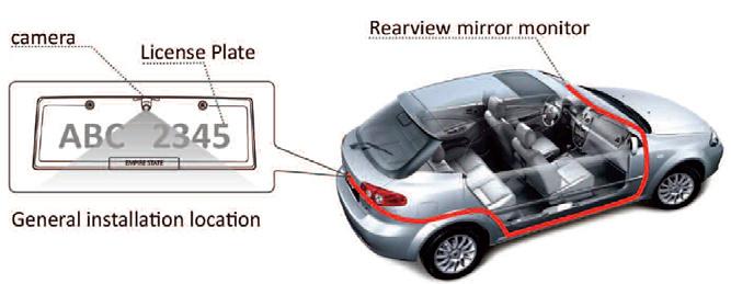
34 Camera Installation CAMERA INSTALLATION Mounting Position installation position 170 º view angle 34
35 No Image On Screen Do a hard reset, unplug all cables and power cables, leave out for 1 minute and then re-connect them Check to ensure that the connection to the camera is tight Verify camera cable is plugged into port labeled Backup Camera Verify that the green positive trigger on power harness is put to power 12v+ Verify camera is on correct camera input Verify cable is connected to monitor Verify camera is connected to cable Connect known working camera and cable to monitor Verify Green trigger is receiving power TROUBLESHOOTING Reverse With Confidence 35
36 ONE YEAR WARRANTY REAR VIEW SAFETY, INC. WARRANTS THIS PRODUCT AGAINST MATERIAL DEFECTS FOR A PERIOD OF ONE YEAR FROM DATE OF PURCHASE. WE RESERVE THE RIGHT TO REPAIR OR REPLACE ANY SUCH DEFECTIVE UNIT AT OUR SOLE DISCRETION. REAR VIEW SAFETY, INC. IS NOT RESPONSIBLE FOR A DEFECT IN THE SYSTEM AS A RESULT OF MISUSE, IMPROPER INSTALLATION, DAMAGE OR MISHANDLING OF THE ELECTRONIC COMPONENTS. REAR VIEW SAFETY, INC. IS NOT RESPONSIBLE FOR CONSEQUENTIAL DAMAGES OF ANY KIND. THIS WARRANTY IS VOID IF: DEFECTS IN MATERIALS OR WORKMANSHIP OR DAMAGES RESULT FROM REPAIRS OR ALTERATIONS WHICH HAVE BEEN MADE OR ATTEMPTED BY OTHERS OR THE UNAUTHORIZED USE OF NONCONFORMING PARTS; THE DAMAGE IS DUE TO NORMAL WEAR AND TEAR, THIS DAMAGE IS DUE TO ABUSE, IMPROPER MAINTENANCE, NEGLECT OR ACCIDENT; OR THE DAMAGE IS DUE TO USE OF THE REAR VIEW SAFETY, INC. SYSTEM AFTER PARTIAL FAILURE OR USE WITH IMPROPER ACCESSORIES. WARRANTY WARRANTY PERFORMANCE DURING THE ABOVE WARRANTY PERIOD, SHOULD YOUR REAR VIEW SAFETY PRODUCT EXHIBIT A DEFECT IN MATERIAL OR WORKMANSHIP, SUCH DEFECT WILL BE REPAIRED WHEN THE COMPLETE REAR VIEW SAFETY, INC. PRODUCT IS RETURNED, POSTAGE PREPAID AND INSURED, TO REAR VIEW SAFETY, INC. OTHER THAN THE POSTAGE AND INSURANCE REQUIREMENT, NO CHARGE WILL BE MADE FOR REPAIRS COVERED BY THIS WARRANTY. WARRANTY DISCLAIMERS NO WARRANTY, ORAL OR WRITTEN, EXPRESSED OR IMPLIED, OTHER THE ABOVE WARRANTY IS MADE WITH REGARD TO THIS REAR VIEW SAFETY, INC. REAR VIEW SAFETY, INC. DISCLAIMS ANY IMPLIED WARRANTY OR MERCHANT-ABILITY OR FITNESS FOR A PARTICULAR USE OR PURPOSE AND ALL OTHER WARRANTIES IN NO EVENT SHALL REAR VIEW SAFETY. INC. LIABLE FOR ANY INCIDENTAL, SPECIAL, CONSEQUENTIAL, OR PUNITIVE DAMAGES OR FOR ANY COSTS, ATTORNEY FEES, EXPENSES, LOSSES OR DELAYS ALLEGED TO BE AS A CONSEQUENCE OF ANY DAMAGE TO, FAILURE OF, OR DEFECT IN ANY PRODUCT INCLUDING, BUT NOT LIMITED TO, ANY CLAIMS FOR LOSS OF PROFITS. 36
37 DISCLAIMER REAR VIEW SAFETY AND/OR ITS AFFILIATES DOES NOT GUARANTEE OR PROMISE THAT THE USER OF OUR SYSTEMS WILL NOT BE IN/PART OF AN ACCIDENT OR OTHERWISE NOT COLLIDE WITH AN OBJECT AND/OR PERSON. OUR SYSTEMS ARE NOT A SUBSTITUTE FOR CAREFUL AND CAUTIOUS DRIVING OR FOR THE CONSISTENT ADHERENCE TO ALL APPLICABLE TRAFFIC LAWS AND MOTOR VEHICLE SAFETY REGULATIONS. THE REAR VIEW SAFETY PRODUCTS ARE NOT A SUBSTITUTE FOR REARVIEW MIRRORS OR FOR ANY OTHER MOTOR VEHICLE EQUIPMENT MANDATED BY LAW. OUR CAMERA SYSTEMS HAVE A LIMITED FIELD OF VISION AND DO NOT PROVIDE A COMPREHENSIVE VIEW OF THE REAR OR SIDE AREA OF THE VEHICLE. ALWAYS MAKE SURE TO LOOK AROUND YOUR VEHICLE AND USE YOUR MIRRORS TO CONFIRM REARWARD CLEARANCE AND THAT YOUR VEHICLE CAN MANEUVER SAFELY. REAR VIEW SAFETY AND/OR ITS AFFILIATES SHALL HAVE NO RESPONSIBILITY OR LIABILITY FOR DAMAGE AND/OR INJURY RESULTING FROM ACCIDENTS OCCURRING WITH VEHICLES HAVING SOME OF REAR VIEW SAFETY PRODUCTS INSTALLED AND REAR VIEW SAFETY AND/ OR ITS AFFILIATES, THE MANUFACTURER, DISTRIBUTOR AND SELLER SHALL NOT BE LIABLE FOR ANY INJURY, LOSS OR DAMAGE, INCIDENTAL OR CONSEQUENTIAL, ARISING OUT OF THE USE OR INTENDED USE OF THE PRODUCT. IN NO EVENT SHALL REAR VIEW SAFETY AND/OR ITS AFFILIATES HAVE ANY LIABILITY FOR ANY LOSSES (WHETHER DIRECT OR INDIRECT, IN CONTRACT, TORT OR OTHERWISE) INCURRED IN CONNECTION WITH THE SYSTEMS, INCLUDING BUT NOT LIMITED TO DAMAGED PROPERTY, PERSONAL INJURY AND/OR LOSS OF LIFE. NEITHER SHALL REAR VIEW SAFETY AND/OR ITS AFFILIATES HAVE ANY RESPONSIBILITY FOR ANY DECISION, ACTION OR INACTION TAKEN BY ANY PERSON IN RELIANCE ON REAR VIEW SAFETY SYSTEMS, OR FOR ANY DELAYS, INACCURACIES AND/OR ERRORS IN CONNECTION WITH OUR SYSTEMS FUNCTIONS. DISCLAIMER Reverse With Confidence 37

38 A Safe Fleet Brand If you have any questions about this product, contact:, Inc Atlantic Avenue Brooklyn, NY Better Cameras. Better Service. IT S OUR GUARANTEE. 38
Instruction Manual. Backup Camera System With Replacement Mirror Display RVS N
 Instruction Manual Backup Camera System With Replacement Mirror Display RVS-778718N Rear View Safety, Inc. 2016 1 NOTE! Please read all of the installation instructions carefully before installing the
Instruction Manual. Backup Camera System With Replacement Mirror Monitor RVS
 Instruction Manual Backup Camera System With Replacement Mirror Monitor RVS-770718 Reverse With Confidence, Inc. 2016 1 TABLE OF CONTENTS Introduction............................... 03 Safety Information..........................
Please read all of the installation instructions carefully before installing the product. Improper installation will void manufacturer s warranty.
 TM 1 What s in the Box? Note: Configuration will vary depending what item options you select. ire 1 Color Sony CCD night vision weather proof backup camera 1 16 Camera Cable 1 Power Connection Wire Table
Instruction Manual. OEM Frameless Rear View Replacement Mirror Monitor with 7.2" Dual Display RVS Reverse With Confidence 1
 Instruction Manual OEM Frameless Rear View Replacement Mirror Monitor with 7.2" Dual Display RVS-718-7 1 NOTE! Please read all of the installation instructions carefully before installing the product.
Instruction Manual. Backup Camera System For Pickup Trucks. RVS-Pickup
 Instruction Manual Backup Camera System For Pickup Trucks RVS-Pickup Rear View Safety, Inc. 2016 1 NOTE! Please read all of the installation instructions carefully before installing the product. Improper
Instruction Manual. G-Series Rear View Replacement Mirror Monitor with 7.3 MirrorLink Display RVS-718-7ML. Rear View Safety, Inc.
 Instruction Manual G-Series Rear View Replacement Mirror Monitor with 7.3 MirrorLink Display RVS-718-7ML Rear View Safety, Inc. 2016 Reverse With Confidence 1 TABLE OF CONTENTS Introduction...............................
Introduction RVS SYSTEMS
 What s in the Box? 1 Split Screen Digital Wireless Monitor with Cigarette Lighter Adaptor 1 CCD Wireless Backup Camera with Power Cable 1 Extendable Suction Cup Mount for Monitor Table of Contents Introduction...4
What s in the Box? REAR VIEW SAFETY
 What s in the Box? 1 x 7" LED Digital Color Monitor 1 x Flush Mount Backup Camera 1 x 66' Camera Cable 1 x Universal Swivel Head Mount 1 x Remote Control 1 x RCA Adaptor 1 x Hole Saw 1 x Screw Kit For
Instruction Manual. Backup Sensor Reversing System RVS-RS103
 Instruction Manual Backup Sensor Reversing System RVS-RS103 RVS Systems, Inc. 2017 TABLE OF CONTENTS System Description............................ 03 Safety Information........................... 04 Before
Vehicle Rear Observation System With Integrated Parking Sensors
 Vehicle Rear Observation System With Integrated Parking Sensors Model: CAMSBAR Installation/User Manual Features: 2.5" LCD Color Display 2 Ultra Sonic Rear Obstacle Sensors On-screen Display Function Automatically
AUTO-BLiP. User Manual Lotus INTELLIGENT DOWNSHIFTS. Version 1.0
 AUTO-BLiP INTELLIGENT DOWNSHIFTS www.auto-blip.com User Manual Lotus Version 1.0 Copyright 2012 Tractive Technology, LLC. All rights reserved. Page 1 WARNING Use of the AUTO-BLiP while driving could lead
AUTO-BLiP. User Manual Porsche INTELLIGENT DOWNSHIFTS. Version 1.2
 AUTO-BLiP INTELLIGENT DOWNSHIFTS www.auto-blip.com User Manual 2005+ Porsche Version 1.2 Copyright 2012 Tractive Technology, LLC. All rights reserved. Page 1 WARNING Use of the AUTO-BLiP while driving
AUTO-BLiP. User Manual Chevrolet Corvette. Version 1.2
 AUTO-BLiP INTELLIGENT DOWNSHIFTS www.auto-blip.com User Manual 1997-2004 Chevrolet Corvette Version 1.2 Copyright 2012 Tractive Technology, LLC. All rights reserved. Page 1 WARNING Use of the AUTO-BLiP
AUTO-BLiP. User Manual Chevrolet Corvette. Version 1.7
 AUTO-BLiP INTELLIGENT DOWNSHIFTS www.auto-blip.com User Manual 2008-2013 Chevrolet Corvette Version 1.7 Copyright 2012 Tractive Technology, LLC. All rights reserved. Page 1 WARNING Use of the AUTO-BLiP
Rearview Mirror with 4" Color LCD Monitor and Camera Package Model: RVMPKG4 (V2.0) User s Manual
 User s Manual") Rearview Mirror with 4" Color LCD Monitor and Camera Package Model: RVMPKG4 (V2.0) User s Manual Features: Rearview Mirror with 4" LCD Monitor Built-In Speaker Rearview Camera Input Auxiliary Video Input
Rearview Mirror with 4" Color LCD Monitor and Camera Package Model: RVMPKG4 (V2.0) User s Manual Features: Rearview Mirror with 4" LCD Monitor Built-In Speaker Rearview Camera Input Auxiliary Video Input
Installation and Users Guide. Plain-Talk. MINI Bluetooth kit with Steering Wheel Controls. Version 2.1
 Installation and Users Guide MINI Bluetooth kit with Steering Wheel Controls Version 2.1 Plain-Talk This product covers all Mini Cooper vehicles as follows: 03/2002-2006 Model Year Mini Cooper and Cooper
AOM452 In-Car LCD Display System Package Installation Manual
 AOM452 In-Car LCD Display System Package Installation Manual Features: 4.5 TFT Color LCD Display Camera 1 input for Rearview camera Camera 2 input for Side view camera Navigation Input Cautions! The product
AUTO-BLiP. User Manual Ford Mustang INTELLIGENT DOWNSHIFTS. Version 1.2
 AUTO-BLiP INTELLIGENT DOWNSHIFTS www.auto-blip.com User Manual 2015-2016 Ford Mustang Version 1.2 Copyright 2012 Tractive Technology, LLC. All rights reserved. Page 1 WARNING Use of the AUTO-BLiP while
AOM-78 7 MONOCHROME OBSERVATION 90 DAY/12 MONTH LIMITED WARRANTY
 BACK COVER FRONT COVER UDIOVOX The Mobile Electronics Company PECIALIZED PPLICATIONS, L.L.C. 90 DAY/12 MONTH LIMITED WARRANTY AUDIOVOX SPECIALIZED APPLICATION, LLC (the company) warrants to the original
Rear Observation System Package Model RVMPKG1 Installation Manual
 Rear Observation System Package Model RVMPKG1 Installation Manual Features: Rearview Mirror with 4 LCD 2 Built in Speakers Rearview Camera Input Auxiliary Video Input Video System Auto Detection for PAL/NTSC
MoistureMatch A next generation grain tester
 MoistureMatch A next generation grain tester A next generation moisture tester incorporating new and unique technology. Finally, a portable tester that will more accurately match and track with the commercial
Woolich Racing. Bike Harness Installation Instructions Suzuki Harness Type 4a GSX1300R (Hayabusa)
") Woolich Racing Bike Harness Installation Instructions Suzuki Harness Type 4a 2013+ GSX1300R (Hayabusa) 1) Introduction To connect your Woolich Racing product to the ECU ( Engine Control Unit or computer)
Woolich Racing Bike Harness Installation Instructions Suzuki Harness Type 4a 2013+ GSX1300R (Hayabusa) 1) Introduction To connect your Woolich Racing product to the ECU ( Engine Control Unit or computer)
ECLIPSE Laundry Dispenser Controller
 ECLIPSE Laundry Dispenser Controller Reference Manual Programming and Operation Online and downloadable Product Manuals and Quick Start Guides are available at www.hydrosystemsco.com Please check online
PVI 1800/PVI Residential/Commercial Grid-Tied Photovoltaic Inverter WARRANTY MANUAL. Subject to Change REV , Solectria Renewables
 PVI 1800/PVI 2500 WARRANTY MANUAL Residential/Commercial Grid-Tied Photovoltaic Inverter 2009, Solectria Renewables Subject to Change REV 10.09 1 Product Warranty & RMA Policy 1.1 Warranty Policy The Solectria
Owner s Guide. Dumbwaiter. Series DUMBWAITER OWNER S GUIDE 1
 Owner s Guide Dumbwaiter Series 007 011 DUMBWAITER OWNER S GUIDE 1 DUMBWAITER OWNER S GUIDE 2 Congratulations on your choice of a Waupaca Elevator, Company, Inc., Dumbwaiter (W.E.C.). Your dumbwaiter is
Woolich Racing. Bike Harness Installation Instructions Hayabusa Gen 2 (08+)
") Woolich Racing Bike Harness Installation Instructions Hayabusa Gen 2 (08+) 1) Introduction To connect your Woolich Racing product to the ECU ( Engine Control Unit or computer) in your bike you need to
Woolich Racing Bike Harness Installation Instructions Hayabusa Gen 2 (08+) 1) Introduction To connect your Woolich Racing product to the ECU ( Engine Control Unit or computer) in your bike you need to
INSTALLATION/OWNERS MANUAL
 INSTALLATION/OWNERS MANUAL XOBP12D PREPARATION Getting Started Thank you for purchasing the Dual Electronics XOBP12D Bandpass Subwoofer System. Although Dual has attempted to make sure all of the information
Installation supplement for. European Integrated Systems, Ltd. Enhanced BMW Bluetooth Interface. Table of Contents
 Table of Contents 1. Introduction 2. BMW Microphone Installation 3. ULF Module and Harness Installation 4. Configuration/Setup 5. Warranty/Disclaimer Information Installation supplement for European Integrated
HBC-20 - LED HIGH BAY
 To prevent death, injury or damage to property, this product must be installed in accordance to National Electrical Code (NFPA70) in the US or Canadian Electrical Code (CSA.) in Canada. Risk of fire or
END USER TERMS OF USE
 END USER TERMS OF USE The following is the End Users Terms of Use as it currently appears in the Mobileye User Manual and Warranty information. This is here for your review and information; it is subject
37SCENE 46SCENE 79SCENE
 Installation and Operation Instructions LED SCENE LIGHT LED SCENE LIGHT 37SCENE 46SCENE 79SCENE 37SCENE 46SCENE Introduction The 37SCENE, 46SCENE, 79SCENE LED Scene Lights are designed for the emergency
110 Volt/12 Volt Portable Inflator
 110 Volt/12 Volt Portable Inflator Owner s Manual WARNING: Read carefully and understand all ASSEMBLY AND OPERATION INSTRUCTIONS before operating. Failure to follow the safety rules and other basic safety
Andatech SOBERPOINT 3. Wall Mounted Breathalyser USER S MANUAL
 Andatech SOBERPOINT 3 Wall Mounted Breathalyser USER S MANUAL Thank you for purchasing an Andatech Soberpoint 3 breathalyser. The Andatech Soberpoint 3 is a Fuel Sensor type coin- or buttonoperated breathalyser.
STC2 Car Kit. Installation Guide
 STC2 Car Kit Installation Guide Box Contents When you unpack your STC2 Car Kit, it should include everything as shown below: Suction Cup Mount & Screws Surface Preparation Cleaning Kit (To clean a surface
BP1204 INSTALLATION/OWNER'S MANUAL
 BP1204 INSTALLATION/OWNER'S MANUAL BP1204 PREPARATION Getting Started Thank you for purchasing the Dual Electronics BP1204 Bandpass Subwoofer System. Although Dual has attempted to ensure the information
12 Volt Heavy-Duty Air Inflator
 12 Volt Heavy-Duty Air Inflator Owner s Manual WARNING: Read carefully and understand all ASSEMBLY AND OPERATION INSTRUCTIONS before operating. Failure to follow the safety rules and other basic safety
SAFETY PRECAUTIONS AND WARNINGS...
 Table of Contents 1. SAFETY PRECAUTIONS AND WARNINGS... 1 2. USING THE TEST TOOL... 2 2.1 TOOL DESCRIPTION... 2 2.2 SPECIFICATIONS... 3 2.3 ACCESSORIES INCLUDED... 3 2.4 GENERAL DESCRIPTION... 4 2.5 POWER...
DUAL WIDEBAND AIR/FUEL RATIO GAUGE Product Numbers: GS-W702W_Dual, GS-C702W_Dual, GS-T702W_Dual
 Installation Instructions Tech Support: 856.768.8300 TechSupport@GlowShiftGauges.com DUAL WIDEBAND AIR/FUEL RATIO GAUGE Product Numbers: GS-W702W_Dual, GS-C702W_Dual, GS-T702W_Dual (1) Gauge (2) Controllers
ELECTRICALLY INSULATED 14mm PROBE
 99 Washington Street Melrose, MA 02176 Phone 781-665-1400 Toll Free 1-800-517-8431 Visit us at www.testequipmentdepot.com ELECTRICALLY INSULATED 14mm PROBE USER S MANUAL NOTE: ETL SAFETY RATING ONLY APPLIES
Thermaltake Warranty / Support Information
 Thermaltake Warranty / Support Information Technical Support Thermaltake is committed to providing the highest quality, most reliable products for our valued customer. There are several ways you may contact
The function of this Dynamic Active Probe has divided into three preferences on the screen main Menus:
 1.0 Introduction: This probe is designed to provide an additional help to automotive technicians in trouble shooting of electrical circuits problems in the car. Apart from using the normal multi tester,
SAVE THESE INSTRUCTIONS
 12 Volt High-V Volume Air Inflator Owner s Manual WARNING: Read carefully and understand all ASSEMBLY AND A OPERATION INSTRUCTIONS before operating. Failure to follow the safety rules and other basic safety
Installation & Operators Manual
 Installation & Operators Manual Model Serial Number Purchase Date 2007-2008 SegVator, LLC Patent Pending All Rights Reserved Important Safety Information Make sure the vehicle has a properly installed
Accessory ACCESSORY User Manual
 AURORA AURORA EXPLORERS Explorers EDITION Edition Accessory ACCESSORY User Manual SiOnyx, LLC 100 Cummings Center, Suite 135P Beverly, MA 01915 (978) 922-0684 support@sionyx.com Follow us on Facebook @SiOnyxNightVision
Angle Grinder Holder
 Angle Grinder Holder Owner s Manual WARNING: Read carefully and understand all ASSEMBLY AND OPERATION INSTRUCTIONS before operating. Failure to follow the safety rules and other basic safety precautions
TALCO FIRE SYSTEMS. LSF Start-Up Instructions. 1) IMPORTANT: Inspect the unit for damage. Report any damage to the freight carrier immediately.
 IMPORTANT: Inspect the unit for damage. Report any damage to the freight carrier immediately.") LSF Start-Up Instructions 1) IMPORTANT: Inspect the unit for damage. Report any damage to the freight carrier immediately. 2) PRE-START-UP: Be sure there is water in the pump. Bleed air at all high points
LSF Start-Up Instructions 1) IMPORTANT: Inspect the unit for damage. Report any damage to the freight carrier immediately. 2) PRE-START-UP: Be sure there is water in the pump. Bleed air at all high points
Plain-Talk Plain-Talk Plus Plain-Talk with Steering Wheel Control
 Installation and Users Guide BMW E46 3-Series Parrot harness adapter kit Version 1.05 Plain-Talk Plain-Talk Plus Plain-Talk with Steering Wheel Control This product covers all E46 3 series vehicles produced
Users Guide for Ac-sync
 Problem solved. Users Guide for Ac-sync Thank you for choosing Anywhere Cart! The AC-SYNC is designed to sync, charge and store 1-36 ipads or tablets. Adjustable device divider bays allow fitment of any
182-LED Solar-Powered Motion Security Light. Owner s Manual
 182-LED Solar-Powered Motion Security Light Owner s Manual WARNING: Read carefully and understand all ASSEMBLY AND OPERATION INSTRUCTIONS before operating. Failure to follow the safety rules and other
User Guide IGD Series
 US User Guide IGD Series DANGER PRIOR TO USE, READ AND UNDERSTAND PRODUCT SAFETY INFORMATION. Failure to follow the instructions may result in ELECTRICAL SHOCK, EXPLOSION, or FIRE, which may result in
DWS404 DWS524 DWS654 DWS684 DWS694. DWS SERIES INSTALLATION/OWNER'S MANUAL Car Audio Speakers
 DWS404 DWS524 DWS654 DWS684 DWS694 DWS SERIES INSTALLATION/OWNER'S MANUAL Car Audio Speakers PREPARATION Safety Guidelines Thank you for purchasing the DWS Series car speakers. Although Dual has attempted
UNIVERSAL GAUGE WIRE HARNESS
 2650-1797-00 UNIVERSAL GAUGE WIRE HARNESS For Installing Auto Meter Electric Speedometer, Tachometer, And Short Sweep Electric Oil Pressure, Water Temperature, Fuel Level, and Volt Meter Gauges. This harness
USER GUIDE 1 USER GUIDE
 USER GUIDE 1 USER GUIDE 1 TABLE OF CONTENTS IN THE BOX...3 NAVIGATING THE MENUS...3 MENU LAYOUT...3 UPDATE YOUR PROGRAMMER...4 CONNECT WITH THE MOTORCYCLE...5 TUNE YOUR MOTORCYCLE...6 ADDITIONAL FEATURES...8
PVI 60KW, PVI 82KW, PVI 95KW
 PVI 60KW PVI 82KW PVI 95KW WARRANTY MANUAL Commercial, Grid-Tied Photovoltaic Inverters 2008, Solectria Renewables LLC Subject to Change DOC-020099 rev 024 1 1 Product Warranty & RMA Policy Warranty Policy
18VDC ESB6 Series Cordless Screwdrivers Operation Manual
 18VDC ESB6 Series Cordless Screwdrivers Screwdriver Models : ESB6-8, ESB6-12, ESB6-15, ESB6-22 CAUTION - Please read, understand, and follow all operating and safety instructions in this manual before
ROTARY HEAD DIGITAL STEM THERMOMETER
 ROTARY HEAD DIGITAL STEM THERMOMETER 99 Washington Street Melrose, MA 02176 Phone 781-665-1400 Toll Free 1-800-517-8431 Visit us at www.testequipmentdepot.com DT340RH Please read this manual carefully
30 Inch x 18 Inch Service Cart
 30 Inch x 18 Inch Service Cart Owner s Manual WARNING: Read carefully and understand all ASSEMBLY AND OPERATION INSTRUCTIONS before operating. Failure to follow the safety rules and other basic safety
Owner s Installation Guide
 Owner s Installation Guide Introduction The nophoto is a highly advanced smart detterent device designed to protect your license plate from flash photography. Using patented technology, the nophoto reacts
Nature Power Inverters. True Sinewave Inverter Modified Sinewave Inverter. Owner s Manual
 Version 1.1 Version 2 Nature Power Inverters True Sinewave Inverter Modified Sinewave Inverter Owner s Manual!!!!!!!!!!! 38304 38204 For safe and optimum performance, the Power Inverter must be used properly.
EZ-R7 T-Plug. Universal 7-Pin Heavy Duty Plug For Vehicles equipped with 7-Way Trailer Connectors. Installation Instructions and Product Warranty
 EZ-R7 T-Plug Universal 7-Pin Heavy Duty Plug For Vehicles equipped with 7-Way Trailer Connectors Installation Instructions and Product Warranty Professional Installation Required Thank you for purchasing
Aftermarket Helio Installation Guide. Version 1.0.2
 Aftermarket Helio Installation Guide Version 1.0.2 Date: 9/30/2015 ID: aftermarket-helio-install Number of Pages: 9 File Name: 150930_aftermarket-helio-install_V1.0.2 Revision History Configuration Item
SUNTURA SOLAR TRACKER
 WindyNation SUNTURA SOLAR TRACKER SOT-TRKS-NF User s Manual Page 1 of 10 WindyNation 08/09/2012 Table of Contents 1 Introduction... 3 1.1 Limited Warranty... 3 1.2 Restrictions... 3 1.3 Warranty Claims
Owner s Manual. IS0250a. ecr7106 9/2007
 TM Owner s Manual IS0250a ecr7106 9/2007 TABLE OF CONTENTS Part I: Introduction 3 Basic Operation 4 Part II: System Setup 6 Input Setup 6 Tank Setup 8 Depth Setup 9 Part III: Operating Instructions 10
EZ Carrier 3. Owner s Manual. Keep instructions for future reference
 EZ Carrier vv Owner s Manual Keep instructions for future reference Introduction The EZ Carrier provides all the flexibility you may need to transport your mobility scooter. The features include: The capability
230VAC Power Inverter 400W Owner s Manual
 400W 230VAC Power Inverter 400W Owner s Manual For safe and optimum performance, the Enerdrive epower Inverter must be used properly. Carefully read and follow all instructions and guidelines in this manual
SELECT -24 INSTALLATION GUIDE. INST036 Doc 2.02
 SELECT -24 INSTALLATION GUIDE INST036 Doc 2.02 CONTENTS General Information...2 Select-24 Diagram...3 Mounting the Select Controller...4 Dual Pole Nosebox Installation...5 Aux Harness Installation...6
Premium OEM Style 4.3 Replacement Mirror Monitor
 Premium OEM Style 4.3 Replacement Mirror Monitor RVM-043A User Manual Thank you for purchasing Parkmate s RVM-043A Premium OEM Style 4.3 Replacement Rear View Mirror Monitor. This state of the art Parkmate
1000-LB. MOTORCYCLE LIFT TABLE OWNER S MANUAL
 1000-LB. MOTORCYCLE LIFT TABLE OWNER S MANUAL WARNING: Read carefully and understand all ASSEMBLY AND OPERATION INSTRUCTIONS before operating. Failure to follow the safety rules and other basic safety
MICROCARE 3 PHASE INVERTER MANUAL
 3 PHASE INVERTER MANUAL 1 Contents 1. INTRODUCTI... 3 2. SAFETY INSTRUCTI... 4 3. SYSTEM DESCRIPTI... 6 4. WIRING DIAGRAM... 9 5. INVERTER OPERATI... 10 6. INVERTER CLUSTER PROGRAMMING... 13 7. CLUSTER
WARRANTY POLICY. Grid-Tied Photovoltaic Inverters. Revision D. 2014, Solectria Renewables, LLC DOCIN
 WARRANTY POLICY Revision D 2014, Solectria Renewables, LLC DOCIN-070360 1 Product Warranty & RMA Policy 1. Warranty Policy Warranty Registration: It is important to have updated information about the inverter
DIRECT PLUS/FLEX/MAX INSTALLATION GUIDE. INST165 Doc 1.04
 DIRECT PLUS/FLEX/MAX INSTALLATION GUIDE INST165 Doc 1.04 CONTENTS General Information...2 Diagrams...3 Mounting the Direct Nosebox...5 Main Harness Installation...6 Interior Light Harness Installation...10
User Manual. Posture+ Adjustable Base. For customer service call:
 User Manual Posture+ Adjustable Base For customer service call: 1-877-707-7533 1 IMPORTANT INFORMATION PLEASE READ THESE INSTRUCTIONS THOROUGHLY BEFORE USING THIS PRODUCT. PROPER OPERATION OF YOUR ADJUSTABLE
WiFi Tank Level Monitor Installation Instructions
 WiFi Tank Level Monitor Installation Instructions COMPATIBILITY To install the Tank Utility remote level monitor, you will need the following: A WiFi connection at your tank site An Apple or Android smartphone
55-Gallon Drum Cradle
 55-Gallon Drum Cradle Owner s Manual WARNING: Read carefully and understand all ASSEMBLY AND OPERATION INSTRUCTIONS before operating. Failure to follow the safety rules and other basic safety precautions
1000-lb Hydraulic Truck Crane
 1000-lb Hydraulic Truck Crane Owner s Manual WARNING: Read carefully and understand all ASSEMBLY AND OPERATION INSTRUCTIONS before operating. Failure to follow the safety rules and other basic safety precautions
Components. Options Accessory Harness USB Charger. Quick Connector. Hook & Loop / Cable-ties. RFID Antenna. Module. Main Harness.
 SRX SERIES Table of Contents - Components - Planning The Install - Mounting - Switched Power - Attach Accessory Harness - Plug In Module - Back-Up Battery - Remote Encoding - 2-Way RFID Remote User Instructions
CAPACITOR ACTUATED PORTABLE STARTER CAPS USER GUIDE. INST048 Doc 3.01
 CAPACITOR ACTUATED PORTABLE STARTER CAPS USER GUIDE INST048 Doc 3.01 CONTENTS General Information...2 Charts...3 Before First Use...4 Safety Requirements...5 What to Expect from the CAPS...5 CAPS Diagram...6
Pressure Roller with 24-inch Fixed Extension - For application of architectural paints and coatings -
 Instructions Important Safety Instructions Read all warnings and instructions in this manual. Save these instructions. 311082D Pressure Roller with 24-inch Fixed Extension - For application of architectural
Heavy-Duty Sawhorse. Owner s Manual
 Heavy-Duty Sawhorse Owner s Manual WARNING: Read carefully and understand all ASSEMBLY AND OPERATION INSTRUCTIONS before operating. Failure to follow the safety rules and other basic safety precautions
A/C PRESSURE MONITOR INSTALLATION INSTRUCTIONS SYSTEM OPERATION GREEN INDICATOR LIGHT
 A/C PRESSURE MONITOR INSTALLATION INSTRUCTIONS Do not attempt to clean or inspect anything while the engine is running. Cleaning and inspection must be done by a certified mechanic. All A/C service must
Do not install and/or operate this safety product unless you have read and understand the safety information contained in this manual.
 Installation and Operation Instructions MR Tri- Light Available in various color combinations, the MR Directional LED surface mount, tri-color warning light is ideal for a wide variety of auxiliary warning
Model AS-RC3260 TV Cart. Rolling Cart for Audio Mount System & Flat Panel TVs
 Model AS-RC3260 TV Cart Rolling Cart for Audio Mount System & Flat Panel TVs GETTING STARTED Introduction Congratulations on the purchase of your new Helios AS-RC3260 Rolling Cart. For maximum benefit,
120-LED Solar-Powered Motion Security Light
 120-LED Solar-Powered Motion Security Light Owner s Manual WARNING: Read carefully and understand all ASSEMBLY AND OPERATION INSTRUCTIONS before operating. Failure to follow the safety rules and other
RV-10 Center Arm Rest Console
 RV-10 Center Arm Rest Console Important Notice: This manual contains important information that may affect the safety of your aircraft. Read the Warranty / Agreement below. There is information in the
For additional technical tips, please visit
 NOTICE OF INTENDED INSTALLATION AND USE THE ROSEN MULTI-MEDIA NAVIGATION SYSTEMS CONTAIN AN INTERNAL VIDEO PLAYER, WHICH IS NOT INTENDED FOR VIEWING BY THE DRIVER. THE VIDEO PLAYER IS DISABLED WHEN THE
Wiring Installation Instructions for : Pressure. Wiring Installation Instructions for : Temperature. 2 1/16 Spek Pro Professional Racing Gauge
 Wiring Installation Instructions for : Pressure DIAGRAM 1 Pressure Sensor 1/8 NPT 3 AMP Wiring Installation Instructions for : Temperature GAUGE 12-Pin Wiring Harness & Plug Firewall Grommet DIAGRAM 2
Thank you for choosing Mobileye.
 Thank you for choosing Mobileye. You have joined thousands of customers in the world, who have also chosen the Mobileye 5-Series systems. You are now helping to turn our environment into a safer one for
WARNING. Laser light is extremely bright and can potentially cause permanent eye damage or interfere with critical operations if improperly used.
 TG7630G / TG7630R TRUGLO, Inc. 525 International Parkway RICHARDSON, TEXAS 75081 MADE IN CHINA Green Laser: POWER OUTPUT
Transmission Guardian
 Transmission Guardian Thank you for purchasing the Transmission Guardian from Bowler Performance Transmissions. We hope you are 100 percent satisfied with your purchase and if for any reason you are not,
600 Amp Battery Jumper with Air Compressor
 Item #2509 600 Amp Battery Jumper with Air Compressor User s manual- Read these instructions before using the unit Features Front LED Worklight Worklight Switch USB Power Ports and on/off Switch 12V DC
Low Profile Creeper. Owner s Manual
 Low Profile Creeper Owner s Manual WARNING: Read carefully and understand all ASSEMBLY AND OPERATION INSTRUCTIONS before operating. Failure to follow the safety rules and other basic safety precautions
Bio-Pump Plus. Operating Instructions. Product # ZBP-200. Description. Specifications
 Bio-Pump Plus Product # ZBP-200 Operating Instructions Description The Bio-Pump Plus is an advanced portable, battery powered air sampling pump designed for the exclusive use with Air-O-Cell,Via-Cell,
18VDC ESB6-X Series Cordless Screwdrivers Operation Manual
 18VDC ESB6-X Series Cordless Screwdrivers Screwdriver Models : ESB6-X3.5, ESB6-X3.5F, ESB6-X5F ESB6-X6, ESB6-X9, ESB6-X12 CAUTION - Please read, understand, and follow all operating and safety instructions
NORMAL/DIAL BRIGHTNESS: Press the down or up button to adjust dial brightness. Press the center button to save and advance to PEAK PLAYBACK.
 Flow Chart Programming Instructions for : VOLTMETER 2 1/16 Program Main Menu (Press one button at a time) START HERE Main Menu ONE NORMAL/DIAL BRIGHTNESS: Press the down or up button to adjust dial brightness.
7.3L POWERSTROKE BANJO BOLT KIT Fits L Powerstroke Diesel. Installation Guide
 7.3L POWERSTROKE BANJO BOLT KIT Fits 94-03 7.3L Powerstroke Diesel Installation Guide INSPECT CONTENTS OF THIS KIT THOROUGHLY BEFORE STARTING THE INSTALLATION PROCESS! IF YOU FIND A PROBLEM WITH YOUR PACKAGE:
Installation and Operation Instructions Safety Director Arrow
 Installation and Operation Instructions Safety Director Arrow! WARNING! Failure to install or use this product according to manufacturers recommendations may result in property damage, serious bodily/personal
Thermometer models 02023/02028/02053/02054
 Instruction Manual Thermometer models 02023/02028/02053/02054 CONTENTS Unpacking Instructions... 2 Package Contents... 2 Product Registration... 2 Features & Benefits... 3 Setup... 4 Set the Time & Units...
Electric Chainsaw Sharpener With Bar Mount
 Electric Chainsaw Sharpener With Bar Mount Owner s Manual WARNING: Read carefully and understand all ASSEMBLY AND OPERATION INSTRUCTIONS before operating. Failure to follow the safety rules and other basic
6-TON DOUBLE LOCKING JACK STANDS OWNER S MANUAL
 6-TON DOUBLE LOCKING JACK STANDS OWNER S MANUAL WARNING: Read carefully and understand all ASSEMBLY AND OPERATION INSTRUCTIONS before operating. Failure to follow the safety rules and other basic safety
Owner's Manual. For latest instructions please go to
 mycharge name and logo are registered trademarks of RFA Brands. 2012-2013 RFA Brands. All Rights Reserved. Patent Pending. Made in China. IB-RFAM0232 Owner's Manual For latest instructions please go to