DIRECT PLUS/FLEX/MAX INSTALLATION GUIDE. INST165 Doc 1.04
|
|
|
- Christina Flowers
- 5 years ago
- Views:
Transcription

1 DIRECT PLUS/FLEX/MAX INSTALLATION GUIDE INST165 Doc 1.04
2
3 CONTENTS General Information...2 Diagrams...3 Mounting the Direct Nosebox...5 Main Harness Installation...6 Interior Light Harness Installation...10 Severe Service Installation (Max Only)...11 Installing Cables to the Nosebox...11 Mounting the Switch...12 Routing the Severe Service Cables...14 Part List...18 Limited Commercial Warranty Policy...24 P: F:
4 GENERAL INFORMATION The Purkeys Direct nosebox system combines all the best features of our original liftgate charging systems with a spacesaving nosebox that helps standardize the front of the trailer. It also includes an interior light controller (harness sold seperately) designed to turn the lights on inside a trailer and automatically shut them off either: via a timer if the liftgate batteries drop to a low state of charge. The Direct improves the charging of liftgate batteries by utilizing a DC/DC Converter to boost the voltage for optimal charging. The boost in voltage overcomes the normal voltage drop caused by the extended distance between the liftgate batteries and the vehicle charging system. Also, in cold temperatures batteries require increased charging voltages to maintain a high state of charge. The DC/DC Converter in the Direct system compensates for temperature as well as for voltage drop and provides the best voltage to the remotely located liftgate batteries. The result is well-charged liftgate batteries that will last longer and have ample power for liftgate operation. The Direct nosebox system is automatic and has easy to interpret LED indicators to assure drivers and technicians of proper system function. The LED indicators clearly show the status of the source as well as the status of the liftgate batteries. A quick glance at the Direct Controller assures the driver that the liftgate batteries are ready to go, or alerts the driver that the batteries need maintenance. 2


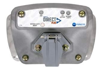
5 DIRECT NOSEBOX INSTALLATION GUIDE DIAGRAMS DIRECT PLUS DIRECT FLEX P: F:


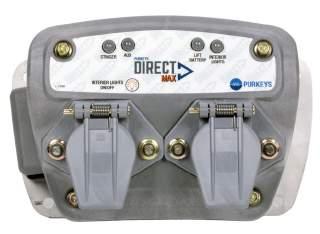
6 DIRECT MAX Direct Max Side Panel ON/OFF SWITCH 4


7 DIRECT NOSEBOX INSTALLATION GUIDE MOUNTING THE DIRECT NOSEBOX Step 1: Mount the Direct nosebox at the front of the trailer via the mounting holes on the mounting plate. Note: Do not block the LED status decal on the side of the Direct when mounting the nosebox. Note: The Direct Plus nosebox must be mounted with the wires facing down to help prevent water intrusion. Direct Contoller Mounting Complete. P: F:


8 MAIN HARNESS INSTALLATION Step 1: Route the Direct jacketed 4-conductor main harness for the DC/DC converter behind the front plate, then behind the header plate through the air/electrical tube to the center channel. Step 2: Route the Direct jacketed 4-conductor main harness in the center channel toward the back of the trailer. Secure with wire ties or cable clamps as you go. Note: Place the cable clamps along the 4-conductor jacketed main harness every 6 inches to ensure proper support for the cable. Avoid sharp edges and possible chaffing points. Step 3: Once you are near the liftgate battery box, begin routing the Direct jacketed 4-conductor main harness into the liftgate battery box through a dome nut or rubber grommet. Note: Ensure that the jacketed 4-conductor main harness enters the liftgate battery box through a dome nut or rubber grommet to prevent chaffing the harness, which could result in possible electrical short in the system. 6


, and cut off")
9 DIRECT NOSEBOX INSTALLATION GUIDE Step 4: Position the Direct jacketed 4-conductor main harness so it will reach the 2-stud strip and all the slack has been taken up. Mark the jacketed 4-conductor main harness so it can be taken back out of the battery box to be terminated. Note: If your battery box includes a slide-out tray, include enough slack to allow the tray to fully extend without tugging the wire connections. Step 5: Pull the jacketed 4-conductor main harness out of the box (making it easier to work on), and cut off the excess at the mark. Step 6: Cut about 8 inches off the jacketed portion of the 4 wires. P: F:


10 Step 7: Apply the supplied 3/4 inch black heat shrink where the jacket was stripped off. Step 8: Strip 3/8 inch of insulation off all 4 wires. Step 9: Slide the supplied red 1/4 inch heat shrink over the orange, yellow, and black wires. Slide the supplied black 1/4 inch heat shrink over the white wire. Step 10: Crimp 3/8 ring terminals onto the white and black 8-gauge wires. Crimp #10 ring terminals onto the 14-gauge orange and 16-gauge yellow wires. 8

 stud. Connect the 16-gauge yellow wire to the ignition stud.")
11 DIRECT NOSEBOX INSTALLATION GUIDE Step 11: Position the heat shrink over the crimps and apply heat to the 4 terminals. Step 12: Re-route the jacketed 4-conductor main harness back into the battery box. Connect the 8-gauge black wire to the red positive input stud. Connect the 8-gauge white wire to the black ground stud. Connect the 14-gauge orange wire to the liftgate (+) stud. Connect the 16-gauge yellow wire to the ignition stud. Main Harness Installation Complete. P: F:

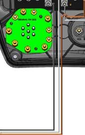
12 INTERIOR LIGHT HARNESS INSTALLATION These instructions only apply if you have purchased the interior light harness. Step 1: Route Interior Light Input Harness into the nosebox. Step 2: Terminate the positive input with a #10 ring terminal and connect to the stud that has the fuse holder hooked to it. (See point B on the diagram below.) Step 3: Terminate the wire that will output to the interior lights (Interior Light Power Cable, which we don t provide) with a #10 ring terminal and connect the positive output to the stud that has the blue wire. (See point A on the diagram below.) Step 4: Connect both input and output grounds to ground. 10


13 DIRECT NOSEBOX INSTALLATION GUIDE SEVERE SERVICE INSTALLATION (MAX ONLY) Installing Cables to the Nosebox Step 1: Remove cover on the side of the DIRECT MAX. Step 2: Install 4-gauge cables as shown. Replace side cover. Step 3: Route the 4-gauge red and black cables behind the front cover, then under the header plate through the air/ electrical tube to the center channel. Important: Avoid sharp edges and possible chaffing points. Installation Complete. P: F:


14 Mounting the Switch Step 1: Mount the 1-2 Switch to the inside of the liftgate battery box using the existing pre-drilled holes. Note: If the 1-2 Switch mounting holes do not exist, use the 1-2 Switch as a template to drill these holes. Step 2: Install flat washers on 2 inch bolts before pushing the bolts through the plastic or metal wall of the battery box. Step 3: Mount the 1-2 Switch using the provided hardware. Step 4: Push the bolts through the battery box. 12

, install the nut, and Note: Make sure to slide")
 to the liftgate")
15 DIRECT NOSEBOX INSTALLATION GUIDE Step 5: Add flat washers, lock washers, and nuts to the bolts and tighten. Step 6: Connect the short red 4-gauge cable marked right side circuit breaker from the 1-2 Switch to the right side of the circuit breaker (toward door), install the nut, and tighten. Note: Make sure to slide the red boot over this connection to protect it from a short. Step 7: Connect the 4-gauge red wire from the 1-2 Switch marked Liftgate Battery (+) to the liftgate battery positive post. Install nut and tighten. Installation Complete. P: F:


 to terminate the cables.")
16 Routing the Severe Service Cables Step 1: Route the red and black 4-gauge cable toward the back of the trailer via the center channel. Secure with wire ties as you go. Important: Avoid sharp edges and possible chaffing points. Step 2: When near the liftgate battery box, route the two 4-gauge red and black cables to the liftgate battery box. Again, secure the cables with wire ties as you go. Step 3: Deterimine if the pre-terminated cables are an appropriate length. If they are, skip to Step 9. If they are not the approriate length, continue to Step 4. Use the supplied hardware (BK-1055) to terminate the cables. Step 4: Mark how much excess will need to be cut off of the 4-gauge 40 ft red and black cables so that the 4-gauge red cable will reach the left side of the 150 amp circuit breaker and the 4-gauge black cable will reach the liftgate battery negative post. 14


17 DIRECT NOSEBOX INSTALLATION GUIDE Step 5: Pull the 4-gauge red and black cables back out of the battery box so it is easier to work on them. Cut off the excess. Step 6: Strip 1/2 inch of the insulation off the 4-gauge red and black cables. Step 7: Install the 1/4 inch ring terminal on the 4-gauge red cable and the 3/8 inch ring terminal on the black cable. Crimp the connections. Step 8: Install the red heat shrink to the crimp area of the red cable and the black heat shrink to the crimp area of the black cable. Apply heat to both pieces to seal the connection. P: F:


18 Step 9: Route the two 4-gauge red and black cables back into the liftgate battery box. Connect the 4-gauge black cable to the liftgate battery negative post. Step 10: Slide the supplied red rubber boot over the 4-gauge red cable and connect this cable to the left side of the 150 amp circuit breaker. Installation Complete. 16
19 NOTES DIRECT NOSEBOX INSTALLATION GUIDE P: F:
20 PART LIST: DIRECT PLUS PART# F AMP MIDI FUSE PART# BK-1054 HARDWARE BAG KIT PART# BK-1049 TERMINAL BAG KIT PART# DF00094 DIRECT PLUS COVER ASSEMBLY 18


21 DIRECT NOSEBOX INSTALLATION GUIDE PART# MOD00094-K DIRECT, PLUS NOSEBOX PART# NB00041 RECEPTACLE, NYLON 7-WAY WITH #10-32 STUDS - SOLID PINS PART# H FT MAIN HARNESS PART# H FT MAIN HARNESS PART# H FT MAIN HARNESS P: F:


22 PART# PLUS-25 DIRECT PLUS NOSEBOX, 25 FT PART# PLUS-50 DIRECT PLUS NOSEBOX, 50 FT PART# PLUS-70 DIRECT PLUS NOSEBOX, 70 FT PART# INST165 DIRECT PLUS, FLEX, MAX INSTALLATION GUIDE 20
23 DIRECT NOSEBOX INSTALLATION GUIDE PART LIST: DIRECT FLEX PART# F AMP MIDI FUSE PART# BK-1054 HARDWARE BAG KIT PART# BK-1049 TERMINAL BAG KIT PART# DF00095 DIRECT FLEX COVER ASSEMBLY P: F:
24 PART# MOD00095-K DIRECT FLEX NOSEBOX PART# NB00041 RECEPTACLE, NYLON 7-WAY WITH #10-32 STUDS - SOLID PINS PART# NB00048 RECEPTACLE, NYLON DUAL POLE 22


25 DIRECT NOSEBOX INSTALLATION GUIDE PART# H FT MAIN HARNESS PART# H FT MAIN HARNESS PART# H FT MAIN HARNESS PART # FLEX-25 DIRECT FLEX NOSEBOX, 25 FT PART # FLEX-50 DIRECT FLEX NOSEBOX, 50 FT PART # FLEX-70 DIRECT FLEX NOSEBOX, 70 FT PART# INST165 DIRECT PLUS, FLEX, MAX INSTALLATION GUIDE P: F:

26 PART LIST: DIRECT MAX PART# F00024 FUSE, 150 AMP MEGA PART# F AMP MIDI FUSE PART# BK-1054 HARDWARE BAG KIT PART# BK-1049 TERMINAL BAG KIT 24


27 DIRECT NOSEBOX INSTALLATION GUIDE PART# BK-1055 SELECT/DIRECT BYPASS BAG KIT PART# DF00096 DIRECT MAX COVER ASSEMBLY PART# MOD00096-K DIRECT MAX NOSEBOX P: F:
28 PART# NB00041 RECEPTACLE, NYLON 7-WAY WITH #10-32 STUDS - SOLID PINS PART# NB00048 RECEPTACLE, NYLON DUAL POLE PART# H FT MAIN HARNESS PART# H FT MAIN HARNESS PART# H FT MAIN HARNESS 26


29 DIRECT NOSEBOX INSTALLATION GUIDE PART# CA00136-SW SEVERE SERVICE TRAILER LINK 53FT, 4 AWG WITH SWITCH PART# CA00138-SW SEVERE SERVICE TRAILER LINK 23FT, 4 AWG WITH SWITCH PART# CA00170-SW SEVERE SERVICE TRAILER LINK 70FT, 4 AWG WITH SWITCH PART# MAX-25 DIRECT MAX NOSEBOX, 25 FT PART# MAX-50 DIRECT MAX NOSEBOX, 50 FT PART# MAX-70 DIRECT MAX NOSEBOX, 70 FT P: F:

30 PART# B00036 STUD, BRASS FOR MEGA FUSE WITH 1/4-20 THREADS PART# INST165 DIRECT PLUS, FLEX, MAX INSTALLATION GUIDE 28
31 DIRECT NOSEBOX INSTALLATION GUIDE LIMITED COMMERCIAL WARRANTY POLICY Purkeys Fleet Electric, Inc. (hereafter Purkeys ), warrants each product to be free of defects in material or workmanship under normal use and service. This warranty is for the benefit of Original Equipment Manufacturers, Dealers, Warehouse Distributors, Fleets, or other End Users (hereafter Customers ) and covers products manufactured by Purkeys and sold new to Customers either directly by Purkeys or by its authorized dealers, distributors, or agents. The length of the Warranty Period is 24 months. The warranty period commences on the in-service or install date and is not transferable. Failure to provide the in-service or install date on the warranty claim form will cause the warranty period to begin on the date the part was manufactured or date of sale recorded on the original sales invoice, whichever is earlier. A completed warranty claim form should accompany all parts submitted to Purkeys for consideration for repair or replacement under warranty. The submitted claim form should contain all of the information required. Lack of a properly or fully completed claim form will result in delay or denial of warranty claim. Claims must be submitted no later than 30 days after part is removed. This warranty does not apply if, in sole judgement of Purkeys, the product has been damaged or subjected to accident, faulty repair, improper adjustment, improper installation or wiring, neglect, misuse, or alteration or if the product failure is caused by defects in peripheral vehicle components or components attached to the Product or failure of a part not manufactured by Purkeys. This warranty shall not apply if any Purkeys product is used for a purpose for which it is not designed or is in any way altered without the specific prior written consent of Purkeys. ANY Product alleged by a Customer to be defective must be inspected by Purkeys as a part of the warranty claims process in order to confirm that the part has failed as a result of a defect in material or workmanship. Transportation for products and parts submitted to Purkeys for warranty consideration must be prepaid by Customer. Repaired or replaced products and or components will be returned to Customer pre-paid by Customer or freight collect to the address provided by Customer in the warranty claim form. No charge will be made for labor or material in effecting such repairs. The Warranty provided by Purkeys hereunder is specifically limited to repair or replacement of the Product as Purkeys deems most appropriate in its sole discretion. Purkeys neither assumes nor authorizes any other person to assume on its behalf any other warranty or liabilities in connection with Purkeys products. The Warranty does not apply to fuses or other consumable or maintenance items which are or may be a part of any Purkeys product. THIS WARRANTY DOES NOT APPLY TO LOSS OF VEHICLE OR EQUIPMENT, LOSS OF TIME, INCONVENIENCE, OR OTHER INCIDENTAL OR CONSEQUENTIAL DAMAGES. PURKEYS SPECIFICALLY DISCLAIMS AND SHALL NOT BE LIABLE FOR INCIDENTAL OR CONSEQUENTIAL DAMAGES arising out of or from the use of Purkeys products by the Customer. THIS LIMITED WARRANTY IS IN LIEU OF ALL OTHER WARRANTIES, INCLUDING COMMON LAW WARRANTIES OF FITNESS FOR A PARTICULAR PURPOSE, MERCHANTABILITY, AND ANY OTHER EXPRESS OR IMPLIED WARRANTIES. ALL OTHER SUCH WARRANTIES ARE SPECIFICALLY DISCLAIMED. This Limited Commercial Warranty supersedes all previous Warranty Policies issued by Purkeys and any of its suppliers. P: F:
32
SELECT -24 INSTALLATION GUIDE. INST036 Doc 2.02
 SELECT -24 INSTALLATION GUIDE INST036 Doc 2.02 CONTENTS General Information...2 Select-24 Diagram...3 Mounting the Select Controller...4 Dual Pole Nosebox Installation...5 Aux Harness Installation...6
SOLAR BOLT CHARGING SYSTEM INSTALLATION GUIDE
 CHARGING SYSTEM Doc 1.00 INST052 1 SOLAR BOLT CHARGING SYSTEM CONTENTS General Information... 2 Solar Panel Installation... 3 Solar Bolt Main Harness and Indicate Installation... 4 Cable Routing... 9 Solar
SOLAR DASH CHARGING SYSTEM USER GUIDE
 SOLAR DASH CHARGING SYSTEM Doc 1.01 INST049 INSTALLATION STEP 1 Place 20 watt solar panel in the dash of the vehicle facing up. Note: For ideal results position the vehicle in a manner in which the solar
SELECT/DIRECT DEMO BOX USER GUIDE. INST164 Doc 1.00
 SELECT/DIRECT DEMO BOX USER GUIDE INST164 Doc 1.00 CONTENTS Using the Demo Box...2 Direct Dual Pole (Stinger) Demonstration...5 Select Dual Pole, Reefer, or Aux Demonstration...6 Switch Board Callouts...7
SELECT DIAGNOSTIC GUIDE. INST028 Doc 3.02
 SELECT DIAGNOSTIC GUIDE INST028 Doc 3.02 CONTENTS General Information...2 Select Call-Outs...3 Wire Diagram and Legend...4 Diagnostics...6 Excessive Voltage Drop Diagnostics...6 Static Diagnostics...7
INVERTER HARNESS INSTALLATION FOR FREIGHTLINER CASCADIA
 FOR FREIGHTLINER CASCADIA Part #: P808 1004FC 08/05/2014 Doc 1.04 INST065 Page 1 Step 1: Unpack the plate assembly and both positive and negative cables. INSTALLATION INSTRUCTIONS Step 2: Insert the negative
CAPACITOR ACTUATED PORTABLE STARTER CAPS USER GUIDE. INST048 Doc 3.01
 CAPACITOR ACTUATED PORTABLE STARTER CAPS USER GUIDE INST048 Doc 3.01 CONTENTS General Information...2 Charts...3 Before First Use...4 Safety Requirements...5 What to Expect from the CAPS...5 CAPS Diagram...6
DIRECT-04 V1.10 OWNER S MANUAL MAXON #
 MAXON # 295972-500 1 DIRECT-04 V1.10 DIRECT FOR STRAIGHT TRUCK OR REEFER APPLICATION CONTENTS General Information... 2 Direct-04 Diagram for Straight Truck... 3 Direct-04 Diagram for Reefer... 4 Direct
SELECT-32 V1.10 OWNERS MANUAL MAXON#
 MAXON# 296170-500 1 SELECT DUAL POLE COMBINATION, REEFER AND 7 WAY OPTION CONTENTS General Information...2 Select-32 Diagram...3 Select Controller Mounting Instructions...4 Dual/Single Nose Box Installation...5
TRAILER AUXILIARY POWER SYSTEM (TAPS) INSTALLATION GUIDE V1.10
 INSTALLATION GUIDE V1.10") TRAILER AUXILIARY POWER SYSTEM (TAPS) INSTALLATION GUIDE V1.10 TAPS INSTALLATION GUIDE V1.10 1 TRAILER AUXILIARY POWER SYSTEM CONTENTS General Information and System Logic... 2 Diagrams... 3 System Diagram
TRAILER AUXILIARY POWER SYSTEM (TAPS) INSTALLATION GUIDE V1.10 TAPS INSTALLATION GUIDE V1.10 1 TRAILER AUXILIARY POWER SYSTEM CONTENTS General Information and System Logic... 2 Diagrams... 3 System Diagram
1200+ WITH LVD (LOW VOLTAGE DISCONNECT) USER GUIDE
 USER GUIDE") 1200+ WITH LVD (LOW VOLTAGE DISCONNECT) USER GUIDE INST045 Doc 2.00 CONTENTS General Information...2 Operating Environment...6 Features...7 Installation Instructions...8 Inverter Ground and Remote Sense
1200+ WITH LVD (LOW VOLTAGE DISCONNECT) USER GUIDE INST045 Doc 2.00 CONTENTS General Information...2 Operating Environment...6 Features...7 Installation Instructions...8 Inverter Ground and Remote Sense
1200+ WITH LVD (LOW VOLTAGE DISCONNECT) V1.00 OWNERS MANUAL
 V1.00 OWNERS MANUAL") 1200+ WITH LVD (LOW VOLTAGE DISCONNECT) V1.00 1 1200+ WITH LVD V1.00 OWNERS MANUAL CONTENTS General Information... 2 Operating Environment... 5 Features... 6 Installation Instructions... 7 Inverter Ground
1200+ WITH LVD (LOW VOLTAGE DISCONNECT) V1.00 1 1200+ WITH LVD V1.00 OWNERS MANUAL CONTENTS General Information... 2 Operating Environment... 5 Features... 6 Installation Instructions... 7 Inverter Ground
1200+ WITH TIMER V1.00 OWNERS MANUAL
 1200+ WITH TIMER V1.00 1 1200+ WITH TIMER V1.00 OWNERS MANUAL CONTENTS General Information... 2 Operating Environment... 5 Features... 6 Installation Instructions... 7 Inverter Ground and Remote Sense
For electronically controlled E4OD and 4R100 automatic transmissions ** READ ALL INSTRUCTIONS BEFORE INSTALLATION **
 26 August 2005 Ford PressureLoc #1060380 1 BD Ford PressureLoc Installation Manual For electronically controlled E4OD and 4R100 automatic transmissions Part#: 1060380 ** READ ALL INSTRUCTIONS BEFORE INSTALLATION
Part# Accessory Power Distribution Module
 7 February 2006 Power Pod (1038800) Page 1 BD Powe r Pod Installation Instructions Part# 1038800 Accessory Power Distribution Module Power Pod Specifications: Eliminate multiple T-taps and splices on OEM
Installation Instructions. Application List Dodge 24V PLEASE READ ALL INSTRUCTIONS BEFORE INSTALLATION
 1 BD DODGE CUMMINS 03-055 C O O L - I T I N T E R C O O L E R Installation Instructions Application List 2003-2006 Dodge 24V 1042510 PLEASE READ ALL INSTRUCTIONS BEFORE INSTALLATION KIT CONTENTS: Please
Installation Instructions
 1 BD DODGE CUMMINS PERFORMANCE E X H A U S T M A N I F O L D Installation Instructions Application List 1994-1998 12V 1045980 1998½-2002 24V 1045985 PLEASE READ ALL INSTRUCTIONS BEFORE INSTALLATION KIT
PVI 60KW, PVI 82KW, PVI 95KW
 PVI 60KW PVI 82KW PVI 95KW WARRANTY MANUAL Commercial, Grid-Tied Photovoltaic Inverters 2008, Solectria Renewables LLC Subject to Change DOC-020099 rev 024 1 1 Product Warranty & RMA Policy Warranty Policy
PVI 1800/PVI Residential/Commercial Grid-Tied Photovoltaic Inverter WARRANTY MANUAL. Subject to Change REV , Solectria Renewables
 PVI 1800/PVI 2500 WARRANTY MANUAL Residential/Commercial Grid-Tied Photovoltaic Inverter 2009, Solectria Renewables Subject to Change REV 10.09 1 Product Warranty & RMA Policy 1.1 Warranty Policy The Solectria
TJ Hood Mount Light Bar Mounting Brackets
 TJ Hood Mount Light Bar Mounting Brackets For 97-06 Wrangler TJ and Unlimited Vehicles: # 97109.2001 Passenger Driver *Hardware included with lightbar. PARTS LIST: Hood Light Mounting Brackets - QTY 2
A/C PRESSURE MONITOR INSTALLATION INSTRUCTIONS SYSTEM OPERATION GREEN INDICATOR LIGHT
 A/C PRESSURE MONITOR INSTALLATION INSTRUCTIONS Do not attempt to clean or inspect anything while the engine is running. Cleaning and inspection must be done by a certified mechanic. All A/C service must
Mercedes MBE 906/ L & 7.2L Engine Module. Part # Installation Instructions
 1999-2006 Mercedes MBE 906/926 6.4L & 7.2L Engine Module Part # 15000 Installation Instructions 15000_revC 1999-2006 Mercedes 6.4L & 7.2L Engine Module +12 volts red wire. Ground black wire Injector Terminals
Dodge 24v ISBe
 BD SUPER B 2003-2004 Dodge 24v ISBe (Non 600 motors) Part # 1045230 PLEASE READ ALL INSTRUCTIONS BEFORE INSTALLATION This turbo system is not compatible with an AFE intake system WITHOUT MODIFICATIONS.
BD SUPER B SPECIAL Dodge 5.9L Cummins 24v ISB
 1 This turbo is intended for high performance applications and is not to be used for towing applications BD SUPER B SPECIAL 1994-2002 Dodge 5.9L Cummins 24v ISB Part# 1045120 PLEASE READ ALL INSTRUCTIONS
Utility Controller Hand Air Operated
 Utility Controller Hand Air Operated P-1395 819-0288 Installation Instructions Introduction The Warner Electric air/manual Utility Controller combines manual and automatic (air) actuation for the operation
TALCO FIRE SYSTEMS. LSF Start-Up Instructions. 1) IMPORTANT: Inspect the unit for damage. Report any damage to the freight carrier immediately.
 IMPORTANT: Inspect the unit for damage. Report any damage to the freight carrier immediately.") LSF Start-Up Instructions 1) IMPORTANT: Inspect the unit for damage. Report any damage to the freight carrier immediately. 2) PRE-START-UP: Be sure there is water in the pump. Bleed air at all high points
LSF Start-Up Instructions 1) IMPORTANT: Inspect the unit for damage. Report any damage to the freight carrier immediately. 2) PRE-START-UP: Be sure there is water in the pump. Bleed air at all high points
COLD AIR INTAKE SYSTEM, CIVIC Si,
 COLD AIR INTAKE SYSTEM, CIVIC Si, 2012+ 343-05-0200 PLEASE READ CAREFULLY BEFORE PROCEEDING WITH INSTALL Parts list (Please verify all parts are included in the kit before proceeding with installation)
3 in 1 TRAIL CHARGER with LOCKOUT
 Owner s Manual P/N: 283821 500 3 in 1 TRAIL CHARGER with LOCKOUT 283821 01 Version 2.04 07/05/2011 Owners Manual Operation Installation Wiring Diagram Troubleshooting Parts Breakdown 1 GENERAL OPERATION
60 PSI Boost Gauge. For Product Numbers: MT-DV01_60, MT-WDV01_60
 60 PSI Boost Gauge For Product Numbers: MT-DV01_60, MT-WDV01_60 Red: 12v Constant (un-switched) Source (+) Orange: 12v Dimmer (switched) Source (+) (optional) White: 12v Ignition (switched) Source (+)
TRAIL CHARGER with EXTENDER and COMBO NOSE BOX
 TRAIL CHARGER with EXTENDER and COMBO NOSE BOX 284424 01 Version 1.02 03/14/2011 Owners Manual Operation Installation Wiring Diagram Troubleshooting Parts Breakdown 1 GENERAL OPERATION PROBLEM On applications
12 Volt Utility Controller for 4, 6 or 8 Brakes No P
 12 Volt Utility Controller for 4, 6 or 8 Brakes No. 1300-77 P-1379 819-0094 Installation Instructions Introduction The Warner Electric manually operated Utility Controller operates 4, 6, or 8 twelve-volt
30100 Module Installation Guide L
 30100 Module Installation Guide 1997-2006 12.0L Mack Engines Up to 30% HP Gain 10-20% Fuel Savings AgDieselSolutions.com 1997-2006 Mack 12.0L Engine Module +12 volts red wire. Ground black wire Injector
Installation Instructions for the Lingenfelter Fan and Pump Manual Override Kit
 Installation Instructions for the Lingenfelter Fan and Pump Manual Override Kit PN: L300180000 v1.1 Lingenfelter Performance Engineering 1557 Winchester Road Decatur, IN 46733 (260) 724-2552 (260) 724-8761
Installation Instructions for: Channel Thermocouple Amplifier
 Installation Instructions for: 30-2204 4 Channel Thermocouple Amplifier WARNING: This installation is not fo r the electrically or mechanically challenged! Use this sensor with EXTREME caution! If you
20250 Module Installation Guide
 20250 Module Installation Guide 2013.5-2017 RAM 6.7L Cummins Up to 90HP Gain 1-3 MPG Fuel Savings AgDieselSolutions.com Adjustable switch connector Power +12 volts (Red wire) & Ground (Black wire) Injector
GM 6.6L Duramax. Up to 90HP Gain. AgDieselSolutions.com
 21700 Module Installation Guide 2017 GM 6.6L Duramax *L5P* Up to 90HP Gain 1-3 MPG Fuel Savings AgDieselSolutions.com Adjustable Switch Female Fuel Pressure Sensor Connector Male Fuel Pressure Sensor Connector
EZ-R7 T-Plug. Universal 7-Pin Heavy Duty Plug For Vehicles equipped with 7-Way Trailer Connectors. Installation Instructions and Product Warranty
 EZ-R7 T-Plug Universal 7-Pin Heavy Duty Plug For Vehicles equipped with 7-Way Trailer Connectors Installation Instructions and Product Warranty Professional Installation Required Thank you for purchasing
15100 Module Installation Guide Mercedes EPA07 w/dpf
 15100 Module Installation Guide 2007-2009 Mercedes EPA07 w/dpf 7.2L Engines Up to 30% HP Gain 10-20% Fuel Savings AgDieselSolutions.com 2007-2009 Mercedes 7.2L Engine Module +12 volts red wire. Ground
Xtreme Air Command. Step 1 Prepare the components. Step 2 Select a mounting location. Parts list
 2549 60 90 400 600 30 200 120 800 psi 1000 kpa PSI 0 150 Xtreme Air Command Installation instructions Congratulations on your purchase of a new Xtreme Air Command kit. This kit was designed to provide
Installation Instructions Winch Quick Connect Kit Part # (8 ) Part # (24 )
 Part # (24 )") Please read instructions entirely before installing/using this part. Parts Included (Part# 35220) Qty Parts Included (Part# 35210) Qty 3 Winch Quick Connect Wire 1 3 Winch Quick Connect Wire 1 8 Quick
Please read instructions entirely before installing/using this part. Parts Included (Part# 35220) Qty Parts Included (Part# 35210) Qty 3 Winch Quick Connect Wire 1 3 Winch Quick Connect Wire 1 8 Quick
Cummins N14 Celect & Celect Plus Engine Module. For Agricultural Applications Only. Part # 31200
 1994-2003 Cummins N14 Celect & Celect Plus Engine Module For Agricultural Applications Only Part # 31200 31200_revA Adjustable Switch Agricultural Cummins N14 Engine Module Power and Ground terminals Timing
WARRANTY POLICY. Grid-Tied Photovoltaic Inverters. Revision D. 2014, Solectria Renewables, LLC DOCIN
 WARRANTY POLICY Revision D 2014, Solectria Renewables, LLC DOCIN-070360 1 Product Warranty & RMA Policy 1. Warranty Policy Warranty Registration: It is important to have updated information about the inverter
2004½-2007 Dodge 5.9L Cummins 24v ISBe (600 motors only)
") 31 October 2006 Part # 1045235-1 - BD Supe r B Single 2004½-2007 Dodge 5.9L Cummins 24v ISBe (600 motors only) Part # 1045235 PLEASE READ ALL INSTRUCTIONS BEFORE INSTALLATION. Note: This turbo system is
31 October 2006 Part # 1045235-1 - BD Supe r B Single 2004½-2007 Dodge 5.9L Cummins 24v ISBe (600 motors only) Part # 1045235 PLEASE READ ALL INSTRUCTIONS BEFORE INSTALLATION. Note: This turbo system is
AIR CONTROL ACCESSORY KIT
 RAPID RESPONSE SYSTEM 2283 AIR CONTROL ACCESSORY KIT INSTALLATION INSTRUCTIONS Congratulations on your purchase of a new Air Control Accessory Kit. This kit was designed to provide inflation control of
Female Plug. connecting to Fuel Quantity
 **Ag Diesel Solutions recommends replacing the Transorb/Suppressor Diode before the installation of this module*** Red wire = 12V Constant power. Male Plug connecting to Fuel Quantity Valve Black wire
ActuLink ABS Module - ABS-MOD-400
 Installation Instructions ActuLink ABS Module - ABS-MOD-400 For more information on the installation and operation of Tuson s towable ABS system, consult the installation and operations manuals for the
Model Parts Guide. CAUTION: Read the instructions before using the appliance!
 Model 0000 s Guide CAUTION: Read the instructions before using the appliance! 000 Table of Contents Limited Warranty... s Guide... s Sheet - Vac s... s Sheet - Cabinet Top Doors... s Sheet - Mechanical...
Model A Turn Signal Kit Installation Guide
 Model A Turn Signal Kit Installation Guide Creative Connections, Inc. Consumer Hot Line: 888-471-LOGO 770-476-7322 In Atlanta, GA http://www.logolites.com P/N: 100-005/K 2008 Creative Connections, Inc.
EMISSION CONTROL WARRANTY STATEMENT
 EMISSION CONTROL WARRANTY STATEMENT YOUR WARRANTY RIGHTS AND OBLIGATIONS The California Air Resources Board, U.S. EPA and Zenith Power Products LLC (ZPP) are pleased to explain the emission control system
Safety Sentry Electronic Breakaway Switch
 Safety Sentry Electronic Breakaway Switch P-616-WE 819-0454 Installation Instructions An Altra Industrial Motion Company Parts List Mounting hardware included with the Safety Sentry Breakaway Switch kit:
INSTALLATION, INSTRUCTION AND SERVICE MANUAL
 INSTALLATION, INSTRUCTION AND SERVICE MANUAL Actuator/Brake/Trailer Dealer Please provide to consumer. Consumer Read and follow instructions. Keep with trailer for reference. Page 1 of 7 1. Introduction...
INSTALLATION INSTRUCTIONS THERMOCOUPLE EXPANSION MODULE
 INSTALLATION INSTRUCTIONS THERMOCOUPLE EXPANSION MODULE 2650-1846-77 Rev. B Details: Temperature Rating: -40 C to 85 C/-40 F to 185 F Vibration Specification: 20 g continuous, 50 g shock Inputs: o 4 EGT
INSTALLATION. Note: Not all of the included parts will be used during this installation. -cont.-
 Driving Lights for Road Glide 5007 Fits: 98-up Road Glide PartS Included 1 Right Light Assembly 1 Left Light Assembly 1 Right Mounting Bracket 1 Left Mounting Bracket 1 Hardware Kit Including: 2 Narrow
HPx-JDx3-xx HARNESS INSTALLATION
 HPx-JDx3-xx HARNESS INSTALLATION Conversion Manual 09040106b HEADSIGHT.COM 574.546.5022 About Headsight Headsight Contact Info Headsight, Inc. 4845 3B Road Bremen, IN 46506 Phone: 574-546-5022 Fax: 574-546-5760
CMD-4000 SERIES REV. A 4+ FUNCTION REMOTE CONTROL DOOR LATCH OPENER SYSTEM INTRODUCTION
 CMD-4000 SERIES REV. A 4+ FUNCTION REMOTE CONTROL DOOR LATCH OPENER SYSTEM INTRODUCTION Thank you for purchasing the CMD-4000 series Remote Control Door Latch Opener System from Dakota Digital, Inc. This,
DUAL WIDEBAND AIR/FUEL RATIO GAUGE Product Numbers: GS-W702W_Dual, GS-C702W_Dual, GS-T702W_Dual
 Installation Instructions Tech Support: 856.768.8300 TechSupport@GlowShiftGauges.com DUAL WIDEBAND AIR/FUEL RATIO GAUGE Product Numbers: GS-W702W_Dual, GS-C702W_Dual, GS-T702W_Dual (1) Gauge (2) Controllers
END USER TERMS OF USE
 END USER TERMS OF USE The following is the End Users Terms of Use as it currently appears in the Mobileye User Manual and Warranty information. This is here for your review and information; it is subject
INSTALLATION/OWNER'S MANUAL DP " Woofer in Enclosure
 INSTALLATION/OWNER'S MANUAL DP1000 10" Woofer in Enclosure Installation Thank you for purchasing the DP1000 10" Woofer with enclosure. Although Dual has attempted to make sure all of the information contained
PUSH BUTTON KEY CABINET
 PUSH BUTTON KEY CABINET Model 95689 INSTALLATION And Operation Instructions Due to continuing improvements, actual product may differ slightly from the product described herein. 3491 Mission Oaks Blvd.,
TS69 TS65 TS55 TS45 TS5768 TS SERIES INSTALLATION/OWNER'S MANUAL
 TS69 TS65 TS55 TS45 TS5768 TS SERIES INSTALLATION/OWNER'S MANUAL Car Audio Speakers TS SERIES PREPARATION Getting Started Thank you for purchasing the TS Series car speakers. Although Dual has attempted
Instruction Manual. OEM Frameless Rear View Replacement Mirror Monitor with 7.2" Dual Display RVS Reverse With Confidence 1
 Instruction Manual OEM Frameless Rear View Replacement Mirror Monitor with 7.2" Dual Display RVS-718-7 1 NOTE! Please read all of the installation instructions carefully before installing the product.
Installation and Operation Guide
 Bus-Scan 500 RF Installation and Operation Guide All Content and Information are Copyright 2018-2019 Robotics Technologies, Inc. Features and Information are subject to change without notice. All Rights
Installation & Operation Manual. Electrak 100 Series / Electromechanical Linear Actuator
 www..c Installation & Operation Manual Electrak 100 Series / Electromechanical Linear Actuator Thomson has many years of experience designing and manufacturing linear actuators for a wide variety of applications
Blue Air. Commercial Refrigeration Inc. Installation & Operation Manual Chef Bases
 Blue Air Commercial Refrigeration Inc. Installation & Operation Manual Chef Bases Please read this manual completely before installing or operating this unit! BACB53 BACB71 BACB74 BACB83 BACB86 BACB96
Installation and Operation Manual
 Installation and Operation Manual * Read all installation instruction and warranty information prior to beginning installation * XeVision HID landing and taxi lights are for experimental aircraft only
SB SWITCH CONTROL BOX
 Carson Manufacturing Co., Inc. 5451 North Rural Street Indianapolis, IN 462 Phone: (888) 577-6877 Fax: (317) 254-2667 www.carsonsirens.com SB-008-25 SWITCH CONTROL BOX INSTALLATION AND OPERATING INSTRUCTIONS
CBC-160-1N and CBC-160-2N Clutch/Brake Controls
 P-239-36 819-04 CBC-160-1N and Clutch/Brake Controls Installation Instructions An Altra Industrial Motion Company Contents Introduction...2 Specifications........................... 2 Installation...3
Instruction Booklet INSTALLER: GIVE THESE INSTRUCTIONS TO THE OWNER AFTER INSTALLATION FOR THEIR FURURE REFERENCE TAIL LIGHT WIRING KIT -- BASIC --
 Instruction Booklet STALLER: GIVE THESE STRUCTIONS TO THE OWNER AFTER STALLATION FOR THEIR FURURE REFERENCE TAIL LIGHT WIRG KIT -- BASIC -- 1 LIMITED WARRANTY June 01, 2002 REMCO RECREATIONAL EQUIPMENT
PHOTO VOLTAIC CHARGE MODULE MULTI POINT TRACKING
 FEATURES Multi Point Tracking (MPT)/ Pulse Width Modulation (PWM) is a six stage solar charge controller. Drop-in PWM replacement for the PVCM-25D two stage solar charge controller. Works with the PVDM4-LC,
Series 2100 Operating Instructions
 Series 2100 Operating Instructions Installation Instructions Visit the link below or scan the QR code to watch a detailed installation video: http://triteqlock.com/fresh After the lock, temperature probe,
Heavy Duty Air Command
 2097 / 2227 Heavy Duty Air Command INSTALLATION INSTRUCTIONS Congratulations on your purchase of a new Air Command kit. This kit was designed to provide inflation control of your air helper springs. This
INSTALLATION CLAMP-ON FORK MOUNTED DRIVING LIGHTS 5015
 CLAMP-ON 5015 PARTS INCLUDED 2 Driving Lights 2 Side Mount Clamps-43mm/49mm 1 Hardware Kit Including: 2 49mm Spacers 4 43mm Spacers 2 Pivot Dome Washers 2 3/8-16 Serrated Hex Nut 1 Wiring Kit for Driving
JD2800 Module Installation Guide
 Up to 30% More Horsepower 10-20% Fuel Savings John Deere 9.0L Tier III Denso Common Rail Engines JD2800 Module Installation Guide AgDieselSolutions.com Ground Terminal Power (+12V constant) Terminal Injector
Reach ins, Freeezers & Refrigerators Installation & Operation Manual
 Reach ins, Freeezers & Refrigerators Installation & Operation Manual BSR23 BSF23 BSR49 BSF49 BSR72 BSF72 IMPORTANT SAFETY INSTRUCTIONS (SAVE THESE INSTRUCTIONS) Visit us on the web at www.blueairinc.com
Penguin Gentoo 600B Cordless Sprayer User s Manual
 Penguin Gentoo 600B Cordless Sprayer User s Manual Please read before use. Serial Number: Date of Purchase: Distributor: LIMITED WARRANTY POLICY Masterclean Products, LLC endeavors to provide high quality
Installation Instructions Soft Top Replacement Hardware, Wrangler
 Installation Instructions Soft Top Replacement Hardware, 87-95 Wrangler IMPORTANT NOTICE: Carefully read instructions before attempting to install this product. Rampage is in no way responsible for any
INSTALLATION INSTRUCTIONS MECHANICAL GAUGES
 1062650-1966-77 MECHANICAL GAUGES QUESTIONS: If after completely reading these instructions you have questions regarding the operation or installation of your instrument(s), please contact Hardin Marine
10 Ch Peak & Hold Injector Driver PN
 Installation Instructions 10 Ch Peak & Hold Injector Driver PN 30-2710 WARNING: installation is not for the electrically challenged! Use this product with extreme caution! If you are uncomfortable with
INSTALLATION & OWNER'S MANUAL
 INSTALLATION & OWNER'S MANUAL THE EAGLE POWER I BATTERY BACK UP PHONE (818) 764-6690 / TOLL FREE (800) 708-8848 PRE INSTALLATION INSTRUCTIONS BEFORE PROCEEDING WITH INSTALLATION READ THIS MANUAL THOROUGHLY
Badger Truck Refrigeration, Inc. Warranty Policy
 Badger Truck Refrigeration, Inc. Warranty Policy The manufacturer warrants each new heater, air conditioner or part to be free from defects in materials and workmanship under conditions of normal use and
Race Sport Lighting RSUKIT LED UNDERBODY KIT INSTALLATION GUIDE
 Race Sport Lighting RSUKIT LED UNDERBODY KIT INSTALLATION GUIDE PARTS LIST (INCLUDED IN THE KIT) 1 x LED Control Center Box 2 x 48 RGB Aluminum Channel LED Bars 2 x 36 RGB Aluminum Channel LED Bars 1 x
AGRI-COVERTM SWITCH CONTROL INSTRUCTIONS
 AGRI-COVERTM SWITCH CONTROL INSTRUCTIONS Use these instructions in place of the rocker switch and solenoid sections in your roll tarp or ROLTECTM Electric Hopper Conversion instructions. Some installs
BATHROOM ACCESSORIES
 BATHROOM ACCESSORIES ORCA HARDWARE WARRANTY Orca Hardware warrants its products manufactured to be free from defects in materials and workmanship for a period of ten (10) years from the date of purchase,
Please read all of the installation instructions carefully before installing the product. Improper installation will void manufacturer s warranty.
 TM 1 What s in the Box? Note: Configuration will vary depending what item options you select. ire 1 Color Sony CCD night vision weather proof backup camera 1 16 Camera Cable 1 Power Connection Wire Table
ASSEMBLY / OPERATION INSTRUCTIONS. Low Profile Motorcycle Dolly
 ASSEMBLY / OPERATION INSTRUCTIONS 1,500LB CAPACITY Low Profile Motorcycle Dolly Model: 03-CG1500-01(B1) WARNING BEFORE USE PLEASE READ ALL WARNINGS AND INSTRUCTIONS TO PREVENT SERIOUS INJURY Drop-Tail
DODGE CUMMINS 24V ISB OEM BYPASS LIFT PUMP KIT Installation Instructions Part #
 2/15/2006 2000-2002 Dodge Cummins OEM Bypass Lift Pump Kit # 1050229-1 - 2000-02 DODGE CUMMINS 24V ISB OEM BYPASS LIFT PUMP KIT Installation Instructions Part # 1050229 PLEASE READ ALL INSTRUCTIONS CAREFULLY
CU6703 Module Installation Guide
 Up to 30% More Horsepower 10-20% Fuel Savings Cummins 6.7L Tier III Engines CU6703 Module Installation Guide AgDieselSolutions.com MAP sensor male and female connectors. Power and Ground wires. Module
12 Volt Utility Controller for 4, 6, or 8 Brakes No
 12 Volt Utility Controller for 4, 6, or 8 Brakes No. 1300-76 P-1396-WE 819-0301 Installation Instructions An Altra Industrial Motion Company Contents Introduction... 2 Installation... 3 Mounting Under
Lingenfelter TMR-001 Timer Delay Control Module
 Lingenfelter TMR-001 Timer Delay Control Module PN: L460290000 Revision - 1.1 Lingenfelter Performance Engineering 1557 Winchester Road Decatur, IN 46733 (260) 724-2552 (260) 724-8761 fax www.lingenfelter.com
AGCO. Corn Header Manual d HEADSIGHT.COM
 AGCO Corn Header Manual 09020401d HEADSIGHT.COM 574.546.5022 About Headsight Headsight Contact Info Headsight, Inc. 4845 3B Road Bremen, IN 46506 Phone: 574-546-5022 Fax: 574-546-5760 Email: info@headsight.com
Infinitybox Express Road Race Car Kit Installation Guide
 Table of Contents Infinitybox Express Road Race Car Kit Installation Guide Overview... 2 Warnings... 3 J1939 POWERCELL Technical Details... 4 IOX Input/Output Module Technical Details... 4 Kit Contents...
Installation and Operation Guide
 Bus-Scan CR2 RF Installation and Operation Guide All Content and Information are Copyright 2018 Robotics Technologies, Inc. Features and Information are subject to change without notice. All Rights Reserved.
REDI-LINE. Rugged, Reliable, DC to AC Power Conversion ELECTRIC GENERATORS USER'S GUIDE. KARAM A.L.
 REDI-LINE ELECTRIC GENERATORS USER'S GUIDE Rugged, Reliable, DC to AC Power Conversion KARAM A.L. www.alternatorstarter.com 1-888-515-2726 REDI-LINE ELECTRIC GENERATOR MODEL INPUT ACTUAL OUTPUT ACTUAL
JDCR2000 Module Installation Guide
 Up to 30% More Horsepower 10-20% Fuel Savings John Deere 4.5L, 8.1L & 9.0L Tier III Denso Common Rail Engines JDCR2000 Module Installation Guide AgDieselSolutions.com FEMALE FUEL PRESSURE CONNECTOR (FPC)
This Manual Provides Installation and Operation Instructions for the following models:
 OWNER'S MANUAL Capstan Powered Lift Assist This Manual Provides Installation and Operation Instructions for the following models: CAPSTAN 1000 CAPSTAN 300 QUICK CATCH POT PULLER pwcs101 12 Volt Powered
DM1016S INSTALLATION/OWNER'S MANUAL 10" Marine DVC Subwoofer
 DM1016S INSTALLATION/OWNER'S MANUAL 10" Marine DVC Subwoofer DM1016S INSTALLATION Preparation/Installation Please read entire manual before installation. Before You Start Disconnect negative battery terminal.
DISCONTINUED VERSION Parts listed in this catalog may no longer be available. ILLUSTRATED PARTS CATALOG
 BUNN COMBO GRINDER-LPG DISCONTINUED VERSION Parts listed in this catalog may no longer be available. ILLUSTRATED PARTS CATALOG Designs, materials, weights, specifications, and dimensions for equipment
n Operator s Manual n Redundant Control Unit FOR CFR UNINTERRUPTIBLE POWER SUPPLIES FROM ALPHA TECHNOLOGIES
 n Operator s Manual n Redundant Control Unit FOR CFR UNINTERRUPTIBLE POWER SUPPLIES FROM ALPHA TECHNOLOGIES TABLE OF CONTENTS 1. Introduction...1 1.1 The Alpha Redundant Control Unit (RCU)... 1 1.2 A Tour
EZR7 Universal 7-Pin Heavy Duty Plug Installation Instructions and Product Warranty Professional Installation Required
 EZR7 Universal 7-Pin Heavy Duty Plug Installation Instructions and Product Warranty Professional Installation Required Thank you for purchasing our EZ-U7PHD trailer plug! Your choice displays your recognition
LED 3rd Brake Light Ring
 RING_OF_FIRE_A4.qxp_A4 1/18/18 12:19 PM Page 1 LED 3rd Brake Light Ring with Y Adapter For 2007-2018 JK & JKU Wrangler Vehicles: #12052.0904 PARTS LIST: LED 3rd Brake Light Ring - QTY 1 Y Adapter Wiring