Library Expert Through-hole Families
|
|
|
- Melanie Hart
- 5 years ago
- Views:
Transcription

 Capacitor Non-polarized")
 Inductor Axial Diameter")

")

1 Non-polarized Axial Diameter Leaded Component Library Expert Through-hole Families Resistor (RESAD) Capacitor Non-polarized (CAPAD) Fuse Axial Diameter (FUSAD) Inductor Axial Diameter (INDAD) Non-polarized Axial Diameter Land Pattern Zero Rotation Polarized Axial Diameter Leaded Component Capacitor Polarized Axial Diameter (CAPPAD) Diode Axial Diameter (DIOAD) Capacitor Polarized Axial Diameter Diode Axial Diameter


2 Non-polarized Radial Rectangular Leaded Component Library Expert Through-hole Families Capacitor, Radial Dipped Diameter Capacitor, Radial Dipped Diameter Capacitor, Radial Disk Button w/offset Leads Capacitor, Radial Dipped with Offset Leads Capacitors, with Offset Leads Capacitor, Radial Dipped Rectangle Capacitor Radial Disk Button Capacitor, Radial Metallized Polypropylene Fuse, Radial Dipped Rectangle Radial Capacitor and Fuse


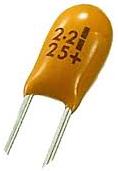
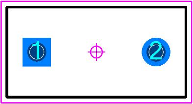
3 Polarized Radial Rectangular Leaded Component Library Expert Through-hole Families Capacitor, Polarized Radial Dipped Round Capacitor, Polarized Radial Dipped Round Capacitor, Polarized Radial Electrolytic Capacitor, Polarized Radial Electrolytic Capacitor, Polarized Radial Dipped Rectangle Capacitor Radial Dipped Rectangle LED Radial Diameter LED Radial Diameter LED Radial Rectangular LED Radial Round


 Flange")
")
4 Two Pin Crystal (XTAL) Two Pin Crystal Two Pin Crystal Four Pin Oscillator (OSC) Four Pin Oscillator Four Pin Oscillator Flange Mount Horizontal (TO-220) Flange Mount Horizontal (TO-220) Flange Mount Horizontal (TO-220)
 Library Expert")
 (TO-220)")
 Single")
")

5 Flange Mount Vertical (TO-220) Library Expert Through-hole Families Flange Mount Vertical (TO-220) Flange Mount Vertical (TO-220) Cylindrical (JEDEC TO) Cylindrical (JEDEC TO) Cylindrical (TO-99) Single In-line Package (SIP) Single In-line Package (SIP) Single In-line Package (SIP)
 (DIP) (DIP) Zero")

 Socket Zero")
")
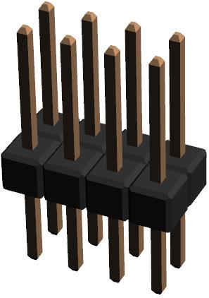
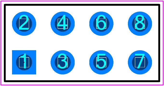
6 Dual In-Line Package (DIP) Dual In-Line Package (DIP) Dual In-Line Package (DIP) Zero Rotation Level A Dual In-Line Package (DIP) Zero Rotation Level B Dual In-Line Package Socket (DIPS) Dual In-Line Package Socket (DIPS) Dual In-Line Package Socket Zero Rotation Level A Dual In-Line Package Socket Zero Rotation Level B Header, Vertical (HDR) Header, Vertical (HDR) Header, Vertical (HDR)
 Header, Right Angle (HDRRA)")
 Zero Rotation Level A")
 Reference")

7 Header, Right Angle (HDRRA) Header, Right Angle (HDRRA) Header, Right Angle (HDRRA) Pin Grid Array (PGA) Pin Grid Array (PGA) Pin Grid Array (PGA) Zero Rotation Level A Pin Grid Array (PGA) Zero Rotation Level B Download Through-hole (PTH) Reference Calculator

8 Polarity Marking Legend The goal of the Polarity Marking Legend is to aid assembly to avoid polarized component packages from being inverted during the assembly machine setup or manual solder process. Therefore, Polarity Marking is only necessary on land patterns that require a specific rotation during the assembly process. For very dense part placements, the polarity marker can be placed under the package and covered up during the assembly process. However, the best practice is to locate the polarity indicator outside the package so that it is visible after the assembly process to allow the end user to visually validate that the assembly insertion process is correct. This is typically known as Post Assembly Inspection Process. Polarity Markings are unique from company to company. Here are samples of the most popular shapes. The size, rotation and location of the Polarity Markings are user definable. Here are some recommendations. The most popular polarity marking is a filled Dot. The size of the Polarity Marking is relevant to the size of the component package and pad width. However, the polarity dot size is also dependent on the part placement density and the assembly shops ability to easily locate the dot to avoid component rotation insertion errors. The smallest visible markings range from 0.25 mm 0.40 mm and are typically used for micro-miniature packages or very dense part placement PCB layouts. The average size ranges are 0.50 mm 0.80 mm. The largest recommended polarity dot is 1.00 mm. This illustration indicates 3 popular locations for a 0.50 mm dot on an SOP package. The preferred polarity dot placement is at the end of the pad which is the furthest distance from the component package body. This makes the post assembly inspection process easy as the component package may move up or down during assembly reflow but the dot will always be visible. The acceptable location is the pad center but this location is also a potential via site. It is advisable to keep legend ink off non-tented vias or tented via holes. The not recommended location has a higher potential of a via site and the marking could collide with other parts during the part placement process.


9 Gull Wing Terminal Lead Legend Polarity Marking Location The component body outline legend line width should be a minimum of mm. The Polarity Marking Symbol and component body legend should have a minimum 0.75 mm gap from the solder mask. The figure below illustrates the anatomy of a land pattern and feature sizes and spaces. Sample 0.50 mm Pitch SOP Legend and Polarity Marking Rules


10 Warning, check with your PCB manufacturer to verify if they can meet the dimensional requirements. Bottom only termination packages BGA, LGA, CGA, QFN, PQFN, SON, PSON and DFN The polarity marking size should match the Terminal Width. The gap between the body legend and the polarity marker should range from 0.15 mm 0.25 mm Polarized chip capacitors packages.
General Note #1 :Different kinds of IC Packages
 2012/09/01 09:08 1/9 General Note #1 :Different kinds of IC s General Note #1 :Different kinds of IC s Click to expand Image Name Description & Examples Ball Grid Array aka BGA BGA packages are used to
IPC-7351B Electronic Component Zero Orientation For CAD Library Construction
 AppNote 10831 A P P N O T E S SM IPC-7351B Electronic Zero Orientation For CAD Library Construction Copyright 2010 Mentor Graphics Corporation Trademarks that appear in Mentor Graphics product publications
Table of Contents PLCC QFP/MQFP/FQFP/CQFP LQFP/TQFP PQFP BQFP LCC/LCCC DFN QFN...61 QFN Multiple Row...
 Table of Contents Terminology Introduction... 2 Through Hole vs. Surface Mount.... 3 Through Hole Leads...3, 4 Surface Mount Leadless... 4 Surface Mount Leaded.... 5 Component Packaging...6 Identifying
PROMOTIONAL SAMPLE is not for reproduction and has LOW RESOLUTION IMAGES to make downloads quicker.
 Resistor Color Code Chart This is not for reproduction and has LOW RESOLUTION IMAGES to make downloads quicker. 2003 2215 Sanders Road Northbrook, IL 60062-6135 Telephone: 847.509.9700 FAX: 847.509.9798
Future Trends in Microelectronic Device Packaging. Ziglioli Federico
 Future Trends in Microelectronic Device Packaging Ziglioli Federico What is Packaging for a Silicon Chip? 2 A CARRIER A thermal dissipator An electrical Connection Packaging by Assy Techology 3 Technology
This IPC-DRM-18F Promotional Sample is not for reproduction and. has Low Resolution images to make download quicker. Resistor Color Code Chart
 Resistor Color Code Chart This IPC-DRM-18F is not for reproduction and has Low Resolution images to make download quicker 2001 2215 Sanders Road Northbrook, IL 60062-6135 Telephone: 847.509.9700 FAX: 847.509.9798
MonoWave(X) Construction Guide Version 1.2. June 30th, 2018
 Construction Guide Version 1.2. June 30th, 2018") MonoWave(X) Construction Guide Version 1.2 June 30th, 2018 1 of 10 Construction Construction of the MonoWave (X) is relatively straightforward and generally only requires good general soldering skills.
MonoWave(X) Construction Guide Version 1.2 June 30th, 2018 1 of 10 Construction Construction of the MonoWave (X) is relatively straightforward and generally only requires good general soldering skills.
Electronic Dice Kit MitchElectronics 2019
 Electronic Dice Kit MitchElectronics 2019 www.mitchelectronics.co.uk CONTENTS Schematic 3 How It Works 4 Materials 5 Construction 6 Important Information 7 Page 2 SCHEMATIC Page 3 SCHEMATIC EXPLANATION
MAXIMUM. Mill-Max Introduces Gull Wing SMT.070 Pitch ShrinkDIP & SIP Sockets and Headers
 MAXIMUM solutions Mill-Max Introduces Gull Wing SMT.070 Pitch ShrinkDIP & SIP Sockets and Headers Mill-Max series 117, 127, 217 & 227 shrinkdip sockets accommodate memory chips and components which have
Assembly Manual for ISDR-136-KIT
 Assembly Manual for ISDR-136-KIT ICAS Enterprises Last Updated March 21 st, 2012 This SDR receiver kit is intended for the 136kHz band. The kit utilizes DIP IC components (no SMD) so that even a beginner
General Purpose Flasher Circuit
 General Purpose Flasher Circuit By David King Background Flashing lights can be found in many locations in our neighbourhoods, from the flashing red light over a stop sign, a yellow warning light located
SURFACE MOUNT NOMENCLATURE AND PACKAGING
 SURFACE MOUNT NOMENCLATURE AND PACKAGING Tel 800-776-9888 Email info@topline.tv w w w. t o p l i n e. t v Contents Overview... 3 Flat Chip... 4 MELF Components...10 Tantalum Capacitors.... 12 Transistors
High Efficiency POL Module
 High Efficiency POL Module MPX24AD05-TU FEATURES: High Power Density Power Module 5A Maximum Load Input Voltage Range from 9.0V to 40.0V Output Voltage Range from 1.0V to 5.0V Excellent Thermal Performance
PLCC Plastic Leaded Chip Carrier
 PLCC Plastic ed Chip Carrier Plastic ed Chip Carriers (PLCC) are four-sided J ed Plastic body packages. counts range from 20 to 84. PLCC packages can be square or rectangle. Body sizes range from.35" to
Scorpion. Rework System
 Scorpion Rework System MEET THE SCORPION REWORK SYSTEM The Scorpion Advanced Package Rework System ensures both accurate component placement and custom tailored reflow profiles in one user friendly, single
Power Inductors (IP Series)
") Multi-Layer Power Inductors (IP Series) ORDERING CODE... 1 Standard External Dimensions... 2 Power Inductor for Choke (L Type)... 3 Power Inductor for DC/DC converter (S Type)... 4 Testing Condition &
Multi-Layer Power Inductors (IP Series) ORDERING CODE... 1 Standard External Dimensions... 2 Power Inductor for Choke (L Type)... 3 Power Inductor for DC/DC converter (S Type)... 4 Testing Condition &
HP420X. 5A, High Efficiency POL Module GENERAL DESCRIPTION: FEATURES: APPLICATIONS: TYPICAL APPLICATION CIRCUIT & PACKAGE SIZE:
 FEATURES: High Power Density Power Module 5A Maximum Load Input Voltage Range from 9.0V to 40.0V Output Voltage Range from 1.0V to 5.0V Excellent Thermal Performance 94% Peak Efficiency Enable Function
INDEX BY DEVICE TYPE OF REGISTERED TRANSISTOR OUTLINES (TO) TO-5 (See TO-205-AA) Axial Leads,.281 Pin Circle
 TO-5 (See TO-205-AA) Axial Leads,.281 Pin Circle") AXIAL LEADS TO-5 (See TO-205-AA) Axial Leads,.281 Pin Circle TO-8 (See TO-233-AA) TO-9 TO-12 (See TO-205-AB) Axial Leads,.100 Pin Circle TO-18 (See TO-206-AA) 4 TO-33 (See TO-205-AC) TO-39 (See TO-205-AD)
AXIAL LEADS TO-5 (See TO-205-AA) Axial Leads,.281 Pin Circle TO-8 (See TO-233-AA) TO-9 TO-12 (See TO-205-AB) Axial Leads,.100 Pin Circle TO-18 (See TO-206-AA) 4 TO-33 (See TO-205-AC) TO-39 (See TO-205-AD)
engineered to connect Full Product Line
 engineered to connect Full Product Line TEST solutions The technical data and specifications of the products shown in this catalogue are for reference only, and apply to products available at the time
Underfilling Flip Chips on Hard Disk Drive Preamp Flex Circuits and SIPs on Substrates using Jetting Technology
 Underfilling Flip Chips on Hard Disk Drive Preamp Flex Circuits and SIPs on Substrates using Jetting Technology Michael Peterson Director, Advanced Engineering Belton mjpeterson@integraonline.com Steven
Maxi and Mini DC-DC Converter Evaluation Board
 BRICK FAMILY USER GUIDE Maxi and Mini DC-DC Converter Evaluation Board Features...1 Introduction...2 Set Up + OUT, OUT...3 + S, S...3 Secondary Control (SC)...3 Primary Control (PC)...4 Parallel (PR)...4
SMD PACKAGES. Contents. 3. Packages with four or more terminals
 MANTECH ELECTRONICS Internatinal Cmpnents Distributr TEL JHB : (011) 493-9307 CAPE : (021) 535-3150 KZN : (031) 309-7692 FAX : (011) 493-9319 sales@mantech.c.za www.mantech.c.za SMD PACKAGES Cntents 1.
Conductive Polymer Aluminum Capacitors SMD (Chip), Low Impedance
, Low Impedance") Conductive Polymer Aluminum Capacitors SMD (Chip), Low Impedance FEATURES Useful life: up to 2000 h at 105 C Very low ESR and high ripple current High voltages up to 100 V AEC-Q200 qualified products on
Conductive Polymer Aluminum Capacitors SMD (Chip), Low Impedance FEATURES Useful life: up to 2000 h at 105 C Very low ESR and high ripple current High voltages up to 100 V AEC-Q200 qualified products on
Multi-Layer Power Inductors (IP_L Series)
") Multi-Layer Power Inductors (IP_L Series) For Choke Application ORDERING CODE IP 2012 2R2 M P L 9 PRODUCT CODE IP : Multilayer Power Inductor (Lead Free) DIMENSION (L X W) Code Dimension EIA 1608 1.6 x
Multi-Layer Power Inductors (IP_L Series) For Choke Application ORDERING CODE IP 2012 2R2 M P L 9 PRODUCT CODE IP : Multilayer Power Inductor (Lead Free) DIMENSION (L X W) Code Dimension EIA 1608 1.6 x
Multi-Layer Power Inductors (IP Series)
") Multi-Layer Power Inductors (IP Series) For DC/DC Converter Application ORDERING CODE IP R M P S 9 PRODUCT CODE IP : Multilayer Power Inductor (Lead Free) DIMENSION (L X W) Code Dimension EIA. x. mm. X.
Multi-Layer Power Inductors (IP Series) For DC/DC Converter Application ORDERING CODE IP R M P S 9 PRODUCT CODE IP : Multilayer Power Inductor (Lead Free) DIMENSION (L X W) Code Dimension EIA. x. mm. X.
Electronic materials and components-a component review
 Electronic materials and components-a component review Through-hole components We start our review of components by looking at those designs with leads that are intended to be soldered into through-holes
QRPGuys Digital RF Probe
 QRPGuys Digital RF Probe First, familiarize yourself with the parts and check for all the components. If a part is missing, please contact us and we will send one. This kit contains seventeen 1206 size
Surface Mount Terminal Blocks. 950-D-SMD-DS 5.00 mm (0.197 in) Spacing poles PICTURES TECHNICAL INFORMATION. page 1/5 950-D-SMD-DS
 Spacing poles PICTURES TECHNICAL INFORMATION. page 1/5 950-D-SMD-DS") page 1/5 Surface Mount Terminal Blocks 950-D-SMD-DS 5.00 mm (0.197 in) Spacing - 2-12 poles PICTURES 950-D-SMD-DS TECHNICAL INFORMATION Description 5 mm spacing, surface mount adapted terminal block for
page 1/5 Surface Mount Terminal Blocks 950-D-SMD-DS 5.00 mm (0.197 in) Spacing - 2-12 poles PICTURES 950-D-SMD-DS TECHNICAL INFORMATION Description 5 mm spacing, surface mount adapted terminal block for
Content (RF Inductors) Multi-Layer High Frequency Inductors (IQ & HI Series) Cautions... 18
 Multi-Layer High Frequency Inductors (IQ & HI Series) Cautions... 18") Content (RF Inductors) Multi-Layer High Inductors (IQ & HI Series)... 2 Ordering Code... 2 Standard External Dimensions... 3 High Q Type (IQ Series)... 4 Standard Type (HI Series)... 5 Testing Condition
Content (RF Inductors) Multi-Layer High Inductors (IQ & HI Series)... 2 Ordering Code... 2 Standard External Dimensions... 3 High Q Type (IQ Series)... 4 Standard Type (HI Series)... 5 Testing Condition
Surface Mount Terminal Blocks. 971-SLR-SMD mm (0.197 in) Spacing poles PICTURES TECHNICAL INFORMATION. page 1/5 971-SLR-SMD-1.
 Spacing poles PICTURES TECHNICAL INFORMATION. page 1/5 971-SLR-SMD-1.") page 1/5 Surface Mount Terminal Blocks 971-SLR-SMD-1.1 5.00 mm (0.197 in) Spacing - 2-12 poles PICTURES 971-SLR-SMD-1.1 TECHNICAL INFORMATION Description US Patent # 6.224.399 B1 Canadian Patent # 2,307,922
page 1/5 Surface Mount Terminal Blocks 971-SLR-SMD-1.1 5.00 mm (0.197 in) Spacing - 2-12 poles PICTURES 971-SLR-SMD-1.1 TECHNICAL INFORMATION Description US Patent # 6.224.399 B1 Canadian Patent # 2,307,922
Surface Mount Terminal Blocks. 120-M-221-SMD 5.00 mm (0.197 in) Spacing poles PICTURES TECHNICAL INFORMATION. page 1/5
 Spacing poles PICTURES TECHNICAL INFORMATION. page 1/5") page 1/5 Surface Mount Terminal Blocks 120-M-221-SMD 5.00 mm (0.197 in) Spacing - 2-24 poles PICTURES 120-M-221-SMD 120-M-221-SMD & 120-D-111 TECHNICAL INFORMATION Description US Patent # 7,207,811 B2
page 1/5 Surface Mount Terminal Blocks 120-M-221-SMD 5.00 mm (0.197 in) Spacing - 2-24 poles PICTURES 120-M-221-SMD 120-M-221-SMD & 120-D-111 TECHNICAL INFORMATION Description US Patent # 7,207,811 B2
APPLICATION NOTE. Package Considerations. Board Mounting Considerations. Littelfuse.com
 package. Compared to products in plastic molded packages, the SESD device offers a significant performance-per-boardarea advantage. The SESD package and a dimensional view of the package bottom are shown
PDR IR-E3 Evolution Series SMD/BGA Rework Stations
 PDR IR-E3 Evolution Series SMD/BGA Rework Stations PDR Focused IR Rework Stations for Ultimate Performance for SMD/BGA/uBGA/QFN/LED Rework Available in 3 models - E3S (Standard), E3G (Gold) and E3M (Micro)
Motor Driver PCB Layout Guidelines. Application Note
 AN124 Motor Driver PCB Layout Guidelines Motor Driver PCB Layout Guidelines Application Note Prepared by Pete Millett August 2017 ABSTRACT Motor driver ICs are able to deliver large amounts of current
GHz BGA Socket User Manual
 GHz BGA Socket User Manual P a g e 1 S G B. d o c, R e v. U, A J N, 1 / 5 / 2 0 1 7 GHZ BGA SOCKET USER MANUAL Table of Contents Selecting a BGA socket 3 Socket Mechanics 3 PCB Requirements 4 Backing Plate
PDR IR-E3 Evolution Series SMD/BGA Rework Stations
 PDR IR-E3 Evolution Series SMD/BGA Rework Stations PDR Focused IR Rework Stations for Ultimate Performance in SMD/BGA/uBGA Rework NOW... Three versions of our best selling product E3S Standard E3G Gold
Build Instructions and User Guide
 Build Instructions and User Guide Getting Started To build the Rock Drill 4069 you will need: Solder Wire Cutters Soldering Iron Small pliers The kit is suitable for beginners or more experienced builders
FrelTec GmbH. Wire Wound Ceramic Chip Inductors SMD
 GmbH Mathildenstr. 10A 82319 Starnberg Germany Wire Wound Ceramic Chip Inductors SMD 8/2/2017 1/15 GmbH www.freltec.com SPECIFICATION Part Number 091 02 * 101 * J * S * T05 ** _ Type Size Value Toleranc
Surface Mount Terminal Blocks. 930-D-SMD (-DS) 3.50 mm (0.138 in) Spacing poles PICTURES TECHNICAL INFORMATION. page 1/5 930-D-SMD-DS
 3.50 mm (0.138 in) Spacing poles PICTURES TECHNICAL INFORMATION. page 1/5 930-D-SMD-DS") page 1/5 Surface Mount Terminal Blocks 930-D-SMD (-DS) 3.50 mm (0.138 in) Spacing - 2-12 poles PICTURES 930-D-SMD-DS TECHNICAL INFORMATION Description The floating terminal contacts ensure total co-planar
page 1/5 Surface Mount Terminal Blocks 930-D-SMD (-DS) 3.50 mm (0.138 in) Spacing - 2-12 poles PICTURES 930-D-SMD-DS TECHNICAL INFORMATION Description The floating terminal contacts ensure total co-planar
IDC-136II-KIT 136kHz DC RX Assembly Guide
 IDC-136II-KIT 136kHz DC RX Assembly Guide ICAS Enterprises May 2 nd,2016 The IDC-136II-KIT is a 136kHz direct conversion receiver. Most of the SDR software can be used with this receiver. It is quite easy
74x Series Chip Resistor Arrays
 Features Low Cost Thick Film Technology Leadless Surface Mount Construction Concave Convex Terminations Solder Coated Nickel Barrier Pads Isolated and Bussed Circuit Configurations Improved TCR Tracking
SM361 RIG SWITCH CONSTRUCTION MANUAL
 SM361 RIG SWITCH CONSTRUCTION MANUAL Document ver 1, For software release ver 1.1 May 27, 2016 Controls the power of 12V equipment while a vehicle is in use Product Development by: SM361 RIG SWITCH OVERVIEW
Tip: 2856 LED Lighting for the Airport Express Set Date:
 Hi All, The 2856 Airport Express set was manufactured in 1983. On 09-11-1989 the locomotive was given a digital upgrade using a 6080 decoder. It has since had a digital upgrade to a high performance motor
NP276 Series (Open Top)
") Ball Grid Array (BGA, 1.27mm Pitch) Specifications Insulation Resistance: Dielectric Withstanding Voltage: Contact Resistance: Operating Temperature Range: Contact Force: Mating Cycles: Materials and Finish
Ball Grid Array (BGA, 1.27mm Pitch) Specifications Insulation Resistance: Dielectric Withstanding Voltage: Contact Resistance: Operating Temperature Range: Contact Force: Mating Cycles: Materials and Finish
Assembly Manual for New Control Board 22 June 2018
 Assembly Manual for New Control Board 22 June 2018 Parts list Arduino 1 Arduino Pre-programmed 1 Faceplate Assorted Header Pins Full Board Rev A 9 104 capacitors 1 Rotary encode with switch 1 5-volt regulator
Jet Dispensing Underfills for Stacked Die Applications
 Jet Dispensing Underfills for Stacked Die Applications Steven J. Adamson Semiconductor Packaging and Assembly Product Manager Asymtek Sadamson@asymtek.com Abstract It is not uncommon to see three to five
Temperature Coefficient of Resistance Temperature Coefficient of Resistance, Tracking Maximum Operating Voltage Insulation Resistance
 .220 Small Outline Dual-In-Line Thick Film Surface Mount Resistor Networks RoHS Compliant Electrical Standard Resistance Range, Ohms Standard Resistance Tolerance, at 25 C Operating Temperature Range Temperature
Plot No. 15, Madam Street, Kangeyanallur, Vellore , TamilNadu
 Homemade PCB Design Printed Circuit board is essential for building the circuit. The PCB is used to arrange the components and connect them with electrical contacts. Generally to prepare a PCB requires
Assembly Instructions for the KA Electronics Flat MM Phono Preamplifier
 Assembly Instructions for the KA Electronics Flat MM Phono Preamplifier Install IC sockets Flat MM Phono Preamp PC Board Stuffing Guide Place the PC Board on the bench silkscreen side face up. Drop six
APEC 2011 Special Session Polymer Film Capacitors March 2011
 This presentation covers current topics in polymer film capacitors commonly used in power systems. Polymer film capacitors are essential components in higher voltage and higher current circuits. Unlike
Semiconductor Manufacturing Technology. Semiconductor Manufacturing Technology
 Semiconductor Manufacturing Technology Michael Quirk & Julian Serda October 2001 by Prentice Hall Chapter 20 Assembly and Packaging Four Important Functions of IC Packaging 1. Protection from the environment
PDR IR-E3 EVOLUTION SERIES. PDR Focused IR Rework Stations for Ultimate Performance for SMD/BGA/uBGA/QFN/LED Rework. Trusted by Experts
 PDR IR-E3 EVOLUTION SERIES PDR Focused IR Rework Stations for Ultimate Performance for SMD/BGA/uBGA/QFN/LED Rework Trusted by Experts Multi-purpose flexible rework focused on precision and simplicity Click
7331A Garden Grove Blvd, Garden Grove, CA Tel Fax
 (R) 7331A Garden Grove Blvd, Garden Grove, CA 92841 Tel. 1-800-776-9888 Fax 1-714-891-0321 e-mail info@topline.tv www.topline.tv c 1998 TopLine. All Rights Reserved Table of Contents Definition of Dummy
THA and THAS, Thinpack, Aluminum Electrolytic Capacitors
 THA and THAS, Thinpack, Aluminum Electrolytic Capacitors Highest Energy-Density Electrolytic in a Very Low-Profile Design Welcome to the THA and THAS Thinpack Capacitor Training Module from Cornell Dubilier.
Application Note: APN-06001
 Subject: UNIVERSAL CONTACT PICK & PLACE APPLICATION Description: Application recommendations for pick and place of Universal Contact product range using production SMT equipment. SCOPE: The scope of this
Ljunggren Audio Roll Your Own Penta
 Ljunggren Audio Roll Your Own Penta Version: Penta 1.0 Bills Of Material Bold = PCB1, The rest = PCB2 Type Parts Des cription Pow er header Qty Value 1 2x5pin POWER Euro pow er connector Jack 1 3.5mm J1,
3M Assembly Equipment
 M Assembly Equipment M TM Presses and Accessories All M TM Assembly Presses are designed to provide proper assembly on M TM Cable and Connectors. These presses, along with a locator plate, achieve accurate
IV-3 VFD Shield for Arduino. Assembly Manual
 June 2014 Table of Contents 1 Overview Features Applications 3 3 3 2 Assembly Hints 4 3 PCB Overview 5 4 Circuit Diagram 6 5 Assembly Diodes and IC socket Electrolytic capacitors Ceramic capacitors 10K
Surface Mount Terminal Blocks. 971-SLR-THR 5.00 mm (0.197 in) Spacing poles PICTURES TECHNICAL INFORMATION. page 1/5 971-SLR-THR
 Spacing poles PICTURES TECHNICAL INFORMATION. page 1/5 971-SLR-THR") page 1/5 Surface Mount Terminal Blocks 971-SLR-THR 5.00 mm (0.197 in) Spacing - 2-12 poles PICTURES 971-SLR-THR TECHNICAL INFORMATION Description Standoffs underneath the molding prevent bottom of molding
page 1/5 Surface Mount Terminal Blocks 971-SLR-THR 5.00 mm (0.197 in) Spacing - 2-12 poles PICTURES 971-SLR-THR TECHNICAL INFORMATION Description Standoffs underneath the molding prevent bottom of molding
MAX16920B Evaluation Kit Evaluates: MAX16920A/MAX16920B
 19-5744; Rev 0; 1/11 MAX16920B Evaluation Kit General Description The MAX16920B evaluation kit (EV kit) is an assembled and tested PCB used to evaluate the MAX16920B powermanagement IC for automotive radios,
MTU2 Series Isolated 2W Single & Dual Output SM DC/DC Converters
 www.murata-ps.com MTU2 Series SELECTION GUIDE FEATURES Patent Protected UL 9 Recognised Footprint over pins.69cm 2 Single & dual isolated output 1kVDC Isolation Hi Pot Test Efficiency up to 85% (Typ.)
HW-8-LM386 Audio Amplifier Board Assembly Instructions
 This LM386 based audio amplifier kit was designed to replace the small audio amplifier board in the Heathkit HW-8 transciever. The result is the ability to drive regular modern day 8 ohm headphones or
Tip: - Württemberg Era 1 Open Platform Cars LED Lighting Upgrade Date: , Photos
 Hi All, As I continue my LED light conversions of my rolling stock I have just completed all the Württemberg era 1 open platform cars I have which will make up four trains with eight cars per train. These
Platinum-chip Temperature Sensors in SMD Design Type According to DIN EN 60751
 Data Sheet 906125 Page 1/5 Platinum-chip Temperature Sensors in SMD Design Type According to DIN EN 60751 Design type PCS/PCF For temperatures from -50 to +150 C (-70 to +250 C) In accordance with DIN
MTU1 Series Isolated 1W Single & Dual Output SM DC/DC Converters
 www.murata-ps.com MTU1 Series SELECTION GUIDE FEATURES Patent Protected UL60950 recognised Footprint over pins 0.69cm 2 Single & dual isolated output 1kVDC Isolation Hi Pot Test Efficiency up to 88% (Typ.)
MGV (Marshall TM Guv'nor TM Replica) Instructions
 Instructions") This is a replica of the Marshall TM Guv'nor TM Distortion referred to as MGV in these documents. Use the project documents provided, starting with the General Build Instructions. Follow the layout diagrams
This is a replica of the Marshall TM Guv'nor TM Distortion referred to as MGV in these documents. Use the project documents provided, starting with the General Build Instructions. Follow the layout diagrams
AC-DC Converter Application Guidelines
 AC-DC Converter Application Guidelines 1. Foreword The following guidelines should be carefully read prior to converter use. Improper use may result in the risk of electric shock, damaging the converter,
BOARD LEVEL RELIABILITY OF FINE PITCH FLIP CHIP BGA PACKAGES FOR AUTOMOTIVE APPLICATIONS
 As originally published in the SMTA Proceedings BOARD LEVEL RELIABILITY OF FINE PITCH FLIP CHIP BGA PACKAGES FOR AUTOMOTIVE APPLICATIONS Laurene Yip, Ace Ng Xilinx Inc. San Jose, CA, USA laurene.yip@xilinx.com
#$"&! "# % &(")# % %!!*,-
# % %!!*,-") ! "! #$% #$"&! '' "# % &(")# %!*+ %!!*,- . Flip Chip! Fine Pitch & Low-K Wire Bonding Test Program Conversion Substrate/Bumping/Assembly/Test Turnkey Solution! Stacked Die SIP BCC QFN MEMS Green Solutions!
! "! #$% #$"&! '' "# % &(")# %!*+ %!!*,- . Flip Chip! Fine Pitch & Low-K Wire Bonding Test Program Conversion Substrate/Bumping/Assembly/Test Turnkey Solution! Stacked Die SIP BCC QFN MEMS Green Solutions!
mm. Film dielectric trimmers QUICK REFERENCE DATA
 5 mm FEATURES Housing diameter 5 mm Top and bottom or top adjustment Round or hexagonal head Vertical version. APPLICATIONS For consumer and industrial equipment. DESCRIPTION The vanes of the trimmer are
Product Range BGA Rework Stations
 Product Range BGA Rework Stations PDR IR-E6 Evolution XL Ultimate Performance, BGA Rework System for Very Large PCBs Medium - large sized PCBs - SMDs, BGAs, ubgas Software controlled, Focused IR process
Tip: LED Lighting for the 4367 SBB Euro City Set, 4366 and 4368 Cars Date: , Corrections Modified , Photos
 Hi All, I have had the 4367 SBB Euro City set with extra cars 4366 and 4368 since 1998, apart from a test run on the layout they have stayed in storage ever since. I decided to change some rolling stock
System. Specifications
 Kit Part Numbering System WebCode XK1 926 Series 900 = QFP Lead Template 901 = FC176 Flip Chip 902 = FC88 Flip Chip 903 = FC317 Flip Chip 904 = FC220 Flip Chip 905 = CBGA Ceramic Substrates 906 = FC96
GT Silver Button Technology Socket for Semiconductor Test
 GT Silver Button Technology Socket for Semiconductor Test Toll Free: (800) 404-0204 U.S. Only Tel: (952) 229-8200 Fax: (952) 229-8201 email: info@ironwoodelectronics.com Application Need Prototype Test
D6, D7, D8, D9, D12, D13, D14, D15, D16, D17, D18, D19. Schottky rectifier diode. 1N5817-1N5819 or SB130
 Roll Your Own ljunggrenaudio.com Altered States version 1.0 Bills Of Material Qty Value 12 1N4148 2 1N5818 4 1N750 4.7V 4 220p Device Diode Diode Zener diode Capacitor 30 100n 4 15p 8 560p 1 5x2 pin Capacitor
Lab Electronics Reference: Tips, Techniques, and Generally Useful Information for the Labs
 ENGR 112 September 16, 14 Lab Electronics Reference: Tips, Techniques, and Generally Useful Information for the Labs This guide contains some useful reference information to help get you started on your
Fine Pitch SMT Stacking Connectors (Parallel Board-to-Board) Fine Pitch SMT Stacking Connectors (Parallel Board-to-Board) Stacking Height mm inch
 Fine Pitch SMT Stacking Connectors (Parallel Board-to-Board) Stacking Height mm inch") Fine Pitch SMT Stacking Stacking Height Guide for Parallel Board-to-Board Applications Fine Pitch SMT Stacking Stacking Height Guide for Parallel Board-to-Board Applications (Continued) Stacking Height
Fine Pitch SMT Stacking Stacking Height Guide for Parallel Board-to-Board Applications Fine Pitch SMT Stacking Stacking Height Guide for Parallel Board-to-Board Applications (Continued) Stacking Height
Contents CORNELL DUBILIER
 Contents Products Listed by Type Designation........................................................ Chip and SMT Selector Guide................................................................... 1.001
About Us. even in allocation times.
 History The company SIEGERT was founded in 1945 by Dipl.-Ing. Ludwig Siegert. During the 50ies the enterprise focused on the manufacturing of film resistors. 1965 was the start of production of miniaturized
Surface Mount Terminal Blocks. 971-SLK-THR 5.00 mm (0.197 in) Spacing poles PICTURES TECHNICAL INFORMATION APROVAL INFORMATION.
 Spacing poles PICTURES TECHNICAL INFORMATION APROVAL INFORMATION.") page 1/5 Surface Mount Terminal Blocks 971-SLK-THR 5.00 mm (0.197 in) Spacing - 2-12 poles PICTURES 971-SLK-THR 971-SLK-THR & 950-HAF-DS TECHNICAL INFORMATION Description Pinstrip Typical application Technical
page 1/5 Surface Mount Terminal Blocks 971-SLK-THR 5.00 mm (0.197 in) Spacing - 2-12 poles PICTURES 971-SLK-THR 971-SLK-THR & 950-HAF-DS TECHNICAL INFORMATION Description Pinstrip Typical application Technical
TL RELAYS. TYPICAL APPLICATIONS Head lamp, Fog lamp, Fan motor, etc. ORDERING INFORMATION TYPES. High Load Relay for Smart Junction Box ACTL.
 High Load Relay for Smart Junction Box TL RELAYS High heat-resistant type: Sealed Pin in Paste compliant type: Flux tight New 14.4.7 11.433 1.3 FEATURES Large capacity switching
Schematic VCC J1 1 CON1 +5V D26 D25 D7 D8 D9 D10 D11 D12 D19 D20 D21 D22 D23 D24 D1 D2 D3 D4 D5 D6 D13 D14 D15 D16 D17 D18 R4 100R R2 100R R6 100R
 Schematic +5V S D1 D2 D3 D4 D5 D6 D7 D8 D9 D10 D11 D12 D19 D20 D21 D22 D23 D24 D13 D14 D15 D16 D17 D18 D25 D26 R1 4K7 R2 100R Q1 9014-PNP C1 47uF R3 4K7 R4 100R Q2 9014-PNP C2 47uF R5 4K7 R6 100R Q3 9014-PNP
CAPI BB2521 Build Guide & BOM
 This is a very simple build. I only have a few tips and things to look out for. I do recommend following these steps due to the diode/transistor relationship. 1. Install the three ceramic caps. If you
MLCC(Multilayer Ceramic Capacitors) C0G Guide for Resonance Circuits
 C0G Guide for Resonance Circuits") (1/4) Vol.1 Features of High voltage MLCCs with C0G Characteristics and Replacement Solutions A wide variety of capacitors, each with their own special characteristics, are used in electronic devices.
(1/4) Vol.1 Features of High voltage MLCCs with C0G Characteristics and Replacement Solutions A wide variety of capacitors, each with their own special characteristics, are used in electronic devices.
Printed Circuit Board Fabrication And Assembly
 Printed Circuit Board Fabrication And Assembly Copyright 2004 D. L. Gould & Niagara College Niagara College -Technology Design Factors for Printed Circuit Boards Familiarization with darkroom procedures
Thermal Characterization and Modeling: a key part of the total packaging solution. Dr. Roger Emigh STATS ChipPAC Tempe, AZ
 Thermal Characterization and Modeling: a key part of the total packaging solution Dr. Roger Emigh STATS ChipPAC Tempe, AZ Outline: Introduction Semiconductor Package Thermal Behavior Heat Flow Path Stacked
LABORATORY 2 SPECIFICATION UNITS MIN MAX NOTES. Input Voltage V USB Standard. Input Current ma None
 LABORATORY 2 ASSIGNED: 2/8/18 OBJECTIVE: The purpose of this lab is to give you the opportunity of making a simple power supply circuit containing a DC-DC converter, a linear regulator and an inverting
Rockwell Collins 2019 BRS Service Parts Catalog
 000-0146-040 CAPLUG 5.80 000-0146-050 CAPLUG 7.43 000-0146-070 CAPLUG 3.02 000-0146-080 CAPLUG 2.42 009-0178-060 FAN, TUBEAXIAL 147.93 009-0271-060 FAN, TUBEAXIAL 1818.53 009-0271-070 FAN, TUBEAXIAL 2446.79
Using the HT13R90 in Simple Charger Applications
 Using the HT13R90 in Simple Charger Applications D/N: HA0148E Introduction This product is a simple Ni-MH charger, which can charge AA and AAA cell types. The charger has only a time setup function. When
NME 5V & 12V SERIES. Technical enquiries tel: +44 (0) Isolated 1W Single Output DC/DC Converters
 Isolated 1W Single Output DC/DC Converters") FEATURES RoHS compliant Single isolated output 1kVDC isolation Efficiency up to 80% Wide temperature performance at full 1 watt load, 40 C to 85 C Power density 1.53W/cm 3 UL 94V-0 package material Footprint
FEATURES RoHS compliant Single isolated output 1kVDC isolation Efficiency up to 80% Wide temperature performance at full 1 watt load, 40 C to 85 C Power density 1.53W/cm 3 UL 94V-0 package material Footprint
2.0 CONSTRUCTION 3.0 OPERATION. SA-1 Generator Differential Relay - Class 1E 2.5 TRIP CIRCUIT
 41-348.11C SA-1 Generator Differential Relay - Class 1E 2.0 CONSTRUCTION The type SA-1 relay consists of: Restraint Circuit Sensing Circuit Trip Circuit Surge Protection Circuit Operating Circuit Amplifier
MS52XX SMD Pressure Sensor
 1, and 12 bar absolute pressure range Uncompensated Piezoresistive silicon micromachined sensor Surface mount 7.6 x 7.6 mm Low-noise, high-sensitivity, high-linearity DESCRIPTION The MS52XX SMD pressure
OVERLOAD PROTECTION. All electrical circuits must have some means of protecting against overload.
 AN OVERLOAD PROTECTION CIRCUIT FOR AN INVERTER OR AN ELECTRIC FUSE FOR THE A.C. MAINS SUPPLY WITH A RESET BUTTON. PROJECT NO. 103 BY OPIYO LYDIA ACHIENG EXAMINER : PROF. M.K. MANG OLI SUPERVISOR: DR. C.
PDR BGA REWORK STATIONS. Trusted by Experts
 PDR BGA REWORK STATIONS Trusted by Experts PDR IR-E6 Evolution XL Ultimate Performance, BGA Rework System for Very Large PCBs Medium - large sized PCBs - SMDs, BGAs, ubgas Software controlled, Focused
MOTHMAN FUZZ ASSEMBLY INSTRUCTIONS RECOMMENDED TOOL AND SUPPLY LIST MOTHMAN FUZZ KIT PARTS LIST
 MOTHMAN FUZZ ASSEMBLY INSTRUCTIONS Thank you for purchasing the J201 Clean Boost Pedal Kit from Mammoth Electronics! This is a intermediate level kit that and we have made every effort to make the assembly
Total solder points: 93 Difficulty level: beginner advanced 10 LED MONO VU METER K4304 ILLUSTRATED ASSEMBLY MANUAL
 Total solder points: 93 Difficulty level: beginner 1 2 3 4 5 advanced 10 LED MONO VU METER K4304 Add a visual readout to your existing or new equipment. ILLUSTRATED ASSEMBLY MANUAL H4304IP-1 Features &
Aluminum Electrolytic Capacitors Power Ultra Long Life Snap-In
 Aluminum Electrolytic Capacitors Power Ultra Long Life Snap-In 059 PLL-SI 159 miniaturized 85 C PUL-SI Fig. 1 157 PUM-SI QUICK REFERENCE DATA DESCRIPTION VALUE Nominal case size (Ø D x L in mm) 22 x 25
Dynamis LIX Batteries
 Dynamis LIX Batteries Technical Manual LIX Batteries DYNAMIS-LIX-TecBrochure 06/2015 Page 1 of 7 Content Handling, Safety and Assembly of LIX batteries 1 General safety 2 Information for safety 3 Marking
Designing with SiC & GaN devices with Emphasis on EMC & Safety considerations
 Designing with SiC & GaN devices with Emphasis on EMC & Safety considerations Dr. Supratim Basu, Prof. Tore Undeland & Prof. Jorma Kyyrä Seminar Presentation Time: Full day Seminar Presentation Abstract:
Assembly Instructions
 Assembly Instructions for the PA3 3.1 MHz Switch Mode Plasma Tube Amplifier Kit PA3 Amplifier shown mounted on HS2 Heat Sink (The HS2 shown here is not included with this kit.) Manual v1.01 30 September