IMPORTANT SAFETY INFORMATION
|
|
|
- Clarissa Simmons
- 5 years ago
- Views:
Transcription
1 Service Manual Model BLF50 UL Part Number IMPORTANT SAFETY INFORMATION: Always read this manual first before attempting to service this fireplace. For your safety, always comply with all warnings and safety instructions contained in this manual to prevent personal injury or property damage. Dimplex North America Limited 1367 Industrial Road Cambridge ON Canada N1R 7G In keeping with our policy of continuous product development, we reserve the right to make changes without notice Dimplex North America Limited REV PCN DATE JUL JAN R01
2 TABLE OF CONTENTS OPERATION...3 EXPLODED PARTS DIAGRAM...4 WIRING DIAGRAM...5 PREPARATION FOR SERVICE...6 INSTRUCTIONS FOR REMOVING FROM WALL...7 Surface Mount... 7 Recessed Mount - Partial In-wall... 8 Flush Mount Complete In-wall... 8 LED LIGHT STRIPS REPLACEMENT...9 LED DRIVER BOARD REPLACEMENT...9 FLICKER MOTOR/FLICKER ROD REPLACEMENT...10 ELEMENT REPLACEMENT...10 HIGH TEMPERATURE CUTOUT REPLACEMENT...10 BLOWER/FAN REPLACEMENT...11 ON/OFF SWITCH REPLACEMENT...11 REMOTE SWITCHBOARD REPLACEMENT...12 REMOTE CONTROL RECEIVER REPLACEMENT...12 POWER CORD REPLACEMENT...12 ASSEMBLY PART PICTURES...14 TROUBLESHOOTING GUIDE...18 Always use a qualified technician or service agency to repair this fireplace.! NOTE: Procedures and techniques that are considered important enough to emphasize. CAUTION: Procedures and techniques which, if not carefully followed, will result in damage to the equipment. WARNING: Procedures and techniques which, if not carefully followed, will expose the user to the risk of fire, serious injury, or death. 2
.")
3 OPERATION The BLF50 operates in a 3-Stage process. These stages can be controlled either by the remote control or by the manual controls which are located on the right side of the unit and inside the air intake slot (Figure 1). Figure 1 C B A Manual Controls A. On/Off Switch The On/Off Switch supplies power to all fireplace functions. When the switch is in the -- position, the unit is on. When in the O position, the fireplace is off. B. 3-Position Selection Switch The 3-Position Selection Switch changes the mode the fireplace operates in and has three (3) positions: MANUAL ; OFF ; and REMOTE. When in REMOTE mode, the fireplace's three levels of operation are controlled by the ON and OFF buttons of the remote control. In OFF mode, power to all functions is cut off. In MANUAL mode, the fireplace's three levels of operation are controlled by the Manual Control Buttons. C. Manual Control Buttons The Manual Control Buttons operate the fireplace levels sequentially (from off): flames only; to flames and low heat; to flames and high heat. The level is increased every time the -- button is pressed, and the fireplace can be turned off at any point by pressing the O button. Resetting the Temperature Cutoff Switch Should the heater overheat, an automatic cut out will turn the fireplace off and it will not come back on without being reset. It can be reset by switching the On/Off Switch to Off and waiting five (5) minutes before switching the unit back on. CAUTION: If you need to continuously reset the heater, disconnect power and call Dimplex customer service at DIMPLEX ( ). Remote Control The fireplace is supplied with a radio frequency remote control. This remote control has a range of approximately 50 feet (15.25 m), it does not have to be pointed at the fireplace and can pass through most obstacles (including walls). It is supplied with one of hundreds of independent frequencies to prevent interference with other units.! NOTE: Before attempting any operation with the remote, pull the plastic insulator strip out from between the remote casing and battery cover (Figure 2). Remote Control Initialization/Reprogramming If the remote control or receiver board has been replaced, follow these steps to initialize the remote control and receiver: 1. Ensure that power is supplied through the main service panel. 2. Turn On/Off Switch to On (Figure 1A). 3. Move the 3-Position Selection Switch to the REMOTE position (Figure 1B). 4. Press and hold the Manual Control Button marked -- (Figure 1C) for five (5) seconds. After five (5) seconds, there is a 10 second window to press any button on the remote control. 5. Within 10 seconds press any button on the remote control. If the unit does not initialize, turn the On/Off Switch off for 30 seconds and try starting at Step 1. This will synchronize the remote control and receiver. Remote Control Usage The remote control operates the fireplace levels sequentially (from off): flames only; to flames and low heat; to flames and high heat. The level is increased every time the ON button is pressed on the remote control and the fireplace can be turned off at any point by pressing the OFF button. Battery Replacement To replace the battery: 1. Slide battery cover open on the Remote Control (Figure 2). 2. Install one (1) 12-Volt (A23) battery in the battery holder. 3. Close the battery cover Figure 2 On Button Off Button Plastic Strip Battery Cover Battery must be recycled or disposed of properly. Check with your Local Authority or Retailer for recycling advice in your area. 3
4 EXPLODED PARTS DIAGRAM Replacement Parts List 1. Element RP 2. Partially Reflective Glass RP 3. Blower/Fan RP 4. Front Glass RP 5. Power Cord RP 6. Flicker Motor RP 7. Flicker Rod RP 8. Cutout RP 9. LED Light Strips RP 10. Remote Control Receiver RP 11. Remote Switchboard RP 12. LED Driver Board RP 13. On/Off Switch RP 14. Terminal Block RP 15. Capacitor RP 16. Remote Control RP 17. Glass Ember Bed RP 18. Hardware Kit RP 19. Plastic Media Tray RP 20. Front Glass Mounting Hardware RP OEM Accessory River Rocks...DFS
5 WIRING DIAGRAM üüü LED DISPLAY BOARD ELEMENT üüü LED DRIVER BOARD SWITCH BOARD CAPACITOR TERMINAL BLOCK FLICKER MOTOR 3-STAGE RECEIVER BOARD- LINEAR WIRE NUT CORD SWITCH- ON/OFF WIRE NUT 5
6 PREPARATION FOR SERVICE! NOTE: All components are replaceable from the front of the fireplace while the unit is mounted on the wall, with the exception of replacement of the power cord.! NOTE: If the power cord needs replacing or if the unit needs to be removed from the wall for any other reason please begin service by following the PREPARATION FOR SERVICE instructions, then move on to the section INSTRUCTIONS FOR REMOVING FROM WALL. Tools Required: Philips head screwdriver 1. Disconnect power source. Unplug the fireplace from the outlet. If unit has been hardwired for power or outlet is not accessible from the front, turn the breaker off at the electrical panel. 2. Remove the front glass assembly by removing the 2 screws (1 on the left and 1 on the right side, located just inside the top front vent opening). These screws secure the front glass panel to the inside of the fireplace. (Figure 4) 3. Lift the front glass assembly off of the 4 mounts located between the outer and inner casing of the fireplace: 2 on the left and 2 on the right. (Figure 3) Carefully place the glass assembly aside in a safe location. 4. Remove the decorative glass ember-bed pieces from the media tray, which lies along the bottom of the interior Partially Reflective Glass. A medium sized container such as a bucket or a box will be needed to keep the glass ember-bed pieces together.! NOTE: Try to ensure the pieces do not get pushed or wedged underneath the Partially Reflective Glass. They may obstruct the ease of removing the Partially Reflective Glass from the fireplace. 5. Remove the Partially Reflective Glass by removing the 2 screws on each bracket; (2-brackets in total), located on the left and right side of the Partially Reflective Glass. 6. With one hand gently supporting the Partially Reflective Glass, carefully pry the Partially Reflective Glass forward from the upper half so that it begins to tilt forward from the top. Grasp the Partially Reflective Glass from the sides and carefully lift it up and out from the front of the fireplace. Set it aside in a safe place. 7. Remove the plastic media tray by removing the 6 screws: 3 on the left and 3 on the right of the tray. (Figure 5) 8. The tray has a small lip that goes underneath and slightly up behind the Partially Reflective Glass - from Figure 3 Figure 4 Figure 5 Front Panel Tab Mounts (4) Hooks (4) Front Panel tabs (2) Media Tray screws (6) the front edge, pull the tray up and forward to take it out of the fireplace. CAUTION: Partially Reflective Glass is not tempered. Do not bump or drop the Partially Reflective Glass to avoid breakage and personal injury.! NOTE: Once the repair is completed, replace the media tray first before re-inserting the Partially Reflective Glass. Re-place 1 screw on both the left and right side of the media tray closest to the front to align the tray and keep it in place. Put the Partially Reflective Glass with the rubber protective strip at the top and secure with the side mounting brackets Secure the remaining 4 screws in the media tray. 6
7 Figure " (123 cm) 46" (116 cm) 3" (7.6 cm) " (128 cm) 7" (17.8 cm) (49.5 cm) 16" (40.6 cm) 18" (45.7 cm) 9. Proceed to the instructions within this manual relating to the repair being performed - see Table of Contents for page number. INSTRUCTIONS FOR REMOVING FROM WALL! NOTE: Only required for replacement of the power cord or removal from service. Mounting - The fireplace may be mounted in one of 3 methods: Surface Mount Recess Mount (partially in the wall) Flush Mount (completely in the wall) Identify the type of mounting and follow the appropriate instructions in the following pages. (See Figure 6 for the top and side profile view with measurements of the back panel). CAUTION: Two people will be required for removal and re-installation of the fireplace. The unit is approx. 50 5/16 w x 19 1/2 h x 7 d. Weight is approximately 75lbs. CAUTION: To prevent injury or damage, turn off the breaker in your electrical panel prior to attempting to remove this unit off the wall.! NOTE: If fireplace is hard wired directly to the electrical panel, and there is not enough slack in the wires within the wall to reach your work area, remove the electrical junction box cover located on the bottom right by removing the 1 screw on the front of the cover. Lift the cover off and set aside. Disconnect the 3 wire connectors connected to the " (9.7 cm) power source, taking note of their original configuration. Surface Mount (Figure 7) Tools Required: Philips head screwdriver 1. Partially unscrew the rear mounting screws that are holding the fireplace to the wall along the back panel of the unit. Support the weight of the fireplace when loosening the screws so unit does not fall off the wall unexpectedly.! NOTE: Be sure to take note of which keyhole mount openings were used for positioning the fireplace so that it can be re-placed in the same location when service is complete. (Figure 7) 2. Take the fireplace off the wall by carefully lifting the fireplace off the mounting screws so they line up to the larger part of the keyhole openings and pull forward. Carefully lay the unit down on a solid flat surface with the front of the unit facing up. Figure 7 Key-hole Wall stud Permanent mounting hole 7
8 ! NOTE: If the surface you are using as a work area on is a finished surface that is prone to scratches (i.e. hardwood flooring), it is recommended that a protective barrier be used underneath, (i.e. cloth, cardboard, thick plastic). 3. Proceed to the instructions within this manual relating to the repair being performed - see Table of Contents for page number. 4. Once repair is complete, reassemble in the reverse order as above. Recessed Mount - Partial In-wall (Figure 8) Tools Required: Philips head screwdriver 1. Remove the 4 mounting screws located approximately 3 inches deep in the space between the outer and inner casing on the left and right hand side. There are 2 screws per side, upper and lower going into a stud. (Figure 9) CAUTION: The fireplace should be supported while removing the screws to prevent the unit from falling. 2. Remove the fireplace out of the opening by slightly lifting and pulling forward. 3. Carefully lay the unit down on a solid flat surface with Figure 8 the front of the unit facing up.! NOTE: If the surface you are using as a work area is a finished surface that is prone to scratches (i.e. hardwood flooring), it is recommended that a protective barrier be used underneath, (i.e. cloth, cardboard, thick plastic). 4. Proceed to the instructions within this manual relating to the repair being performed - see Table of Contents for page number. 5. Once repair is complete, reassemble in the reverse order as above. Flush Mount Complete In-wall (Figure 10) Tools Required: Philips head screwdriver 1. Locate and remove the 4 mounting screws inside the unit located on left and right side towards the front. There are 2 screws per side, going from the side panels out into the side of the wall stud that frames the fireplace. (Figure 10) CAUTION: The unit should be supported while removing the screws to prevent the unit from falling. 2. Remove the fireplace out of the opening by slightly lifting and pulling forward. 3. Carefully lay the unit down on a solid flat surface with the front of the unit facing up.! NOTE: If the surface you are using as a work area is a finished surface that is prone to scratches (i.e. hardwood flooring), it is recommended that a protective barrier be used underneath, (i.e. cloth, cardboard, thick plastic). 4. Proceed to the instructions within this manual relating Figure 10 Mounting Holes Wall Surface Figure 9 Mounting Holes Mounting Hole 8
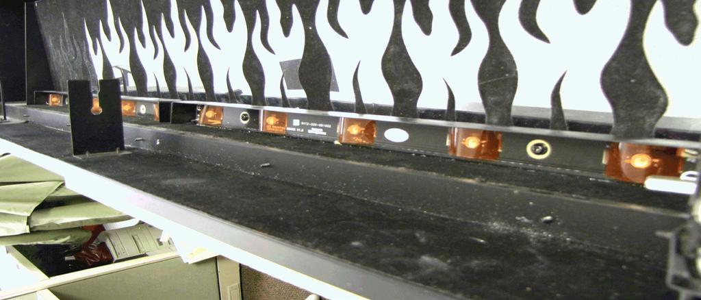
9 to the repair being performed - see Table of Contents for page number. 5. Once repair is complete, reassemble in the reverse order as above. LED LIGHT STRIPS REPLACEMENT Tools required: Phillips head screwdriver Wire snips 1. Partially release the lower face panel, by removing the screw on the left side and on the right side of the panel, inside the unit. Pull the front panel forward from the topside by approximately 2 inches. There are 3 additional screws located underneath the front face but do not need to be removed. There should be enough give to allow the panel to pull slightly forward.! NOTE: If the 3 bottom screws to the front panel are accessible in your application, you can remove them to obtain the most clearance for the repair. If they are not accessible, you can still proceed with them attached. 2. Remove the electrical junction box cover located on the bottom right hand side by removing the screw on the front of the cover. Lift the cover out and set aside. 3. Remove the flicker rod by slightly bending the rod and pulling the rubber bushing off the motor arm located on the bottom right. Remove the middle plastic bushing by lifting it up off the center bracket. Slide the remainder of the flicker rod off the end bracket on the left. CAUTION: When removing and replacing the flicker motor try to keep any slight bending of the flicker rod minimal so as to not damage it. If flicker rod is damaged, it should be replaced to ensure proper operation. 4. On the top right side, just below the Remote Switchboard, remove the 2 screws that secure the upper control panel cover. Remove the cover and set aside to allow access to the LED Driver Board wires. 5. On the LED Driver Board (smaller board on the right), remove the two (2) orange wire connectors and separate the wires - noting original configuration. 6. In the lower area of the fireplace, remove the 2 screws on each LED light strip, which secure the strips to the light strip covers. 7. Cut and remove plastic cable ties that hold the wires in place from the LED light cover at the bottom and up to the LED Driver Board at the top. 8. Gently pull the LED light strip wires up and around from the side of the light covers to free the strips. The covers may require a small amount of pressure upward, to allow a little give when feeding the wires around the covers. 9. Lift and remove LED strips out of the light covers and slide the wires out of the protective insulation. 10. Feed the wires from the new LED strip back through the same protective insulation up to the LED Driver Board. 11. Attach the new LED strips to the LED cover with the screws from step Route wires around the light covers and re-attach the covers with the screws from the outer bottom panel of the fireplace. 13. Reconnect the wires at the LED Driver Board at the top using the 2 orange wire connectors from STEP Route wires back into control panel area. 15. Reassemble in the reverse order as above. LED DRIVER BOARD REPLACEMENT Tools required: Phillips head screwdriver Needle nosed pliers Wire snips 1. On the top right side, just below the Remote Switchboard, remove the 2 screws that secure the upper control panel cover. Remove the cover and set aside to allow access to the LED Driver Board wires. 2. Remove the two (2) cable ties on the right to allow access to the wires of the LED Driver Board. 3. On the LED Driver Board (smaller board on the right), remove the two (2) orange wire connectors and separate the wires - noting their original configuration. 4. Also on the LED Driver Board remove the 2 wire connectors that join the 2 white wires together and the two black wires together. 5. To remove the Driver Board off the plastic mounts, pinch the plastic mounting tabs with needle nose pliers. Pull the old board off. 6. Connect the firebox wires onto the new LED Driver Board. Spread the flange on the top of the plastic mounting tabs apart and re-use them to re-secure the new Driver Board into the fireplace. Line up the holes on the Driver Board and gently press the new board onto the mounts. Make sure the Driver Board is secure. 7. Reassemble in the reverse order as above. 9
10 FLICKER MOTOR/FLICKER ROD REPLACEMENT Tools required: Phillips head screwdriver. 1. Partially release the lower face panel, by removing the screw on the left side and on the right side of the panel, inside the unit. Pull the front panel forward from the topside by approximately 2 inches. There are 3 additional screws located underneath the front face but do not need to be removed. There should be enough give to allow the panel to pull slightly forward.! NOTE: If the 3 bottom screws to the front panel are accessible in your application, you can remove them to obtain the most clearance for the repair. If they are not accessible, you can still proceed with them attached. 2. Remove the electrical junction box cover located on the bottom right hand side by removing the screw on the small mounting-flange on the front face of the junction box cover. Lift the cover out and set aside. Once the cover is removed, the flicker motor and terminal block will now be visible. 3. Remove the flicker motor wires from the terminal block by removing the 3 small Philips screws holding each wire in place then gently pulling the wires out of the terminal block - noting their original locations. 4. Remove the 2 screws holding the flicker motor to the mounting bracket. Gently pull the motor away from the flicker rod. CAUTION: When removing and replacing the flicker motor try to keep any slight bending of the flicker rod minimal so as to not damage it. If flicker rod is damaged, it should be replaced to ensure proper operation. 5. Properly orient the new flicker motor onto the motor bracket and re-attach with the 2 mounting screws. 6. Reassemble in the reverse order as above. ELEMENT REPLACEMENT Tools required: Phillips head screwdriver. Needle nosed pliers. Wire Snips 3/8 ratchet or wrench 1. Remove the 4 screws that secure the angled switch housing cover located just below the Remote Switchboard on the top right. Remove cover and set aside. 2. Remove the front panel that spans across the top front facia. To do so, locate the 4 screws: 2 on the left and 2 right on the angled part behind the facia. Wires from the switch housing are connected to this piece so carefully move it farther down in the body of the unit, to give some room to access the heating assembly cover. 3. Remove the heating assembly cover in the top center by removing the 10 screws on the side brackets: 5 on the left and 5 on the right. Wires from the switch housing are connected to this piece, so carefully move it farther down in the body of the unit, to give some room to access the heating assembly housing. 4. Release the top panel of the heating assembly housing by removing 4 screws on the side brackets. Pull the top panel of the heating assembly housing out from between the brackets. 5. From the top panel of the heating assembly housing, remove the 4 screws that hold the element cover to the housing panel. 6. Disconnect wires from the ends of the elements noting their original locations.! NOTE: Using a flat head screwdriver gently pry between the end of the connectors and the element to release the wires.! NOTE: Some of the wires may have a piggy-back connector that allows a second wire to connect to the same prong as the first wire. Try and keep the piggy-back connection together when pulling the wires off the element. 7. Using a 3/8 ratchet or wrench remove the hex head screw from both sides of the element. Remove elements from the element housing and replace with the new elements. 8. Reassemble in the reverse order as above. CAUTION: When re-installing covers and panels, be sure the wires are guided and tucked into the proper openings along the right side so they are not pinched and allows enough space to reinstall panel. HIGH TEMPERATURE CUTOUT REPLACEMENT Tools required: Phillips head screwdriver Needle nosed pliers Wire Snips 10
11 1. Remove the 4 screws that secure the angled switch housing cover located just below the Remote Switchboard on the top right. Remove cover and set aside. 2. Remove the front panel that spans across the top front facia. To do so, locate the 4 screws: 2 on the left and 2 right on the angled part behind the facia. Wires from the switch housing are connected to this piece so carefully move it farther down in the body of the unit, to give some room to access the heating assembly cover. 3. Remove the heating assembly cover in the top center by removing the 10 screws on the side brackets: 5 on the left and 5 on the right. Wires from the switch housing are connected to this piece, so carefully move it farther down in the body of the unit, to give some room to access the heating assembly housing. 4. Release the top panel of the heating assembly housing by removing 4 screws on the side brackets. Pull the top panel of the heating assembly housing out from between the brackets. 5. Locate the high temperature cutout and remove the mounting screw. 6. Disconnect the wiring connections noting their original locations.! NOTE: Using a flat head screwdriver gently pry between the end of the connectors and the cutout to release the wires. 7. Cut and remove plastic cable tie that hold the wires in place on the top of the panel. 8. Properly orient the new high temperature cutout and connect all of the wiring connections. 9. Reassemble in the reverse order as above. BLOWER/FAN REPLACEMENT Tools required: Phillips head screwdriver. Needle nosed pliers. 1. Remove the 4 screws that secure the angled switch housing cover located just below the Remote Switchboard on the top right. Remove cover and set aside. 2. Remove the front panel that spans across the top front facia. To do so, locate the 4 screws: 2 on the left and 2 right on the angled part behind the facia. Wires from the switch housing are connected to this piece so carefully move it farther down in the body of the unit, to give some room to access the heating assembly cover. 3. Remove the heating assembly cover in the top center by removing the 10 screws on the side brackets: 5 on the left and 5 on the right. Wires from the switch housing are connected to this piece, so carefully move it farther down in the body of the unit, to give some room to access the heating assembly housing. 4. Release the top panel of the heating assembly housing by removing 4 screws on the side brackets. Pull the top panel of the heating assembly housing out from between the brackets. 5. From the top panel of the heating assembly housing, locate and remove the 6 screws that hold the blower/ fan assembly to the housing panel. Separate the blower assembly from the housing panel. CAUTION: When removing the blower assembly mounting screws support the assembly to prevent any damage to the unit. 6. Disconnect the wiring connections noting their original locations.! NOTE: Using a flat head screwdriver gently pry between the end of the connectors and the blower/fan to release the wires. 7. Properly orient the new blower/fan assembly and connect all of the wiring connections. 8. Reassemble in the reverse order as above. ON/OFF SWITCH REPLACEMENT Tools required: Phillips head screwdriver. Needle nosed pliers. 1. Remove the 4 screws that secure the angled switch housing cover located just below the Remote Switchboard on the top right. Remove cover and set aside. 2. Remove the front panel that spans across the top front facia. To do so, locate the 4 screws: 2 on the left and 2 right on the angled part behind the facia. Wires from the switch housing are connected to this piece so carefully rotate it up 180 degrees and move it farther down in the body of the unit, to give some room for access. This will make the switch visible from behind. 3. Disconnect the wiring connections noting their original locations.! NOTE: Using a flat head screwdriver gently pry between the end of the connectors and the switch to release the wires. 4. Using needle nose pliers, pinch the tabs on either side of the switch to release and push the switch forward out of the front of the panel. 11
12 ! NOTE: Note the orientation of the switch prior to removing. 5. From the front of the panel, insert new switch by pushing switch back through the hole past the side tabs on the switch, securing it in the opening. 6. Reconnect wires onto the prongs at the back of the switch in their original configuration. 7. Reassemble in the reverse order as above. REMOTE SWITCHBOARD REPLACEMENT Tools required: Phillips head screwdriver. Needle nosed pliers Wire snips 1. Remove the 4 screws that secure the angled switch housing cover located just below the Remote Switchboard on the top right. Remove cover and set aside. 2. Remove the front panel that spans across the top front facia. To do so, locate the 4 screws: 2 on the left and 2 right on the angled part behind the facia. Wires from the switch housing are connected to this piece so carefully rotate it up 180 degrees and move it farther down in the body of the unit, to give some room for access. This will make the switch visible from behind. 3. Disconnect the wiring connections noting their original locations.! NOTE: Using a flat head screwdriver gently pry between the end of the connectors and the switchboard to release the wires. 4. To remove the switchboard off the plastic mounts, cut or pinch the plastic mounting tabs with snips or needle nose pliers. Pull the old board off. 5. Push the old mounts out towards the front/top of the facia panel. Insert and push the new mounts all the way through into the same opening. Line up the holes on the switchboard and gently press the new board onto the mounts. Make sure the board is secure. 6. Reconnect the wires onto the back of the switchboard in its original configuration.. 7. Reassemble in the reverse order as above. REMOTE CONTROL RECEIVER REPLACEMENT Tools required: Phillips head screwdriver. Needle nosed pliers. Wire snips 1. On the top right side of the back panel, just below the manual control switches, remove the 2 screws that secure the upper control panel cover. Remove the cover and set aside to allow access to the Remote Control Receiver wires (the board is the larger circuit board on the left). 2. Remove any plastic cable ties to allow for easier removal of the wires on the Remote Control Receiver. 3. Remove the wires off the Remote Control Receiver, taking careful note of the original location of the wires.! NOTE: Using a flat head screwdriver gently pry between the end of the connectors and the receiver to release the wires.! NOTE: Some of the wires may have a piggy-back connector that allows a second wire to connect to the same prong as the first wire. Try and keep the piggy-back connection together when pulling the wires off the Remote Control Receiver. 4. To remove the Remote Control Receiver off the plastic mounts, pinch the plastic mounting tabs with needle nose pliers. Pull the old board off. 5. Attach the firebox wires onto the new Remote Control Receiver. Spread the flange on the top of the plastic mounting tabs apart and re-use them to re-secure the new Remote Control Receiver into the firebox. Line up the holes on the Remote Control Receiver and gently press the new Remote Control Receiver onto the mounts - making sure the board is secure. 6. Reassemble in the reverse order as above. POWER CORD REPLACEMENT Tools required: Phillips head screwdriver. Needle nosed pliers. CAUTION: Follow Instructions from Removing from Wall 1. Partially release the lower face panel. There are 5 screws in total are holding the panel: 1 screw on the left and 1 on the right, inside the unit. There are 3 ad- 12
13 ditional screws located underneath the front face but do not need to be removed. 2. If the 3 bottom screws to the front panel are accessible in your application, you can remove them to obtain the most clearance for the repair. If they are not accessible, you can still proceed with them attached and pulling the front panel forward from the top end by approximately 2 inches. 3. Remove the electrical junction box cover located on the bottom right hand side. Lift the cover out and set aside. 4. Remove power cord junction box by removing the 3 screws located on the, bottom left corner of the firebox: 2 screws are on the outer bottom panel and 1 screw is on the outer back panel. 5. Unscrew the 2 wire connectors that join the power cord at the bottom to the wire leads coming down from the top. 6. With a pair of needle nose pliers, open the strain relief bushing that holds the power cord in place on the junction box and remove the cord. 7. Feed the new power cord through the junction box and squeeze the new strain relief in place on the cord and junction box. Re-connect wires. (Wide blade on the plug is the neutral side of the power cord). 8. Reassemble in the reverse order as above. 13


14 ASSEMBLY PART PICTURES 3-STAGE REMOTE CONTROL RECEIVER LED DRIVER BOARD MANUAL CONTROLS - Outside View REMOTE SWITCHBOARD - Inside View 14


15 LOWER ELECTRICAL HOUSING With Housing-Cover and Flicker Rod in place LOWER ELECTRICAL HOUSING With Housing-Cover and Flicker Rod Removed LED LIGHT STRIPS 15


16 LED LIGHT STRIP WIRE HARNESS HEATING ASSEMBLY ELEMENT CONNECTIONS Left and Right Side 16


17 HIGH TEMPERATURE CUTOUT Below Element Housing BLOWER MOTOR CONNECTIONS Below Element Housing 17
18 TROUBLESHOOTING GUIDE PROBLEM CAUSE SOLUTION General Circuit breaker trips or fuse Short in unit wiring. Trace wiring in unit. blows when unit is turned on Improper circuit current rating Additional appliances may exceed the current rating of the circuit breaker or fuse. Plug unit into another outlet or install unit on a dedicated 15 amp circuit. Unit turns on or off by itself Remote Control has a similar frequency to other remotes in the area. Replace Remote Control. Initialize to Remote Control Receiver. Radio frequency disturbance from outside sources. Replace Remote Control and Remote Control Receiver where necessary. Initialize Remote Control and Receiver. Defective Remote Control Receiver Replace Remote Control Receiver. Initialize Remote Control and Receiver. Lights dim in room while the unit is on Unit is drawing close to circuit current rating Move the unit to another outlet or install unit on a dedicated 15 amp circuit Power cord gets warm Normal Operation The power cord may get slightly warm to the touch when the heater is on Defective power cord Replace power cord if cord gets too hot to touch. Appearance Fireplace does not turn on Manually Improper operation Refer to Operation Section No incoming power from the electrical Check fuse/breaker panel wall socket Loose wiring Check wiring connections Defective On/Off Switch Replace On/Off Switch Defective Remote Switchboard Replace Remote Switchboard Fireplace does not turn on using Improper operation Refer to Operation Section the Remote Control Remote Control not initialized to fireplace Initialize the Remote Control Remote Control not working Install new battery into the Remote Control. Initialize Remote Control where necessary Replace Remote Control Receiver or Remote Control where necessary. Initialize Remover Control and Remote Control Receiver Flame Frozen Loose wiring. Check wiring connections Defective Flicker Motor Replace Flicker Motor Defective LED Driver Board Replace LED Driver Board Flame not bright or flame not Loose wiring Check wiring connections visible Defective LED Light Strip Replace LED Light Strip Flame Shutter Defective Flicker motor Replace Flicker motor 18
19 PROBLEM CAUSE SOLUTION Heater Heater is not turning off Improper operation Refer to Operation Section Defective Remote Switchboard Replace Remote Switchboard Defective Remote Control Receiver Replace Remote Control Receiver Heater is not turning on Improper operation Refer to Operation Section Loose wiring Trace wiring in unit. Defective Remote Switchboard Replace Remote Switchboard Defective Heating Element Replace Heating Element Heater is turning off after a couple of minutes of operation Build up of dirt/dust in Blower/Fan Ensure that exterior intake louvers and firebox cavity are free of dirt/dust. Defective Blower/Fan Replace Blower/Fan Heater emits an odor Normal Operation Normal operation is when the heater emits an odor for a brief period after the heater is initially turned on. The heater is burning off any dust accumulated during manufacturing or operation. Defective Heating Element Replace Heating Element Heater fan turns on but heater Improper operation Refer to Operation Section lacks heat Loose wiring Trace wiring in unit Defective Heating Element Replace Heating Element Heating element is glowing red Normal Operation Small glowing sections of the element are considered normal. Defective Blower/Fan If larger glowing sections are causing the heater to trip the thermal cutout, unplug unit, discontinue use and replace Blower/Fan. Heater fan runs continuously Loose wiring Trace wiring in unit Defective Remote Switchboard Replace Remote Switchboard Defective Blower/Fan Replace Blower/Fan Noise Excessive noise with the heater on Grinding or excessive noise with the heater off Dirty Blower/Fan Defective Blower/Fan Flicker rod hitting or rubbing against internal components Defective Flicker motor Ensure that exterior intake louvers and firebox cavity are free of dirt/dust. Replace Blower/Fan Ensure rod is straight and mounted properly in the bracket, spinning freely away from other components. Replace if necessary. Replace Flicker motor 19
Service Manual. Model Number: DF2426GB DF2426SS DF2550 DF2562. UL Part Number to 500
 Service Manual Model Number: DF2426GB DF2426SS DF2550 DF2562 UL Part Number 6905050100 to 500 IMPORTANT SAFETY INFORMATION: Always read this manual first before attempting to service this fireplace. For
Service Manual. Model Number UL Part Number BF33STP BF33DXP BF39STP BF39DXP BF45DXP
 Service Manual Model Number UL Part Number BF33STP 6901811400 BF33DXP 6901811500 BF39STP 6901811600 BF39DXP 6901811700 BF45DXP 6901811900 DXP Model Shown IMPORTANT SAFETY INFORMATION: Always read this
Service Manual. Model VF2927L VFA2927 VF5452L UL Part Number
 Service Manual Model VF2927L VFA2927 VF5452L UL Part Number 6909410210 6909410110 6909680110 IMPORTANT SAFETY INFORMATION: Always read this manual first before attempting to service this fireplace. For
Service Manual Mozart Fireplace
 Service Manual Mozart Fireplace Model Numbers: CFP3913 REV PCN DATE 00 11637 Sep 23, 09 Dimplex North America Limited 1367 Industrial Road Cambridge ON Canada N1R 7G8 1-888-346-7539 www.dimplex.com In
PARTS AND SERVICE MANUAL
 PARTS AND SERVICE MANUAL FOR THE 23 INSERT FIREPLACE MODEL NUMBER: DFI2309 TABLE OF CONTENTS OPERATION PAGE 1 PARTS DRAWING PAGE 3 PARTS LIST PAGE 4 WIRING DIAGRAM PAGE 5 LIGHT BULB REPLACEMENT PAGE 6
Service Manual CDFI1000P CDFI500P
 Service Manual Model Part Number CDFI1000P 6909660100 CDFI500P 6909660200 IMPORTANT SAFETY INFORMATION: Always read this manual first before attempting to service this cassette. For your safety, always
Carousel Unit User Manual Replacing the Check Stand Motor
 Carousel Unit User Manual Replacing the Check Stand Motor 02/01/2017 1 Table of Contents Tools:... 3 Turn Off Power to the Unit:... 4 Remove Power Switch... 5 Remove Electric Eyes:... 6 Remove POS (Point-Of-Sale)
IMPORTANT SAFETY INFORMATION:
 Owner s Manual Model WRCPF-KIT IMPORTANT SAFETY INFORMATION: Always read this manual first before attempting to install or use this device. For your safety, always comply with all warnings and safety instructions
IMPORTANT SAFETY INFORMATION:
 Owner s Manual Model WRCPF-KIT IMPORTANT SAFETY INFORMATION: Always read this manual first before attempting to install or use this device. For your safety, always comply with all warnings and safety instructions
CHROME ALLEY CAT L.E.D. FUEL & BATTERY GAUGE 7381
 CHROME ALLEY CAT L.E.D. FUEL & BATTERY GAUGE 7381 Thank You For Choosing Küryakyn! Protect yourself and others from potential injury and property damage or loss. Pay close attention to all instructions,
Installation Manual TWM Performance Short Shifter Cobalt SS/SC, SS/TC, HHR SS, Ion Redline and Saab 9-3
 Page 1 Installation Manual TWM Performance Short Shifter Cobalt SS/SC, SS/TC, HHR SS, Ion Redline and Saab 9-3 Please Note: It is preferable to park on a flat surface, as you will have to engage and disengage
Section 5: Parts Replacement
 Section 5: Parts Replacement Should the STAR TRAC 4500 Treadmill experience a problem requiring replacement of a specific part, the following procedures will help and instruct in the replacement of major
Installation Instructions COMPETITION/PLUS SHIFTER Ford Mustang MT82 6-Speed Manual Transmission Catalog#
 Installation Instructions COMPETITION/PLUS SHIFTER 2015-2017 Ford Mustang MT82 6-Speed Manual Transmission Catalog# 3916037 Rev. 00 WORK SAFELY! For maximum safety, perform this installation on a clean,
MAZDASPEED3 Intercooler Instructions
 MAZDASPEED3 Intercooler Instructions Congratulations on your purchase of the COBB Tuning Front Mount Intercooler System for your 2007-2009 Mazdaspeed3. The following instructions should assist you through
THIS GUIDE IS INTENDED FOR DEALERS AND SOLAR COMFORT TECHNICIANS ONLY AND IS NOT MEANT OR INTENDED TO BE REPRODUCED OR DISTRIBUTED TO THE CONSUMER
 THIS GUIDE IS INTENDED FOR DEALERS AND SOLAR COMFORT TECHNICIANS ONLY AND IS NOT MEANT OR INTENDED TO BE REPRODUCED OR DISTRIBUTED TO THE CONSUMER Table of Contents Page Tools Needed (A) 3 Replacement
SERVICE MANUAL Model: SF-INS30-BK - Instructions -
 SERVICE MANUAL Model: SF-INS30-BK - Instructions - NOTICE! DO NOT discard any hardware while servicing. It must be reused. This manual will assist a qualified service technician in the replacement of parts.
Replacing the Battery in the Patriot SPS 250, SPS 300 and SPS 450
 Replacing the Battery in the Patriot SPS 250, SPS 300 and SPS 450 PAT 609 P February 1, 1993 This PAT describes how to replace the battery in Patriot SPS 250, SPS 300, and SPS 450 units. Replacing the
GoCartVac Service Manual
 GoCartVac Service Manual Table of Contents ATTENTION Before servicing any part or proceeding with any repair procedure on any ProTeam vacuum, ALWAYS disconnect the vacuum from the power source. Battery
Replacing the Gear Drive Motor Assembly and GFCI Module for Operation with the Chain Drive Motor Assembly
 Replacing the Gear Drive Motor Assembly and GFCI Module for Operation with the Chain Drive Motor Assembly Kit Contents B00009035-3 Motor Drive Assembly (Return original to CMI) B00007698-8 GFCI Module
The POWER. In PRESENTATION PRODUCTS. Instruction Book for BOARDROOM ELECTROL DA-LITE SCREEN COMPANY, INC.
 The POWER In PRESENTATION PRODUCTS Instruction Book for BOARDROOM ELECTROL DA-LITE SCREEN COMPANY, INC. 3100 North Detroit Street Post Office Box 137 Warsaw, Indiana 46581-0137 Phone: 574-267-8101 800-622-3737
Make sure all wiring is inserted into the cavity between the insert and the fireplace. Failure to do this may cause the wiring to become damaged.
 Installation Notes Large Flush Wood Hybrid-Fyre Insert: (96400539, 96400539A) Before installing, make sure to install the one-piece panel, and disconnect the power cords making sure the Molex connector
Ford Mustang V6 OEM-Style Fog Light Kit Parts List: Quantity: Tool List:
 2015-2017 Ford Mustang V6 OEM-Style Fog Light Kit Parts List: Quantity: Tool List: LED Foglights/ Bezels 2 Flat head & Phillips screwdriver (if you ordered part#3600) Ratchet & Socket set OR Wiring harness
Conflicts: Vehicles without a sunroof Vehicles with a single sunroof
 Toyota Sienna (Dual Sunroof) 2011-10.2 Overhead Video Part Number: 00016-00110 00016-00110-17 Fit Kit 00016-00120 00016-00120-17 Fit Kit Accessory Code: ED5 Conflicts: Vehicles without a sunroof Vehicles
Replacing the Batteries in the Fortress LI 660
 Replacing the Batteries in the Fortress LI 660 This FTS describes how to replace the batteries in Fortress LI 660 units. Batteries should be replaced by a qualified technician. If you have any questions
PHOENIX MINI-GUARDIAN
 PHOENIX MINI-GUARDIAN H. E. P. A. SYSTEM Therma-Stor Products A Division of DEC International Box 8050 Madison, WI 53708 Toll Free 1-800-533-7533 Local 1-608-222-5301 Table of Contents PHOENIX MINI-GUARDIAN
Mishimoto Performance Aluminum Radiator w/ Stabilizer - Manual (97-04 GT, Mach 1; Cobra)
") Mishimoto Performance Aluminum Radiator w/ Stabilizer - Manual (97-04 GT, Mach 1; 97-01 Cobra) Installed on: 2000 Mustang GT (manual transmission) Tools: 8mm socket 10mm socket 13mm socket 3/4" wrench
Mishimoto Performance Aluminum Radiator w/ Stabilizer - Manual (97-04 GT, Mach 1; 97-01 Cobra) Installed on: 2000 Mustang GT (manual transmission) Tools: 8mm socket 10mm socket 13mm socket 3/4" wrench
Installation Instructions Table of Contents
 Installation Instructions Table of Contents Pre- Installation of Garage Storage Lift 2 Layout the Garage Storage Lift 3 Installing the strut Channels 3 Install the Drive Assembly 5 Install the Drive Shaft
Installation Manual TWM Performance Kia Forte Short Shifter
 Installation Manual TWM Performance Kia Forte 2009+ Short Shifter Begin the installation by parking on a flat surface, as you will have to engage and disengage the hand brake and shift from gears to neutral.
Detroit Speed, Inc. Electric Headlight Door Kit Corvette P/N: &
 Detroit Speed, Inc. Electric Headlight Door Kit 1968-82 Corvette P/N: 122006 & 122007 The Detroit Speed Inc. Electric Headlight Door Kit replaces the stock vacuum actuated system on all 1968-82 Corvettes.
DVS Cypress Face Installation Instructions (SKU )
") Table of Contents Compatibility... 1 Packing List... 1 Installation... 2 Prepare the Insert for Face Installation... 2 Attach the Surround Panels (if applicable)... 6 Assemble the Face... 7 Attach the
Table of Contents Compatibility... 1 Packing List... 1 Installation... 2 Prepare the Insert for Face Installation... 2 Attach the Surround Panels (if applicable)... 6 Assemble the Face... 7 Attach the
Photo 1. Shift pattern gate plate
 Installation Instructions MAGNUM GRIP STREET BANDIT SHIFTER Fits: GM, Chrysler, and Ford Automatic Transmissions See Application Guide for Specific Vehicles Catalog # 81050 WORK SAFELY! For maximum safety,
TOYOTA im INTERIOR LIGHT KIT Preparation
 Preparation Part Number: PT922-12170 Kit Contents Item # Quantity Reqd. Description 1 1 Main Wire Harness 2 1 Switch 3 1 Switch Header 4 1 ECU 5 1 ECU Bracket 6 1 Hardware Kit 7 1 Instruction Card 8 1
Model EL8500 Series. Bagless Upright. Assembly/Disassembly Guide 1
 Model EL8500 Series Bagless Upright Assembly/Disassembly Guide 1 Table Of Contents Parts Removal / Installation Guide Belt & Brushroll Section A Page 3 Hood Assembly Section B Page 3 Main PCB Board Section
Safe-T-element Installation Instructions
 Safe-T-element Installation Instructions For: PTI STEZA (2x2 Burner Configuration) & PTI STEZB (3x1 Burner Configuration) Revision K (May. 3 2012) TABLE OF CONTENTS 1. PREPARATION... 3 1.1 General Safety
INSTALLATION INSTRUCTIONS
 THANK YOU FOR CHOOSING KURYAKYN! Protect yourself and others from possible injury and property damage or loss. Pay close attention to all instructions, warnings, cautions, and notices regarding the installation,
Maintenance Information
 Form 16575334 Edition 1 April 2005 Electric Screwdrivers EL, EP and ET 34V DC Series Maintenance Information Save These Instructions WARNING Maintenance procedures have the potential for severe shock hazard
Maintenance Information
 16572679 Edition 2 May 2014 Air Drill QP Series Maintenance Information Save These Instructions Product Safety Information WARNING Failure to observe the following warnings, and to avoid these potentially
GENUINE PARTS INSTALLATION INSTRUCTIONS
 GENUINE PARTS INSTALLATION INSTRUCTIONS 1. 2. 3. 4. DESCRIPTION: Accent light Kit APPLICATION: R42H (2011) PART NUMBER: 999F3 AW000 - Universal Accent Lighting Kit. KIT CONTENTS: Item QTY Description Service
SHELBY GT500
 2007-2009 SHELBY GT500 Removal of Factory Unit WARNING: 1. Radiator fluid must be handled properly. Please observe local ordinances with regards to handling and disposal. 2. Allow vehicle and components
READ AND FOLLOW ALL SAFETY INSTRUCTIONS SAVE THESE INSTRUCTIONS
 7.5 Swift Lock Ready Shape Tree (Patent Pending) Instructions IMPORTANT SAFETY INSTRUCTIONS When using electrical products, basic precautions should always be followed including the following: READ AND
ft. ft Signature Balsam Fir Tree ITEM Item 68607
 7.5 7.5 ft. ft Signature Balsam Fir Tree ITEM Item 68607 PARTS LIST A. BOTTOM B. MIDDLE C. TOP D. TREE STAND NUMBER OF PERSONS RECOMMENDED FOR ASSEMBLY: 2 SKU 68607 7.5 Signature Balsam Fir 2114 TIPS STANDARD
Remove 4 circled pins. Route wiring along dashed line. Remove the 2 9mm nuts and black retaining plate that secure extractor.
 2015 Ford Mustang Turn Signal Hood Kit Parts List: Quantity: Tool List: Bracket & pre-installed lamp 2 Flat head screwdriver Wiring harness 1 Phillips screwdriver PB-3660 Parts Bag 1 Ratchet & Socket set
200 Shadylane Drive Philipsburg, PA Phone: (814) Fax: (814) Service Manual. Model 642E Centrifuge
 Fax: (814) Service Manual. Model 642E Centrifuge") 200 Shadylane Drive Philipsburg, PA 16866 Phone: (814) 342-6205 Fax: (814) 342-4510 www.druckerdiagnostics.com Service Manual Model 642E Centrifuge MODEL 642E SERVICE MANUAL REV: Original Issue 1 CONTENTS
200 Shadylane Drive Philipsburg, PA 16866 Phone: (814) 342-6205 Fax: (814) 342-4510 www.druckerdiagnostics.com Service Manual Model 642E Centrifuge MODEL 642E SERVICE MANUAL REV: Original Issue 1 CONTENTS
GENUINE PARTS INSTALLATION INSTRUCTIONS
 GENUINE PARTS INSTALLATION INSTRUCTIONS 1. 2. 3. 4. DESCRIPTION: Security Light Kit APPLICATION: Altima Coupe and Sedan (2011+) PART NUMBER: 999F4 AX008 - Universal Security Lighting Kit. KIT CONTENTS:
Current Range Rover Sport STRUT Collection Installation Manual
 2014 - Current Range Rover Sport STRUT Collection Installation Manual 1 1. Removing Main Grille and Lower Fascia 1.1 Run a line of low tack masking tape across the front of the bumper below the grille
Installation Manual TWM Performance Short Shift Kit Stage 1 and Stage 2 MazdaSpeed 6
 Page 1 Installation Manual TWM Performance Short Shift Kit Stage 1 and Stage 2 MazdaSpeed 6 Please Note: It is preferable to park on a flat surface, as you will have to engage and disengage the hand brake
Installation Instructions
 Installation Instructions Over The Range Microwave Oven BEFORE YOU BEGIN (Read these instructions completely and carefully.) IMPORTANT IMPORTANT Save these instructions for local inspector s use. Observe
Multistrada (MTS) Tank Installation Notes. Tools Required. Phase 1: Remove Fairings. Phase 2: Remove Fuel Tank
 Tank Installation Notes. Tools Required. Phase 1: Remove Fairings. Phase 2: Remove Fuel Tank") The California Cycleworks MTS tank provides an aftermarket alternative to the OEM nylon fuel tanks as used on aircooled Desmodue Ducati Multistrada 1100, 1000, and 620 models. This fuel tank is NOT for
The California Cycleworks MTS tank provides an aftermarket alternative to the OEM nylon fuel tanks as used on aircooled Desmodue Ducati Multistrada 1100, 1000, and 620 models. This fuel tank is NOT for
Installation Instructions Street Bandit Shifter
 Installation Instructions Street Bandit Shifter Part Number 80797 (see www.bmracing.com for the latest technical product information) 2006, 2000 by B&M Racing and Performance Products The B&M Street Bandit
GENUINE PARTS INSTALLATION INSTRUCTIONS
 GENUINE PARTS INSTALLATION INSTRUCTIONS 1. 2. 3. 4. DESCRIPTION: APPLICATION: PART NUMBER: KIT CONTENTS: Security light Kit Maxima 999F4 AX009 - Universal Security Lighting Kit. Item QTY Description Service
READ AND FOLLOW ALL SAFETY INSTRUCTIONS SAVE THESE INSTRUCTIONS
 5 Swift Lock Ready Shape Tree (Patent Pending) Instructions IMPORTANT SAFETY INSTRUCTIONS When using electrical products, basic precautions should always be followed including the following: READ AND FOLLOW
Installation Instructions
 Installation Instructions For PTI STEZA C (2x2 Burner Configuration) & PTI STEZB C (3x1 Burner Configuration) Revision E Safe-T-Element Installation Instructions Table of Contents 1. PREPARATION..3 1.1
DVL Cypress Face Installation Instructions (SKU )
") Table of Contents Compatibility... 1 Packing List... 1 Installation... 2 Prepare the Insert for Face Installation... 2 Assemble the Face... 6 Attach the Surround Panels (if applicable) and Face... 10 Hang
Table of Contents Compatibility... 1 Packing List... 1 Installation... 2 Prepare the Insert for Face Installation... 2 Assemble the Face... 6 Attach the Surround Panels (if applicable) and Face... 10 Hang
Depress each tab as you pull the bezel off. The bezels are tight. L.H. shown.
 2013-2014 Ford Mustang V6 & Boss 302 Lower Valance Fog Light Kit Parts List: Quantity: Tool List: Fog light & bulb with bracket 2 Flat head & Phillips screwdriver Black bezels 2 Ratchet & Socket set OR
INSTALLATION ZOMBIE L.E.D. FUEL & BATTERY GAUGE. THANK YOU FOR CHOOSING KϋRYAKYN!
 THANK YOU FOR CHOOSING KϋRYAKYN! PROTECT YOURSELF AND OTHERS FROM POSSIBLE INJURY AND PROPERTY DAMAGE OR LOSS. PAY CLOSE ATTENTION TO ALL INSTRUCTIONS, WARNINGS, CAUTIONS, AND NOTICES REGARDING THE, USE,
LEXUS RC 350/RC-F ILLUMINATED DOOR SILLS Preparation
 Preparation Part Number: PT944-24150 Kit Contents Item # Quantity Reqd. Description 1 2 Inner LED Scuff 2 2 Outer Scuff 3 1 Hardware Bag Hardware Bag Contents Item # Quantity Reqd. Description 1 15 20
SAFETY THIS PRODUCT IS FOR OFFROAD USE ONLY. ALL LIABILITY FOR INSTALLATION AND USE RESTS WITH THE OWNER.
 SAFETY Your safety and the safety of others is very important. In order to help you make informed decisions about safety, we have provided installation instructions and other information. These instructions
Performance Air Intake, 2015+
 PARTS LIST AND PARTS LIST 1PC ALUMINUM INTAKE PIPE 1PC HIGH-FLOW, OILED AIR FILTER 1PC SILICONE INDUCTION HOSE 1PC AIRBOX 1PC 1/16 RUBBER STRIPPING, 9 LENGTH 1PC 1/16 RUBBER STRIPPING, 8.5 LENGTH 1PC WORM-GEAR
2015+ SUBARU STI FRONT-MOUNT INTERCOOLER PARTS LIST AND INSTALLATION GUIDE INSTALL DIFFICULTY DISCLAIMER CAUTION INSTALL PROCEDURE TOOLS NEEDED
 PARTS LIST AND PARTS INCLUDED 1PC ALUMINUM INTAKE PIPE 1PC BAR-AND-PLATE INTERCOOLER 1PC STEEL CRASH BAR W/ MOUNTING HARDWARE 2PC HOT-SIDE INTERCOOLER PIPES 2PC COLD-SIDE INTERCOOLER PIPES 1PC BPV FLANGE
Marsh Shipping Supply Co. LLC. Marsh TD2100 Electric Taper Technical Manual
 Marsh Shipping Supply Co. LLC Marsh TD2100 Electric Taper Technical Manual 2 A wall-socket must be close to the product and readily accessible. The overall system is protected against overload by the branch
Installation Instructions 1812 Folder Disk Clutch Retrofit Kit Martin Yale #WRA
 Installation Instructions 1812 Folder Disk Clutch Retrofit Kit Martin Yale #WRA1812510 Background: Early production Martin Yale Model 1812 Folders were originally equipped with a spring-clutch type feed
E Series Enclosures Installation Instructions (UL /UL2416 E Series Equipment Cabinet/Rack)
") E Series Enclosures Installation Instructions (UL60950-1/UL2416 E Series Equipment Cabinet/Rack) WeRackYourWorld.com 1-866-TRY-GLCC (879-4522) Instructions for the following Great Lakes Enclosures: GL720E-2432,
E Series Enclosures Installation Instructions (UL60950-1/UL2416 E Series Equipment Cabinet/Rack) WeRackYourWorld.com 1-866-TRY-GLCC (879-4522) Instructions for the following Great Lakes Enclosures: GL720E-2432,
Mirror Solutions Bevel & Pivot Models Installation Instructions INSTALLATION INSTRUCTIONS. Figure 1
 Installation Instructions Mirror Solutions Bevel & Pivot Models 620095-620098 Mirror Solutions Bevel - Models # 620095 & 620096 Mirror Solutions Pivot - Models # 620097 & 620098 Figure 1 INSTALLATION INSTRUCTIONS
CVO - with ipod Amp & Speaker Upgrade Install Instructions for Batwing Fairing
 CVO - with ipod Amp & Speaker Upgrade Install Instructions for Batwing Fairing Tools Needed: 1/2 inch Socket Wire Cutters 7/16 inch Socket Wire Strippers 5/16 inch Socket Phillips Screwdriver 1/2 inch
IAG Street Series Air / Oil Separator (AOS) For 2017 WRX
 For 2017 WRX") P IAG Street Series Air / Oil Separator (AOS) For 2017 WRX Part# IAG-ENG-7152 Tools Required: Ratchet, torque wrench, extensions, needle nose pliers, hose cutter, snips/scissors, flathead screwdriver,
P IAG Street Series Air / Oil Separator (AOS) For 2017 WRX Part# IAG-ENG-7152 Tools Required: Ratchet, torque wrench, extensions, needle nose pliers, hose cutter, snips/scissors, flathead screwdriver,
GENUINE PARTS INSTALLATION INSTRUCTIONS
 GENUINE PARTS INSTALLATION INSTRUCTIONS 1. 2. 3. 4. DESCRIPTION: Accent light Kit APPLICATION: Infiniti JX (2013) PART NUMBER: 999F3 YY000 - Universal Accent Lighting Kit. KIT CONTENTS: Item QTY Description
P-600. Technical Manual. Troubleshooting Repairs Replacements
 P-600 Technical Manual Troubleshooting Repairs Replacements Table of Contents P-600 Lift Symptoms and Problems Finding the Problem Before Getting Inside 3 Pneumatic Systems 4 Electrical Systems 5 Mechanical
IAG Competition Series Air / Oil Separator (AOS) For WRX
 For WRX") P IAG Competition Series Air / Oil Separator (AOS) For 2015-16 WRX Part# IAG-ENG-7252 Tools Required: Ratchet, torque wrench, extensions, needle nose pliers, hose cutter, snips/scissors, flat head screw
P IAG Competition Series Air / Oil Separator (AOS) For 2015-16 WRX Part# IAG-ENG-7252 Tools Required: Ratchet, torque wrench, extensions, needle nose pliers, hose cutter, snips/scissors, flat head screw
HURST COMP/PLUS SHIFTER 2015 Ford Mustang (Getrag MT82 six-speed manual transmission) Catalog # by Hurst Performance
 Catalog # by Hurst Performance") FORM 159 0205 07/15 HURST COMP/PLUS SHIFTER 2015 Ford Mustang (Getrag MT82 six-speed manual transmission) Catalog #391 0205 2015 by Hurst Performance Thank you for purchasing the Hurst Comp/Plus Shifter.
FORM 159 0205 07/15 HURST COMP/PLUS SHIFTER 2015 Ford Mustang (Getrag MT82 six-speed manual transmission) Catalog #391 0205 2015 by Hurst Performance Thank you for purchasing the Hurst Comp/Plus Shifter.
2015 Mustang Lightbar (All Models) CDC#
 CDC#") 2015 Mustang Lightbar (All Models) CDC# 1511-7000-01 Components: 1 CDC Lightbar Note: READ instructions before starting installation!!! CDC Part# Driver side bracket 0511-6001-05 Passenger side bracket
2015 Mustang Lightbar (All Models) CDC# 1511-7000-01 Components: 1 CDC Lightbar Note: READ instructions before starting installation!!! CDC Part# Driver side bracket 0511-6001-05 Passenger side bracket
Detroit Speed, Inc. Electric Headlight Door Kit Corvette P/N: &
 Detroit Speed, Inc. Electric Headlight Door Kit 1968-82 Corvette P/N: 122006 & 122007 The Detroit Speed Inc. Electric Headlight Door Kit replaces the stock vacuum actuated system on all 1968-82 Corvettes.
k EDR /11. S cape OWNERS MANUAL. S cape Platform. Silhouette. Pro-motion. Bronze. [ power foundations ]
![k EDR /11. S cape OWNERS MANUAL. S cape Platform. Silhouette. Pro-motion. Bronze. [ power foundations ]](/thumbs/87/96491583.jpg "k EDR /11. S cape OWNERS MANUAL. S cape Platform. Silhouette. Pro-motion. Bronze. [ power foundations ]") 99300787-k EDR11739 4/11 OWNERS MANUAL S cape S cape Platform Silhouette Pro-motion Bronze [ power foundations ] contents Advisory... 3 Acoustics... 5 Installation... 6 Turnbuckle Adjustment... 18 Troubleshooting...
99300787-k EDR11739 4/11 OWNERS MANUAL S cape S cape Platform Silhouette Pro-motion Bronze [ power foundations ] contents Advisory... 3 Acoustics... 5 Installation... 6 Turnbuckle Adjustment... 18 Troubleshooting...
Checker Unload Checkstand Installation Instructions
 Front-End Checkouts Commercial Refrigeration Equipment Display Merchandisers Store Fixtures Checker Unload Checkstand Installation Instructions Attention Store Manager: Please find enclosed in this packet
WARNING. Important Notice
 CAL (Color AquaLuminator ) Light and Return Water Flow for Above Ground Pools Owners Manual IMPORTANT SAFETY INSTRUCTIONS READ AND FOLLOW ALL INSTRUCTIONS SAVE THESE INSTRUCTIONS Table of Contents SECTION
PLEASE READ THIS INSTRUCTIONS CAREFULLY, BEFORE YOU START INSTALLATION
 INSTALLATION INSTRUCTIONS PART NUMBER: L0SXC000 DESCRIPTION: 09 ASCENT TRAILER HITCH PLEASE READ THIS INSTRUCTIONS CAREFULLY, BEFORE YOU START INSTALLATION SAFETY PRECAUTION: When installing Trailer Hitch,
INSTALLATION & OWNER S MANUAL
 INSTALLATION & OWNER S MANUAL CAB INSTALLATION INSTRUCTIONS JOHN DEERE 3000 SERIES (4200/4300/4400) (4210/4310/4410) & (3120/3320/3520/3720) HARD SIDED CAB ENCLOSURE (p/n 1JD3520AS) SOFT SIDED CAB ENCLOSURE
STEALTH BIG AIR KIT - Yamaha Roadliner/Stratoliner and Raider
 Page: 1 If you question your abilities it may be best for an experienced service technician perform this installation. A Yamaha Service Manual would be helpful to have on hand for reference. Revision:
Remove Air Cleaner Cover and. Filter
 Remove Air Cleaner Cover and Inspect paper filter for tears Foam pre-cleaner is washable if equipped Replace if necessary Filter Remove Trim Panel Pull throttle lever knob off Remove 3, 8mm screws Remove
Part Number: PT
 Preparation Part Number: PT374-02090 Kit Contents Item # Quantity Reqd. Description 1 1 Auto Dimming Mirror Assembly w/ shift area light 2 1 Hardware bag Hardware Bag Contents Item # Quantity Reqd. Description
* * APPLICABLE MODELS: 2014 > Mazda 3
 PART NUMBER: 0000 8C L48 (DIO) / 0000 89 L84 (PIO) GENUINE ACCESSORIES INSTALLATION INSTRUCTIONS Rev. AAA *550-0700-000* APPLICABLE MODELS: 2014 > Mazda 3 REQUIRED COMPONENTS: ITEM QTY DESCRIPTION Usage
IAG Street Series Air / Oil Separator (AOS) For WRX
 For WRX") P IAG Street Series Air / Oil Separator (AOS) For 2015-16 WRX Part# IAG-ENG-7152 Tools Required: Ratchet, torque wrench, extensions, needle nose pliers, hose cutter, snips/scissors, flat head screw driver,
P IAG Street Series Air / Oil Separator (AOS) For 2015-16 WRX Part# IAG-ENG-7152 Tools Required: Ratchet, torque wrench, extensions, needle nose pliers, hose cutter, snips/scissors, flat head screw driver,
IAG Air / Oil Separator (AOS) For STi
 For STi") IAG Air / Oil Separator (AOS) For 2008-14 STi Part# IAG-ENG-7000 Tools Required: Ratchet, torque wrench, extensions, needle nose pliers, hose cutter, snips/scissors Sockets: 10mm, 12mm 13mm Wrenches: 10mm,
IAG Air / Oil Separator (AOS) For 2008-14 STi Part# IAG-ENG-7000 Tools Required: Ratchet, torque wrench, extensions, needle nose pliers, hose cutter, snips/scissors Sockets: 10mm, 12mm 13mm Wrenches: 10mm,
Installation and Service Manual
 RESIDENTIAL PLATFORM LIFTS RPL400 / RPL600 Installation and Service Manual WARNING! STRICT ADHERENCE TO THESE INSTALLATION INSTRUCTIONS IS REQUIRED to promote the safety of those installing this product,
TOYOTA Yaris Hatchback EC REARVIEW MIRROR Preparation
 Preparation Part Number: PT374-02090 Kit Contents Item # Quantity Reqd. Description 1 1 Auto Dimming Mirror Assembly w/ shift area light 2 1 Hardware bag Hardware Bag Contents Item # Quantity Reqd. Description
ROUSH Active IO Exhaust. Installation Instructions P/N: (R LITE) Fastback GT Convertible GT V8
 Fastback GT Convertible GT V8") Installation Instructions P/N: 422128 (R1318-5231LITE) Fastback GT Convertible GT V8 39555 Schoolcraft Rd, Plymouth MI, 48170 800.59.ROUSH ROUSH Active IO Exhaust Installation Instructions P/N: 422128
Installation Instructions P/N: 422128 (R1318-5231LITE) Fastback GT Convertible GT V8 39555 Schoolcraft Rd, Plymouth MI, 48170 800.59.ROUSH ROUSH Active IO Exhaust Installation Instructions P/N: 422128
Evo X Walbro 450 Pump System
 Evo X Walbro 450 Pump System Installation Guide Please contact us at sales@wtftuned.com with any additional questions Tools required: 8 mm socket and wrench, needle-nose pliers, razor, drill w/ 5/64 bit,
Hard Bar Sport, M1/M2 Hard Core Hardtop, M2 Sport, and Xtreme Installation Instructions
 HARDWARE KIT: Hard Bar Sport, M1/M2 Hard Core Shoulder Harness Guide Relocation Assemblies: 2-3/8" X 1" grade 8 bolts 4-3/8" flat washers 2-3/8" lock nuts 2 - brass bushings 2 - plastic trim caps 2-3/8"
Section 7 - Troubleshooting Guide
 Section 7 - Troubleshooting Guide Section 7 - Troubleshooting Guide IMPORTANT While this troubleshooting guide provides information to aid in troubleshooting problems with the range, it does not contain
TOYOTA VENZA 2009 TRAILER WIRE HARNESS Procedure
 Part Number: PT791-0T099 Kit Contents Item # Quantity Reqd. Description 1 1 Trailer Wire Harness Module 2 1 4-Flat Harness 3 1 Battery Power Wire Harness 4 1 Mounting Bracket, 4-Flat 5 2 Screw #10-24 6
SCION tc STRUT TIE BAR Preparation
 SCION tc 2005 - STRUT TIE BAR Preparation Part Number: 00016-80440 Code: YY1 Kit Contents 1 1 DS Mount Plate 2 1 PS Mount Plate 3 1 Cross Bar 4 1 Hardware Bag Hardware Bag Contents 1 4 8mm Screws 2 4 8mm
Dear Customers. : i MiEV INSTRUMENT PANEL ILLUMINATION INSTALLATION AND HANDLING INSTRUCTIONS. Attention
 Dear Customers Thank you for purchasing a Mitsubishi genuine optional part. For proper use of the product, please read this leaflet thoroughly. It is recommended you keep this leaflet at hand for future
INSTALLATION INSTRUCTIONS Mitsubishi Lancer Evolution VIII / IX Fuel Surge Tank Kit Document#
 d INSTALLATION INSTRUCTIONS Mitsubishi Lancer Evolution VIII / IX Fuel Surge Tank Kit Document# 19-0077 Brie Tech Support: info@radiumauto.com CAUTION: Exercise extreme caution when working with the fuel
Installation Instructions
 Installation Instructions Speedcook Oven Read carefully. Keep these Instructions. INSTALLATION INSTRUCTIONS Electrical Requirements Product rating is 240/208 volts AC, 60 Hertz, 30 amps and 6.5 kilowatts.
* * APPLICABLE MODELS: 2014 > Mazda 6
 PART NUMBER: 0000 8C H02(DIO) / 0000 89 H18(PIO) GENUINE ACCESSORIES INSTALLATION INSTRUCTIONS Rev. AAA *550-0694-000* APPLICABLE MODELS: 2014 > Mazda 6 REQUIRED COMPONENTS: ITEM QTY DESCRIPTION Usage
install o IIVIPORTANT - Savethese -&WARNING - -&WARNING - This appliance must -&WARNING - Before beginning the Mode_s PB970, PB975
 install m ctric Ran Mode_s PB970, PB975 I[_ Questions? Call 800.GE.CARES (800.432.2737) or Visit our Website at: ge.com I BEFORE YOU BEGIN Read these instructions completely and carefully. o IIVIPORTANT
Oreck Magnesium Series Service Manual. The Oreck Manufacturing Company
 Oreck Magnesium Series Service Manual The Oreck Manufacturing Company 08/2012 10/2011 The Oreck Manufacturing Company Contents Covering all Magnesium Upright Models Including: LW100, LW125, LW1000, AND
AquaLumin III - Nicheless Light Installation Guide IMPORTANT SAFETY INSTRUCTIONS READ AND FOLLOW ALL INSTRUCTIONS SAVE THESE INSTRUCTIONS
 16 1 AquaLumin III - Nicheless Light Installation Guide IMPORTANT SAFETY INSTRUCTIONS READ AND FOLLOW ALL INSTRUCTIONS SAVE THESE INSTRUCTIONS Section Contents 1. Installing a mounting bracket and light
VHM-P (Non-Locking) and VHM-PL (Locking) Variable Height Arm with Slide-In Mounting Plate
 and VHM-PL (Locking) Variable Height Arm with Slide-In Mounting Plate") 3875 Cypress Drive Petaluma, CA 94954 800.228.2555 +1.707.773.1100 Fax 707.773.1180 www.gcx.com VHM-P (Non-Locking) and VHM-PL (Locking) Variable Height Arm with Slide-In Mounting Plate (Refer to qualified
3875 Cypress Drive Petaluma, CA 94954 800.228.2555 +1.707.773.1100 Fax 707.773.1180 www.gcx.com VHM-P (Non-Locking) and VHM-PL (Locking) Variable Height Arm with Slide-In Mounting Plate (Refer to qualified
TESLA MODEL S REAR UNDER SPOILER & DIFFUSER SYSTEM
 TESLA MODEL S Thank you for purchasing your Unplugged Performance Rear Under Spoiler & Diffuser System for the Tesla Model S! Please read this manual carefully prior to installation. REAR UNDER SPOILER
TOYOTA tc HANDS FREE BLU LOGIC Preparation
 TOYOTA tc 2011- HANDS FREE BLU LOGIC Preparation Part #: PT923-00111 Conflicts: JBL Audio, Factory Navigation NOTE: Part number of this accessory may not be the same as the part number shown. Kit Contents: