SERIES 58OO 5800 IOM. Installation Instructions & Maintenance Document COMPACT GLOBE CONTROL VALVES TABLE OF CONTENTS PRODUCT OVERVIEW
|
|
|
- Christine Douglas
- 5 years ago
- Views:
Transcription


1 Installation Instructions & Maintenance Document SERIES 58OO COMPACT GLOBE CONTROL VALVES 5800 IOM TABLE OF CONTENTS Overview...Cover Valve Identification Information Present on Valve Body vs. Application Dimensions & Weights...8 Installation & Operation Maintenance Packing Adjustment Parts/Overhaul Parts Kits Drawings Construction Details _IOM_RevB_0317 PRODUCT OVERVIEW This document covers the installation, operation and maintenance of the Series 5800 Compact Globe Control Valves presented in the Series 5800 Product Specification, including the 5840 Two-Way Single Seat Unbalanced Valve with Cage Retained Seat and the 5843 Two-Way Single Seat Cage Balanced Valve with Cage Retained Seat. Warren Controls Series 5800 Compact Globe Control Valves feature rugged high efficiency bodies of steel or stainless steel, with cage-retained seats for ease of maintenance, and a variety of trim materials and port sizes. The equal percentage and linear plugs provide excellent modulating control of a wide variety of fluids. The Series 5800 is ideally suited where value and long life are important objectives for applications including but not limited to the Chemical, Food & Beverage, General Service, Marine, Pulp & Paper, Refining, District Energy and Pharmaceutical Industries with temperatures from 20 to 800 F, severe service, dirty fluids, high pressure drops, and corrosive fluids. GENERAL INFORMATION The instructions given herein cover generally the operation and maintenance of subject equipment. Should any questions arise which may not be answered specifically by these instructions, they should be referred to Warren Controls Inc. for further detailed information and technical assistance. This manual cannot possibly cover every situation connected with the operation, adjustment, inspection, test, overhaul and maintenance of the equipment furnished. Every effort is made to prepare the text of this manual so that engineering and design data is transformed into the most easily understood wording. Warren Controls Inc., in furnishing this equipment and this manual, must presume that the operation and maintenance personnel assigned there to have sufficient technical knowledge and experience to apply sound safety and operational practices which may not be covered herein. In applications where Warren Controls Inc. furnished equipment is to be integrated with a process or other machinery, these instructions should be thoroughly reviewed to determine the proper integration of the equipment into the overall plant operational procedures. Warren Controls does not assume responsibility for the selection, use, or maintenance of any product. Responsibility for proper selection, use, and maintenance of any Warren Controls product remains solely with the purchaser and end-user.
2 VALVE IDENTIFICATION To use these instructions it is necessary to identify the configuration of the valve. Factory assembled control valves have a nameplate mounted on the actuator. The valve s part number (P/N) is present on the plate. The part number represents the configuration of the control valve. To identify the valve s type, size, actuator, accessories, and other characteristics decode the part number using configuration table. If the information is incomplete, incorrect, or not present contact the factory with the valve serial number listed on the plate. (See Information Present on Control Valves section for location of part number, serial number, and other important information on valve.) VALVE BODY Model Valve Type Size Body Material End Connection Trim Style Trim Material Trim Cv Packing Type Bonnet Construction 58N 40 1/2-2 Bodies Single Seat Diaphragm: 2-Way, 49 or 84 Unbalanced Cylinder: 4 or 6 w/cage 58H Retained Seat Bodies 43 Diaphragm: Single Seat 84 or Way, Cage Cylinder: Balanced 6 or 8 w/cage, Retained Seat 48 Single Seat 2-Way, Low Flow Unbalanced w/cage Retained Seat (1/2-1 sizes only) 050 1/2 inch 075 3/4 inch inch /2 inch inch /2 inch inch inch W WCB F CF8M F 150 lb. Flanged G 300 lb. Flanged S NPT Screwed W Socket Weld NOTE: S and W only available in 1/2-2 sizes. E Equal % L Linear M Mod. Lin. APPLICATION SELECTION TIPS PACKING Use Teflon for most fluids below 450 F except water. S 316 Stainless Steel* T TFE Soft Seats P PEEK Soft Seats 6 Alloy 6 Wrapped 316SS Stainless Steel 8 Alloy 6 Wrapped 400SS Use EPDM Packing for water service only. Do not use on oils, hydrocarbons and acids. Use Graphite Packing for fluids above 450 F. BONNET CONSTRUCTION Use PEEK Bearings for most applications below 450 F that are not steam. Use Z PEEK for steam applications below 450 F. Use Graphalloy Bearings w/ext. bonnet above 450 F. See page 9 for further selection criteria on Graphalloy Type. ACID SERVICE For Acid Service, special rulon bearings are required. Consult Factory. F Full Port 1 1st Port Reduction 2 2nd Port Reduction 3 3rd Port Reduction 4 4th Port Reduction *Type 48, 316 NOTE: Check SS trim uses a Factory for harder Nitronic Availability of 60 seat. Reduced Trims T Teflon G Graphite V Vacuum Service S PEEK Bearings 8 Z PEEK Bearings H Alloy Bearings X Alloy 6 Bearings w/ Ext Bonnet G Graphalloy Bearings w/ Ext Bonnet TS Teflon Packing, Peek Bearings GS Graphite Packing, Peek Bearings VS Teflon Packing, PEEK Bearings, Vacuum Service LS EPDM Packing, Peek Bearings T8 Teflon Packing, Z Peek Bearings G8 Graphite Packing, Z Peek Bearings V8 Teflon Packing, Z PEEK Bearings, Vacuum Service L8 EPDM Packing, Z Peek Bearings GG Graphite Packing and Gaskets, Copper Based Graphalloy Bearings, Extension Bonnet GL Graphite Packing and Gaskets, Nickel Based Graphalloy Bearings, Extension Bonnet G7 Graphite Packing and Gaskets, Oxidation Resistant Graphalloy Bearings, Extension Bonnet Emrick Blvd Bethlehem, PA USA _IOM_RevB_0317
3 Actuator Series 00 None DIAPHRAGMS: 49 DL49 (49 Sq.In.) 84 DL84 (84 Sq.In.) 4X DL49XR 8X DL84XR (84 Ext. Rng.) for 58N only 15 DL115 (115 Sq.In.) 5X DL115XR CYLINDERS: C1 4 Spring Fail C2 6 Spring Fail C3 8 Spring Fail NOTE: 4X, 5X & 8X Only in Xtra-High Spring Range, Reverse Acting Action Spring Range Handwheel Positioners, I/P s & Limit Switches Air Filter Regulators 0 None R Reverse Stem Fail Down D Direct Stem Fail Up ACTUATOR 0 None L Low 3-9psi 49D; 84; & psi 49R F Full 3-15psi 84 ; psi 49R; 4-13psi 49D H High 9-15 psi 84; psi 49R 8-12 psi 49D X Xtra-High DL49XR DL84XR & DL115XR FAILURE MODES: MODE ACTUATOR ACTION Closed Open Reverse Direct Available with Split Ranges, Select S in Special Options For positioner code 2xF_, the BLX Positioner with the Fail Freeze module, check first with the factory for approval due to space considerations on certain valve assembly combinations. 0 None R Reverse D Direct NOTE: Must match action. 4th digit spec. 0 No Additions L w/mech. Lmt Swtch s F w/4-20 Feedback B w/swtch s & Feedbck Note: L, F & B not available for Bxl or BxX 0000 None POSITIONERS: 2xP_BLX Pneumatic 2xE_BLX ElectroPneumatic 2xI_BLX ElectroPneu. Intrn. Safe 2xX_BLX ElectroPneu. Exp. Proof 2xF_BLX ElectroPneu. Fail Freeze 76P_Siemens 760 Pneumatic * 76E_Siemens 760 Electro-Pneumatic * TOZO ABB TZIDC 4-20mA. * THN_ ABB TZIDC 4-20mA w/hart Intrn. Safe & Non-Incend * TPN_ ABB TZIDC PROFIBUS PA Intrn. Safe & Non-Incend. TFN_ ABB TZIDC FOUNDATION Fieldbus Intrn. Safe & Non-Incend. THX_ ABB TZIDC 4-20mA w/hart Exp. Proof * TPX_ ABB TZIDC PROFIBUS PA Exp. Proof TFX_ ABB TZIDC FOUNDATION Fieldbus Exp. Proof PROXIMITY SWITCHES: PX11 Mark 1 Series - 2 ea. SPDT PX12 Mark 1 Series - 2 ea. SPDT w/2k Pot. PX13 Mark 1 Series - 2 ea. SPDT w/4-20 Feedback PX14 Mark 1 Series - 4 ea. SPDT PX15 Mark 1 Series - 6 ea. SPDT I/P s Use with Diaphragm Only MAP1 Type 500X I/P, 3-9 PSI MAP2 Type 500X I/P, 9-15 PSI MAP3 Type 500X I/P, 3-15 PSI MAP4 Type 500X I/P, 1-17 PSI MAP5 Type 500X I/P, 6-30 PSI MAP6 Type 550X I/P, 0-30 PSI MAP7 Type 550X I/P, 0-60 PSI- For 15 or 5X only MAP9 Type 950X I/P, 3-15 EXP ACCESSORIES x digit spec. F Full Range Signal, 3-15 PSI or 4-20mA L Low of Split Range, 3-9 PSI or 4-12mA H High of Split Range, 9-15 PSI or 12-20mA 0 None A Type 300, 0-30 PSI, 5 micron Filter B Type 300, 0-60 PSI 5 micron Filter C Type 300, PSI, 5 micron Filter D Type 350SS, PSI, 25 micron Filter 4th digit spec. INDIVIDUAL OPTIONS 0 No Additions ASCO Solenoids 0 None F w/4-20 Feedback Module (4-20mA w/hart Models ONLY) 120 VAC COILS A 8320G184 3-Way Brass B 8320G202 3-Way SS J 8342G1 4-Way Brass K 8342G701 4-Way SS L EF8320G184 3-Way EXP Br. M EF8320G202 3-Way EXP SS V EF8342G1 4-Way EXP Br. W EF8342G701 4-Way EXP SS 24 Vdc COILS Z 8320G184 3-Way Brass K w/digital Position Feedback Module (4-20mA w/hart Models ONLY) L w/ 24VDC/AC Micro-Switch s (Exp. Proof Models ONLY) P w/proximity Switch s NC OPTION COMBINATIONS (For 4-20mA w/hart Models ONLY) A = F & K B = F & L (EXP. PROOF MODELS ONLY) C = F & P E = K & L (EXP. PROOF MODELS ONLY) G = K & P J = F & K & L (EXP. PROOF MODELS ONLY) M = F & K & P See Actuators, Positioners, & Accessories Section of Product Specification for details. Special Options 0 None S Special Opts or Set-up T SS Tubing G SS Tagging B SS Tubing and Tagging Note: Standard pneumatic tubing is copper. SS tubing T is optional. SS tagging G (Two lines, 24 characters/ line) is optional. SS tubing and tagging together B is optional. Warren Controls does not assume responsibility for the selection, use, or maintenance of any product. Responsibility for proper selection, use, and maintenance of any Warren Controls product remains solely with the purchaser and end-user. Series _IOM_RevB_0317 3
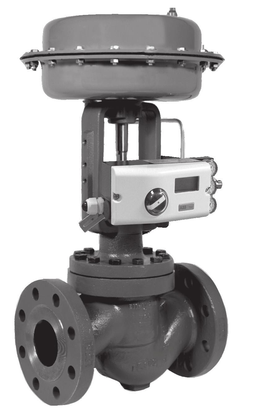
4 INFORMATION PRESENT ON CONTROL VALVES There is a great deal of information present on each control valve ranging in importance from the part number and serial number to the color of the paint and casting numbers. This information is important for identifying the valve, installing it correctly, and obtaining parts. Examples of the current factory nameplates and flow arrow plates used on Series 5800 control valves are shown here. The accompanying table identifies the information present and where to find it on the control valve. There may also be other casting numbers and foundry marks present that do not provide useful information. Customer specific tagging may also present. The plates used, and information present, on Warren Controls other product lines or older valves may be different, contact the factory for details. ACTUATOR NAMEPLATES FLOW ARROW PLATES DL49 2-WAY FLOW VBA NAMEPLATES DL84 INDUSTRIAL VBA DL115 & CL Emrick Blvd Bethlehem, PA USA _IOM_RevB_0317
5 INFORMATION PRESENT ON CONTROL VALVE PART NUMBER & SERIAL NUMBER Information Symbol(s) Location Notes Part number (Configuration) P/N On actuator On Actuator Nameplate attached to actuator. Serial number S/N On actuator and valve body FLOW DIRECTION(S) Information Symbol(s) Location Notes Flow direction through valve On valve body INPUT SIGNAL, SUPPLY & SERVICE Information Symbol(s) Location Notes On Actuator Nameplate attached to actuator. Sales order number only stamped on flat boss on valve body between end connections 5800).* * Number stamped using approximately 1/8 inch tall characters On Flow Arrow Plate attached to valve body bonnet flange between the end connections.* Input signal SIG On actuator On Actuator Nameplate attached to leg(s) of actuator. Supply pressure VALVE ATTRIBUTES SUP or SUPPLY On actuator Information Symbol(s) Location Notes Maximum temperature rating of valve body Trim Cv (flow coefficient) Trim style (Characteristic) Trim material Valve body material TMAX or Tmax Cv CHAR TRIM MATL On actuator and valve body On valve body On valve body On valve body On valve body On Actuator Nameplate attached to leg(s) of actuator. On Actuator Nameplate attached to leg(s) of actuator. On Industrial VBA Nameplate attached to valve body bonet flange between the end connections on side oposite flow arrow plate. On Industrial VBA Nameplate attached to valve body bonet flange between the end connections on side oposite flow arrow plate. On Industrial VBA Nameplate attached to valve body bonet flange between the end connections on side oposite flow arrow plate. On Industrial VBA Nameplate attached to valve body bonet flange between the end connections on side oposite flow arrow plate. If WCB is cast on the valve, and or the factory applied paint is gray, the valve body material is steel. If CF8M is cast on the valve the valve body material is 316 stainless steel. Series _IOM_RevB_0317 5
6 BODY STYLE VERSUS APPLICATION 2-WAY VALVES (Control of Liquids, Gases, and Steam) Way Single Seat Unbalanced Valve with Cage Retained Seat The 5840 Valve is particularly effective for the control of liquids, gases, and steam. It is a suitable solution for applications with dirty fluids and high pressure drops. ANSI Class IV and VI shut-off. Sizes: 1/2, 3/4, 1, 1-1/2, 2, 2-1/2, 3, 4 inch Body: WCB Steel or CF8M Stainless Steel 300 NPT or 300 Socketweld (1/2 thru 2), 150LB Flange or 300LB Flange (1/2 thru 4) Trim: EQ% or Linear, 316 Stainless Steel, TFE, PEEK, or Alloy 6 Wrapped 316 SS, 400 Stainless Steel, Alloy 6 Wrapped 400 SS Shut-off: ANSI Class IV (Stainless Steel and Alloy 6 Trim), ANSI Class VI (TFE and PEEK Trim) Packing & TFE V-Ring, Spring Loaded, w/ PEEK Bearings (+32 Bonnet: to 450 F), TFE V-Ring, Spring Loaded, w/ Z PEEK Bearings (+32 to 450 F), Adjustable Graphite w/ PEEK Bearings (+32 to 450 F), Adjustable Graphite w/ Z PEEK Bearings (+32 to 450 F), Adjustable Graphite w/ Graphite Gaskets & Alloy 6 Bearings (+32 to 550 F), Adjustable Graphite w/graphite Gaskets, Graphalloy Bearings & Extension Bonnet (+32 to 750F for NON-Oxidizing Media ONLY) Adjustable Graphite w/ Graphite Gaskets, Alloy 6 Bearings & Extension Bonnet (+32 to 800 F), Suitable for Oxidizing Media Note: PEEK Bearings are best suited for chemical applications. Z-PEEK Bearings are best suited for water and steam applications. Temperature: +32 to 450 F (TFE or PEEK Trim) +32 to 800 F (Stainless Steel or Alloy 6 Trim) Rangeability: 50: Way Single Seat Caged Balanced Valve with Cage Retained Seat The 5843 is a balanced valve that is an effective solution for the control of liquids, gases, and steam at higher pressures. It requires less force to operate than unbalanced valves so smaller actuators can be used. Its single seat o-ring seal design facilitates ANSI Class IV shut-off. It is limited to cleaner fluids. Sizes: Body: Trim: Shut-off: Packing & Seal Bonnet: 2-1/2, 3, 4 inch WCB Steel, CF8M Stainless Steel 150LB Flange or 300LB Flange EQ% or Linear, 316 Stainless Steel, 400 Stainless Steel, Alloy 6 Wrapped 400 SS ANSI Class IV (Fluoraz Seal) ANSI Class III (Metal Seal) TFE V-Ring, Spring Loaded, w/ PEEK Bearings and Fluoraz (+32 to 450 F), TFE V-Ring, Spring Loaded, w/ Z PEEK Bearings and Fluoraz Seal (+32 to 450 F), Adjustable Graphite w/ PEEK Bearings and Fluoraz Seal (+32 to 450 F), Adjustable Graphite w/ Z PEEK Bearings and Fluoraz Seal (+32 to 450 F), Adjustable Graphite w/ Graphite Gaskets & Alloy 6 Bearings and Fluoraz Seal (+32 to 450 F), Adjustable Graphite w/ Graphite Gaskets, Graphalloy Bearings Metal Seal & Extension Bonnet (+32 to 750F for NON-Oxidizing Media ONLY) Adjustable Graphite w/ Graphite Gaskets, Alloy 6 Bearings Metal Seal, & Extension Bonnet (+32 to 800 F) Note: PEEK Bearings are best suited for chemical applications. Z-PEEK Bearings are best suited for water and steam applications. Temperature: +32 to 800 F (Stainless Steel or Alloy 6 Trim) Rangeability: 50: Emrick Blvd Bethlehem, PA USA _IOM_RevB_0317
7 Way Single Seat Low-Flow Unbalanced Valve with Cage Retained Seat The 5848 Valve is particularly effective for the control of clean, very low flow liquids, gases, and steam. ANSI Class IV and VI leakage ratings standard. See Table on page 40 for Fluid Temperature Limits Sizes: 1/2, 3/4, 1 inch Body: WCB Steel or CF8M Stainless Steel 300 NPT, 300 Socketweld, 150LB Flange or 300LB Flange Trim: Modified Linear: 316 Stainless Steel; TFE or PEEK Leakage Rating: ANSI Class IV (Stainless Steel Trim), ANSI Class VI (TFE and PEEK Trim) Packing, LS EPDM Lip w/ PEEK Bearings Type & L8 EPDM Lip w/ Z PEEK Bearings Bonnet TS TFE V-Ring, Spring Loaded, w/ PEEK Bearings Construction: T8 TFE V-Ring, Spring Loaded, w/ Z PEEK Bearings GS Adjustable Graphite w/ PEEK Bearings G8 Adjustable Graphite w/ Z PEEK Bearings GG Adjustable Graphite w/ Graphite Gaskets, Copper Based Graphalloy Bearings & Extension Bonnet (For NON-Oxidizing Media ONLY, Best Suited for Hot Water and Steam) GL Adjustable Graphite w/ Graphite Gaskets, Nickel Based Graphalloy Bearings & Extension Bonnet (For NON-Oxidizing Media ONLY, Best Suited for Heat Transfer Oils) G7 Adjustable Graphite w/ Graphite Gaskets, Oxidation Resistant Graphalloy Bearings & Extension Bonnet (For Oxidizing Media ONLY) Note: PEEK Bearings are best suited for water and chemical applications. Z-PEEK Bearings are best suited for steam applications. Rangeability: 40:1 for Cv :1 for Cv :1 for Cv 0.25 Flow direction is reversed when used with Cylinder Actuator Failed Closed ALLOWABLE SEAT LEAKAGE CLASSES Leakage Class Maximum Seat Leakage Test Fluid Test Pressure Relative Seat Tightness Class II 0.5% of rated CV Water 45 to 60 PSI 1 Class III 0.1% of rated CV Water 45 to 60 PSI 5 Class IV** 0.01% of rated CV Water 45 to 60 PSI 50 Class V ml /min/inch of trim size/ P(PSI) Water Max Operating P 300,000 Class VI** Class VI about 0.9 ml/min * Air 50 PSI 600,000 Flow direction is reversed when used with Cylinder Actuator BODY PRESSURE-TEMPERATURE RATINGS: 150 FLG Steel 300 NPT, SWE, or FLG Steel 150 FLG St Steel 300 NPT, SWE, or FLG St Steel Temperature (F) +32 To 100 F Pressure ratings are PSIG For applications below 32 consult factory Body Pressure Temperature Ratings conform to ANSI based on body/ flange rating and body material. As the fluid temperature increases, the maximum allowable internal pressure decreases. Verify maximum pressures and temperatures prior to selecting body material and body/flange rating. FLOWING DIFFERENTIAL TRIM MATERIALS PRESSURE LIMIT 316 Stainless Steel 100 PSID TFE 100 PSID PEEK 100 PSID 400 Stainless Steel 200 PSID Alloy PSID NOTE: Approaching limits for continuous use will reduce trim life. For continuous use, stay within half of rated maximum. NOTE ON BEARINGS: PEEK Bearings should not be used for temperatures above 450ºF or flowing differential pressure above 300 PSIG. * Leakage rate varies by valve size, Refer to the ANSI/FCI Standard **Class IV and V are the ONLY leakage classes available within the 5800 Series. Series _IOM_RevB_0317 7
8 DIMENSIONS & WEIGHTS DIMENSION (IN) 5840 VALVE SIZE (IN) 1/2 3/ / / THD 7-1/2 7-5/8 7-3/4 9-1/4 10-1/2 NA NA NA A 300SWE 7-1/2 7-5/8 7-3/4 9-1/4 10-1/2 NA NA NA 150FLG 71/4 7-1/4 7-1/4 8-3/ /8 11-3/4 13-7/8 300FLG 7-1/2 7-5/8 7-3/4 9-1/4 10-1/2 11-1/2 12-1/2 14-1/2 B 2 2-3/8 2-1/2 3-1/4 3-3/ /8 5-1/4 C Standard /8 4-7/ Extension Bonnet /8 9-7/ VALVE WEIGHT (LB) SIZE Standard With Extension Bonnet (IN) 300THD 300SWE 150FLG 300FLG 300THD 300SWE 150FLG 300FLG 1/ / / /2 NA NA NA NA NA NA NA NA NA Consult factory for drawings, weights, and dimensions of fonfigurations not shown. Actual shipping weights may vary. DIMENSION (IN) 5843 VALVE SIZE (IN) 2-1/ FLG 10-7/8 11-3/4 13-3/8 A 300FLG 11-1/2 12-1/2 14-1/2 B 4 4-3/8 5-1/4 Standard C Extension Bonnet WEIGHT (LB) VALVE SIZE Standard With Extension Bonnet (IN) 150FLG 300FLG 150FLG 300FLG 2-1/ Face to face dimensions for NPT & SWE conform to ANSI/ISA S # (sizes 1/2 and 3/4 inch) and S75.12 Short 300# (Sizes 1 thru 2 inch) 150 & 300FLG conform to ANSI/ISA S75.03 A Valve shown with DL84 Actuator as typical. For additional actuator information see Series 5800 Product Specification and the Installation Operation and Maintenance Instructions for the actuator in use. C B NA = Not Available DIMENSION (IN) VALVE SIZE (IN) /2 3/ THD 7-1/2 7-5/8 7-3/4 A 300SWE 7-1/2 7-5/8 7-3/4 150FLG 7-1/4 7-1/4 7-1/4 300FLG 7-1/2 7-5/8 7-3/4 B 2 2-3/8 2-1/2 Standard C Extension Bonnet VALVE SIZE WEIGHT (LB) Standard With Extension Bonnet (IN) 300THD 300SWE 150FLG 300FLG 300THD 300SWE 150FLG 300FLG 1/ / Consult factory for drawings, weights, and dimensions of configurations not shown. Actual shipping weights may vary Emrick Blvd Bethlehem, PA USA _IOM_RevB_0317
9 INSTALLATION See also separate actuator and accessory instructions for additional installation guidelines.! Check valve for any damage due to improper storage or transportation. Immediately notify your sales organization of any damaged goods upon receipt. Do not attempt to move or disturb the valve further so photos may be taken. If the shipping container is noticeably damaged refuse receipt, as the shipping company should be held liable until a shipping representative is available to take photos. Be sure that the flow medium, ambient temperature and the selected location will not exceed the maximum temperature of the valve, actuator, or accessories. Information can be found in the product specifications and on the nameplate(s) regarding these limits (See Information Present on Control Valves section for location of important information on valve). Follow good piping practices. Install a bypass around the valve. Install stop valves in inlet and outlet piping to provide means to isolate valve. A straight run of pipe is recommended for 10 pipe diameters upstream of the valve and 20 pipe diameters downstream of the valve. Protect valve and downstream equipment with a self-cleaning strainer. Provide proper inlet and outlet drainage in steam service to prevent water hammer or possible erosion in equipment. Install gauges in inlet and outlet piping to provide means for checking adjustment and operation. For maximum efficiency and minimum wear install valve in vertical position with the stem pointing upward. Actuators mounted in any position other than vertical must be supported independent of the valve. DO NOT MOUNT DL115 ACTUA- TORS IN THE HORIZONTAL POSITION. Be sure to leave clearance to allow for actuator removal (See Dimensions & Weights of Product Specification section for actuator removal clearance). Before installing, be sure valve and piping are clean inside and free of scale, chips, welding spatter, and foreign material. Thoroughly blow out or flush pipe lines. The valve must be installed with the fluid flowing in the correct direction(s). For proper operation in all applications, control valves must be piped according to the corresponding flow arrows, inlet markings, and port markings present on each valve (See Information Present on Control Valves section for location of important information on valve). Pipes must be aligned squarely with the valve at each connection. If the valve has screwed ends, do not apply pipe dope to the threads of the valve body or to the first two threads of the pipe. If the valve has flanged ends, tighten flange bolts evenly to prevent excessive stress and the possibility of cracking. Series _IOM_RevB_0317 9
10 INSTALLATION (CONT.) If the valve has welded ends, prevent plug and cage distortion by keeping excess heat from the body. The valve, actuator, and accessories (if so equipped) are assembled, tested, and calibrated at the factory. The actuator nameplate specifies set-up parameters used (See Information Present on Control Valves section for location of important information on valve). Do not exceed the supply pressure listed on the actuator nameplate or you will damage the valve and void the warranty. Supply air, or voltage instrument signal, and accessories should be connected to ports or terminals as indicated on the control valve. Final tuning may be required under actual operating conditions. On critical or dangerous equipment, provide suitable safety and emergency systems to protect personnel and property from injury due to a valve malfunction. If the valve handles flammable, toxic, corrosive or explosive fluids, provide for safety in the event of valve leakage or malfunction. Do not obscure flow arrow plates or nameplates with paint. If flow arrow plates or nameplates will be covered with insulation, it is recommended the information on the plates be transcribed on the outside of the insulation in the same location as the plate. OPERATION Close inlet and outlet stop valves. Check that valve responds through rated travel in relation to changes in input signal. Rated travel is shown by position of travel indicator on valve stem relative to travel indicator on yoke. For valves fitted with a handwheel, manually operate valve with no air applied, using handwheel through rated travel to check freedom of movement. Return handwheeel to its standby position. Place valve in operation Emrick Blvd Bethlehem, PA USA _IOM_RevB_0317

11 MAINTENANCE Series 5800 Compact Globe Control Valves are for the most part maintenance free when properly selected and installed. Rebuilding of these valves should not be necessary under normal operating conditions. For best operation follow installation guidelines (See Installation section); maintain the fluid pressure, temperature, flow, flowing differential pressure, and shut-off differential pressure within the limits of the valve (See Series 5800 Product Specification for details). In installations where high vibration exists, pneumatic and/or electrical connections should periodically be checked for integrity. In water or water and glycol applications, good water quality must be maintained or the service life of the valve may be reduced (See Water Quality Guidelines). The valve stem must be kept free of debris, deposits, dirt, dust, and scratches or the packing parts may be damaged resulting in a packing leak. Control valve hunting will cause excessive stroking of the valve stem and result in premature failure of the packing seal. The system must be stabilized to prevent hunting to ensure reasonable packing life and optimal control performance. Oversizing of a control valve will result in an unstable condition, which can cause noise, vibration, and premature trim and packing seal failure. The use of Warren Controls ValveWorks sizing program will facilitate the selection of the optimum valve. PACKING ADJUSTMENT Series 5800 Compact Globe Control Valves have adjustable packing. If a packing leak is observed tighten the packing nut ¼ turn and observe. If the leak continues tighten the packing nut another ¼ turn and observe. Repeat as necessary. If the leak continues and the packing nut cannot be tightened further with reasonable force replace the packing and if necessary the stem and plug assembly. PARTS/ OVERHAUL Damaged or worn parts can decrease performance and shorten valve life. Damaged or worn packing parts including the packing, bearings, spring, and other bonnet parts can cause a packing leak resulting in damage to the actuator, accessories, and surrounding equipment. Damaged or worn packing parts can also cause increased hysteresis resulting in poor control. Damaged or worn trim parts including the plug, seat ring, stem, cage, o-ring, piston ring, cage spring, seat gasket, and bearing can cause increased hysteresis, poor control, excessive internal leakage, and poor shut-off. Damaged or worn trim parts can also cause damage to the packing parts resulting in a packing leak Damaged or worn body gaskets or o-ring seals can cause external leakage resulting in damage to the actuator, accessories, and surrounding equipment. Should parts become worn or damaged, parts kits are available. Repack Kits are available to replace the packing. Repack/ Inspection Kits are available to allow the valve to be opened for inspection of its internal parts. Rebuild/Repack Kits are available to completely rebuild/ overhaul the valve. Parts kits come with complete step-by-step instructions. Each kit has its own part number. Please provide the valve s serial number to ensure getting the correct kit part number and correct parts.! DO NOT ATTEMPT TO SERVICE WITHOUT A REPACK/INSPECTION KIT & SUPPLEMENTAL INSTRUCTIONS. Series _IOM_RevB_
12 PARTS KITS FOR TS, T8, & V8 PACKING TYPE & BONNET CONSTRUCTION REPACK KITS INCLUDE ITEM QTY DESCRIPTION ITEM QTY DESCRIPTION 2 1 PACKING NUT 9 1 PACKING SPRING 3 2 STEM WIPER 11 1 PACKING BOX RING 5 1 PACKING RETAINER 13 1 WIPER RETAINER 6 1 SLEEVE BEARING 1 TUBE STEM LUBE 7 1 V-RING PACKING SET 1 TUBE COPPER ANTI SEIZE COMPOUND 8 1 PACKING WASHER FOR GS, G8, GX, & GG PACKING TYPE & BONNET CONSTRUCTION REPACK KITS INCLUDE ITEM QTY DESCRIPTION ITEM QTY DESCRIPTION 2 1 PACKING NUT STEM WIPER (GS, G8) PACKING RETAINER (GS, G8) 27 1 PACKING RING (Valve sizes 1/2 thru 2 inch) PACKING RING (Valve sizes 2-1/2 thru 4 inch) PACKING RING (Valve sizes 2-1/2 thru 4 inch) 6 1 SLEEVE BEARING (GS, G8) 35 1 RETAINER WASHER (GG Valve sizes 1/2 thru 2 inch) 11 1 PACKING BOX RING 36 1 UPPER BEARING AND RETAINER ASSY (GG) 13 1 WIPER RETAINER (GS, G8) TUBE STEM LUBE (GS, G8) 23 BEARING (GH, GX) TUBE COPPER ANTI SEIZE COMPOUND 24 AR PACKING CARTRIDGE (Valve sizes 1/2 thru 2 inch) TUBE NICKEL ANTI SEIZE COMPOUND (GH, GG) 25 1 SPACER 5840 REPACK/INSPECTYION KITS INCLUDE ITEM QTY DESCRIPTION ITEM QTY DESCRIPTION 14 1 BONNET GASKET 21 1 SEAT GASKET 15 2 CAGE SPRING 1 REPACK KIT 5840 REPACK/INSPECTYION KITS INCLUDE ITEM QTY DESCRIPTION ITEM QTY DESCRIPTION 14 1 BONNET GASKET 21 1 SEAT GASKET 15 1 CAGE SPRING 1 TUBE O-RING LUBE All Packing Type & Bonnet Constructions EXCEPT (GX, GG) O-RING All Packing Type & Gonnet Constructions EXCEPT (GX, GG) PISTON RING Packing Type & Gonnet Constructions EXCEPT (GX, GG) 1 REPACK KIT Emrick Blvd Bethlehem, PA USA _IOM_RevB_0317
13 PARTS KITS 5840 REBUILD/REPACK KITS INCLUDE ITEM QTY DESCRIPTION ITEM OTY DESCRIPTION 1 1 VALVE STEM BONNET GASKET CAGE SPRING FLANGED BEARING (All Packing Type & Bonnet Constructions EXCEPT GX, GG) PLUG SEAT RING SEAT GASKET BEARING Packing Type & Bonnet Construction (GX, GG) RETAINING RING (Packing Type & Construction (GX, GG) DISC HOLDER Trim Material T & P Trim size DISC Trim Material T & P Trim size DISC RETAINER Trim Material T & P Trim size SELF-LOCKING NUT Trim Material T & P Trim size INSERT Trim Material T & P Trim size RETAINER Trim Material T & P Trim size REPACK KIT 5843 REBUILD/REPACK KITS INCLUDE ITEM QTY DESCRIPTION ITEM OTY DESCRIPTION 1 1 VALVE STEM 19 1 PLUG 14 1 BONNET GASKET 20 1 SEAT RING 15 1 CAGE SPRING 21 1 SEAT GASKET 16 1 FLANGED BEARING O-RING All Packing Type & Bonnet Constructions EXCEPT (GX, GG) PISTON RING Packing Type & Bonnet Constructions EXCEPT (GX, GG) CAGE REPACK KIT 1 BEARING Packing Type & Bonnet Construction (GX, GG) RETAINNG RING Packing Type & Bonnet Construction (GX, GG) TUBE O-RING LUBE All Packing Type & Bonnet Constructions EXCEPT (GX, GG) Series _IOM_RevB_
14 Emrick Blvd Bethlehem, PA USA _IOM_RevB_0317
15 Series _IOM_RevB_
16 SERIES: 5843 Construction Details Emrick Blvd Bethlehem, PA USA _IOM_RevB_0317
17 CODE S & 8 CODE S & 8 CODES GS, GH & G8 Series _IOM_RevB_
18 Emrick Blvd Bethlehem, PA USA _IOM_RevB_0317
19 5840 CONSTRUCTION DETAILS BODY MATERIALS CODE W WCB BODY 4 YOKE LOCKNUT PLEATED STEEL 10 HEX HEAD CAPSCREW ALLOY STEEL GR B7 12 BONNET STEEL A216 WCB 22 VALVE BODY STEEL A216 WCB CODE F CF8M BODY 4 YOKE LOCKNUT 300 SERIES SST 10 HEX HEAD CAPSCREW SST GR B8M CLASS 2 12 BONNET SST A351 CF8M 22 VALVE BODY SST A351 CF8M TRIM MATERIALS CODE S 316 STAINLESS STEEL TRIM 1 VALVE STEM 316 SST 18 CAGE 316 SST 19 PLUG 316 SST 20 SEAT RING 316 SST CODE T TFE SOFT SEATS 1 VALVE STEM 316 SST 18 CAGE 316 SST 20 SEAT RING 316 SST 29 DISC HOLDER 316 SST 30 DISC REINFORCED PTFE 31 DISC RETAINER 316 SST 32 SELF-LOCKING NUT 18-8 SST 33 INSERT REINFORCED PTFE 34 RETAINER 316 SST CODE P PEEK SOFT SEATS 1 VALVE STEM 316 SST 18 CAGE 316 SST 20 SEAT RING 316 SST 29 DISC HOLDER 316 SST 30 DISC REINFORCED PEEK 31 DISC RETAINER 316 SST 32 SELF-LOCKING NUT 18-8 SST 33 INSERT REINFORCED PEEK 34 RETAINER 316 SST CODE 6 ALLOY 6 WRAPPED 316 STAINLESS STEEL TRIM 1 VALVE STEM 316 SST 18 CAGE 316 SST 19 PLUG 316 SST/ALLOY 6 INLAY 20 SEAT RING 316 SST/ALLOY 6 INLAY CODE STAINLESS STEEL TRIM 1 VALVE STEM 316 SST 18 CAGE 316 SST 19 PLUG 400 SST 20 SEAT RING 400 SST CODE 6 ALLOY 6 WRAPPED 316 STAINLESS STEEL TRIM 1 VALVE STEM 316 SST 18 CAGE 316 SST 19 PLUG 400 SST/ALLOY 6 INLAY 20 SEAT RING 316 SST/ALLOY 6 INLAY PACKING TYPE CODE T TEFLON V-RING PACKING & V TEFLON V-RING PACKING VACUUM SERVICE 7 V-RING PACKING SET PTFE 8 LOAD WASHER 316 SST 9 PACKING SPRING 316 SST Series _IOM_RevB_
20 5840 CONSTRUCTION DETAILS (CONT.) CODE G GRAPHITE PACKING 24 PACKING CARTRIDGE DIE-FORMED GRAPHITE 25 SPACER 316 SST 26 PACKING RING BRAIDED GRAPHITE 27 PACKING RING DIE-FORMED GRAPHITE BONNET CONSTRUCTION CODE H ALLOY 6B BEARINGS 2 PACKING NUT 316 SST 11 BOX RING 316 SST 14 BONNET GASKET GRAPHITE 15 CAGE SPRING INCONEL/GRAPHITE 16 FLANGED BEARING ALLOY 6B 21 SEAT GASKET GRAPHITE 23 BEARING ALLOY 6B 26 PACKING RING BRAIDED GRAPHITE CODE S PEEK BEARINGS 2 PACKING NUT 316 SST 3 STEM WIPER GRAPHITE FILLED TFE/SST 5 PACKING RETAINER 316 SST 6 SLEEVE BEARING REINFORCED PEEK 11 BOX RING 316 SST 13 WIPER RETAINER 316 SST 14 BONNET GASKET NONASBESTOS 15 CAGE SPRING 316 SST/PTFE 16 FLANGED BEARING REINFORCED PEEK 21 SEAT GASKET NONASBESTOS CODE X ALLOY 6B BEARINGS W/ EXTENSION BONNET 2 PACKING NUT 316 SST 11 BOX RING 316 SST 12 EXTENSION BONNET AS SPECIFIED 14 BONNET GASKET GRAPHITE 15 CAGE SPRING INCONEL/ GRAPHITE 16 FLANGED BEARING ALLOY 6B 21 SEAT GASKET GRAPHITE 23 BEARING ALLOY 6B 26 PACKING RING BRAIDED GRAPHITE 28 RETAINING RING 316 SST CODE 8 Z PEEK BEARINGS 2 PACKING NUT 316 SST 3 STEM WIPER GRAPHITE FILLED TFE/SST 5 PACKING RETAINER 316 SST 6 SLEEVE BEARING REINFORCED PEEK 11 BOX RING 316 SST 13 WIPER RETAINER 316 SST 14 BONNET GASKET NONASBESTOS 15 CAGE SPRING 316 SST/PTFE 16 FLANGED BEARING Z PLASTIC (PEEK BASE) 21 SEAT GASKET NONASBESTOS CODE G GRAPHALLOY BEARINGS W/ EXTENSION BONNET 2 PACKING NUT 316 SST 11 BOX RING 316 SST 12 EXTENSION BONNET AS SPECIFIED 14 BONNET GASKET GRAPHITE 15 CAGE SPRING INCONEL/ GRAPHITE 16 FLANGED BEARING ALLOY 6B 21 SEAT GASKET GRAPHITE 23 BEARING GRAPHALLOY 26 PACKING RING BRAIDED GRAPHITE 28 RETAINING RING 316 SST 35 RETAINER WASHER 316 SST 36 UPPER BEARING AND RETAINER SUBASSY 316 SST/ GRAPHALLOY Emrick Blvd Bethlehem, PA USA _IOM_RevB_0317
21 5843 CONSTRUCTION DETAILS BODY MATERIALS CODE W WCB BODY 4 YOKE LOCKNUT PLEATED STEEL 10 HEX HEAD CAPSCREW ALLOY STEEL GR B7 12 BONNET STEEL A216 WCB 22 VALVE BODY STEEL A216 WCB PACKING TYPE CODE T TEFLON V-RING PACKING & V TEFLON V-RING PACKING VACUUM SERVICE 7 V-RING PACKING SET PTFE 8 LOAD WASHER 316 SST 9 PACKING SPRING 316 SST CODE F CF8M BODY 4 YOKE LOCKNUT 300 SERIES SST 10 HEX HEAD CAPSCREW SST GR B8M CLASS 2 12 BONNET SST A351 CF8M 22 VALVE BODY SST A351 CF8M CODE G GRAPHITE PACKING 24 PACKING CARTRIDGE DIE-FORMED GRAPHITE 25 SPACER 316 SST 26 PACKING RING BRAIDED GRAPHITE 27 PACKING RING DIE-FORMED GRAPHITE TRIM MATERIALS CODE S 316 STAINLESS STEEL TRIM 1 VALVE STEM 316 SST 18 CAGE 316 SST 19 PLUG 316 SST 20 SEAT RING 316 SST CODE STAINLESS STEEL TRIM 1 VALVE STEM 316 SST 18 CAGE 400 SST 19 PLUG 400 SST 20 SEAT RING 400 SST CODE 8 ALLOY 6 WRAPPED 400 STAINLESS STEEL TRIM 1 VALVE STEM 316 SST 18 CAGE 400 SST 19 PLUG 400 SST SST/ALLOY 6 INLAY 20 SEAT RING 316 SST SST/ALLOY 6 INLAY Series _IOM_RevB_
22 5843 CONSTRUCTION DETAILS (Cont.) BONNET CONSTRUCTION CODE S PEEK BEARINGS 2 PACKING NUT 316 SST 3 STEM WIPER GRAPHITE FILLED TFE/ SST 5 PACKING RETAINER 316 SST 6 SLEEVE BEARING REINFORCED PEEK 11 BOX RING 316 SST 13 WIPER RETAINER 316 SST 14 BONNET GASKET NONASBESTOS 15 CAGE SPRING 316 SST/ PTFE 16 FLANGED BEARING REINFORCED PEEK 17 O-RING FLUORAZ 21 SEAT GASKET NONASBESTOS CODE X ALLOY 6B BEARINGS W/ EXTENSION BONNET 2 PACKING NUT 316 SST 11 BOX RING 316 SST 12 EXTENSION BONNET AS SPECIFIED 14 BONNET GASKET GRAPHITE 15 CAGE SPRING INCONEL/ GRAPHITE 16 FLANGED BEARING ALLOY 6B 17 PISTON RING UNS S SEAT GASKET GRAPHITE 23 BEARING ALLOY 6B 26 PACKING RING BRAIDED GRAPHITE 28 RETAINING RING 316 SST CODE 8 Z PEEK BEARINGS 2 PACKING NUT 316 SST 3 STEM WIPER GRAPHITE FILLED TFE/ SST 5 PACKING RETAINER 316 SST 6 SLEEVE BEARING REINFORCED PEEK 11 BOX RING 316 SST 13 WIPER RETAINER 316 SST 14 BONNET GASKET NONASBESTOS 15 CAGE SPRING 316 SST/ PTFE 16 FLANGED BEARING Z PLASTIC (PEEK BASE) 17 O-RING FLUORAZ 21 SEAT GASKET NONASBESTOS CODE H ALLOY 6B BEARINGS 2 PACKING NUT 316 SST 11 BOX RING 316 SST 14 BONNET GASKET GRAPHITE 15 CAGE SPRING INCONEL/GRAPHITE 16 FLANGED BEARING ALLOY 6B 17 O-RING FLUORAZ 21 SEAT GASKET GRAPHITE 23 BEARING ALLOY 6B 26 PACKING RING BRAIDED GRAPHITE CODE G GRAPHALLOY BEARINGS W/ EXTENSION BONNET 2 PACKING NUT 316 SST 11 BOX RING 316 SST 12 EXTENSION BONNET AS SPECIFIED 14 BONNET GASKET GRAPHITE 15 CAGE SPRING INCONEL/ GRAPHITE 16 FLANGED BEARING ALLOY 6B 17 PISTON RING UNS S SEAT GASKET GRAPHITE 23 BEARING ALLOY 6B 26 PACKING RING BRAIDED GRAPHITE 28 RETAINING RING 316 SST 35 RETAINER WASHER 316 SST UPPER BEARING AND SST/ GRAPHALLOY RETAINER SUBASSY Emrick Blvd Bethlehem, PA USA _IOM_RevB_0317
23 NOTES: Series _IOM_RevB_


24 5800_IOM_RevB EMRICK BLVD BETHLEHEM, PA USA DEPENDABLE, RUGGED, PRECISION CONTROL VALVES AND ACCESSORIES
INSTALLATION, OPERATION & MAINTENANCE INSTRUCTIONS
 INSTALLATION, OPERATION & MAINTENANCE INSTRUCTIONS TABLE OF CONTENTS Overview... Cover Valve Information... 2-3 Information Present on Valve...4-5 Body vs. Application... 6 Dimensions & Weights... 7 Installation...8-9
Product Specification
 Product Specification Pnuematic Actuated Industrial Valves Compact Globe Control valves Two-Way, Linear, Steel or Stainless Steel Body Valves for Process and Utility Applications Series: 58OO Sizes: 1/2
58OO SERIES 5800 PRODUCT SPEC PNEUMATIC ACTUATED INDUSTRIAL VALVES COMPACT GLOBE CONTROL VALVES SIZES: 1/2 TO 4 INCHES PRODUCT SPECIFICATION
 PNEUMATIC ACTUATED INDUSTRIAL VALVES COMPACT GLOBE CONTROL VALVES PRODUCT SPECIFICATION SERIES 58OO SIZES: 1/2 TO 4 INCHES 5800 PRODUCT SPEC Two-Way, Linear, Steel or Stainless Steel Body Valves for Process
INSTALLATION, OPERATION & MAINTENANCE INSTRUCTIONS
 INSTALLATION, OPERATION & MAINTENANCE INSTRUCTIONS 377 Float Cage / 326L & 322L lever Valves TABLE OF CONTENTS Overview... Cover General Information... Cover Operation... 4 Installation...4-6 Maintenance...
Installation, Operation & Maintenance Instructions
 Installation, Operation & Maintenance Instructions 377 Float Cage / 326L & 322L lever Valves TABLE OF CONTENTS Overview... Cover General Information... Cover Operation... 4 Installation...4-6 Maintenance...
Product Specification
 Product Specification Pnuematic Actuated Industrial Valves compact Globe control valves Two-Way and Three-Way, Linear, Iron Body Valves for Process and Utility Applications SerieS: 8 5 Size April 2008
LEVEL CONTROLS 313 IOM
 LEVEL CONTROLS 313 IOM 313 OVERFLOW TRAP INSTALLATION, OPERATION & MAINTENANCE INSTRUCTIONS TABLE OF CONTENTS Overview...Cover General Information...Cover Installation...4 Operation...4 Maintenance...4
TYPE 200 IOM - VACUUM BREAKER
 TYPE 200 IOM - VACUUM BREAKER INSTALLATION, OPERATION & MAINTENANCE INSTRUCTIONS TYPE 200 VACUUM BREAKER TABLE OF CONTENTS Overview... COVER General Information... COVER Installation... 4 Operation...
FAIL-SAFE CONTROL VALVE FOR MODULATING CONTROL OF INSTANTANEOUS WATER HEATER & HEAT EXCHANGER APPLICATIONS. ARA - 3-Way,Flanged Steel Mix Valves;
 Fast Electrically Actuated Valves FAIL-SAFE CONTROL VALVE FOR MODULATING CONTROL OF INSTANTANEOUS WATER HEATER & HEAT EXCHANGER APPLICATIONS ARD PRODUCT SPEC MODELS SERIES ARIA SIZES: 1/2 TO 2 INCHES ARA
PNEUMATIC ACTUATED INDUSTRIAL VALVES SERIES:
 PRODUCT SPECIFICATION March 2005 PNEUMATIC ACTUATED INDUSTRIAL VALVES SERIES: 2800 SIZES 1/2 to 2 INCHES Precision Globe Control Valves Two-Way and Three-Way, Reciprocating, Bronze or Stainless Steel Body
PS AMA F (a) 0411 ( )
 0411 ( )") PS AMA F (a) 0411 (4.26.11) Table of Contents Body Style Versus Application...................................... 4 Flow Coefficients (Cv) Versus Travel................................. 4 Shut-Off P Ratings...............................................
PS AMA F (a) 0411 (4.26.11) Table of Contents Body Style Versus Application...................................... 4 Flow Coefficients (Cv) Versus Travel................................. 4 Shut-Off P Ratings...............................................
GVI Series Industrial Globe Valves for Flow Control
 Series Industrial Globe Valves for Flow Control 2-way Flow Control Globe Valves ssured utomations Series Industrial Globe Valves are contructed with rugged carbon steel or stainless steel bodies. They
Python 1500 Series Control Valves. Pneumatic and Electric Actuators PYTHON
 Python 1500 Series Control Valves Pneumatic and Electric Actuators PYTHON - 1500 Series Control Valves Control valves are a key component in any pressure or temperature control application. With the increasing
PYTHON 1500 SERIES CONTROL VALVES. Pneumatic and Electric Actuated
 PYTHON 1500 SERIES CONTROL VALVES Pneumatic and Electric Actuated Table of Contents Features and Benefits... 3 Specifications, Weights, and Dimensions... 4-5 Trim Options and CV Values... 6 Pneumatic Actuators...
DBOY Series Pneumatic Control Valve
 Applications Process control systems for food, pulp and paper, chemical, petrochemical & other industries HVAC systems Feed water and fuel system controls in boiler rooms Packaged systems (OEM) such as
PYTHON 1500 SERIES CONTROL VALVES. Pneumatic and Electric Actuated
 PYTHON 1500 SERIES CONTROL VALVES Pneumatic and Electric Actuated Table of Contents Features and Benefits... 3 Specifications, Weights, and Dimensions... 4-5 Trim Options and CV Values... 6 Pneumatic Actuators...
ELECTRICALLY ACTUATED DOUBLE SEATED IRON - 1 1/2-2
 u APPLICATION: Control of Saturated Steam; Water; Water & Glycol Solutions. Seat Leakage Class ANSI III. u CONSTRUCTION: Body: Trim: Stem: Bonnet: Packing: ANSI B16.15 Iron 250lb.Threaded (NPT) EQ%, 300
PNEUMATIC AND ELECTRIC ACTUATED INDUSTRIAL VALVES SERIES:
 PRODUCT SPECIFICATION August 2005 PNEUMATIC AND ELECTRIC ACTUATED INDUSTRIAL VALVES SERIES: 3800 SIZES 1 to 8 INCHES E-Ball Rotary Control Valves High performance, reduced wear, eccentric plug rotary control
FAIL-SAFE CONTROL VALVE FOR MODULATING CONTROL OF INSTANTANEOUS WATER HEATER & HEAT EXCHANGER APPLICATIONS SERIES MODELS
 Fast Electrically Actuated Valves FAIL-SAFE CONTROL VALVE FOR MODULATING CONTROL OF INSTANTANEOUS WATER HEATER & HEAT EXCHANGER APPLICATIONS SERIES ARIA ADVANCED, RELIABLE, INDUSTRIAL ACTUATOR ARC PRODUCT
Fisher HP Series Control Valves
 Product Bulletin D0635X0 Fisher HP Series Control s HP (Globe ) HPA (Angle ) Balanced High-Temperature Trim Balanced Tight Shutoff Trim Unbalanced Trim Fisher HP Series control valves (figure ) are single-port,
AMB SERIES AMB PRODUCT SPEC. Fast Electrically Actuated Valves PRECISION GOBE CONTROL VALVES SIZES: 1/2 TO 2 INCHES
 Fast Electrically Actuated Valves PRECISION GOBE CONTROL VALVES SERIES AMB SIZES: 1/2 TO 2 INCHES Two-Way and Three-Way, Linear, Steel, Bronze, or Stainless Steel Body Valves for the Process and Utility
BOSS Series D Control Valve
 Applications Process control systems for food, pulp and paper, chemical, petrochemical & other industries HVAC systems Feed water and fuel system controls in boiler rooms Packaged systems (OEM) such as
Python Series Control Valves
 Python - 1500 Series Control Valves Control valves are a key component in any pressure or temperature control application. With the increasing cost of fuel, delivering media in the most efficient way increases
Installation, Operation & Maintenance Instructions
 Installation, Operation & Maintenance Instructions High capacity Pressure Independent Control Valve TABLE OF CONTENTS Overview...COVER Operation... 2 Set Differential Pressure Adjustment... 2 Performance...
29OO SIZES: 2-1/2 TO 10 INCHES
 INDUSTRIAL LINEAR ELECTRICALLY ACTUATED HIGH CAPACITY, GENERAL PURPOSE, GLOBE CONTROL VALVES PRODUCT SPECIFICATION 2900 E PRODUCT SPEC SERIES ILEA 29OO SIZES: 2-1/2 TO 10 INCHES Two-Way & Three Way, Linear
78200/18200 Series LINCOLNLOG Valves Anti-cavitation High Pressure Control Valves
 LINCOLNLOG Valves Anti-cavitation High Pressure Control Valves Featuring High Resistance Multiple Stage LINCOLNLOG Trim Angle Configuration 78200 Globe Configuration 18200 Specification Data CP6020 10/97
28OO ILEA SERIES 2800 E PRODUCT SPEC INDUSTRIAL LINEAR ELECTRICALLY ACTUATED THREADED BODY, GENERAL PURPOSE, GLOBE CONTROL VALVES
 INDUSTRIAL LINEAR ELECTRICALLY ACTUATED THREADED BODY, GENERAL PURPOSE, GLOBE CONTROL VALVES PRODUCT SPECIFICATION 2800 E PRODUCT SPEC SERIES ILEA 28OO SIZES: 1/2 TO 2 INCHES Two-Way and Three Way, Linear
Installation, Operation and Maintenance Instructions
 Installation, Operation and Maintenance Instructions MODEL 5520 June 2002 1.0 GENERAL... 2 Model Number Information... 2 Features... 3 Specifications... 4 Table 1A. Flow Coefficients (C V ), Modified Percent
V1C Series. Pneumatic Control Valves V1C Series Cage-Guided Control Valves. Cage-Guided Control Valve. Features
 V1C Series Cage-Guided Control Valve The V1C cage-guided balanced trim control valve offers high pressures and tight shutoff with the use of standard spring/diaphragm actuators. The balanced cage trim
Mounting and Operating Instructions EB 8111/8112 EN. Valve Series V2001 Globe Valve Type 3321
 Valve Series V2001 Globe Valve Type 3321 Fig. 1 Type 3321 Valve with mounted rod-type yoke for pneumatic or electric actuators (partial view) Mounting and Operating Instructions EB 8111/8112 EN Edition
Series V2001 Valves Clean Tech Type 3321CT Globe Valve with pneumatic actuator
 Series V2001 Valves Clean Tech Type 3321CT Globe Valve with pneumatic actuator DIN version Application Compact control valve for the process industry Valve size DN 15 to 50 Pressure rating PN 16 to 40
INTRODUCTION BODY SUB-ASSEMBLY (FIGURE 1) 2 G X L GLOBE CONTROL VALVE VALTEK SULAMERICANA. Top entry assembly: quick and easy maintenance
 2 G X L GLOBE CONTROL VALVE VALTEK SULAMERICANA. Top entry assembly: quick and easy maintenance") globe control valve INTRODUCTION The GXL globe control valve was developed as a simple, lightweight and more economical alternative to the renowned and advanced design of the Valtek Sulamericana GLS globe
globe control valve INTRODUCTION The GXL globe control valve was developed as a simple, lightweight and more economical alternative to the renowned and advanced design of the Valtek Sulamericana GLS globe
Distributed By: M&M Control Service, Inc
 Control Valves DESIGN & OPERATION Description A control valve is a device capable of modulating flow at varying degrees between minimal flow and full capacity in response to a signal from an external control
KOSO HAMMEL DAHL. Specifications. Body Size: Globe - 1/2" through 6" ( mm). Angle - 1/2" through 2" (15-50 mm).
. Angle - 1/2 through 2 (15-50 mm).") control valves KOSO HAMMEL DAHL B U L L E T I N G 1 3 0-1 FEATURES Cage-retained quick change seat ring simplifies maintenance. Metal seats for a variety of services and ANSI IV and V shutoff. Soft seat
control valves KOSO HAMMEL DAHL B U L L E T I N G 1 3 0-1 FEATURES Cage-retained quick change seat ring simplifies maintenance. Metal seats for a variety of services and ANSI IV and V shutoff. Soft seat
Air Operated Valve Control Valve
 Air Operated Valve Control Valve -1 Step 0 Type/Structure/Features Please refer to this for structure and feature of Air Operated Valve and Control Valve. Step 1 Selection Please look at the ID chart to
Control Valves for General Applications
 Control Valves for General Applications 2 CCI s 8G/8H delivers superior control performance and reliability. The series 8 cage-guided valve is specially designed using recent advancements in control valve
Design CP Control Valve with ENVIRO-SEAL Bellows Seal Bonnet
 Instruction Manual Form 5410 November 1998 Design CP/ENVIRO-SEAL Bellows Seal Design CP Control Valve with ENVIRO-SEAL Bellows Seal Bonnet Contents Introduction.............................. 1 Scope of
LESLIE CLASS DLO(S)-2 CAGE-RETAINED TRIM CONTROL VALVES ANSI CLASS
-2 CAGE-RETAINED TRIM CONTROL VALVES ANSI CLASS") LESLIE CLASS DLO(S)-2 CAGE-RETAINED TRIM CONTROL VALVES ANSI 25-300 CLASS Page B Leslie s Class DLO(S)-2 cage-retained control valves are designed for general purpose control of clean, dirty, viscous or
LESLIE CLASS DLO(S)-2 CAGE-RETAINED TRIM CONTROL VALVES ANSI 25-300 CLASS Page B Leslie s Class DLO(S)-2 cage-retained control valves are designed for general purpose control of clean, dirty, viscous or
FAIL-SAFE CONTROL VALVES. Fast Electrically Actuated Control Valves
 Fast Electrically Actuated Control Valves FAIL-SAFE CONTROL VALVES FOR MODULATION CONTROL OF INSTANTANEOUS WATER HEATERS & HEAT EXCHANGER APPLICATIONS ARIA Overview At 2mm/sec travel speed (12 seconds/inch),
Baumann Way Control Valve
 Instruction Manual 24003 Valve Baumann 24003 3-Way Control Valve Contents Introduction... 1 Scope of Manual... 1 Safety Precautions... 2 Educational Services... 3 Maintenance... 3 Installation... 3 Air
3-way 1/2-2 Globe Valves
 Datasheet Overview Designed to work with either an electronic actuator with a 3/4-inch (20 mm) stroke, the three-way globe valves are available in ANSI Class 250 for normally closed or normally open action.
Table of Contents. Automatic Section A B V. Coil Piping Packages A B P P. Water Source Heat Pump Hose Kits A B H K
 Table of Contents Automatic Section Automatic Balance Valves Installation Operation Maintenance Instructions / Warranty Technical Information How To Order Coil Piping Packages Package Types How To Order
Mounting and Operating Instructions EB 8135/8136 EN. Series V2001 Valves Type 3535 Three-way Valve for Heat Transfer Oil
 Series V2001 Valves Type 3535 Three-way Valve for Heat Transfer Oil Type 3535 Three-way Valve with bellows seal and rod-type yoke (partial view) Mounting and Operating Instructions EB 8135/8136 EN Edition
SPIRA-TROL 1/2" to 4" ANSI Two-port LEA, LFA and LLA Control Valves
 1/2" to 4" ANSI Two-port LEA, LFA and LLA Description SPIRA-TROL is a range of two-port single seat globe valves with cage retained seats conforming to ASME/ANSI standards. These valves are available in
SVF FLOW CONTROLS. Series # Flanged Standard Port Fire Safe / API th Edition. Performance Engineered I N C O R P O R A T E D
 Series 41 150# Flanged Standard Port Fire Safe / API-607 4 th Edition 1 PIECE REDUCED PORT BALL VALVE UNITS = INCHES SIZE CLASS 150 WEIGHTS L H W 1 1/2 11 6.50 3.86 9.06 2 21 7.01 4.65 9.06 3 40 7.99 5.98
Flowrite 599 Series Three-Way Valves 1/2 to 2-inch Bronze Body
 Flowrite 599 Series Three-Way s 1/2 to 2-inch Bronze Body Technical Instructions Document No. 155-185P25 VF 599-4 Description The Flowrite VF 599 Series ANSI Class 250 three-way valves are designed to
PNEUMATIC ON OFF GLOBE VALVE
 PNEUMATIC ON OFF GLOBE VALVE Model No. AGE0 SERIES s Bonnet -way globe valve, -way globe valve 1A(1/") ~ 00A(1") JIS 10K~K, ANSI 10#~900#, PN10~, etc. FF, RF, BW, SW Plain bonnet: -17 ~0 Extended bonnet:
Fisher RSS Lined Globe Valve
 Instruction Manual D0990 November 009 RSS Valve Fisher RSS Lined Globe Valve Contents Introduction............................... Scope of Manual.......................... Description...............................
Series A angle pattern control valves
 Series A angle pattern control valves AU: Angle pattern-unbalanced top guided AB: Angle pattern-balanced cage guided AM: Angle pattern-omega multi-path & multi-stage Metso's Neles A series angle pattern
Design HP and HPA 1-through 6-Inch Globe Valves 1- through 2-Inch Angle Valves
 July 99 Bulletin 5.:HP Design HP and HPA -through 6-Inch Globe Valves - through -Inch Angle Valves Design HP (Globe Valve)! Design HPD,! Design HPS, and! Design HPT Design HPA (Angle Valve)! Design HPAD,!
Model 363 Control Valves
 Features Versatility Multiple port sizes make the 363 an easy valve to reconfigure when process applications change. Rugged Design Available severe service trim and high temperature configurations are
CE43 1" (DN25) to 4" (DN100) Carbon Steel Cage Design, Two Port Control Valves
 to 4 (DN100) Carbon Steel Cage Design, Two Port Control Valves") Globe 13 CE43 1" (DN25) to 4" (DN) Carbon Steel Cage Design, Two Port Description The CE43 series is a range of carbon steel two port, cage trim, control valves conforming to ANSI B16.34, ASME VIII standards
Globe 13 CE43 1" (DN25) to 4" (DN) Carbon Steel Cage Design, Two Port Description The CE43 series is a range of carbon steel two port, cage trim, control valves conforming to ANSI B16.34, ASME VIII standards
SPIRA-TROL 1/2" to 4" ANSI Two-port KEA, KFA and KLA Control Valves
 1/2" to 4" ANSI Two-port KEA, KFA and KLA Description SPIRA-TROL is a range of two-port single seat globe valves with cage retained seats conforming to ASME/ANSI standards. These valves are available in
Baumann 24000CVF Carbon & 24000SVF Stainless Steel Flanged Valve Instructions
 Instruction Manual D103360X012 24000CVF/SVF Control Valve Baumann 24000CVF Carbon & 24000SVF Stainless Steel Flanged Valve Instructions CONTENTS Introduction...1 Scope of Manual...1 Safety Precautions...1-2
Control valves with pneumatic actuators up to 350 C PN
 300 540 1080 2 Features Suitable in building and process engineering for various mediums 0...+200 C Suitable with stuffing box extension or stem seal with stainless steel bellow to 10...+350 C and for
Jordan Control Valve Series
 Jordan Control Valve Series Control Valves A control valve is used to manipulate flowing fluids like, gas, water, steam or process solutions. It compensates for changes in flow or pressure and regulates
Baumann 24000C Carbon Steel Little Scotty Control Valve Instructions
 Instruction Manual D103356X012 24000C Control Valve Baumann 24000C Carbon Steel Little Scotty Control Valve Instructions CONTENTS Introduction...1 Scope...1 Safety Precautions...1 Maintenance...2 Flow
Model DF233 Control Valve
 Figure 1 DF233 Control Valve TABLE OF CONTENTS Introduction 2 Body and Packing Reassembly 7 Specifications 3 Fail Closed Actuator Reassembly 8 Valve Sizes 3 Fail Open Actuator Reassembly 9 Unpacking 4
Model DF2000 Control Valve
 Figure 1 DF2000 Control Valve & DFC Actuator TABLE OF CONTENTS Introduction 2 Jam Style Packing - Figure 2 9 General 2 Body Reassembly 7 Scope 2 Seat Ring Installation 7 Specifications 3 Packing Box 7
700 Series Anti-corrosion Control Valves
 7 Series Anticorrosion Control Valves Specification Data CH92 11/97 Split Body PTFE Lined Control Valves for Corrosive Applications Table of Contents Foreword.................................................................
Operating & Maintenance Manual For Steam Conditioning Valve
 For Steam Conditioning Valve 1 Table of Contents 1.0 Introduction 3 2.0 Product description 3 3.0 Safety Instruction 4 4.0 Installation and Commissioning 5 5.0 Valve Disassembly 6 6.0 Maintenance 6 7.0
CONTROL VALVE STANDARD SPECIFICATION
 CONTROL VALVE STANDARD SPECIFICATION QUICK CHANGE TYPE 2-WAY GLOBE VALVE YAD-122Q1 Series http://www.proval.co.kr PROVAL Co., Ltd. [B-1] TOP GUIDE SINGLE SEATED TYPE GENERAL The design of Quick Change
TECHNICAL INSTRUCTIONS #11 REGULATOR Single Seat - Bronze Trim - Composition Disc
 Page 1 TI595CD A Watts Industries Co. TECHNICAL INSTRUCTIONS #11 REGULATOR Single Seat - Bronze Trim - Composition Disc VALVE DESCRIPTION TABLE OF CONTENTS The Powers #11 Regulator is a self-actuating
Baumann Sanitary Angle Control Valve
 Baumann 83000 Sanitary Angle Control Valve Contents Introduction... 1 Scope of Manual... 1 Safety Precautions... 2 Educational Services... 2 Maintenance... 3 Installation... 3 Air Piping... 4 Flow Direction...
TECHNICAL INSTRUCTIONS Heavy Duty Bronze Series
 HEAVY DUTY BRONZE CONTROL S TECHNICAL INSTRUCTIONS Heavy Duty Bronze Series Form TI593UBS HEAVY DUTY BRONZE SERIES DESCRIPTION The Flowrite II Heavy Duty Bronze Series are designed for low cost modulating
Baumann 24000F Wafer Control Valve
 Instruction Manual 24000F Valves Baumann 24000F Wafer Control Valve Contents Introduction... 1 Scope of Manual... 1 Safety Precautions... 2 Maintenance... 2 Installation... 3 Air Piping... 3 Disassembly...
Fisher RSS Lined Globe Valve
 Instruction Manual D0990 RSS Valve July 07 Fisher RSS Lined Globe Valve Contents Introduction... Scope of Manual... Description... Educational Services... Specifications... Installation... Maintenance...
CVS Series H-900, H-1500 and H-2500 Design Valve Bodies
 Instruction Manual CVS Series H-900, H-1500 and H-2500 Design Valve Bodies Introduction Contents Contained in this manual are installation instructions, maintenance procedures and parts information for
I & M 8000 Series. Ideal Installation Schematic. Preferred Installation. Trouble Shooting
 I & M 8000 Series 3170 Wasson Road Cincinnati, OH 45209 USA Phone 513-533-5600 Fax 513-871-0105 lowflow@richardsind.com www.lowflowvalve.com Installation & Maintenance Instructions for 8000 Series Low
Instruction Manual. CVS Series H-900, H-1500 and H-2500 Design Valve Bodies. Contents. Figure 1: Typical CVS Series H Design Body with Trim and Seals
 Instruction Manual CVS Series H-900, H-1500 and H-2500 Design Valve Bodies Contents Contained in this manual are installation instructions, maintenance procedures and parts information for the CVS Series
I & M Mark 708ME. Ideal Installation. Start-Up Procedure. Installation & Maintenance Instructions for Mark 708 & Motor Actuator
 I & M Mark 708ME 3170 Wasson Road Cincinnati, OH 45209 USA Phone 513-533-5600 Fax 513-871-0105 info@richardsind.com www.lowfl owvalve.com Installation & Maintenance Instructions for Mark 708 & Motor Actuator
Forbes Marshall Control Valve. Operational Economy with Optimum Control
 Forbes Marshall Control Valve Operational Economy with Optimum Control Forbes Marshall Control Valve The Forbes Marshall Control Valve provides excellent performance on steam, liquid and gas applications.
Baumann Mikroseal Control Valve
 Instruction Manual 81000 Valve Baumann 81000 Mikroseal Control Valve Contents Introduction... 1 Scope of Manual... 1 Safety Precautions... 2 Maintenance... 3 Installation... 3 Air Piping... 4 Flow Direction...
Product Manual. S&S V-100 Ball Valves 2 though 8 Inch Designs. Introduction: Installation:
 Product Manual S&S V-100 Ball Valves 2 though 8 Inch Designs. Introduction: These instructions apply specifically to the 2 through 8 inch S&S V-100 Ball Valve Bodies. This manual provides maintenance,
Fisher HP Series Control Valves
 HP Valve Product Bulletin Fisher HP Series Control Valves HP (Globe Valve) HPA (Angle Valve) Balanced High-Temperature Trim Balanced Tight Shutoff Trim Unbalanced Trim Fisher HP Series control valves are
D1 Series Top Guided Single Seated Control Valves
 D1 Series Top Guided Single Seated Control Valves Model D1S Overview Model D1S globe control valves are with bolted bonnet and top guided contoured trims. The design facilitates easy access to internal
28000 Series Varipak Control Valves
 GE Oil & Gas Technical Specifications 10/2012 Masoneilan * Valves 28000 Series Varipak Control Valves Precise Microflow Valves with Compact Design and Flexible Capabilities Table of Contents Numbering
Mark 78 Series. Control Valves Mark 78 Globe Style Control Valves. Globe Style Control Valve. Function. Features. CRN Registration Number Available
 Mark 78 Series Globe Style Control Valve The Mark 78 pneumatic control valve is designed for accurate performance and simplified maintenance. This versatile product can be used on a variety of applications,
Model 361 Control Valves
 FEATURES Sour Service Capability Available in standard configurations that comply with NACE MR0175-2002. Versatility A wide range of trim options including Low-Noise make the 361 one of our most versatile
MODEL 5540 CONTENTS. Installation, Operation and Maintenance Instructions 1.0 GENERAL
 Installation, Operation and Maintenance Instructions MODEL 5540 Sep 20 CONTENTS.0 GENERAL. Model Number---------------------------------------------------------------------------------------------------------------
YARWAY HANCOCK Y-PATTERN FORGED STEEL GLOBE STOP VALVES SERIES 4000
 Direct contact and metal-to-metal seating make this Y-pattern globe stop valve ideal for most shut-off applications. FEATURES All valves feature integral Stellite hardfacing on both body and disc seating
Flowrite VF 599 Series Two-Way Valves 2-1/2 to 6-inch Flanged Iron Body
 Flowrite VF 599 Series Two-Way Valves 2-1/2 to 6-inch Flanged Iron Body VF 599-1 Description Features Application The Flowrite VF 599 series two-way valves are designed to work with either a pneumatic
KOMBAT K1 Pneumatic Control Valve
 Applications Bottle Washing Induction Furnaces Machinery Industrial Compressors Steam Tables Cold Storage Boxes Plating Tanks Cooling Ducts Heating Ducts Engine Jacket Cooling Fuel Oil Heaters Liquid Chillers
MODEL 106/206-PG POWER OPERATED GLOBE VALVE Sizes 1/2" to 8" (106-PG) 3" to 10" (206-PG) Installation, Operating and Maintenance Instructions
 3 to 10 (206-PG) Installation, Operating and Maintenance Instructions") MODEL 106/206-PG POWER OPERATED GLOBE VALVE Sizes 1/2" to 8" (106-PG) 3" to 10" (206-PG) Installation, Operating and Maintenance Instructions DESCRIPTION: This valve is the basic component used for most
MODEL 106/206-PG POWER OPERATED GLOBE VALVE Sizes 1/2" to 8" (106-PG) 3" to 10" (206-PG) Installation, Operating and Maintenance Instructions DESCRIPTION: This valve is the basic component used for most
Baumann 24000CVF Carbon & 24000SVF Stainless Steel Flanged Control Valves
 24000CVF and 24000SVF Valves Product Bulletin Baumann 24000CVF Carbon & 24000SVF Stainless Steel Flanged Control Valves The Baumann 24000CVF and 24000SVF line of control valves can be utilized for the
I & M Mark 708. Ideal Installation. Start-Up Procedure. Installation & Maintenance Instructions for Mark 708 & 14M Actuator and Motor Valve
 I & M Mark 708 370 Wasson Road Cincinnati, OH 509 USA Phone 53-533-5600 Fax 53-87-005 info@richardsind.com www.lowflowvalve.com Installation & Maintenance Instructions for Mark 708 & M Actuator and Motor
EC4 SERIES CRYOGENIC VALVES 1/4 2 Sizes
 12501 Telecom Drive, Tampa, FL 33637 Ph: (813) 978-1000 Fax: (813) 977-3329 www.cpc-cryolab.com INSTALLATION, OPERATING, AND MAINTENANCE INSTRUCTIONS 17/2.5.6 Rev. 0 EC4 SERIES CRYOGENIC VALVES 1/4 2 Sizes
General Stem-Guided Control Valves
 Control and Shut-Off Valves Variety of Trim Designs in Different Materials Electric and Pneumatic Actuators as Standard General Stem-Guided Control Valves Sizes ½" - 12" (15mm - 300mm) ANSI Class 150-900
Flowrite VF 599 Series Two-Way Valves 2-1/2 to 6-inch Flanged Iron Body
 Flowrite VF 599 Series Two-Way Valves 2-1/2 to 6-inch Flanged Iron Body VF 599-1 Description Features Application The Flowrite VF 599 series two-way valves are designed to work with either a pneumatic
Mark 70 Series. Sliding Gate Control Valves. Pneumatic Control Valves Mark 70 Sliding Gate Control Valves MARK 70 FEATURES
 Mark 7 Series Sliding Gate Control Valves The MK7 Series is a line of pneumatically-operated diaphragm control valves that combine multiple spring actuators with the precision of Jordan Valve s advanced
General Stem-Guided Control Valves
 Control and Shut-Off Valves Variety of Trim Designs in Different Materials Electric and Pneumatic Actuators as Standard General Stem-Guided Control Valves Sizes ½" - 12" (15mm - 300mm) ANSI Class 150-900
Nor East /9500 Series Double Seated Cage Valves. Instructions. Safety Messages. Inspection. Parts. Nor East Controls Service
 1 12 9200/9500 Series Double Seated Cage Valves Instructions Safety Messages These instructions are intended for personnel who are responsible for installation, operation and maintenance of your Nor East
Technical Data PRESSURE (PSI) DIMENSIONS inches AND WEIGHTS pounds
 DIMENSIONS inches AND WEIGHTS pounds") Technical Data SD 8010A SPENCE ENGINEERING COMPANY, INC. 150 COLDENHAM ROAD, WALDEN, NY 12586-2035 PRINTED IN U.S.A. SD 8010A/0103 G 5" ACTUATOR REMOVAL CLEARANCE F 1/4 NPT A INTIMIDATOR TYPE J CONTROL
Technical Data SD 8010A SPENCE ENGINEERING COMPANY, INC. 150 COLDENHAM ROAD, WALDEN, NY 12586-2035 PRINTED IN U.S.A. SD 8010A/0103 G 5" ACTUATOR REMOVAL CLEARANCE F 1/4 NPT A INTIMIDATOR TYPE J CONTROL
Baumann 24000S Stainless Steel Control Valve
 24000S Valve Product Bulletin Baumann 24000S Stainless Steel Control Valve The Baumann 24000S versatile, pneumatic, control valve may be used for the control of pressure, temperature, level, and flow.
LOW PRESSURE BALANCED VALVE DIAPHRAGM BALANCED
 DIAPHRAGM BALANCED All Rights Reserved. All contents of this publication including illustrations are believed to be reliable. And while efforts have been made to ensure their accuracy, they are not to
Product Manual. CVS Series D Globe and Series DA Angle Style Valves. Introduction. Applications and Features
 Product Manual CVS Series D Globe and Series DA Angle Style Valves Introduction Contained in this manual are installation instructions, maintenance procedures and parts information for the -inch and 2-inch
I & M Mark 78 Series. Ideal Installation. Start-Up. Installation & Maintenance Instructions for Mark 78 Control Valves (1-1/2-2 )
") I & M Mark 8 Series 0 Wasson Road Cincinnati, OH 4509 USA Phone 5-5-5600 Fax 5-8-005 info@richardsind.com www.jordanvalve.com Installation & Maintenance Instructions for Mark 8 Control Valves (-/ - ) Warning:
I & M Mark 8 Series 0 Wasson Road Cincinnati, OH 4509 USA Phone 5-5-5600 Fax 5-8-005 info@richardsind.com www.jordanvalve.com Installation & Maintenance Instructions for Mark 8 Control Valves (-/ - ) Warning:
Installation. I & M Mark EZ Series. Installation & Maintenance Instructions for the Mark EZ Series Globe Style Control Valves
 I & M Mark EZ Series 3170 Wasson Road Cincinnati, OH 45209 Phone 513.533.5600 Fax 513.871.0105 (f) info@richardsind.com www.jordanvalve.com Installation & Maintenance Instructions for the Mark EZ Series
Series W&T Pneumatic Control Valve Type RVG Globe valve and angle valve
 Series W&T Pneumatic Control Valve Type RVG Globe valve and angle valve Application Control valve for feedwater and steam applications in power plant engineering and the petrochemical industry Nominal
HIGH PRESSURE CONTROL VALVE PISTON BALANCED
 PISTON BALANCED All Rights Reserved. All contents of this publication including illustrations are believed to be reliable. And while efforts have been made to ensure their accuracy, they are not to be