Nor East /9500 Series Double Seated Cage Valves. Instructions. Safety Messages. Inspection. Parts. Nor East Controls Service
|
|
|
- Bryce West
- 6 years ago
- Views:
Transcription
1
2 /9500 Series Double Seated Cage Valves Instructions Safety Messages These instructions are intended for personnel who are responsible for installation, operation and maintenance of your Nor East Controls Globe Valve. All safety messages in the instructions are flagged with the word Caution, Warning or Danger. These messages must be followed exactly to avoid equipment damage, personal injury or death. Safety label(s) on the product indicate hazards that can cause equipment damage, personal injury or death. If a safety label becomes difficult to see or read, or if a label has been removed, please contact Nor East Controls for replacement label(s). Personnel involved in the installation or maintenance of valves should be constantly alert to potential emission of pipeline material and take appropriate safety precautions. Always wear suitable protection when dealing with hazardous pipeline materials. Handle valves, which have been removed from service with suitable protection for any potential pipeline material in the valve. Inspection Parts Nor East Controls Service Your Nor East Controls Globe Valve has been packaged to provide protection during shipment. Carefully inspect the unit for damage upon arrival and file a claim with the carrier if damage is apparent. Order parts from your local sales representative, or directly from Nor East Controls, as listed on the back cover. Recommended spare parts are listed on the assembly drawing. These parts should be stocked to minimize downtime. Nor East Controls service personnel are available to install, maintain and repair all Nor East Controls products. Nor East Controls also offers customized training programs and consultation services. For more information, contact your local Nor East Controls sales representative or visit our website at East Controls.com. D Nor East
3 Table of Contents Description Valve Pressure Rating Installation Parts Identification Maintenance Packing Box Connections Valve Overhaul Actuator Removal Valve Disassembly Lapping Plug Valve Re-assembly Packing Replacement Mounting Actuator December 2010 Page 1 D-9200
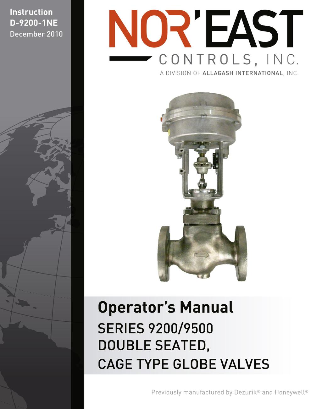
4 Description The Series 9200 valve is a heavy duty, double seated, cage-type globe valve with an available pneumatic diaphragm spring or springless actuator or an electric motor actuator. The Series 9500 valve is a heavy duty, double seated, balanced cage-type plug globe valve with the low-leakage feature of a single-seated valve. The valve does not require an elastomaric O-ring, piston, or special seal rings to meet maximum specification of leakage at shut-off of 0.01% of the maximum Cv rating for the valve. Tested in accordance with FCI Standard 70-2, Class IV. The valve is available with a pneumatic diaphragm spring or springless actuator. This valve is a pressure vessel. Failure to release pipeline pressure may result in personal injury and/or flow system damage. Completely release pipeline pressure before removing the actuator from the valve or removing the valve from the pipeline. Valve Pressure Ratings See Table A for valve pressure ratings. Table A: Valve Pressure Ratings Valve Size 1 1-1/4 1-1/ / Cast Iron (ANSI B16.1) Flanged Ends 125 & 250 lbs Screwed Ends 250 lbs Pressure Rating (ANSI) Carbon Steel & Stainless Steel (ANSI B16.34) Screwed Flanged Ends Ends 150, 300 & 600 lbs 900 lbs 600 lbs December 2010 Page 2 D-9200
5 Installati on If valve is used in a water system, the water must be adequately treated to prevent the formation of rust, carbonates and other undesirable deposits on valve parts. Otherwise, deposit build ups can damage packing, seats or other internal valve parts. For maximum efficiency and minimum wear, install valve in the vertical position with valve stem pointing up. Be sure to leave a minimum of 4-1/4 inches clearance for actuator removal. Before installing, be sure valve and pipeline are clean inside and free of scale, chips and welding spatter. The valve must be installed with the fluid flow in the direction of the arrow on the valve body (pressure under plug). Pipes must be lined squarely with the valve at each connection. If they are forced into the valve, the body may become twisted, causing improper seating. Be sure there are no pockets in the line where condensate could accumulate and cause an undesirable water hammer. Be sure that the flow medium and ambient temperature and the selected location will not exceed the maximum temperature limitations for the valve or actuator. If the valve has screwed ends, do not apply pipe dope or seal tape to the threads of the valve body or to the first two threads of the pipe. If the valve has flanged ends, tighten flange bolts evenly to prevent excessive stress and possible cracking. If the valve has welded ends, prevent plug and cage distortion by keeping excess heat from valve body. Position plug at mid-stroke during welding and heat-treating. December 2010 Page 3 D-9200
6 Installati on Piping Tips for Valves with Screwed Ends Valve held by hex next to pipe. (no twist, no squeeze on valve body). Vise grips hex end next to pipe. Vise holds pipe securely against turning. Parallel jaw wrench grips hex or flats nest to pipe. Effective Length Pipe Size Pipe reamed and cleaned. of Threads 1/2 1/2 3/4 9/ /16 1-1/4 11/16 1-1/2 11/16 2 3/4 Moderate amount of dope. 2-1/2 15/16 (2 threads bare.) 3 1 Piping Tips for Valves with Flanged Ends If possible, mount companion flange on pipe before mounting flange on the valve. Do not apply pipe dope to valve flange, companion flange or gasket. Be sure face of companion flange is flush with face of valve-body flange and lined up square before tightening mounting nuts. Note: If valve has welded ends, prevent plug and cage distortion by keeping excess heat from valve body. December 2010 Page 4 D-9200
7 Parts Nameplate Data The nameplate gives vital information on valve construction and Identification operation. Always reference the serial number when ordering spare parts. The spring range (on spring diaphragm actuators) is factory set to specifications on the order. Note the type of trim material, packing and lubricant number ( NONE means packing does not require lubrication.) Remember that a change in operating conditions may mean a change in trim material, packing and lubricant type. Keep a permanent record of all nameplate information. See Figure 1 for parts identification. 1 - Valve Body 2 - Lantern Ring 4 - Packing Follower 5 - Packing Flange 6 - Packing Flange Nuts Figure 1 Parts Identification 7 - Valve Stem 8 - Lubricator & Isolating Valve 9 - Bonnet 10 - Cage 11 - Plug December 2010 Page 5 D-9200
8 Maintenance Preventive maintenance consists of making a periodic visual inspection. This will reveal packing box leaks, loosening of air connections due to vibration and visible failures of valve parts and accessories. Packing Box Checking packing box for leakage. If leakage is evident; With spring-loaded Teflon packing, replace packing. With non spring-loaded packing, do not tighten packing flange beyond point required to stop leakage. If packing is too tight, excess stem friction is created due to the pressure of the packing against the stem. This excess stem friction may cause the diaphragm top to require several additional pounds of air to stroke valve. If tightening the packing flange nuts fails to stop the leakage, the packing box requires either additional packing or removal of old packing and installation of new packing. Occasional cleaning of the valve stem will keep dirt and grit from being carried into the packing. If lubricated packing is supplied, make regular scheduled checks on lubrication. Replace lubricant as required. See Figure 2 for lubricating packing. 2. Turn lubricator screw in until resistance is felt. 1. Open isolating valve. 3. Close isolating valve. Figure 2 Lubricating Packing Connections Check all mechanical and air connections. In some applications, particularly where the valve is located in a line near a pump, vibrations may cause both mechanical and air connections to work loose. If possible, stroke the valve through several cycles, noting the operation, the pressure required to for stroking and the normal action of the valve. December 2010 Page 6 D-9200
9 Valve Overhaul Generally, when a valve is overhauled the bonnet and actuator are removed from the valve body, the packing is removed from the packing box and all parts are cleaned. Make a thorough inspection of the plug, cage and stem to determine whether these parts should be re-used, re-worked or replaced. To minimize the possibility of leakage, always replace the bonnet and cage gaskets whenever the valve is disassembled. Actuator Removal Stop pipeline flow and completely release pipe line pressure. This valve is a pressure vessel. The bonnet will blow off the actuator if the bonnet bolts are removed with pressure in the valve. Completely release pressure before disassembling the valve. Disconnect and lock out the pneumatic or electrical power to prevent accidental operation of the actuator. Moving parts from accidental operation of power actuator can cause personal injury or equipment damage. Disconnect and lock out power to actuator before removal. Remove actuator from valve. See Figures 3 for actuator removal. December 2010 Page 7 D-9200
10 Valve Overhaul 2. Disconnect pneumatic connection. (Location varies depending on actuator type.) 1. Disconnect stems by removing stem clamp bolts and stem clamp. Remove air pressure. 3. Unscrew yoke locknut and lift actuator off valve. IMPORTANT: For Air-to-Close action, apply enough air pressure to almost close the valve but not seat the plug, to prevent damage. For Air-to-Open action, apply air pressure to lift the plug slightly off the seat to prevent damage. NOTE: For quick inspection of valve trim, remove the bonnet from the valve body with actuator still mounted and attached to the valve stem. If required, cage and gaskets can be removed and replaced. See Disassembly of Plug and Cage section. Figure 3 Actuator Removal (Diaphragm Actuators) December 2010 Page 8 D-9200
11 Valve Overhaul December 2010 Page 9 D-9200
12 Valve Disassembly To disassemble valve, follow steps 1 7. See Figure 5 for step identification. 1. Remove bonnet nuts or cap screws. 2. Lift bonnet, valve stem and plug assembly from body. 3. Loosen packing flange nuts. 4. Rotate plug and stem from bonnet. 5. Remove bonnet and top cage gaskets. 6. Lift cage from valve body. 7. Remove bottom cage gaskets. Nor East Valve Overhaul December 2010 Page 10 D-9200
13 Note: For 1-4 size valves, the bottom cage gasket is spiral wound and top cage gasket is flat. For 6-12 size valves, the bottom cage gasket is flat and top cage gasket is spiral wound Figure 5 Disassembly of Valve December 2010 Page 11 D-9200
14 Valve Overhaul Nor East Series 9500 Plug and Cage As shown in Figure 6, the upper seat of the metal plug contacts the upper seat of the cage slightly before the lower seat does. This upper seat is a tapered flexible metal design. When it flexes slightly, as shown by broken lines on the inset diagram, the lower seat of the plug can make solid contact with the lower cage seat. The lower seat acts as a positive limit stop preventing any over deflection of the upper seat. The actual plug travel is only a few thousands of an inch between the point of initial contact of the top seat and the completely closed position. The double-seated plug has the usual venting holes through the plug that equalizes the pressure on the top and bottom. With the plug pressures balanced, most of the actuator force is used to seat the plug. Figure 6 Series 9500 Plug and Cage Detail December 2010 Page 12 D-9200
15 Valve Overhaul Nor East Lapping Plug (Series 9200 Valves) See Figure 7 for lapping plug instructions. 1. Apply lapping compound to upper and lower seating surfaces of plug and cage. 2. Install bottom cage gasket and cage into valve body. 3. On double-seated valves, check dimension between seats, commonly called IN-to-OUT dimension, before lapping plug. To check the IN-to-OUT dimension, start lapping the plug into the seats; and, after a few laps, examine the plug. If both seating areas of the plug show Iapping marks, continue lapping; but if only one seating area of the plug shows marks, the IN-to-OUT dimension of the plug is less than the IN-to-OUT dimension of the seating surfaces. In this case, the only alternative is to machine a few thousandths of an inch of metal off the seating surface of the plug that shows lapping marks. This will bring the IN-to-OUT dimension on the plug closer to that of the seating surfaces in the cage. After the plug has been machined, follow the same procedure given above to obtain lap marks on both seating areas of the plug. It may be necessary to repeat machining if sufficient metal has not been removed. Lap plug into cage to obtain a good seating surface. Do not remove too much metal from the plug. Stop lapping after a seating surface 1/32 inch (0.8mm) wide is obtained. 4. Be sure to remove all traces of the lapping compound from the plug and cage. Figure 7 Lapping Plug December 2010 Page 13 D-9200
16 Valve Overhaul Valve Re-assembly NOTE: A new plug and cage should be installed at the same time to insure tight shutoff. Always replace required gaskets whenever the valve is disassembled to prevent leakage. If plug and cage have been replaced, refer to Lapping Plug section before proceeding with reassembly. See Figure 7 on page 12. See Packing Replacement section to install new packing. 1. Insert bottom cage gasket into valve body. 2. Insert cage into valve body. It is not necessary to orient the cage to the body. 3. Insert the top cage gasket on top of the cage. 4. Insert the bonnet gasket into the valve body. 5. Insert the plug and stem into the cage. 6. Slide the bonnet down the stem. 7. Finger tighten the bonnet nuts or capscrews. 8. Alternate tightening of the bonnet nuts or capscrews until the bonnet raised face contacts the body on all sides. Tighten to the appropriate torque listed in Table C and Table D. Table C: Bonnet Nuts Torque Steel and Alloy Steel Bodies Stud Size Recommended Torque (Inches-UNC) Lbs.-ft. N-m 7/ / / / / / / Table D: Bonnet Capscrews Torque Cast Iron and Bronze Bodies Stud Size Recommended Torque (Inches-UNC) Lbs.-ft. N-m 7/ / / / / December 2010 Page 14 D-9200
17 Valve Overhaul Nor East Packing Replacement Teflon Graphite or Die Molded Laminated Graphite To replace this packing, it is not necessary to remove the actuator from valve. Disconnect and lock out the pneumatic or electrical power to prevent accidental operation of the actuator. Moving parts from accidental operation of power actuator can cause personal injury or equipment damage. Disconnect and lock out power to actuator before servicing valve. See Figure 8 for Teflon Graphite or Die Molded Laminated Graphite packing identification. 1. Unscrew packing flange nuts. 2. Raise packing flange and packing follower. 3. Remove all packing with standard packing hook. 4. Replace stem if severely scored. (See Disassembly of Plug and Cage section.) 5. Insert new packing into packing chamber. Make sure retaining ring is still in place, then push in 2 Teflon rings, the lantern ring and then 6 more Teflon rings with packing follower. 6. Replace the packing follower and packing flange. Finger tighten the packing flange nuts. 7. Re-connect power to the actuator. Turn on system and check valve for leaks. Packing Flange Packing Follower Teflon Packing (6) Lantern Ring Teflon Packing (2) Retaining Ring Figure 8 - Teflon Graphite or Die Molded Laminated Graphite December 2010 Page 15 D-9200
18 Valve Overhaul Nor East Shredded Teflon - To replace this packing, it is necessary to remove the actuator from valve and stem clamp from valve stem. See Actuator Removal section for instructions to remove actuator. Disconnect and lock out the pneumatic or electrical power to prevent accidental operation of the actuator. Moving parts from accidental operation of power actuator can cause personal injury or equipment damage. Disconnect and lock out power to actuator before servicing valve. See Figure 9 for Shredded Teflon packing identification. 8. Unscrew packing flange nuts. 9. Lift packing flange and packing follower off valve stem. 10. Remove all packing with standard packing hook. Do not remove lantern ring. 11. Insert new packing into packing chamber. Push in 5 Teflon spacers and 4 Teflon packing rings (alternating spacer and packing rings) with packing follower. 12. Replace the packing follower and packing flange. Finger tighten the packing flange nuts. 13. Mount actuator on valve and reconnect power. Turn on system and check valve for leaks. Packing Flange Packing Follower Teflon Packing (4) Teflon Spacers (5) Lantern Ring Figure 9 - Shredded Teflon Packing December 2010 Page 16 D-9200
19 Valve Overhaul Nor East Spring-Loaded Teflon - To replace this packing, it is necessary to remove the actuator from valve and stem clamp from valve stem. See Actuator Removal section for instructions to remove actuator. Disconnect and lock out the pneumatic or electrical power to prevent accidental operation of the actuator. Moving parts from accidental operation of power actuator can cause personal injury or equipment damage. Disconnect and lock out power to actuator before servicing valve. See Figure 10 for Spring-Loaded Teflon packing identification. 1. Unscrew packing flange nuts. 2. Lift packing flange, upper stem wiper, packing follower and packing subassembly bushing off valve stem. 3. Remove all packing with standard packing hook. 4. Remove and clean upper washer, spring, lower washer and lower stem wiper. 5. Replace stem if severely scored. (See Disassembly of Plug and Cage section.) 6. Place a small amount of Plasti-Lube #2 on the Teflon rings and the upper half of the valve stem. 7. Replace lower stem wiper, lower washer, spring and upper washer. 8. Insert new packing into packing chamber. Be careful not to scratch or tear the Teflon rings while sliding over the valve stem. 9. Replace the packing subassembly bushing, packing follower and packing flange. Finger tighten the packing flange nuts. 10. Mount actuator on valve and reconnect power. Turn on system and check valve for leaks. December 2010 Page 17 D-9200
20 Valve Overhaul Nor East Packing Flange Upper Stem Wiper Packing Follower Bushing Packing Subassembly Packing Follower Spring Lower Washer Lower Stem Wiper Figure 10 Spring-Loaded Teflon Packing Mounting Actuator NOTE: Refer to nameplate to determine actuator and valve combination. See Figure 11 for stem connection. Air-to-Close (Direct Acting) Actuator 1. Mount actuator onto bonnet and lock in place with hex socket head cap screws. Slip yoke lock nut over valve stem and tighten down on mounting yoke. 2. With no air pressure in actuator, seat valve plug. 3. Raise valve stem and plug a distance equal to the travel specified on nameplate. 4. Lock valve stem to actuator stem with stem clamp. December 2010 Page 18 D-9200
21 Mounting Actuator Nor East Air-to-Open (Reverse Acting) Actuator 1. Push valve stem down and seat plug. 2. Mount actuator onto bonnet and lock in place with hex socket head cap screws. Slip yoke lock nut over valve stem and tighten down on mounting yoke. 3. Apply sufficient air pressure in actuator to raise actuator stem 1/ Lock valve stem to actuator stem with stem clamp. Actuator Stem Stem Clamp Travel indicator Valve Stem Figure 11 Stem Connection December 2010 Page 19 D-9200
22 Guarantee Products, auxiliaries and parts thereof, of Nor East Controls manufacture, are guaranteed for a period of one year from the date of shipment against defective workmanship and material only, when properly installed, operated and serviced in accordance with Nor East Controls recommendations. Replacement for items of Nor East Controls manufacture will be made free of charge if proved to be defective within such time. No claim for special or consequential damages, transportation, or labor shall be allowed. Purchaser shall be solely responsible for determining suitability for use and in no event shall Nor East Controls be liable in this respect. Equipment or parts manufactured by others but furnished by Nor East Controls will be repaired or replaced, only to the extent provided in the original manufacturer s warranty to Nor East Controls. Nor East Controls does not guarantee resistance to corrosion, erosion, abrasion or other sources of failure, nor does Nor East Controls guarantee a minimum length of service. Failure of the purchaser to give prompt written notice of any alleged defect under this guarantee forthwith upon its discovery, or use and possession thereof after an attempt has been made and completed by someone other than Nor East Controls or an authorized representative to remedy defects therein, or failure to return products or parts for replacement as herein provided, of failure to install, operate, and maintain said products or parts according to instructions provided by Nor East Controls, of failure to pay the entire contract price when due, shall be a waiver of all rights under these representations. The foregoing guarantee shall be null and void, if, after shipment from our factory, the item is modified in any way or component of another manufacturer, such as but not limited to; an actuator is attached to the item by valves & controls other than a Nor East Controls Factory Service Personnel. All orders accepted shall be deemed accepted subject to this guarantee, which shall be exclusive of any other previous guarantee, and this shall be the only effective guarantee or warranty binding on Nor East Controls, anything to the contrary contained in the purchase order, or represented by any agent or employee of Nor East Controls, in writing or otherwise, notwithstanding, including but not limited to implied warranties. THE FOREGOING OBLIGATIONS ARE IN LIEU OF ALL OTHER OBLIGATIONS AND LIABILITIES INCLUDING WARRANTIES OF FITNESS OR MERCHANTABILITY OR OTHERWISE, EXPRESSED OR IMPLIED IN FACT OR BY LAW, AND STATE NOR EAST CONTROLS AND EXCLUSIVE LIABILITY AND PURCHASER S EXCLUSIVE REMEDY FOR ANY CLAIM IN CONNECTION WITH THIS SALE OR FURNISHING OF SERVICES, GOODS, OR PARTS, THEIR OWN DESIGN, SUITABILITY FOR USE, INSTALLATION OR OPERATION. Limitation of Liability In no event shall Nor East Controls be liable for any direct, indirect, special or consequential damages whatsoever, and Nor East Controls liability, under no circumstances, will exceed the contract price for the goods and/or services for which liability is claimed. Any action for breach of contract must be commenced within 1 year after the cause of the action has occurred Riverside Street, Portland, Maine Ph: Fax: Sales and Service Nor East Controls representatives are located in major cities throughout the world. For the name of the representative nearest you, contact: Web site: sales@allagashinternational.com Nor East reserves the right to incorporate our latest design and material changes without notice or obligation. Design features, materials of construction and dimensional data, as described in this bulletin, are provided for your information only and should not be relied upon unless confirmed in writing by Nor East Controls. Certified drawings are available upon request. December 2010 Page 20 D-9200
Nor East. Instructions Safety Messages. Inspection. Parts. DeZURIK Service. Type 05 Pneumatic Actuator Used With Globe Valves
 Instructions Safety Messages These instructions are intended for personnel who are responsible for installation, operation and maintenance of your DeZURIK Actuator. All safety messages in the instructions
Nor East. Instructions. Safety Messages. Inspection. Parts Nor East Controls. Service. Type 05 Air-O-Motor Actuator Used With Globe Valves
 Instructions Safety Messages These instructions are intended for personnel who are responsible for installation, operation and maintenance of your Nor East Controls Actuator. All safety messages in the
DeZURIK KUL KNIFE GATE VALVES
 KUL KNIFE GATE VALVES Instruction D11025 September 2013 Instructions These instructions are intended for personnel who are responsible for the installation, operation and maintenance of your KUL knife
DeZURIK 2-24 (50-600mm) KGN-RSB BI-DIRECTIONAL CAST STAINLESS STEEL KNIFE GATE VALVES
 KGN-RSB BI-DIRECTIONAL CAST STAINLESS STEEL KNIFE GATE VALVES") 2-24 (50-600mm) KGN-RSB BI-DIRECTIONAL CAST STAINLESS STEEL KNIFE GATE VALVES Instruction D11023 October 2016 Instructions These instructions provide information about KGN-RSB Knife Gate Valves. They are
2-24 (50-600mm) KGN-RSB BI-DIRECTIONAL CAST STAINLESS STEEL KNIFE GATE VALVES Instruction D11023 October 2016 Instructions These instructions provide information about KGN-RSB Knife Gate Valves. They are
APCO CRF-100A RUBBER FLAPPER SWING CHECK VALVES
 APCO CRF-100A RUBBER FLAPPER SWING CHECK VALVES Instruction D12043 June 2016 DeZURIK Instructions These instructions provide installation, operation and maintenance information for APCO CRF-100A Rubber
DeZURIK 2 20" BOS BUTTERFLY VALVES
 2 20" BOS BUTTERFLY VALVES Instruction D10459 October 2013 2-20 BOS Butterfly Valves Instructions These instructions provide information about BOS Butterfly Valves. They are for use by personnel who are
APCO ASR-400/450 SEWAGE AIR RELEASE VALVES
 APCO ASR-400/450 SEWAGE AIR RELEASE VALVES Instruction D12005 December 2012 Instructions These instructions provide installation, operation and maintenance information for the APCO ASR- 400/450 Sewage
APCO CSV-1600 SURGE CHECK VALVE
 APCO CSV-1600 SURGE CHECK VALVE Instruction D12022 January 2013 Instructions These instructions provide installation, operation and maintenance information for APCO CSV-1600 Surge Check Valves. They are
DeZURIK 2-24 (50-600mm) KGC ES or HD KNIFE GATE VALVES
 KGC ES or HD KNIFE GATE VALVES") 2-24 (50-600mm) KGC ES or HD KNIFE GATE VALVES Instruction D10411 March 2017 Instructions These instructions are intended for personnel who are responsible for the installation, operation and maintenance
2-24 (50-600mm) KGC ES or HD KNIFE GATE VALVES Instruction D10411 March 2017 Instructions These instructions are intended for personnel who are responsible for the installation, operation and maintenance
DeZURIK AFR3 Filter Regulator Used on Pneumatic Cylinder Actuators
 AFR3 Filter Regulator Used on Pneumatic Cylinder Actuators Instructions D11033 August 2013 Instructions These instructions provide information about AFR3 Filter Regulators. They are for use by personnel
APCO CVS-6000 CONVERTIBLE SWING CHECK VALVES
 APCO CVS-6000 CONVERTIBLE SWING CHECK VALVES Instruction D12009 December 2012 Instructions These instructions provide installation, operation and maintenance information for APCO CVS-6000 Convertible Swing
DeZURIK 2-16" PTW & PFW TAPERED PLUG VALVES
 2-16" PTW & PFW TAPERED PLUG VALVES Instruction D10188 April 2015 Instructions These instructions provide information about Tapered Plug Valves. They are for use by personnel who are responsible for installation,
DeZURIK KGC-MD KNIFE GATE VALVES
 KGC-MD KNIFE GATE VALVES Instruction D11032 February 2018 Instructions These instructions are intended for personnel who are responsible for the installation, operation and maintenance of your KGC-MD knife
DeZURIK 24 and Larger BHP High Performance Butterfly Valves WITH (FB) FYRE-BLOCK SEAT
 FYRE-BLOCK SEAT") 24 and Larger BHP High Performance Butterfly Valves WITH (FB) FYRE-BLOCK SEAT Instruction D10497 April 2015 BHP High Performance Butterfly Valves (S2, S3, S5, AA, HC, ML, T2 & T5 Shafts) Instructions These
24 and Larger BHP High Performance Butterfly Valves WITH (FB) FYRE-BLOCK SEAT Instruction D10497 April 2015 BHP High Performance Butterfly Valves (S2, S3, S5, AA, HC, ML, T2 & T5 Shafts) Instructions These
DeZURIK KSV CL150 & CL300 BONNETLESS KNIFE GATE VALVES
 KSV CL150 & CL300 BONNETLESS KNIFE GATE VALVES Instruction D11021 October 2016 Instructions These instructions provide information about DeZURIK KSV CL150 & CL300 knife gate valves. They are intended for
Recommended spare parts are listed on the assembly drawing. These parts should be stocked to minimize downtime.
 Instruction D10411 July 2018 Instructions These instructions are intended for personnel who are responsible for the installation, operation and maintenance of your KGC knife gate valve, including models
DeZURIK PEC ECCENTRIC VALVES
 3650-7200 PEC ECCENTRIC VALVES Instruction D10019 April 2015 Instructions These instructions provide information about PEC Eccentric Valves. They are for use by personnel who are responsible for installation,
DeZURIK 24" THRU 36" RESILIENT BUTTERFLY VALVES
 24" THRU 36" RESILIENT BUTTERFLY VALVES Instruction D10348 April 2015 Instructions These instructions provide information about DeZURIK 24" thru 36" Resilient Butterfly Valves. They are for use by personnel
DeZURIK VPB V-PORT BALL VALVES
 VPB V-PORT BALL VALVES Instruction D10324 June 2017 Instructions These instructions provide information about. They are for use by personnel who are responsible for installation, operation and maintenance
APCO SRG-6500 SURGE RELIEF GLOBE VALVES
 APCO SRG-6500 SURGE RELIEF GLOBE VALVES Instruction D12020 December 2012 Instructions These instructions provide installation, operation and maintenance information for APCO SRG-6500 Surge Relief Globe
DeZURIK " PEC ECCENTRIC VALVES
 20.5 36" PEC ECCENTRIC VALVES Instruction D10032 April 2015 20.5-36" PEC Eccentric Valves Instructions These instructions provide information about PEC Eccentric Valves. They are for use by personnel who
APCO CVS-250/250A SWING CHECK VALVES
 APCO CVS-250/250A SWING CHECK VALVES Instruction D12003 September 2015 Instructions These instructions provide installation, operation and maintenance information for APCO CVS- 250/250A Swing Check Valves.
CSA products for waste water. Combination air valve. Mod. SCF 2
 CSA products for waste water Combination air valve Mod. SCF 2 Instructions These instructions provide installation, operation and maintenance information for CSA Mod. SCF-2 series waste water air valve.
CSA products for treated water. Water Combination air valve. Mod. FOX 3F RFP and Lynx 3F RFP
 CSA products for treated water Water Combination air valve Mod. FOX 3F RFP and Lynx 3F RFP Instructions These instructions provide installation, operation and maintenance information for CSA water combination
APCO ACS-1200/1700 COMBINATION SLOW CLOSING AIR/VACUUM VALVE
 APCO ACS-1200/1700 COMBINATION SLOW CLOSING AIR/VACUUM VALVE Instruction D12025 December 2012 Instructions These instructions provide installation, operation and maintenance information for APCO ACS- 1200/1700
CSA products for waste water. Anti water hammer combination air valve. Mod. SCF-RFP
 CSA products for waste water Anti water hammer combination air valve Mod. SCF-RFP Instructions These instructions provide installation, operation and maintenance information for CSA Mod. SCF-RFP series
DeZURIK BHP HIGH PERFORMANCE BUTTERFLY VALVE
 BHP HIGH PERFORMANCE BUTTERFLY VALVE Instruction D10503 November 2015 Instructions These instructions provide information about the DeZURIK High Performance Butterfly Valve. They are for use by personnel
January 2016 GLOBE VALVES MIXING & DIVERTING SERIES 8600 MODEL Previously manufactured by Dezurik and Honeywell
 786.89 January 2016 GLOBE VALVES MIXING & DIVERTING SERIES 8600 MODEL 8900 Previously manufactured by Dezurik and Honeywell Description: The Nor East Series 8600 (mixing) and Series 8900 (diverting) cage
SERIES RSR PRESSURE RELIEF VALVE
 SERIES RSR PRESSURE RELIEF VALVE Installation, Operation and Maintenance Manual The Red Valve Series RSR Pressure Relief Valve is a bi-directional valve designed for tough slurry applications. The elastomer
DeZURIK " BAW AWWA BUTTERFLY VALVES WITH EPOXY-RETAINED SEAT
 DeZURIK 20 144" BAW AWWA BUTTERFLY VALVES WITH EPOXY-RETAINED SEAT Instruction D10373 April 2017 Instructions These instructions provide information about the 20 (250 F2 model only) and the 24-144 BAW
Serie 2003/2013. Three-way Control Valve, mixing/diverting. Wörth am Main. Service. Control Valve Division
 Serie 2003/2013 Three-way Control Valve, mixing/diverting Service Preventive maintenance Preventive maintenance primarily consists of making a regular visual inspection of the valve assembly. This can
DeZURIK DR 125 ROTARY DIAPHRAGM ACTUATOR
 DR 125 ROTARY DIAPHRAGM ACTUATOR Instruction D10507 January 2017 Instructions These instructions provide information about. They are for use by personnel who are responsible for installation, operation
DeZURIK SPRING RETURN CYLINDER OPERATOR FOR G-SERIES ACTUATORS USED ON PEF 100% PORT ECCENTRIC VALVES
 SPRING RETURN CYLINDER OPERATOR FOR G-SERIES ACTUATORS USED ON PEF 100% PORT ECCENTRIC VALVES Instruction D10466 December 2012 Instructions These instructions provide information about s. They are for
Operating & Maintenance Manual For Steam Conditioning Valve
 For Steam Conditioning Valve 1 Table of Contents 1.0 Introduction 3 2.0 Product description 3 3.0 Safety Instruction 4 4.0 Installation and Commissioning 5 5.0 Valve Disassembly 6 6.0 Maintenance 6 7.0
Baumann Little Scotty Bronze Control Valve
 Instruction Manual 24000 Valve Baumann 24000 Little Scotty Bronze Control Valve Contents Introduction... 1 Scope of Manual... 1 Safety Precautions... 2 Maintenance... 2 Installation... 3 Air Piping...
CV Control Valves Installation and Operation Manual
 CV1500 - Control Valves Installation and Operation Manual 652-EN Overview Warning: This bulletin should be used by experienced personnel as a guide to the installation of the Armstrong CV1500 Control Valve.
Baumann 24000F Wafer Control Valve
 Instruction Manual 24000F Valves Baumann 24000F Wafer Control Valve Contents Introduction... 1 Scope of Manual... 1 Safety Precautions... 2 Maintenance... 2 Installation... 3 Air Piping... 3 Disassembly...
Series Single seated top guided control valve. Preventive maintenance. Overhauling procedure. Wörth am Main SERVICE NOTE. Control Valve Division
 Series 2000 Single seated top guided control valve Subject to change without notice Fig. 1: Series 2000 valve assembly Preventive maintenance Preventive maintenance consists of making a periodic visual
582 Series. Instruction Manual. Two-Door Wafer Check Valve N-582 (R-08/2016)
") 582 Series Two-Door Wafer Check Valve Instruction Manual N-582 (R-08/2016) Instructions These instructions provide installation, operation and maintenance information for Cla-Val 582 Series. They are for
582 Series Two-Door Wafer Check Valve Instruction Manual N-582 (R-08/2016) Instructions These instructions provide installation, operation and maintenance information for Cla-Val 582 Series. They are for
Baumann Way Control Valve
 Instruction Manual 24003 Valve Baumann 24003 3-Way Control Valve Contents Introduction... 1 Scope of Manual... 1 Safety Precautions... 2 Educational Services... 3 Maintenance... 3 Installation... 3 Air
MetroPrime 22MPC Self-Priming Centrifugal Pump
 Page 1 of 6 prevent priming or reduce pump capacity. OPERATION The 22 MPC-Metropolitan Pump is a self-priming centrifugal pump and only requires priming prior to its initial start. The pump will retain
SLURRY KNIFE GATE VALVE
 SERIES D FLEXGATE SLURRY KNIFE GATE VALVE Installation, Operation and Maintenance Manual The Red Valve Series D Flexgate Slurry Knife Gate Valve is a 100% full bore, truly bi-directional valve designed
DeZURIK CYLINDER OPERATED T-SERIES ACTUATOR
 CYLINDER OPERATED T-SERIES ACTUATOR Instruction D10135 August 2012 Instructions These instructions provide information about s. They are for use by personnel who are responsible for installation, operation
SERIES 5200E Installation, Operation and Maintenance Manual
 SERIES 5200E Installation, Operation and Maintenance Manual The Red Valve Series 5200E Electrically Actuated Control Pinch Valve is a bi-directional valve designed for tough slurry applications. The elastomer
DeZURIK DR 40B ROTARY DIAPHRAGM ACTUATOR
 DR 40B ROTARY DIAPHRAGM ACTUATOR Instruction D10506 October 2016 Instructions These instructions provide information about s. They are for use by personnel who are responsible for installation, operation
CONTENTS. VIKING PUMP, INC. A Unit of IDEX Corporation Cedar Falls, IA USA SECTION TSM 710.1
 TECHNICAL SERVICE MANUAL industrial heavy duty motor speed pumps SERIES 4076 AND 4176 SIZES hle, ate and ale SECTION TSM 710.1 PAGE 1 of 8 ISSUE B CONTENTS Introduction....................... 1 Safety
NE January 2016 SINGLE SEATED CAGE VALVES SERIES 9100 MODEL Previously manufactured by Dezurik and Honeywell
 391.01-3NE January 2016 SINGLE SEATED CAGE VALVES SERIES 9100 MODEL 9101 Previously manufactured by Dezurik and Honeywell Description: Model 9101 valve combines a heavy, duty, single-seated, cage-type
TECHNICAL SERVICE MANUAL
 Electronic copies of the most current TSM issue can be found on the Viking Pump website at www.vikingpump.com TECHNICAL SERVICE MANUAL industrial heavy duty motor speed pumps SERIES 4076 AND 4176 SIZES
CONTROL VALVES SINGLE PORTED CLASSES DL, DDL, DOS, DDOS
 12501 Telecom Drive, Tampa Florida 33637 Installation, Operation and Maintenance 10/1.5.1 Rev. 0 CONTROL VALVES SINGLE PORTED CLASSES DL, DDL, DOS, DDOS TABLE OF CONTENTS INSTALLATION...2 VALVE POSITION...2
NE January 2016 THREE-WAY VALVES SERIES 1600 MODEL 1601 SERIES 1900 MODEL Previously manufactured by Dezurik and Honeywell
 516.01-3NE January 2016 THREE-WAY VALVES SERIES 1600 MODEL 1601 SERIES 1900 MODEL 1901 Previously manufactured by Dezurik and Honeywell Description: Models 1601 and 1901 three-way valves combine with pneumatic,
MODEL 5540 CONTENTS. Installation, Operation and Maintenance Instructions 1.0 GENERAL
 Installation, Operation and Maintenance Instructions MODEL 5540 Sep 20 CONTENTS.0 GENERAL. Model Number---------------------------------------------------------------------------------------------------------------
Baumann 24000C Carbon Steel Little Scotty Control Valve Instructions
 Instruction Manual D103356X012 24000C Control Valve Baumann 24000C Carbon Steel Little Scotty Control Valve Instructions CONTENTS Introduction...1 Scope...1 Safety Precautions...1 Maintenance...2 Flow
DeZURIK TEN-POSITION LEVER MANUAL ACTUATOR
 TEN-POSITION LEVER MANUAL ACTUATOR Instruction D10316 August 2012 Instructions These instructions provide information about Lever Actuators. They are for use by personnel who are responsible for installation,
Tri-Clover Manual and Air Actuated Fractional Valves
 FVSM-99 Tri-Clover Manual and Air Actuated Fractional Valves Series 650 655 660 CONTENTS Thank you for purchasing an Alfa Laval Product! This manual contains disassembly and assembly instructions, maintenance
DeZURIK PNEUMATIC CYLINDER OPERATOR FOR G-SERIES ACTUATORS
 PNEUMATIC CYLINDER OPERATOR FOR G-SERIES ACTUATORS Instruction D10047 March 2017 Instructions These instructions provide information about pneumatic cylinder operators. They are for use by personnel who
Model DF269 Control Valve
 Figure 1 DF269 Control Valve TABLE OF CONTENTS Introduction 2 Fail Open Actuator Disassembly 6 General 2 Body and Packing Reassembly 7 Scope 2 Fail Closed Actuator Resassembly 8 Specifications 3 Fail Open
Design CP Control Valve with ENVIRO-SEAL Bellows Seal Bonnet
 Instruction Manual Form 5410 November 1998 Design CP/ENVIRO-SEAL Bellows Seal Design CP Control Valve with ENVIRO-SEAL Bellows Seal Bonnet Contents Introduction.............................. 1 Scope of
Model DF233 Control Valve
 Figure 1 DF233 Control Valve TABLE OF CONTENTS Introduction 2 Body and Packing Reassembly 7 Specifications 3 Fail Closed Actuator Reassembly 8 Valve Sizes 3 Fail Open Actuator Reassembly 9 Unpacking 4
VSI, LLC SERIES 2100 RESILIENT SEATED BUTTERFLY VALVES INSTALLATION, OPERATION AND MAINTENANCE MANUAL
 VSI SERIES 2100 RESILIENT SEATED BUTTERFLY VALVES VSI, LLC. 2-0 SERIES 2100 RESILIENT SEATED BUTTERFLY VALVES INSTALLATION, OPERATION AND MAINTENANCE MANUAL Publication: V2100- August 2016 TABLE OF CONTENTS
APCO CVS-6000 SWING CHECK VALVES
 APCO CVS-6000 SWING CHECK VALVES Instruction D12006 December 2012 Instructions These instructions provide installation, operation and maintenance information for APCO CVS-6000 Swing Check Valves. They
CSA products for treated water. Equilibrium float valve. Mod. Athena
 CSA products for treated water Equilibrium float valve Mod. Athena Rev. 1 7/2014 Introduction This manual will provide you with the information to properly install and maintain CSA float valves ATHENA.
2" - 24" OS Series Butterfly Valves. Operation and Maintenance Manual. Job Name: Contractor: Date:
 s Operation and Maintenance Manual Job Name: Contractor: Date: Document #: IOM Revision Date: 10/2/2016 SAFETY MESSAGES All safety messages in the instructions are flagged with an exclamation symbol and
V400D VERIS Verabar (Double Rod) Installation and Maintenance Manual
 Installation and Maintenance Manual") V400D VERIS Verabar (Double Rod) Installation and Maintenance Manual 168-EN Please read and save these instructions Contents General Safety Information...3 Product Information...3 Section 1: Scope...3
V400D VERIS Verabar (Double Rod) Installation and Maintenance Manual 168-EN Please read and save these instructions Contents General Safety Information...3 Product Information...3 Section 1: Scope...3
AVK SERIES 41 SWING CHECK VALVE FIELD MAINTENANCE AND INSTRUCTION MANUAL FOR SWING CHECK VALVES 3" - 12"
 AMERICAN AVK COMPANY AVK SERIES 41 SWING CHECK VALVE FIELD MAINTENANCE AND INSTRUCTION MANUAL FOR SWING CHECK VALVES 3" - 12" TABLE OF CONTENTS EXPLODED ASSEMBLY / PARTS LIST INTRODUCTION / DESCRIPTION
Baumann Mikroseal Control Valve
 Instruction Manual 81000 Valve Baumann 81000 Mikroseal Control Valve Contents Introduction... 1 Scope of Manual... 1 Safety Precautions... 2 Maintenance... 3 Installation... 3 Air Piping... 4 Flow Direction...
V January 2016 SINGLE SEATED V5011 SERIES. Previously manufactured by Dezurik and Honeywell
 V5011. January 2016 SINGLE SEATED V5011 SERIES Previously manufactured by Dezurik and Honeywell Description: 2 ½ to 6 class 5 with cast iron body, bronze trim and composite seat, ideally suited for low
J Flow Controls Model Numbering
 4665 Interstate Dr Cincinnati, OH 45246 Phone 513-731-2900 Fax 513-731-6939 3500 Series Valve Instruction and Maintenance Manual Caution: Prior to performing any repairs or maintenance on the valve assembly,
I & M Mark 78 Series. Ideal Installation. Start-Up. Installation & Maintenance Instructions for Mark 78 Control Valves (1-1/2-2 )
") I & M Mark 8 Series 0 Wasson Road Cincinnati, OH 4509 USA Phone 5-5-5600 Fax 5-8-005 info@richardsind.com www.jordanvalve.com Installation & Maintenance Instructions for Mark 8 Control Valves (-/ - ) Warning:
I & M Mark 8 Series 0 Wasson Road Cincinnati, OH 4509 USA Phone 5-5-5600 Fax 5-8-005 info@richardsind.com www.jordanvalve.com Installation & Maintenance Instructions for Mark 8 Control Valves (-/ - ) Warning:
SERIES 5200 AND 5200D
 SERIES 5200 AND 5200D Installation, Operation and Maintenance Manual The Red Valve Series 5200 Pneumatically Actuated Control Pinch Valve is a bi-directional valve designed for tough slurry applications.
Baumann Series Flexsleev Control Valve Instructions
 Instruction Baumann 86000 Series Instructions Baumann 86000 Series Flexsleev Control Valve Instructions Contents Introduction...1 Scope...1 Safety Precautions...1 Maintenance...2 Installation...3 Air Piping...3
73000 Series Masoneilan* Sweep Angle Control Valves Models XX-73471
 GE Oil & Gas 73000 Series Masoneilan* Sweep Angle Control Valves Models XX-73471 Instruction Manual GE Data Classification: Public THESE INSTRUCTIONS PROVIDE THE CUSTOMER/OPERATOR WITH IMPORTANT PROJECT-SPECIFIC
I & M Mark 78 Series. Ideal Installation. Start-Up. Installation & Maintenance Instructions for Mark 78 Control Valves (1/2-1 )
") I & M Mark 8 Series 30 Wasson Road Cincinnati, OH 4509 USA Phone 53-533-5600 Fax 53-8-005 info@richardsind.com www.jordanvalve.com Installation & Maintenance Instructions for Mark 8 Control Valves (/ -
I & M Mark 8 Series 30 Wasson Road Cincinnati, OH 4509 USA Phone 53-533-5600 Fax 53-8-005 info@richardsind.com www.jordanvalve.com Installation & Maintenance Instructions for Mark 8 Control Valves (/ -
DeZURIK LA-SERIES MANUAL & ELECTRIC ACTUATORS
 LA-SERIES MANUAL & ELECTRIC ACTUATORS Instruction D10308 August 2012 Instructions These instructions provide information about LA-Series Actuators. They are for use by personnel who are responsible for
Mounting and Operating Instructions EB 8053 EN. Series 250 Type and Type Pneumatic Control Valves
 Series 250 Type 3252 1 and Type 3252 7 Pneumatic Control Valves Type 3252 High-pressure valve with Type 3277 Pneumatic Actuator and Type 3767 Electropneumatic Positioner Mounting and Operating Instructions
Installation, Operation and Maintenance Instructions
 Installation, Operation and Maintenance Instructions MODEL 5520 June 2002 1.0 GENERAL... 2 Model Number Information... 2 Features... 3 Specifications... 4 Table 1A. Flow Coefficients (C V ), Modified Percent
AVK SERIES 41 SWING CHECK VALVE FIELD MAINTENANCE AND INSTRUCTION MANUAL FOR SWING CHECK VALVES 3" - 12"
 AMERICAN AVK COMPANY AVK SERIES 41 SWING CHECK VALVE FIELD MAINTENANCE AND INSTRUCTION MANUAL FOR SWING CHECK VALVES 3" - 12" TABLE OF CONTENTS EXPLODED ASSEMBLY / PARTS LIST INTRODUCTION / DESCRIPTION
DIFFERENTIAL PRESSURE RELIEF REGULATOR TYPE A4AL Port Size 3/4"- 4" (20-100mm) For Ammonia, R-22, R134a, R404a, R507 and other common refrigerants.
 For Ammonia, R-22, R134a, R404a, R507 and other common refrigerants.") DIFFERENTIAL PRESSURE RELIEF REGULATOR TYPE A4AL Port Size 3/4"- 4" (20-100mm) For Ammonia, R-22, R134a, R404a, R507 and other common refrigerants. FEATURES Pilot operated characterized Modulating Plug
DIFFERENTIAL PRESSURE RELIEF REGULATOR TYPE A4AL Port Size 3/4"- 4" (20-100mm) For Ammonia, R-22, R134a, R404a, R507 and other common refrigerants. FEATURES Pilot operated characterized Modulating Plug
24-48 HP250II Butterfly Valve. Operation and Maintenance Manual. Job Name: Contractor: Date: Document #: 2448HP250OOOM Revision Date: 1/10/11
 24-48 HP250II Butterfly Valve Operation and Maintenance Manual Job Name: Contractor: Date: Document #: 2448HP250OOOM Revision Date: 1/10/11 SAFETY MESSAGES All safety messages in the instructions are flagged
CVS Series H-900, H-1500 and H-2500 Design Valve Bodies
 Instruction Manual CVS Series H-900, H-1500 and H-2500 Design Valve Bodies Introduction Contents Contained in this manual are installation instructions, maintenance procedures and parts information for
Instruction Manual. CVS Series E 1 through 6-Inch Globe Valves. Design ED and ET Introduction. Contents. Applications and Features
 Instruction Manual CVS Series E 1 through 6-Inch Globe Valves Design ED and ET Introduction Contents Contained in this manual are installation instructions, maintenance procedures and parts information
Type 644 and 645 Differential Pressure Pump Governors
 Instruction Manual 644 and 645 Pump Governors Type 644 and 645 Differential Pressure Pump Governors Introduction Scope of Manual This instruction manual provides information on installation, adjustment,
Spring-Engaged/Hydraulically-Released BD Caliper Brake. (i) MTY (81) QRO (442) MEX (55)
 MTY (81) QRO (442) MEX (55)") Spring-Engaged/Hydraulically-Released BD Caliper Brake (i) FORM NO. L-07-E-0300 In accordance with Nexen s established policy of constant product improvement, the specifications contained in this manual
Spring-Engaged/Hydraulically-Released BD Caliper Brake (i) FORM NO. L-07-E-0300 In accordance with Nexen s established policy of constant product improvement, the specifications contained in this manual
PO Box 411 Berwick PA VALV
 I N S T A L L A T I O N A N D M A I N T E N A N C E F O R S E R I E S 4 7 K - F L O B U T T E R F L Y V A L V E S PO Box 411 Berwick PA 18603 800-247-VALV www.crispinvalve.com Product Introduction -- K-FLO
DeZURIK R1 POWERRAC ACTUATOR ON 1/2-3" PEC ECCENTRIC VALVES
 R1 POWERRAC ACTUATOR ON 1/2-3" PEC ECCENTRIC VALVES Instruction D10381 August 2012 Instructions These instructions provide information about the R1 PowerRac actuator. They are for use by personnel who
TECHNICAL SERVICE MANUAL
 Electronic copies of the most current TSM issue can be found on the Viking Pump website at www.vikingcom TECHNICAL SERVICE MANUAL abrasive liquid pumps SERIES 4625 SIZES f - fh SECTION TSM 410.1 PAGE 1
PRODUCT OBSOLETED 4Q16
 Electronic copies of the most current TSM issue can be found on the Viking Pump website at www.vikingcom TECHNICAL SERVICE MANUAL abrasive liquid pumps SERIES 4625 SIZES f - fh SECTION TSM 410.1 PAGE 1
Flowmaster K67/K69 Series Sanitary Air-Actuated Valve OPERATION MAINTENANCE & PARTS LIST
 Flowmaster K67/K69 Series Sanitary AirActuated Valve OPERATION MAINTENANCE & PARTS LIST GENERAL INSTRUCTIONS DISASSEMBLY AND REASSEMBLY This manual contains disassembly and reassembly instructions with
TECHNICAL SERVICE MANUAL
 Electronic copies of the most current TSM issue can be found on the Viking Pump website at www.vikingpump.com TECHNICAL SERVICE MANUAL HEAVY-DUTY STAINLESS STEEL PUMPS SERIES 724 AND 4724 SIZES H - LL
BC Brake Caliper. (i) MEX (55) QRO (442) MTY (81) DIST. AUTORIZADO
 MEX (55) QRO (442) MTY (81) DIST. AUTORIZADO") MEX (55) 5 6 QRO (44) 95 7 60 MTY () 54 0 BC Brake Caliper (i) FORM NO. L-0066-B-040 In accordance with Nexen s established policy of constant product improvement, the specifications contained in this
MEX (55) 5 6 QRO (44) 95 7 60 MTY () 54 0 BC Brake Caliper (i) FORM NO. L-0066-B-040 In accordance with Nexen s established policy of constant product improvement, the specifications contained in this
TITAN FLOW CONTROL, INC.
 PREFACE: TITAN FLOW This manual contains information concerning the installation, operation, and maintenance of Titan Flow Control (Titan FCI)Full Body Swing Check Valves. To ensure efficient and safe
Instruction Manual. CVS Series H-900, H-1500 and H-2500 Design Valve Bodies. Contents. Figure 1: Typical CVS Series H Design Body with Trim and Seals
 Instruction Manual CVS Series H-900, H-1500 and H-2500 Design Valve Bodies Contents Contained in this manual are installation instructions, maintenance procedures and parts information for the CVS Series
HIGH PRESSURE CONTROL VALVE PISTON BALANCED
 PISTON BALANCED All Rights Reserved. All contents of this publication including illustrations are believed to be reliable. And while efforts have been made to ensure their accuracy, they are not to be
DeZURIK MANUAL G-SERIES ACTUATORS USED ON PEC ECCENTRIC VALVES
 MANUAL G-SERIES ACTUATORS USED ON PEC ECCENTRIC VALVES Instruction D10063 August 2012 Instructions These instructions provide information about Manual G-Series Actuators. They are for use by personnel
Standard Valves Series Globe Valves Series Angle Valves Series Way-Valves
 Installation, Operation, Maintenance Instructions Standard Valves Series 035 000 Globe Valves Series 031 000 Angle Valves Series 033 000 3-Way-Valves 1 GENERAL INFORMATION These instructions are designed
Fisher RSS Lined Globe Valve
 Instruction Manual D0990 November 009 RSS Valve Fisher RSS Lined Globe Valve Contents Introduction............................... Scope of Manual.......................... Description...............................
Fisher RSS Lined Globe Valve
 Instruction Manual D0990 RSS Valve July 07 Fisher RSS Lined Globe Valve Contents Introduction... Scope of Manual... Description... Educational Services... Specifications... Installation... Maintenance...
for ½" thru 2" 800 lb. Piston Lift Check Valves with Resilient Seat Option
 Manual No. 800-PC Issued: March 31, 2004 INSTRUCTION MANUAL for ½" thru 2" 800 lb. Piston Lift Check Valves with Resilient Seat Option Flowserve Corporation Flow Control Division 1900 S. Saunders Street
LOW PRESSURE BALANCED VALVE DIAPHRAGM BALANCED
 DIAPHRAGM BALANCED All Rights Reserved. All contents of this publication including illustrations are believed to be reliable. And while efforts have been made to ensure their accuracy, they are not to
DeZURIK R1 AND R2 POWERRAC ACTUATORS
 R1 AND R2 POWERRAC ACTUATORS Instruction D10268 July 2016 Instructions These instructions provide installation, operation, and maintenance information for R1 AND R2 POWERRAC Actuators. They include procedures
APCO SRA-3000A SURGE RELIEF ANGLE VALVES
 APCO SRA-3000A SURGE RELIEF ANGLE VALVES Instruction D12037 July 2016 Instructions These instructions provide installation, operation and maintenance information for APCO SRA-3000A Surge Relief Angle Valves.